Qualification Test Report LightCrimp* Plus Singlemode and Multimode LC Connector (Field Installable)
|
|
|
- Sabrina Phelps
- 5 years ago
- Views:
Transcription
1 Qualification Test Report LightCrimp* Plus Singlemode and Multimode LC Connector (Field Installable) Feb09 Rev F 1. INTRODUCTION 1.1. Purpose Testing was performed on Tyco Electronics LightCrimp* Plus LC, singlemode and multimode, fiber optic connectors to determine their conformance to the requirements of Tyco Electronics Product Specification , Revision E, which meets the Optical Fiber Cabling Components Standard ANSI/TIA-568-C Scope This report covers the optical, environmental, and mechanical performance of LightCrimp Plus LC, singlemode and multimode, fiber optic connectors, manufactured by Tyco Electronics, Fiber Optics Business Unit. Testing was performed between 17Jun04 and 09Oct07 on standard PC product terminated to 900 m tight-buffered fiber, between 02Feb09 and 03Feb09 on APC digital product and between 20Sep06 and 14Nov06 for standard PC product terminated to 2.0 mm jacketed cable. The test file numbers for this testing are B , B , K , and B Conclusion LightCrimp Plus LC singlemode standard PC fiber optic connectors, terminated to 900 m tight-buffered fiber, meet or exceed the optical, environmental, and mechanical performance requirements of Tyco Electronics Product Specification , Revision E, and the Optical Fiber Cabling Components Standard ANSI/TIA-568-C.3. LightCrimp Plus LC singlemode APC digital fiber optic connectors terminated to 900 m tight-buffered fiber meet the optical performance requirements of Product Specification , Revision E, and the Optical Fiber Cabling Components Standard ANSI/TIA-568-C.3. Environmental and mechanical performance are assumed to be qualified by similarity to the LightCrimp Plus LC singlemode standard PC connector. LightCrimp Plus LC singlemode standard PC fiber optic connectors, terminated to 2.0 mm jacketed cable, meet or exceed the optical, environmental, and mechanical performance requirements of Tyco Electronics Product Specification , Revision E, and the Optical Fiber Cabling Components Standard ANSI/TIA-568-C.3, when two simplex connectors are fastened together to form a duplex connector. LightCrimp Plus LC multimode fiber optic connectors, listed in paragraph 1.5, meet the optical performance requirements of Product Specification , Revision E, and the Optical Fiber Cabling Components Standard ANSI/TIA-568-C.3, when terminated to 900 m tight-buffered fiber or 2.0 mm jacketed cable. Environmental and mechanical performance is assumed to be qualified by similarity to the singlemode LightCrimp Plus LC connector. LightCrimp Plus LC XG fiber optic connectors, terminated to 900 m tight-buffered fiber or 2.0 mm jacketed cable, are assumed to be qualified to Product Specification , Revision E, and the Optical Fiber Cabling Components Standard ANSI/TIA-568-C.3 by similarity to LightCrimp Plus LC multimode 50/125 m connectors Tyco Electronics Corporation Harrisburg, PA All International Rights Reserved * Trademark Indicates change 1 of 15 LOC B
2 1.4. Product Description Tyco Electronics LightCrimp Plus LC, singlemode and multimode, fiber optic connectors are field installable connectors that are used in data communication and telecommunications networks and equipment. LightCrimp Plus LC APC digital fiber optic connectors can be used in digital applications where return loss requirements are less than 55 db Test Specimens Test specimens were manufactured using normal production means and randomly selected for test. Specimens terminated to 900 m buffered fiber consisted of a simplex LightCrimp Plus LC connector mated to an epoxy-style LC connector and the following supplies outlined below. Specimens terminated to 2.0 mm jacketed cable utilized zipcord cable and consisted of two LightCrimp Plus LC connectors fastened together with a duplex clip to form a duplex specimen. LightCrimp Plus connectors mated to epoxy-style LC connectors to form a mated connector pair. Component Test Group Identification Fiber size (micron/micron) 9/125 50/ /125 9/ m 900 m 900 m 900 m 2.0 mm Termination cable type Tight Buffered Fiber, Tight Buffered Fiber, 900 m Tight Tight Buffered Fiber, Tight-Buffered Fiber, OFNP Zipcord (launch) Graded Index, MM Graded Index, MM Buffered Fiber SM, LSZH SM, SMF-28e Cable, SM 400/400 MHz-Km 160/500 MHz-Km Termination cable PN LightCrimp Plus LC, LightCrimp Plus LC, LightCrimp Plus LC, LightCrimp Plus Connector type Jacketed, Simplex, Simplex, SM Simplex, MM LC, APC Digital SM (see Note) Connector kit PN Coupling receptacle type LC, Simplex LC, Duplex LC, Duplex Coupling receptacle PN LC, Duplex, SM, LC/APC, SM Test lead connector type LC, Simplex, SM LC, Simplex, MM 1.6 to 2.0 mm Simplex, 2.0 mm Mating connector kit PN (receive) Test specimen quantity (see Note) Control cable required NOTE Two simplex LightCrimp Plus LC connectors are fastened together with LightCrimp Plus LC duplex clip PN to form a duplex specimen. Refer to Product Specification for minimum specimen quantities required. Rev F 2 of 15
3 1.6. Qualification Test Sequence Test Groups Test or Examination Test Sequence (a) Visual and mechanical inspection Attenuation (insertion loss) Return loss Temperature life 4 4 Low temperature 5 5 Humidity, steady state 6 6 Temperature cycling, Part 1 (b) 7 7 Temperature cycling, Part 2 (b) 8 Cable retention, 0 degree Cable retention, 90 degree 5 5 Flex 6 6 Twist 7 7 Strength of coupling mechanism Impact 9 8 Mating durability 4 4 NOTE (a) (b) (c) The numbers indicate the sequence in which tests were performed. Test is not required by ANSI/TIA-568-C.3. Key FOCIS-10 dimensions were verified on a quantity of 32 specimens from Groups 1, 2, 3 and 7. Rev F 3 of 15
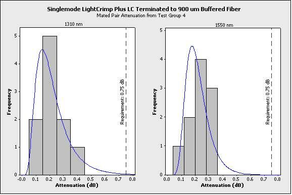
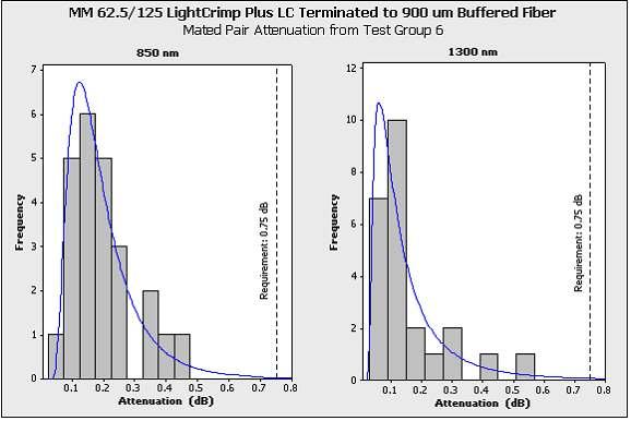
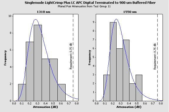
4 2. SUMMARY OF TESTING 2.1. Visual and Mechanical Inspection - All Groups All specimens submitted for testing were manufactured by Tyco Electronics, and were inspected and accepted by the Product Assurance Department of the Fiber Optics Business Unit. For specimens in Test Groups 1, 2, 3 and 7 (total quantity of 32), 6 dimensions were verified and met criteria per FOCIS 10 Fiber Optic Connector Intermateability Standard - Type LC, TIA B Initial Optical Performance - All Groups All attenuation and return loss measurements met the specification requirements. Attenuation and return loss were measured at 1310 and 1550 nm for singlemode and 850 and 1300 nm for multimode. Histograms for attenuation data are provided in the Appendix. Attenuation (Insertion Loss) and Return Loss - Requirements for New Product (db) Performance Requirements Singlemode 1310 and 1550 nm Multimode 850 and 1300 nm Maximum allowed attenuation for any individual specimen Minimum allowed return loss for any individual specimen Attenuation (Insertion Loss) and Return Loss - Actual for New Product (db) Test Groups Maximum and Median Values for Attenuation Minimum and Median Values for Return Loss Singlemode 1310 nm 1550 nm 1310 nm 1550 nm Groups 1, 2 and 3, Standard PC (900 m tight buffered fiber) Group 4, Standard PC (900 m tight-buffered fiber) Groups 7, 8, 9 and 10, Standard PC (2.0 mm jacketed cable) 0.63 maximum 0.21 median 0.41 maximum 0.20 median 0.49 maximum 0.21 median 0.42 maximum 0.19 median 0.34 maximum 0.22 median 0.51 maximum 0.19 median 46 minimum 55 median 48 minimum 56 median 31 minimum 54 median 45 minimum 57 median 51 minimum 58 median 31 minimum 55 median Group 11, APC Digital 0.61 maximum 0.51 maximum 50 minimum 53 minimum (900 um tight-buffered fiber) 0.32 median 0.30 median 56 median 64 median Multimode 850 nm 1300 nm 850 nm 1300 nm Group 5 (50/125) (900 m tight-buffered fiber) Group 6 (62.5/125) (900 m tight-buffered fiber) 0.43 maximum 0.17 median 0.47 maximum 0.17 median 0.34 maximum 0.13 median 0.52 maximum 0.13 median 24 minimum 40 median 34 minimum 37 median 24 minimum 41 median 34 minimum 38 median Rev F 4 of 15
5 2.3. Attenuation, Attenuation Increase and Return Loss - Groups 1-4 and 7-10 Group 1 2 All attenuation, attenuation increase and return loss measurements met the specification requirements. All measurements were recorded at 1310 and 1550 nm for 9/125 m fiber size. Values shown in the table below represent maximum attenuation, maximum attenuation increase and minimum return loss. Condition Temperature life Requirements (1310 and 1550 nm) Actual (1310 nm) Actual (1550 nm) Before During After Before During After Before During After IL IL IL, RL, IL IL IL IL, RL, IL IL IL IL, RL, IL Low temperature NA 0.37 NA Humidity, steady state Temperature cycling, Part 1 (Note 2) Temperature cycling, Part 2 (Note 2) Cable retention, 0 degree Cable retention, 90 degree Flex NA NA NA 0.36 NA NA NA NA 0.31 NA 0.75 NA 0.5(IL ) Twist 0.68 Strength of coupling 0.61 mechanism Impact Mating durability 0.75 NA 4 Strength of coupling mechanism Cable retention, 0 degree 0.75 NA 0.5(IL ) NA 0.33 NA 5 Attenuation and See paragraph Return loss NA 0.36(IL) 45(RL) 0.35(IL) 47(RL) 0.36(IL) 42(RL) 0.36(IL) 41(RL) 0.29(IL) 41(RL) 0.61(IL) 0.01(IL ) 48(RL) 0.57(IL) 0.00(IL ) 48(RL) 0.68(IL) 34(RL) 0.67(IL) 34(RL) 0.61(IL) 43(RL) 0.60(IL) 48(RL) 0.30(IL) 48(RL) 0.41(IL) 49(RL) 0.59(IL) 0.27(IL ) 53(RL) 0.31 NA NA 0.26 NA NA 0.28 NA Attenuation, Change in Attenuation, Attenuation Increase and Return Loss (continued) NA 0.29(IL) 52(RL) 0.29(IL) 45(RL) 0.29(IL) 44(RL) 0.29(IL) 45(RL) 0.26(IL) 45(RL) 0.43(IL) 0.01(IL ) 50(RL) 0.38(IL) 0.00(IL ) 50(RL) 0.47(IL) 37(RL) 0.46(IL) 37(RL) 0.43(IL) 46(RL) 0.44(IL) 50(RL) 0.30(IL) 45(RL) 0.35(IL) 52(RL) 0.51(IL) 0.22(IL ) 53(RL) Rev F 5 of 15
6 Group Condition Temperature life Requirements (1310 and 1550 nm) Actual (1310 nm) Actual (1550 nm) Before During After Before During After Before During After IL IL IL, RL, IL IL IL IL, RL, IL IL IL IL, RL, IL Low temperature NA 0.50 NA Humidity, steady state Temperature cycling Part 1 (see Note) Strength of coupling mechanism Cable retention, 0 degree Cable retention, 90 degree Flex NA NA NA 0.52 NA 0.75 NA 0.75 NA 0.5(IL ) 0.32 NA Twist 0.71 Impact Mating durability 0.75 NA NA 0.50 NA Attenuation and 11 See paragraph 2.2. Return Loss 0.53(IL)43( RL) 0.54(IL) 38(RL) 0.53(IL) 38(RL) 0.54(IL) 38(RL) 0.35(IL) 39(RL) 0.46(IL) 0.05(IL ) 42(RL) 0.63(IL) 0.27(IL ) 42(RL) 0.71(IL) 42(RL) 0.67(IL) 42(RL) 0.49(IL) 41(RL) 0.51(IL) 32(RL) 0.37 NA NA 0.36 NA N/A 0.55 NA 0.43(IL) 41(RL) 0.42 (IL) 37 (RL) 0.40(IL) 37(RL) 0.43(IL) 36(RL) 0.35(IL) 33(RL) 0.58(IL) 0.04 (IL ) 35(RL) 0.60(IL) 0.26(IL ) 35(RL) 0.60(IL) 35(RL) 0.58(IL) 35(RL) 0.45(IL) 36(RL) 0.52(IL) 31(RL) NOTE Test is not required by ANSI/TIA-568-C.3 or (IL) - Insertion Loss (Attenuation) (IL ) - Insertion Loss (Attenuation) Increase (RL) - Return Loss 2.4. Temperature Life - Groups 1 and 7 Attenuation, Attenuation Increase and Return Loss (end) There was no evidence of physical damage to the connector or terminated fiber after temperature life. All attenuation and return loss measurements met specified limits before and after test Low Temperature - Groups 1 and 7 There was no evidence of physical damage to the connector or terminated fiber and no increase in attenuation beyond the specified limit during low temperature exposure. All attenuation and return loss measurements met requirements before and after test. Rev F 6 of 15
7 2.6. Humidity, Steady State - Groups 1 and 7 There was no evidence of physical damage to the connector or terminated fiber and no increase in attenuation beyond the specified limits during steady state humidity. All attenuation and return loss measurements met requirements before and after test Temperature Cycling, Part 1 - Groups 1 and 7 There was no evidence of physical damage to the connector or terminated fiber due to temperature cycling exposure. Although this test is not required by ANSI/TIA-568-C.3, all attenuation and return loss measurements recorded before and after temperature cycling still met the optical performance limits stated in ANSI/TIA-568-C Temperature Cycling, Part 2 - Group 1 There was no evidence of physical damage to the connector or terminated fiber due to temperature cycling exposure. Although this test is not required by ANSI/TIA-568-C.3, all attenuation and return loss measurements recorded before and after temperature cycling still met the optical performance limits stated in ANSI/TIA-568-C Cable Retention, 0 Degree - Groups 2, 4 and 9 There was no evidence of fiber pullout, or other damage to the connector or attached fiber and no increase in attenuation beyond the specified limits after cable retention. Attenuation and return loss measurements met the specified limits before and after the 0 degree cable retention test Cable Retention, 90 Degree - Groups 2 and 9 There was no evidence of fiber pullout, or other damage to the connector or attached fiber and no increase in attenuation beyond the specified limits after 90 degree cable retention. Attenuation and return loss measurements met the specified limits before and after the 90 degree cable retention test Flex - Groups 2 and 9 There was no evidence of physical damage to the connector or attached fiber. Attenuation and return loss measurements met the specified limits before and after flex testing Twist - Groups 2 and 9 There was no evidence of physical damage to the connector or attached fiber. Attenuation and return loss measurements met the specified limits before and after the twist test Strength of Coupling Mechanism - Groups 2, 4 and 8 There was no evidence of physical damage to the connector or attached fiber. Attenuation and return loss measurements met the specified limits before and after strength of coupling mechanism test Impact - Groups 2 and 9 There was no evidence of physical damage to the connector due to impact testing. Attenuation and return loss measurements met the specified limits before and after test Durability - Groups 3 and 10 There was no evidence of physical damage to the connector or attached fiber. Attenuation and return loss measurements met the specified limits before and after durability. Rev F 7 of 15
8 3. TEST METHODS The singlemode environmental facility is an automated, TIA B compliant test system. Following the installation of the specimens, the sequential testing was performed. Multimode optical tests and some singlemode mechanical tests were obtained using manually operated TIA B compliant test equipment. Initial specimen installation was performed according to TIA/EIA A procedures. Following the installation of the specimens, the sequential testing was performed Visual and Mechanical Inspection Product drawings and inspection plans were used to examine the specimens. They were examined visually and functionally. Thirty-two specimens were measured to verify conformance to Dimensions B, D, G, H1, H2 and S in the FOCIS 10 Fiber Optic Connector Intermateability Standard - Type LC, TIA B. Other dimensions not measured on actual test specimens are assumed to be compliant with FOCIS 10 dimensions from Tyco Electronics First Article approval, which included verification of product drawings per the dimensions specified in TIA B Attenuation (Insertion Loss) All singlemode attenuation was measured in accordance with TIA/EIA A, Method D3 processes, except that the launch was part of the specimen under test and was not reference quality. The initial optical power through each launch fiber was measured. The LightCrimp Plus LC connector was terminated to the fiber and optical power was measured from the connector end. The LightCrimp Plus connector was then mated to an epoxy-style LC connector and optical power was measured from the receive fiber. Attenuation was calculated by taking the difference between the first and third measurements. The receive fiber was then spliced to a test lead attached to the optical measurement equipment. Optical power readings were compensated by changes in a source monitor cable. In cases where a control cable was also used and exceeded limits stated in the specification, the change in the control cable was also factored into the loss All multimode attenuation was measured in accordance with TIA/EIA A, Method D1 processes, except that the launch was part of the specimen under test and was not reference quality. The initial optical power through each launch fiber was measured. The LightCrimp Plus LC connector was terminated to the fiber and optical power was measured from the connector end. The LightCrimp Plus connector was then mated to an epoxy-style LC connector and optical power was measured from the receive fiber. Attenuation was calculated by taking the difference between the first and third measurements. Optical power readings were compensated by changes in a source monitor cable Return Loss Return loss was measured in accordance with TIA/EIA A or TIA/EIA A single measurement was recorded for return loss. Return loss was measured initially and after each test evaluation Attenuation Increase Increase in attenuation was calculated by taking the difference between the initial measurement before test and the during/after measurements for each test as applicable. Attenuation increase represents the maximum change in attenuation that results from a decrease in optical power (degraded performance). Rev F 8 of 15
9 3.5. Temperature Life Mated specimens were subjected to 60 C for a period of 96 hours (4 days). Optical performance for each sample was recorded before and after exposure with the specimens in place in the test chamber. Final optical performance was recorded 2 hours after the chamber's return to ambient conditions Low Temperature Mated specimens were subjected to -10 C for a period of 96 hours (4 days). Optical performance for each sample was recorded before and after exposure with the samples in place in the test chamber and at 10 minute intervals throughout the exposure. Final optical performance was recorded 2 hours after the chamber's return to ambient conditions Humidity, Steady State Mated specimens were preconditioned at 50 ± 5 C and low humidity for 24 hours then brought to ambient for at least 1 hour before starting humidity exposure of 40 ± 2 C at 90 to 95% RH for a period of 96 hours (4 days). Optical performance for each specimen was recorded before and after humidity exposure with the specimens in place in the test chamber and at 10 minute intervals throughout the exposure. Final optical performance was recorded 2 hours after the chamber's return to ambient conditions Temperature Cycling, Part 1 Mated specimens were subjected to 5 cycles between -10 and 60 C with 1 hour dwells at each temperature extreme. Ramp rate was 1 C per minute. Each cycle started with a cold ramp/dwell of -10 C then followed by a hot ramp/dwell to 60 C. Optical performance was recorded at ambient before and after exposure with the specimens in place in the test chamber and at 10 minute intervals throughout the exposure Temperature Cycling, Part 2 Mated specimens were subjected to 5 cycles between -40 and 70 C with 1 hour dwells at each temperature extreme. Ramp rate was 1 C per minute. Each cycle started with a cold ramp/dwell of -40 C then followed by a hot ramp/dwell to 70 C. Optical performance was recorded at ambient before and after exposure with the specimens in place in the test chamber and at 10 minute intervals throughout the exposure. Temperature exposure is more harsh than the range specified in ANSI/TIA-568-C Cable Retention, 0 Degree A. Group 2 Specimens terminated to 900 m buffered fiber were subjected to a sustained load of 2.2 N [0.5 lbf] for a minimum of 5 seconds (load meets TIA/EIA-568-B.3; see Group 4 for ANSI/TIA-568-C.3 performance). An adapter was secured to the test fixture. The tensile load was manually applied by wrapping the buffered fiber around a mandrel at a point approximately 23 cm [9 in] from the connector boot of a mated specimen. Optical performance was measured before and after test with the load removed. B. Group 4 Specimens were tested similarly to Group 2 except the load was 5 N [1.1 lbf] (meets ANSI/TIA-568-C.3 requirement). Load was applied at a rate of 0.5 N per second and held for a minimum of 5 seconds. Rev F 9 of 15
10 C. Group 9 For connectors terminated to jacketed cable with strength members, a load of 50 N [11.24 lbf] was applied to a duplex specimen for a minimum of 5 seconds (meets ANSI/TIA-568-C.3 requirement). A duplex adapter was secured to the test fixture. The tensile load was manually applied by wrapping the jacketed cable around a 7.6 cm [3 in] mandrel at a point approximately 23 cm [9 in] from the connector. Optical performance was measured before and after test with the load removed Cable Retention, 90 Degree Flex Twist Specimens terminated to 900 m buffered fiber were subjected to a sustained load of 2.2 N [0.5 lbf] for a minimum of 5 seconds (load is slightly greater than ANSI/TIA-568-C.3 requirement). An adapter was secured to the test fixture. The load was manually applied at a 90 degree pull angle by wrapping the buffered fiber around a mandrel at a point approximately 23 cm [9 in] from the connector boot of a mated specimen. Optical performance was measured before and after test with the load removed. For connectors terminated to jacketed cable with strength members terminated to the connector, a load of 19.4 N [4.4 lbf] was applied to a duplex specimen for a minimum of 5 seconds. A duplex adapter was secured to the test fixture. The load was manually applied at a 90 degree pull angle by wrapping the jacketed cable around a 7.6 cm [3 in] mandrel at a point approximately 23 cm [9 in] from the connector. Optical performance was measured before and after test with the load removed. Specimens were subjected to 100 cycles of fiber flexing. The flex arc was ± 90 degree from a vertical position. Specimens were tested at a rate of approximately 15 cycles per minute. A mandrel was used to apply a tensile load to the buffered fiber or cable at a point approximately 23 cm [9 in] from the boot of a mated connector. Optical performance was measured before and after test with the load removed. For 900 m buffered fiber, the load used was 2.2 N [0.5 lbf] (slightly greater load than required by ANSI/TIA-568-C.3). For jacketed cable (with strength members terminated to the connector), a load of 4.9 N [1.1 lbf] (meets ANSI/TIA-568-C.3 requirement) was applied to a mated, duplex specimen. Specimens were manually subjected to 10 cycles of twist. A mandrel was used to apply a tensile load to the buffered fiber or cable at a point approximately 23 cm [9 in] from the ferrule endface of a mated specimen. The twist motion for each cycle was ± 2.5 revolutions about the axis of the fiber. Optical performance was measured before and after test with the load removed. For 900 m buffered fiber, the load used was 2.2 N [0.5 lbf] (slightly greater load than required by ANSI/TIA-568-C.3). For jacketed cable (with strength members terminated to the connector), a load of 15 N [3.4 lbf] (meets ANSI/TIA-568-C.3 requirement) was applied to a mated, duplex specimen Strength of Coupling Mechanism A. Groups 2 and 8 A 33 N [7.4 lbf] tensile load (meets TIA/EIA-568-B.3; see Group 4 for ANSI/TIA-568-C.3 performance) was applied between the connector plug and adapter at a rate of 25.4 mm [1 in] per minute. The load was sustained for a minimum of 5 seconds. Optical performance was measured before and after test with the load removed. Rev F 10 of 15
11 B. Group Impact Specimens were tested similarly to Groups 2 and 8 except the load was 40 N [9.0 lbf] and was applied at a rate of 2 N [0.45 lbf] per second (meets ANSI/TIA-568-C.3 requirements). An unmated connector was dropped from a height of 1.8 m [70.9 in] onto a concrete slab (exception to ANSI/TIA-568-C.3) while the fixed end was mounted at a height of 0.60 m [2 ft] with cable length of 2 m [79 in]. A ferrule cap was used to protect the fiber endface. The impact exposure was performed 8 times. Initial optical performance was recorded before the specimen was unmated and exposed to testing. After completion of the 8 impacts, each connector was inspected, cleaned and re-mated before recording final optical measurements. Test drop height and duration were harsher criteria than ANSI/TIA-568-C.3 requirements Durability The launch connector of each mated specimen was subjected to 500 cycles of durability. Specimens were manually cycled at a rate not in excess of 300 cycles per hour. The connector and adapter were cleaned as necessary per manufacturer's instructions. Attenuation and return loss were measured before and after test. Specimens were unmated, cleaned, inspected, and re-mated before final optical measurements. Rev F 11 of 15
12 APPENDIX Histograms of Mated Pair Attenuation for LightCrimp Plus LC Connector Rev F 12 of 15

13 Rev F 13 of 15

14 Rev F 14 of 15

15 Rev F 15 of 15
Apr06 Rev A
 Qualification Test Report LC, Multimode, One-Piece Housing, Fiber Optic Connector 501-628 03Apr06 Rev A 1. INTRODUCTION 1.1. Purpose 1.2. Scope Testing was performed on Tyco Electronics LC multimode, one-piece
Jan07 Rev B
 Qualification Test Report 501-545 05Jan07 Rev B MT-RJ Patch Panel and Outlet Jacks (Standard, XG, SECURE and SECURE XG) 1. INTRODUCTION 1.1. Purpose Testing was performed on Tyco Electronics MT-RJ Jack,
Qualification Test Report LC Duplex Adapter For LC Cutouts
 Qualification Test Report LC Duplex Adapter For LC Cutouts 501-683 09Mar09 Rev B 1. INTRODUCTION 1.1. Purpose Testing was performed on Tyco Electronics LC Duplex Adapters for LC Cutouts, to determine their
Jul07 Rev C
 Product Specification 108-2167 11Jul07 Rev C MPO and MPO SECURE Multimode Fiber Optic Connector and Adapter 1. SCOPE 1.1. Content This specification, which is based on GR-1435-CORE, covers the performance,
Product Specification EMI Shielded Duplex LC Sealed Receptacle (ODVA Conforming)
") Product Specification EMI Shielded Duplex LC Sealed Receptacle (ODVA Conforming) 02Oct08 Rev A 1. SCOPE 1.1. Content This specification, based on IEC 61753-1 Edition 1.0 tests for Category E (Extreme Environment),
Product Specification EMI Shielded Duplex LC Sealed Receptacle (ODVA Conforming) 02Oct08 Rev A 1. SCOPE 1.1. Content This specification, based on IEC 61753-1 Edition 1.0 tests for Category E (Extreme Environment),
MT-RJ Optical Fiber System Field Testing
 MT-RJ Optical Fiber System Field Testing Table of Contents INTRODUCTION... 3 TEST JUMPERS... 4 LAUNCH CONDITIONS... 4 MT-RJ TEST KITS... 5 MT-RJ SYSTEM TESTING: Fixed transmit and receive (SC or ST-style)
/Mar/2014 Rev A
 Qualification Test Report 501-93038 21/Mar/2014 Rev A MPOptimate FO Microcassette 12 fiber MPO-12xLC/PC 1. INTRODUCTION 1.1 Purpose Tests performed on MPOptimate FO Microcassette 12 fiber MPO-12xLC/PC,
Jun08 Rev A
 Product Specification Terminal Block Crimp Snap Plug Assembly 108-2319 09Jun08 Rev A 1. SCOPE 1.1. Content This specification covers performance, tests and quality requirements for the Tyco Electronics
Mar11 Rev B
 Product Specification 108-1576-2 11Mar11 Rev B NETCONNECT*, CHAMP* System 5 Modular Jack Patch Panel 1. SCOPE 1.1. Content This specification covers performance, tests and quality requirements for NETCONNECT*
Jun08 Rev C
 Product Specification Connector, Card Edge,.050 Centerline 108-14034 02Jun08 Rev C 1. SCOPE 1.1. Content This specification covers performance, tests and quality requirements for Tyco Electronics.050 centerline
Two Circuit Heavy Duty Burner Connector
 Product 108-1056 11 Oct.16 Rev B Specification EC 0990-0059-05 Two Circuit Heavy Duty Burner Connector 1. SCOPE 1.1. Content This specification covers performance, tests and quality requirements for the
Jan05 Rev A EC
 Product Specification Two Circuit Heavy Duty Burner Connector 108-1056 12Jan05 Rev A EC 0990-0059-05 1. SCOPE 1.1. Content This specification covers performance, tests and quality requirements for the
Fiber Optic Products Catalog
 Fiber Optic Products Catalog No epoxy, no polish, no crimp Two fibers in one ferrule MT-RJ Patch Panel Jack packages include: 6 MT-RJ Jacks 2 Actuator Tools 1 Fiber Guide 1 Icon Wheel Bend Limiting Boots
Mar11 Rev C
 Product Specification 108-1441 11Mar11 Rev C Connector, Z-PACK*, 2 mm FB, Signal and Power 1. SCOPE 1.1. Content This specification covers performance, tests and quality requirements for the Z-PACK* 2mm
Qualification Test Report. AMP-TWIST Series Jacks for Class EA systems
 Qualification Test Report 501-93032 14/April/2011 Rev A AMP-TWIST Series Jacks for Class EA systems 1. INTRODUCTION 1.1 Purpose Qualification testing on AMP-TWIST* Series Jacks for Class E A Systems, to
/Oct/2014 Rev B
 Product Specification 108-93042 07/Oct/2014 Rev B Class EA shielded solid Patch cords 1. SCOPE 1.1 Content This specification describes performance and material requirements and tests procedures for TE
GR-326-CORE Singlemode Optical Connectors and Jumper Assemblies
 Preface...Preface 1 1. Introduction... 1 1 1.1 Purpose and Scope... 1 1 1.2 Target Audience... 1 2 1.3 Structure and Use of This Document...1 2 1.4 Changes from Issue 2 of GR-326-CORE... 1 3 1.5 Requirements
TE CONNECTIVITY <fiber count> <fiber type> <flame rating> MM/YY SO<shop order number> XXXXX FEET
 Optic Backbone Distribution Cables 900um Buffered Aramid Yarn Strength Members Outer 6 or 12 Subunit Central Strength Member Outer Ripcord Single Unit Cable 6-24 Multi-Unit Cable 24-144 Description: TE
Special Provision No. 683S28 December 2017
 FIBRE OPTIC COMMUNICATION CABLES, AERIAL ON MESSENGER CABLE - Item No. FIBRE OPTIC COMMUNICATION CABLES, AERIAL ON MESSENGER CABLE (TEMPORARY) - Item No. Special Provision No. 683S28 December 2017 1. SCOPE
Fibre Optic Connector and Component Standards Developments & Key Issues in IEC & CENELEC. Philip C Longhurst Corporate Fibre Optic R & D Manager
 Fibre Optic Connector and Component Standards Developments & Key Issues in IEC & CENELEC Philip C Longhurst Corporate Fibre Optic R & D Manager Outline CENELEC TC86BXA work programme IEC SC86B WG 6 and
ITU-T L.404. Field mountable single-mode optical fibre connectors
 I n t e r n a t i o n a l T e l e c o m m u n i c a t i o n U n i o n ITU-T L.404 TELECOMMUNICATION STANDARDIZATION SECTOR OF ITU (08/2017) SERIES L: ENVIRONMENT AND ICTS, CLIMATE CHANGE, E-WASTE, ENERGY
FiberExpress Solutions
 7.2.1-A 7.2.1-B 7.2.1-C 7.2.1-D Simplex Patch Cord Duplex Patch Cord Hybrid Patch Cord Single-ended (pigtails) AX200057 Patch Cord Multimode SC Duplex DESCRIPTION FiberExpress Simplex and Duplex Patch
Connections You Can Count On.
 Connections You Can Count On. XPRESS ULTRA FIBER CONNECTOR PRODUCT GUIDE - CLEANING & INSPECTION - TESTING AND TROUBLE SHOOTING - XPRESS ULTRA FIBER CONNECTORS - INSTALLATION KITS Connections You Can Count
Fiber Optic Distribution Cables (6-144 Fibers)
") 900um Buffered Aramid Yarn Strength Members Outer 6 or 12 Subunit Central Strength Member Outer Ripcord Single Unit Cable 6-24 Multi-Unit Cable 24-144 Description: AMP NETCONNECT distribution cables are
900um Buffered Aramid Yarn Strength Members Outer 6 or 12 Subunit Central Strength Member Outer Ripcord Single Unit Cable 6-24 Multi-Unit Cable 24-144 Description: AMP NETCONNECT distribution cables are
2016 CDM Smith All Rights Reserved July 2016 SECTION FIBER OPTIC DATA NETWORK
 PART 1 GENERAL 1.01 SCOPE OF WORK SECTION 27 12 23 FIBER OPTIC DATA NETWORK A. Furnish, install, terminate, and test all fiber optic equipment and cabling necessary for a complete and functional data highway
SECTION COMMUNICATIONS OPTICAL FIBER BACKBONE CABLING
 SECTION 27 13 23 COMMUNICATIONS OPTICAL FIBER PART 1 - GENERAL 1.1 SUMMARY A. Section Includes the following: 1. 50/125-micrometer, optical fiber cabling. 2. Cable connecting hardware, termination panels,
JUL 18 Rev A1
 Qualification Test Report 501-166004 30 JUL 18 Rev A1 Mini USB-B Header, H-Type SMT 1. INTRODUCTION 1.1. Purpose Testing was performed on the Mini USB-B Header, H-Type SMT to determine if it meets the
Applications Engineering Notes
 Applications Engineering Notes Document Title Document Number Revision Number Product Specification and Qualification Test Report: IBC Brand Fiber Optic Connector Cleaner MT38 II AEN-1146 Issue Effective
/Oct/2014 Rev E
 Product Specification 108-93017 14/Oct/2014 Rev E Cat 6 Unshielded Patch Cords 1. SCOPE 1.1 Content This specification describes performance and material requirements and tests procedures for TE Connectivity
Cat 6 Shielded Patch cords
 Product Specification 108-93010 14/Oct/2009 Rev E Cat 6 Shielded Patch cords 1. SCOPE 1.1 Content This specification describes performance and material requirements and tests procedures for AMP NETCONNECT*
Industrial Fiber Optic Cables, LSZH Corrugated Armored Cable, Fibers
 Features and Benefits Corrugated armor Mechanical protection Low-smoke/zero-halogen (LSZH ) sheath Key life-safety benefit Meets cyclic impact and chemical resistance test Superior performance Tray-rated
Product Specification Qualification Test Report
 PS 88 / DMI PC SM / 6/5 DIAMOND Test & Calibration Laboratory STS 333 / SCS 11 Product Specification Qualification Test Report DMI PC SM DIAMOND SA Via dei Patrizi 5 CH-6616 LOSONE Tel. +41 91 785 45 45
Fibre (TIA) Field Test Specification
 Field Test Specification") This document has been prepared to aid consultants or engineers in developing contractual specifications covering the testing of duplex fibre optic cabling installations. It is offered as a general guide.
This document has been prepared to aid consultants or engineers in developing contractual specifications covering the testing of duplex fibre optic cabling installations. It is offered as a general guide.
Draft ES V1.1.1 ( )
") Standard Transmission and Multiplexing (TM); Passive optical components; Fibre optic mechanical splices for single-mode optical fibre communications systems; Common requirements and conformance testing
Standard Transmission and Multiplexing (TM); Passive optical components; Fibre optic mechanical splices for single-mode optical fibre communications systems; Common requirements and conformance testing
Cat 6 Unshielded Patch cords
 Product Specification 108-93017 13/Oct/2009 Rev D Cat 6 Unshielded s 1. SCOPE 1.1 Content This specification describes performance and material requirements and tests procedures for AMP NETCONNECT* Cat
FIBRE OPTIC COMMUNICATION CABLES, IN DUCTS - Item No. FIBRE OPTIC COMMUNICATION CABLES, IN DUCTS (TEMPORARY) - Item No.
 - Item No.") FIBRE OPTIC COMMUNICATION CABLES, IN DUCTS - Item No. FIBRE OPTIC COMMUNICATION CABLES, IN DUCTS (TEMPORARY) - Item No. Special Provision No. 683S01 December 2017 1. SCOPE This Special Provision covers
FIBRE OPTIC COMMUNICATION CABLES, IN DUCTS - Item No. FIBRE OPTIC COMMUNICATION CABLES, IN DUCTS (TEMPORARY) - Item No. Special Provision No. 683S01 December 2017 1. SCOPE This Special Provision covers
APR 17 Rev A
 Product Specification 108-130015 11 APR 17 Rev A ChipConnect Cable Assembly 1. SCOPE 1.1. Content This specification covers performance, test and quality requirements for the ChipConnect Cable Assembly
FEB. 17 Rev. A1
 Product Specification 108-94552 10 FEB. 17 Rev. A1 The product described in this document has not been fully tested to ensure conformance to the requirements outlined below. Therefore, TE Connectivity
MODULAR CONNECTOR 154 (58 AND 96) POS, WATERPROOF PRODUCT SPECIFICATION
 POS, WATERPROOF PRODUCT SPECIFICATION") MODULAR 154 (58 AND 96) POS, WATERPROOF PRODUCT SPECIFICATION 108-18965 Product Specification 108-18965 10.02. 2011 Rev C1 MODULAR 154 (58 AND 96) POSITION, WATERPROOF CONTENT : 1 PRODUCT OVERVIEW 1.1
MODULAR 154 (58 AND 96) POS, WATERPROOF PRODUCT SPECIFICATION 108-18965 Product Specification 108-18965 10.02. 2011 Rev C1 MODULAR 154 (58 AND 96) POSITION, WATERPROOF CONTENT : 1 PRODUCT OVERVIEW 1.1
HOUSING ASSY 5 POS. HYBRID STD/JR POWER TIMER TAB & REC.
 108-37065 Product Specification Rev. A 18-Jan-2007 Housing Assy 5p Hybrid Std./Jr. Power Timer Tab & Rec. DESIGN OBJECTIVES The product described in this document has not been fully tested to insure conformance
Fibrlok II 2529 Universal Optical Fiber Splice
 Fibrlok II 2529 Universal Optical Fiber Splice Technical Report December 1994 Issue 1, 78-8098-3415-9 1 1.0 Product Description The 3M brand Fibrlok II 2529 Universal Optical Fiber Splice is a high performance,
VTI Services Technical Bulletin (TB) OTDR Measurement of Installed Optical Fibre Cabling Permanent Links and Links
 OTDR Measurement of Installed Optical Fibre Cabling Permanent Links and Links") VTI Services Technical Bulletin (TB) OTDR Measurement of Installed Optical Fibre Cabling Permanent Links and Links TB Number 004 This bulletin is supplied for information only and is intended to provide
VTI Services Technical Bulletin (TB) OTDR Measurement of Installed Optical Fibre Cabling Permanent Links and Links TB Number 004 This bulletin is supplied for information only and is intended to provide
INTERNATIONAL TELECOMMUNICATION UNION SERIES L: CONSTRUCTION, INSTALLATION AND PROTECTION OF CABLES AND OTHER ELEMENTS OF OUTSIDE PLANT
 INTERNATIONAL TELECOMMUNICATION UNION ITU-T L.36 TELECOMMUNICATION STANDARDIZATION SECTOR OF ITU (10/98) SERIES L: CONSTRUCTION, INSTALLATION AND PROTECTION OF CABLES AND OTHER ELEMENTS OF OUTSIDE PLANT
The True Value of Connector Inspection: New Challenges and Best Practices
 The True Value of Connector Inspection: New Challenges and Best Practices Vincent Racine Product Line Manager August 2011 1 Table of contents 1 Best Practices 2 Connector Inspection Tools 3 Connector Inspection
A. General: Horizontal and backbone cabling shall be verified in accordance with ANSI/TIA/EIA-568-C and the addendum for fiber optic testing.
 3.4 TESTING OF FIBER OPTICS CABLING A. General: Horizontal and backbone cabling shall be verified in accordance with ANSI/TIA/EIA-568-C and the addendum for fiber optic testing. B. General: In the event
Plug shell and receptacle, single cavity, floating, EN Application of modular rectangular modules and shells per EN4165
 PRODUCT SPECIFICATION Sep 22, 29 Rev. B CONNECTOR, SINGLE CAVITY, AEROSPACE, PANEL MOUNT, FLOATING, EN416 1 - SCOPE 1.1. Content This document covers the performances, tests, and quality requirements of
Fiber Optic Patch Cord and Pigtails
 Fiber Optic Patch Cord and Pigtails Description The optical fiber patch cords are fitted at both ends with same connector types or different connector types. Our fiber optic patch cords are ultra reliable
USB 3.0 Plug & Receptacle
 US 3.0 Plug & Receptacle 1. Scope: 1.1 Contents: This specification covers the requirements for product performance, test methods and quality requirements of Tyco Electronics Universal Serial us (US) consortium
Product Specification CAT 6 UNSHIELDED PATCH CORDS
 Product 108-93017 Specification 23/Nov/06 Rev. A CAT 6 UNSHIELDED PATCH CORDS 1. SCOPE 1.1 Content This specification describes performance and material requirements and tests procedures for NETCONNECT
FTTX Solutions Mini Rapid Fiber Distribution Terminal (RDT)
") TE Connectivity's (TE) FTTX infrastructure solutions are designed from the ground up to meet the unique requirements of FTTX networks. Designed for operational efficiency and scalability, TE s FTTX solutions
TE Connectivity's (TE) FTTX infrastructure solutions are designed from the ground up to meet the unique requirements of FTTX networks. Designed for operational efficiency and scalability, TE s FTTX solutions
ETSI TS V1.2.1 ( )
") TS 100 783 V1.2.1 (2004-08) Technical Specification Transmission and Multiplexing (TM); Passive optical components; Fibre optic fusion splices for single-mode optical fibre transmission systems for indoor
TS 100 783 V1.2.1 (2004-08) Technical Specification Transmission and Multiplexing (TM); Passive optical components; Fibre optic fusion splices for single-mode optical fibre transmission systems for indoor
This is a preview - click here to buy the full publication
 ISO/IEC 14763-3 CONSOLIDATED VERSION Edition 2.1 2018-08 colour inside Information technology Implementation and operation of customer premises cabling Part 3: Testing of optical fibre cabling INTERNATIONAL
ETSI TS V1.2.1 ( )
") TS 101 263 V1.2.1 (2004-07) Technical Specification Transmission and Multiplexing (TM); Passive optical components; Fibre optic mechanical splices for single-mode optical fibre communications systems for
TS 101 263 V1.2.1 (2004-07) Technical Specification Transmission and Multiplexing (TM); Passive optical components; Fibre optic mechanical splices for single-mode optical fibre communications systems for
LSH (E 2000 ) High performance. High reliability. High safety. High flexibility
 High performance. High reliability. High safety. High flexibility") E-2000 is a high performance connector which meets the highest standards y excellence in design and manufacturing processes. Only high quality and high precision materials are used to guarantee connections
E-2000 is a high performance connector which meets the highest standards y excellence in design and manufacturing processes. Only high quality and high precision materials are used to guarantee connections
Field Testing and Troubleshooting of PON LAN Networks per IEC Jim Davis Regional Marketing Engineer Fluke Networks
 Field Testing and Troubleshooting of PON LAN Networks per IEC 61280-4 Jim Davis Regional Marketing Engineer Fluke Networks Agenda Inspection and Cleaning APC vs UPC PON basics Wavelengths Architecture
Best Practice Briefing
 Best Practice Briefing Fiber Optic Connector Handling, Inspection, andcleaning microwave photonic systems Expand Your RF Horizons Briefing Overview Personnel Safety & Best Practices Insertion Loss (IL)
Hands-On Fiber Optics ISP/OSP - Advanced Combo- Tech
 Hands-On Fiber Optics ISP/OSP - Advanced Combo- Tech Course Description This Hands-On 3-day course has been customized to provide technicians with a practical understanding of fiber optic theory and fiber
4120 Fire Alarm Network Reference
 4120 Fire Alarm Network Reference Features Autocall 4120 Fire Alarm Network communications are available for wired or fiber optic connections Wired communications are available on Network Interface Cards
SECTION COMMUNICATIONS FIBER CABINETS, ADAPTERS AND CONNECTORS
 SECTION 27 11 20 COMMUNICATIONS FIBER CABINETS, ADAPTERS AND CONNECTORS PART 1 GENERAL 1.01 DESCRIPTION A. The work covered by this section of the Specifications includes all labor necessary to perform
Qualification Testing of Nuclear High Voltage Splice (NHVS) Title Pages: 49. Report Number: EDR-5391 Rev. 0 06/15/05. Approved by: Signature: Date:
 Title Pages: 49. Report Number: EDR-5391 Rev. 0 06/15/05. Approved by: Signature: Date:") Energy Report EDR-5391 Qualification Testing of Nuclear High Voltage Splice (NHVS) Title Pages: 49 Qualification Testing of Nuclear High Voltage Splice (NHVS) Enclosures: Report Number: Date: EDR-5391
Energy Report EDR-5391 Qualification Testing of Nuclear High Voltage Splice (NHVS) Title Pages: 49 Qualification Testing of Nuclear High Voltage Splice (NHVS) Enclosures: Report Number: Date: EDR-5391
Ensuring Cabling Performance in the Customer-Owned Outside Plant. Keith Foord Product Manager Greenlee Communications
 Ensuring Cabling Performance in the Customer-Owned Outside Plant Keith Foord Product Manager Greenlee Communications Introduction: Outside plant fiber networks require low reflectance terminations for
Test Report for Senko Advanced Components, Report No RES3005 February 22, Test Report. Senko Advanced Components
 Test Report Report No. Client: Address: RES3005 Senko Advanced Components 225 Cedar Hill Street Marlboro, MA 01752 Phone: 508-481-9999 Product Tested: Q-XP MSOC 900m Test Dates: April 2010 October 2010
PRODUCT SPECIFICATION. 0.5mm Fine Stacking. Hermaphroditic Type BTB Connector
 PRODUCT SPECIFICATION 108-115057 29OCT13 Rev. A1 0.5mm Fine Stacking Hermaphroditic Type BTB Connector 1. SCOPE 1.1. Content This specification covers performance, tests and quality requirements for 0.5mm
NG4access ODF Platform Standard Chassis Installation Manual
 NG4access ODF Platform Standard Chassis Installation Manual TECP-90-703 Issue 1 8/2012 24939-A Content Page INTRODUCTION...1 1 PRODUCT DESCRIPTION...2 2 MAIN COMPONENTS...3 3 GROUNDING AND BONDING THE
--> Buy True-PDF --> Auto-delivered in 0~10 minutes. YD/T Translated English of Chinese Standard: YD/T
 Translated English of Chinese Standard: YD/T1447-2013 www.chinesestandard.net Sales@ChineseStandard.net COMMUNICATION INDUSTRY STANDARD OF THE PEOPLE S REPUBLIC OF CHINA YD ICS 33.180.10 M 33 Replacing
Free Height 0.8 mm Pitch Board-to-Board Connector (SMT)
") Product 108-5390 Specification 31 OCT 17 Rev.F1 Free Height 0.8 mm Pitch Board-to-Board Connector (SMT) 1. SCOPE 1.1. Contents This specification covers the requirements for product performance, test methods
Product 108-5390 Specification 31 OCT 17 Rev.F1 Free Height 0.8 mm Pitch Board-to-Board Connector (SMT) 1. SCOPE 1.1. Contents This specification covers the requirements for product performance, test methods
Certified Fibre Optic Specialist - Testing
 Certified Fibre Optic Specialist - Testing COURSE DESCRIPTION: This training program is designed to introduce the student to the process of fibre optic network testing. It is intended for those looking
Link loss measurement uncertainties: OTDR vs. light source power meter By EXFO s Systems Engineering and Research Team
 Link loss measurement uncertainties: OTDR vs. light source power meter By EXFO s Systems Engineering and Research Team INTRODUCTION The OTDR is a very efficient tool for characterizing the elements on
Ensuring Cabling Performance in the Customer-Owned Outside Plant
 Ensuring Cabling Performance in the Customer-Owned Outside Plant Needs to be able to qualify the installation to validate bandwidth requirements are met Future high bandwidth applications Future Proof
Sumitomo Fiber Specification SE-9** Non-Zero Dispersion Shifted (NZDF) Zero Water Peak Large Effective Area Single Mode Fiber
 Zero Water Peak Large Effective Area Single Mode Fiber") Sumitomo Fiber Specification SE-9** Non-Zero Dispersion Shifted (NZDF) Zero Water Peak Large Effective Area Single Mode Fiber PureGuide -LA SM Optical Fiber, TIA Type IVd ITU G.655 C and D Compliant Issued:
Sumitomo Fiber Specification SE-9** Non-Zero Dispersion Shifted (NZDF) Zero Water Peak Large Effective Area Single Mode Fiber PureGuide -LA SM Optical Fiber, TIA Type IVd ITU G.655 C and D Compliant Issued:
Copper LAN cable. This specification describes the general requirements for AMP NETCONNECT* copper LAN cable.
 Product Specification 108-93018 25/Aug/2011 Rev H Copper LAN cable 1. SCOPE 1.1. Content This specification describes the general requirements for AMP NETCONNECT* copper LAN cable. 2. APPLICABLE DOCUMENTS
FTTH NETWORK TESTING: REAL APPLICATIONS USING THE OLTS METHOD
 FTTH NETWORK TESTING: REAL APPLICATIONS USING THE OLTS METHOD 157 APPLICATION NOTE Mario Simard, Product Manager, Optical Business Unit The purpose of any fiber-optic network is to perform high-speed,
Side Entry Insulation Damage Repair Sleeve (SEIDRS) Raychem Devices Products
 Raychem Devices Products") 1.0 Scope This specification covers the design, performance and qualification requirements for Raychem Side Entry Insulation Damage Repair Sleeve. 1.1 Description. Raychem SEIDRS covered by this specification
1.0 Scope This specification covers the design, performance and qualification requirements for Raychem Side Entry Insulation Damage Repair Sleeve. 1.1 Description. Raychem SEIDRS covered by this specification
Fiber Optic Connector Cleaning and Inspection Kit Instructions
 Instruction Sheet 860376037 Rev E, March 2018 Fiber Optic Connector Cleaning and Inspection Kit Instructions General This instruction sheet describes the use of the CommScope Fiber Optic Connector Cleaning
STANDARD FOR INDOOR-OUTDOOR OPTICAL FIBER CABLE
 STANDARD FOR INDOOR-OUTDOOR OPTICAL FIBER CABLE Publication # ICEA S-104-696 Second Edition March 2013 2013 by ICEA INSULATED CABLE ENGINEERS ASSOCIATION, Inc. STANDARD FOR INDOOR-OUTDOOR OPTICAL FIBER
Hands-On Fiber Optic ISP / OSP Combo-Tech Splicing, Termination & Testing
 Hands-On Splicing, Termination & Testing BICSI CECs This course has been approved for CEC credits by BICSI. Please read below for a breakdown of the credits that we offer for this course. For more information
ECP OPTICAL FIBRE SPLICING, TESTING AND COMMISSIONING REQUIREMENTS
 Network(s): Summary: ENGINEERING COMMISSIONING PROCEDURE ECP 11-0009 OPTICAL FIBRE SPLICING, TESTING AND COMMISSIONING REQUIREMENTS EPN, LPN, SPN This standard details the requirements for the splicing,
OWL. Laser OWL Series. Operations Guide. Singlemode Light Sources. Optical Wavelength Laboratories. Date: October 1, 2015
 Laser OWL Series Operations Guide Singlemode Light Sources OWL Optical Wavelength Laboratories Operations Guide Laser OWL and Laser OWL HP Singlemode Light Sources Date: October 1, 015 Version.5 Optical
MADE FOR THE TRADE! FIBER OPTIC. professional. XL fibertools Series. instruments
 MADE FOR THE TRADE! professional FIBER OPTIC XL fibertools Series instruments XL fibertools Series Instruments Designed for Fiber Optic Cable Testing. The XL fibertools are designed for the professional
SECTION COMMUNICATIONS PATCH CORDS, STATION CORDS AND CROSS CONNECT WIRE
 SECTION 27 16 19 COMMUNICATIONS PATCH CORDS, STATION CORDS AND CROSS CONNECT WIRE PART 1 GENERAL 1.01 DESCRIPTION A. The work covered by this section of the Specifications includes all labor necessary
Noyes OFL 250B Specs Provided by
 Noyes OFL 250B Specs Provided by www.aaatesters.com OFL 250 Handheld OTDR The Noyes OFL 250 from AFL Telecommunications is a single-mode OTDR with an integrated Optical Power Meter (OPM), Source (OLS),
17" UNIVERSAL MOUNT INDUSTRIAL MONITOR REVISION E, F & G PRODUCT RELIABILITY TEST REPORT
 17" UNIVERSAL MOUNT INDUSTRIAL MONITOR REVISION E, F & G PRODUCT RELIABILITY TEST REPORT Model No. HIS-UM17- _ E, HIS-UM17- _ F and HIS-UM17- _ G Table of Contents Test Report Overview... 3 Testing Rationale...3
Sumitomo Fiber Specification SE-6** Non-Zero Dispersion Shifted Single-Mode Fiber. PureGuide SM Optical Fiber, TIA Type IVd. Issued: November 2003
 Sumitomo Fiber Specification SE-6** Non-Zero Dispersion Shifted Single-Mode Fiber PureGuide SM Optical Fiber, TIA Type IVd Issued: November 2003 78 Alexander Drive, Research Triangle Park, NC 27709 Phone
ARINC 801 Fiber Optic Interconnects for Aerospace & Defense. A Complete End-to-End Solution Featuring Connectors, Termini & Cable Harnesses
 ARINC 801 Fiber Optic Interconnects for Aerospace & Defense A Complete End-to-End Solution Featuring Connectors, Termini & Cable Harnesses We Connect the Aerospace & Defense Industry with High-Speed Data,
Figure 1 - Parts of a Fiber Optic Connector
 Fiber Optic Connectors Fiber optic connectors have traditionally been the biggest concern in using fiber optic systems. While connectors were once unwieldy and difficult to use, connector manufacturers
Qualification Test Report 1/Jul/2005 Rev. A
 Qualification Test 501-93013 Report 1/Jul/2005 Rev. A AMP CO 10 Gigabit/s Insert PN 1711188-X 1. INTRODUCTION 1.1 Purpose Testing was performed on AMP* CO 10 Gigabit/s Insert, to determine its conformance
Universal Retention Modules 02 MAR 10 Rev A
 NOTE i Application Specification 114-26017 Universal Retention Modules 02 MAR 10 Rev A All numerical values are in metric units [with U.S. customary units in brackets]. Dimensions are in millimeters [and
Fiber Optic Connector Cleaning Solutions
 Fiber Optic Connector Cleaning Solutions www.usconec.com Table of Contents Fiber Optic Cleaning Guide The Importance of Cleaning 3 Good Cleaning Practices 3 Single Fiber Cleaner Instructions 4 Multi-fiber
Product Specification Mono-Shape TM Mark II - 5mm Pitch I.D.C Connectors, For TAB Contacts - RAST5
 1. SCOPE 1.1 Content This specification covers performance, test and quality requirements for the Mono-Shape Mark II - 5 mm Pitch I.D.C. Connectors for Tab contacts. These connectors are designed and developed
FIBER OPTIC CONNECTOR CLEANERS
 FIBER OPTIC CONNECTOR CLEANERS FIBER OPTIC CONNECTOR CLEANERS TABLE OF CONTENTS Introduction Fiber Optic Connector Cleaning Tools Page 2 Single Fiber Cleaning Tools NEOCLEAN E Refillable Cleaners IBC Brand
SECTION TESTING OF FIBER OPTIC CABLES
 SECTION 27 08 23 TESTING OF FIBER OPTIC CABLES PART 1 GENERAL 1.01 DESCRIPTION A. The work covered by this section of the Specifications includes all labor necessary to perform and complete such construction,
MADE FOR THE TRADE! FIBER OPTIC. professional. XL fibertools Series. instruments
 MADE FOR THE TRADE! FIBER OPTIC professional XL fibertools Series instruments XL fibertools Series Instruments Designed for Fiber Optic Cable Testing. The XL fibertools are designed for the professional
Basic Professional Fiber Optic Installation
 Basic Professional Fiber Optic Installation QUICK SUMMARY Length: 32 hours; or 40 hours with Fiber Optic Association CFOT certification Hands-on Activities: 40 activities, 70-75 % Text/Field Reference:
REPORT NUMBER: SAT-001B ORIGINAL ISSUE DATE: February 29, 2016 REVISED DATE:
 Page 1 of 10 TEST REPORT REPORT NUMBER: 102317918SAT-001B ORIGINAL ISSUE DATE: February 29, 2016 REVISED DATE: EVALUATION CENTER Intertek Testing Services NA Inc. 16015 Shady Falls Road Elmendorf, TX 78112
MicrOTDR. Optical Fault Locator. User Manual
 Optical Fault Locator Datacom Textron 11001 31 st Place West Everett, WA 98204 TEL: 425-355-0590 Toll Free: 800-468-5557 FAX: 425-290-1600 Internet: www.datacom.textron.com Warranty The MicrOTDR Optical
STANDARD TEST PROCEDURE PRE-TEST QUALITY OF OPTIC FIBRE CABLE ON DRUMS TYPE OF CABLE :
 PROCEDURE PRE-TEST QUALITY OF OPTIC FIBRE CABLE ON DRUMS STANDARD TEST PROCEDURE PRE-TEST QUALITY OF OPTIC FIBRE CABLE ON DRUMS TYPE OF CABLE : 1) SINGLE MODE 2) MULTI-MODE IN EXCESS OF 100 METRES PRC-00107
Duct Cable GYTS-144B1.3
 Optical Fibre Cable Technical Specification Duct Cable GYTS-144B1.3 Xcom Ltd All rights reserved 1. Scope This Specification covers the design requirements and performance standard for the supply of optical
. SECTION CONTROL-VOLTAGE ELECTRICAL POWER CABLES
 . SECTION 260523 - CONTROL-VOLTAGE ELECTRICAL POWER CABLES PART I - GENERAL 1.1 RELATED DOCUMENTS A. Drawings and general provisions of the Contract, including General and Supplementary Conditions and
INTERNATIONAL STANDARD
 INTERNATIONAL STANDARD IEC 61753-1-3 Edition 1.0 2014-05 Fibre optic interconnecting devices and passive components Performance standard Part 1-3: General and guidance for single-mode fibre optic connector
Hydraulic Crimping Head, PN
 ORIGINAL INSTRUCTIONS Hydraulic Crimping Head, PN 1752868-1 Instruction Sheet 408-8959 19 JUL 17 Rev C 1. INTRODUCTION Figure 1 This instruction sheet covers application, inspection and maintenance procedures