Intelligent Security & Fire Ltd
|
|
|
- Ashlie Spencer
- 5 years ago
- Views:
Transcription


1 R S INTRUDER ALARM CONTROL PANEL U S E R M A N U A L VERSION 1-5
2 INDEX Page INTRODUCTION 1 THE REMOTE KEYPAD Using the Keypad 2 Text Displays & Menu System 3 Main Menu 4 SINGLE AREA SYSTEM Introduction 5 Full Set 6 Part Set 7 ZONE OMIT 8 SPLIT SYSTEM OPERATION Introduction 9 Setting 10 Unsetting 11 CHIME Introduction 12 Setting when no Areas are Set 12 Setting with a Split System 13 Unsetting 13 PROGRAMMING Using the Text Editor 14 Setting up Access Codes 16 Naming Zones and Areas 18 EVENT LOG Reading and Printing the Event Log 19 SYSTEM TEST Setting the Clock 20 Walk Testing Zones 20 Checking Zone Status 21 Testing Audible Warning Devices 21 REMOTE COMMUNICATION Alarm Receiving Centre 23 Remote Reset 23 APPENDIX Organisation Plans 24 Engineer On Site 24 Printer Options 24 Note: Due to a policy of continued development of the RS125 intruder alarm control panel, the information contained in this guide is subject to change without notice.
3 Introduction The RS125 is a versatile, fully programmable Intruder Alarm Control Panel which will have been set up by your Alarm Company to serve your particular requirements. However there must be at least one person on the premises who takes a special interest in the alarm system. This person, whom we call the System Manager should read this guide carefully in order to get the best performance from the system. The System Manager needs to work in conjunction with the other Users, the Alarm Company and also possibly an Alarm Receiving Centre to ensure that security is maintained and that alarm activations are properly managed. The management approach depends on the size of the system, whether it is a residential or commercial application and also whether a Split System is being used. This manual provides separate Setting instructions for a Single Area Residential System and a Split System; with either type of installation you need only read the relevant sections.there is an Organisation Plan for the System Manager in Appendix 1 which covers both types of installation and a Specification inside the Rear Cover.. The system is operated from one or more Remote Keypads, incorporating a backlit Text Window which provides the user with an easily interpreted series of messages while setting and programming the system. Operation is driven through a series of menu displays which allow most routine functions to be achieved without reference to the manuals. The RS125 allows up to 100 different Users to be provided with individual Access Codes each with their own User ID, Rank, Name Text and Area Authorisation Tags. The Rank of each Access Code is used to determine the level of access to the system:- Master: Boss: This is normally assigned to the System Manager and allows access to all the RS125 User Menu Options. Only one Master Code is allowed and this is allocated the User ID zero, zero, (00). The Master Code can be used to re-program all codes and has access to all Areas. You will be told the Master Code when the Alarm Company hands over the system. Boss Codes are set up using the Master code; they allow access to all the RS125 User Menu Options but cannot be used to change either the Master Code or another Boss s code parameters. Boss Codes can be used to set up lower ranking Users. User +: User: Keyholder: Duress: Engineer: User+ Codes may Set and Unset pre-defined Areas and Omit zones in those areas. User Codes may only Set and Unset pre-defined Areas. This code allows a Guarding Company to switch the alarm off and rearm the system only after an alarm activation has occurred; it is valid for all Areas. A special Access Code used to generate a silent call to the Alarm Receiving Centre. A normal Access Code must be used to reset the system. This code is only accessible to the Alarm Company for engineering use. The RS125 does not provide any means of revealing the Access Codes to anybody. 1
4 The Remote Keypad Numeric Keys and Text Window The numeric keys are used for entering your Access Code to turn the system On and Off. If you enter a wrong code, enter the code again. The Text Window can show a wide variety of messages which in most cases are self explanatory. Note: The [0/CHIME] Key has a Dual Function. The Keypad is also used for other operations which are explained later. Function Keys and Status Display The Blue Function keys are used to operate the security system and to answer questions. The Scroll keys are used to move up and down a Menu or list. The No Line light will only be functional if a Communicator is fitted. STATUS LIGHTS LABEL ON OFF FLASH COLOUR POWER Power OK System Set/No Power Mains Fault Green NO LINE N/A Tel. Line OK Tel. Line Fault Amber The Remote Keypad contains a loudspeaker which can produce the following sounds DESCRIPTION OF SOUNDS Keypad press - Quick blip Fire sound - Two tone sound Entry sound - Solid tone pulsed on and off slowly Night setting - Soft clicking Exit sound - Solid tone Chime - Warble Tamper sound - Fast broken tone Fault sound - Fast broken tone Alarm sound - Wailing tone Error tone - Buzz 2
5 The Text Window Introduction The Text Window is capable of displaying a wide variety of messages; many of these occur as part of the normal day to day usage of the system and these are dealt with in the appropriate sections of this guide. However there may be special circumstances which lead to other messages some of which are explained below; if the Text Window displays a message you are unable to understand you should contact your alarm installation company. DISPLAY READS EXPLANATION ACTION REQUIRED The clock display is replaced by the Service message. Enter code to access options. Call Alarm Company to arrange a service visit. Areas shown in upper case are Set. Areas shown in lower case are set to Chime. Enter code change Set state. Enter code change Chime state. An activation has caused the Panel to require a Rest. Areas shown are currently set to Chime. The Panel requires an Engineer Reset. Another Remote Keypad is currently being accessed by another user. Another Remote Keypad is currently being accessed by an Engineer. Call Alarm Company or Alarm Receiving Centre Enter code to change Chime state Call Alarm Company. Wait until other user has finished. Note that the system is not secure until the engineer Signs Off. Sample Alarm display Where X=Block and N=Zone Number. The fitted communicator has detected a Telephone line fault. The 230v Mains is currently not present. The Panel is now running from Battery only. The Panel battery has become partially flat. Possible due to No Mains. Press [YES/OPTION] to each message until all events have been reported. Check Zones. Check Telephone line. If fault persists, call your Alarm Company. Check Mains supply to Panel. Check spur Fuse OK. Restore Mains power immediately; if fault persists, contact your Alarm Company. 3
6 4
7 Single Area System Operation Introduction A Single Area system with Residential setting mode on Part Guard is the preferred system for a typical domestic situation. All Access Codes are valid for all Areas and the keystroke sequences are kept as simple as possible. Full Set is used when the house is unoccupied and Part Set is used when going to bed. False Alarms Before setting your alarm system it is important to know how to avoid false alarms. Most problems arise when setting or unsetting the system. Here is a check list to help you avoid any potential problems:- Make sure that all doors to be set on the system are firmly closed and cannot swing open accidentally. Check that areas covered by movement detectors (e.g. Passive Infra-Red detectors [P.I.R s]) are free from moving objects such as pets and moving curtains. When re-entering the protected area proceed directly to the nearest Remote Keypad without delay and enter your Access Code to open the system. Do not stray from the Entry Route because the rest of the system is still Fully Set. Make sure that all users are aware of any Abort procedures involving the Alarm Receiving Centre. A quick phone call and an exchange of passwords could avoid an unnecessary callout. System Open The RS125 is alert to certain types of alarm hazards (e.g. Tamper) at all times because even when the system is Unset it is still operating in Day Mode. In addition to the Guard Zones which only cause a full alarm when the system is Set, your installation may also include Zones which operate on a 24 Hour basis (e.g. Personal Attack buttons or Smoke Alarms). Under normal circumstances you should have the Power Light lit and the LCD display showing:- An Alarm Activation during ~System Open will produce an immediate Audible Warning. To silence an alarm enter your Access Code; the system will display a series of messages giving details of any alarm events which occurred since the last time an Access Code was used. The panel may enter a Lockout state after an alarm event; this requires a specal Reset procedure to be used involving engineering assistance before the system can be set again. You may need to call your Alarm Company or Alarm Receiving Centre immediately. 5
8 Full Set You will need to use Full Set when leaving the premises unoccupied. Starting with:- Enter your 4-Digit (or 6 Digit) Access Code. The display will normally read:- Press the [FULL] key, providing the system is OK the Exit Tone will sound and the display will read:- If the system has a Setting Fault the Fault Tone will sound and the display will read:- The fault may clear automatically if the fault is temporary (e.g. due to a movement detector settling down), in that case the Exit Tone will start automatically with the SYSTEM SETTING display after a short period. If, on the other hand there is a Standing Fault you will need to review the Fault Display using the [SCROLL] keys and abandon setting by pressing the [NO/QUIT] key. The system will revert to SYSTEM OPEN. You will need to investigate the fault and either remove it or use an Omit procedure to set the system with reduced security. Once the Exit Tone is established, leave the area via the designated Exit Route then close the Final Exit. It may be necessary to terminate the Exit Procedure manually using an external Push to Set system (this depends on how the installation was configured). The Exit Tone should stop 2 seconds after the Exit Procedure has been terminated. If there is a Fault Tone immediately after you have terminated the Exit Procedure you may have a fault in the Exit/Entry Route ; if this does not clear after a few seconds you will need to reenter the premises, go to the nearest Remote Keypad, review the Fault Display and abandon setting by pressing the [NO/QUIT] key. If the system has reverted to Exit Tone then enter your Access Code to revert to SYSTEM OPEN. 6
9 Part Set Use Part Set when parts of the building (e.g. bedrooms) will still be occupied; Part Set mode will automatically omit those Zones which are to be excluded. The Exit/Entry route parameters are changed during Part Set so that you still have access to the Remote Keypad from the unset area. Proceed as for Full Set only using the [PART] key instead of the [FULL] key ; providing the system is OK there will be a Night Setting Tone (a soft clicking sound) and the display will read:- If the system has a Setting Fault the Fault Tone will sound and the same rules apply as for Full Set. Once Residential Setting Tone is established proceed to the unprotected area. The Night Setting Tone should stop 2 seconds after the Part Set Exit Timer has timed out. If there is a Fault Tone immediately after the Exit Timer has elapsed you may have a fault in the Exit/Entry Route; if this does not clear after a few seconds you will need to cancel the Exit Procedure and investigate the fault. Cancelling the Exit Procedure During Exit Tone you can return to SYSTEM OPEN by re-entering your Access Code. Unsetting When you return to the protected area via the Exit/Entry route you will normally be picked up by a detector; this will start the Entry Tone which signifies that you must Unset the system within a pre-determined time limit. Proceed directly to the nearest Remote Keypad which will display the message:- Enter your Access Code. The Entry Tone should stop and you should check the display for any further messages. Under normal circumstances the display will now return to SYSTEM OPEN. The system is now Unset (i.e.open). Important Note Always check the display after entering your Access Code in case there has been an Alarm Activation while the system was Set (it could well be that the audible warnings have timed out). You may need to enter additional keystrokes to clear the message list. In some system layouts you can reach the Remote Keypad without starting the Entry Tone. In that case enter your Access Code; the Entry Tone will commence and the ENTER CODE message will appear after the first keystroke. Now complete the Access Code, this will stop the Entry Tone. Now check the display for any further messages. Under normal circumstances the display will revert to SYSTEM OPEN as above. The system is now Unset (i.e.open). 7
10 Zone Omit This is useful if you need to remove one or more Detection Zones on a temporary basis because you are unable to set the system; operation is similar for both Single Area and Split systems. The Zone Omit function can also be used to omit Zones which operate in Day or Chime mode. You can use Zone Omit on any Zone for which you have Area Authorisation provided that the Installation Engineer has not programmed the Zone as Non Manually Omittable (this may have been done because that particular Zone is a vital element of the system ) or the Zone is part of an area which is already Set (either on Guard or Chime). The Zone Omit information for a particular Area is automatically cleared next time you open that Area. To Omit Zones prior to setting a Guard System Starting from the normal System Open display enter your Access Code. The display will show:- Press [YES/OPTION]. The Text Window will change to show the Zone Omit Display:- Press [YES/OPTION]. The display will show:- The Zone Status is displayed as blocks of 8 zones labelled with a letter; The Zone Numbers in the display may be replaced by other characters depending on the status of the Zone as follows:- * Zone Manually Omitted F Zone has a Standing Detector Fault Use the Scroll keys to select the required zone block, then press the number on the keypad which corresponds to the zone you wish to isolate; the zone number will change to a * and the number at the top right hand side of the display showing the total number of Omitted zones will increment by 1. If the number key appears to have no effect the Zone will have been identified as non-omittable. When you have finished isolating the zones press the [FULL], [PART] or [0/CHIME] button as appropriate to set the system. Using Zone Omit on 24 Hour Zones You can use Zone Omit to obtain temporary access to a 24 Hour Zone (i.e. a Gun Cabinet) by pressing the [NO/QUIT] key after selecting the Zone to be omitted. WARNING. If there is a Standing Fault on an omitted 24 Hour Zone when the Zone Omit is auto-cleared you will get an immediate alarm. 8
11 Split System Operation Most users will have experience of a conventional intruder alarm system sometimes referred to as a Single Area System which is either Set or Unset. The RS125 Split System allows up to four separate Guard Groups (or Areas) to be Set and Unset independently; the Access Codes can be set up with Area Authorisation Tags to restrict some users to pre-determined Areas; this affects the operation in several respects which are detailed below:- The System Manager will need to specify which areas are accessible to each User. You can Part Set and Part Unset the system on a selective basis. The status displays on the Remote Keypad show which areas are Set and Unset. There will be Set Areas while the premises are still occupied; there is a significant False Alarm hazard from users accidentally entering a Protected Area during the day. The system is only Fully Set when all Areas are Set; this means that the operation of the Exit/Entry systems may be different when the User is last to Set or first to Unset. If a Remote Keypad is being used and a Set Area switches to Entry Mode, the Entry Mode will take priority and all the Remote Keypads will show Enter Code. The current user may need to wait after entering his own Access Code because control may need to pass to another Remote Keypad. There may be a Final Exit Area which provides a common access route to several Internal Areas; these Internal Areas must all be closed before the Final Exit Area can be closed. The last person to leave the premises may be unable to close the Final Exit Area because another User (with a different Access Code and Area Authorisation) has failed to set an Internal Area. There is only one Audible Warning system common to all Areas. A Split System with up to four separate Areas would be used in a typical commercial installation with more than 10 Users and at least 16 detection zones. Part and Full Set If you use the [PART] key during setting/unsetting, the system will ask a series of questions to ascertain which Areas you wish to Set or Unset taking into account the current Set Status of the different Areas and your Area Authorisation. If you use the [FULL] key during setting/unsetting, the system will assume that you want to set/unset all Areas for which you are authorised and it will proceed accordingly. If the Entry Timer is running, the system will unset all Areas which are covered by your Area Authorisation. If you are unsetting from a Part Set situation you will be asked whether a Set or Unset operation is required. Exit Termination If you are setting new Area(s) the system will go into Exit Mode as part of the setting procedure for the newly selected Area(s). If the system being closed does not introduce a new Final Exit it will use a Time Setting mode which requires no Exit Termination. Alarm Activations To silence an alarm enter your Access Code; the system will display a series of messages giving details of the alarm events which occurred since the last time an Access Code was used. You may need to call your Alarm Company or Alarm Receiving Centre immediately. 9
12 10
13 11
14 Chime Chime is used to give a local audible warning from the Guard Zones in Areas which are Unset. The Chime System may have been set up by your Alarm Company to operate on pre-selected Guard Zones (e.g.the Door Contacts used on the Exit/Entry route). This is useful when the premises are occupied and you wish to be notified if other persons have entered a particular Area within the building. The system may have been programmed to automatically turn Chime on when the system is Fully Opened. You can Set and Unset Chime yourself in individual Areas subject to your Area Authorisation and you can use Zone Omit to temporarily exclude Zones from the Chime system. In a Split System it is possible to have some Areas operating in Chime mode while other Areas are Set. Setting Chime when no Areas are Set To set Chime Mode starting with:- Enter your Access Code. The display will read:- Press the [0/CHIME] key. The display will read:- Answer using the [YES/OPTIONS] or [NO/QUIT] keys. Continue until you have covered all available Areas; the display will then read:- This indicates which areas are set to Chime. Setting Chime when some Areas are Set If you have a Split system which is Part Set the display will be of the form:- Proceed as above until you have covered all available Areas; the display will then read:- 12
15 Setting Chime when some Areas are Set (continued) The display will now be of the form:- Areas in CAPITALS are set as a Guard system which will produce an Intruder Alarm. Areas in lower case are set as a Chime system which will produce a Chime Alarm. Unsetting Chime If you have set Chime mode you will find that this is automatically cleared next time the system is Set; however you may wish to change the existing settings without changing the Guard system. To do this starting with:- Enter your Access Code. The display will read:- Press the [0/CHIME] key. It may be that not all chime areas are set, in that case the display will read:- Continue with the dialogue using the [YES/OPTIONS] or [NO/QUIT] keys until you have covered all available areas; the display will then read:- Or:- Or:- 13
16 Programming Introduction During programming the Remote Keypad keys are used for entering data and moving round the different sections of the User Menu shown on Page 4. Use the [YES/OPTION] key to accept a displayed option and to access a set of sub-menus from the User Menu. The [YES/OPTION] key is also used as an Enter key for new data (e.g. a new Access Code) which you have just entered into the display. Use the [NO/QUIT] key to refuse a displayed option or to quit the present Menu and exit to the previous menu selection. The [NO/QUIT] key also provides the Abandon Edits function; this discards the current data entry leaving the previous data intact. Use the numeric keys to enter time, date, Access Codes etc. When a number is entered you may need to use leading zeros to ensure that all data fields are correct (e.g. to set the Time and Date to 8 am on January 1st 1966 you will need to enter ). Programming Text The RS125 contains a Text Editor which operates on a 12 character text field. The System Manager can incorporate Zone Names, Area Names and User Names into the Text Window display.this makes the system easier to use (e.g. when identifying Setting Faults). The Text Editor uses the keypad in a similar manner to that on a portable phone; each Numeric key can be used to scroll round several letters to give access to a complete alphabet as shown in the diagram opposite. The Function Keys are used to control the Cursor and to load and save Text. The Text Editor maintains a separate Text Buffer, this is very useful for carrying text over from one entry to the next. Function Keys [YES/OPTION] (Enter) [NO/QUIT] (Abandon Edits) [SCROLL UP](Insert space) [SCROLL DOWN] (Delete) [FULL] (Save) [PART] (Load from Buffer) Accepts the character at the cursor and moves the cursor one space to the right. If the cursor is positioned over the last character, pressing Yes (Enter) returns the cursor the extreme left of the text editing line. Exits from the Text Editor without saving the text. Inserts a space at the cursor and moves the character at the cursor, and those to the right of the cursor, one space to the right. If any character is moved off the display it is lost. Deletes the character at the cursor, and moves all characters to the right of the cursor, one space to the left filling the space left by the deleted character. Saves the entered text and moves on to the next entry or exits from the present menu. Use this key when you have completed the line of text. Loads the Text Buffer containing the last saved text into the current text line. To change a character, position the Cursor over the character and use a numeric key to overtype the previous character with the new one. 14
![Programming Text Example Programming the word HALL on a blank text line. Enter H by repeatedly pressing the [3] key until H is displayed; if it is missed just keep pressing the key.](/docs-images/90/103276256/images/17-0.jpg "Accept the H by pressing the [YES/OPTION] key; the cursor will move to the next character position. Enter A using the [1] key and accept using the [YES/OPTION] key; use the [4] key to provide the LL.")
17 Programming Text Example Programming the word HALL on a blank text line. Enter H by repeatedly pressing the [3] key until H is displayed; if it is missed just keep pressing the key. Accept the H by pressing the [YES/OPTION] key; the cursor will move to the next character position. Enter A using the [1] key and accept using the [YES/OPTION] key; use the [4] key to provide the LL. Remember to press [YES/OPTION] after each character is programmed. The word HALL should be displayed. Press [FULL]; the text will be saved and an edit line will be displayed for naming the next zone. The next zone is to be named REAR HALL. The Text Buffer is holding the previous entry HALL ; this can be recalled to assist in naming this zone. Press the [PART] key. HALL will be displayed. Press [SCROLL UP] five times. This moves HALL five spaces to the right leaving room to enter the word REAR and includes an extra space to separate the two words. Enter REAR using the method previously described remembering to press [YES/OPTION] after each character is entered. The display reads REAR HALL. Press [FULL] to save the zone name. 15
18 Code Manager Introduction The Code Manager can be used to add, remove or modifiy Access Codes on the Code List using a step by step procedure illustrated on the Flow Chart opposite. The Access Codes are either all 4-Digit or all 6-Digit as set by your Alarm Company. If you have a JSB Security Printer you can also print a list of users showing the Code Properties and Names for each user. Selecting the Code Starting with 4 - CODE MANAGER press [YES/OPTION]; to display 1-CODE EDITOR. Press [YES/OPTION] again, the display will now change to SELECT CODE, this allows you to review the Code List using the [SCROLL] keys and select the ID number of the Access Code requiring editing or deleting. Alternatively you can jump directly to a user number by entering the 2 digit User ID using the numeric keys. To set up a new code or modify an existing one select the ID number between 01 & 99 and press [YES/OPTION]; the display will change to the Code Properties screen which is explained below. Code Properties The screen allows you to set up the following properties for each Access Code:- Valid/Void. This can be toggled using Numeric key 1. Use this when you want to keep the Access Code on the Code List but wish to temporarily prevent it from being used. Use of a VOID code will produce an entry in the Event Log. Code Type. Use the Scroll Keys to select the type you require. Area Use [0/CHIME] key to select one of 16 possible Area Combinations to determine the Area Authorisation for that user. Users who share a common Final Exit will probably need Access to that area. A Null Area setting is equivalent to a Void code. When you have obtained the correct Code Properties press [YES/OPTION]; the display will proceed to the Code Enter screen. If the code is already in place you can use [NO/QUIT] to return to the SELECT CODE display. The Master Access Code has the reserved ID number zero, zero. (00); the Code Properties of the Master Code are fixed so the display will go direct to the Code Enter screen. Changing Codes and Code Text The Code Enter screen allows you to enter a code using the Numeric keys and press [YES/OPTION] when it is correctly displayed. The code is tested against all the other user codes; if a duplicate is found TRY ANOTHER CODE will be displayed. Enter a different code number and press [YES/OPTION] again. After the code has been accepted the bottom line of the display will blank and show a cursor ready for text entry. This may be left blank by pressing the [FULL] key but it is preferable to programme a name to be associated with the code using the Text Editor. When the code holder s name is correctly displayed press the [FULL] key. The display will revert to the SELECT CODE display and another code may be programmed/edited or deleted. Press [NO/QUIT] to exit from the Code Manager programme. Deleting Codes To delete a code select the Code Properties screen and set the Code Type to EMPTY. Press [YES/OPTION] to remove the Access Code from the Code List. 16
19 17
20 Naming Zones and Areas You can use the Text Editor to enter new text or modify existing text using the step by step procedure illustrated on the Flow Chart below. Start from User Menu 5-ZONE NAMES and press [YES/OPTIONS] to display the Editing Selection menu. Enter [1] for the Area Name List and [2] for the Zone Name List; option [3] will skip over if the printer is not available. Area Names The first valid Area Name field will be presented with a Text Cursor. Use the Text Editor to modify the text to meet your requirements then press [FULL]. The display will then progress to the next valid Area; continue until all valid Area Name Fields have been edited. The last [FULL] operation will automatically return you to the Editing Selection menu. Zone Names The Zone Selection display allows you to select a Zone Block using the [SCROLL] keys. Select an individual Zone using a Numeric key; this will bring you into the Zone Name Editing menu. A valid Zone Name field will be presented with a Text Cursor. Use the Text Editor to modify the text to meet your requirements then press [FULL]. The display will automatically advance to the next valid Zone Name. Use [NO/QUIT] to return to the Zone Selection Menu and [NO/QUIT] to exit. Printer All Zone and Area Names will be printed. When printing is completed the program will automatically exit. You can abandon printing or editing by using the [NO/QUIT] key. 18
21 To Print a Log Report Printing will start at the event currently being viewed and progress to earlier events. This allows you to use the View option to select a point from which to begin your printout. If you print from the Event Log View/Print display printing will start from the most recent event. When you are ready to print press Numeric key [2]. When the oldest entry has been printed, or if the [NO/QUIT] has been pressed, the printer will rule off the report, PRINT TERMINATED will be displayed for a few seconds before the display reverts to the Event Log View/Print screen. If the printer is not connected or is switched off the option 2=PRINT will be ignored. 19
22 20
23 Press the appropriate numerical key to switch on and off the external audible Alarm and Strobe Beacon. 21
24 Trouble Shooting 1. Autolog Display The RS125 has a system called the Autolog Display; this is designed to bring any significant recent events to the User s attention. These must be acknowledged as part of the Setting or Unsetting procedure. This display is of the form:- You need to keep pressing the [YES/OPTIONS] key until the list is clear, the event details remain on the Log and can be re-examined later if required. 2. Internal System Monitors The RS125 contains Internal System Monitors which ensure that any technical hazard (e.g. Loss of Mains) which could cause a system malfunction are notified at the earliest possible opportunity. The panel will respond by giving a System Alarm; use your Access Code to silence any audible warnings and take note of the display. The System Monitor can also report Standing Faults; in some cases you can still set with a Standing Fault (e.g. No Mains) because the system security is unaffected. The display is of the form:- [NO/QUIT] skips over any other messages, [YES/OPTION] continues down the message list. Once the list is clear Exit Tone may begin; enter your Access Code + [FULL] to abandon setting. In other situations you may need to contact your Alarm Company to rectify a fault. 3. Device off Line If the Remote Keypad is showing the following message:- The Remote Keypad has lost communication with the Panel and you must contact your Alarm Company immediately. 4. Zones on Soak Test You may see the following display when setting the system:- This means that certain zones have been programmed by the installation engineer to be Display and Log Only ; these zones will not be able to give an alarm response until the engineer has reprogrammed the system. 22
25 Remote Communication Communicator Check with your Installation Engineer whether your system is fitted with a Communicator connected via the telephone line to an Alarm Receiving Centre. If this is the case you may need to use some of the following additional features incorporated into the RS125 (e.g. the Line Monitor processing facility). Line Status Light The NO LINE indicator on the Remote Keypad can be used to indicate that there is a problem with the telephone line or the Communicator, provided there is a Line Monitor connected to the RS125. It is also possible that the RS125 has been programmed to give an Audible Warning (Fault Tone) if a Line Fault is detected during the day. A continuous NO LINE indication signifies that the telephone line is unavailable to the Communicators. If there has been a recent fault during the day which has cleared itself the LINE indicator will FLASH slowly until the next time an Area is Unset. Lockout It is sometimes necessary to ensure that engineering assistance is obtained following an Alarm Activation; before the system can be used again. The Panel may have been programmed to generate an internal Lockout condition preventing any further Setting operations until the system is Reset. Any attempts to Set a new Guard System will produce a message of the form:- The most common reasons for creating a Lockout are:- 1. There was a call for police attendance through a remote Communication Device. 2. The alarm indicated that the security of the system may have been put at risk. The most common event being a Tamper Alarm which could be associated with an attempt to defeat the security system. The system will need to be reset either by an Engineer attending the premises or by using the Remote Reset facility below, which can be achieved using a telephone call. Remote Reset This allows the system to be remotely reset by a verbal exchange of codes with a suitably authorised person. This facility can be provided either by your alarm company or the Alarm Receiving Centre. The System Manager can access the system from the User Menu by selecting 6-REMOTE RESET and pressing [YES/OPTIONS].The following screen will be displayed:- A suitably authorised person can tell you the answering Reset Code for the 4-Digit number displayed. Enter the Reset Code advised and press [YES/OPTIONS]. 23
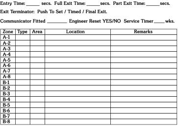
26 APPENDIX 1 System Manager s Organisation Plan List all Users by I.D. number, name, Area Authorisation and Rank (e.g. 07, Mr. Jones, AB, User+) and allow them to set up their own Access Code. Users can make their own arrangements for keeping a permanent record of their Access Code. If you have set up a Duress Code please ensure that users are properly instructed in its use. Allow time to have a full demonstration of your alarm system by the Installation Company s Representative so that you are familiar with the system and can explain it to other users. Take notes relating to any special considerations (e.g. Break Glass Detectors) which may apply to your particular installation and which won t be covered by these instructions. Ensure that the Specification details in the back of this booklet are completed in conjunction with the Alarm Installation Company Remove users from the Code List when they are no longer entitled to access the system. Ensure that all users are able to use the system properly. It may be possible to obtain additional copies of this guide from your alarm company. Have your alarm system regularly serviced and test it yourself at intervals. You can do this without creating a call to the Alarm Receiving Centre. Immediately inform your alarm company of any alarm activations. Layout and building alterations to the protected areas may affect the security of your premises. Always consult with your alarm company before implementing any changes. Engineer On Site The System Manager should confirm the credentials of visiting Engineers before allowing access to the system. It is only possible for an Engineer to access the system if it is fully Unset. To access the system the Engineer will open a Remote Keypad (which will create a Tamper Alarm) and then press the Engineer Button; the Text Display will now show ENTER ENGR. CODE. Once the engineer s Access Code has been entered the Tamper Alarm will be cancelled and all other Remote Keypads will show ENGINEER ON SITE. The system should now be regarded as totally insecure and cannot be used until the Engineer signs off. Printer Option Most installations do not provide the necessary hardware facilities to allow a System Manager to use the printer options; it will be necessary to contact your Alarm Company if you require a printout. If you would like to have yor own printer facility you will need to obtain a JSB Portable Printer. This is specially designed to interface with the JSB Security Data Bus which is common to all JSB security systems.you can plug in a JSB Portable Printer provided that the Control Unit has been fitted with an external printer socket. Alternatively if the Real Time log print option is in operation the printer may have been permanently wired into the installation by your Alarm Company. 24
27
28
2200 and 2200L ALARM CONTROL SYSTEMS
 2200 and 2200L ALARM CONTROL SYSTEMS OPERATING INSTRUCTIONS MODELS: 2200 (fitted software 3.4 or later) 2200L (fitted software 3.9L or later) Castle Care-Tech Ltd. 2200/2200L Alarm System Operating Manual
2000 SERIES DIAGNOSTIC ALARM CONTROL SYSTEM
 2000 SERIES DIAGNOSTIC ALARM CONTROL SYSTEM OPERATING INSTRUCTIONS MODELS: 2300 2500 2700 This information is relevant to systems fitted with Issue 4.1 (or later) Master Keypad Software, also to Networked
8 plus and16 plus. User s Guide * # ent. esc GALAXY 16+ V2.XX TUE 30 JUN. IU ZST 962 Issue 2. A u B u
 8 plus and16 plus User s Guide GALAXY 16+ V2.XX 06.22 TUE 30 JUN 1 2 3 4 5 6 7 8 9 0 * # A u B u ent esc IU1-0018 ZST 962 Issue 2 Contents INTRODUCTION... 1 Glossary of Terms... 3 KEYPAD INFORMATION...
M800, M800iD Plus, M1000 and M3000. User's Guide
 M800, M800iD Plus, M1000 and M3000 User's Guide Cooper Security Limited 2005 Every effort has been made to ensure that the contents of this book are correct. However, neither the authors nor Cooper Security
HARDWIRED CONTROL PANELS
 USER'S GUIDE HARDWIRED CONTROL PANELS Cooper Security Limited 2007 Every effort has been made to ensure that the contents of this book are correct. However, neither the authors nor Cooper Security Limited
HARDWIRED CONTROL PANELS
 USER GUIDE 9651 HARDWIRED CONTROL PANELS Contents 1. Introduction...3 The Alarm System...3 The Keypad...3 About This Guide...5 2. Everyday Operation...6 How Do I Know if the System is Working?...6 Setting
IDS816 User Manual H Issued January 2009
 1 Contents Glossary-------------------------------------------------------------------------------------------------------------------6 1. Introduction to the IDS 816---------------------------------------------------------------------------7
Watchguard WGAP864 User Manual
 Watchguard WGAP864 User Manual v1.0 Issued September 2016 1 2 Table of Contents Glossary... 5 1. Introduction to your Watchguard WGAP864... 6 2. Before Operating your Alarm System... 6 3. Understanding
Contents. Glossary
 Contents Glossary ------------------------------------------------------------------------------------------------------ 6 1. Introduction to the IDS 1632 -------------------------------------------------------------
Warning: Mains voltages are present inside control unit. No user serviceable parts inside.
 Eaton s Security Business. 2014 IN NO EVENT WILL EATON S SECURITY BUSINESS BE LIABLE FOR ANY SPECIAL, CONSEQUENTIAL, OR INDIRECT LOSS OR DAMAGE, INCIDENTAL DAMAGES, STATUTORY DAMAGES, EXEMPLARY DAMAGES,
USER GUIDE HARDWIRED CONTROL PANELS
 USER GUIDE HARDWIRED CONTROL PANELS Scantronic Contents 1. Introduction... 3 The Alarm System... 3 The Keypads... 3 The 725r Remote Setting Device... 6 About This Guide... 6 2. Everyday Operation... 7
Accenta/Optima. User Guide. UK Security Panels. Servicing Organisation (Installer) name: Telephone Number: Date of Installation: Account Number:
 name: Telephone Number: Date of Installation: Account Number:") Accenta/Optima User Guide ZONE 1 2 3 4 5 6 7 8 9 Chime Omit Prog PA 0 1 2 3 4 5 6 7 8 9 CHIME OMIT RESET PROG SET Accenta + TA PA DAY POWER PA! " # $ % & 0 1 2 3 5 6 7 8 Chime Omit Reset Prog 4 9 Set PA
Accenta/Optima User Guide ZONE 1 2 3 4 5 6 7 8 9 Chime Omit Prog PA 0 1 2 3 4 5 6 7 8 9 CHIME OMIT RESET PROG SET Accenta + TA PA DAY POWER PA! " # $ % & 0 1 2 3 5 6 7 8 Chime Omit Reset Prog 4 9 Set PA
Galaxy Flex V3. User Guide. Honeywell Security. This user manual is located at
 Galaxy Flex V3 User Guide Honeywell Security This user manual is located at www.eaglesecuritysolutions.co.uk Contents Introduction... 5 Controlling your alarm system... 6 Users... 6 Panel control... 6
Racal-Guardall. Countess. User Instructions. Countess
 Racal-Guardall Countess User Instructions Countess INCORRECT ACCESS CODES If three incorrect access codes are entered within five minutes a tamper fault will be generated. 1. SETTING FULL SYSTEM Enter
16 and 16 plus User s Guide
 16 and 16 plus User s Guide GALAXY 16+ V2.XX 06.22 TUE 30 JUN 1 2 3 4 5 6 7 8 9 * 0 # A u B u ent esc Contents INTRODUCTION... v QUICK OPERATION GUIDE...vii GLOSSARY OF TERMS... ix KEYPAD INFORMATION...
Intruder alarm system Operating Instructions
 Intruder alarm system Operating Instructions 0 2 3 4 5 6 7 8 9 CHIME OMIT RESET PROG SET S Power 0 2 3 5 6 7 8 Chime Omit Prog 4 9 Set AccentaG3 mini Servicing organisation details Servicing organisation
IDS S E C U R I T Y IDS816. User Manual. MANUAL NO A ISSUED November 2004 VERSION 1.00
 INHEP DIGITAL IDS S E C U R I T Y IDS816 User Manual MANUAL NO. 700-283-02A ISSUED November 2004 VERSION 1.00 Contents 1. Introduction to the IDS816... 4 2. Understanding the Keypad Indicators... 4 3.
IDS S E C U R I T Y IDS816. User Manual MANUAL NO B ISSUED DEC 2004 VERSION 2.00
 INHEP DIGITAL IDS S E C U R I T Y IDS816 User Manual MANUAL NO. 700-283-01 B ISSUED DEC 2004 VERSION 2.00 Contents 1. Introduction to the IDS816... 4 2. Understanding the Keypad Indicators... 4 3. Programmable
U ser's Guide PC6010
 User's Guide PC6010 Quick Reference Guide This manual is for Basic and Advanced users. Each of these types of user can access a different set of functions. The and symbols next to the title of each procedure
User s Guide. SUB-MA7240O-0001.OG.Solution doc. Created: 6/05/03. Last Updated: 23/09/03. MA7240AO-0001 Version 1.0
 User s Guide SUB-MA7240O-0001.OG.Solution40-111.doc Created: 6/05/03 Last Updated: 23/09/03 MA7240AO-0001 Version 1.0 2 Table Of Contents User List...6 Quick Reference..7 Features...7 Keypad User's Guide...8
Introduction. When using an LED keypad for Abacus 6P (or some older Abacus panels) refer to the LED Operator instructions guide (Part No. Y6055).
 refer to the LED Operator instructions guide (Part No. Y6055).") Introduction The Abacus range of intruder alarm panels are manufactured by Detection Systems, using advanced microprocessor technology, this allowing greater flexibility and ease of use. Whilst great care
Introduction The Abacus range of intruder alarm panels are manufactured by Detection Systems, using advanced microprocessor technology, this allowing greater flexibility and ease of use. Whilst great care
IDS S E C U R I T Y IDS816. User Manual MANUAL NO C ISSUED APRIL 2005 VERSION 2.00
 INHEP DIGITAL IDS S E C U R I T Y IDS816 User Manual MANUAL NO. 700-283-01C ISSUED APRIL 2005 VERSION 2.00 Contents 1. Introduction to the IDS816... 4 2. Understanding the Keypad Indicators... 4 3. Programmable
USER GUIDE HARDWIRED CONTROL PANELS
 USER GUIDE HARDWIRED CONTROL PANELS Contents 1. Introduction... 3 The Alarm System... 3 The Keypads... 4 The 725r Telecommand (Remote Setting Device)... 5 About This Guide... 5 2. Everyday Operation...
SECURIT 703 USER MANUAL
 SECURIT 703 USER MANUAL C & K Systems Ltd THE SECURIT 703. USER INSTRUCTIONS VERSION 1.4 September 1996 C031-111-03 1.0 SETTING 1.1 FULL SET To start the exit procedure ensure all alarmed zones are clear
NX-148 LCD CODE PAD TABLE OF CONTENTS
 NX-148 LCD CODE PAD TABLE OF CONTENTS Glossary Of Terms... 4 Understanding The Lights... 5 Code Pad Functions Arming In The ON Mode... 6 Making The System Ready To Arm... 7 Using Quick Arm... 7 Arming
TS2500. Intruder Alarm Control Panel. SYSTEM OPEN 17:30 01 Jan ENT ESC. Setting the System. Unsetting the System RE SET
 E n t er y ou r pa s s c o de X X X X th en l ea v e th e p r o tec t e d a re a. G o dir e ct ly to t h e k e yp ad an d en te r y ou r p as s c o d e X X X X. E n t er y ou r pa s s c o de X X X X f
SECURIT 700L USER MANUAL
 SECURIT 700L USER MANUAL C & K Systems Ltd 6/12/95 Securit 700L User instructions This manual will give you all the information you need to operate and control the Securit 700L Control Panel. This manual
USER GUIDE HARDWIRED CONTROL PANELS
 USER GUIDE HARDWIRED CONTROL PANELS Contents 1. Introduction... 3 The Alarm System... 3 The Keypads... 3 The 725r Telecommand (Remote Setting Device)... 5 About This Guide... 5 2. Everyday Operation...
Scantronic Leading the way in security
 USER GUIDE 808 HARDWIRED CONTROL PANEL Scantronic Leading the way in security Contents 1. Introduction... 3 The 808 System... 3 Using the Keypad... 4 About This Guide... 5 2. Everyday Operation... 6 Setting
Scantronic Leading the way in security
 USER GUIDE (16 ZONE) HARDWIRED CONTROL PANEL Scantronic Leading the way in security Contents 1. Introduction 3 The 9800+ (16 zone) System... 3 The Keypad... 3 About This Guide... 5 2. Everyday Operation
User Guide. Contents. About this guide. i-on Style Security System
 i-on Style Security System User Guide Contents About this guide.... 1 About i-on Style... 2 System components.... 2 Control unit... 2 Detectors... 2 External sirens... 3 Remote controls... 3 HUA transmitters...
Summary of Keypad Main User Commands
 User Manual Summary of Keypad Main User Commands Full Set Code > Part Set Code > System Unset Silence an Alarm Partition Full Set Partition Part Set Code> Code> Code > > Partition No. > Code > > Partition
The Challenger Version 8 User Guide
 The Challenger Version 8 User Guide CONTENTS Function included in your system Introduction...4 Glossary... 6 The Challenger Console.. Liquid Crystal Display... 9 Keypad...10 Indicator Lights...11 User
Security System. User s Guide for the Text Command Center
 User s Guide for the Text Command Center MY ALARM COMPANY IS: CALL BEFORE TEST: THIS SECURITY SYSTEM IS CONNECTED TO TELEPHONE NUMBER: THE SECURITY CONTROL PANEL IS CONNECTED TO THE PHONE JACK LOCATED:
Contents. Glossary Introduction to the IDS Notes Understanding the Keypad Indicators Operation of the Keypad...
 2 Contents Glossary...7 1. Introduction to the IDS805...8 1.1 Notes...8 2. Understanding the Keypad Indicators...8 3. Operation of the Keypad...9 4. System Information...10 4.1 Programmed Functions...10
QUICK CONSUMER REFERENCE GUIDE
 QUICK CONSUMER REFERENCE GUIDE YOUR System: Galaxy 16+ / 8+ Setting Your System When leaving your home ensure that all protected doors/windows, including your front door, are closed before setting your
Advisor Advanced User Guide
 Advisor Advanced User Guide P/N 1068996 (EN) REV G ISS 28AUG15 Copyright Trademarks and patents Manufacturer Version Certification 2015 UTC Fire & Security Americas Corporation, Inc. All rights reserved.
Control Panel User Guide
 Fire Detection & Alarm System Control Panel V4.14 Control Panel User Guide (TO BE RETAINED BY USER) 26-0397 Issue 6 Fike s policy is one of continual improvement and the right to change a specification
i on Compact Security System
 i on Compact Security System Administration and User Manual Issue 1 Control unit software version 5.03 Eaton 2017 The information, recommendations, descriptions and safety notations in this document are
Security System With Scheduling. User Guide. N5943-8V4 7/04 Rev A
 ADEMCO VISTA-120 Security System With Scheduling User Guide N5943-8V4 7/04 Rev A Your Honeywell security system is designed for use with devices manufactured or approved by Honeywell for use with your
Table of Contents. Appendix A Special Characters 31
 Table of Contents Introduction 2 Section 1: General System Operation 3 1.1 Getting to Know Your System... 3 1.2 How to Arm... 4 1.3 Alternate Arming Methods... 5 1.4 Disarming... 6 1.5 Alarm Memory...
Euro ONE. RENDER ALARMS Your security, above all else. User Manual. t: f:
 Euro ONE User Manual RENDER ALARMS Your security, above all else t: 01642 230695 f: 01642 252399 You ve Made the Right Choice Contents Introduction 1-5 Using EURO Panel with Code or Tag 6-7 Intelligent
SECURIT 700L PLUS ENGINEERING MANUAL
 SECURIT 700L PLUS ENGINEERING MANUAL C & K Systems Ltd 13/03/97 C031-096-02 NEW ENHANCED FEATURE SET Securit 700L PLUS Engineering instructions INTRODUCTION The Securit 700L is a microprocessor intruder
TS400 & TS410. Intruder Alarm Control Panels. Operating Instructions
 TS400 & TS410 Intruder Alarm Control Panels Operating Instructions Zone Location Home Set Chime 1 Armed / Omitted 2 Armed / Omitted 3 Armed / Omitted 4 Armed / Omitted 5 Armed / Omitted F. Exit Always
Elite 16D Version 16 Zone Controller Arrowhead Alarm Products Ltd. Operating Guide. Proudly Designed and Manufactured in New Zealand
 6 Elite 16D Version 16 Zone Controller Arrowhead Alarm Products Ltd Operating Guide 1 Proudly Designed and Manufactured in New Zealand CONTENTS Page No. INTRODUCTION 3 About your Alarm 3 OPERATING YOUR
NetworX Series NX-1500E LED Keypad
 NetworX Series NX-1500E LED Keypad User Manual SECURITY SYSTEM NOTES Installing/Service Company For Service Call Central Station Duress Code FUNCTION CODES Function Code Controls Function This system
2000 Series. Program Entry Guide. Control Panels
 2000 Series EN Program Entry Guide Control Panels 2000 Series Program Entry Guide About This Manual EN 2 About This Manual This guide describes the programming parameters available to the 2000 Series Control
Welcome to. Welcome to Security and Peace of Mind CASTLE CARE TECH CARE TECH CARE TECH CARE TECH
 Welcome to Welcome to Security and Peace of Mind CARE TECH CARE TECH CARE TECH CASTLE CARE TECH Contents Introduction A1-3 Using Meridian with your PIN Code B1-7 Using Meridian with your Tag C1-8 When
ALARM SYSTEM USER GUIDE
 ALARM SYSTEM USER GUIDE Issue 2 Compliance Statements... iii 1. Introduction... 1 Alarm System... 1 Keypad... 2 Proximity Tags... 2 Mains Power Failures... 4 About this Guide... 4 2. Everyday Operation...
Alarm Control Panel WIC-16Z4P WIC-5Z2P. User Instructions
 WIC-16Z4P WIC-5Z2P User Instructions Page : 2/14 INDEX # Function Page 1 Add a New User Code 11 2 Arm or Disarm All Areas or Disarm Selected Areas (Partitioned System) 8 3 Arming the System (Away Mode)
ABORT Light flashes during an abort delay time; is on during or after an alarm report to the central station. EMERGENCY ACTIVATION KEYS
 POWER Light is on when AC power is present; flashes to indicate a low battery condition. CHIME Light is on when the chime feature is active. ABORT Light flashes during an abort delay time; is on during
NetworX NX-8V2. LED Keypad User Manual
 NetworX NX-8V2 LED Keypad User Manual POWER Light is on when AC power is present; flashes to indicate a low battery condition. ARMED Light is on when armed; off when disarmed; flashes to indicate a previous
Understanding the Code Pad lights...4. Code Pad tones...5. Fully arming the system On MODE...6. Fully arming the system - Quick Arm MODE...
 TABLE OF CONTENTS...Glossary of terms...2...code Pad Diagram...3 Understanding the Code Pad lights...4 Code Pad tones...5 Fully arming the system On MODE...6 Fully arming the system - Quick Arm MODE...6
ZX1e ZX2e ZX5e. Document No Issue 01 user manual
 ZX1e ZX2e ZX5e Document No. 996-130 Issue 01 user manual MORLEY-IAS ZX2E/ZX5E Fire Alarm Control Panels Table of Contents 1 INTRODUCTION... 4 1.1 NOTICE... 4 1.2 WARNINGS AND CAUTIONS... 4 1.3 NATIONAL
Security System. User Guide for the LED Command Center
 Security System User Guide for the LED Command Center National Security Systems Inc (800)457-1999 MY SECURITY COMPANY IS: CALL BEFORE TEST: THIS SECURITY SYSTEM IS CONNECTED TO TELEPHONE NUMBER: THE SECURITY
Operating instructions SENTRI4 Control panel based Fire detection and alarm system
 1 2 3 4 5 6 7 8 9 10 11 12 13 14 15 16 17 18 19 20 21 22 23 24 25 26 27 28 29 30 30 32 Zones Healthy 15:45 Fault Power Fault System Fault SenTRI 4 Fire System Designed to EN54 Pt 2 & 4 Operating instructions
Using Your. Security System With LED Keypad S5030, S5031, S5032
 Using Your Security System With LED Keypad S5030, S5031, S5032 Contents 1 Overview Your Security System... 1 How Your Security System Works... 2 Your System's Programming... 3 Getting Used to Your System...
AXI LED USER MANUAL (REV. 1.0)
") Security & Home Automation System AXI LED USER MANUAL (REV. 1.0) CONTENTS PREFACE FEATURES LED KEYPAD OUTLOOK 1.0 LIGHT INDICATION 1 2 4 6 CHAPTER 1: ALARM SYSTEM CONTROL 1.0 USING LED KEYPAD 1.0.1 ARMING
Security & Home Automation System AXI LED USER MANUAL (REV. 1.0) CONTENTS PREFACE FEATURES LED KEYPAD OUTLOOK 1.0 LIGHT INDICATION 1 2 4 6 CHAPTER 1: ALARM SYSTEM CONTROL 1.0 USING LED KEYPAD 1.0.1 ARMING
BENTEL SECURITY srl reserves the right to modify the technical specifications of this product without prior notice.
 BENTEL SECURITY srl reserves the right to modify the technical specifications of this product without prior notice. via Florida - Z.I. Valtesino - 63013 GROTTAMMARE (AP) - ITALY USER MANUAL: Digital communicator
IDS800 USER MANUAL. Summary of Operation. + [ ] 2 IDS800 USER MANUAL NO K ISSUED APR 2003 VER 1.44
![IDS800 USER MANUAL. Summary of Operation. + [ ] 2 IDS800 USER MANUAL NO K ISSUED APR 2003 VER 1.44](/thumbs/89/98095999.jpg "IDS800 USER MANUAL. Summary of Operation. + [ ] 2 IDS800 USER MANUAL NO K ISSUED APR 2003 VER 1.44") Summary of Operation A rm/ disarm [#] + [USER CODE] Quick Quick Quick Away Arm Stay Arm Stay Arm & Go H old down [ 1] for 1 second H old down [ 5] for 1 second H old down [ 6] for 1 second Panic Fire Medical
Summary of Operation A rm/ disarm [#] + [USER CODE] Quick Quick Quick Away Arm Stay Arm Stay Arm & Go H old down [ 1] for 1 second H old down [ 5] for 1 second H old down [ 6] for 1 second Panic Fire Medical
NETWORX TM. User manual NX-4
 NETWORX TM User manual NX-4 POWER Light is on when AC power is present; flashes to indicate a low battery condition. ARMED Light is on when armed; off when disarmed; flashes to indicate a previous alarm.
Master User Guide Premier Elite Series
 Master User Guide Premier Elite Series INS177-9 Overview Premier Elite Series Master User Guide Contents 1. Overview... 5 Introduction... 5 Keypads... 7 Emergency Keys... 8 The Quick Arm Keys... 9 Keypad
Fusion Alarm System USER GUIDE
 Fusion Alarm System USER GUIDE 020009599 CONTENTS Arming Menu 3 Full Set 3 Disarm 4 Instant Full Set 4 Part Set 5 System fails to set 5 System Alerts 6 Disarming after an alarm, Call Central Station 7
Digiplex LED Keypads User s Manual
 KLEDEU03.fm Page -1 Friday, May 4, 2001 11:25 AM Digiplex LED Keypads User s Manual KLEDEU03.fm Page 0 Friday, May 4, 2001 11:25 AM KLEDEU03.fm Page 1 Friday, May 4, 2001 11:25 AM TABLE OF CONTENTS 1.0
Elite 64 Version 64 Zone Controller Arrowhead Alarm Products Ltd. Operating Guide. Proudly Designed and Manufactured in New Zealand
 2 Elite 64 Version 64 Zone Controller Arrowhead Alarm Products Ltd Operating Guide Proudly Designed and Manufactured in New Zealand 1 CONTENTS Page No. INTRODUCTION 3 About your Alarm 3 OPERATING YOUR
DS7446KP. User Guide. Keypad
 DS7446KP EN User Guide Keypad DS7446KP User Guide Command Quick Reference Command Quick Reference Command Type Basic Arming Commands Advanced Arming Commands System Disarming Commands Command Turn the
Maintenance Manual PC6010. WARNING This manual contains information on limitations regarding product use and function
 WARNING This manual contains information on limitations regarding product use and function and information on the limitations as to liability of the manufacturer. The entire manual should be carefully
one Operating instructions SenTRI ONE panel-based Fire detection and alarm system
 SenTRI ONE panel-based Fire detection and alarm system one 042bc/14 4188-978 issue 2_04-10_SenTRI ONE system oper Part of Document pack 2535-235 issue 2 1 Contents User responsibility - - - - - - - - -
USER MANUAL CEF AP28 CONTROL PANEL
 USER MANUAL CEF AP28 CONTROL PANEL AP28 WARNINGS This product has mains voltage present within the housing. Please take the necessary precautions in not allowing any liquid to spill on or into the housing.
User s Information Guide R2A
 Pi HSC505 Home Security Controller User s Information Guide R2A Page 1 of 15 of its development program. 1This document and product are copyrighted and all rights are reserved. Introduction Convention
The most user friendly Security Alarm System L S Section 1 Overview of System Section 2 Planning your Installation
 The most user friendly Contents Section 1 Overview of System 1.1 Kit Contents 1.2 Tools Required 1.3 System Features Security Alarm System L S 4 0 0 Section 2 Planning your Installation 2.1 Location of
THANK YOU FOR VOTING TEXECOM THANK YOU FOR VOTING TEXECOM USER GUIDE. Security Control Panels 1 INS167
 Veritas User Guide Quick Reference Guide THANK YOU FOR VOTING TEXECOM THANK YOU FOR VOTING TEXECOM USER GUIDE Security Control Panels 1 INS167 Overview Premier Series User Guide 1. Overview Introduction
OPERATING GUIDE FOR YOUR RP1054D KEYPAD
 OPERATING GUIDE FOR YOUR RP1054D KEYPAD Napco 1992 DESIGN PATS. PENDING Technical Manuals Online! - http://www.tech-man.com CONGRATULATIONS!...on your purchase of a NAPCO Magnum Alert security system.
Syncro AS. Analogue Addressable Fire Control Panel. User Manual
 Syncro AS Analogue Addressable Fire Control Panel User Manual Man-1100 Issue 02 Nov. 2008 Index Section Page 1. Introduction...3 2. Safety...3 3. Panel Controls...4 3.1 Access Level 1...4 3.2 Access Level
Fire detection and alarm system Operating instructions
 Fire detection and alarm system Operating instructions Operating instructions Table of Contents User responsibility - - - - - - - - - - - - 4 Daily - - - - - - - - - - - - - - - - - - - 4 Weekly - - -
&RPPHUFLDO%XUJODU\ 3DUWLWLRQHG6HFXULW\6\VWHP ZLWK6FKHGXOLQJ
 READY ARMED READY 1 OFF 7 INSTANT READY 2 AWAY 8 CODE 6BYPASS 9 CHIME 9,67$% &RPPHUFLDO%XUJODU\ 3DUWLWLRQHG6HFXULW\6\VWHP ZLWK6FKHGXOLQJ 8VHU*XLGH ARMED READY 1 OFF 2 AWAY 3 STAY 4 MAX 5 TEST 6 BYPASS
EURO 46 User Manual. For use with EURO 46 (version 9.1 or above) RINS1531-2
 RINS1531-2") EURO 46 User Manual For use with EURO 46 (version 9.1 or above) RINS1531-2 Contents Introduction 1 Using EURO Panel with Code or Tag 7-9 Intelligent Setting 13 Silencing the Alarm 20 Setting Individual
EURO 46 User Manual For use with EURO 46 (version 9.1 or above) RINS1531-2 Contents Introduction 1 Using EURO Panel with Code or Tag 7-9 Intelligent Setting 13 Silencing the Alarm 20 Setting Individual
SECURITY SYSTEM NOTES
 SECURITY SYSTEM NOTES Installing/Service Company For Service Call Central Station Duress Code FUNCTION CODES Function Code Controls Function EMERGENCY ACTIVATION KEYS (check if enabled) Fire Auxiliary
VISTA-32FBPT. Commercial Fire and Burglary Partitioned Security Systems with Scheduling. User Guide /12 Rev. B
 VISTA-32FBPT Commercial Fire and Burglary Partitioned Security Systems with Scheduling User Guide 800-11045 2/12 Rev. B 2 TABLE OF CONTENTS SYSTEM OVERVIEW...5 General...5 A Partitioned System...5 Zones...6
Elite S Version 8-16 Zone Controller Arrowhead Alarm Products Ltd. Operating Guide. Proudly Designed and Manufactured in New Zealand
 9 Elite S Version 8-16 Zone Controller Arrowhead Alarm Products Ltd Operating Guide Proudly Designed and Manufactured in New Zealand 1 CONTENTS Page No. INTRODUCTION About your Alarm 3 3 OPERATING YOUR
&RPPHUFLDO)LUHDQG%XUJODU\ 3DUWLWLRQHG6HFXULW\6\VWHP ZLWK6FKHGXOLQJ
LUHDQG%XUJODU\ 3DUWLWLRQHG6HFXULW\6\VWHP ZLWK6FKHGXOLQJ") 9,67$)% &RPPHUFLDO)LUHDQG%XUJODU\ 3DUWLWLRQHG6HFXULW\6\VWHP ZLWK6FKHGXOLQJ 8VHU*XLGH FIRE FIRE * PULL K3522 3/99 TABLE OF CONTENTS SYSTEM OVERVIEW...4 General...4 A Partitioned System...4 Zones...5 Fire
9,67$)% &RPPHUFLDO)LUHDQG%XUJODU\ 3DUWLWLRQHG6HFXULW\6\VWHP ZLWK6FKHGXOLQJ 8VHU*XLGH FIRE FIRE * PULL K3522 3/99 TABLE OF CONTENTS SYSTEM OVERVIEW...4 General...4 A Partitioned System...4 Zones...5 Fire
&RPPHUFLDO%XUJODU\ 3DUWLWLRQHG6HFXULW\6\VWHP ZLWK6FKHGXOLQJ
 READY ARMED READY 1 OFF 7 INSTANT 2 AWAY 8 CODE 6BYPASS 9 CHIME 9,67$%3 9,67$%3 &RPPHUFLDO%XUJODU\ 3DUWLWLRQHG6HFXULW\6\VWHP ZLWK6FKHGXOLQJ 8VHU*XLGH ARMED READY 1 OFF 2 AWAY 3 STAY 4 MAX 5 TEST 6 BYPASS
Destiny Destiny Owners Manual
 Destiny 4100 Destiny 4100 Owners Manual TABLE OF CONTENTS INTRODUCTION Control Panel...3 Detection Devices...3 Telephone Keypads...3 GLOSSARY... 4-5 LOCAL PHONE ACCESS Using Your Telephones As Keypads...6
Control Panel User Guide (TO BE RETAINED BY THE USER)
") Fire Detection & Alarm System Control Panel V3 (Suitable for Quadnet control panels from V2.00) Control Panel User Guide (TO BE RETAINED BY THE USER) 26-0585 Issue 7 Fike s policy is one of continual improvement
Fire Detection & Alarm System Control Panel V3 (Suitable for Quadnet control panels from V2.00) Control Panel User Guide (TO BE RETAINED BY THE USER) 26-0585 Issue 7 Fike s policy is one of continual improvement
GE Security. Challenger V8 & V9. User Manual
 GE Security Challenger V8 & V9 User Manual Copyright Disclaimer Trademarks and patents Intended use Copyright 2008, GE Security Pty. Ltd.. All rights reserved. This document may not be copied or otherwise
Protégé Eclipse LED Keypad User Manual PRT-KLES
 Protégé Eclipse LED Keypad User Manual PRT-KLES The specifications and descriptions of products and services contained in this manual were correct at the time of printing. Integrated Control Technology
Intelligent Security & Fire Ltd. PX Control Panel. User Manual. Issue C
 PX Control Panel User Manual Issue C Contents CONTENTS...2 INTRODUCTION...5 EVENT LOG...5 AREAS & SET GROUPS...5 CIRCUITS...5 USER, SET GROUP AND CIRCUIT IDENTIFICATION...6 USER CODES...6 OPERATOR CONTROLS
D6500 reports are shown in typewriter style letters. For example, AC FAILED indicates the report sent when the panel reports an AC power failure.
 Notice The material and instructions covered in this manual have been carefully checked for accuracy and are presumed to be reliable. However, Radionics, Inc. assumes no responsibility for inaccuracies
**** **** A B ARMED FIRE FIRE C D READY OFF AWAY STAY 2 3 MAXIMUM TEST BYPASS PULL INSTANT CODE CHIME. First Alert READY. * 0 # Professional
 ARMED READY READY )$&&$&% )LUHDQG%XUJODU\ 3DUWLWLRQHG6HFXULW\6\VWHPV ZLWK6FKHGXOLQJ **** **** A B C D FIRE FIRE First Alert OFF AWAY STAY 2 3 1 4 5 6 7 8 9 MAXIMUM TEST BYPASS INSTANT CODE CHIME * 0 #
/10 Rev A
 VISTA-128BPT/ VISTA-250BPT/ VISTA-128BPTSIA Commercial Burglary Partitioned Security System With Scheduling User Guide 800-06905 6/10 Rev A Your Honeywell security system is designed for use with devices
2) This manual covers Fire and General Alarm systems. The differences are described in the appropriate sections.
 This manual covers Fire and General Alarm systems. The differences are described in the appropriate sections.") ISSUES ISSUE DATE RELEASED DETAILS OF CHANGE AUTHOR 4 Rev 2 September 2004 Changes for 4000 series. DB 4 Rev 3 April 2005 Screen shots updated and other minor changes K.Z. 4 Rev 4 September 2006 4 Rev
ISSUES ISSUE DATE RELEASED DETAILS OF CHANGE AUTHOR 4 Rev 2 September 2004 Changes for 4000 series. DB 4 Rev 3 April 2005 Screen shots updated and other minor changes K.Z. 4 Rev 4 September 2006 4 Rev
EURO User Manual. For use with EURO 76, MSX 162, MSX 280 software: Version 9.1 or above RINS1527-2
 EURO User Manual For use with EURO 76, MSX 162, MSX 280 software: Version 9.1 or above RINS1527-2 You ve Made the Right Choice Contents Introduction 1-6 Using EURO Panel with Code or Tag 7-8 Intelligent
TS700. Intruder Alarm Control Panel OPEN ENT 0 ESC
 TS700 Intruder Alarm Control Panel OPEN _ ~ A 1 2 3 B 4 5 6 C 7 8 9 D ENT 0 ESC Setting the System Ent er your pa sscode XXXX then leave the protected area. Unsetting the System Go directly to the keypad
Ref. 1067/024 Ref. 1067/032A Ref. 1067/052A
 DS1067-062C Mod. 1067 LBT20063 REMOTE CONTROLLABLE ALARM CONTROL PANELS Ref. 1067/024 Ref. 1067/032A Ref. 1067/052A USER MANUAL TABLE OF CONTENTS INTRODUCTION... 6 1 CONTROL DEVICES... 7 1.1 1067/022 keypad
Version 1.03 January-2002 USER S MANUAL
 Version 1.03 January-2002 1 USER S MANUAL 2 Version 1.03 January-2002 System Details CUSTOMER:...... PHONE:... FAX:... INSTALLED BY:...... PHONE:... FAX:... MAINTENANCE & SERVICE:...... PHONE:... FAX:...
THANK YOU FOR VOTING TEXECOM USER GUIDE. Security Control Panels
 THANK YOU FOR VOTING TEXECOM USER GUIDE Security Control Panels User Guide Summary User Guide Summary Full Set Press Full " Part Set Press Part Set Number # or $ Press Part % Unset Omit Zones Press Full
QUICK USER GUIDE. Alarm Control Panel
 Alarm Control Panel Firmware version 2.10 QUICK USER GUIDE The full version of User Manual and other manuals are available on CD included in the control panel delivery set or on the website www.satel.eu
Solution Ultima Series Operators Manual ISSUE 1.00
 Solution Ultima Series Operators Manual ISSUE 1.00 Solution Ultima Series Operators Manual Copyright 1998 by, SYDNEY, AUSTRALIA Document Part Number MA488O DOCUMENT ISSUE 1.00 Printed 16 February 1999
6100 SINGLE LOOP DIGITAL ADDRESSABLE FIRE ALARM CONTROL PANEL
 6100 SINGLE LOOP DIGITAL ADDRESSABLE FIRE ALARM CONTROL PANEL USER MANUAL Protec Fire Detection plc, Protec House, Churchill Way, Nelson, Lancashire, BB9 6RT. Telephone: +44 (0) 1282 717171 Fax: +44 (0)
Table of Contents About This User s Guide... 2 Introduction... 2 Security System Basics... 3 What is a Point?... 3 What is a Faulted Point?...
 Table of Contents About This User s Guide... 2 Introduction... 2 Security System Basics... 3 What is a Point?... 3 What is a Faulted Point?... 3 Are All Points the Same?... 3 Controlled Points... 4 24-Hour