Safety Manual. XNX TM Universal Transmitter. Table of Contents SIL 2 Certificates Overview Safety Parameters
|
|
|
- Marian Carson
- 5 years ago
- Views:
Transcription


1 XNX TM Universal Transmitter Safety Manual Table of Contents SIL 2 Certificates Overview Safety Parameters Fault Diagnostic Time Interval Proof Test Proof Testing Procedure
2
3 Table of Contents 1 SIL 2 Certificate XNX Gas Detector Transmitter Overview Safety Parameters Interval of Proof Testing Fault Diagnostic Time Interval Proof Test Purpose of Proof Testing Expected Outcome of Proof Testing Tolerance of Output Current Levels Proof Testing Procedure Checking Force ma Output Zero Gas ma Output Calibration Gas ma Output Adjusting Calibrate 4.0 ma and 20.0 ma Zero Gas Calibration and Span Calibration Zero Gas Calibration Span Calibration Verifying ma Settings Testing Fault and Alarm State Gas Verification

4 1 SIL 2 Certificate 1.1 XNX Gas Detector Transmitter SIL 2 Certificate 4 XNX Gas Detector Transmitter
5 2 Overview IEC is a generic functional safety standard. Functional safety is defined in this standard as part of the overall safety relating to the Equipment Under Control (EUC) and the EUC control system which depends on the correct functioning of the E/E/PES 1 safety related systems, other technology safety-related systems, and external risk reduction facilities. A system is considered to be functionally safe if the random and systematic faults do not kill or injure humans, pollute the environment, and do not result in the loss of equipment or production. A systematic fault is defined as a failure with a definite cause. A random fault can happen at any time and the cause is unclear. The terms fault and failure can be used interchangeably. A Safety Integrity Level-certified system can detect the majority of safe and unsafe failures. XNX is SIL 2 capable per IEC XNX is SIL 3 capable in a redundant system per IEC Table 1 and Table 2 below outline a system s safety integrity level in relation to its average probability of failure to perform its design function on demand and probability of dangerous failure per hour. Table 1. Average Probability of Failure to Perform Its Design Function on Demand (Low Demand System) Safety Integrity Level Low demand mode of operation (Average probability of failure to perform its design function on demand (PFD)) to < to < to < to < 10-1 Safety Integrity Level Table 2. Probability of a Dangerous Failure Per Hour (High Demand System) High demand or continuous mode of operation (Probability of a dangerous failure per hour (PFH)) to < to < to < to < 10-5 NOTE: The XNX system is Type B. A Type B system uses controllers or programmable logic per IEC The XNX product consists of a main board, a personality board, and a sensor. XNX main board XNX Transmitter IR Personality board mv Personality board EC Personality board Note: Only one personality board per XNX main board Sensor IR sensor mv sensor EC sensor This manual outlines the proof test procedure, a required operation to maintain the XNX s functional safety under low demand applications. 1 Electrical/electronic/programmable electronic systems Overview 5 XNX Gas Detector Transmitter
6 3 Safety Parameters The safety parameters listed below are a combination of the main board, personality board, and sensor. These numbers were provided by TUV in report 968/EL /09 (personality boards) and report 968/EZ /09 (main board). For safety parameters of the individual sensors, refer to the XNX Safety Parameters For Sensors white paper. Component XNX Universal Transmitter with Combustible Sensor (IR board) SIL Level* Safety Architecture PFDavg** PFH (1/h) SFF % DC % Test Report SIL2 1oo1 2.7E E >90% λ (fit) λdu (fit) λdd (fit) λd (fit) SC PTC % TUV 968/EZ /15 TUV 968/EL /09 Component XNX Universal Transmitter with Combustible Sensor (mv Catalytic bead) Sensepoint and Sensepoint HT detector SIL Level* Safety Architecture PFDavg** PFH (1/h) SFF % DC % Test Report SIL2 1oo1 4.8E E >90% λ (fit) λdu (fit) λdd (fit) λd (fit) SC PTC % TUV 968/EZ /15 TUV 968/EL /09 Component XNX Universal Transmitter with Toxic Sensor SIL Level* Safety Architecture PFDavg** PFH (1/h) SFF % DC % Test Report SIL2 1oo1 2.5E E >90% λ (fit) λdu (fit) λdd (fit) λd (fit) SC PTC % TUV 968/EZ /15 -- Component XNX Universal Transmitter with Oxygen Sensor SIL Level* Safety Architecture PFDavg** PFH (1/h) SFF % DC % Test Report SIL2 1oo1 2.5E E >90% λ (fit) λdu (fit) λdd (fit) λd (fit) SC PTC % TUV 968/EZ /15 TUV 968/EZ /11 continued... Safety Parameters 6 XNX Gas Detector Transmitter
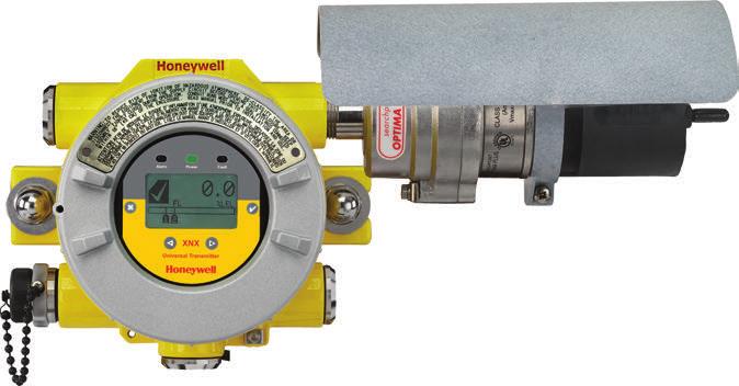
7 Component XNX Universal Transmitter with Infrared Combustible Gas Detector (with Searchpoint Optima Plus) SIL Level* Safety Architecture PFDavg** PFH (1/h) SFF % DC % Test Report SIL2 1oo1 4.8E E >81% λ (fit) λdu (fit) λdd (fit) λd (fit) SC PTC % TUV 968/EZ /15 TUV 968/EZ /12 Component XNX Universal Transmitter with Infrared Combustible Gas Detector (with Searchline Excel) Safety SIL Level* PFDavg** PFH (1/h) SFF % DC % Test Report Architecture SIL2 1oo1 7.7E E TUV 968/EZ /15 λ (fit) λdu (fit) λdd (fit) λd (fit) SC PTC % Exida 04/08-13 R Component XNX Universal Transmitter Standalone XNX Transmitter (main board) SIL Level* Safety PFDavg** Architecture PFH (1/h) SFF % DC % Test Report SIL2 1oo1 1.2E E >90% λ (fit) λdu (fit) λdd (fit) λd (fit) SC PTC % TUV 968/EZ / *This rating is highest achievable SIL level the XNX, Searchpoint Optima Plus gas detection system can achieve as standalone safety devices. In more complex safety system the above values are the safety parameters of XNX and Optima gas detection system required to determine the acceptance of the complete safety function (i.e., all safety parameters, safety architecture, etc.) as required by IEC and IEC **Denotes a proof test interval of one year. 3.1 Interval of Proof Testing If the XNX is used in high demand systems, a proof test is not required. If the XNX is used in low demand systems (defined as 1 demand or less per year) a proof test is required. Perform the proof test once a year to comply with IEC Section 6 Proof Testing Procedure outlines the actions that must be completed for a proof test. 4 Fault Diagnostic Time Interval XNX conducts approximately 30 diagnostics total on the main board and personality board. These diagnostics occur at different time intervals, with the longest interval at 24 hours. But when a fault is detected, it is reported within 3 seconds. Refer to the XNX Technical Manual for more information on diagnostics. Fault Diagnostic Time Interval 7 Interval of Proof Testing
8 5 Proof Test 5.1 Purpose of Proof Testing A proof test is a periodic test to detect failures in the system so that, if necessary, the system can be restored to an as new condition or as close as practical to this condition. 5.2 Expected Outcome of Proof Testing The following features are checked and adjusted if required current output at different levels (4.0 ma and 20.0 ma) verifying zero gas and span gas calibration current output verifying current output of warnings and faults simulating warnings and faults validation of the current output of zero gas and/or span gas calibration (required if the current output of zero gas and/or span gas calibration had to be changed) 5.3 Tolerance of Output Current Levels The tolerance for the output current levels is ± 0.1 ma. Example: If the procedure requires the current output to be 4.0 ma, the actual current reading at the controller end can range from 3.9 ma to 4.1 ma. 6 Proof Testing Procedure 6.1 Checking The purpose of checking is to ensure the ma output meets the expected levels. If the current does not meet the expected levels, it will have to be adjusted. If, after completing 6.1.1, 6.1.2, and 6.1.3, the ma output does meet the expected levels, proceed to Force ma Output 1. Ensure the current can be measured at the controller end. The current will be measured using the procedures outlined in to From the Main Menu, select the Test Menu ( ). CAUTION The ma output set in this menu will revert to the normal operating values when exiting the Test Menu. For more information on setting the ma output levels for normal operation, see ma Levels in the XNX Technical Manual. 3. From the Test Menu, select Force ma Output ( ). The New ma Output screen shows the existing ma output in the left column. The user can adjust the output by changing the value in the column on the right. Figure 1. New ma Output Screen 4. Ensure the current at the controller end is 4.0 ma. If the current is not 4.0 ma, refer to to adjust the output. 5. Repeat steps #2-4 to check the output of 20.0 ma. Proof Test 8 Purpose of Proof Testing

9 6.1.2 Zero Gas ma Output The procedure for zero gas is not applicable to the ECC O 2 sensor. 1. Apply zero gas to the sensor. 2. The current at the controller end should be 4.0 ma. If the ma output is not at the expected level when applying zero gas, perform a Zero Gas Calibration. Refer to and complete the procedure for a Zero Gas Calibration Calibration Gas ma Output 1. Apply calibration gas to the sensor. 2. The current measured at the controller end is related to the percentage of gas applied. Example: 100% of full gas concentration is equivalent to 20.0 ma. If 75% of the full scale gas concentration is applied, the ma output should be 16.0 ma. If the ma output is not at the expected level when applying calibration gas, refer to and perform a Zero Gas Calibration and a Span Gas Calibration. 6.2 Adjusting Perform the following procedures if 4.0 ma and 20.0 ma were not measured at the controller end. If the correct currents were measured, proceed to 6.3. The current must be measured at the controller end in and Calibrate 4.0 ma and 20.0 ma 1. From the Main Menu, select the Test Menu ( ). 2. Then select Force ma output ( ). 3. Adjust the current output in the column on the right until the current at the controller end is 4.0 ma. Figure 2. Adjusting Current 4. Once the new value is entered, use the switches to move to the 3 and select to set the ma output. If the 20.0 ma output was not equal to 20.0 ma, complete steps # Zero Gas Calibration and Span Calibration The following section outlines the steps for calibrating the attached XNX sensors. For calibration information for specific sensors, refer to the XNX Technical Manual. 1. If using a compressed gas cylinder, push the calibration gas flow housing onto the bottom of the sensor and apply the gas. 2. Access the Calibration Menu. Figure 3. Gas Calibration Menu NOTE: The Gas Calibration Menu is for both Zero Gas and Span Gas Calibration. Proof Testing Procedure 9 Adjusting


10 Zero Gas Calibration Sensor Reading at Current Settings Figure 4. Zero Gas Calibration Screen As the sensor detects the zero gas and the concentration increases, the values displayed will reflect the changing concentration. When the concentration values are stable select to allow the XNX to calculate the zero adjustment. Selecting will return to the Gas Calibration Menu Span Calibration NOTE: If a Span Calibration is not required, select to skip the Span Calibration and return to the Calibration Menu. 1. When the Zero Gas Calibration is complete, the Span Concentration screen appears. The gas concentration for the Span Gas Calibration can be changed. If the Span Calibration is skipped, the Gas Calibration screen displays. Figure 5. Zero Gas Calibration in Progress 3. If the Zero Gas Calibration is successful, the Zero Passed screen displays. Figure 7. Span Gas Concentration Screen 2. Enter the concentration of the span gas by selecting to choose the first digit and use the switches to increment or decrement the values. Use to accept the new value and move to the next digit. Continue until all digits have been selected. Sensor Reading at Current Settings Calibration Gas Concentration Figure 6. Zero Gas Calibration Passed Figure 8. Span Calibration Screen 3. Apply the span gas. As the sensor detects the gas and the concentration increases, the values displayed will reflect the changing concentration. When the concentration values are stable select to perform the span. The Span Calibration process also determines whether the sensor is within the proper range to accurately detect the target gas. Proof Testing Procedure 10 Adjusting


. From the Configure Menu, select ma Levels. Figure 10.")
11 Selecting will cancel the span calibration and return to the Gas Calibration Menu. 4. When the sensor has completed the calibration and the span algorithms have determined that it is within range, the Span Passed screen will appear. Figure 9. Span Passed Screen If the calibration is not successful, the Span Failed screen will display. Selecting will return to the Span Concentration screen to begin the span calibration again. Selecting will exit Span Calibration and return to the Gas Calibration Menu. Figure 11. Exiting Zero Gas and Span Gas calibrations WARNING While XNX is in Inhibit Mode, alarms are silenced. This will prevent an actual gas event from being reported. Inhibit Mode must be reset after testing or maintenance activities. 6.3 Verifying ma Settings The ma levels output for inhibiting alarms during maintenance/testing, warnings triggered by the XNX, overrange conditions, Beam Blocked and Low Signal for the Searchpoint Optima Plus and Searchline Excel gas detectors must be verified. 1. From the Main Menu, select the Configure Menu ( ). From the Configure Menu, select ma Levels. Figure 10. Span Calibration Failed Once the Zero Gas and Span Gas calibrations are completed successfully, the user will be prompted to exit with inhibit off, exit with inhibit on, or not exit. Figure 12. ma Levels Menu 2. Use the switches to move to the ma output to be changed and use to select it. Figure 13. Set ma Levels for Warning Proof Testing Procedure 11 Verifying ma Settings


12 3. Refer to Table 6 for the ma levels. If the values do not match the values in the table, proceed to step #4 to adjust the values. NOTE If the values for the faults and warnings have been changed from the default settings since installation, ensure the current output matches those changed values. Table 3. Set ma Levels Signal* Output (ma) Default Min Max I Inhibit 2.0 ma W Warning 3.0 ma O Overrange 21.0 ma B** Beam Blocked 1.0 ma L** Low Signal 1.0 ma *Faults are set to 1 ma and are not user-selectable **Beam blocked and Low Signal apply only to Excel sensors. 4. Using the switches, increment or decrement the value until the desired value appears. Then use to confirm the value and move to the next setting. Repeat for each setting that must be changed. The available output range for Inhibit, Warning, Beam Blocked and Low Signal is from 1.0 to 4.0 ma and for an overrange condition, the range is 20.0 to 22.0 ma. Refer to Section 5 Warnings/Faults in the XNX Technical Manual for more information. 5. Once all changes have been made, use the switches to move to the 3 and use on the front panel to save the settings. Figure 14. ma Settings Saved NOTE: If 3 is not selected, none of the changes will be saved. 6.4 Testing Fault and Alarm State The ma output of the faults and alarm states should be simulated and the current output at the controller end should be within tolerance. Refer to Table 6 for the current values for the fault and alarm states. 1. From the Test Menu, select Alarm/Fault Simulation. Figure 15. Alarm/Fault Simulation Screen 2. Figure 16 shows the menu choices simulating Alarm 1, Alarm 2, Warning, or a Fault. Selecting the return arrow icon will display the Alarms/Fault Reset Menu. Figure 16. Alarm/Fault Simulation Menu 3. Selecting an alarm level to simulate will activate a confirmation screen. Proof Testing Procedure 12 Testing


13 Figure 17. Confirmation Selecting will simulate the selected alarm. If the is selected, the simulation is aborted. 4. To simulate a Warning or Fault from the XNX, select the appropriate icon from the menu. Figure 20. Alarm/Fault Reset Screen As in an alarm simulation, a confirmation screen will appear. Figure 18. Warning and Fault Simulation Screens 5. As in an alarm simulation, a confirmation screen will appear. Selecting will simulate a warning or fault from the XNX. If is selected, the simulation is aborted. Figure 21. Alarm/Fault Reset Screen Selecting will reset all alarms, faults or warnings generated by the simulation. If is selected, the simulation continues. CAUTION The alarms and faults generated by the simulation will not be cleared from the XNX until alarms/faults are reset. Failure to reset the alarms/faults upon exiting the simulation keeps the relays and LEDs in alarm/fault mode. Figure 19. Fault Simulation Confirmation 6. Use Alarm/Fault Reset to reset alarms, faults or warnings generated by the simulation Gas Verification To verify the ma output of Zero Gas and Calibration, refer to and A different bottle of calibration gas and/or zero gas should be used to verify the results. Proof Testing Procedure 13 Testing
14
15
16 Learn more: Americas Honeywell Analytics 405 Barclay Boulevard Lincolnshire, Ilinois Tel: Toll free: Fax: Europe, Middle East, and Africa Life Safety Distribution GmbH Javastrasse 2, 8604 Hegnau Switzerland Main Phone: +41 (0) Main Fax: +41 (0) Asia Pacific Honeywell Industrial Safety 7F SangAm IT Tower 434, Worldcup Buk-ro, Mapo-gu Seoul Korea Tel: +82 (0) Fax: +82 (0) analytics.ap@honeywell.com Please Note: While every effort has been made to ensure accuracy in this publication, no responsibility can be accepted for errors or omissions. Data may change, as well as legislation, and you are strongly advised to obtain copies of the most recently issued regulations, standards and guidelines. This publication is not intended to form the basis of a contract Revision 3 November Honeywell Analytics Technical Services ha.global.service@honeywell.com
Safety Manual. XNXTM Universal Transmitter. Fault Diagnostic Time Interval Proof Test Proof Testing Procedure
 XNXTM Universal Transmitter Safety Manual Table of Contents SIL 2 Certificates Overview Safety Parameters Fault Diagnostic Time Interval Proof Test Proof Testing Procedure Revision 2 Table of Contents
Honeywell Analytics is pleased to announce the release of Version firmware software for the SPM Flex TM product line.
 SPM Flex TM Software Release 1.0.6 1998-1017 Rev 1 5/18 Honeywell Analytics is pleased to announce the release of Version 1.0.6 firmware software for the SPM Flex TM product line. Firmware 1.0.6 Update
Sensepoint XCL Fixed Gas Detector
 Gas Detec on Sensepoint XCL Fixed Gas Detector Quick Start Guide Sensepoint XCL Fixed Gas Detector Quick Start Guide Read and understand the Sensepoint XCL Operating Instructions before installing, operating
Operating Instructions and Maintenance Manual
 Impact Series Operating Instructions and Maintenance Manual 4.9.4 Enforcer Calibration This is designed for oxygen, flammable (catalytic or IR LEL sensor), carbon monoxide and hydrogen sulfide, using a
Operating Instructions
 Operating Instructions Sensepoint / Signalpoint Bridge to 4 20mA Converter TOTAL ENVIRONMENTAL SOLUTIONS Ensure that you read and understand these instructions BEFORE operating the equipment. Please pay
Touchpoint Pro Flexible Gas Control System
 Gas Detection Touchpoint Pro Flexible Gas Control System THE IDEAL SAFETY SYSTEM Honeywell s Touchpoint Pro makes gas control system design, installation, configuration and operation simple. Touchpoint
Unipoint controller. The Unipoint, a simple DIN rail mounted controller
 Unipoint controller The Unipoint, a simple DIN rail mounted controller Unipoint DIN controller Typical Applications Small and medium integrated systems ustom control cabinets and panels Unmanned equipment
Unipoint Controller. The Unipoint, a simple DIN rail mounted controller
 Unipoint ontroller The Unipoint, a simple DIN rail mounted controller Unipoint DIN ontroller Typical Applications Small and medium integrated systems ustom control cabinets and panels Unmanned equipment
Touchpoint 4. The Touchpoint 4 controller provides protection of personnel and plant from flammable, toxic and Oxygen gas hazards
 Touchpoint 4 The Touchpoint 4 controller provides protection of personnel and plant from flammable, toxic and Oxygen gas hazards Touchpoint 4 Controller User Friendly Self-contained, wall mounted enclosure
Touchpoint 1. The Touchpoint 1 controller provides 24 hour protection from flammable, toxic or Oxygen gas hazards.
 Touchpoint 1 The Touchpoint 1 controller provides 24 hour protection from flammable, toxic or Oxygen gas hazards. Touchpoint 1 controller User Friendly Self-contained, wall mounted enclosure Ultra-clear
Sensepoint. Fit For Purpose Flammable, toxic and oxygen versions available High performance, low cost Suitable for new and retro fit applications
 Sensepoint The Sensepoint range of flammable, toxic and oxygen gas detectors offer users a high quality, low cost solution to their industrial gas monitoring needs. Sensepoint Fit For Purpose Flammable,
Life Safety Network. Intelligent solutions for advanced requirements
 Life Safety Network Intelligent solutions for advanced requirements Life Safety Network Features: Maximum flexibility in design, project change and online expansion Safe communication Elimination of the
Sensepoint. Fit For Purpose Flammable, toxic and Oxygen versions available High performance, low cost Suitable for new and retro fit applications
 Sensepoint The Sensepoint range of flammable, toxic and Oxygen gas detectors offer users a high quality, low cost solution to their industrial gas monitoring needs. Sensepoint Fit For Purpose Flammable,
PROTECTION THAT MAKES SENSE Bluetooth Enabled Gas Detector
 Gas Detection PROTECTION THAT MAKES SENSE Bluetooth Enabled Gas Detector SENSEPOINT XCL Expected Safety. Unexpected Simplicity. Sensepoint XCL is a wall-mounted gas detector that delivers the safety and
Application Note. Comparison of optical detection systems for Infrared (IR) Hydrocarbon gas detection
 Hydrocarbon gas detection") Most molecules absorb light in the Infrared (IR) region of the electromagnetic spectrum. Figure 1 - IR Spectrum of Gas phase Methane This light is absorbed by chemical bonds between atoms and the light
Most molecules absorb light in the Infrared (IR) region of the electromagnetic spectrum. Figure 1 - IR Spectrum of Gas phase Methane This light is absorbed by chemical bonds between atoms and the light
Sensepoint XCL. Gas Detection. Fixed Gas Detector FEATURES & BENEFITS. Flexible Output Options. Visual Integration. Faster Installation
 Sensepoint XCL Fixed Gas Detector Gas Detection Sensepoint XCL is a fixed point gas leak detector that is designed to meet the needs of commercial and light industrial applications. With over 50 years
FUNCTIONAL SAFETY CERTIFICATE
 FUNCTIONAL SAFETY CERTIFICATE This is to certify that the X5000 & S5000 Fixed Gas Detector Range MSA The Safety Company manufactured by General Monitors 1000 Cranberry Woods Drive 26776 Simpatica Cir Cranberry
Introducing gas detection so intelligent, it s as close to 100% prevention as you can get
 Introducing gas detection so intelligent, it s as close to 100% prevention as you can get Put the industry s first real-time wireless safety solution to work for you. Don t just detect gas threats. Out
Installation Guide and Operating Manual MAN0932_V1_ _Rev B_08-12
 Fire Sentry Model SS3 Multi-Spectrum Digital Electro-Optical Fire Detectors (Models SS3-A, SS3-AN, SS3-AB, and SS3-ABN) Stand-Alone Mode or FS2000 System Mode Fire Sentry Corporation Document No. 1508-002
Gas Detection. Touchpoint Plus. A whole new control experience
 Gas Detection Touchpoint Plus A whole new control experience Touchpoint Plus Touchpoint Plus brings a whole new control experience to your small system of gas detectors. Touchpoint Plus is an easily configurable,
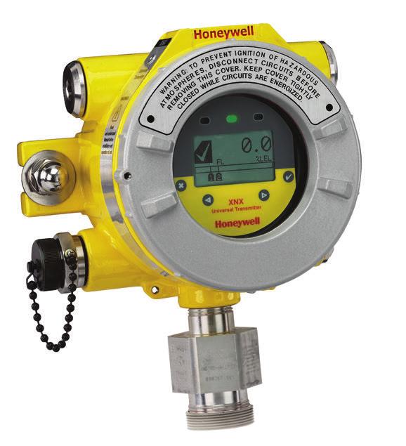
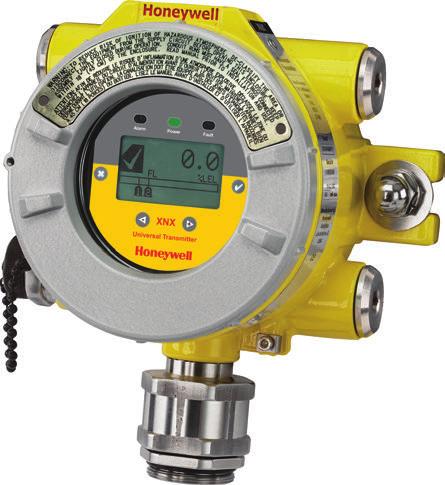
XNX Universal Transmitter
 XNX Universal Transmitter A universal transmitter for toxic, oxygen and combustible gas detection compatible with all Honeywell gas sensing technologies XNX Universal Transmitter Universal Gas Sensing
Sensepoint. The Sensepoint range of flammable, toxic and oxygen gas detectors offer users a low cost solution to their gas monitoring needs.
 Sensepoint The Sensepoint range of flammable, toxic and oxygen gas detectors offer users a low cost solution to their gas monitoring needs. Sensepoint One-Stop Shop Flammable, toxic and oxygen versions
Zareba System Overview
 Zareba System Overview Examples of Gas Detection System Layouts Zareba Fixed Point Gas Detection Throughout the Building Services Industry, there are many different applications that require gas detection
Signalpoint. The Signalpoint range of flammable, toxic and Oxygen gas detectors offer users a low cost solution to their indoor gas monitoring needs
 Signalpoint The Signalpoint range of flammable, toxic and Oxygen gas detectors offer users a low cost solution to their indoor gas monitoring needs Signalpoint One-Stop Shop Flammable, toxic and Oxygen
Measurement of Safety Integrity of E/E/PES according to IEC61508
 Measurement of Safety Integrity of E/E/PES according to IEC61508 Mr. Chen Zhenkang TUV Rheinland Singapore 18. May. 2018 Singapore World Metrology Day 2018 1 Agenda 1. TÜV Rheinland: a Certification Body
Searchpoint Optima Plus
 Searchpoint Optima Plus Advanced infrared point gas detector Searchpoint Optima Plus Why Infrared? Failsafe operation Fast speed of response Reduced routine maintenance Immune to catalytic poisons Long
Zareba Unipoint controller
 Zareba Unipoint controller The Zareba Unipoint, a simple DIN rail mounted controller Unipoint DIN controller Typical Applications Small and medium integrated systems ustom control cabinets and panels Unmanned
FMEDA Report. Failure Modes, Effects and Diagnostic Analysis. KFD0-CS-Ex*.54* and KFD0-CS-Ex*.56* Project: X7300
 Failure Modes, Effects and Diagnostic Analysis Device Designation: KFD0-CS-Ex*.54* and KFD0-CS-Ex*.56* Project: X7300 Pepperl+Fuchs GmbH Mannheim Germany Mannheim norm sheet 1 of 16 Released EDM checkout
Technical Summary. Searchpoint Optima Plus Specification. Output ma sink or source, (Default current source) 0-4 ma (Default 4 ma)
 0-4 ma (Default 4 ma)") Technical Summary Searchpoint Optima Plus Specification Output Measuring range Inhibit Warning Fault Over range 4-20 ma sink or source, (Default current source) 1-3 ma (Default 2 ma) 0-4 ma (Default 4
Technical Summary Searchpoint Optima Plus Specification Output Measuring range Inhibit Warning Fault Over range 4-20 ma sink or source, (Default current source) 1-3 ma (Default 2 ma) 0-4 ma (Default 4
Technical Manual Table of Contents Safety Information Introduction Installation and Operation
 XNX Universal Transmitter Technical Manual Table of Contents Safety Information Introduction Installation and Operation Calibration Maintenance Warnings/Faults Specifications Control Drawings HART Protocol
Metro Gas Detector. The Metro addressable gas detector enables remote monitoring of flammable and toxic gas hazards
 Metro Gas Detector The Metro addressable gas detector enables remote monitoring of flammable and toxic gas hazards Metro Gas Detector One-Stop Shop Flammable and toxic gas monitors available Methane, LNG
Failure Modes, Effects and Diagnostic Analysis
 Failure Modes, Effects and Diagnostic Analysis Project: Detcon FP-700 Combustible Gas Sensor Customer: Detcon The Woodlands, TX USA Contract No.: DC 06/08-04 Report No.: DC 06/08-04 R001 Version V1, Revision
EC FX NH3 SECONDARY HEADLINE. A new and improved approach to ammonia gas detection
 EC FX NH3 SECONDARY HEADLINE A new and improved approach to ammonia gas detection EC FX NH3 Sensor & Transmitter Introducing a better, tougher, longer-lasting sensor for industrial refrigeration Three
Training Presentation XNX
 Training Presentation XNX Premium Gas Detection Wide range of markets and applications including: - Refineries and chemical plants, onshore oil and gas terminals, production platforms, exploration and
SIL Safety Guide Series MS Single-Acting Spring-Return Hydraulic Linear Actuators
 SIL Safety Guide Series MS Single-Acting Spring-Return Hydraulic Linear Actuators Rev 0, November 17 2015 Page 1 of 9 Table of Contents 1 INTRODUCTION 3 1.1 Terms and abbreviations 3 1.2 Acronyms 4 1.3
SAFETY MANUAL. IR5000 Open Path Hydrocarbon Gas Monitoring System
 SAFETY MANUAL Open Path Hydrocarbon Gas Monitoring System The information and technical data disclosed in this document may be used and disseminated only for the purposes and to the extent specifically
Failure Modes, Effects and Diagnostic Analysis
 Failure Modes, Effects and Diagnostic Analysis Project: Oldham OLCT 200 Transmitter Company: Industrial Scientific Corporation Oakdale, PA USA Contract Number: Q11/05-009 Report No.: IS 10/10-010 R001
Searchpoint Optima Plus
 Searchpoint Optima Plus Advanced infrared point gas detector Searchpoint Optima Plus Why Infrared? Failsafe operation Fast speed of response Reduced routine maintenance Immune to catalytic poisons Long
SAFETY CERTIFIED MODEL FP-700 COMBUSTIBLE GAS DETECTOR
 SAFETY MANUAL SIL 2 Certified Model FP-700 Combustible Hydrocarbon Gas Sensor Version 2.0 1 SAFETY CERTIFIED MODEL FP-700 COMBUSTIBLE GAS DETECTOR This manual addresses the specific requirements and recommendations
Operating Instructions
 1. Safety Warnings and Information 1 Safety Warnings and Information WARNINGS 1. Installation must be in accordance with the recognized standards of the appropriate authority in the country concerned.
Sensepoint XCD RTD. Remotely monitor toxic gases in Class 1, Div 2 areas while reducing the maintenance, training and overall cost of gas monitoring
 Remotely monitor toxic gases in Class 1, Div 2 areas while reducing the maintenance, training and overall cost of gas monitoring Reduce Cost of Ownership Over Life of the Product Cut stocking and procurement
United Electric Controls One Series Safety Transmitter Safety Manual
 United Electric Controls One Series Safety Transmitter Safety Manual OneST-SM-02 1 INTRODUCTION This Safety Manual provides information necessary to design, install, verify and maintain a Safety Instrumented
Touchpoint Plus. A whole new control experience
 Touchpoint Plus A whole new control experience Touchpoint Plus Delivering reliable control Honeywell reliability from the most trusted experts in gas detection Built-in battery backup for constant uptime
User s Manual. YTA110, YTA310, YTA320, and YTA710 Temperature Transmitters. Manual Change No
 User s Manual YTA110, YTA310, YTA320, and YTA710 Temperature Transmitters Manual Change No. 16-045 Please use this manual change for the manuals listed below. 1. Applicable manuals, revised item, revised
Gas Detection. ConneXt Loneworker Real-time visibility on the safety, location and productivity of your isolated workers
 Gas Detection ConneXt Loneworker Real-time visibility on the safety, location and productivity of your isolated workers No matter how remote their location, lone workers are only a click away A mobile
Series 3000 XPIS. 2-wire loop powered toxic and Oxygen gas detector for use in potentially explosive atmospheres
 Series 3000 XPIS -wire loop powered toxic and Oxygen gas detector for use in potentially explosive atmospheres Series 3000 XPIS Reliable detection Proven electrochemical sensing technology Uses Surecell
Touchpoint Plus. A whole new control experience
 Touchpoint Plus A whole new control experience Touchpoint Plus Delivering reliable control Honeywell reliability from the most trusted experts in gas detection Built-in battery backup for constant uptime
SPM Flex Chemcassette Tape-Based Gas Detector
 Chemcassette Tape-Based Improving safety and productivity with the most flexible, user-friendly tape-based gas detector for low-level toxics feel more confident than ever about your plant s safety and
SAFETY MANUAL. Intelligent Sensors for H 2 S Gas Applications
 SAFETY MANUAL Intelligent Sensors for H 2 S Gas Applications The information and technical data disclosed in this document may be used and disseminated only for the purposes and to the extent specifically
SAFETY MANUAL. Electrochemical Gas Detector GT3000 Series Includes Transmitter (GTX) with H 2 S or O 2 Sensor Module (GTS)
 with H 2 S or O 2 Sensor Module (GTS)") SAFETY MANUAL Electrochemical Gas Detector GT3000 Series Includes Transmitter (GTX) with H 2 S or O 2 Sensor Module (GTS) Sensor Module (GTS) Transmitter (GTX) Detector (GT3000) SAFETY CERTIFIED GT3000
SAFETY MANUAL Electrochemical Gas Detector GT3000 Series Includes Transmitter (GTX) with H 2 S or O 2 Sensor Module (GTS) Sensor Module (GTS) Transmitter (GTX) Detector (GT3000) SAFETY CERTIFIED GT3000
Sieger Sensepoint. Easy to Use Factory set operation Simple to replace Minimal training required
 Sieger Sensepoint The Sensepoint range of flammable, toxic and oxygen gas detectors offer users a high quality, low cost solution to their industrial gas monitoring needs. Sieger Sensepoint Fit For Purpose
Zareba Metro Gas Detector
 Zareba Metro Gas Detector The Metro addressable gas detector enables remote monitoring of flammable and toxic gas hazards Metro Gas Detector One-Stop Shop Flammable and toxic gas monitors available Methane,
100 & 120 Series Pressure and Temperature Switches Safety Manual
 100 & 120 Series Pressure and Temperature Switches Safety Manual MECH-SM-01 1 INTRODUCTION This Safety Manual provides information necessary to design, install, verify and maintain a Safety Instrumented
System 57. An advanced World of intelligent gas detection system management
 An advanced World of intelligent gas detection system management A World of control technology High precision, intelligent control Master / voted alarm options High packing density Flexible I/O configuration
System 57. An advanced world of intelligent gas detection system management
 An advanced world of intelligent gas detection system management A world of control technology High precision, intelligent control Master/voted alarm options High packing density Flexible I/O configuration
STT850 and STT750 SmartLine Temperature Transmitter HART Communications Options Safety Manual 34-TT Revision 4 September 2017
 STT850 and STT750 SmartLine Temperature Transmitter HART Communications Options Safety Manual 34-TT-25-05 Revision 4 September 2017 Honeywell Process Solutions Copyrights, Notices and Trademarks Copyright
FUNCTIONAL SAFETY MANUAL
 f u n c t i o n a l S a f e t y M a n u a l FUNCTIONAL SAFETY MANUAL Gassonic Surveyor and Gassonic Observer Ultrasonic Gas Leak Detectors The information and technical data disclosed in this document
Technical Manual. LeakFilm 5. 5 Channel Conductive Liquid Leak Detection Controller
 Technical Manual LeakFilm 5 5 Channel Conductive Liquid Leak Detection Controller 1. Safety Ensure that this Operating Manual is read and understood BEFORE installing / operating / maintaining the equipment.
Safety Temperature Limiter STL 50 Certified to DIN EN (replaces DIN 3440)
") Safety Temperature Limiter STL 50 Certified to DIN EN 14597 (replaces DIN 3440) Features M For use as: STB Protection - temperature limiter ASTB Exhaust gas - protection - temperature limiter STW Protection
Safety Temperature Limiter STL 50 Certified to DIN EN 14597 (replaces DIN 3440) Features M For use as: STB Protection - temperature limiter ASTB Exhaust gas - protection - temperature limiter STW Protection
Technical Manual. LeakFilm Pro. Single Channel Conductive and Chemical Liquid Leak Detection Controller with Leak Location Detection
 Technical Manual LeakFilm Pro Single Channel Conductive and Chemical Liquid Leak Detection Controller with Leak Location Detection 1. Safety Ensure that this Operating Manual is read and understood BEFORE
Rosemount Functional Safety Manual. Manual Supplement , Rev AF March 2015
 Rosemount 2120 Functional Safety Manual Manual Supplement Manual Supplement Contents Contents 1Section 1: Introduction 1.1 Scope and purpose of the safety manual.................................. 1 1.2
White Paper. Critical Considerations for Monitoring Low Levels of Hydrogen Sulfide. by Jacob Spector and Kirk Johnson
 White Paper Critical Considerations for Monitoring Low Levels by Jacob Spector and Kirk Johnson 2015 Honeywell International, Inc. A New Threshold of Safety Critical Considerations When it comes to gas
XNX Universal Transmitter
 XNX Universal Transmitter A universal transmitter compatible with all Honeywell Analytics gas sensor technologies XNX Universal Transmitter Flexible Compatible with all Honeywell Analytics gas sensors
Technical Manual for the Manual Alarm Call Point BG
 Technical Manual for the Manual Alarm Call Point BG Please note that every care has been taken to ensure the accuracy of our technical manual. We do not, however, accept responsibility for damage, loss
Digital EPIC 2 Safety manual
 Safety manual Before installation these instructions must be fully read and understood Table of contents Safety manual... 1 1. Introduction... 1 1.1 Terms and abbreviations... 2 1.2 Acronyms... 2 1.3 Product
Zareba Sensepoint Pro
 Zareba Sensepoint Pro Comprehensive monitoring of flammable, toxic and oxygen gas hazards in potentially explosive atmospheres Sensepoint Pro One-Stop Shop Flammable, toxic and oxygen versions available
Unipoint Controller. The Unipoint, a simple DIN rail mounted controller
 Unipoint ontroller The Unipoint, a simple DIN rail mounted controller Unipoint DIN ontroller Typical Applications Small and medium integrated systems ustom control cabinets and panels Unmanned equipment
Technical Report Proven In Use SITRANS P500
 Technical Report Proven In Use SITRANS P500, Industry Sector, Industry Automation Division, Sensors and Communication, PD PA PI R&D PM CRT Oestliche Rheinbrueckenstr. 50 76187 Karlsruhe, Germany Number:
FUNCTIONAL SAFETY CERTIFICATE. BG Break Glass Unit
 FUNCTIONAL SAFETY CERTIFICATE This is to certify that the BG Break Glass Unit manufactured by Eaton MEDC Ltd Unit B Sutton Parkway Oddicroft Lane Sutton-In-Ashfield NG17 5FB UK has been assessed by with
SAFETY MANUAL. PointWatch Eclipse Infrared Hydrocarbon Gas Detector Safety Certified Model PIRECL
 SAFETY MANUAL PointWatch Eclipse Infrared Hydrocarbon Gas Detector SIL 2 Certified Model PIRECL Safety Certified Model PIRECL PointWatch Eclipse IR Gas Detector This manual addresses the specific requirements
Safety in the process industry
 Products Solutions Services Safety in the process industry Simply reliable Table of contents Endress+Hauser: At home in the process safety Smart devices and concepts for hazardous areas Introduction to
SAFETY MANUAL. FL4000H and FL4000 Multi-Spectral Infrared Flame Detectors
 SAFETY MANUAL FL4000H and FL4000 Multi-Spectral Infrared Flame Detectors The information and technical data disclosed in this document may be used and disseminated only for the purposes and to the extent
Introduction. Additional information. Additional instructions for IEC compliant devices. Measurement made easy
 ABB MEASUREMENT & ANALYTICS SIL-SAFETY MANUAL TTH300, TTF300 Temperature transmitter Additional instructions for IEC 61508 compliant devices Measurement made easy TTH300 TTF300 Introduction TTH300, TTF300
430128A. B-Series Flow Meter SIL Safety Manual
 430128A B-Series Flow Meter SIL Safety Manual Copyrights and Trademarks Copyright 2016 Kurz Instruments, Inc. All rights reserved. No part of this publication may be reproduced or transmitted in any form
XNX Universal Transmitter. A universal transmitter compatible with all Honeywell Analytics gas sensor technologies DRAFT
 XNX Universal Transmitter A universal transmitter compatible with all Honeywell Analytics gas sensor technologies XNX Universal Transmitter Flexible Compatible with all Honeywell Analytics gas sensors
Proservo NMS5- / NMS7-
 Functional Safety Manual Proservo NMS5- / NMS7- Tank gauge for Liquid level measurement with 4 to 20mA Output or with Alarm Relay Contact Output Application Operating minimum (e.g. dry run protection),
Installation Guide and Operating Manual
 Installation Guide and Operating Manual Flame Detector with Pigtail Cable, Models FS7-2173-2RP, -2RPC, -2RPT15, -2RPK, -2RPC-K, and 2RPC-KZ Stand-alone, Leak-proof, Digital, Electro-optical Semiconductor
Failure Modes, Effects and Diagnostic Analysis
 Failure Modes, Effects and Diagnostic Analysis Project: Honeywell Temperature Transmitter STT650 with 4-20 ma Output Company: Honeywell International Inc. Field Products 512 Virginia Drive Fort Washington,
Proof Testing Level Instruments
 Proof Testing Level Instruments Partial proof testing of level instruments can save millions of dollars while maintaining required safety ratings By Bill Sholette, Level Product Business Manager Endress+Hauser
Fixed-Point Industrial Gas Detection
 Fixed-Point Industrial Gas Detection Protecting People, Property and Environment from Toxic and Flammable Gases A Complete Range of Fixed-Point and Portable Gas Detectors for Industry Oil & Gas Applications
Sieger Apex. Flexibility that meets your requirements
 Sieger Apex Flexibility that meets your requirements Sieger Apex Easy to Install Sensor can be remotely mounted up to 100m from the transmitter On board relays allow for local audible/ visual alarms Strong
Fixed-Point Industrial Gas Detection
 Fixed-Point Industrial Gas Detection Protecting People, Property and Environment from Hazardous Gases A Complete Range of Fixed-Point Gas Detectors And Sensing Technologies Honeywell Analytics Offers Enhanced
Honeywell Analytics. Order List BW Clip & IntelliDoX
 Honeywell Analytics Order List BW Clip & IntelliDoX BW Clip Single-Gas Detector H 2 S, CO, O 2, SO 2 The most user-friendly, reliable and cost effective way to ensure safety and compliance The BW Clip
Ordering Information. Ordering Information. Transmitter S3KUX S3KAX
 Ordering Information Ordering Information A complete assembly consists of two parts, a transmitter and sensor which must be ordered separately. Transmitter PN#: Two certified versions are available: -
Rosemount 2140:SIS Level Detector
 Rosemount 2140:SIS Level Detector Functional Safety Manual Manual Supplement Manual Supplement Contents Contents 1Section 1: Introduction 1.1 Scope and purpose of the safety manual..................................
MX43. Analog and digital controller. 4 or 8 lines / 16 to 32 detectors max. Highly versatile controller. SIL1 reliability. Gas Detection Control Panel
 Gas Detection Control Panel MX Analog and digital controller or 8 lines / 6 to s max Highly versatile controller SIL reliability Fixed The Fixed Gas Gas Detection Detection Experts People www.oldhamgas.com
Certification Report of the ST 3000 Pressure Transmitter with HART 6
 Certification Report of the ST 3000 Pressure Transmitter with HART 6 Revision No.: 2.4 Date: Report Number: 2010-Mar-18 SAS-190/2006T Product: ST 3000 Pressure Transmitter with HART 6 Customer: Order Number:
Mechanics issn Transport issue 1, 2009 Communications article 0342
 Mechanics issn 1312-3823 Transport issue 1, 2009 Communications article 0342 Academic journal FUNCTIONAL SAFETY ASSESSMENT OF LED BASED SIGNAL LAMP http://www.mtc-aj.com Jan Famfulík, Radek Krzyžanek jan.famfulik@vsb.cz,
AreaRAE Pro Wireless, transportable area monitor Remote visibility on more threats than ever for an enhanced level of real-time situational
 AreaRAE Pro Wireless, transportable area monitor Remote visibility on more threats than ever for an enhanced level of real-time situational awareness. Superior wireless, transportable multi threat area
SAFETY MANUAL. Multispectrum IR Flame Detector X3301
 SAFETY MANUAL Multispectrum IR Flame Detector X3301 SAFETY-CERTIFIED MODEL X3301 MULTISPECTRUM INFRARED DETECTOR This manual addresses the specific requirements and recommendations applicable to the proper
Safety Integrity Verification and Validation of a High Integrity Pressure Protection System to IEC 61511
 TÜV Rheinland International Symposium in China Functional Safety in Industrial Applications October 18 19, 2011 in Shanghai China Safety Integrity Verification and Validation of a High Integrity Pressure
Certification Report of the ST3000 Pressure Transmitter
 Certification Report of the ST3000 Pressure Transmitter Revision No.: 1.0 Date: Report Number: Product: Customer: Order Number: Authority: Responsible: 2006-Dec-12 SAS-128/2006T ST3000 Pressure Transmitter
User Guide. MeshGuard Gamma
 User Guide MeshGuard Gamma Copyright 2013 Honeywell Analytics Contents 1 Product Kits... 6 1.1 Standard Kit... 6 1.2 Optional Accessories... 6 2 General Information... 6 3 Physical Description... 8 3.1
Failure Modes, Effects and Diagnostic Analysis
 Failure Modes, Effects and Diagnostic Analysis Project: Phoenix Type 85UVF/IRF Flame Scanner Company: FIREYE Derry, New Hampshire USA Contract Number: Q08/04-57 Report No.: FIR 08/04-57 R001 Version V2,
Failure Modes, Effects and Diagnostic Analysis
 Failure Modes, Effects and Diagnostic Analysis Project: Fireye Flame Sensor Module CE Flameswitch, model MBCE-110/230FR Company: Fireye Derry, NH USA Contract Number: Q09/10-26 Report No.: FIR 09/10-26
Failure Modes, Effects and Diagnostic Analysis. PR electronics A/S Rønde Denmark
 Failure Modes, Effects and Diagnostic Analysis Project: 9203 Solenoid / Alarm Driver Customer: PR electronics A/S Rønde Denmark Contract No.: PR electronics 06/03-19 Report No.: PR electronics 06/03-19
Operating Instructions
 Operating Instructions Unipoint Flammable and Toxic Gas Detection Controller 1 Safety Ensure that this manual is read and understood BEFORE installing / operating / maintaining the equipment. WARNINGS
Quick Start Guide. XNX Universal Transmitter
 Quick Start Guide XNX Universal Transmitter Table of Contents 1 Introduction...5 2 Warnings...6 3 Mounting and Location of Detectors...8 3.1 Mounting the XNX Universal Transmitter...8 4 Wiring the XNX
Searchline Excel. The Searchline Excel is the World s best selling infrared open path gas detector
 Searchline Excel The Searchline Excel is the World s best selling infrared open path gas detector Searchline Excel Applications include: Offshore platforms & vessels (FPSO s) Downstream chemical processing
MeshGuard and MeshGuard Gamma
 and RAE Systems by Honeywell Battery-Powered Wireless Gas Detector and Radiation Detector Battery-Powered Wireless Gas Detector Key Features Self-forming wireless network; units come online automatically