Use of the application program
|
|
|
- Bartholomew Hancock
- 5 years ago
- Views:
Transcription
1 Contents overview Use of the application program Use of the application program 1 1. Functional description 2 Switching on / off 2 Dimming brighter / darker 2 Dimming value (8 bit) 3 Status Switching (1 bit) 3 Status dimming value (8 bit) 3 Minimum dimming value 3 Maximum dimming value 3 Night mode (time-limited lighting for cleaning) 3 Warning before switch-off 3 Protection against over-load / short-circuit 3 Protection against over-temperature 3 Immunity to ripple control signals and electrical grid frequency fluctuations 4 Behavior on bus voltage failure / recovery 4 Building site function 4 Behavior on unloading the application program 4 Resetting the device to ex-factory settings 4 2. Communication objects 4 3. Functions (Objects, s) 5 Operating mode: Normal Mode 5 Operating mode: 1-level time switch mode 9 Operating mode: 2-level time switch mode 13 Operating mode: Flashing 17 Night mode 19 Locking 20 Status messaging 21 Switching cycles counter 23 Operating hours counter 24 Scene control Addition Behavior on bus voltage recovery depending on the operation mode Behavior on dimming via object Switching Graphic representation of starting position at different parameterisation 29 Product family: Product type: Manufacturer: Name: Order no: Name: Order no.: Product family: Product type: Manufacturer: Name: Order no.: Lighting Dimmer Siemens Universal dimmer, 1 x 250VA, AC 230V, with mounting bracket UP 525/03 5WG AB03 Universal dimmer, 1 x 250VA, AC 230V, without mounting bracket UP 525/13 5WG AB13 Room controller Lighting Siemens Universal dimmer (module), 1 x 250VA, AC 230V RS 525/23 5WG AB23 Siemens AG 982C01, 32 pages Technical manual Control Products and Systems Siemens AG 2012 Update: P. O. Box , D Regensburg Subject to change without further notice /1
. The device is installed in a flushmount wall box (60 mm;, depth 60 mm).")
2 1. Functional description The application program 07 B0 A1 Universal dimmer 982C01 can be used for the KNX devices listed above. These devices are briefly described in the next sections. The UP 525/03 Universal Dimmer with mounting frame is a KNX device with one dimmer output and a Bus Transceiver Interface (BTI). The device is installed in a flushmount wall box (60 mm;, depth 60 mm). The bus is connected via a bus terminal block. The actuator electronics are supplied via the bus voltage. DELTA bus wall switches or other application units (bus device) with BTI interface are plugged onto the BTI interface of the actuator. Any bus device, which can be slipped onto a bus coupling unit (BTM) UP 117, may be slipped onto this actuator. Dependent on the selected operating mode, objects for the functions switching, dimming brighter / darker and dimming value are available for the actuator output. Furthermore, if required, time-limited switching instead of permanent switching on can be enabled for each channel via an optional "Night mode" object (e.g. for lighting while cleaning), if need be with a warning before switching off by multiple switching the output on and off (flashing). Dependent on the configuration, additional objects are available for the output channel for the functions locking and status request. The following schema shows the named features in a logical overview. The UP 525/13 Universal Dimmer is a KNX device with one dimmer output. The device is installed in a flushmount wall box (60 mm Ø, depth 60 mm) or an installation box. The bus is connected via a bus terminal block. The actuator electronics are supplied via the bus voltage. The RS 525/23 Universal Dimmer is a KNX device with one dimmer output. The device is installed in an AP 118 Control Module Box or an AP 641 Room Control Box. The bus is connected via a bus terminal block. The actuator electronics are supplied via the bus voltage. These devices share the following features. The device can switch and dim resistive loads (e.g. incandescent lamps, high voltage halogen lamps), capacitive loads (e.g. low voltage halogen lamps with intermediate electronic transformers), or inductive loads (e.g. low voltage halogen lamps with intermediate conventional transformers). The actuator output may be set to one of the following operating modes: - Normal mode - 1-level time switch mode - 2-level time switch mode - Flashing Schematic design of a dimming actuator channel The application program includes optional a switching cycle and operating hours count with threshold monitoring for each output and an integrated 8-bit scene control, in which each output can be incorporated into up to 8 scenes. Switching on / off When a switching ON telegram is received, a parameter determines if the output channel is set to a preset dimming value, the dimming value on switching off or the last received dimming value. Switching OFF telegrams always result in switching the channel off. A parameter determines whether the output channel jumps to the preset switching on value respectively to the off value 0% or in what time it will be dimmed to the relevant value. Dimming brighter / darker The dimming time from 0% to 100% is set via a parameter. On receiving a start dimming command the actuator channel changes the brightness in the desired direction with the speed configured for dimming brighter/darker. If a stop command is received before the dimming action is completed, then dimming is stopped and the dimming value reached is maintained. Another parameter determines if the output can be switched on or off via dimming brighter / darker. Technical manual 982C01, 32 pages Siemens AG Update: Siemens AG 2012 Control Products and Systems /2
3 Dimming value (8 bit) Via the object A, Dimming value the channel output can be set to the received dimming value. It is configurable, whether the channel output jumps to the dimming value respectively in what time it will be dimmed to the relevant value. Another parameter determines if and under which conditions the output can be switched on or off via dimming value. Status Switching (1 bit) A parameter in the parameter window Functions, Objects determines if an object is available for the channel to read the current switching status of the channel and/or automatically send the status on change of value. Status dimming value (8 bit) A parameter in the parameter window Functions, Objects determines if an object is available for the channel to read the current dimming value of the channel and/or automatically send the dimming value on change of value. To limit the number of telegrams generated by dimming brighter/darker, the period between two dimming value status telegrams can be set via the parameter Delay status objects. Minimum dimming value A minimum dimming value can be configured. When dimming darker the channel can only be dimmed to the configured minimum value. Further dimming darker only results in turning the channel off if this is enabled via the configuration. If a dimming value lower than the minimum dimming value is received, the channel is only dimmed darker to the minimum dimming value. If the value 0 is received, the lighting is turned off, if this is enabled by the configuration. Maximum dimming value The configurable maximum dimming value for the channel can be used to limit the dimming range, The maximum dimming value cannot be exceeded by dimming brighter or by a received dimming value that is higher than the maximum value. Night mode (time-limited lighting for cleaning) Night mode can be enabled respectively disabled via an optionally selectable object (1 bit). If night mode is enabled for the channel then the channel can only be switched on for a limited time (time-limited lighting for cleaning). If night mode is enabled while the channel is on, then the dimming value of the channel is set to the maximum dimming value. If night mode is disabled while the channel is on, then the dimming value of the channel is left unchanged. The timer period for night mode is configured via a parameter. Warning before switch-off The parameter with the same name in the parameter window Functions, Objects determines whether the channel, when operating in night mode or 1-level time switch mode, shall signal an imminent automatic switching off about 30 seconds before timeout of the configured on period by reducing the brightness (dimming to 50% of the current value). This is to warn the room user and allow him to operate the light switch and thus extend the on period by the configured value before the lighting is turned off and leaves him in the dark. 8-bit scene control The parameter with the same name in the parameter window Functions, Objects determines whether the 8- bit scene control in the actuator is enabled for the channel. If it is enabled, a communication object 8-bit scene and a parameter window 8-bit scenes are added. Via the parameter window 8-bit scenes the channel can be incorporated individually in up to 8 scenes. Protection against over-load / short-circuit After about 5 seconds in an over-load condition the universal dimmer turns itself off permanently. At the earliest 2 minutes after an over-load or short-circuit tripping the dimmer may be turned on again. First send an off or a dimming value =0 command to turn the device off and then turn it on again by sending an on or a dimming value > 0 command. In a short-circuit condition the dimmer turns the load off for 3 seconds and automatically tries to switch the output on to the currently set dimming value once within 1 minute. If the short-circuit condition still persists the output is turned off permanently. Turn the output on again by following the instructions for a permanently turned off output in an over-load condition. Protection against over-temperature In case the maximum permissible temperature is exceeded the dimmer dims down to the minimal dimming value. If after 2 minutes the dimmer has cooled down sufficiently, it automatically dims back to the currently set dimming value. If after 2 minutes the maximum permissible over-temperature is still exceeded, the output is turned off permanently. Turn the output on again by following the instructions for a permanently turned off output in an over-load condition. Siemens AG 982C01, 32 Seiten Technik-Handbuch Infrastructure & Cities Sector, Building Technologies Control Products and Systems Siemens AG 2012 Update: Subject to change without further notice /3
4 Immunity to ripple control signals and electrical grid frequency fluctuations In the ex-factory settings the influence of ripple control signals is compensated to reduce flickering of the lamp. This measure increases the influence of electrical grid frequency fluctuations on the brightness of the lamp. A mostly undisturbed operation for an electrical system without a synchronous connection to the electrical grid can be achieved when the ripple control compensation is disabled via the associated parameter. The dimmer becomes less sensible to frequency fluctuations in the electrical system. Yet, ripple control signals will lead to an increased flickering of the load. Behavior on bus voltage failure / recovery On bus voltage failure the current switching status and dimming values are saved for restoration on bus voltage recovery. On bus voltage recovery the configured actions are executed and, if applicable, new status values are reported. Building site function The building site function provided ex-factory enables switching the building site lighting on and off via bus wall switches and actuators, even if these devices have not yet been commissioned with ETS. Behavior on unloading the application program When the application program is unloaded with ETS the device does not function. Resetting the device to ex-factory settings When the programming button is pressed for more than 20 seconds the device is reset to the ex-factory settings. All configuration settings are lost. The building site function is re-activated. 2. Communication objects Maximum number of group addresses: 120 Maximum number of assignments: 120 Note The number and names of communication objects visible can vary depending on the parameter settings. The application program already has been loaded in the factory. The device is configured and commissioned with Engineering Tool Software (ETS) version ETS v3.0f or higher. With the ETS (Engineering Tool Software) the specific parameters and addresses are assigned appropriately, and downloaded into the device. The following list shows all objects of the device. Which objects are visible and linkable to group addresses is defined via the functions assigned to the inputs. The objects and associated parameter settings are described with the functions. Nr. Object name Function Number of bits Flags 1 A, 8-bit scene recall / safe 1 byte CW 2 A, Locking On / Off 1 bit CW 3 A, Night mode On / Off 1 bit CW 4 A, Switching On / Off 1 bit CW 5 A, Dimming brighter / darker 4 bit CW 6 A, Dimming value 8-bit value 1 byte CW 8 A, Status switching On / Off 1 bit CRT 9 A, Status dimming value 8-bit value 1 byte CRT 10 A, Switching cycle counter 4-byte value 4 byte CR 11 A, Switching cycle threshold 4-byte value 4 byte CRW 12 A, Switching cycle threshold 1 = Yes / 0 = No 1 bit CRT overrun 13 A, Operating hours counter 4-byte value 4 byte CR 14 A, Operating hours threshold 4-byte value 4 byte CRW 15 A, Operating hours threshold overrun 1 = Yes / 0 = No 1 bit CRT Technical manual 982C01, 32 pages Siemens AG Update: Siemens AG 2012 Control Products and Systems /4

5 3. Functions (Objects, s) The actuator output can be configured individually with the following partial functions: Operating mode Normal mode Operating mode 1-level time switch mode Operating mode 2-level time switch mode Operating mode Flashing Night mode Locking Status messaging Number of switching cycles with or without threshold monitoring Number of operating hours with or without threshold monitoring 8-bit scene control Operating mode: Normal Mode In the operating mode Normal mode an additional night mode object can be added. When night mode is set via the night mode object then the behavior of the channel is similar to the 1-level time switch mode. The on period can be retriggered via the objects scene, switching, dimming brighter/darker or dimming value. When the on period has expired then the channel is turned off or, in case the warning before turning off is enabled, the dimming value is set to 50% of the last dimming value. If this value is below the minimum dimming value then the minimum dimming value is assumed. When the night mode object value is set to OFF (=0) then the timer mode is disabled. The following sections describe the functions, which can be configured for each channel, including the associated objects and parameter settings. Note The number and names of the parameter windows in the ETS menues may vary as they are controlled via parameter settings. Another parameter window may appear if due to dynamically added parameters the space in the first parameter window is exhausted. Objects Obj Object name Function Type Flag 4 A, Switching On / Off 1 bit CW Via this object the telegrams are received to switch the load connected to the respective channel on or off. 5 A, Dimming brighter / darker 4 bit CW Via this object the dimming telegrams for the relevant channel are received. 6 A, Dimming value 8-bit value 1 byte CW Via this object telegrams with a dimming value for the channel are received. If the received dimming value is below the minimum dimming value the behavior of the channel is determined by the parameter switching via dimming value. The dimming time for dimming to the dimming value depends on the parameter dimming time for setting dimming value from 0% to 100%. Siemens AG 982C01, 32 Seiten Technik-Handbuch Infrastructure & Cities Sector, Building Technologies Control Products and Systems Siemens AG 2012 Update: Subject to change without further notice /5

6 A Functions, Objects This parameter window offers selection of the base function (normal mode, 1-level timer mode, 2-level timer mode, flashing) and of further functions of this actuator output channel. This includes, -whether an 8-bit scene control shall be added, -whether a night mode object shall be added for this output channel, - whether the switching cycles of this output channel shall be counted with or without an upper threshold, - whether the operating hours for this output channel shall be counted with or without an upper threshold. - whether a status object for switching or dimming value shall be added for this output channel, - whether a locking object shall be added for this output channel, - how the output channel shall behave on bus voltage failure and bus voltage recovery. The parameter Operating mode is set to Normal mode. Operating mode Normal mode 1-level time switch mode 2-level time switch mode Flashing This parameter sets whether the channel is to work as a "normal" dimming channel or in 1-level timer mode, which can be switched on only via a switching, dimming, dimming value or scene recall command and is switched off automatically after the end of the configured on-time or whether it is to work in 2-level timer mode or whether it is to "flash". A 2-level timer mode is to be set for corridor and stairwell lighting if complete switching off of the lighting after the ontime 1 has elapsed is to be avoided. A 2-level timer mode is also set for control of colored lighting effects. If "1-level timer mode" is selected, then the parameter "ON period 1 (in minutes)" is also displayed. If a switching, dimming, dimming value or scene recall command is received again while 1- level timer mode and on period 1 are running, then the timer is reset to its initial value and the on-time extended accordingly. After the configured on period has expired, the output channel, if the warning function is enabled (via the parameter warning before switching off ), is dimmed to 50% of the current value. This is to warn the room user and allow him to operate the light switch and thus extend the on period by the configured value before the lighting is turned off. If 50% of the current dimming value are below the minimum dimming value then the minimum dimming value is assumed. If "2-level timer mode" is selected, then the three parameters "ON period 1 (in minutes), "ON period 2 (in minutes)" and "Dimming value during ON period 2 (in percent)" are also shown. Whereas dimming reverts to 0% at the end of a 1-level timer mode, in 2-level timer mode it will be dimmed at the end of the first ON period to the "dimming value during ON period 2" which can be above or below the previous dimming value. Dimming reverts to 0% at the end of the 2-level timer mode. There is no warning before switching off In 2-level time switch mode. If "Flashing" is selected, then the two parameters "ON period Flashing (1 255 seconds)" and "OFF period Flashing (1 255 seconds)" are shown additionally, which define the blinking behavior. The switching object of the channel is used to start and end blinking. The dimming value during the on period is determined by the parameter maximum dimming value. The objects scene, dimming, and dimming value and the associated parameters are not visible in the operating mode flashing Behavior on bus voltage switch off; failure switch on to maximum dimming value; no change This parameter determines the behavior of the actuator channel (dimmer output) on bus voltage failure: no change = On bus voltage failure the dimming value of the channel does not change. switch on to maximum dimming value = On bus voltage failure the channel is switched on to the maximum dimming value. switch off = On bus voltage failure the channel is switched off. Behavior on bus voltage recovery switch off; switch on; switch on to dimming value on bus voltage recovery ; as before voltage failure On bus voltage failure the current switching states and dimming values of all channels are saved in non-volatile memory. This allows restoring the states at bus voltage failure on bus voltage recovery. This parameter determines the behavior of the actuator channel (dimmer output) on bus voltage recovery: switch off : On bus voltage recovery the channel is switched off permanently (off state, 0%). switch on : On bus voltage recovery the channel is switched on permanently (to the switching on value). Technical manual 982C01, 32 pages Siemens AG Update: Siemens AG 2012 Control Products and Systems /6

7 switch on to dimming value on bus voltage recovery : a new parameter dimming value on bus voltage recovery appears. The output is switched on to the value set by that parameter. no change = On bus voltage failure the dimming value of the channel does not change. as before voltage failure : The state at bus voltage failure is restored. Value on bus voltage recovery [0 100%] 100 (0 100) This parameter is visible, if the parameter behavior on bus voltage recovery is set to switch on to dimming value on bus voltage recover. This parameter determines the dimming value to be set on bus voltage recovery. This value is limited by the minimum and maximum dimming values. The other parameters are covered in the sections Night mode Locking Status messaging Switching cycle counter Operating hours counter Scene control A, Dimming This parameter window is used to set the behavior of the corresponding actuator output channel in "Normal mode". Load adaptation: Dimmer Operating according to Automatic detection of load type; Leading edge principle; Trailing edge principle This parameter sets the type of load matching. With automatic load adaptation, the device checks the type of load when the mains voltage is switched on and decides whether to select leading or trailing edge control. If the load type cannot be unambiguously determined, the automatic load adaptation can be deactivated and the operating mode manually fixed by setting the mode to leading edge principle or trailing edge principle. Primarily, this is required for the operation of dimmable energy saving lamps. Note: With energy-saving lamps, we recommend in principle that you do not set this mode to "Automatic load adaptation", but to "leading edge control" or "trailing edge control" as recommended by the manufacturer of the lamp. Compensation ripple control No; Yes This parameter determines if ripple control signals detected by the device shall automatically be compensated. Not or falsely compensated ripple control signals on the mains power may cause flickering of the lamp. Minimum dimming value [1 50%] 1 (1 50) This parameter sets the minimum dimming value, which cannot be under-run when "dimming darker" (i.e. it can only be dimmed down to the minimum dimming value ). If the parameter "Switching off via dimming darker" is set to Yes, then a "Dimming darker" value below the minimum dimming value means that the channel will be switched off. If the parameter "Switching via dimming value" is set to Off if dimming value < min. dimming value, then a dimming value below the minimum dimming value means that the channel will be switched off. If the parameter "Switching via dimming value" is set to Switching On and switching Off possible, then a dimming value below the minimum dimming value means that the channel will be switched off. Maximum dimming value [10 100%] 100 (10 100) This parameter sets the maximum dimming value, which cannot be exceeded (i.e. in any case dimming is only possible to the maximum dimming value). When dimming brighter this is only possible up to the maximum dimming value. If a dimming value above the maximum dimming value is received then the output channel is only dimmed to the maximum dimming value. Dimming time for switching On/Off [ seconds] 0 ( ) This parameter determines if the configured ON value respectively the OFF value 0% are jumped to (dimming time = 0) or in what time it will be dimmed to the relevant value. If the channel is not switched off from 100% to 0% respectively switched on from 0% to 100% then the dimming time is proportionally adjusted to the difference of the old and new dimming values. Siemens AG 982C01, 32 Seiten Technik-Handbuch Infrastructure & Cities Sector, Building Technologies Control Products and Systems Siemens AG 2012 Update: Subject to change without further notice /7
8 Dimming time for dimming 5 darker / brighter from ( ) 0%-100% [ seconds] This parameter determines the time in which dimming is performed from 0% to 100% (or from 100% to 0%) with manual (relative) dimming. If the channel is not dimmed from 0% to 100% respectively from 100% to 0% then the dimming time is proportionally adjusted to the difference of the old and new dimming values. Depending on the difference the time for reaching the target value varies. Dimming time for setting dimming value from % [ seconds] 0 ( ) This parameter determines whether a new dimming value is to be jumped to (dimming time = 0) or in what time it will be dimmed from 0% to 100% (or from 100% to 0%). If the channel is not dimmed from 0% to 100% respectively from 100% to 0% then the dimming time is proportionally adjusted to the difference of the old and new dimming values. Depending on the difference the time for reaching the target value varies. Starting value Dimming value at switching off; switch on value according to parameter; last received dimming value This parameter defines to which value this channel is to be jumped or dimmed on receiving a telegram with an "ON" switching command. If the setting "dimming value at switching OFF" is selected, then it switches to the last dimming value before switching off. If the channel is switched off by a dimming value below the minimum dimming value or by a dimming darker below the minimum dimming value or by a limited on-time (timer mode or lighting for cleaning in night mode), then the lighting switches on again at that last dimming value in each case. The setting "dimming value at switching OFF" is beneficial in a child's room or bedroom, where pressing the switch briefly for the first time then switches to the dimming value at switching off and pressing the switch briefly a second time dims or jumps to the max. dimming value. The setting "last received dimming value" is, for example needed for constant brightness control, if the lighting is not to be switched off by dimming values sent by a constant brightness controller which are below the minimum and not to be switched on by a dimming value above it. The parameter "Switching via dimming value n" must also be set to "not possible" for this. Switch On value [1 100%] 100 (1 100) This parameter is only visible if the parameter Starting value is set to switch on value according to parameter. This parameter determines the dimming value to be dimmed to when an on switching command is received. Switching off via dimming darker No Yes If the channel is to be switched off in the switched on status by dimming to a value below the minimum dimming value, then this parameter must be set to "Yes". Switching on via dimming brighter No Yes If switching on is to be possible in the off state by receiving a relative dimming value "brighter", this parameter must be set to "Yes". In this case, the channel is always switched on first, jumped to the minimum dimming value and then dimmed brighter to the received relative dimming value using the configured dimming time for dimming brighter / darker. Switching via dimming value not possible; On if dimming value >= min. dimming value; Off if dimming value < min. dimming value; Switching On and switching Off possible; On if dimming value > 0% / Off if dimming value = 0% If switching on in the off state shall be possible by receiving a dimming value, which is the same as or greater than the minimum dimming value, then this parameter must be set to "ON if dimming value min. dimming value". The channel is then switched on and either jumped or dimmed to the dimming value with the configured dimming time for dimming value setting. If the received dimming value is below the minimum dimming value, then the channel remains off. Switching off via dimming value setting is impossible with this setting. If the channel is switched on and this parameter is set to "OFF if dimming value < min. dimming value", then receiving a telegram with a dimming value < the minimum dimming value leads to dimming (with the configured dimming time for dimming value setting) down to the minimum dimming value and then to switching off of the channel. Switching on with dimming value setting is impossible with this setting. If this parameter is set to "switching ON and switching OFF possible", then the channel is switched on if the received dimming value is the minimum dimming value and it is switched off if the received dimming value is < min. dimming value. If the parameter is set to "ON if dimming value > 0% / OFF if dimming value = 0%", then any dimming value > 0% switches the channel on. If the dimming value is below the min. dimming value, the channel is set to the min. dimming value. The channel is switched off only after receipt of a dimming value 0%. ON delay [0 600 seconds] 0 (0 600) This parameter sets the wanted ON delay time. A set ON delay acts only on the object "Switching". The default setting "0" means that ON commands are executed immediately. OFF delay [0 600 seconds] 0 (0 600) This parameter sets the wanted OFF delay time. A set OFF delay acts only on the object "Switching". The default setting "0" means that OFF commands are executed immediately. Technical manual 982C01, 32 pages Siemens AG Update: Siemens AG 2012 Control Products and Systems /8


9 Operating mode: 1-level time switch mode The on period can be triggered and retriggered via the objects scene, switching, dimming brighter/darker or dimming value. When the on period has expired then the channel is turned off or, in case the warning before turning off is enabled, the dimming value is set to 50% of the last dimming value. If this value is below the minimum dimming value then the minimum dimming value is assumed. A Functions, Objects Objects Obj Object name Function Type Flag 4 A, Switching On / Off 1 bit CW Via this object the telegrams are received to switch the load connected to the respective channel on or off. 5 A, Dimming brighter / darker 4 bit CW Via this object the dimming telegrams for the relevant channel are received. 6 A, dimming value 8-bit value 1 byte CW Via this object telegrams with a dimming value for the channel are received. If the received dimming value is below the minimum dimming value the behavior of the channel is determined by the parameter switching via dimming value. The dimming time for dimming to the dimming value depends on the parameter dimming time for setting dimming value from 0% to 100%. This parameter window offers selection of the base function (normal mode, 1-level timer mode, 2-level timer mode, flashing) and of further functions of this actuator output channel. This includes, -whether an 8-bit scene control shall be added, - whether the switching cycles of this output channel shall be counted with or without an upper threshold, - whether the operating hours for this output channel shall be counted with or without an upper threshold. - whether a status object for switching or dimming value shall be added for this output channel, - whether a locking object shall be added for this output channel, - how the output channel shall behave on bus voltage failure and bus voltage recovery. The parameter Operating mode is set to 1-level time switch mode. Operating mode Normal mode 1-level time switch mode 2-level time switch mode Flashing This parameter sets whether the channel is to work as a "normal" dimming channel or in 1-level timer mode, which can be switched on only via a switching, dimming, dimming value or scene recall command and is switched off automatically after the end of the configured on-time or whether it is to work in 2-level timer mode or whether it is to "flash". A 2-level timer mode is to be set for corridor and stairwell lighting if complete switching off of the lighting after the ontime 1 has elapsed is to be avoided. A 2-level timer mode is also set for control of colored lighting effects. If "1-level timer mode" is selected, then the parameter "ON period 1 (in minutes)" is also displayed. If a switching, dimming, dimming value or scene recall command is received again while 1-level timer mode and on period 1 are running, then the timer is reset to its initial value and the on-time extended accordingly. After the configured on period has expired, the output chan- Siemens AG 982C01, 32 Seiten Technik-Handbuch Infrastructure & Cities Sector, Building Technologies Control Products and Systems Siemens AG 2012 Update: Subject to change without further notice /9
10 nel, if the warning function is enabled (via the parameter warning before switching off ), is dimmed to 50% of the current value. This is to warn the room user and allow him to operate the light switch and thus extend the on period by the configured value before the lighting is turned off. If 50% of the current dimming value are below the minimum dimming value then the minimum dimming value is assumed. If "2-level timer mode" is selected, then the three parameters "ON period 1 (in minutes), "ON period 2 (in minutes)" and "Dimming value during ON period 2 (in percent)" are also shown. Whereas dimming reverts to 0% at the end of a 1-level timer mode, in 2-level timer mode it will be dimmed at the end of the first ON period to the "dimming value during ON period 2" which can be above or below the previous dimming value. Dimming reverts to 0% at the end of the 2-level timer mode. There is no warning before switching off In 2-level time switch mode. If "Flashing" is selected, then the two parameters "ON period Flashing (1 255 seconds)" and "OFF period Flashing (1 255 seconds)" are shown additionally, which define the blinking behavior. The switching object of the channel is used to start and end blinking. The dimming value during the on period is determined by the parameter maximum dimming value. The objects scene, dimming, and dimming value and the associated parameters are not visible in the operating mode flashing Warning before switching off 30 [0 255 seconds] (0 255) This parameter determines for a channel in night mode or in 1-level time switch mode, how long after the timer has expired an imminent switching off shall be signaled by reducing the brightness (50% of the current dimming value). When the room user operates the light switch then the lighting is turned on for the period configured for night mode or 1- level switch time mode. Behavior on bus voltage failure switch off; switch on to maximum dimming value; no change This parameter determines the behavior of the actuator channel (dimmer output) on bus voltage failure: no change = On bus voltage failure the dimming value of the channel does not change. switch on to maximum dimming value = On bus voltage failure the channel is switched on to the maximum dimming value. switch off = On bus voltage failure the channel is switched off. Behavior on bus voltage recovery switch off; switch on; switch on to dimming value on bus voltage recovery ; as before voltage failure On bus voltage failure the current switching states and dimming values of all channels are saved in non-volatile memory. This allows restoring the states at bus voltage failure on bus voltage recovery. This parameter determines the behavior of the actuator chan- nel (dimmer output) on bus voltage recovery: switch off : On bus voltage recovery the channel is switched off permanently (off state, 0%). switch on : On bus voltage recovery the channel is switched on permanently (to the switching on value). switch on to dimming value on bus voltage recovery : a new parameter dimming value on bus voltage recovery appears. The output is switched on to the value set by that parameter. no change = On bus voltage failure the dimming value of the channel does not change. as before voltage failure : The state at bus voltage failure is restored. Value on bus voltage recovery [0 100%] 100 (0 100) This parameter is visible, if the parameter behavior on bus voltage recovery is set to switch on to dimming value on bus voltage recover. This parameter determines the dimming value to be set on bus voltage recovery. This value is limited by the minimum and maximum dimming values. The other parameters are covered in the sections Night mode Locking Status messaging Switching cycle counter Operating hours counter Scene control A, Dimming This parameter window is used to set the behavior of the corresponding actuator output channel in "1-level time switch mode". Technical manual 982C01, 32 pages Siemens AG Update: Siemens AG 2012 Control Products and Systems /10
11 Load adaptation: Dimmer Operating according to Automatic detection of load type; Leading edge principle; Trailing edge principle This parameter sets the type of load matching. With automatic load adaptation, the device checks the type of load when the mains voltage is switched on and decides whether to select leading or trailing edge control. If the load type cannot be unambiguously determined, the automatic load adaptation can be deactivated and the operating mode manually fixed by setting the mode to leading edge principle or trailing edge principle. Primarily, this is required for the operation of dimmable energy saving lamps. Note: With energy-saving lamps, we recommend in principle that you do not set this mode to "Automatic load adaptation", but to "leading edge control" or "trailing edge control" as recommended by the manufacturer of the lamp. Compensation ripple control No; Yes This parameter determines if ripple control signals detected by the device shall automatically be compensated. Not or falsely compensated ripple control signals on the mains power may cause flickering of the lamp. Minimum dimming value [1 50%] 1 (1 50) This parameter sets the minimum dimming value, which cannot be under-run when "dimming darker" (i.e. it can only be dimmed down to the minimum dimming value ). If the parameter "Switching off via dimming darker" is set to Yes, then a "Dimming darker" value below the minimum dimming value means that the channel will be switched off. If the parameter "Switching via dimming value" is set to Off if dimming value < min. dimming value, then a dimming value below the minimum dimming value means that the channel will be switched off. If the parameter "Switching via dimming value" is set to Switching On and switching Off possible, then a dimming value below the minimum dimming value means that the channel will be switched off. Maximum dimming value [10 100%] 100 (10 100) This parameter sets the maximum dimming value, which cannot be exceeded (i.e. in any case dimming is only possible to the maximum dimming value). When dimming brighter this is only possible up to the maximum dimming value. If a dimming value above the maximum dimming value is received then the output channel is only dimmed to the maximum dimming value. Dimming time for switching On/Off [ seconds] 0 ( ) This parameter determines if the configured ON value respectively the OFF value 0% are jumped to (dimming time = 0) or in what time it will be dimmed to the relevant value. If the channel is not switched off from 100% to 0% respectively switched on from 0% to 100% then the dimming time is proportionally adjusted to the difference of the old and new dimming values. Dimming time for dimming darker / brighter from 0%-100% [ seconds] 5 ( ) This parameter determines the time in which dimming is performed from 0% to 100% (or from 100% to 0%) with manual (relative) dimming. If the channel is not dimmed from 0% to 100% respectively from 100% to 0% then the dimming time is proportionally adjusted to the difference of the old and new dimming values. Depending on the difference the time for reaching the target value varies. Dimming time for setting dimming value from % [ seconds] 0 ( ) This parameter determines whether a new dimming value is to be jumped to (dimming time = 0) or in what time it will be dimmed from 0% to 100% (or from 100% to 0%). If the channel is not dimmed from 0% to 100% respectively from 100% to 0% then the dimming time is proportionally adjusted to the difference of the old and new dimming values. Depending on the difference the time for reaching the target value varies. Starting value Dimming value at switching off; switch on value according to parameter; last received dimming value This parameter defines to which value this channel is to be jumped or dimmed on receiving a telegram with an "ON" switching command. If the setting "dimming value at switching OFF" is selected, then it switches to the last dimming value before switching off. If the channel is switched off by a dimming value below the minimum dimming value or by a dimming darker below the minimum dimming value or by a limited on-time (timer mode or lighting for cleaning in night mode), then the lighting switches on again at that last dimming value in each case. The setting "dimming value at switching OFF" is beneficial in a child's room or bedroom, where pressing the switch briefly for the first time then switches to the dimming value at switching off and pressing the switch briefly a second time dims or jumps to the max. dimming value. The setting "last received dimming value 1 or 2" is, for example needed for constant brightness control, if the lighting is not to be switched off by dimming values sent by a constant brightness controller which are below the minimum and not to be switched on by a dimming value above it. The parameter "Switching via dimming value n" must also be set to "not possible" for this. Switch On value [1 100%] 100 (1 100) This parameter is only visible if the parameter Starting value is set to switch on value according to parameter. This parameter determines the dimming value to be dimmed to when an on switching command is received. Siemens AG 982C01, 32 Seiten Technik-Handbuch Infrastructure & Cities Sector, Building Technologies Control Products and Systems Siemens AG 2012 Update: Subject to change without further notice /11
12 Switching off via dimming darker No Yes ON delay [0 600 seconds] 0 (0 600) If the channel is to be switched off in the switched on status by dimming to a value below the minimum dimming value, then this parameter must be set to "Yes". Switching on via dimming brighter No Yes If switching on is to be possible in the off state by receiving a relative dimming value "brighter", this parameter must be set to "Yes". In this case, the channel is always switched on first, jumped to the minimum dimming value 1 and then dimmed brighter to the received relative dimming value using the configured dimming time for dimming brighter / darker. Switching via dimming value not possible; On if dimming value >= min. dimming value; Off if dimming value < min. dimming value; Switching On and switching Off possible; On if dimming value > 0% / Off if dimming value = 0% If switching on in the off state shall be possible by receiving a dimming value, which is the same as or greater than the minimum dimming value, then this parameter must be set to "ON if dimming value min. dimming value". The channel is then switched on and either jumped or dimmed to the dimming value with the configured dimming time for dimming value setting. If the received dimming value is below the minimum dimming value, then the channel remains off. Switching off via dimming value setting is impossible with this setting. If the channel is switched on and this parameter is set to "OFF if dimming value < min. dimming value", then receiving a telegram with a dimming value < the minimum dimming value leads to dimming (with the configured dimming time for dimming value setting) down to the minimum dimming value 1 and then to switching off of the channel. Switching on with dimming value setting is impossible with this setting. If this parameter is set to "switching ON and switching OFF possible", then the channel is switched on if the received dimming value is the minimum dimming value 1 and it is switched off if the received dimming value is < min. dimming value 1. If the parameter is set to "ON if dimming value > 0% / OFF if dimming value = 0%", then any dimming value > 0% switches the channel on. If the dimming value is below the min. dimming value, the channel is set to the min. dimming value. The channel is switched off only after receipt of a dimming value 0%. ON period 1 15 [ minutes] ( ) This parameter is visible if the operating mode 1-level switch time mode or 2-level switch time mode is selected. This parameter determines the ON period respectively the ON period 1 in 2-level switch time mode. If during the on period a command is received via the objects scene, switching, dimming brighter/darker or dimming value, then that command is executed and the timer for the on period is retriggered. This parameter sets the wanted ON delay time. A set ON delay acts only on the object "Switching". The default setting "0" means that ON commands are executed immediately. OFF delay [0 600 seconds] 0 (0 600) This parameter sets the wanted OFF delay time. A set OFF delay acts only on the object "Switching". The default setting "0" means that OFF commands are executed immediately. Technical manual 982C01, 32 pages Siemens AG Update: Siemens AG 2012 Control Products and Systems /12


13 Operating mode: 2-level time switch mode The on period 1 can be triggered and retriggered via the objects scene, switching, dimming brighter/darker or dimming value. When the on period 1 has expired then the channel is dimmed to the dimming value for on period 2 in the time dimming time switching. There is no warning before switching off In 2-level time switch mode. When the timer is retriggered during on period 2 then the timer is reset into the on period 1. A Functions, Objects Objects Obj Object name Function Type Flag 4 A, Switching On / Off 1 bit CW Via this object the telegrams are received to switch the load connected to the respective channel on or off. 5 A, Dimming brighter / darker 4 bit CW Via this object the dimming telegrams for the relevant channel are received. 6 A, Dimming value 8-bit value 1 byte CW Via this object telegrams with a dimming value for the channel are received. If the received dimming value is below the minimum dimming value the behavior of the channel is determined by the parameter switching via dimming value. The dimming time for dimming to the dimming value depends on the parameter dimming time for setting dimming value from 0% to 100%. This parameter window offers selection of the base function (normal mode, 1-level timer mode, 2-level timer mode, flashing) and of further functions of this actuator output channel. This includes, -whether an 8-bit scene control shall be added, - whether the switching cycles of this output channel shall be counted with or without an upper threshold, - whether the operating hours for this output channel shall be counted with or without an upper threshold. - whether a status object for switching or dimming value shall be added for this output channel, - whether a locking object shall be added for this output channel, - how the output channel shall behave on bus voltage failure and bus voltage recovery. The parameter Operating mode is set to 2-level time switch mode. Operating mode Normal mode 1-level time switch mode 2-level time switch mode Flashing This parameter sets whether the channel is to work as a "normal" dimming channel or in 1-level timer mode, which can be switched on only via a switching, dimming, dimming value or scene recall command and is switched off automatically after the end of the configured on-time or whether it is to work in 2-level timer mode or whether it is to "flash". A 2-level timer mode is to be set for corridor and stairwell lighting if complete switching off of the lighting after the ontime 1 has elapsed is to be avoided. A 2-level timer mode is also set for control of colored lighting effects. If "1-level timer mode" is selected, then the parameter "ON period 1 (in minutes)" is also displayed. If a switching, dimming, dimming value or scene recall command is received again while 1- level timer mode and on period 1 are running, then the timer is reset to its initial value and the on-time extended accordingly. After the configured on period has expired, the output chan- Siemens AG 982C01, 32 Seiten Technik-Handbuch Infrastructure & Cities Sector, Building Technologies Control Products and Systems Siemens AG 2012 Update: Subject to change without further notice /13

14 nel, if the warning function is enabled (via the parameter warning before switching off ), is dimmed to 50% of the current value. This is to warn the room user and allow him to operate the light switch and thus extend the on period by the configured value before the lighting is turned off. If 50% of the current dimming value are below the minimum dimming value then the minimum dimming value is assumed. If "2-level timer mode" is selected, then the three parameters "ON period 1 (in minutes), "ON period 2 (in minutes)" and "Dimming value during ON period 2 (in percent)" are also shown. Whereas dimming reverts to 0% at the end of a 1-level timer mode, in 2-level timer mode it will be dimmed at the end of the first ON period to the "dimming value during ON period 2" which can be above or below the previous dimming value. Dimming reverts to 0% at the end of the 2-level timer mode. There is no warning before switching off In 2-level time switch mode. If "Flashing" is selected, then the two parameters "ON period Flashing (1 255 seconds)" and "OFF period Flashing (1 255 seconds)" are shown additionally, which define the blinking behavior. The switching object of the channel is used to start and end blinking. The dimming value during the on period is determined by the parameter maximum dimming value. The objects scene, dimming, and dimming value and the associated parameters are not visible in the operating mode flashing Behavior on bus voltage switch off; failure switch on to maximum dimming value; no change This parameter determines the behavior of the actuator channel (dimmer output) on bus voltage failure: no change = On bus voltage failure the dimming value of the channel does not change. switch on to maximum dimming value = On bus voltage failure the channel is switched on to the maximum dimming value. switch off = On bus voltage failure the channel is switched off. Behavior on bus voltage recovery switch off; switch on; switch on to dimming value on bus voltage recovery ; as before voltage failure On bus voltage failure the current switching states and dimming values of all channels are saved in non-volatile memory. This allows restoring the states at bus voltage failure on bus voltage recovery. This parameter determines the behavior of the actuator channel (dimmer output) on bus voltage recovery: switch off : On bus voltage recovery the channel is switched off permanently (off state, 0%). switch on : On bus voltage recovery the channel is switched on permanently (to the switching on value). switch on to dimming value on bus voltage recovery : a new parameter dimming value on bus voltage recovery appears. The output is switched on to the value set by that parameter. no change = On bus voltage failure the dimming value of the channel does not change. as before voltage failure : The state at bus voltage failure is restored. Value on bus voltage recovery [0 100%] 100 (0 100) This parameter is visible, if the parameter behavior on bus voltage recovery is set to switch on to dimming value on bus voltage recover. This parameter determines the dimming value to be set on bus voltage recovery. This value is limited by the minimum and maximum dimming values. The other parameters are covered in the sections Night mode Locking Status messaging Switching cycle counter Operating hours counter Scene control A, Dimming This parameter window is used to set the behavior of the corresponding actuator output channel in "2-level time switch mode". Technical manual 982C01, 32 pages Siemens AG Update: Siemens AG 2012 Control Products and Systems /14
15 Load adaptation: Dimmer Operating according to Automatic detection of load type; Leading edge principle; Trailing edge principle This parameter sets the type of load matching. With automatic load adaptation, the device checks the type of load when the mains voltage is switched on and decides whether to select leading or trailing edge control. If the load type cannot be unambiguously determined, the automatic load adaptation can be deactivated and the operating mode manually fixed by setting the mode to leading edge principle or trailing edge principle. Primarily, this is required for the operation of dimmable energy saving lamps. Note: With energy-saving lamps, we recommend in principle that you do not set this mode to "Automatic load adaptation", but to "leading edge control" or "trailing edge control" as recommended by the manufacturer of the lamp. Compensation ripple control No; Yes This parameter determines if ripple control signals detected by the device shall automatically be compensated. Not or falsely compensated ripple control signals on the mains power may cause flickering of the lamp. Minimum dimming value [1 50%] 1 (1 50) This parameter sets the minimum dimming value, which cannot be under-run when "dimming darker" (i.e. it can only be dimmed down to the minimum dimming value ). If the parameter "Switching off via dimming darker" is set to Yes, then a "Dimming darker" value below the minimum dimming value means that the channel will be switched off. If the parameter "Switching via dimming value" is set to Off if dimming value < min. dimming value, then a dimming value below the minimum dimming value means that the channel will be switched off. If the parameter "Switching via dimming value" is set to Switching On and switching Off possible, then a dimming value below the minimum dimming value means that the channel will be switched off. Maximum dimming value [10 100%] 100 (10 100) This parameter sets the maximum dimming value, which cannot be exceeded (i.e. in any case dimming is only possible to the maximum dimming value). When dimming brighter this is only possible up to the maximum dimming value. If a dimming value above the maximum dimming value is received then the output channel is only dimmed to the maximum dimming value. Dimming time for switching On/Off [ seconds] 0 ( ) This parameter determines if the configured ON value respectively the OFF value 0% are jumped to (dimming time = 0) or in what time it will be dimmed to the relevant value. If the channel is not switched off from 100% to 0% respectively switched on from 0% to 100% then the dimming time is proportionally adjusted to the difference of the old and new dimming values. Dimming time for dimming darker / brighter from 0%-100% [ seconds] 5 ( ) This parameter determines the time in which dimming is performed from 0% to 100% (or from 100% to 0%) with manual (relative) dimming. If the channel is not dimmed from 0% to 100% respectively from 100% to 0% then the dimming time is proportionally adjusted to the difference of the old and new dimming values. Depending on the difference the time for reaching the target value varies. Dimming time for setting dimming value from % [ seconds] 0 ( ) This parameter determines whether a new dimming value is to be jumped to (dimming time = 0) or in what time it will be dimmed from 0% to 100% (or from 100% to 0%). If the channel is not dimmed from 0% to 100% respectively from 100% to 0% then the dimming time is proportionally adjusted to the difference of the old and new dimming values. Depending on the difference the time for reaching the target value varies. Starting value Dimming value at switching off; switch on value according to parameter; last received dimming value This parameter defines to which value this channel is to be jumped or dimmed on receiving a telegram with an "ON" switching command. If the setting "dimming value at switching OFF" is selected, then it switches to the last dimming value before switching off. If the channel is switched off by a dimming value below the minimum dimming value or by a dimming darker below the minimum dimming value or by a limited on-time (timer mode or lighting for cleaning in night mode), then the lighting switches on again at that last dimming value in each case. The setting "dimming value at switching OFF" is beneficial in a child's room or bedroom, where pressing the switch briefly for the first time then switches to the dimming value at switching off and pressing the switch briefly a second time dims or jumps to the max. dimming value. The setting "last received dimming value 1 or 2" is, for example needed for constant brightness control, if the lighting is not to be switched off by dimming values sent by a constant brightness controller which are below the minimum and not to be switched on by a dimming value above it. The parameter "Switching via dimming value n" must also be set to "not possible" for this. Switch On value [1 100%] 100 (1 100) This parameter is only visible if the parameter Starting value is set to switch on value according to parameter. This parameter determines the dimming value to be dimmed to when an on switching command is received. Siemens AG 982C01, 32 Seiten Technik-Handbuch Infrastructure & Cities Sector, Building Technologies Control Products and Systems Siemens AG 2012 Update: Subject to change without further notice /15
16 Switching off via dimming darker No Yes If the channel is to be switched off in the switched on status by dimming to a value below the minimum dimming value, then this parameter must be set to "Yes". Switching on via dimming brighter No Yes If switching on is to be possible in the off state by receiving a relative dimming value "brighter", this parameter must be set to "Yes". In this case, the channel is always switched on first, jumped to the minimum dimming value 1 and then dimmed brighter to the received relative dimming value using the configured dimming time for dimming brighter / darker. Switching via dimming value not possible; On if dimming value >= min. dimming value; Off if dimming value < min. dimming value; Switching On and switching Off possible; On if dimming value > 0% / Off if dimming value = 0% If switching on in the off state shall be possible by receiving a dimming value, which is the same as or greater than the minimum dimming value, then this parameter must be set to "ON if dimming value min. dimming value". The channel is then switched on and either jumped or dimmed to the dimming value with the configured dimming time for dimming value setting. If the received dimming value is below the minimum dimming value, then the channel remains off. Switching off via dimming value setting is impossible with this setting. If the channel is switched on and this parameter is set to "OFF if dimming value < min. dimming value", then receiving a telegram with a dimming value < the minimum dimming value leads to dimming (with the configured dimming time for dimming value setting) down to the minimum dimming value 1 and then to switching off of the channel. Switching on with dimming value setting is impossible with this setting. If this parameter is set to "switching ON and switching OFF possible", then the channel is switched on if the received dimming value is the minimum dimming value 1 and it is switched off if the received dimming value is < min. dimming value 1. If the parameter is set to "ON if dimming value > 0% / OFF if dimming value = 0%", then any dimming value > 0% switches the channel on. If the dimming value is below the min. dimming value, the channel is set to the min. dimming value. The channel is switched off only after receipt of a dimming value 0%. ON period 1 15 [ minutes] ( ) This parameter is visible if the operating mode 1-level switch time mode or 2-level switch time mode is selected. This parameter determines the ON period respectively the ON period 1 in 2-level switch time mode. If during the on period a command is received via the objects scene, switching, dimming brighter/darker or dimming value, then that command is executed and the timer for the on period is retriggered. ON period 2 15 [ minutes] ( ) This parameter is visible if the operating mode 2-level switch time mode is selected. This parameter determines the ON period 2 in 2-level switch time mode. If during the on period a command is received via the objects scene, switching, dimming brighter/darker or dimming value, then that command is executed, the timer for the on period 1 is retriggered and the 2-level switch time is started again. Dimming value during ON period 2 [ %] 50 ( ) This parameter determines the dimming value to be used during ON period 2 in 2-level switch time mode. The diagram below shows an example of the dimming curve in 2-level switch time mode. ON delay [0 600 seconds] 0 (0 600) This parameter sets the wanted ON delay time. A set ON delay acts only on the object "Switching". The default setting "0" means that ON commands are executed immediately. OFF delay [0 600 seconds] OFF delay [0 600 seconds] This parameter sets the wanted OFF delay time. A set OFF delay acts only on the object "Switching". The default setting "0" means that OFF commands are executed immediately. Technical manual 982C01, 32 pages Siemens AG Update: Siemens AG 2012 Control Products and Systems /16


17 Operating mode: Flashing In operating mode Flashing only the switching object is enabled, via which the flashing mode can be switched on and off. Via parameter settings the objects for counting of switching cycles, counting of operating hours, switching status and locking can be enabled. The following additional parameters are available: Behavior on bus voltage failure and recovery, maximum and minimum dimming value, dimming time for switching and the on and off period when flashing. Objects Obj Object name Function Type Flag 4 A, Switching On / Off 1 bit CW Via this object the switching telegrams are received. A Functions, Objects This parameter window offers selection of the base function (normal mode, 1-level timer mode, 2-level timer mode, flashing) and of further functions of this actuator output channel. This includes, - whether the switching cycles of this output channel shall be counted with or without an upper threshold, - whether the operating hours for this output channel shall be counted with or without an upper threshold. - whether a status object for switching or dimming value shall be added for this output channel, - whether a locking object shall be added for this output channel, - how the output channel shall behave on bus voltage failure and bus voltage recovery. The parameter Operating mode is set to Flashing. Operating mode Normal mode 1-level time switch mode 2-level time switch mode Flashing This parameter sets whether the channel is to work as a "normal" dimming channel or in 1-level timer mode, which can be switched on only via a switching, dimming, dimming value or scene recall command and is switched off automatically after the end of the configured on-time or whether it is to work in 2-level timer mode or whether it is to "flash". A 2-level timer mode is to be set for corridor and stairwell lighting if complete switching off of the lighting after the ontime 1 has elapsed is to be avoided. A 2-level timer mode is also set for control of colored lighting effects. If "1-level timer mode" is selected, then the parameter "ON period 1 (in minutes)" is also displayed. If a switching, dimming, dimming value or scene recall command is received again while 1- level timer mode and on period 1 are running, then the timer is reset to its initial value and the on-time extended accordingly. After the configured on period has expired, the output channel, if the warning function is enabled (via the parameter warning before switching off ), is dimmed to 50% of the current value. This is to warn the room user and allow him to operate the light switch and thus extend the on period by the configured value before the lighting is turned off. If 50% of the current dimming value are below the minimum dimming value then the minimum dimming value is assumed. If "2-level timer mode" is selected, then the three parameters "ON period 1 (in minutes), "ON period 2 (in minutes)" and "Dimming value during ON period 2 (in percent)" are also shown. Whereas dimming reverts to 0% at the end of a 1-level timer mode, in 2-level timer mode it will be dimmed at the end of the first ON period to the "dimming value during ON period 2" which can be above or below the previous dimming value. Dimming reverts to 0% at the end of the 2-level timer mode. There is no warning before switching off In 2-level time switch mode. If "Flashing" is selected, then the two parameters "ON period Flashing (1 255 seconds)" and "OFF period Flashing (1 255 seconds)" are shown additionally, which define the blinking behavior. The switching object of the channel is used to start and end blinking. The dimming value during the on period is determined by the parameter maximum dimming value. The objects scene, dimming, and dimming value and the associated parameters are not visible in the operating mode flashing Siemens AG 982C01, 32 Seiten Technik-Handbuch Infrastructure & Cities Sector, Building Technologies Control Products and Systems Siemens AG 2012 Update: Subject to change without further notice /17

18 Behavior on bus voltage failure switch off; switch on to maximum dimming value; no change This parameter determines the behavior of the actuator channel (dimmer output) on bus voltage failure: no change = On bus voltage failure the dimming value of the channel does not change. switch on to maximum dimming value = On bus voltage failure the channel is switched on to the maximum dimming value. switch off = On bus voltage failure the channel is switched off. Behavior on bus voltage recovery switch off; switch on; as before voltage failure On bus voltage failure the current switching states and dimming values of all channels are saved in non-volatile memory. This allows restoring the states at bus voltage failure on bus voltage recovery. This parameter determines the behavior of the actuator channel (dimmer output) on bus voltage recovery: switch off : On bus voltage recovery the channel is switched off permanently (off state, 0%). switch on : On bus voltage recovery the channel is switched on permanently (to the switching on value). as before voltage failure : The state at bus voltage failure is restored. Value on bus voltage recovery [0 100%] 100 (0 100) This parameter is visible, if the parameter behavior on bus voltage recovery is set to switch on to dimming value on bus voltage recover. This parameter determines the dimming value to be set on bus voltage recovery. This value is limited by the minimum and maximum dimming values. The other parameters are covered in the sections Night mode Locking Status messaging Switching cycle counter Operating hours counter Scene control A, Dimming This parameter window is used to set the behavior of the corresponding actuator output channel in "flashing mode". Load adaptation: Dimmer Operating according to Automatic detection of load type; Leading edge principle; Trailing edge principle This parameter sets the type of load matching. With automatic load adaptation, the device checks the type of load when the mains voltage is switched on and decides whether to select leading or trailing edge control. If the load type cannot be unambiguously determined, the automatic load adaptation can be deactivated and the operating mode manually fixed by setting the mode to leading edge principle or trailing edge principle. Primarily, this is required for the operation of dimmable energy saving lamps. Note: With energy-saving lamps, we recommend in principle that you do not set this mode to "Automatic load adaptation", but to "leading edge control" or "trailing edge control" as recommended by the manufacturer of the lamp. Compensation ripple control No; Yes This parameter determines if ripple control signals detected by the device shall automatically be compensated. Not or falsely compensated ripple control signals on the mains power may cause flickering of the lamp. Minimum dimming value [1 50%] 1 (1 50) This parameter sets the minimum dimming value, which cannot be under-run when "dimming darker" (i.e. it can only be dimmed down to the minimum dimming value ). If the parameter "Switching off via dimming darker" is set to Yes, then a "Dimming darker" value below the minimum dimming value means that the channel will be switched off. If the parameter "Switching via dimming value" is set to Off if dimming value < min. dimming value, then a dimming value below the minimum dimming value means that the channel will be switched off. If the parameter "Switching via dimming value" is set to Switching On and switching Off possible, then a dimming value below the minimum dimming value means that the channel will be switched off. Technical manual 982C01, 32 pages Siemens AG Update: Siemens AG 2012 Control Products and Systems /18
![Maximum dimming value [10 100%] 100 (10 100) Night mode Objects This parameter sets the maximum dimming value, which cannot be exceeded (i.e. in any case dimming is only possible to the maximum dimming value).](/docs-images/91/106430179/images/19-0.jpg "When dimming brighter this is only possible up to the maximum dimming value.")
19 Maximum dimming value [10 100%] 100 (10 100) Night mode Objects This parameter sets the maximum dimming value, which cannot be exceeded (i.e. in any case dimming is only possible to the maximum dimming value). When dimming brighter this is only possible up to the maximum dimming value. If a dimming value above the maximum dimming value is received then the output channel is only dimmed to the maximum dimming value. Dimming time for switching On/Off [ seconds] 0 ( ) This parameter determines if the configured ON value respectively the OFF value 0% are jumped to (dimming time = 0) or in what time it will be dimmed to the relevant value. If the channel is not switched off from 100% to 0% respectively switched on from 0% to 100% then the dimming time is proportionally adjusted to the difference of the old and new dimming values. ON period Flashing [ seconds] 1 ( ) This parameter determines the desired on flashing period. Flashing is started and stopped via the object Switching on/off. The parameter dimming time for switching on/off determines if the configured ON value is jumped to (dimming time = 0) or in what time it will be dimmed to the relevant value. Dimming to the ON value may extend the lifetime of the lamp in flashing mode. OFF period Flashing [ seconds] 1 ( ) This parameter determines the desired off flashing period. The flashing frequency can be derived from the ON and OFF periods. This additional object is visible. Obj Object name Function Type Flag 3 A, Night mode On / Off 1 bit CW This object is visible if the parameter night mode is set to Yes. This object serves to enable or disable "Night mode" for the corresponding channel via the bus. This object can also be sent by a pushbutton, a timer or a building management system, for example. If a logical 1 is received, then the corresponding output is switched to night mode. In "Night mode" the channel can no longer be switched on permanently, but only for a limited time (for example, lighting for cleaning for 30 minutes). If the parameter "Warning before switching OFF" (see "Functions, Objects" parameter window) is set to "Yes", then after the configured time, the dimming value of the channel is set first to 50% of the prior value for safety reasons and then within about 30 seconds it is dimmed darker and the channel switched off. This lets a user of the room know the end of the ON time, and by pressing the light switch again, the lighting will be left ON for a further 30 minutes, for example. If the "Night Mode" object is not used with a channel, then this channel can be switched on permanently. A Functions, Objects Night mode No; Yes This parameter determines if the lighting can only be switched on for a limited period at night (e.g. as lighting for cleaning) or if it can still be switched on permanently (night mode = No). If night mode = Yes is selected then an object night mode On/Off is added to enable or disable night mode via the bus and Siemens AG 982C01, 32 Seiten Technik-Handbuch Infrastructure & Cities Sector, Building Technologies Control Products and Systems Siemens AG 2012 Update: Subject to change without further notice /19
20 the following parameter appears. ON period during night mode 30 [1 255 minutes] (1 255) This parameter is visible if the parameter night mode is set to Yes. This parameter determines how long the channel shall be switched on during night mode. If during the on period a command is received via the objects scene, switching, dimming brighter/darker or dimming value, then that command is executed and the timer for the on period is retriggered. After the configured on period has expired, the output channel, if the warning function is enabled (via the parameter warning before switching off ), is dimmed to 50% of the current value for 30 seconds. This is to warn the room user about an imminent switching off. By operating the light switch the channel is immediately dimmed to the switching on value and the timer is retriggered. Warning before switching Off [0 255 Seconds] 30 (0 255) This parameter is only visible if the parameter night mode is set to Yes or the parameter Operating mode is set to 1-level switch time mode. This parameter determines for a channel in night mode or in 1- level time switch mode, how long after the timer has expired an imminent switching off shall be signaled by reducing the brightness (50% of the current dimming value). When the room user operates the light switch then the lighting is turned on for the period configured for night mode or 1-level switch time mode. Locking If the locking object of a channel is set then the values of the objects switching, dimming, dimming value, scene and night mode are not evaluated or transmitted. The object values are updated though. This means: Scenes are not saved or recalled when locking is enabled. Switching or dimming commands are not executed. A received dimming value is saved and may be used the next time the channel is switched on (parameter setting: switching on to the last dimming value received ) When the locking object is reset (value 0) the previously received switching/dimming commands are not executed. Already started timers continue running while the locking object is enabled and result in switching / dimming actions when the timer period expires. Timers are not retriggered when locking is enabled. Objects This additional object is visible. Obj Object name Function Type Flag 2 A, Locking On / Off 1 bit CW This object is only visible if the parameter locking object is set to Yes. This object is used to lock (disable) or release (enable) the corresponding channel. If the locking object of a channel is set then the values of the objects switching, dimming, dimming value, scene and night mode are not evaluated or transmitted. The object values are updated though. Already started timers continue running while the locking object is enabled and result in switching / dimming actions when the timer period expires. Timers are not retriggered when locking is enabled. A Functions, Objects Technical manual 982C01, 32 pages Siemens AG Update: Siemens AG 2012 Control Products and Systems /20
 then the switching status is also set to zero (OFF).")
21 Status messaging The status objects for switching and dimming value contain the current output status of the actuator channel. If the current dimming value is zero (0) then the switching status is also set to zero (OFF). In the operating mode flashing the value of the switching status object is set to 1 (ON) as long as flashing is on. If flashing is switched off the value is set to OFF. Blocking object No; Yes If this parameter is set to Yes then a locking object is added, which allows locking or releasing switching and dimming of the channel. The bus load generated by automatically sending status object values on change of state or on bus voltage recovery can be limited with the two parameters Transmission blocking period for status objects after bus voltage recovery and Delay status objects. Both parameters affect all status objects of the channel. With e.g. a delayed sending of 0.2 seconds, if the switching status was transmitted, the status of the dimming value is sent the earliest after 0.2 seconds. Only for the status object dimming value an additional parameter Idle period is visible to limit an unnecessarily high bus load due to dimming value status telegrams directly following each other during a dimming action. Objects These additional objects are visible. Obj Object name Function Type Flag 8 A, Status switching On / Off 1 bit CRT This object is visible if the parameter status object switching is set to Yes. Depending on the selected parameter setting, this object is used to query the switching status of the channel and if configured to send it automatically after a change. The number of dimming value status telegrams can be limited with the parameter Delay status objects. 9 A, Status dimming value 8-bit value 1 byte CRT This object is visible if the parameter status object dimming is set to Yes. Depending on the selected parameter setting, this object is used to query the current dimming state (dimming value) of the channel and if configured to send it automatically after a change of value. The number of dimming value status telegrams can be limited with the parameter Transmission blocking period for status objects after bus voltage recovery. The number of dimming value status telegrams can be limited with the parameter Delay status objects. Siemens AG 982C01, 32 Seiten Technik-Handbuch Infrastructure & Cities Sector, Building Technologies Control Products and Systems Siemens AG 2012 Update: Subject to change without further notice /21
![Module Functions Transmission blocking period for status objects after bus voltage recovery [1...60 seconds] 15 (1.](/docs-images/91/106430179/images/22-0.jpg "..60) This parameter ensures that immediately after bus voltage recovery respectively a new start of the device no unnecessary bus load is generated but status telegrams immediately following each")
22 Module Functions Transmission blocking period for status objects after bus voltage recovery [ seconds] 15 (1...60) This parameter ensures that immediately after bus voltage recovery respectively a new start of the device no unnecessary bus load is generated but status telegrams immediately following each other. Delay status objects [0 10 in 1/10 sec] 2 (0...10) This parameter determines if a delay respectively which delay is applied between two consecutively following status telegrams to avoid unnecessary bus load due to status telegrams immediately following each other. Status object dimming send on read request only; send on change and on read request; No This parameter determines if a communication object status dimming value shall be added and when the status object value is to be sent. If send on change and on read request is selected, each change of state is transmitted. If send on read request only is selected, the status is not sent automatically. Idle period [1 60 seconds] 3 (1 60) This parameter is only visible if the parameter status object dimming value is set to send on change. This parameter determines the idle period between dimming value status telegrams to limit an unnecessarily high bus load due to dimming value status telegrams directly following each other during a dimming action. A Functions, Objects Status object switching send on read request only; send on change and on read request; No This parameter determines if a communication object status switching shall be added and when the status object value is to be sent. If send on change and on read request is selected, each change of state is transmitted. If send on read request only is selected, the status is not sent automatically. Technical manual 982C01, 32 pages Siemens AG Update: Siemens AG 2012 Control Products and Systems /22
23 Switching cycles counter Switching cycle counting enables monitoring of the connected load. The counter is incremented with each change from Off to On. In case of warning before switching off, each switching (flashing) is counted. If switching is configured in case of bus power failure and if with this switching the switching cycle threshold is exceeded, then this is transmitted after bus power recovery. The object Exceeding switching cycles threshold is only transmitted (once) on change of value. If a new threshold is received or the switching cycle counter is reset then the value of the object Exceeding switching cycles threshold is only transmitted on change of value of this object. When the counter object has reached its maximum possible value ( ) then its value is retained until it is reset. The value is reset by writing a value to the object for the (current) switching cycle value. On bus voltage failure the values of all three objects for switching cycle counting are saved in order to restore them on bus voltage recovery. The three objects are not reset by a download. Switching cycle counting is active even if the parameter Counting of switching cycles is set to No. Obj Object name Function Type Flag switching cycle count threshold is reported via the bus respectively it can be queried whether the threshold is being exceeded. A Functions, Objects Counting of switching cycles No; No limit monitoring; with limit monitoring, with limit monitoring and automatic notification This parameter enables counting of switching cycles (i.e. how often an output has been switched on and off again) for the corresponding output. If the parameter is set to "without threshold monitoring", then only the communication object "A Number of switching cycles" is added to this output. If the parameter is set to "with threshold monitoring", then the communication object "A Threshold for switching cycles", which prescribes a threshold and the communication object "A Exceeding switching cycles threshold, which reports the attaining or exceeding of the prescribed threshold, are also added. If the parameter is set to "with threshold monitoring and automatic notification", then the value of the object "A Exceeding switching cycles threshold is transmitted automatically. Objects These additional objects are visible. Obj Object name Function Type Flag 10 A, switching cycle counter 4-byte value 4 byte CR This object is visible if the parameter counting of switching cycles is not set to No Via this object the number of switching cycles for the output channel (1 switching cycle = switch output on and off again) can be read at any time via the bus. 11 A, switching cycle threshold 4-byte value 4 byte CRW This object is visible if the parameter counting of switching cycles is set to with limit monitoring or with limit monitoring and automatic notification. Via this object the threshold for the switching cycle count for the output can be sent as an integer value between 1 and 4,294,967,295 to the switching actuator via the bus. 12 A, switching cycle threshold overrun 1 = Yes / 0 = No 1 bit CRT This object is only available if the parameter "Counting of switching cycles" in the "A Functions, Objects" parameter window is set to "with threshold monitoring" or with threshold monitoring and automatic notification. Via this object the attaining or exceeding of the relevant Siemens AG 982C01, 32 Seiten Technik-Handbuch Infrastructure & Cities Sector, Building Technologies Control Products and Systems Siemens AG 2012 Update: Subject to change without further notice /23
24 Operating hours counter Counting operating hours enables monitoring of the connected load. The operating hours are counted while the switching status of the channel is On. Counting is active when the relay configured as normally open is closed respectively when the relay configured as normally closed is open. Only full seconds are counted. The value of the object Operating hours is incremented by one when 3,600 seconds have been counted. The object Exceeding operating hours threshold is only transmitted (once) on change of value. If a new threshold is received or the operating hours counter is reset then the value of the object Exceeding operating hours threshold is only transmitted on change of value of this object. When the counter object has reached its maximum possible value ( ) then its value is retained until it is reset. The value is reset by writing a value to the object for the (current) switching cycle value. Operating hours cannot be counted on bus voltage failure. On bus voltage failure the values of all three objects for switching cycle counting are saved in order to restore them on bus voltage recovery. The three objects are not reset by a download. Counting operating hours is active even if the parameter Counting of switching cycles is set to No. Obj Object name Function Type Flag monitoring and automatic notification. This object reports attaining or exceeding the relevant operating hours count threshold or interrogate via the bus whether a threshold is being exceeded. A Functions, Objects Counting of operating hours No; No limit monitoring; with limit monitoring, with limit monitoring and automatic notification This parameter enables operating hours counting (i.e. for how many hours the output was switched on) for the output channel. If the parameter is set to "without threshold monitoring", then only the communication object " A Operating hours" is added to this output. If the parameter is set to "with threshold monitoring", then the communication object "A Threshold for operating hours", which prescribes a thresh-old and the communication object "A Exceeding operating hours threshold", which reports the attaining or exceeding of the prescribed threshold, are also added. If the parameter is set to "with threshold monitoring and automatic notification", then the value of the object "A Exceeding operating hours threshold is transmitted automatically. Objects These additional objects are visible. Obj Object name Function Type Flag 13 A, Operating hours counter 4-byte value 4 byte CR This object is visible if the parameter counting of operating hours is not set to No Via this object the current number of operating hours for the relevant output (i.e. how many hours the output was ON) can be queried via the bus at any time. 14 A, Operating hours threshold 4-byte value 4 byte CRW This object is visible if the parameter counting of operating hours is set to with threshold monitoring or with threshold monitoring and automatic notification. Via these objects the threshold for the operating hours count for the relevant output is sent as an integer value between 1 and 4,294,967,295 to the switching actuator via the bus. 15 A, Operating hours threshold overrun 1 = Yes / 0 = No 1 bit CRT This object is only available if the parameter "Counting of operating hours" in the "A Functions, Objects" parameter window is set to "with threshold monitoring" or with threshold Technical manual 982C01, 32 pages Siemens AG Update: Siemens AG 2012 Control Products and Systems /24


25 Scene control The "8-bit scene recall / save" function enables the user to change the characteristics of a preset scene stored in scene controllers for 8 bit scene control or in actuators with integrated 8 bit scene control, i.e. the user can change brightness levels and switching states of the groups within a scene, without changing the configuration using the ETS. There is one communication object for transmitting the commands for saving the 8-bit scene and recalling the saved scene using the target scene number. Before saving a scene the actuators belonging to that scene must be set to the desired light levels and switching states. When receiving a save telegram scene controllers or actuators with 8-bit scene function are commanded to interrogate the current light levels and switching states of the actuators and save these as scene settings. The scenes refer to the object value of the switching object. When a scene is recalled then the associated value (On / Off) is internally written to the switching object as if an external telegram had been received. The actuator acts as if a switching message had been received via the bus. When a scene is saved the current value of the switching object is saved. porated in the switching actuator is to be enabled. If so, the corresponding communication object and the parameter window "A Scenes" are added for assignment of up to 8 scene numbers per output. A, Scenes Note: If a scene is recalled before the corresponding values have been saved then there is no reaction to that scene recall. Objects This additional object is visible. Obj Object name Function Type Flag 1 A, 8-bit scene call / safe 1 byte CW This object recalls (i.e. restores) or programs (stores) the 8-bit scene with the number x. Bits contain (in binary code) the number x of the wanted scene as a decimal number between 1 and 64 (in which the decimal number 1 corresponds to the binary number 0, the decimal number 2 corresponds to the binary number 1, etc.). If bit 7 is set to logical 1, then scene x is programmed and if bit 7 is set to logical 0, then scene x is recalled. Bit 6 is currently spare and must be set to logical 0. A Functions, Objects 8-bit scene control No; Yes Use this parameter to set whether the 8-bit scene control incor- 8-bit scenes configurable by user No; Yes This parameter determines if scenes can be configured by the user (via a scene telegram) at run time. Assignment 1 to scene [1...64] (0=not used) 0 (0...64) This parameter assigns the output of the actuator to an 8-bit scene with a number in the range of 1 to means that the specific assignment is not used. Note: If a scene is recalled before the corresponding values have been saved then there is no reaction to that scene recall. Dimming time [ seconds] 2 ( ) Siemens AG 982C01, 32 Seiten Technik-Handbuch Infrastructure & Cities Sector, Building Technologies Control Products and Systems Siemens AG 2012 Update: Subject to change without further notice /25
26 This parameter determines the time after which, when the scene is recalled, dimming from the current dimming value to the new value shall be completed. Delete saved scene value No; Yes If this parameter is set to No then a scene already saved in the device is retained even after a configuration with ETS. If this parameter is set to Yes then a scene already saved in the device is deleted. If the parameter 8-bit scenes configurable by user is set to No then this parameter is not visible and the scene already saved in the device is always deleted. Predefine No; Yes If this parameter is set to No then the scene settings must first be saved in the installation before the scene can be used. If this parameter is set to Yes then the scene can be preset using the following parameter dimming value. If the parameter 8-bit scenes configurable by user is set to No then this parameter is not visible and the scene values must always be preset. Dimming value [0 100%] 100 (0 100) This parameter determines the dimming value of a preset scene. and so on until scene assignment 8. Technical manual 982C01, 32 pages Siemens AG Update: Siemens AG 2012 Control Products and Systems /26
27 4. Addition 4.1 Behavior on bus voltage recovery depending on the operation mode On bus voltage recovery the parameters for switching on delay / switching off delay are not obeyed. Locking object and night object are set to OFF. : Behavior on bus voltage recovery Operating mode Switching behavior switching off switching on as before voltage failure dimming value at power voltage recovery Normal mode 1-level time switch mode switch permanently OFF 2-level time switch mode Flashing Normal mode switch permanently ON 1-level time switch mode Start switching on and timer 2-level time switch mode Start switching on and timer Flashing Switch flashing ON set permanently to last dimming value before bus voltage failure Normal mode Start timer with last dimming value before bus voltage 1-level time switch mode failure Start timer with last dimming value before bus voltage 2-level time switch mode failure Switch flashing ON, if ON before bus voltage failure Flashing respectively Switch flashing OFF, if OFF before bus voltage failure set permanently to parameter dimming value on bus voltage recovery Normal mode Start timer with parameter dimming value on bus voltage recovery 1-level time switch mode Start timer with parameter dimming value on bus voltage recovery 2-level time switch mode Switch flashing ON, if ON before bus voltage failure Flashing respectively Switch flashing OFF, if OFF before bus voltage failure Switching speed is determined by parameter dimming time for switching. When switching ON the minimum dimming value is jumped to first and then the output is dimmed to the target value with the dimming time for switching. When switching OFF the output value is first dimmed to the minimum dimming value with the dimming time for switching and then jumps to the target value 0. On bus voltage recovery and with configuration of the status objects Sending on change of status and cyclically the status object values are transmitted automatically. Siemens AG 982C01, 32 pages Technical manual Control Products and Systems Siemens AG 2012 Update: P. O. Box , D Regensburg Subject to change without further notice /27
28 4.2 Behavior on dimming via object Switching Used parameters: Starting value Dimming time for switching On/Off Minimum dimming value Maximum dimming value ON delay OFF delay The locking object must be set to OFF. After a value was received via the switching object, the switching on delay and switching off delay have to expire first before one of the following evaluations is valid. Event: Update switch object ON ON : Starting value Dimming value at switch-off Dimming value at switch-on Latest received dimming value Current dimming value Reaction/switching behavior 0 1. jump to minimum dimming value 2. dim to dimming value before switch-off (when dimming value before switch-off < minimum dimming value => minimum dimming value sustains) > 0 1. dim to maximum dimming value 0 1. jump to minimum dimming value 2. dim to switch-on value > 0 1. dim to switch-on value 0 1. jump to minimum dimming value 2. dim to last received dimming value (limit accordingly, if it is higher than maximum dimming value or lower than minimum dimming value) >0 1. dim to last received dimming value (limit accordingly, if it is higher than maximum dimming value or lower than minimum dimming value) OFF n.a (*) 0 stays off n.a. (*) > 0 1. dim to minimum dimming value 2. switch off (*) n.a. = not applicable Technical manual 982C01, 32 pages Siemens AG Update: Siemens AG 2012 Control Products and Systems /28


29 07 B0 A2 Switch actuator 982C Graphic representation of starting position at different parameterisation Behaviour at Switch-on to dimming value at switch-off The above figure shows the dimming curves for switching on and switching off via the switching object with the configuration switching on to dimming value at switching off. The above figure shows the dimming curves for switching with the configuration: switching on via dimming = No switching off via dimming = No Verhalten beim Dimmen über Objekt relatives Dimmen Used parameters Switch-on via dimming brighter Switch-off via dimming darker Dimming time for dimming brighter / darker Minimum dimming value Maximum dimming value The above figure shows the dimming curves for switching with the configuration: switching on via dimming = Yes switching off via dimming = No Siemens AG 982C01, 32 pages Technical manual Control Products and Systems Siemens AG 2012 Update: P. O. Box , D Regensburg Subject to change without further notice /29


30 07 B0 A2 Switch actuator 982C01 The above figure shows the dimming curves for switching with the configuration: switching on via dimming = No switching off via dimming = Yes The above figure shows the dimming curves for dimming with dimming value: parameter switching via dimming value = not possible The above figure shows the dimming curves for switching with the configuration: switching on via dimming = Yes switching off via dimming = Yes Behaviour at dimming via object dimming value Used parameters: Switching via dimming value Dimming time for dimming value Minimum dimming value Maximum dimming value The above figure shows the dimming curves for dimming with dimming value: parameter switching via dimming value = On if dimming value >= min. dimming value Technical manual 982C01, 32 pages Siemens AG Update: Siemens AG 2012 Control Products and Systems /30


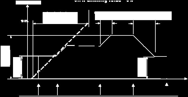
31 07 B0 A2 Switch actuator 982C01 The above figure shows the dimming curves for dimming with dimming value: parameter switching via dimming value = Off if dimming value < min. dimming value The above figure shows the dimming curves for dimming with dimming value: parameter switching via dimming value = On if dimming value > 0% / Off if dimming value = 0% The above figure shows the dimming curves for dimming with dimming value: parameter switching via dimming value = Switching On and switching Off possible Siemens AG 982C01, 32 pages Technical manual Control Products and Systems Siemens AG 2012 Update: /31
Universal Dimmer N 528D01, 2 x 300VA, AC 230 V 5WG DB01
 Gamma instabus Universal Dimmer N 528D01, 2 x 300VA, AC 230 V 5WG1 528-1DB01 Technical Product Information Universal Dimmer for switching or dimming of dimmable lamps Supports dimmable lamps including
0701 CO Light, HVAC, Monitoring, Brightness
 Using the application program Communication objects Product range: Product type: Manufacturer: Name: Order No.: Phys. sensors presence detector Siemens UP 258/21 presence detector 5WG1 258-2AB21 Functional
Connections, displays and operating elements C D E G H. Installing the control unit
 1 2 3 GB Control unit 0-10 V REG-K/3-gang with manual mode Operating instructions Art. no. MTN646991 ¼ DANGER Risk of fatal injury from electrical current. All work on the device should only be carried
Description of the application programme for KNX occupancy detectors version 3.1
 Contents 1. General...1 1.1 Basics for the KNX/EIB BUS...1 1.2 Application versions...1 1.2 Application versions Switchgear application Version 3.1: BEG_SWI_HKL_V3.1 Part numbers: 1.3 Symbols used...1
B.E.G. LUXOMAT KNX-OCCUPANCY DETECTOR
 B.E.G. LUXOMAT KNX-OCCUPANCY DETECTOR GB Contents 1. GENERAL 1 1.1 KNX bus basics 1 1.2. Overview 1 1.3 Symbols 1 2. OCCUPANCY DETECTOR BASICS 2-3 2.1 Introduction 2 2.2 Motion detection with the B.E.G.
Devices for Special Applications
 Overview AP 2/11 UP 2/12 N 26/02 UP 28/11 UP 28/21 N 342 AP24/02 GE 22 GE 23 GE 24 UP 2 AP 2 Control Integrated constant light level control 1-channel 3-channel -- -- -- 1-channel -- -- 1-channel -- 1-channel
Rev KNX Technical Reference Manual Busch Präsenz tech 6131/ /11-500
 0073-1-7613 Rev. 01 06.2011 KNX Technical Reference Manual Busch Präsenz tech 6131/10-500 6131/11-500 KNX Technical Reference Manual Busch Präsenz tech 1 Safety instructions Work on the 230 V power supply
Use of the application program. Functional description. instabus EIB Application program description. October CO Touch-Manager wave
 Use of the application program Product family: Product type: Manufacturer: Display Display units Siemens Name: Touch-Manager wave UP 582 silver, with monochrome display Order no.: 5WG3 582-2AB71 Name:
Technical Manual MDT Motion Detector
 Stand 02/2018 Technical Manual MDT Motion Detector SCN-BWM55.01 SCN-BWM55.G1 Technical Manual Motion Detector SCN-BWM55.x1 1 Content 1 Content... 2 2 Overview... 4 2.1 Overview devices... 4 2.2 Usage &
Tebis application software
 5 Tebis application software STCC530E 2-channel presence detector 360 A faire Product reference Description TP device RF devices TCC530E Bi-zone presence detector TCC530E Output module: Dimmer Loads connected
KNX/EIB - Product database - Application description
 KNX/EIB - Product database - pplication description Theben HTS KNX/EIB Product Database V3.2 for Theben HTS presence detectors ECO-IR 360EIB-C ECO-IR 180EIB-C ECO-IR DUL-EIB compact office EIB compact
PRESENCE DETECTOR. PD-C360i/8 mini KNX PD-C360i/12 mini KNX / 13 7 REMOTE CONTROL PRESENCE DETECTOR
 In the Master function, the remote control entries will be acknowledged as follows: acknowledged 3 x with the red LED In the Slave function, each detection is acknowledged 2 x with the green LED. NOTE:
DOCUMENTATION IPS640
 DOCUMENTATION IPS640 TECHNICAL AND APPLICATION DESCRIPTION Authors: Nebojša Božič, Peter Hauner Last modification: 2017-01-25 2001-2017 Apricum d.o.o. Mažuranićeva 4, 21312 Podstrana, Hrvatska Details,
DOCUMENTATION IPS640
 DOCUMENTATION IPS640 TECHNICAL AND APPLICATION DESCRIPTION Authors: Nebojša Božič, Peter Hauner Last modification: 2018-07-06 2001-2018 Apricum d.o.o. Mažuranićeva 4, 21312 Podstrana, Hrvatska Details,
Operating instructions
 MA00929301 09/2015 Operating instructions ED10429002 ESYLUX GmbH An der Strusbek 40 22926 Ahrensburg Germany info@esylux.com www.esylux.com 1 Table of contents 1 Using the manual 8 2 Safety instructions
UP 258E11 OPTISENS OFFICE
 Product and functional description The UP 258E11 is a presence/motion detector with integrated 2-point light control. The UP 258E11 device communicates via KNX/EIB with actuators or other KNX devices.
User Manual Doc.Ref : JA-KNX-UM. JA-KNX Jablotron KNX Interface ELAUSYS JA-KNX. KNX Interface for Jablotron alarm system.
 Page : 1 of 17. ELAUSYS JA-KNX KNX Interface for Jablotron alarm system User Manual Document history Version. Date Author Comment 1.00 24-JUN-2017 NDE First issue 1.01 14-NOV-2017 NDE Support for user
Application description
 Application description Application description Hersteller KNX Touch Control Hager Displays Touch Displays ETS Touch Control Order number Product designation Application programme TP product SWDT03 WDT030
Product and Applications Description
 Product and Applications Description The presence detector with a sensing range of 360 allows the automatic execution of control functions in the electrical system by detecting movements. For example,
OPERATING INSTRUCTIONS
 4 START-UP All parameter settings are carried out via the ETS (Engineering Tool Software). The magnet provided can be used to activate the programming status for the physical address on the PD-ATMO 360i/8
Sensors SR Programming manual
 Sensors SR510000 Index 1 GENERAL DESCRIPTION... 3 2 TECHNICAL INFORMATION... 4 3 PROGRAMMING... 5 3.1 APPLICATION PROGRAM INFORMATION... 5 3.2 COMMUNICATION OBJECTS TABLE... 5 3.3 OBJECTS DESCRIPTION...
Installer Manual KNX Touchscreen Thermostat
 Installer Manual 02952 KNX Touchscreen Thermostat Index GENERAL FEATURES AND FUNCTIONALITY from page 5 ETS PARAMETERS AND COMMUNICATION OBJECTS from page 7 COMMUNICATION OBJECTS GENERAL FEATURES AND FUNCTIONALITY
Product and Applications Description
 Product and Applications Description Functional description The Dual Sensor provides ambient light level and outdoor temperature values. These values can be sent onto the bus. The device offers four universal
Movement controller comfort, Flush-mounted (Up) xx, xx
 xx, xx") Order no.: 752615xx 752616xx The instabus movement controller comfort is designed for internal use and is pushed onto a flushmounted bus coupling unit (BCU). It reacts to heat movements triggered by persons,
Order no.: 752615xx 752616xx The instabus movement controller comfort is designed for internal use and is pushed onto a flushmounted bus coupling unit (BCU). It reacts to heat movements triggered by persons,
Info-Display xx
 The Info-Display receives telegrams via the instabus EIB and allows the representation (LC display) of freelyprogrammable texts and values. Up to 12 pages with 1, 2 or 4 lines are programmable. A function
User Manual Doc.Ref : EVO-KNX-UM. EVO-KNX Paradox KNX Interface ELAUSYS EVO-KNX. KNX Interface for Paradox alarm system. User Manual.
 Page : 1 of 17. ELAUSYS EVO-KNX KNX Interface for Paradox alarm system User Manual Document history Version. Date Author Comment 1.00 14-AUG-2017 NDE First issue Page : 2 of 17 TABLE OF CONTENT 1. INTRODUCTION
KNX module for smoke alarm devices Dual/VdS and Q-Label (Order no )
") Product definition KNX module for smoke alarm devices Dual/VdS and Q-Label (Order no 2343 00) Art. no 2343 00 Page 1 of 22 Product definition Table of contents 1 Product definition... 3 1.1 Product catalogue...
Product definition KNX module for smoke alarm devices Dual/VdS and Q-Label (Order no 2343 00) Art. no 2343 00 Page 1 of 22 Product definition Table of contents 1 Product definition... 3 1.1 Product catalogue...
Connections, displays and operating elements E F. 20s 3min
 40s 80s 20s 3min 1s 8min KNX FUGA Movement detector 180Art.-Nr. 507D6350, 507D5350, 507D8350 Merten2005V6326-541-0009/09 KNX FUGA Movement detector 180 Operating instructions Connections, displays and
Sensors SR Programming manual
 Sensors SR570000 Index 1 GENERAL DESCRIPTION... 3 2 TECHNICAL INFORMATION... 4 3 PROGRAMMING... 5 3.1 APPLICATION PROGRAM INFORMATION... 5 3.2 COMMUNICATION OBJECTS... 5 3.3 OBJECTS DESCRIPTION... 6 3.4
High bay PIR presence detector 1-10V dimming. PIR Sensor. IR Receiver. Light Level Sensor. Status LEDs. IR Receiver
 Product Guide EBDSPIR-HB-AD High bay PIR presence detector 1-10V dimming Overview The EBDSPIR-HB-AD PIR (passive infrared) presence detector provides automatic control of lighting loads with optional manual
11,9. Ordering data. Max. cable length sensor head 1 basicdim ILD lx 150 lx m 1
 Compact dimensions for luminaire installation For up to 10 DSI or DALI devices (max. 5 per output channel) DALI/DSI output channels with adjustable negative offset from channel to channel 1 Ambient light
RF-KNX / TP-KNX MEDIA COUPLER CO KNX 002
 RF-KNX / TP-KNX MEDIA COUPLER CO KNX 002 INSTRUCTIONS MANUAL Tel.: +34 943627988 E-mail: knx@dinuy.com Web: www.dinuy.com 1 General Description RF-KNX / TP-KNX media coupler. Bidirectional Gateway between
Ceiling PIR presence detector DALI / DSI dimming. PIR Sensor. IR Receiver. Light Level Sensor. Status LEDs. PIR Sensor.
 Product Guide EBDSM-DD Ceiling PIR presence detector DALI / DSI dimming Overview The EBDSM-DD PIR (passive infrared) presence detector provides automatic control of lighting loads with optional manual
Product DELTA i-system DELTA profil titanium white 5WG HB11 pearl grey 5WG AB01 Motion detector
 Product DELTA i-system DELTA profil titanium white 5WG1 258-2HB11 pearl grey 5WG1 255-2AB01 carbon metallic 5WG1 258-2HB21 titanium white 5WG1 255-2AB11 aluminum metallic 5WG1 258-2H1 anthracite 5WG1 255-2AB21
luxcontrol lighting control system basicdim basicdim ILD Compact control module with ambient light sensor and motion sensor
 ILD Compact control module with ambient light sensor and motion sensor Compact dimensions for luminaire installation For up to 10 DSI or DALI devices (max. 5 per output channel) 2 DALI/DSI output channels
Ceiling PIR HS presence detector 1-10V, low temperature. PIR Sensor. IR Receiver. Light Level Sensor. Status LEDs. IR Receiver
 Product Guide EBDHS-AD-LT30 Ceiling PIR HS presence detector 1-10V, low temperature Overview The EBDHS-AD-LT30 PIR (passive infrared) presence detector provides automatic control of lighting loads with
Product Guide. Ceiling PIR HS presence detector DALI / DSI dimming. PIR Sensor. IR Receiver. Light Level Sensor. Status LEDs.
 PPAD-C-HB-DALI-230V Product Guide Ceiling PIR HS presence detector DALI / DSI dimming Overview The PPAD-C-HB-DALI-230V PIR (passive infrared) presence detector provides automatic control of lighting loads
Zone Terminal, 2-fold, FM MT/U , GH Q R0111
 , GH Q631 0060 R0111 SK 0001 B 01 The zone terminal is used for the monitored connection of detectors from security techlogy on the EIB. The device is installed in conventional switch boxes (Ø 55 mm).
11,1 30. Ordering data
 ID Compact control module with ambient light sensor and motion sensor Compact dimensions for luminaire installation For up to 10 DSI or I ballasts I/DSI output channels with adjustable negative offset
High bay PIR presence detector DALI / DSI dimming. PIR Sensor. IR Receiver. Light Level Sensor. Status LEDs. IR Receiver
 EBDSPIR-HB-DD Product Guide High bay PIR presence detector DALI / DSI dimming Overview The EBDSPIR-HB-DD PIR (passive infrared) presence detector provides automatic control of lighting loads with optional
Auro KNX Manual. Auro KNX. Manual. basalte bvba hundelgemsesteenweg 1a 9820 merelbeke belgium. 1 / 23 v basalte
 Auro KNX basalte bvba hundelgemsesteenweg 1a 9820 merelbeke belgium 1 / 23 v0.3 2012 basalte Table of contents 1. Introduction... 3 2. Installation... 4 2.1 Identifying the parts... 5 3. General... 6 3.1
KNX Technical Manual Busch-Presence detector KNX / Busch-Watchdog Sky KNX
 2CKA001473B8668 23.02.2017 KNX Technical Manual Busch-Presence detector KNX / Busch-Watchdog Sky KNX Busch-Presence detector mini KNX 6131/20-xxx-500 Busch-Presence detector mini, premium, KNX 6131/21-xxx-500
DCS2000 DEMENTIA CARE SYSTEM USER GUIDE. For Software Version 1.2 1
 DCS2000 DEMENTIA CARE SYSTEM USER GUIDE For Software Version 1.2 1 Contents 1. INTRODUCTION...3 2. TYPICAL ROOM LAYOUT...4 3. DCS 2000 CONTROL PANEL...5 4. ON / OFF...6 5. SELECTING PROFILES...7 6. STATUS
S INTRUSION&FIRE ALARM AND ACCESS CONTROL PANEL
 S2000-4 INTRUSION&FIRE ALARM AND ACCESS CONTROL PANEL Installer s and User s manual S2000-4 INTRUSION&FIRE AND ACCEESS CONTROL PANEL ATTENTION! To modify configuration parameters use the program uprog.exe
PresenceLight 180A-KNX.. PresenceLight 360A-KNX.. PresenceLight 180B-KNX.. PresenceLight 360B-KNX..
 Presence detector PresenceLight 180A-KNX.. PresenceLight 360A-KNX.. PresenceLight 180B-KNX.. PresenceLight 360B-KNX.. D F GB E I NL S N FIN DK Bedienungsanleitung 2 Notice d utilisation 32 Operating Manual
, ,
 796-2028, 796-2021, 796-2025 Batten mount PIR detectors Overview This series of miniature PIR (passive infrared) presence detectors provide automatic control of lighting loads with optional manual control
THE EVOLUTION OF CONTROL APP & CLOUD PORTAL
 THE EVOLUTION OF CONTROL APP & CLOUD PORTAL APP MAIN APP FUNCTIONS EMERGENCY Facilitates the work of installers and company maintenance operators. Allows control of the functions of all lights of the system.
Product Guide. Ceiling microwave presence detector DALI / DSI. Microwave Sensor. IR Receiver. Light Level Sensor. Status LEDs.
 MPAD-C-DALI-230V Product Guide Ceiling microwave presence detector DALI / DSI Overview The MPAD-C-DALI-230V microwave presence detector provides automatic control of lighting loads with optional manual
Integrated PIR detectors
 EBMINT - Product Guide Integrated PIR detectors Overview The EBMINT series of miniature PIR (passive infrared) presence detectors provide automatic control of lighting loads with optional manual control
Motion detector themova P360 KNX UP WH themova P360 KNX UP GR
 307079 EN Motion detector themova P360 KNX UP WH 1039600 themova P360 KNX UP GR 1039601 1. Product characteristics 4 2. Safety 5 3. Proper use 6 4. Function 6 5. Detection area 10 6. Installation 13 7.
Product and functional description
 Product and functional description The UP 258D11 is a presence/motion detector with inte grated 2 point light control. The UP 258D11 device com municates via KNX/EIB with actuators or other KNX de vices.
PIR/INT & PIR/INT-D. Batten mount PIR detectors. Product Guide. Overview. Features
 Product Guide PIR/INT & PIR/INT-D Batten mount PIR detectors Overview The PIR/INT & PIR/INT-D miniature PIR (passive infrared) presence detectors provide automatic control of lighting loads with optional
Motion detector UP 255, UP 256, UP 257, UP 258 5WG AB 5WG AB 5WG HB
 Product DELTA profil DELTA ambiente DELTA style DELTA i-system Motion detector 5WG1 255-2AB01 pearl grey 5WG1 256-2AB01 arctic white 5WG1 255-2AB11 titanium white 5WG1 258-2HB11 titanium white 5WG1 255-2AB11
2. Safety. 4. Function
 EN Presence detector KNX AP WH 2089550 KNX AP GR 2089551 KNX FLAT DE WH 2089560 KNX FLAT DE GR 2089561 1. Product characteristics 307337 1103092301 Passive infrared presence detector for ceiling Circular
ST3124. KNX Blind Actuator DC 4-fold. Operation and Installation Manual
 ST3124 KNX Blind Actuator DC 4-fold Operation and Installation Manual Date: 2.3.2018 Contents Contents Contents... 2 Introduction... 3 Installation... 4 General... 4 Connection... 4 Wiring Diagram... 5
Tebis application software
 5 Tebis application software STG51x Radio smoke detector STG54x Radio heatstroke Electrical / Mechanical characteristics: see product information Product reference Designation ETS version TP device RF
EBDHS-DD-LT30. Ceiling PIR HS presence detector DALI / DSI, low temperature. Product Guide. Overview. Features
 EBDHS-DD-LT30 Product Guide Ceiling PIR HS presence detector DALI / DSI, low temperature Overview The EBDHS-DD-LT30 PIR (passive infrared) presence detector provides automatic control of lighting loads
Synco-GAMMA Application Guide. Hotel buildings. Answers for infrastructure.
 Synco-GAMMA Application Guide Hotel buildings Answers for infrastructure. Enhanced comfort and energy efficiency in hotels with Synco and GAMMA building systems Requirements Single source Types of integration
How does the Goodnight level work with C-Bus, and how do I use the Goodnight level?
 How does the Goodnight level work with C-Bus, and how do I use the Goodnight level? Overview. One of the most popular C-Bus home automation benefits from Clever Home involves allowing home owners to limit
EBMPIR-MB. Batten mount PIR detectors. Product Guide. Overview. Features
 Product Guide EBMPIR-MB Batten mount PIR detectors Overview The EBMPIR-MB series of miniature PIR (passive infrared) presence detectors provide automatic control of lighting loads with optional manual
600 Watt Dimmer Install Guide
 600 Watt Dimmer Install Guide ER6CD This guide covers all models of the ER6CD lighting controller. The box contents includes the controller with lock nut and installation guide. Overview The ER6CD controller
2CDC D Product manual ABB i-bus KNX LGS/A 1.2 Air Quality Sensor with RTC
 2CDC 508 179 D0201 24.11.2017 Product manual ABB i-bus KNX LGS/A 1.2 Air Quality Sensor with RTC Table of contents Table of contents 1 s on the instruction manual... 12 2 Safety... 13 2.1 Information and
EBMHS (standard & slim-line PSU)
") Product Guide EBMHS (standard & slim-line PSU) Miniature HS PIR Presence Detector (luminaire fitting) Overview The EBMHS series of miniature PIR (passive infrared) presence detectors provide automatic
Product Guide EBMHS (standard & slim-line PSU) Miniature HS PIR Presence Detector (luminaire fitting) Overview The EBMHS series of miniature PIR (passive infrared) presence detectors provide automatic
User manual. ABB i-bus EIB. Zone Terminal MT/S Intelligent Installation System ABB STOTZ-KONTAKT
 User manual ABB i-bus EIB Zone Terminal MT/S 4.12.1 Intelligent Installation System ABB STOTZ-KONTAKT 2 Contents Page 1 Device configuration..................................... 4 1.1 Introduction..........................................
KNX Multitouch Pro. Menu of the KNX Multitouch Pro User manual. This document describes how to operate the user interface of the KNX Multitouch Pro.
 KNX Multitouch Pro User manual This document describes how to operate the user interface of the KNX Multitouch Pro. MTN6215-0310 MTN6215-5910 MTN6216-5910 www.schneider-electric.com Legal information The
Controller - 4 x 1-10 V outputs - BUS/KNX
 87045 LIMOGES Cedex France Telephone: (+33) 05 55 06 87 87 - Fax: (+33) 05 55 06 88 88 Controller - 4 x 1-10 V outputs - Page 1. Use...1. Technical features...1 3. Dimensions.... 4. Connection... 5. Installation...3
FlameGard 5 MSIR HART
 FlameGard 5 MSIR HART Multi-Spectral Infrared Flame Detector HART Communication with the FlameGard 5 Multi-spectral Infrared Detector The information and technical data disclosed in this document may be
Refrigerated air dryers
 Refrigerated air dryers OPERATING AND MAINTENANCE MANUAL Original instructions 38178800319 OPERATING AND MAINTENANCE MANUAL - Contents 1 CONTENTS CONTENTS... 1 Chapter 1 IDRY ELECTRONIC CONTROLLER...
FlameGard 5 UV/IR HART
 FlameGard 5 UV/IR HART HART Communication Manual The information and technical data disclosed in this document may be used and disseminated only for the purposes and to the extent specifically authorized
compact office 24V compact office 24V Lux
 Presence detector compact office 24V compact office 24V Lux Art. Nr. 201 4 000 Art. Nr. 201 4 001 D F GB E I NL S N FIN DK Bedienungsanleitung 2 Notice d utilisation 22 Installation manual 42 Manual de
MWS5. Miniature Microwave Presence Detector (standalone) Product Guide. Overview. Features
 Product Guide. Overview. Features") Product Guide MWS5 Miniature Microwave Presence Detector (standalone) Overview The MWS5 series of miniature microwave presence detectors provide automatic control of lighting loads with optional manual
Product Guide MWS5 Miniature Microwave Presence Detector (standalone) Overview The MWS5 series of miniature microwave presence detectors provide automatic control of lighting loads with optional manual
Product Guide. Ceiling microwave presence detector DALI / DSI. Microwave Sensor. IR Receiver. Light Level Sensor. Status LEDs.
 MPAD-C-A-DALI-230V Product Guide Ceiling microwave presence detector DALI / DSI Overview The MPAD-C-A-DALI-230V microwave presence detector provides automatic control of lighting loads with optional manual
OPERATION MANUAL RK-2006LPP AUGER FITTED SOLID FUEL BOILER TEMPERATURE CONTROLLER. Version DC19
 OPERATION MANUAL RK-2006LPP AUGER FITTED SOLID FUEL BOILER TEMPERATURE CONTROLLER Version DC19 1. Application. Controller RK-2006LPP is designed for temperature control of solid fuel fired water boilers
luxcontrol lighting control system basicdim basicdim ILD 16DPI 69f Compact control module with ambient light sensor and motion sensor
 ILD 16DPI 69f Compact control module with ambient light sensor and motion sensor Product description Compact dimensions for luminaire installation For up to 10 DSI or LI devices (max. 5 per output channel)
Dryer Controller M720
 User Manual Dryer Controller M720 Hardware version 2.00 Software version 2.00 Manual M720 Dryer controller Page 1 of 60 Document history Preliminary version: - Created in April, 2009 Hardware Version 2.00,
GI1DPC/B User Guide. Mains tungsten GLS filament or halogen lamp Min 60W Max 300W. Linear fluorescent
 GI1DPC/B User Guide Single gang PIR Dimmer Replaces a standard light switch or dimmer Turns off automatically Turns on automatically Security mode Night light mode* Scene setting and soft on/off* * only
64.7 Ø85. (1) Sensor inset (2) Lens pluggable. (3) Protection cover (covers the high-voltage terminals). (4) Ceiling (drill hole Ø70mm).
 Sensor inset (2) Lens pluggable. (3) Protection cover (covers the high-voltage terminals). (4) Ceiling (drill hole Ø70mm).") Flush Mount PIR Motion Sensor PIR 1-10V Dimming with Remote Control Mechanical Structure 70mm 64.7 4 56 68.1 73.3 Ø85 3 (1) Sensor inset (2) Lens pluggable Infrared receiver 1 Photocell LED indicator (3)
Flush Mount PIR Motion Sensor PIR 1-10V Dimming with Remote Control Mechanical Structure 70mm 64.7 4 56 68.1 73.3 Ø85 3 (1) Sensor inset (2) Lens pluggable Infrared receiver 1 Photocell LED indicator (3)
Operation Manual Model: Light Switch Combo Universal Dimmer Module Item No.: WMR-252. Specification. Wiring
 Operation Manual Model: Light Switch Combo Universal Dimmer Module Item No.: WMR-252 Featuring an unique universal wireless dimmer module receiver that allows remote controlling existing house hold dimmable
3. Proper use. 4. Function. 1. Product characteristics. 2. Safety. Motion detector
 EN Motion detector KNX DE WH 1039560 KNX DE GR 1039561 KNX AP WH 1039550 KNX AP GR 1039551 307090 The device is maintenance-free. If the device is opened or penetrated with any object, the guarantee lapses.
Ceiling Microwave presence detector - DALI / DSI 12-24V AC/DC. Microwave Sensor. IR Receiver. Light Level Sensor. Status LEDs.
 MWS6-DD-LV Product Guide Ceiling Microwave presence detector - DALI / DSI 12-24V AC/DC Overview The MWS6-DD-LV microwave presence detector provides automatic control of lighting loads with optional manual
WATER HEATER ELECTRONIC CONTROLLER USER MANUAL
 WATER HEATER ELECTRONIC CONTROLLER USER MANUAL UPPER LED READOUT LED ICONS LOWER LED READOUT PVI INDUSTRIES, LLC - Fort Worth, Texas 76111 - Web www.pvi.com - Phone 1-800-433-5654 Page 1 / 7 PV500-40 03/17
VMB1TSW Temperature sensor module for the Velbus system
 VMB1TSW Temperature sensor module for the Velbus system CONTENTS DESCRIPTION... 3 CHARACTERISTICS... 3 VELBUS CHARACTERISTICS... 5 OVERVIEW SENSOR MODULE... 7 EMBEDDING THE TEMPERATURE SENSOR... 8 EMBEDDING
ABB i-bus EIB. Energy-optimised buildings. For authorised electricians only
 ABB i-bus EIB Energy-optimised buildings. For authorised electricians only Preface Flexibility, utilisation value and energy saving are the three main requirements for utility buildings (administration,
LineGuard 2300 Program User Manual (FloBoss 107)
") Form A6251 Part Number D301346X012 November 2012 LineGuard 2300 Program User Manual (FloBoss 107) Remote Automation Solutions Revision Tracking Sheet November 2012 This manual may be revised periodically
Form A6251 Part Number D301346X012 November 2012 LineGuard 2300 Program User Manual (FloBoss 107) Remote Automation Solutions Revision Tracking Sheet November 2012 This manual may be revised periodically
JBE LED2000 INDUSTRIAL SOLUTIONS FOR LED & INCANDESCENT MAINS LIGHTING FLICKER FREE TRAILING EDGE DIMMER
 JBE LED2000 INDUSTRIAL SOLUTIONS FOR LED & INCANDESCENT MAINS LIGHTING FLICKER FREE TRAILING EDGE DIMMER JBE LED Dimming Controller for 110V* & 220V/ 240V AC LED Systems Thank you for purchasing high quality
COCB_ Circuit Breaker (2 state inputs/ 2 control inputs)
") MRS752348-MUM Issued: 0/997 Version: F/23.6.2005 Data subject to change without notice COCB_ Circuit Breaker (2 state inputs/ 2 control inputs) Contents. Introduction... 3. Features... 3.2 Application...
MRS752348-MUM Issued: 0/997 Version: F/23.6.2005 Data subject to change without notice COCB_ Circuit Breaker (2 state inputs/ 2 control inputs) Contents. Introduction... 3. Features... 3.2 Application...
Mounting and Operating Instructions EB 5610 EN. TROVIS 5600 Automation System TROVIS 5610 Heating and District Heating Controller
 TROVIS 5600 Automation System TROVIS 5610 Heating and District Heating Controller Mounting and Operating Instructions Electronics from SAMSON EB 5610 EN Firmware version 1.40 Edition December 2014 Controller
User Manual. Dryer Controller M720
 User Manual Dryer Controller M720 Hardware version 1.00 Software version 1.00 Preliminary version Manual M720 Dryer controller Page 1 of 42 Document history Preliminary version: - Created in April, 2009
Ceiling PIR HS presence detector. Product Guide. Overview. Features
 Product Guide 796-2047 Ceiling PIR HS presence detector Overview The 796-2047 (passive infrared) presence detector provides automatic control of lighting loads with optional manual control. This is a high
IP65 High Bay Dual Sense Sensor
 IP65 High Bay Dual Sense Sensor TM and, Daylight Harvest with Remote Control Technical Data Input Characteristics Sensor Data Model No. Model No. Mains voltage 220-240VAC 50/60Hz Sensor principle High
Install intelligent room automation flexibly and future-proofed
 The world-wide standard for home and building control Install intelligent room automation flexibly and future-proofed Multifunctional, based on KNX room operation devices for the individual requirements
ROOM THERMOSTATS KNX BASIC DOCUMENTATION
 ROOM THERMOSTATS KNX BASIC DOCUMENTATION Contents 2 2 2 2 ABOUT THIS DOCUMENT Document use / request to the reader Target audience, prerequisites Glossary 59 59 60 62 63 HANDLING Mounting and installation
POP_ Smoke Detector
 POP_004308 Smoke Detector Firmware Version : 1.0 Quick Start S This device is a wireless Z-Wave sensor. Exclusion, Inclusion are confirmed by hitting the programm button for 1 sec when the sensor is removed
1 Safety instructions. 2 Device components. Presence detector. Operating instructions
 Presence detector Standard Art. No. 3361 WW Presence detector Standard Art. No. 3361 AL Presende detector Universal Art. No. 3361-1 WW Presende detector Universal Art. No. 3361-1 AL Operating instructions
PPAD-C-230V. Ceiling PIR presence/absence detector. Product Guide. Overview. Features
 Product Guide PPAD-C-230V Ceiling PIR presence/absence detector Overview The PPAD-C-230V passive infrared presence detector provides automatic control of lighting loads with optional manual control. The
DALI MSensor 02 Multi-sensor for DALI system
 MSensor 02 Multi-sensor for system Component of the comfortdim system ( standalone) With ambient light dependent control and motion detection Simple group assignment via rotary switch Multiple MSensors
Local Control Network - building controls in perfection
 Installation guide Local Control Network - building controls in perfection Sensor module for DIN rail mounting The is a sensor module for building installation in Bus technology. It has the same functions
DALI MSensor 02 Multi-sensor for DALI system
 MSensor 02 Multi-sensor for system Product description Component of the comfortdim system ( standalone) With ambient light dependent control and motion detection Simple group assignment via rotary switch
POP_ Smoke Detector
 POP_004308 Smoke Detector Firmware Version : 1.0 Quick Start S This device is a wireless Z-Wave sensor. Exclusion, Inclusion are confirmed by hitting the programm button for 1 sec when the sensor is removed
Stellar Panelboard Dimming Systems
 create a new dimension in lighting control. While lighting systems consume energy, Stellar dimming panels conserve and redirect energy into the atmosphere of your facility. The panel s universal dimmers