Snifter. User Manual. Distributor
|
|
|
- Joel Parsons
- 5 years ago
- Views:
Transcription

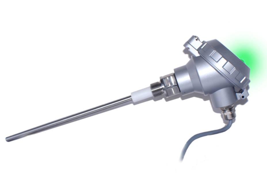

1 Snifter User Manual Distributor Version /09/2009 1
2 Table of Contents 1. INTRODUCTION Safety Product overview How does it work? INSTALLATION Selecting the installation location Installing the sensor WIRING TECHNICAL SPECIFICATION DIMENSIONS OPERATION AUTOMATIC SETUP MAINTENANCE TROUBLESHOOTING The Monitor is not giving relay output signal The Monitor is not responsing after autosetup procedure NOTES
3 1. INTRODUCTION This manual describes how to install and use SINTROL s triboelectric dust monitor Snifter. Sintrol shall not be liable for any loss or damage whatsoever arising from use of any information or details therein, or omission or error in this manual, or any misuse of the product. 1.1 Safety Snifter requires VDC power supply. Although 12-24VDC voltage level is considered safe, but the process gas or dust particulates can be hazardous to health. Take appropriate precautions when installing the monitor: Unless the process conditions are known to be entirely safe, suitable precautions must be taken before any entry is made into the duct for installation or maintenance purposes. The unit may be installed in ducting, containing particulate, hazardous to health. The particulate may be inflammable, explosive or toxic The gas can be hot and pressurised 1.2 Product overview The Snifter Dust monitor is a microprocessor-based, self-adjusting device, equipped with two alarm relays and indication LED in front cover. The Snifter is designed for filter bag leak detection. It can also be used to detect blockage or stoppage in pneumatic transport and bulk solids handling. It is a compact unit with the sensor and control electronics built into one IP65 enclosure, which has been specifically designed for easy installation and operation. The Snifter is designed for applications at up to 2 bar and 140 C. 1.3 How does it work? The Snifter uses proven and reliable triboelectric technology where the interaction of particles with the sensor rod causes a small electrical charge to pass between the particulate and sensor. It is this small electric charge that provides the signal monitored by the electronics, the signal generated is proportional to the dust level even if particles accumulate on the sensor. Experience has shown that this method of monitoring dust level in gasses, offers accurate results with minimum maintenance. 3
4 2. INSTALLATION 2.1 Selecting the installation location The best location for installation of the units of the Snifter is in a section of duct where the particulate has an even distribution and the flow is as laminar as possible. This is to ensure that the sensor rod comes into contact with a representative flow of particles. The ideal position would be in a section of duct that has no bends, valves, dampers or other obstructions for a distance equal to at least three duct diameters downstream or upstream (preferable 5 x duct diameter). See figure 1. Figure 1. Recommended distances to duct bends (DN=Duct Diameter) In some applications, a compromise must be made and the sensor will have to be fitted in a position that satisfies the majority of above requirements. The Snifter must be attached to metal ductwork so that they will be electrically shielded from interference and be provided with a ground reference. 1. The unit shall be installed in a position, where the gas flow passes the sensor rod in a 90 angle. 2. In round cross-section ducts, the unit can be installed in any position above the horizontal axis (between 9 o clock and 3 o clock). See figure 2a. 3. For square cross-section ducts, the unit must be positioned in the middle of the top or in the middle of one of the sides. See figure 2b. 4. Although the sensor is not affected by vibration, very high vibration levels should be avoided. 5. The units must not be installed in direct sunlight or in areas where the ambient temperature is above 60 C. 4

5 The unit above horizontal axis The mounting socket in the middle of the side or in the middle of the top Figure 2a. Round cross-section duct Figure 2b. Square cross-section duct Figure 3. Snifter installed on a duct NOTE! The sensor must not contact the opposite wall or any other obstacle inside the duct. The only allowed interaction with sensor is dust particles. 5
6 2.2 Installing the sensor Once the location of the unit has been selected, the Snifter with BSPT 1/2 male thread can be installed to process adapter with 1/2 female thread. Make sure the installation is in the right position, insert the sensor inside the adapter and rotate the Snifter until the connection is tight. NOTE! Do not over tighten the Snifter with process connection - It may cause damage to sensor and electronics. 3. WIRING Required voltage for Snifter is VDC The snifter comes with two meter power and signal cable ready connected. There are 4 pairs (8 wires) in the same cable, two wires for VDC and two for relays. Remaining four wires are not in use, they are for factory service/diagnostics purposes. Connect the VDC power supply to grey and pink wires. Blue and Red wires are for relays. Blue or Red gives the same voltage like power voltage when relay latches. Both relays must be connected to zero voltage (= 0V) with another wire. CONN1 pin number wire Colour signal name 1 WHITE - 2 BROWN - 3 GREEN - 4 YELLOW - 5 GREY - V- (0 V) 6 PINK - V+ (12-24 VDC) 7 BLUE - relay 1 8 RED - relay 2 Reserved for service/diagnostics 6
7 Cabling Figure 4. Wiring of power and signal cables (1) Voltage + V+ (12-24 VDC) colour PINK (2) Voltage - V- (0VDC) colour GREY (3) Signal out V (12-24 VDC, I max = 170 ma) color BLUE (4) Signal out V (12-24 VDC, I max = 170 ma) colour RED 7
8 4. TECHNICAL SPECIFICATION Snifter specifications Measurement objects Particle size Solid particles in a gas flow 0,3 µm or larger Measurement range from 0,1 mg/m 3 Temperature max 140 C Pressure Gas velocity Humidity Measurement principle Damping time Output signals Alarm settings 2 bar Min. 4 m/s 95% RH (non-condensing) Triboelectric (electrostatic/-dynamic detection) seconds (predefined) 2 solid state relays (170mA and 200mA ) Alert - 5 x normal dust level Alarm - 20 x normal dust level Ambient temperature C Probe Enclosure Protection category Power supply Power consumption Cable (power + signal) Installation Weight SS316 L (220 mm) Aluminium IP VDC 3 W 2 meter 4 pair cable 1/2 BSPT Approx. 0,7 kg This instrument conforms to the following standards Product standard - electrical equipment for measurement, control and laboratory use EMC requirements Reference standard IEC :2005 (First Edition) 8
9 5. DIMENSIONS ½ BSPT Figure 5. Structure and dimensions of Snifter 9


 in normal")


10 6. OPERATION The Snifter Dust Monitor measures the dust level in a gas flow by monitoring electrostatic/-dynamic discharge when charged dust particles hit or pass near by the probe. There are two solid state relay contact alarm outputs and three colour indicator LED in front cover. The alarm relays are arranged such that relay 2 is ON (=connected) in normal operation. Relay 2 turns OFF and relay 1 ON when dust level exceeds 5x normal dust level and both relays are ON when dust level exceeds 20x normal. The alarm threshold factory default values: Alert: > 5x normal dust level = Limit 1 value Alarm: > 20x normal dust level = Limit 2 value Three state of LED indicator GREEN ORANGE RED NORMAL ALERT ALARM dust concentration dust concentration > 5x NORMAL > 20x NORMAL 10
11 Relay and LED indicator functions relay on/off relay state Signal level led indicator operation Both relays OFF Power OFF or fault OFF Power OFF or failure Relay 2 ON (alone) Signal < Limit1 GREEN Normal Relay 1 ON (alone) Limit1 < signal < Limit2 YELLOW Alert Both relays ON signal > Limit 2 RED Alarm 7. AUTOMATIC SETUP To be able to detect variations in dust flow, and to set the alarm so that it will go on if there is excessive dust flow, you must determine the typical dust flow in the application when the process is operating normally. The unit has an AUTOMATIC SETUP function. AUTOMATIC SETUP sets the parameters so, the relays gives the alert when the dust concentration exceeds 5x the typical dust level and an alarm when 20x typical level is exceeded. (See table on page 13) Connect the sensor to the duct connect the power on wait 10 minutes start the auto setup procedure close the cover. For AUTOMATIC SETUP you need to know that the process is running with a normal dust flow rate. Then open the cover of the unit, and initiate AUTOMATIC SETUP by pressing the small button, (see Figure 6). The green LED indicator in front cover starts blinking when AUTOSETUP PROCEDURE is going on. AUTOMATIC SETUP procedure takes up to 10 minutes to be completed, green LED in front cover stops blinking and Snifter is ready for use. 11

12 AUTOSETUP BUTTON Figure 6. Automatic setup button AUTOMATIC SETUP 1. Ensure that the process is in normal conditions. 2. Make sure that the monitor has been connected to process and powered for at least 10 minutes in order to warm up and stabilise! 3. Press the AUTOMATIC SETUP BUTTON (the small button on printed circuit board) Figure Make sure that green LED indicator in front cover starts blinking. NEXT PAGE 5. Turn the cover of enclosure closed and wait for up to 10 minutes until the green LED stops blinking indicating the Automatic Setup sequence has finished. 6. The unit is ready for use. 12
13 8. MAINTENANCE Snifter Dust Monitor needs very little maintenance. To achieve maximum reliable operation the recommended maintenance interval is 2 months. Maintenance is done by removing the unit from the process and cleaning the sensor rod to prevent signal leakage to ground. If the particles in the gas are sticky and tend to build up, the cleaning needs to be done more often. Check the PC board is firmly connected inside the enclosure. Check LED indicator cable and signal/power cable connectors are connected correctly. 9. TROUBLESHOOTING 9.1. The Monitor is not giving relay output signal 1. Check the power and signal wiring are connected correctly. 2. Check there is power on (cover LED glows). 3. Do the auto setup procedure (green LED starts blinking stops when ready). If the monitor is not giving any relay output signal after checks 1, 2 and 3 contact your local distributor The Monitor is not responsing after autosetup procedure 1. Check that there is normal process going on and there were normal operation conditions during auto setup. 2. Check the power and signal wiring are connected correctly. 3. Check the signal is not leaking to ground. - There is NO contact between metal sensor probe and duct wall. - Ensure the gas is not condensing (causes signal leakage) - Check the sticky dust does not build up on the base of the sensor and no bridging between sensor probe and duct wall. 13
14 NOTES 14
15 Sintrol Oy Ruosilantie 15 FI Finland Tel Fax
Snifter ATEX22 VERSION. User Manual. Distributor
 Snifter ATEX22 VERSION User Manual Distributor Version 1.4 09/09/2009 Table of Contents 1. INTRODUCTION... 3 1.1. Safety... 3 1.2. Product overview... 4 1.3. How does it work?... 4 2. INSTALLATION... 5
Sintrol Snifter A1+ Manual. Version 1.2.2
 Sintrol Snifter A1+ Manual Version 1.2.2 Table of Contents 1 INTRODUCTION... 3 1.1 Safety... 3 1.2 Product overview... 3 1.3 How does it work?... 3 2 INSTALLATION... 4 2.1 Selecting the installation location...
Sintrol Snifter A2 EX. Manual. Version 1.2.3
 Sintrol Snifter A2 EX Manual Version 1.2.3 Table of Contents 1 INTRODUCTION... 3 1.1 Safety... 3 1.2 Product overview... 4 1.3 How does it work?... 4 2 INSTALLATION... 4 2.1 Selecting the installation
S304 and S305 Dust Emission Monitors. User Manual. Distributor
 S304 and S305 Dust Emission Monitors User Manual Distributor Version 6.4 30/5/2012 Table of Contents 1. INTRODUCTION... 3 1.1 Safety... 3 1.2 Product overview... 4 1.3 Principle of operation... 4 2. INSTALLATION...
Dusty / Dusty Ex Low-Cost Broken Bag Detection
 EN Operating Instructions Superior Dusty / Dusty Ex Low-Cost Broken Bag Detection SWR engineering Messtechnik GmbH PART OF THE ENVIRONNEMENT S.A GROUP CONTENTS Page 1. Introduction..............................................................
INTRINSICALLY SAFE S314X AND S315X
 INTRINSICALLY SAFE S314X AND S315X Ex SERIES DUST MONITORS Atex models S314X and S315X are not TUV approved versions User Manual Distributor Version 1.3 9.9.2009 Table of Contents 1. INTRODUCTION... 3
MONITORING & CONTROL. the expert approach. Dust Sensors.
 Dust Sensors Continuous Trend Monitoring for Ambient Dust Improve Employee Health Conditions Protect Your Equipment Cost friendly Easy to use Low maintenance Ambient Dust Monitoring Sintrol Dumo Sintrol
ProSens Dust Measurement
 EN Operating Instructions ProSens Dust Measurement SWR engineering Messtechnik GmbH CONTENTS Page 1. Introduction.......................................................................... 3 1.1 Safety............................................................................
THE INDUSTRIAL APPROACH TO DUST MONITORING
 THE INDUSTRIAL APPROACH TO DUST MONITORING Sintrol Oy Finnish owned and run business, founded in 1975 Headquarters: Helsinki, Finland Sales offices: Peking China, Delhi India (10) Branch offices: Russia,
Dust Alert 75. *shown with optional external keypad and display
 Dust Alert 75 Designed to differentiate between gross failure and dust leakage from faulty/failing filter systems including bag filters Automatic internal zero and reference self-checks for regulatory
Duct and Rough Service Carbon Monoxide Sensor
 Product Identification and Overview Duct and Rough Service Carbon Monoxide Sensor BAPI s Carbon Monoxide Sensor offers enhanced electrochemical sensing with outstanding accuracy at low concentrations.
DMFPM-2R MULTIFUNCTIONAL
 Mounting and operating instructions Table of contents SAFETY AND PRECAUTIONS 3 PRODUCT DESCRIPTION 4 ARTICLE CODES 4 INTENDED AREA OF USE 4 TECHNICAL DATA 4 STANDARDS 4 OPERATIONAL DIAGRAMS 5 WIRING AND
RS Pro Infrared Temperature Sensor
 Instruction Manual RS Pro Infrared Temperature Sensor Stock Number: 161-8103 Introduction The RS Pro Infrared Temperature Sensor is a device for measuring the temperature of the surface of a solid or liquid
GL-CO-RFG Channel Gas Leak Alarm System
 Four Elms Road Edenbridge Kent TN8 6AB UK Features & Benefits Remote sensors for natural gas, LPG and CO 1 x SPST relay outputs DIN-rail as standard, panel mounting kit available Adjustable alarm thresholds
OPTISENS TUR 2000 Technical Datasheet
 OPTISENS TUR 2000 Technical Datasheet Sensor for turbidity measurement in water and wastewater Rugged design for harsh applications Integrated transmitter with direct 4...20 ma output Near infrared light
OilSET-1000 (12 VDC)
") Labkotec Oy Myllyhaantie 6 FI-33960 PIRKKALA FINLAND Tel: +358 29 006 260 Fax: +358 29 006 1260 Internet: www.labkotec.fi 20.03.2009 1/11 OilSET-1000 (12 VDC) Oil Separator Alarm Device Copyright 2009
Labkotec Oy Myllyhaantie 6 FI-33960 PIRKKALA FINLAND Tel: +358 29 006 260 Fax: +358 29 006 1260 Internet: www.labkotec.fi 20.03.2009 1/11 OilSET-1000 (12 VDC) Oil Separator Alarm Device Copyright 2009
4-20mA CYBER Cyber Transmitter for flammable, toxic and IR gas detection Cyber Head Increased security in ATEX certified head
 4-20mA CYBER Cyber Transmitter for flammable, toxic and IR gas detection Cyber Head Increased security in ATEX certified head NET DRAFT version 2.1-2008 Pag. 1 4-20mA Cyber - DRAFT version 2.1-2008 Pag.
Sitron s CF Line of Flow Switch Monitors
 Sitron s CF Line of Flow Switch Monitors Models: CF 12AC CF 12DC CF 420 F 420 RCF 420 Introduction Sitron s versatile and intelligent line of Thermal Dispersion Flow Switch Monitors are compact switches,
SET-2000 Hi Level/Oil
 Labkotec Oy Labkotie 1 FI-36240 KANGASALA FINLAND Tel: + 358 29 006 260 Fax: + 358 29 006 1260 13.03.2008 Internet: www.labkotec.fi Alarm Device for Oil Separators Copyright 2008 Labkotec Oy We reserve
Table of Contents 1. OVERVIEW SYSTEM LAYOUT SPECIFICATIONS FUNCTION... 11
 Table of Contents 1. OVERVIEW... 3 2. SYSTEM LAYOUT... 4 3. SPECIFICATIONS... 8 3.1 SYSTEM COMPONENTS...9 3.2 PLC INPUTS AND OUTPUTS...9 3.3 FUNCTION KEYS...10 3.4 DEFAULT SET POINTS AND TIMERS...10 4.
Q-Series Relative Humidity and Relative Humidity & Temperature Sensors for Critical Environments and Outdoor Air
 Document No. 155-755 Q-Series Relative Humidity and Relative Humidity & Temperature Sensors for Critical Environments and Outdoor Air Description Features Application The Q-Series Relative Humidity and
DUAL MONITORED INPUT/OUTPUT UNIT BN-305
 DUAL MONITORED INPUT/OUTPUT UNIT BN-30 Interactive fire detection systems Product Datasheet Features Interactive For interfacing and controlling external units to Autronica s interactive fire detection
PARTICULATE EMISSION MONITORING
 PARTICULATE EMISSION MONITORING CLEAN AIR SOLUTIONS EMP 7 PARTICULATE EMISSION MONITOR CLEAN AIR SOLUTIONS - EMP7 WHAT IT DOES Continuously monitors for filter media leakage EMP7 is a simple self contained
Warranty Registration
 WARRANT Y AND LIMITS OF LIABILIT Y Vulcain Inc. warrants to the original purchaser that its product, and the component parts thereof, will be free from defects in workmanship and materials for a period
Class 1 laser beam sensor safe for your eyes
 113 Sensor SERIES Related Information General terms and conditions... F-7 About laser beam... P.199~ Sensor selection guide... P.1~ General precautions... P.11 PHOTO PHOTO PARTICUR MEASURE ITY panasonic.net/id/pidsx/global
ACTIV8 ONE OFF. 1 Tips USER S GUIDE COMBINED RADAR OPENING AND ACTIVE INFRARED SAFETY SENSOR. 1 Description. 2 Symbols.
 ACTIV8 ONE OFF USER S GUIDE COMBINED RADAR OPENING AND ACTIVE INFRARED SAFETY SENSOR 1 Description Cover 2 nd Radar Antenna Radar motion sensor Push-Buttons IR-Presence sensor Radar Antenna clip IR-Prism
MODEL GPT-130 SINGLE POINT HEAT TRACE CONTROL THERMOSTAT
 TRACON MODEL GPT-130 SINGLE POINT HEAT TRACE CONTROL THERMOSTAT TABLE OF CONTENTS GPT 130 Overview... 2 Installation... 3 Power Source and Load Connection... 4 Temperature Sensor Installation... 5 Panel
ABLOY DA460 SWING DOOR OPERATOR. Installation and commissioning manual
 ABLOY DA460 SWING DOOR OPERATOR Installation and commissioning manual APPROVALS / STANDARDS 73/23/EEC (Low Voltage directive) 93/68/EEC (Low Voltage directive) 89/336/EEC (EMC directive) Statement of fire
Hygro and Hygrothermal Transducers (Capacitive) for Air Conditioning Applications
 for Air Conditioning Applications") Data Sheet 907020 Page 1/9 Hygro and Hygrothermal Transducers (Capacitive) for Air Conditioning Applications For measuring relative humidity and temperature For versatile climatic applications and ventilation
Data Sheet 907020 Page 1/9 Hygro and Hygrothermal Transducers (Capacitive) for Air Conditioning Applications For measuring relative humidity and temperature For versatile climatic applications and ventilation
Class 1 laser beam sensor safe for your eyes
 13 Sensor SERIES Related Information General terms and conditions... F-17 About laser beam... P.13~ Sensor selection guide... P.967~ General precautions... P.1 PHOTO PHOTO Conforming to EMC Directive Conforming
Instruction VIBROCONTROL 850. Single channel vibration monitor. Keep it accessible for future reference.
 Instruction VIBROCONTROL 850 Single channel vibration monitor Keep it accessible for future reference. Copyright 2017 Brüel & Kjaer Vibro GmbH All rights to this technical documentation remain reserved.
OilSET Installation and Operating Instructions. Oil Separator Alarm Device
 Labkotec Oy Myllyhaantie 6 FI-33960 PIRKKALA FINLAND Tel: +358 29 006 260 Fax: +358 29 006 1260 18.11.2010 Internet: www.labkotec.fi 1/10 OilSET-1000 Oil Separator Alarm Device Copyright 2010 Labkotec
SET Installation and Operating Instructions. Level switch for one sensor
 Labkotec Oy Myllyhaantie 6 FI-33960 PIRKKALA FINLAND Tel.: +358 29 006 260 Fax: +358 29 006 1260 7.11.2013 Internet: www.labkotec.fi 1/14 SET-1000 Level switch for one sensor Copyright 2013 Labkotec Oy
WIO200 Water In Oil measuring instrument
 WIO200 Water In Oil measuring instrument You have made the right decision by choosing a measuring instrument from PAJ Systemteknik. Many customers buy our high standard products every year. There are at
Color Mark Sensor. Sensing gdsa distance Spot diameter e. Possible to switch between vertical or horizontal connection using the M12 rotary connector.
 Color Mark Sensor Detects laminated or light-dispersing objects in stable operation without being influenced by mirror reflection. Double indication of the detection level and threshold level allows easy
Additional Operating Instructions SITRANS F. Vortex flowmeters. SITRANS FX330 Ex-nA.
 Additional Operating Instructions SITRANS F Vortex flowmeters Ex-nA Edition 08/207 CONTENTS Safety instructions 3. General notes... 3.2 EU conformity... 3.3 Approval according to the IECEx scheme... 3.4
Original operating instructions Photoelectric safety sensors (safety light curtain / safety light grid) Protected area width (range) 0...
 Protected area width (range) 0...") Original operating instructions Photoelectric safety sensors (safety light curtain / safety light grid) Protected area width (range) 0...12 m OY UK 704555 / 05 02 / 2018 Contents 1 Preliminary note...4
Original operating instructions Photoelectric safety sensors (safety light curtain / safety light grid) Protected area width (range) 0...12 m OY UK 704555 / 05 02 / 2018 Contents 1 Preliminary note...4
MD-MINI Dry Bath. Instruction Manual
 MD-MINI Dry Bath Instruction Manual Catalog No. MD-MINI www.majorsci.com service@majorsci.com Version 01B Revision on: 2013.07.15 Packing list MD-MINI: 1x MD-MINI Dry Bath 1x MD-MINI Lid 1x Power Cord
Carbon Monoxide Transmitter
 Introduction The CO Transmitter uses an electrochemical sensor to monitor the carbon monoxide level and outputs a field-selectable 4-20 ma or voltage signal. The voltage signal may also be set to 0-5 or
TTSIM-1A. TraceTek Sensor Interface Module with Relay. Installation/Operation Instructions. Installation Items (not supplied) Tools Required.
 Tools Required.") TTSIM-1A TraceTek Sensor Interface Module with Relay Installation Items (not supplied) General Information Installation/Operation Instructions Please read these instructions and keep them in a safe place.
TTSIM-1A TraceTek Sensor Interface Module with Relay Installation Items (not supplied) General Information Installation/Operation Instructions Please read these instructions and keep them in a safe place.
Class 1 laser beam sensor safe for your eyes
 1129 PHOTO PHOTO PARTICUR Sensor SERIES Related Information General terms and conditions... F-3 About laser beam... P.193~ guide... P.121~ General precautions... P.19 Conforming to FDA regulations (-11
DUAL MONITORED INPUT/OUTPUT UNIT BN-305-2
 DUAL MONITORED INPUT/OUTPUT UNIT BN-305-2 Interactive fire detection systems Product Datasheet Features Interactive For interfacing and controlling external units to Autronica s interactive fire detection
E3M-V. Mark Sensor. Applications
 Mark Sensor Detects laminated or light-dispersing objects in stable operation without being influenced by mirror reflection. Double indication of the detection level and threshold level allows easy grasp
SET-2000 Oil/Sludge 12 VDC
 Labkotec Oy Myllyhaantie 6 FI-33960 PIRKKALA FINLAND Tel: + 358 29 006 260 Fax: + 358 29 006 1260 12.2.2015 Internet: www.labkotec.fi 1/14 SET-2000 Oil/Sludge 12 VDC Alarm Device for Oil Separators with
Analog Room Pressure Monitor RPC Series
 Description The Room Pressure Monitor is used to measure differential pressure in the range of 0.125 to 1"wc or 30 to 250 Pa. It combines precision high sensitivity silicon sensing capabilities and the
Water Leak Detector BA/LDT Accessories Termination and Troubleshooting
 Overview & Identification The is designed to sense the presence of water and alert a central monitoring system of the potentially destructive situation. Upon water detection, an alarm relay changes state,
Dust Concentration Meter
 Dust Concentration Meter To Sense Breaks or Tears in Filter Bags, to Improve Product Quality, and to Eliminate related Environmental and Safety Risks Triboelectric Dust Monitor Particles in the air are
Gas cylinder scale Model GCS-1
 Electronic pressure measurement Gas cylinder scale Model GCS-1 WIKA data sheet PE 87.19 Applications Level measurement of liquid gases in gas cabinets and gas distribution systems Level measurement in
Relationship between Air Volume and Particle Removal No. of 0.5 μm particles (per L) 800 Air volume 1 0.3m 3 /min 600
 800 Air volume 1 0.3m 3 /min 600") Slimmest in the Industry: High-speed Dust Control Unique twin-fan construction. HEPA filter with high filtration. Be sure to read Safety Precautions on page 1250. Features Clean Slimmest in the industry:
Slimmest in the Industry: High-speed Dust Control Unique twin-fan construction. HEPA filter with high filtration. Be sure to read Safety Precautions on page 1250. Features Clean Slimmest in the industry:
SET-2000 Oil/Sludge. Alarm Device for Oil Separators. Installation and Operating Instructions
 SET-000 Oil/Sludge Alarm Device for Oil Separators Copyright 007 Labkotec Oy We reserve the right for changes without notice TABLE OF CONTENTS GENERAL... INSTALLATION... 4. SET-000 Oil/Sludge Control Unit...
Single Point Freeze Protection Heat Trace Control TRACON MODEL FPT 130 Installation and Operation Manual
 We manage heat MANUAL Single Point Freeze Protection Heat Trace Control TRACON MODEL FPT 130 Installation and Operation Manual 1850 N Sheridan Street South Bend, Indiana 46628 (574) 233-1202 or (800) 234-4239
Brivis Touch Controller. Installer Manual
 Brivis Touch Controller Installer Manual Brivis Touch Controller Kit Scope Please read these instructions carefully before installing this product. This manual covers the installation of the wall mounted
Digi-Sense TC9000 Advanced PID and On/Off Temperature Controller with Thermocouple Input
 User Manual 99 Washington Street Melrose, MA 02176 Phone 781-665-1400 Toll Free 1-800-517-8431 Visit us at www.testequipmentdepot.com Digi-Sense TC9000 Advanced PID and On/Off Temperature Controller with
LZR -I100/ -I110. LASER SCANNERS for industrial doors. User s Guide for product version 0600 and more
 EN LZR -I00/ -I0 LASER SCANNERS for industrial doors I00: max. detection range of 9.9 m x 9.9 m I0: max. detection range of 5.0 m x 5.0 m User s Guide for product version 0600 and more SAFETY The device
MODEL WIND TRACKER
 MODEL 06201 WIND TRACKER NOVEMBER 2001 MANUAL PN: 06201-90 R. M. YOUNG COMPANY 2801 AERO PARK DRIVE, TRAVERSE CITY, MICHIGAN 49686, USA TEL: (231) 946-3980 FAX: (231) 946-4772 MODEL 06201 WIND TRACKER
SERVICE AND INSTALLATION MANUAL MODELS HDO(H) OIL FOR YOUR SAFETY
 OIL FOR YOUR SAFETY") Bousquet Technologies Inc. 2121, Nobel, Ste Julie, Quebec, Canada, J3E1Z9 SERVICE AND INSTALLATION MANUAL MODELS HDO(H) OIL Oil-Fired air heater for industrial and commercial use. FOR YOUR SAFETY Do not
Bousquet Technologies Inc. 2121, Nobel, Ste Julie, Quebec, Canada, J3E1Z9 SERVICE AND INSTALLATION MANUAL MODELS HDO(H) OIL Oil-Fired air heater for industrial and commercial use. FOR YOUR SAFETY Do not
Dual Point General Purpose Heat Trace Control TRACON MODEL GPT 230 Installation and Operation Manual
 We manage heat MANUAL Dual Point General Purpose Heat Trace Control TRACON MODEL GPT 230 Installation and Operation Manual 1850 N Sheridan Street South Bend, Indiana 46628 (574) 233-1202 or (800) 234-4239
Dry Bath Heating Systems
 Dry Bath Heating Systems Instruction Manual N2400-4001 Dry Bath Heating System, Single Block, Digital N2400-4002 Dry Bath Heating System, Dual Block, Digital www.starlabgroup.com DECLARATION OF CONFORMITY
XGUARD-10/-5. LASER SCANNERS for industrial doors. User s Guide for product version 0600 and more
 EN XGUARD-0/-5 LASER SCANNERS for industrial doors XGUARD-0: max. detection range of 9.9 m x 9.9 m XGUARD-5: max. detection range of 5.0 m x 5.0 m User s Guide for product version 0600 and more SAFETY
OMC Ex interface unit. Manual. Version 1.2 August Author: Observator Instruments
 OMC-158-2 Ex interface unit Manual Version 1.2 August 2017 Author: Observator Instruments Revisions: 0.1 (October 2016) First issue 0.2 (December 2016) Prototype 0.3 (January 2017) Test release 1.0 (March
Pipe Freeze Protection Control SCFP-CO-F130 Installation and Operation Manual
 MANUAL Pipe Freeze Protection Control SCFP-CO-F130 Installation and Operation Manual Model FPT 130 Single Point Freeze Protection Heat Trace Control Table of Contents SCFP-CO-F130 Overview... 3 Installation...
OPERATION MANUAL CMW30. Unit Serial Number Range: 0311XXXXCW3 to Present (From March 2011 to Present)
") OPERATION MANUAL CMW30 Unit Serial Number Range: 0311XXXXCW3 to Present (From March 2011 to Present) READ THIS MANUAL CAREFULLY FOR INSTRUCTIONS ON CORRECT INSTALLATION AND USAGE, AND READ ALL SAFEGUARDS.
OPERATION MANUAL CMW30 Unit Serial Number Range: 0311XXXXCW3 to Present (From March 2011 to Present) READ THIS MANUAL CAREFULLY FOR INSTRUCTIONS ON CORRECT INSTALLATION AND USAGE, AND READ ALL SAFEGUARDS.
WIO200 Water in oil sensor
 WIO200 Water in oil sensor User manual Rev. 1.15 Dato: 2011-11-03 Page 1 of 24 TABLE OF CONTENTS Table of contents... 2 Introduction... 3 Safety Advice... 4 Function... 6 Normal operation... 7 Failure
MODEL FPT-130 SINGLE POINT FREEZE PROTECTION HEAT TRACE CONTROL
 TRACON MODEL FPT-130 SINGLE POINT FREEZE PROTECTION HEAT TRACE CONTROL TABLE OF CONTENTS FPT 130 Overview... 2 Installation... 3 Power Source and Load Connections... 4 Temperature Sensor... 5 External
for relative humidity and temperature with calibration certificates
 1 859 1859P01 1859P02 QFA4160 AQF4150 Symaro Room Sensor for relative humidity and temperature with calibration certificates QFA4160 Operating voltage AC 24 V or DC 13.5...3 Signal output DC 0...10 V for
724A. DustAlarm. Broken Bag Detector. DustAlarm ever requires service either in or out of warranty, please
 BUL L E T I N 724A I N S T A L L A T I O N & O P E R A T I O N DustAlarm Broken Bag Detector D u s t A l a r m Thank you for purchasing a quality product manufactured by Monitor Technologies LLC. We realize
FA compressed air plants (refrigeration/adsorption driers) - granulate driers - medical gases - non-corrosive gases, e. g.
 - granulate driers - medical gases - non-corrosive gases, e. g.") INSTRUCTION MANUAL FA 400 Humidity measuring instruments with display and alarm for measurement of the pressure dew point and the atmospheric dew point in different applications: - compressed air plants
INSTRUCTION MANUAL FA 400 Humidity measuring instruments with display and alarm for measurement of the pressure dew point and the atmospheric dew point in different applications: - compressed air plants
TX7130. Conventional Reflective Beam Detector Installation and Operation Manual. TANDA UK Technology Copyright 2015, All right reserved.
 TX7130 Conventional Reflective Beam Detector Installation and Operation Manual Technology Copyright 2015, All right reserved. Product Safety To prevent severe injury and loss of life or property, read
REA 105 Arc Protection Module. Operator s Manual
 REA 105 1MRS 751005-MUM Issued: 20.04.1998 Version: B2/26.5.2000 Checked: Approved: REA 105 We reserve the right to change data without prior notice. Contents: 1. General...4 1.1. Features...4 2. Safety...5
HTC-915-CONT. Heat-Trace Control system
 Heat-Trace Control system Product overview The Raychem HTC-915 system is a compact, full-featured microprocessor-based single-point heat-trace controller. The HTC-915-CONT provides control and monitoring
LZR -I30. max. detection range of 30 ft x 30 ft LASER SCANNERS FOR INDUSTRIAL DOORS LZR-I Page 1 of 12
 EN LZR -I30 LASER SCANNERS FOR INDUSTRIAL DOORS max. detection range of 30 ft x 30 ft 75.5667.07 LZR-I30 0509 Page of SAFETY The device contains IR and visible laser diodes. IR laser: wavelength 905nm;
F17W44_MFB_F_EN INSTALLATION INSTRUCTIONS
 F17W44_MFB_F_EN INSTALLATION INSTRUCTIONS Contents Page User instructions 3-5 General 3 Fan installation 3-4 Maintenance 3 Electrical installation 5 Troubleshooting 5 Technical description 6-8 General
Additional Operating Instructions SITRANS F. Vortex flowmeters. SITRANS FX330 Ex-i.
 Additional Operating Instructions SITRANS F Vortex flowmeters Ex-i Edition 09/2018 CONTENTS 1 Safety instructions 3 1.1 General notes... 3 1.2 EU conformity... 3 1.3 Approval according to the IECEx scheme...
aura-t TP536/GBR ventilation systems
 EN aura-t TP536/GBR Product Manual HRV controller ventilation systems Warnings, Safety information and Guidance Important Information Read instructions fully before the installing this appliance. 1. This
DH400. Accessories. NOTE: Set up for this sensor should be performed by an AAADM-certified installer.
 NOTE: Set up for this sensor should be performed by an AAADM-certified installer. Section 1 General Description The is a high mount microprocessor controlled active infrared presence detector for all types
Manual Comfort Air Curtain
 Manual Comfort Air Curtain Model DF Version 2.0 Original Manual English a COMFORT AIR CURTAIN... Contents 1 Introduction 3 1.1 About this manual 3 1.2 How to read this manual 3 1.3 About the unit 4 1.4
MODEL MARINE WIND TRACKER
 MODEL 06206 MARINE WIND TRACKER NOVEMBER 2001 MANUAL PN 06206-90 R. M. YOUNG COMPANY 2801 AERO-PARK DRIVE, TRAVERSE CITY, MICHIGAN 49686, U. S. A. TEL: (231) 946-3980 FAX: (231) 946-4772 MODEL 06206 MARINE
Danfoss gas detection unit Type GD Heavy Duty
 Data sheet Danfoss gas detection unit Type GD Heavy Duty The Heavy Duty gas detection units are used for monitoring and warning of hazardous Ammonia gas concentrations. They are intended for ATEX/ IECEx
Duct Sensors. Siemens Building Technologies HVAC Products. Symaro. for relative humitidy (high accuracy) and temperature
 and temperature") 1 882 1882P01 Symaro Duct Sensors for relative humitidy (high accuracy) and temperature QFM31 Use Examples Operating voltage AC 24 V / DC 1353 Signal output DC 010 V / 4 20 ma for relative humidity and
1 882 1882P01 Symaro Duct Sensors for relative humitidy (high accuracy) and temperature QFM31 Use Examples Operating voltage AC 24 V / DC 1353 Signal output DC 010 V / 4 20 ma for relative humidity and
MBCE-110/230FR Flame Sensor Module
 MBCE-1001 APRIL 13, 2012 MBCE-110/230FR Flame Sensor Module DESCRIPTION The MBCE-110/230FR modules provide visual indication and electrical outputs that signal the user regarding flame presence in a combustion
FastGene Plate Centrifuge. Instruction Manual. Catalog No. NG
 FastGene Plate Centrifuge Instruction Manual Catalog No. NG040 www.nippongenetics.eu info@nippongenetics.eu Version 01 20.01.2015 Content -1x Plate Centrifuge -2x Adapter for 96 well plates -1x Power Cord
Emitter. Emitting circuit. Control circuit. Check. Monitoring section (CPU) Emitting element failure. Emitting circuit failure
 Emitting element failure. Emitting circuit failure") SF-N SERIES Small Diagnosis Self-diagnosis Test input PNP output type available Type We changed unstable incident beam indicator orange LED) to stable incident beam indicator orange / green LED) from the
SF-N SERIES Small Diagnosis Self-diagnosis Test input PNP output type available Type We changed unstable incident beam indicator orange LED) to stable incident beam indicator orange / green LED) from the
E N G L I S H FIRE ALARM ASPIRATION SENSING TECHNOLOGY QUICK INSTALLATION GUIDE STAND-ALONE FAAST LT MODELS FL0111E FL0112E FL0122E. 367 mm.
 E N G L I S H FIRE ALARM ASPIRATION SENSING TECHNOLOGY QUICK INSTALLATION GUIDE STAND-ALONE FAAST LT MODELS FL0E FL0E FL0E mm mm 0 mm DESCRIPTION The LT FL0 Series is part of the Fire Alarm Aspiration
Installation and Operation Manual
 [Please read this installation & operation manual before install and use this Installation and Operation Manual Address: 8-701,Dongfangming Industry Zone, Dabao Road., Baoan, Shenzhen, China-518101 Page
Please do not hesitate to contact us with any enquiries.
 PRIMARILY DESIGNED TO BE FITTED INTO ANY CARAVAN WITH AN ONBOARD WATER PUMP SUCH AS THE WHALE, SHURFLO OR FIAMMA PUMPS, WHICH MOST CARAVAN MANUFACTURERS FIT AS STANDARD. IDEAL FOR WINTER CARAVANING. THE
POLYMIX PX-IG 2000 Operating Instructions
 POLYMIX PX-IG 2000 Operating Instructions Voltage D 100-120V, 50/60 Hz D 210-250V, 50/60 Hz Please check that the voltage is correct and corresponds with the nameplate on the back of the machine. Manual
WIO 200B and WIOI200B Water in oil sensor
 WIO 200B and WIOI200B Water in oil sensor User manual Rev. 1.11 111881-944 Rev. 1.11 WIO200B User manual Date: 2017-01-20 03-01-0501-CRJ-04 Side 1 af 61 Table of contents Table of contents... 2 Introduction...
PRODUCT CONFORMITY CERTIFICATE
 PRODUCT CONFORMITY CERTIFICATE This is to certify that the StackFlowMaster System Manufactured by: ABB Ltd Oldends Lane Stonehouse Gloucestershire GL10 3TA Has been assessed by Sira Certification Service
LABORATORY OVENS MODELS INCLUDE: TO-152G & TOH-152G TO-152F & TO-235F DEHYDRATING OVENS MODELS INCLUDE: TD-150F TD-330F TD-500F
 0 LABORATORY OVENS MODELS INCLUDE: TO-152G & TOH-152G TO-152F & TO-235F DEHYDRATING OVENS MODELS INCLUDE: TD-150F TD-330F TD-500F WITH WEST 6100 CONTROL 1 IMPORTANT INFORMATION This manual contains operating
Sensor Control Panel
 USER S MANUAL PU SENS 01 Sensor Control Panel V55-6EN-03(SENS).indd 1 18.08.2015 10:37:16 2 PU SENS 01 CONTENTS Safety Requirements 2 Main Technical Data 3 Control Panel Mounting 3 Control Panel Operation
Instructions for the BASIC BCRW Fan, Sizes General
 Instructions for the BASIC BCRW Fan, Sizes 004 027 1. General The BCRW is a direct-driven fan of axi-centrifugal design. This fan offers excellent power efficiency, low, uniform air flow, low sound generation
Installation, Operation and Maintenance Manual
 ECO-1 (AT-EL-1) Single Zone Leak Detection Alarm Panel Installation, Operation & Maintenance Manual ECO-1 (AT-EL-1) Single Zone Leak Detection Alarm Panel Installation, Operation and Maintenance Manual
VIBRA-series: VIBRA, VIBRA +
 DATASHEET VIBRA-series (VIB.00100/..120/..130) VIBRA-series: VIBRA, VIBRA + Profound VIBRA-series Vibrations from pile driving, construction, road or rail traffic, demolition work and blasting can create
SCHMIDT LED Measured Value Display MD Instructions for Use
 SCHMIDT LED Measured Value Display MD 10.010 Instructions for Use Table of Contents 1 Important Information... 3 2 Application range... 4 3 Mounting instructions... 4 4 Electrical connection... 6 5 Signalizations...
LIGHTING TEF 9980 STATUS LIGHT, MAIN LIGHT & REPEATER LIGHT ZONE 1, ZONE 2 & SAFE AREA USER MANUAL
 Subject to change without prior notice TUM7 REV. B.08.08 SAFETY INSTRUCTIONS The TEF 9980 status light may be installed in Zone, or safe area. The Equipment shall not be installed in Zone 0! HANDLE WITH
Air Conditioner. Instruction Manual. For Models WA-1010E, WA-1010H, WA-1010M WA-1230E, WA-1230H P O R T A B L E
 R Instruction Manual For Models WA-1010E, WA-1010H, WA-1010M WA-1230E, WA-1230H P O R T A B L E Air Conditioner It is important that you read these instructions before using your new purchase and we strongly
FlowJam S Ex. Bulk Flow Detection. Operating Instructions. SWR engineering Messtechnik GmbH
 EN FlowJam S Ex Operating Instructions Bulk Flow Detection SWR engineering Messtechnik GmbH CONTENTS Page 1. Function.......................................................................... 3 2. Safety..............................................................................
COMPACT FLAME CONTROLLER CFC 100
 COMPACT FLAME CONTROLLER CFC 100 TECHNICAL DESCRIPTION EDITION: TB CFC100 EN REV. 1 2012-03-07 IMPORTANT: Please note, that all mounting and wiring as well as all changing or adjustment at the flame monitoring
aura-t TP536/EU ventilation systems
 EN aura-t TP536/EU Product Manual HRV controller ventilation systems Warnings, Safety information and Guidance Important Information Read instructions fully before the installing this appliance. 1. This
Dräger Polytron Pulsar 2 Detection of flammable gases and vapours
 Dräger Polytron Pulsar 2 Detection of flammable gases and vapours The Dräger Polytron Pulsar 2 is the latest infrared technology in open path gas detection. Equipped with all the same functions as the standard