ISO-plus-RS4 ISO-plus-CAN
|
|
|
- Marybeth McKenzie
- 5 years ago
- Views:
Transcription


1 ISO-plus-RS4 ISO-plus-CAN User manual
2 Table of contents 1 Safety standards Model identification Technical data Main features Hardware Features Software features Dimensions and Installation Electrical wirings Wiring diagram Leds and key function Meaning of status lights (LED) Key Dip switch Controller functions Loading default values Controller Start / Stop and setpoint modification Automatic tuning Manual tuning AutoTuning Launch Once Synchronized tuning Automatic/Manual regulation for % output control Heater Break Alarm on CT (Current Transformer) Dual Action Heating-Cooling Soft-Start function Retransmission function on analogue output LATCH ON Function Expansion function Serial communication Table of configuration parameters GROUP A - ANALOGUE INPUT Group B - OUTPUT AND REGULATION GROUP C - AUTOTUNING AND P.I.D GROUP D - ALARM GROUP E - ALARM GROUP F - SOFT-START GROUP G - CURRENT TRANSFORMER GROUP H - RETRANSMISSION GROUP I - SERIALE GROUP J - EXPANSION Alarm Intervention Modes Table of Anomaly Signals...41 User manual -- 3
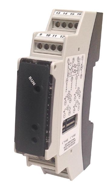
3 Introduction Thanks for choosing is controller. The ISO-RS4 series integrates in a single device the main elements of the control loop: reading of temperature sensor, control output by SSR module, reading and control of the current on the load by means of integrated current CT. Serial communication RS485 and ModbusRTU or CANopen protocol allow the connection to PC/HMI Panels for supervisory functions/remote control. This device is provided with alarms functions, management of double action installation and possibility to be used as expansion controlled by PLC. 1 Safety standards Read carefully the safety guidelines and programming instructions contained in this manual before using/connecting the device. Disconnect power supply before proceeding to hardware settings or electrical wirings. Only qualified personnel should be allowed to use the device and/or service it and in accordance to technical data and environmental conditions listed in this manual. Do not dispose electric tools together with household waste material. In observance European Directive 2002/96/EC on waste electrical and electronic equipment and its implementation in accordance with national law, electric tools that have reached the end of their life must be collected separately and returned to an environmentally compatible recycling facility. 2 Model identification ISO-plus-RS4 ISO-plus-CAN 3 Technical data 3.1 Main features Power supply 24Vdc ±15% + 1 analogue input + 2 logic output 24Vdc/50mA + 1 output 0/4...20mA + RS485 +C.T. Power supply 24Vdc ±15% + 1 analogue input + 2 logic output 24Vdc/50mA + 1 output 0/4...20mA + CANopen +C.T. Operating temperature 0-45 C, humidity uR% Box DIN43880, 18 x 90 x 64 mm Material Box: PC UL94V0 self-extinguishing; front panel: PC UL94V0 self-extinguishing Protection IP20 (box and terminal blocks) Peso Approx. 30 g User manual - - 5
4 3.2 Hardware Features Power supply 24 VDC ±15% Consumption: 3 VA 1: AN1 Configurable via software. Input: Thermocouple type K, S, R, J, T, E, N, B. Automatic compensation of cold junction from C. Thermoresistance: PT100, Analogue input PT500, PT1000, Ni100, PTC1K, Impedence: galvanically insulated NTC10K (β 3435K) V: Ri>110 kω Input V/I: 0-10 V, 0-20 or 4-20 ma, 0-60 mv. Pot. input: Configurable 0-20 ma: Ri<50 Ω 4-20 ma: Ri<50 Ω 0-60 mv: Ri>500 kω kΩ, + 1: C.T. trafo amperimetrico: 50 maac 50/60 Hz Logic output Analogue output galvanically insulated Serial output 3.3 Software features 2 x SSR. Configurable as command or alarm output 1 x 0/4..20 ma. Configurable as command output, alarm output or retransmission RS-485 Mod bus. galvanically insulated Tolerance (25 C) +/-0.3% ±1 digit (su F.s.) for thermocouple, thermoresistance and V / ma. Cold junction accuracy 0.1 C/ C +24VDC ±15%/ 50mA ma: points, ±0.3% on F.S ma points, ±0.3% on F.S. Regulation algorithms ON-OFF with hysteresis. P, PI, PID, PD proportional time. Proportional band C or F Integral time 0,0..999,9 s (0 excludes integral function) Derivative time 0,0..999,9 s (0 excludes derivative function) Controller functions Manual or automatic tuning, configurable alarm, Start/Stop User manual
5 DRR460-12A-T Dimensions and Installation 64 mm 18 mm RUN OUT1 90 mm ON ON OUT Din rail mounting guide EN Electrical wirings This controller has been designed and manufactured in conformity to Low Voltage Directive 2006/95/EC, 2014/35/EU (LVD) and EMC Directive 2004/108/EC, 2014/30/ EU (EMC). For installation in industrial environments please observe following safety guidelines: Separate control line from power wires. Avoid proximity of remote control switches, electromagnetic contactors, powerful engines and use specific filters. Avoid proximity of power groups, especially those with phase control. It is strongly recommended to install adequate mains filter on power supply of the machine where the controller is installed, particularly if supplied 230Vac. The controller is designed and conceived to be incorporated into other machines, therefore CE marking on the controller does not exempt the manufacturer of machines from safety and conformity requirements applying to the machine itself.
6 5.1 Wiring diagram ISO-plus-RS4 5.1.a Power Supply VDC 2 Power supply 24 VDC ±15% 3 VA 5.1.b Analogue Input For thermocouples K, S, R, J, T, E, N, B. + Comply with polarity 13 For possible extensions, use compensated cable AI TC and terminals suitable for the thermocouples 14 used(compensated) Shield / Schermo When shielded cable is used, it should be grounded at one side only Shield / Schermo Rosso For thermoresistances PT100, Ni100. Red 13 For the three-wire connection use wires with the same section Bianco AI White 14 For the two-wire connection short-circuit terminals 13 and 15 When shielded cable is used, it should be grounded at Rosso Red 15 one side only 14 For thermoresistances NTC, PTC, PT500, PT1000 and AI linear potentiometers When shielded cable is used, it should be grounded at one 15 Shield / Schermo side only to avoid ground loop currents + 13 For linear signals in Volt and ma AI V Comply with polarity ma 14 When shielded cable is used, it should be grounded at one Shield / Schermo side only to avoid ground loop currents PT/NI100 PTC/NTC User manual
7 5.1.c Examples of connection for Volt and ma inputs PRESSURE TRANSMITTER / For linear signals 0/4..20 ma with three-wires SENSORE DI PRESSIONE sensors. C 13 Comply with polarity: mA B 14 A= Sensor output B= Sensor ground 2 C= Sensor supply (24VDC) OUT : mA IN :9...33V DC P : mbar Pmax :3bar T :0..70 C A 1 PRESSURE TRANSMITTER / SENSORE DI PRESSIONE C mA B 14 OUT : mA IN :9...33V DC P : mbar Pmax :3bar T :0..70 C External supply / Alimentazione esterna Short circuit pins 2 and 14. For linear signals 0/4..20 ma with external power supply for sensor. Comply with polarity: A= Sensor output B= Sensor ground OUT : mA IN :9...33V DC P : mbar Pmax :3bar T :0..70 C C mA 2 A 1 PRESSURE TRANSMITTER / SENSORE DI PRESSIONE For linear signals 0/4..20 ma with two-wires sensors. Comply with polarity: A= Sensor output C= Sensor supply (24VDC) Short circuit pins 2 and d Serial input TERM 120Ω 9 Shield / Schermo (A) 10 RS485 (B) e CT input 12 CT 16 Communication RS485 Modbus RTU Slave galvanically insulated from the sensor. Short circuit pins 9 and 10 to enter on the bus a 120Ω termination resistance. Input for CT 50mA. Sampling time 100 µs. Current measure true RMS for Heater Break Alarm and overcurrent alarm functions. User manual - 9
8 5.1.f Digital outputs + 5 Q1 24VDC / 50mA 6 + Digital output 24VDC ±15%/ 50mA 7 Q2 24VDC / 50mA g Analogue output + 3 inear output in ma (galvanically insulated from the sensor) AO1 0/4..20mA configurable as command (par. 16 c.out) or retransmission 4 of process-setpoint (par. 100 retr.) 6 Leds and key function 6.1 Meaning of status lights (LED) RUN OUT1 OUT2 Indicates presence of serial communication Normally it indicates the status of output OUT1. During test (pressing key), if the command output is OUT1, blinks with frequency 50ms. At the end of current acquisition by the CT, blinks with frequency 0.5s if the operation has been done successfully. In case of error, it blinks in alternation with the led OUT 2 (ex. broken sensor). Normally indicates the status of output OUT2. During test (pressing key), if the command output is OUT2, blinks with frequency 50ms. At the end of current acquisition by the CT, blinks with frequency 0.5s if the operation has been done successfully In case of error, it blinks in alternation with the led OUT 1 (ex. broken sensor) User manual
. 6.")
9 6.2 Key If pressed it enables the command output: press for more than 3 seconds to manage the threshold current reading for the Heater Break Alarm control. If pressed during the modbus address assignment function, it stores the value assigned by the master (only if the dip1 is all in OFF). 6.3 Dip switch ON ON DIP 1 Slave address If contacts 1..8 are OFF, modbus slave address is selected on parameter 111 sl.ad. Determines modbus slave address, in binary code as indicated below: =1; =2; =3; =4; =5; =6; =7; =125; =126; =127; =128; =129; =130; =251; =252; =253; =254. DIP 2 - Baud rate and loading default values If contacts 1..3 are OFF, modbus baud rate is selected on parameter 112 bd.rt. If contact 4 is ON, parameters and all eeprom datas are loaded with default values (default). Determines modbus baud rate, using following values: 001=4800; 010=9600; 011=19200; 100=28800; 101=38400; 110=57600; 111= Controller functions 7.1 Loading default values This procedure allows to restore default settings as pre-selected at the factory. There are two reset modes: Close contact 4 of the dip switch 2 and reopen it at restart. Write 9999 on word modbus 500. After the restore, device restarts. 7.2 Controller Start / Stop and setpoint modification User can decide if at power-on ISO-plus starts regulation or not, setting parameter 17 init.s. (word 2017). Can modify the controller state writing 1 (start) or 0 (stop) on word It is possibile also to modify command setpoint writing on word 1201, and alarm setpoints on words 1202 and User manual - 11
10 7.3 Automatic tuning Select 1 on parameter 31 (Tune word 2031). Automatic tuning is always active and analyses constantly the difference setpointprocess. If this difference is greater than the value selected on parameter 47 m.g.tu. (Max Gap Tune - word 2047), the ISO-plus decides autonomously when to modify PID parameters. 7.4 Manual tuning Select 2 on parameter 31 (Tune word 2031). The manual procedure allows the user a greater flexibility on deciding when to update PID algorithm parameters. This procedure is activated writing 1 on the word modbus The reference threshold to calculate the new PID parameters is given by the result of the following operation: Tune threshold = Setpoint (word 1201) Par. 32 s.d.tu. (word 2032) Ex.: if setpoint is C and Par. 32 s.d.tu. is 20.0 C, the threshold to calculate PID parameters is ( ) = 80.0 C. N.B.: for greater accuracy in the calculation of PID parameters it is recommended to launch the manual tuning when the process is far from setpoint. 7.5 AutoTuning Launch Once Set 3 on parameter 31 tune (word 2031). Autotuning procedure is executed only once at next ISO-plus restart. If the procedure doesn t work, will be executed at next restart. 7.6 Synchronized tuning Select 4 on parameter 31 (Tune word 2031). This procedure has been conceived to calculate correct PID values on multi-zone systems, where each temperature is influenced by the adjacent zones. Writing on word 1205, the device works as follows: Word 1004 value Action 0 Tune off. 1 Command output OFF 2 Command output ON 3 Tune active 4 Tune completed: command output OFF (read only) 5 Tune not available: softstart function enabled (only reading) The operation of this Tuning mode is the following: the master switches-off or turns-on all zones (value 1 or 2 on word 1205) for a time long enough to create inertia on the system. At this point the autotuning is launched (value 3 on word 1205). The controller calculates the new PID values. When the procedure ends, it switches-off the control output and sets the value 4 on word The master, which should always read the 12 - User manual
11 word 1205, checks the various zones and when all of them have reached the value 4 it will bring to 0 the value of word The various devices will regulate the temperature basing on the new values. N.B. The master must read the Word 1205 at least every 10 seconds or the controller will automatically exit the autotuning procedure. 7.7 Automatic/Manual regulation for % output control This function allows to select automatic functioning or manual command of the output percentage. With parameter 25 (au.ma. word 2025), you can select two methods. 1. The first selection (value 1 of word 2025) allows to modify, through the word 1206, the functioning mode: after writing 1 it is possible to change the output percentage on word 1206 (range ). To return to automatic mode, write 0 on word The second selection (value 2 of word 2025) enables the same functioning, but with two important variants: If there is a temporary lack of voltage or after switch-off, the manual functioning will be maintained as well as the previously set output percentage value. If the sensor breaks during automatic functioning, the controller moves to manual mode while maintaining the output percentage command unchanged as generated by the P.I.D. immediately before breakage. 7.8 Heater Break Alarm on CT (Current Transformer) This function allows to measure load current to manage an alarm during a malfunctioning with power in short circuit, always open or partial break of the charge. To enable this function set 1 (50 Hz) or 2 (60 Hz) on paramater 90 c.t. (word 2090). Set the value of the connected transfomer on parameter 91 c.t. v. (word 2091). Select on par. 92 H,b.a.t. the Heater Break Alarm intervention threshold in Ampere. Otherwise it is possible to select this value in automatic mode pressing for more than 3 seconds. Select on par. 94 H,b.a.d. the delay time in seconds for the Heater Break Alarm intervention. It is possible to associate the alarm to the output OUT2, selecting 10 on par. 56 al. 1. or par. 68 al. 2. It is possible also to enable an overcurrent control, setting on parameter 93 ocu.t. the intervention threshold in Ampere. User manual - 13
12 Dual Action Heating-Cooling This module is suitable also for systems requiring a combined heating-cooling action. The command output has to be configured as PID for Heating (par. 33 p.b. greater than 0), while the alarm 1 and 2 has to be configured as Cooling (value 9 on par. 56 AL. 1 o par. 68 al. 2). The command output must be connected to the actuator responsible for heating, while the alarm will control cooling action. Parameters to be configured for the heating PID are: p.b. (word 2033): Heating proportional band t.i. (word 2034): Integral time of heating and cooling t.d. (word 2035): Derivative time of heating and cooling t.c. (word 2040): Heating time cycle Parameters to be configured for the cooling PID are: AL. 1 (word 2056) or AL. 2 (word 2068) = cool (value 9) Alarm selection (Cooling) p.b.m. (word 2042): Proportional band multiplier ou.d.b. (word 2043): Overlapping / Dead band co.c.t. (word 2044): Cooling time cycle Par. p.b.m. (that ranges from 1.00 to 5.00) determines the proportional band of cooling action basing on the formula: Proportional band for cooling action = p.b. * p.b.m. This gives a proportional band for cooling which will be the same as heating band if p.b.m. = 1.00, or 5 times greater if p.b.m. = Integral and derivative time are the same for both actions. The par. ou.d.b. determines the percentage overlapping between the two actions. For systems in which the heating output and cooling output must never be simultaneously active a dead band (ou.d.b. 0) must be configured, vice versa you can configure an overlapping (ou.d.b. > 0). The following figure shows an example of dual action P.I.D. (heating-cooling) with t.i. = 0 and t.d. = 0. x = COOL SPV PV < 0 (HEAT) ACTIVE COMMAND OUTPUT (HEAT) ACTIVE ALARM OUTPUT (COOL)
13 x = COOL SPV PV = 0 (HEAT) ACTIVE ACTIVE COMMAND OUTPUT (HEAT) ALARM OUTPUT (COOL) x = COOL SPV PV > 0 (HEAT) ACTIVE ACTIVE COMMAND OUTPUT (HEAT) ALARM OUTPUT (COOL) The parameter co.c.t. has the same meaning as the heating time cycle t.c. Par. 41 co o.f. (Cooling Fluid word 2041) pre-selects the proportional band multiplier p.b.m. and the cooling PID cycle time co.c.t. basing on the type of cooling fluid: coo.f. Cooling fluid type p.b.m. co.c.t. Ai r Air oil Oil H2o Water Once selected the parameter coo.f., parameters p.b.m., ou.d.b and co.c.t. can however be modified. User manual - 15
14 7.10 Soft-Start function ISO-plus is provided with two types of softstart selectables on parameter 80 SS.tY. ( Softstart Type word 2080). 1 First selection (value 1 of word 2080) enables gradient softstart. At starting the controller reaches setpoint basing on the rising gradient set on parameter 81 SS.Gr. ( Softstart Gradient word 2081) in Unit/hour (ex. C/h). If parameter 84 SS. ti. ( Softstart Time word 2084) is different to 0, at starting when the time selected on parameter 84 is elapsed, the controller stops to follow the gradient and reaches setpoint with the maximum power. 2 Second selection (value 2 of word 2080) enables output percentual softstart. On par 83 SS.tH. ( Softstart Threshold word 2083) it is possible to set the threshold under which starts the softstart. On parameter 82 SS.PE. ( Softstart Percentage word 2082) an output percentage is selectable (0 to 100), which controller keeps until the process exceeds the threshold set on parameter 83 or until the time in minutes set on parameter 84 SS. ti. ( Softstart Time word 2084) expires Retransmission function on analogue output If not used as command, the anaolgue output can be used to retransmit process/ setpoint/ current read by the C.T. input/ output percentage. Select on parameter 100 retr. ( Retransmission word 2100) the value to be retransmitted. Select on parameter 101 re.ty. ( Retransmission Type word 2101) the type of output. It is possible also to select on parameters 102 and 103 the input value rescale limites LATCH ON Function For use with input po t.1 (potentiometer 6 KΩ) and pot.2 (potentiometer 150 KΩ) and with linear input (0..10 V, mv, 0/4..20 ma), it is possible to associate start value of the scale (parameter 3 Lo.L.i. Lower Linear Input word 2003) to the minimum position of the sensor and value of the scale end (parameter 4 up.l.i. Upper Linear Input word 2004) to the maximum position of the sensor (parameter 1 sul parametro 9 Ltch Latch On word 2009). It is also possible to fix the point in which the controller will display 0 (however keeping the scale range between Lo.L.i. e up.l.i.) using the virtual zero option by setting 2 or 3 in parameter 9 Ltch. Setting 2 virtual zero can be modified in each moment while setting 1, Latch-On function ends after 120 seconds. Then refer to the following table for the calibration procedure: 16 - User manual
15 Press Display Do Write 1 to enable Latch on. Write 0 to end procedure Write 1 to fix value on minimum Write 1 to fix value on maximum Write 1 to fix zero virtual value. Write 2 to reset zero virtual value. Place the sensor on minimum operating value (corresponding to Lo.L.i) Place sensor on maximum operating value (corresponding to up.l.i.) To exit standard procedure write 0 on 1300 or wait 120 seconds. With virtual zero put the sensor on zero point. To exit procedure write 0 on word Expansion function Selecting 1 on parameter 121 E.Mod. ( Expansion Module word 2121) it works as a expansion module. Controller functions (temperature control, alarms, softstart etc..) are disabled and outputs management must be done by an external master (Es. PLC, HMI panel...). It is possible to configure output status at starting and in case of error, programming parameters (see par. 9). Into this mode, refer to modbus words (see par. 8). 8 Serial communication The module xx-t128 is equipped with RS485 and can receive/broadcast data via serial communication using MODBUS RTU protocol. The device can only be configured as a Slave. This function enables the control of multiple controllers connected to a supervisory system/scada. If contacts of dip-switch 1 are all open each controller responds to a Master query only if the query contains the same address as parameter 111 sl.ad.( Slave Address word 2111). The addresses permitted range from 1 to 254 and there must not be controllers with the same address on the same line. Address 255 can be used by the Master to communicate with all the connected equipment (broadcast mode), while with 0 all the devices receive the command, but no response is expected. User manual - 17
16 If Dip-Switch 2 contacts are opened, the baud rate is selected on parameter 112 bd.rt. ( Baud Rate word 2112). Module can introduce a delay (in milliseconds) of the response to the master request. This delay must be set on parameter 114 se.de. ( Serial Delay word 2114). Each parameter modification is saved by the controller in the EEPROM memory ( writing cycles), while the setpoints are saved with a delay of 10 seconds after the last modification. NB: Changes made to words that are different from those reported in the following table can lead to malfunction. Modbus RTU protocol features Selectable on par. 112 bd.rt. Value 0: 4800bit/s Value 4: 38400bit/s Baud-rate Value 1: 9600bit/s Value 5: 57600bit/s Value 2: 19200bit/s Value 6: bit/s Value 3: 28800bit/s Selectable on par. 113 s.p.p. Format Value 0: 8N1 Value 3: 8N2 Value 1: 8E1 Value 4: 8E2 Supported functions Value 2: 8O1 Value 5: 8O2 WORD READING (max 20 word) (0x03, 0x04) SINGLE WORD WRITING (0x06) MULTIPLE WORDS WRITING (max 20 word) (0x10) RO = Read Only R/W = Read/Write WO = Write Only Modbus Read Reset Descrizione address Write value 0 Type of device RO Software version RO Flash 2 Boot version RO Flash 3 Slave address RO Eepr/dip 6 Baud rate RO Eepr/dip 50 Automatic addressing WO - 51 Installation code comparision for automatic learning of slave address WO Loading default values (write 9999) RW Restart (write 9999) RW Process (tenth of degree) RO Command setpoint (tenth of degree) R/W EEPROM 1002 Alarm 1 setpoint (tenth of degree) R/W EEPROM 1003 Start/Stop 0=controller in STOP 1=controller in START R/W User manual
17 Modbus address Descrizione With automatic tuning (word 2005 = 1): 0=autotuning function OFF 1=autotuning in progress With manual tuning (word 2005 = 2): 0=autotuning function OFF 1=autotuning ON With synchronized tuning (word 2005 = 3): 0=autotuning function OFF 1=command out. OFF (forces the cooling) 2=command out. ON (forces the heating) 3=autotuning ON 4=autotuning completed Automatic/manual selection 0=automatic ; 1=manual Output status (0=off, 1=on) Bit 0 = OUT1 Bit 1 = OUT2 Led status (0 = OFF, 1 = ON) Bit0 = Green led Bit1 = Red led OUT1 Bit2 = Red led OUT2 Alarm status (0=absent, 1=present) Bit0 = Allarme 1 Bit1 = Allarme 2 Error flags Bit0 = Cold junction error Bit1 = Process error (sensor) Bit2 = Error in eeprom writing Bit3 = Error in eeprom reading Bit4 = Error missing calibration Bit5 = Generic error Bit6 = Hardware error Bit7 = Error H.B.A. (SSR in short circuit) Bit8 = Error H.B.A. (SSR/open charge) Bit9 = Error H.B.A. (partial break of the charge) Bit10= Overcurrent error Read Write RO 0 R/W 0 R/W 0 R/W 0 RO 0 RO 0 RO 0 RO Cold junction temperature (degree with tenth) RO Command output percentage ( ) Heating output percentage in double loop R/W Cooling output percentage in double loop ( ) RO Current CT (ampere with tenth) RO Current CT ON (ampere with tenth) RO 0 Reset value User manual - 19
18 Modbus Read Reset Descrizione address Write value 1015 Current CT OFF (ampere with tenth) RO Key status (0=rilasciato, 1=premuto) RO Dip 1 value RO Process (if temperature, no tenth) RO Command setpoint (if temperature, no tenth) R/W EEPROM 1102 Alarm 1 setpoint (if temperature, no tenth) R/W EEPROM 1103 Command output percentage (0-1000) Heating output percentage in double loop R/W Heating output percentage (0-100) Heating output percentage in double loop R/W Cooling output percentage in double loop (0-1000) RO Cooling output percentage in double loop (0-100) RO 0 Output status (0=off, 1=on) 1107 Bit 0 = OUT1 RO 0 Bit 1 = OUT Command output percentage ( ) Heating output percentage in doulbe loop R/W Process (if temperature, with tenth) RO? 1201 Command setpoint (if temperature, with tenth) R/W EEPROM 1202 Alarm 1 setpoint (if temperature, with tenth) R/W EEPROM 1203 Alarm 2 setpoint (if temperature, with tenth) R/W EEPROM 1204 Start/Stop 0=controller in STOP R/W 0 1=controller in START With automatic tuning (word 2005 = 1): 0=autotuning function OFF RO 0 1=autotuning in progress With manual tuning (word 2005 = 2): 0=autotuning function OFF R/W =autotuning ON With synchronized tuning (word 2005 = 3): 0=autotuning function OFF 1=command out. OFF (forces the cooling) 2=command out. ON (forces the heating) R/W 0 3=autotuning ON 4=autotuning completed 1206 Automatic/manual selection 0=automatic ; 1=manual R/W Real value (gradient) command setpoint (if temperature, with tenth) R User manual
19 Modbus address Descrizione Alarm status (0=absent, 1=present) Bit0 = Allarme 1 Bit1 = Allarme 2 Command output manual reset: write 0 to reset command output. In reading 0=can not be reset, 1=can be reset Alarms manual reset: write 0 to reset all alarms. In reading 0=can not be reset, 1=can be reset Bit0 = Allarme 1 Bit1 = Allarme 2 Read Write RO 0 R/W 0 R/W Remote alarm 1 state (0=absent, 1=present) R/W Remote alarm 2 state (0=absent, 1=present) R/W AO value by serial (Par.100 = 6) R/W Error flags 1 Bit0 = Cold junction error Bit1 = Process error (sensor) Bit2 = Error in eeprom writing Bit3 = Error in eeprom reading Bit4 = Error missing calibration Bit5 = Generic error Bit6 = Hardware error Bit7 = Error H.B.A. (SSR in short circuit) Bit8 = Error H.B.A. (SSR/open charge) Bit9 = Error H.B.A. (partial break of the charge) Bit10= Overcurrent error Error flags 2 Bit0 = Error eeprom calibrations Bit1 = Error eeprom calibration constants Bit2 = Error eeprom parameters Bit3 = Error eeprom setpoint Bit4 = Error eeprom service datas A Bit5 = Error eeprom service datas B Bit6 = Error eeprom service datas C Command output percentage ( ) Heating output percentage in double loop Cooling output percentage in double loop ( ) Command output percentage (0-1000) Heating output percentage in double loop Cooling output percentage in double loop (0-1000) RO 0 RO 0 R/W 0 RO 0 R/W 0 RO 0 Reset value User manual - 21
20 Modbus address Descrizione Read Write 1220 Command output percentage (0-100) Heating output percentage in double loop R/W Cooling output percentage in double loop (0-100) RO Current CT (ampere with tenth) RO Current media CT (ampere with tenth) RO Current CT ON (ampere with tenth) RO Current CT OFF (ampere with tenth) RO Cold junction temperature (degree with tenth) RO Output status (0=off, 1=on) Bit 0 = OUT1 Bit 1 = OUT2 RO Led status (0 = OFF, 1 = ON) Bit0 = Green led Bit1 = Red led OUT1 Bit2 = Red led OUT2 RO 0 Reset value 1229 Key status (0=rilasciato, 1=premuto) RO Dip 1 value RO Dip 2 value RO Process (if temperature, no tenth) RO Command setpoint (if temperature, no tenth) R/W EEPROM 1234 Alarm 1 Setpoint (if temperature, no tenth) R/W EEPROM 1235 Alarm 2 Setpoint (if temperature, no tenth) R/W EEPROM 1300 Latch on setting R/W Latch on lower limit calibration R/W Latch on upper limit calibration R/W Latch on virtual zero calibration R/W Process (if temperature, with tenth) RO? 1501 CT instantaneous current (ampere with tenth) RO Current CT ON (ampere with tenth) RO Current CT OFF (ampere with tenth) RO Key status (0=rilasciato, 1=premuto) RO Dip 1 value RO Dip 2 value RO Digital output status (0=off, 1=on) Bit 0 = OUT1 Bit 1 = OUT2 R/W Analogue output value R/W Parameter 1 R/W EEPROM 2002 Parameter 2 R/W EEPROM... Parameter... R/W EEPROM 2143 Parameter 143 R/W EEPROM 22 - User manual
21 9 9.1 Table of configuration parameters GROUP A - ANALOGUE INPUT 1 SEN. Sensor (Word modbus 2001) Analogue input configuration / sensor selection 0 Tc-K -260 C C. (Default) 1 Tc-S -40 C C 2 Tc-R -40 C C 3 Tc-J -200 C C 4 Tc-T -260 C..400 C 5 Tc-E -260 C..980 C 6 Tc-N -260 C C 7 Tc-B 100 C C 8 Pt C..600 C 9 Ni C..180 C 10 NTC10K -40 C..125 C 11 PTC1K -50 C..150 C 12 Pt C..600 C 13 Pt C..600 C V ma ma mv 18 Potenziometer (set the value on parameter 5) 2 degr. Degree (Word modbus 2002) 0 C Centigrade (Default) 1 F Fahrenheit 2 K Kelvin 3 Lo.L.i. Lower Linear Input (Word modbus 2003) Range AN1 lower limit only for linear input. Ex: with input ma this parameter takes value associated to 4 ma , Default: 0. 4 up.l.i. Upper Linear Input (Word modbus 2004) Range AN1 upper limit only for linear input. Ex: with input ma this parameter takes value associated to 20 ma Default: Pot.v. Potentiometer Value (Word modbus 2005) Select potentiometer value kohm. Default: 10kohm User manual - 23
22 6 L.i.o.L. Linear Input over Limits (Word modbus 2006) If linear input, allows process to go over limits (Par. 3 and 4). 0 Disabled (Default) 1 Enabled 7 o.cal. Offset Calibration (Word modbus 2007) Value added / subtracted to the process visualization (usually correcting the value of environmental temperature) [digit 1 ] (degrees.tenths for temperature sensors). Default 0. 8 G.caL. Gain Calibration (Word modbus 2008) Percentage value that is multiplied for the process value (allows to calibrated the working point). Ex: to correct the range from C showing C, set the par. to (100.0%) (+100.0%), Default: Ltch Latch-On (Word modbus 2009) Automatic setting of limits for linear inputs and potentiometers. 0 Disabled (Default) 1 Standard 2 Virtual zero 3 Linear virtual zero 10 FLtr. Filter (Word modbus 2010) Analogue input reading filter: increases process stability on word 1000, 1100, 1200, (Default: 1) Reserved Parameters - Group A Reserved parameters - Group A 24 - User manual
23 9.2 Group B - OUTPUT AND REGULATION 16 c.out Command Output (Word modbus 2016) Command output type selection 0 Command Q1; Alarm 1 Q2; Alarm 2 AO (0..20 ma). (Default) 1 Command Q1; Alarm 1 Q2; Alarm 2 AO (4..20 ma). 2 Valve command: Q1 (open) - Q2 (close); Alarm 1 AO (0..20 ma) 3 Valve command: Q1 (open) - Q2 (close); Alarm 1 AO (4..20 ma) 4 Command AO ( ma); Alarm 1 Q1; Allarme 2 Q2. 5 Command AO ( ma); Alarm 1 Q1; Allarme 2 Q2. Comando Allarme 1 Allarme 2 0 Q1 Q2 AO (0..20 ma) 1 Q1 Q2 AO (4..20 ma) 2 Q1(open),Q2(close) AO (0..20 ma) - 3 Q1(open),Q2(close) AO (4..20 ma) - 4 AO (0..20 ma) Q1 Q2 5 AO (4..20 ma) Q1 Q2 17 init.s. Initial State (Word modbus 2017) Selects controller status at starting. 0 Start (Default) 1 Stop 2 Stored. Backs the controller to the Start/Stop status existing before the switching-off. 18 Act.t. Action type (Word modbus 2018) 0 Heating (N.O.) (Default) 1 Cooling (N.C.) 19 c. HY. Command Hysteresis (Word modbus 2019) Hysteresis in ON/OFF [digit] (degrees.tenths for temperature sensors). Default c. S.e. Command State Error (Word modbus 2020) State of contact for command output in case of error. 0 0 ma if command on AO. Open contact if command on Q1. Open valve if valve command. (Default) 1 4 ma if command on AO. Closed contact if command on Q1. Closed valve if valve command ma if command on AO. Open contact if command on Q1. Open valve if valve command ma if command on AO. Closed contact if command on Q1. Closed valve if valve command. User manual - 25
24 21 c. S.s. Command State Stop (Word modbus 2021) State of contact for command output with controller in STOP 0 0 ma if command on AO. Open contact if command on Q1. Open valve if valve command. (Default) 1 4 ma if command on AO. Closed contact if command on Q1. Closed valve if valve command ma if command on AO. Open contact if command on Q1. Open valve if valve command ma if command on AO. Closed contact if command on Q1. Closed valve if valve command. 22 c. re. Command Reset (Word modbus 2022) Type of reset for state of command contact (always automatic in P.I.D. functioning) 0 Automatic reset (Default) 1 Manual reset (by word 1029) 2 Manual reset stored (keeps relay status also after an eventual power failure) 23 c. de. Command Delay (Word modbus 2023) Command delay (only in ON / OFF functioning) seconds. Default: 0. Negative: delay in switching off phase. Positive: delay in activation phase. 24 val.t. Valve Time (Word modbus 2024) Valve time seconds. Default: au.ma. Automatic / Manual (Word modbus 2025) Enable automatic / manual selection. 0 Disabled (Default) 1 Enabled 2 Enabled with memory Reserved Parameters - Group B Reserved parameters - Group B 26 - User manual
25 9.3 GROUP C - AUTOTUNING AND P.I.D. 31 tune. Tune (Word modbus 2031) Autotuning type selection. 0 Disabled. (Default) 1 Automatic. Calculation of P.I.D. parameters at starting and at command setpoint modification. 2 Manual (P.I.D. with automatic parameters calculation by word 1004 or 1205) 3 Once (P.I.D. with parameters calculation only once at starting) 4 Synchronized. 32 s.d.tu. Setpoint Deviation Tune (Word modbus 2032) Selects deviation from command setpoint as threshold used by manual tuning to calculate P.I.D. parameters [digit] (degrees.tenths for temperature sensors). Default: p.b. Proportional Band (Word modbus 2033) Process inertia in units 0 ON / OFF if also t.i. is equal to 0. (Default) [digit] (degrees.tenths for temperature sensors). 34 i.t. Integral Time (Word modbus 2034) Process inertia in seconds. 0 (0.0s) (2000.0s) tenths of second (0 = Integral action disabled), Default 0 35 d.t. Derivative Time (Word modbus 2035) NDerivative time. Normally ¼ of integral time. 0(0.0s) (1000.0s) tenths of second (0 = Derivative action disabled), Default 0 36 d.b. Dead Band (Word modbus 2036) Dead Band [digit] (degrees.tenths for temperature sensors) (Default: 0) 37 p.b.c. Proportional Band Centered (Word modbus 2037) Defines if the proportional band has to be centered on setpoint. In double loop functioning (heating/cooling) is always disabled. 0 Disabled. Band under (heating) or over (cooling) (Default) 1 Centered band User manual - 27
26 38 o.o.s. Off Over Setpoint (Word modbus 2038) In P.I.D. functioning enables the command outoput switching off, when passing a specific threshold (setpoint + Par.37). 0 Disabled. (Default) 1 Enabled 39 of.d.t. Off Deviation Threshold (Word modbus 2039) Selects command setpoint deviation to calculate the intervention threshold of Off Over Setpoint function [digit] (degrees.tenths for temperature sensors) (Default: 0) 40 c.t. Cycle Time (Word modbus 2040) Cycle time (for PID on teleruptor 15s ; for PID on SSR 2s.) seconds (Default:15s) 41 coo.f Cooling Fluid (Word modbus 2041) Type of refrigerant fluid for heating / cooling PID. Enable cooling output on par. AL.1 or AL.2. 0 Air. (Default) 1 Oil 2 Water 42 P. b.m. Proportional Band Multiplier (Word modbus 2042) Proportional band for cooling action is done by the value of par. 30 multiplied for this value. 100(1.00)...500(5.00). Default: 100(1.00) 43 ov.d.b. Overlap / Dead Band (Word modbus 2043) Dead band combination for heating / cooling P.I.D. -200(-20.0%)...500(50.0%) Negative: dead band. Positive: overlapping. Default: 0(0.0%) 44 co.c.t. Cooling Cycle Time (Word modbus 2044) Cycle time for cooling output seconds (Default:10s) 45 L.L.o.P. Lower Limit Output Percentage (Word modbus 2045) Selects min. value for command output percentage. 0%...100%, Default: 0% User manual
27 46 U.L.o.p. Upper Limit Output Percentage (Word modbus 2046) Selects max. value for command output percentage. 0%...100%, Default: 100%. 47 m.g.tu. Max Gap Tune (Word modbus 2047) Selects the max. process-setpoint gap over that the automatic tuning recalculates PID parameters [digit] (degrees.tenths for temperature sensors). Default: mn.p.b. Minimum Proportional Band (Word modbus 2048) Selects the min. proportional band value selectable by the automatic tuning [digit] (degrees.tenths for temperature sensors). Default: ma.p.b. Maximum Proportional Band (Word modbus 2049) Selects the max. proportional band value selectable by the automatic tuning [digit] (degrees.tenths for temperature sensors). Default: mn.i.t. Minimum Integral Time (Word modbus 2050) Selects the min. integral time value selectable by the automatic tuning. 0 (0.0s) (1000.0s) seconds. Default: 400 (40.0s) Reserved Parameters - Group C Reserved parameters - Group C User manual - 29
28 9.4 GROUP D - ALARM 1 56 AL.1 Alarm 1 (Word modbus 2056) The alarm intervention is related to Alarm 1. 0 Disabled. (Default) 1 Absolute alarm (threshold) referred to process active above 2 Absolute alarm (threshold) referred to process active below 3 Band alarm 4 Upper deviation alarm 5 Lower deviation alarm 6 Absolute alarm referred to active setpoint above 7 Absolute alarm referred to active setpoint below 8 Status alarm (active in RUN / START) 9 Cold actuator auxiliary (Cold action in double loop) 10 Heater Break Alarm and Overcurrent Alarm 11 Sensor error. Active alarm in case of broken sensor. 12 Remote. Alarm enabled by word A.I.5. o Alarm 1 State Output (Word modbus 2057) Alarm 1 output contact and intervention type. 0 (N.O. Start) Normally open, active at start (Default) 1 (N.C. Start) Normally closed, active at start 2 (N.O. Threshold) Normally open, active on reaching alarm 1 3 (N.C. Threshold) Normally closed, active on reaching alarm 1 58 a.1.hy. Alarm 1 Hysteresis (Word modbus 2058) [digit] (degrees.tenths for temperature sensors). Default a.1.s. e. Alarm 1 State Error (Word modbus 2059) State of contact for alarm 1 output in case of error. 0 0 ma if alarm 1 on AO. Open contact if alarm 1 on Q1 or Q2. Default 1 4 ma if alarm 1 on AO. Closed contact if alarm 1 on Q1 or Q ma if alarm 1 on AO. Open contact if alarm 1 on Q1 or Q ma if alarm 1 on AO. Closed contact if alarm 1 on Q1 or Q2. 60 a.1.s.s. Alarm 1 State Stop (Word modbus 2060) Alarm 1 output contact state with controller in STOP 0 0 ma if alarm 1 on AO. Open contact if alarm 1 on Q1 or Q2. Default 1 4 ma if alarm 1 on AO. Closed contact if alarm 1 on Q1 or Q ma if alarm 1 on AO. Open contact if alarm 1 on Q1 or Q ma if alarm 1 on AO. Closed contact if alarm 1 on Q1 or Q2. 4 Active alarm in Stop 1 On activation, the output is inhibited if the controller is in alarm mode. Activates only if alarm condition reappers, after that it was restored User manual
29 61 a1. re. Alarm 1 Reset (Word modbus 2061) Alarm 1 contact reset type. 0 Automatic reset (Default) 1 Manual reset (by word 1210) 2 Manual reset stored. (keeps relay status also after an eventual power failure) 62 a.1. d e. Alarm 1 Delay (Word modbus 2062) Alarm 1 Delay seconds. Default: 0. Negative: delay in alarm output phase. Positive: delay in alarm entry phase Reserved Parameters - Group D Reserved parameters - Group D 9.5 GROUP E - ALARM 2 68 AL.2 Alarm 2 (Word modbus 2068) The alarm intervention is related to Alarm 2. 0 Disabled (Default) 1 Absolute alarm (threshold) referred to process active above 2 Absolute alarm (threshold) referred to process active below 3 Band alarm 4 Upper deviation alarm 5 Lower deviation alarm 6 Absolute alarm referred to active setpoint above 7 Absolute alarm referred to active setpoint below 8 Status alarm (active in RUN / START) 9 Cold actuator auxiliary (Cold action in double loop) 10 Heater Break Alarm and Overcurrent Alarm 11 Sensor error. Active alarm in case of broken sensor 12 Remote. Alarm enabled by word 1212 User manual - 31
30 69 A.2.5.o Alarm 2 State Output (Word modbus 2069) Alarm 2 output contact and intervention type. 0 (N.O. Start) Normally open, active at start (Default) 1 (N.C. Start) Normally closed, active at start 2 (N.O. Threshold) Normally open, active on reaching alarm 2 3 (N.C. Threshold) Normally closed, active on reaching alarm 2 70 a.2.hy. Alarm 2 Hysteresis (Word modbus 2070) Alarm 2 Hysteresis [digit] (degrees.tenths for temperature sensors). Default a.2.s.e. Alarm 2 State Error (Word modbus 2071) Contact status for alarm output 2 in case of error 0 0 ma if alarm 1 on AO. Open contact if alarm 1 on Q1 or Q2. Default 1 4 ma if alarm 1 on AO. Closed contact if alarm 1 on Q1 or Q ma if alarm 1 on AO. Open contact if alarm 1 on Q1 or Q ma if alarm 1 on AO. Closed contact if alarm 1 on Q1 or Q2. 72 a.2.s.s. Alarm 2 State Stop (Word modbus 2072) Contact status for alarm output 2 with controller in STOP 0 0 ma if alarm 1 on AO. Open contact if alarm 1 on Q1 or Q2. Default 1 4 ma if alarm 1 on AO. Closed contact if alarm 1 on Q1 or Q ma if alarm 1 on AO. Open contact if alarm 1 on Q1 or Q ma if alarm 1 on AO. Closed contact if alarm 1 on Q1 or Q2. 4 Active alarm in Stop 73 a2.re. Alarm 2 Reset (Word modbus 2073) Alarm 2 contact reset type. 0 Automatic reset (Default) 1 Manual reset (by word 1210) 2 Manual reset stored. (keeps relay status also after an eventual power failure) 74 a.2.de. Alarm 2 Delay (Word modbus 2074) Alarm 2 Delay seconds. Default: 0. Negative: delay in alarm output phase. Positive: delay in alarm entry phase Reserved Parameters - Group E Reserved parameters - Group E 2 On activation, the output is inhibited if the controller is in alarm mode. Activates only if alarm condition reappers, after that it was restored User manual
31 9.6 GROUP F - SOFT-START 80 SS.TY. Soft-Start Type (Word modbus 2080) Enables and selects soft-start type 0 Disabled (Default) 1 Gradient 2 Percentage 81 SS.Gr. Soft-Start gradient (Word modbus 2081) Rise / fall gradient for soft-start Digit/hour (tenths of degree/hour if temperature). (Default: 1000) 82 SS.Pe. Soft-Start Percentage (Word modbus 2082) Value of the output percentage during Soft-start %. (Default: 50%) 83 SS.tH. Soft-Start Threshold (Word modbus 2083) Threshold under which the device enables percentage soft-start function, at starting [digit] (degrees.tenths for temperature sensors) (Default: 1000) 84 SS. ti. Soft-Start Time (Word modbus 2084) Max. softstart duration: if the process doesn t reach the threshold entered on parameter 50 within the selected time, the controller will start to regulate on setpoint value. 0 Disabled minutes. (Default: 15 minutes) Reserved Parameters - Group F Reserved parameters - Group F User manual - 33
32 9.7 GROUP G - CURRENT TRANSFORMER 90 c.t. Current Transformer (Word modbus 2090) Enables C.T. input and selects the net frequency 0 Disabled (Default) 1 50 Hz 2 60 Hz 91 c.t. v. Current Transformer Value (Word modbus 2091) Selects amperometric transformer full-scale Ampere (Default: 50) 92 H.b.a.t. Heater Break Alarm Threshold (Word modbus 2092) Heater Break Alarm activation threshold 0 Alarm disabled. (Default) Ampere. 93 ocu.t. Overcurrent Alarm Threshold (Word modbus 2093) Overcurrent alarm threshold 0 Alarm disabled. (Default) Ampere 94 H.b.a.d. Heater Break Alarm Delay (Word modbus 2094) Delay for Heater Break Alarm and overcurrent alarm s. (Default: 60 s) Reserved Parameters - Group G Reserved parameters - Group G 34 - User manual
33 9.8 GROUP H - RETRANSMISSION 100 retr. Retransmission (Word modbus 2100) Retransmission for output 0/4..20 ma. Parameters 98 and 99 define upper/ lower limit of operating sequence 0 Disabled (Default) 1 Process 2 Command setpoint 3 Alarm 1 setpoint 4 Alarm 2 setpoint 5 Ampere from current transformer 6 Remote value retransmission (word 1213) 101 re.ty. Retransmission Type (Word modbus 2101) Select the type of Retransmission ma ma (Default) 102 Lo.L.r. Lower Limit Retransmission (Word modbus 2102) Linear output lower limit range (value related to 0/4 ma) [digit] (degrees for temperature sensors), Default: up.l.r. Upper Limit Retransmission (Word modbus 2103) Linear output upper limit range (value related to 20 ma) [digit] (degrees for temperature sensors), Default: re.s.e. Retransmission State Error (Word modbus 2104) Selects the value of the analogue output in Volt in case of error 0 0 ma (Default) 1 4 ma 2 20 ma ma 105 re.s.s. Retransmission State Stop (Word modbus 2105) Defines the analogue output value with controller in STOP 0 0 ma (Default) 1 4 ma 2 20 ma ma 4 Retransmission active in STOP Reserved Parameters - Group H Reserved parameters - Group H User manual - 35
34 9.9 GROUP I - SERIALE 111 sl.ad. Slave Address (Word modbus 2111) Selects slave address for serial communication when all DIP 1 contacts are set on OFF Default: bd.rt. Baud Rate (Word modbus 2112) Selects slave address for serial communication when all DIP 2 contacts are set on OFF bit/s bit/s bit/s (Default) bit/s bit/s bit/s bit/s 113 s.p.p. Serial Port Parameters (Word modbus 2113) Selects the type of format for the modbus RTU communication 0 8-N-1 8 bit, no parity, 1 stop bit (Default) 1 8-E-1 8 bit, even parity, 1 stop bit 2 8-O-1 8 bit, odd parity, 1 stop bit 3 8-N-2 8 bit, no parity, 2 stop bit 4 8-E-2 8 bit, even parity, 2 stop bit 5 8-O-2 8 bit, odd parity, 2 stop bit 114 se.de. Serial Delay (Word modbus 2114) Selects the serial delay ms. Default: 0 ms. 115 off.l. Off Line (Word modbus 2115) Selects the off-line time. If no communication is available within the selected time, the controller will switch-off the command output. 0 Offline disabled (Default) tenths of seconds (Es. 100 = 10.0 s) Reserved Parameters - Group I Reserved parameters - Group I 36 - User manual
35 9.10 GROUP J - EXPANSION 121 E.Mod. Expansion Module (Word modbus 2121) Enables Expansion module mode 0 Disabled (Default) 1 Enabled 122 i.va.o. Initial Value Output (Word modbus 2122) Selects output state at starting Bit 0 Q1 (0 = off; 1 = on) Default: 0 Bit 1 Q2 (0 = off; 1 = on) Default: E.Mo.o. Error Mode Output (Word modbus 2123) Defines if the output has to commute into a default state in case of error or off-line. If the error is eliminated, the output keeps the default state. Bit 0 Q1 (0 = unvaried; 1 = commute) Default: 0 Bit 1 Q2 (0 = unvaried; 1 = commute) Default: E.vA.o. Error Value Output (Word modbus 2124) Defines values to be assumed by the outputs in case of error or off-line. Bit 0 Q1 (0 = off; 1 = on) Default: 0 Bit 1 Q2 (0 = off; 1 = on) Default: A.o.ty. Analogue Output Type (Word modbus 2125) Select the type of Analogue Output ma ma (Default) 126 L.L.A.o. Lower Limit Analogue Output (Word modbus 2126) Analogue output lower limit range (value related to 0/4 ma) [digit] Default: u.l.a.o. Upper Limit Analogue Output (Word modbus 2127) Analogue output upper limit range (value related to 20 ma) [digit] Default: i.v.a.o. Initial Value Analogue Output (Word modbus 2128) Selects analogue output value at starting [digit] Default: 0. User manual - 37
36 129 E.M.A.o. Error Mode Analogue Output (Word modbus 2129) Defines if the analogue output has to commute to a default value in case of error or off-line. If the error is eliminated, the output keeps the default value 0 AO unvaried in case of error (Default) 1 AO commuted in case of error 130 E.v.A.o. Error Value Analogue Output (Word modbus 2130) Defines the value assumed by the output in case of error or off-line [digit] Default: C.t.ou. Current Transformer Output (Word modbus 2131) Defines digital output connected to the current transfomer 0 Q1 (Default) 1 Q Reserved Parameters - Group J Reserved parameters - Group J 10 Alarm Intervention Modes 10.a Absolute Alarm or Threshold Alarm (word 2056 = 1) Pv Alarm Spv Hysteresis parameter > 0 Absolute alarm. Hysteresis value greater than 0 (Par. 58 a.1.hy > 0).* Time Off On Off On Alarm output Hysteresis parameter < 0 Alarm Spv Absolute alarm. Hysteresis value less than 0 (Par. 58 a.1.hy > 0).* Time Off On Off On Alarm output 38 - User manual
.* Command setpoint can be modified by RS485 (word 1201). 10.")
37 10.b Allarme assoluto o allarme di soglia riferito al setpoint di comando attivo sopra (word 2056 = 6) Off On Off Comand Spv Hysteresis parameter > 0 Alarm Spv Time Alarm output Absolute alarm referred to command setpoint. Hysteresis value greater than 0 (Par. 58 a.1.hy > 0).* Command setpoint can be modified by RS485 (word 1201). 10.c Allarme di Banda (word 2056 = 3) Pv Hysteresis parameter > 0 Band alarm hysteresis value greater than 0 (Par.58 A.1.HY. > 0).* Pv Off Off Time Alarm output Hysteresis parameter < 0 Comand Spv On On On Off Off Off Alarm Spv Hysteresis parameter Time Alarm output Band alarm hysteresis value less than 0 (Par.58 A.1.HY. > 0).* * The example refers to alarm 1; the function can also be enabled for alarm 2. User manual - 39
The range of ATR243 controllers comes in three versions. Refer to the table below to easily select your preferred model.
 Summary 1 Introduction... 3 2 Model Identification... 3 3 Technical Data... 4 3.1 General Features... 4 3.2 Hardware Features... 4 3.3 Software Features... 5 4 Dimensions and Installation... 5 4.1 Panel
Controller URDR0001 User manual Version 1.0
 Controller URDR0001 User manual Version 1.0 Summary 1 Safety instructions...5 1.1 General instructions...5 1.2 Intended Usage...5 1.3 Qualified personnel...6 1.4 Remaining hazards...6 1.5 CE Conformity...6
02/11/2015
 MIC48 With RS 485 link Part number 89422418 Heating and / or cooling function 2 independent alarms Load break detection 2 setpoint which can be selected remotely Manual / automatic power adjustment RS
02/11/2015
 CTH 46 - CTD 43 / 46 CTD 46 Part number 89422108 CTH 46 Heating / cooling function Measurement and setpoint display CTD 43 Heating or cooling function Measurement display Measurement deviation display-setpoint
ATR 401. Regolatore Controller Manuale Installatore User manual
 ATR 401 Regolatore Controller Manuale Installatore User manual Summary Page 1 Introduction 4 2 Model Identifi cation 4 3 Technical data 5 3.1 General data 5 3.2 Hardware data 5 3.3 Software data 6 4 Dimensions
UR3274 Controller User manual. Version 1.0
 UR3274 Controller User manual Version 1.0 Summary 1 Safety instructions... 5 1.1 General instructions... 5 1.2 Intended Usage... 6 1.3 Qualified personnel... 6 1.4 Remaining hazards... 6 1.5 CE Conformity...
DRR245. Controller - Regolatore. User manual - Manuale installatore
 DRR245 Controller - Regolatore User manual - Manuale installatore Index 1 Safety guide lines...5 2 Model identification...6 3 Technical Data...6 3.1 General data...6 3.2 Hardware data...6 3.3 Software
ATR 171. Regolatore Controller Manuale Installatore User manual
 ATR 171 Regolatore Controller Manuale Installatore User manual Summary Page 1 Introduction 4 2 Model Identifi cation 4 3 Technical Data 5 3.1 General data 5 3.2 Hardware data 5 3.3 Software data 6 4 Dimensions
Temperature Controllers
 Model TEC-4100 1/4 DIN Model TEC-4100 1/4 DIN Temperature Controller Ordering Code: Power Input BOX 1 4 = 90-250 VAC 5 = 11-26 VAC / VDC TEC-4100- Configurable for 4 Programmable Outputs and NEMA 4X/IP65
User manual FRONTAL IP65 1 UNIVERSAL ANALOGIC INPUT 2 RELAY OUTPUTS. 2 TRANSITOR OUTPUTS (PNP) SSR 1 ANALOGIC OUTPUT 0/10V, 4/20mA 2 DIGITAL INPUTS
 SSR 1 ANALOGIC OUTPUT 0/10V, 4/20mA 2 DIGITAL INPUTS") CONTROLLER DIS48-PLUS PROGRAMMING ALSO THROUGH SMARPHONE 1 UNIVERSAL ANALOGIC INPUT 0/10V, 4/20mA, Pt100, Thermocuple mv, ntc10k, PTC1K... 2 DIGITAL INPUTS 1 1 2 2 TIMERS FRONTAL IP65 POWER SUPPLY 24..
CONTROLLER DIS48-PLUS PROGRAMMING ALSO THROUGH SMARPHONE 1 UNIVERSAL ANALOGIC INPUT 0/10V, 4/20mA, Pt100, Thermocuple mv, ntc10k, PTC1K... 2 DIGITAL INPUTS 1 1 2 2 TIMERS FRONTAL IP65 POWER SUPPLY 24..
I/A Series 716C 1/16 DIN Temperature Controller
 Product Specifications I/A Series 716C 1/16 DIN Temperature Controller PSS 2C-1B5 A The Foxboro 716C is a powerful compact, 1/16 DIN, microprocessor-based temperature controller that offers a variety of
Series Temperature Controller Instruction Sheet
 Series Temperature Controller Instruction Sheet Thank you very much for purchasing DELTA A Series. Please read this instruction sheet before using your A series to ensure proper operation and please keep
7EF/7HF/7EC/7ES Temperature Controllers
 7EF/7HF/7E/7ES Temperature ontrollers Dual 4 Digit LED Display Universal Input (6 T/, RTD, mv, V, ma) Autotuning NEMA 4X 100 to 240 Vac Switching Power Supply Algorithms for Heat or Heat/ool ontrol 2 Independent
UDC1000 and UDC1500 MICRO-PRO SERIES UNIVERSAL DIGITAL CONTROLLERS
 UDC1000 and UDC1500 MICRO-PRO SERIES UNIVERSAL DIGITAL CONTROLLERS EN0I-6041 4/01 PRODUCT SPECIFICATION SHEET OVERVIEW The UDC1000 and UDC1500 are microprocessor-based 1/16 DIN and 1/8 DIN controllers
F4 Process Controller Installation and Operation Guide
 F4 Process Controller Installation and Operation Guide 1.Introduction 1.1.Highlight Features Space saving, only 55mm panel depth required Higher sampling rate (1mS) results in better control performance
Nov 08 PRODUCT SPECIFICATION SHEET
 Honeywell UDC1200 and UDC1700 MICRO-PRO SERIES UNIVERSAL DIGITAL CONTROLLERS 51-52-03-35 Nov 08 PRODUCT SPECIFICATION SHEET OVERVIEW The UDC1200 & UDC1700 are microprocessor-based 1/16 DIN and 1/8 DIN
UR3274Sx and UR3274Ax Controller User manual. Version 1.0
 and Controller User manual Version 1.0 Summary 1 Safety instructions... 5 1.1 General instructions... 5 1.2 Intended Usage... 6 1.3 Qualified personnel... 6 1.4 Remaining hazards... 6 1.5 CE Conformity...
OVEN INDUSTRIES, INC.
 OVEN INDUSTRIES, INC. OPERATING MANUAL Model 5C7-252 TEMPERATURE CONTROLLER With PLC Inputs Introduction Thank you for purchasing our controller. The Model 5C7-252 is an exceptionally versatile unit and
VERTEX VT10 SERIES PID OPERATION MANUAL MICROPROCESSOR BASED PID CONTROLLER
 1 VERTEX VT10 SERIES PID OPERATION MANUAL MICROPROCESSOR BASED PID CONTROLLER 1. INTRODUCTION This manual contains information for the installation and operation and tuning of our Vertex VT10 series self-tuning
Series Digital Controller Instruction Sheet
 216/3/11 Series Digital Controller Instruction Sheet Thank you very much for purchasing DELTA DTC Series Temperature Controller. Please read this instruction sheet before using your DTC series to ensure
Micro-controller X C C1 C2 AL1 AL2 AL3. Model: PXR4/5/9. Operation Manual SEL PXR. ECNO:406e
 C C1 C2 AL1 AL2 AL3 Micro-controller X Model: PXR4/5/9 PXR SEL Operation Manual ECNO:46e Table of Contents Part Names and Functions... 6 Operations... 7 2-1 Parameter list... 7 2-2 Basic operations...
CDR-AL Room CO 2 Traffic Light Alarm Units and Sensors
 Product sheet SN1.402 Type CDR-AL CDR-AL Room CO 2 Traffic Light Alarm Units and Sensors CDR-AL sensors are designed to detect carbon dioxide concentration and temperature in the room spaces. The units
Communications None RS-232C RS-422* RS-485* BCD Transmission output*/** (4 to 20 ma) E5AX- E5AX- L(M)A02 L(M)A03
 E5AX- E5AX- L(M)A02 L(M)A03") Digital Controller A 96 x 96-mm (DIN) Digital Process Controller Optimum PID control with feed-forward control circuitry. High accuracy (+0.3% FS +1 digit max.). Replaceable Output Units. Models with communications
Digital Controller A 96 x 96-mm (DIN) Digital Process Controller Optimum PID control with feed-forward control circuitry. High accuracy (+0.3% FS +1 digit max.). Replaceable Output Units. Models with communications
Installation Manual Tracker 221
 Installation Manual Tracker 221 KSR KUEBLER AG Im Kohlstatterfeld 17 D-69439 Zwingenberg / Germany www.ksr-kuebler.com Contents About this Installation Manual...4 Description Tracker 220-series...4 Installing
ATR244. Controller / Regolatore. User manual - Manuale installatore
 ATR244 Controller / Regolatore User manual - Manuale installatore Table of contents 1 Safety guide lines...6 2 Model Identification...7 3 Technical Data...7 3.1 General Features...7 3.2 Hardware Features...8
TEMPERATURE CONTROL MODULE MODEL R3-TC2
 INSTRUCTION MANUAL R3-TC2 TEMPERATURE CONTROL MODULE MODEL R3-TC2 CONTENTS BEFORE USE... 2 POINTS OF CAUTION... 2 COMPONENT IDENTIFICATION... 2 INSTALLATION... 2 EXTERNAL DIMENSIONS unit: mm (inch)...
UDC 700 Universal Digital Controllers and Indicator Specifications
 UDC 700 Universal Digital Controllers and Indicator Specifications 51-52-03-28 August 2002 Overview The UDC 700 is a 1/32 DIN (49 x 25 mm) controller which combines a high degree of technology and quality
RS485 MODBUS Module 8AI
 Version 1.4 15/04/2013 Manufactured for Thank you for choosing our product. This manual will help you with proper support and proper operation of the device. The information contained in this manual have
Universal controller for panel mounting Models CS6S, CS6H, CS6L
 Accessories Universal controller for panel mounting Models CS6S, CS6H, CS6L WIKA data sheet AC 85.08 Applications Plant and industrial furnace construction Process engineering Plastics technology and processing
Process & TeMPerATUre UniversAl input DigiTAl MeTers
 Process & TeMPerATUre UniversAl input DigiTAl MeTers nova PD56 series Thermocouple, rtd, & Process inputs Universal Power supply 1-24 va c Up to 3 Alarm relays retransmitting 4-2 ma output input Max/Min
PROCESS & TEMPERATURE UNIVERSAL INPUT DIGITAL METERS
 PROCESS & TEMPERATURE UNIVERSAL INPUT DIGITAL METERS NOVA PD56 Series Thermocouple, RTD, & Process Inputs Universal Power Supply 1-24 VAC Up to 3 Alarm Relays Retransmitting 4-2 ma Output Input Max/Min
Table of Contents SECTION PAGE
 Table of Contents SECTION PAGE SECTION 1 INTRODUCTION................... 1.1 Description.............................. 1.2 Features................................ 1.3 Models.................................
SA100. General Description. Features. Temperature Controller SA100. Corresponding to Various Applications. Simple Mounting on DIN Rail
 Temperature Controller General Description The is a socket mounting type temperature controller and is available for mounting inside the panel or by easily mounting on DI rail. The has features such as
MO n : 12JMC rév A
 CTT8 MO n : rév A Page 2 / 18 MODIFICATIONS Rev. Description Date Checked by Approuved by Z Creation 2012/02/12 JMC LA A First issue 2012/02/14 JMC LA INDEX Page 3 / 18 GENERALITY 4 INTRODUCTION 4 ACCESSORIES
NOVUS AUTOMATION 1/5. Range: -35 to 720 C (-31 to 1328 F) Range: -90 to 1300 C (-130 to 2372 F) Range: 0 to 1760 C (-32 to 3200 F)
 Range: -90 to 1300 C (-130 to 2372 F) Range: 0 to 1760 C (-32 to 3200 F)") E N R S B Pt100 Pt100 Range: -35 to 720 C (-31 to 1328 F) Range: -90 to 1300 C (-130 to 2372 F) Range: 0 to 1760 C (-32 to 3200 F) Range: 0 to 1760 C (-32 to 3200 F) Range: 150 to 1820 C (302 to 3308 F)
E N R S B Pt100 Pt100 Range: -35 to 720 C (-31 to 1328 F) Range: -90 to 1300 C (-130 to 2372 F) Range: 0 to 1760 C (-32 to 3200 F) Range: 0 to 1760 C (-32 to 3200 F) Range: 150 to 1820 C (302 to 3308 F)
TER Active Room Temperature Sensor (Controller),
,") Product sheet SN1.415 Type TER TER Active Room Temperature Sensors (Controllers) The TER active sensors are designed to detect temperature in the room spaces. The TER sensors have linear 0..10V signals
Product sheet SN1.415 Type TER TER Active Room Temperature Sensors (Controllers) The TER active sensors are designed to detect temperature in the room spaces. The TER sensors have linear 0..10V signals
DIMENS. MIN TYPICAL MAX A 71.0 (2.795) 71.0 (2.795) 71.8 (2.826) B 29.0 (1.141) 29.0 (1.141) 29.8 (1.173)
 71.0 (2.795) 71.8 (2.826) B 29.0 (1.141) 29.0 (1.141) 29.8 (1.173)") Evco S.p.A. Code 104K204E05 page 1/5 EVK204 Digital controller for ventilated refrigerating units, with HACCP and Energy Saving functions version 1.05 GB ENGLISH 1 PREPARATIONS 1.1 Important Please read
Evco S.p.A. Code 104K204E05 page 1/5 EVK204 Digital controller for ventilated refrigerating units, with HACCP and Energy Saving functions version 1.05 GB ENGLISH 1 PREPARATIONS 1.1 Important Please read
CTT8 TEMPERATURE MONITOR DEVICE
 INSTRUCTION MANUAL IM302-U v2.3 CTT8 TEMPERATURE MONITOR DEVICE GENERALITY The device of control temperatures CTT8 is used in the control of electric machine, transformer, motor, etc. where it s possible
User s Guide CN616A. Universal 6 Channel ¼ DIN Process Controller. Shop online at omega.com
 TM User s Guide Shop online at omega.com e-mail: info@omega.com For latest product manuals: www.omegamanual.info CN616A Universal 6 Channel ¼ DIN Process Controller omega.com info@omega.com U.S.A. Headquarters:
ENERGY LIGHT USER S GUIDE ENERGY LIGHT USER S GUIDE
 ENERGY LIGHT USER S GUIDE Release January 2001 CONTENTS 1.0 GENERAL CHARACTERISTICS... 4 1.1 MAIN CHARACTERIS TICS... 4 2.0 USER INTERFACE (CODE C5121230)... 5 2.1 DISPLAY... 5 2.2 MEANING OF THE LEDS...
+ A B V B NO NC V COM PV PV
 + - A + B B - V + - NO NC COM + - + - V + - PV PV Ramp Soak 100 70 50 30 3 5 3 8 5 3 Minute Steam Heating Sensor Cooling Water PID Hotplate Specifications Input power supply AC 100 to 240V, 50/60Hz, DC
Communications* None RS-232C RS-422 RS-485 BCD Transmission output** (4 to 20 ma)
") TEMPERATURE CONTROLLER DIN-sized (96 x 96-mm) Temperature Controller Featuring Advanced PID Control and Heater Burnout Detection Advanced PID control with two degrees of freedom to improve stability and
TEMPERATURE CONTROLLER DIN-sized (96 x 96-mm) Temperature Controller Featuring Advanced PID Control and Heater Burnout Detection Advanced PID control with two degrees of freedom to improve stability and
ABB Instrumentation. Specifications. COMMANDER 150 Universal Process Indicator. the 1 /8 DIN indicator to match all your display requirements
 Specifications COMMANDER 150 Universal Process Indicator High visibility 6-digit LED display the clearest view of your process status 0.1% measurement accuracy precise indication of process measurement
EKC 347 Liquid Level Controller REFRIGERATION AND AIR CONDITIONING. Manual
 EKC 347 Liquid Level Controller REFRIGERATION AND AIR CONDITIONING Manual Contents Introduction...3 Valve compatibility...3 Features...3 Application examples...3 Ordering...3 Operating the EKC 347...4-5
TC515 and TC600 Installation Manual. a Winters company
 THERMOLINE TEMPERATURE CONTROLLERS TC515 and TC600 Installation Manual a Winters company Guarantee 12 months Congratulations on the purchase of this new product. Special care with the design, workmanship
INSTRUCTION MANUAL Micro-computer based digital indicating controller
 INSTRUCTI MANUAL Micro-computer based digital indicating controller TP4A To prevent accidents arising from the misuse of this controller, please ensure the operator using it receives this manual. Caution
Q-SMART MODBUS KIT. Modbus Protocol & Parameters. Cod EN rev.a ed.08/2018. Q-SMART Software Version AE17
 Q-SMART MODBUS KIT Modbus Protocol & Parameters Cod.001085120EN rev.a ed.08/2018 Q-SMART Software Version AE17 Index 1 Modbus Protocol on Q-SMART... 4 1.1 Broadcasting... 4 1.2 Data Protection... 4 1.3
R1000 / R1040 / R1080
 R1000 / R1040 / R1080 1 Zone Temperature Controller: Heat-only Heating-off-cooling Three-point stepping DIN-Format: 96mm x 96mm / 48mm x 96mm / 96mm x 48mm Description and operating manual ELOTECH Industrieelektronik
Communications type RS-232C RS-422 RS-485 E5AJ-A2H02 E5EJ-A2H02
 Temperature Controller Fuzzy Self-tuning Temperature Controller with Advanced PID (2-PID) Control DIN-size: 6 x 6 mm (E5AJ), 2 x 2 mm (E5BJ), 4 x 4 mm (E5CJ), 4 x 6 mm (E5EJ) Fuzzy self-tuning and Auto-tuning
SA200. General Description. Features. Temperature Controller SA200. Self-Tuning Algorithm. Close Vertical or Horizontal Mounting
 Temperature Controller General Description The is a high performance 3 nd DI controller that has been specifically designed for applications where panel space is critical. Though small in size, this controller
PACSystems* RX3i. Thermocouple Input Module, 12 Channels, IC695ALG412. GFK-2578B October 2011
 October 2011 PACSystems* RX3i Thermocouple Input Module, 12 Channels, IC695ALG412 The PACSystems * Thermocouple Input module IC695ALG412 provides twelve isolated differential thermocouple input channels.
Serie Rugghölzli 2 CH Busslingen. Tel. +41 (0) Fax +41 (0)
 Fax +41 (0)") Serie 5000 Tel. +1 (0)5 222 Fax +1 (0)5 222 12 PRODUCT INTRODUCTI PRODUCT INTRODUCTI 5 Series programmable temperature controller is FineTek's mid-range series of controllers. It uses a 12bit analog /
Serie 5000 Tel. +1 (0)5 222 Fax +1 (0)5 222 12 PRODUCT INTRODUCTI PRODUCT INTRODUCTI 5 Series programmable temperature controller is FineTek's mid-range series of controllers. It uses a 12bit analog /
UDC100 Universal Digital Controller Specifications
 UDC100 Universal Digital Controller Specifications 51-52-03-29 November 1999 Overview The UDC100 Universal Digital Controller is a microprocessor-based 1/4 DIN low cost temperature controller. It combines
Instruction manual Micro-computer based digital indicating controller
 Instruction manual Micro-computer based digital indicating controller JCS-33A To prevent accidents arising from the misuse of this controller, please ensure the operator using it receives this manual.
Model 96VTR ¼ DIN Process Controller
 99 Washington Street Melrose, MA 02176 Phone 781-665-1400 Toll Free 1-800-517-8431 Visit us at www.testequipmentdepot.com Back to the Extech 96VTR Product Info Page INSTRUCTION MANUAL Model 96VTR ¼ DIN
N1540 Process Indicator
 N1540 Process Indicator UNIVERSAL INDICATOR INSTRUCTIONS MANUAL V2.0x PRESENTATION N1540 is a quite versatile process indicator. With a wide list of input types - thermocouples, thermo-resistance, voltage
Module Features are-configurable, no module jumpers to set
 December 2011 PACSystems* RX3i Isolated Thermocouple Input Module, 6 Channels, IC695ALG306 Isolated Thermocouple Input Module, 12 Channels, IC695ALG312 Isolated Thermocouple Input module IC695ALG306 provides
Carbon Monoxide Transmitter
 Introduction The CO Transmitter uses an electrochemical sensor to monitor the carbon monoxide level and outputs a field-selectable 4-20 ma or voltage signal. The voltage signal may also be set to 0-5 or
TEMON 4-C. Doc. N MO-0368-ING TEMPERATURE MONITOR DEVICE TYPE TEMON 4-C OPERATION MANUAL. Microener- Copyright 2010 FW 2.1 Date Rev.
 TEMPERATURE MONITOR DEVICE TYPE TEMON 4-C OPERATION MANUAL Microener- Copyright 2010 FW 2.1 Date 01.12.2008 Rev. 0 1. Generality 3 2. Introduction 3 3. Accessories and Options 3 4. Installation 3 5. Connection
Warning Caution INSTRUCTION MANUAL DIN RAIL MOUNTING TYPE INDICATING CONTROLLER
 INSTRUCTI MANUAL DIN RAIL MOUNTING TYPE INDICATING CTROLLER 1 DCL-A DC No.DCLDCE1 2007.01 Thank you for purchasing our DIN rail mounting type indicating controller DCL-A DC. This manual contains instructions
Sequence of operation
 Sequence of operation IPS 4000 secondary variable speed control File No: 90.96 Date: february 21, 2013 Supersedes: new Date: new sequence of operation ips 4000 2 list of abbreviations: adj: Field Adjustable
Temperature Controller
 E5AN Temperature Controller Temperature Controller OMRON Corporation Industrial Automation Company Industrial Devices and Components Division H.Q. Measuring Components Department Shiokoji Horikawa, Shimogyo-ku,
Tempco Part Number PCT30006 Temperature Control Enclosure with Relay Output for Tote Tank Heating Applications
 Instruction Manual Tempco Part Number PCT30006 Temperature Control Enclosure with Relay Output for Tote Tank Heating Applications Manual PCT30006, Revision 9/20/2016 The PCT30006 control enclosure incorporates
ABB MEASUREMENT & ANALYTICS DATA SHEET. C50 1/16 DIN controller / alarm unit
 ABB MEASUREMENT & ANALYTICS DATA SHEET C50 1/16 DIN controller / alarm unit 2 C50 1/16 DI N CON TROLL ER / AL ARM U NIT DS/C 50-E N RE V. M Measurement made easy C50 the 1/16 DIN controller to suit your
VT4810 SINGLE / DUAL ZONE CONTROLLER INSTALLATION MANUAL
 Thermocouple Type BS4937 (IEC584-3): Outer / + / - BS1843 (Old UK Standard) Outer / + / - US Outer / + / - J : Iron / Copper-Nickel Black / Black / White Black / Yellow / Blue Black / White / Red VT4810
General Specifications
 General Specifications GS J0H-0E Model MVHK Digital Limit Alarm (DC Type) with Active Color PV Display General This plug-in type Digital Limit Alarm for DC input receives DC current or DC voltage signal.
Tempco PCT-3000 Series Temperature Control Console with Relay Output for Heating or Cooling Applications
 Instruction Manual Tempco PCT-3000 Series Temperature Control Console with Relay Output for Heating or Cooling Applications Manual PCT-3000 Revision 9/2014 The PCT-3000 series control console incorporates
TEMPERATURE CONTROLLER
 TEMPERATURE CONTROLLER E5CX(-H) DIN-sized super-compact (48 x 48-mm) Temperature Controller Featuring Advanced PID Control Advanced PID control with two degrees of freedom improves stability and response
Series Temperature Controller Instruction Sheet
 Series Temperature Controller Instruction Sheet Thank you very much for choosing Delta DTE series temperature controller. Please read this instruction sheet carefully before using your DTE to ensure proper
TDF 15 MICROPROCESSOR-BASED DIGITAL ELECTRONIC THERMOCONTROLLER. OPERATING INSTRUCTIONS Vr. 01 (ENG) - cod.: ISTR TECNOLOGIC S.p.A.
 - cod.: ISTR TECNOLOGIC S.p.A.") TDF 15 MICROPROCESSOR-BASED DIGITAL ELECTRONIC THERMOCONTROLLER INDEX 1 1.1 1.2 2 2.1 2.2 3 3.1 3.2 3.3 3.4 4 4.1 4.2 4.3 4.4 4.5 4.6 5 5.1 5.2 6 6.1 6.2 6.3 7 7.1 7.2 7.3 7.4 7.5 INSTRUMENT DESCRIPTION
TDF 15 MICROPROCESSOR-BASED DIGITAL ELECTRONIC THERMOCONTROLLER INDEX 1 1.1 1.2 2 2.1 2.2 3 3.1 3.2 3.3 3.4 4 4.1 4.2 4.3 4.4 4.5 4.6 5 5.1 5.2 6 6.1 6.2 6.3 7 7.1 7.2 7.3 7.4 7.5 INSTRUMENT DESCRIPTION
EXD-HP1/2 Stand-alone Superheat/Economizer Controller
 Technical Bulletin EXD-HP1/2 are stand-alone universal superheat and or economizer controllers for heat pumps, heating units, air conditioning and precision cooling such as telecom and shelter applications.
UDC1000 & UDC 1500 MICRO-PRO SERIES UNIVERSAL DIGITAL CONTROLLERS
 UDC1000 & UDC 1500 MICRO-PRO SERIES UNIVERSAL DIGITAL CONTROLLERS EN0I-6041 11/98 PRODUCT SPECIFICATION SHEET OVERVIEW The UDC1000 & UDC 1500 are microprocessor-based 1/16 DIN and 1/8 DIN controllers which
Instruction manual Temperature Controller KT7
 Instruction manual Temperature Controller KT7 No. KT71E7 201.05 To prevent accidents arising from the misuse of this controller, please ensure the operator receives this manual. SAFETY PRECAUTIS Be sure
eed quality electronic design USER s MANUAL
 eed quality electronic design www.dem-it.com eed www.qeed.it info@qeed.it ANALOG SIGNAL DISPLAY Q-DISP-T USER s MANUAL The displays Q-DISP-T, prepared for mounting on the back panel, 96x48mm, will allow
/8 DIN Level Indicator
 Data Sheet SS/_6 High visibility 5-digit LED display clear and accurate indication Analog and relay outputs as standard high, low, latch and rate alarms, plus isolated retransmission Maths functions included
CLEANROOM MONITOR CR3A Network - Installation Instructions
 CLEANROOM MONITOR CR3A Network - Installation Instructions INTRODUCTION The CR3 Series Cleanroom Monitor, was developed specifically to allow for monitoring of confined spaces with accuracy and reliability.
User s Guide. CN616 Series 1 4 DIN Economical 6-Zone PID Temperature Controllers. Shop online at omega.com SM
 User s Guide Shop online at omega.com SM e-mail: info@omega.com For latest product manuals: www.omegamanual.info CN616 Series 1 4 DIN Economical 6-Zone PID Temperature Controllers omega.com info@omega.com
Interchangeable thermistor (THE types) Output Contact E5CS-R1KJX-F E5CS-R1PX-F E5CS-R1GX-F Voltage E5CS-Q1KJX-F E5CS-Q1PX-F E5CS-Q1GX-F
 Output Contact E5CS-R1KJX-F E5CS-R1PX-F E5CS-R1GX-F Voltage E5CS-Q1KJX-F E5CS-Q1PX-F E5CS-Q1GX-F") Temperature Controller 1/16 DIN Sized Controller Offers Selectable Control, Alarm Modes Accurate to ±0.5% of full scale Multiple temperature scale ranges allow flexibility to match application Field-selectable
Temperature Controller 1/16 DIN Sized Controller Offers Selectable Control, Alarm Modes Accurate to ±0.5% of full scale Multiple temperature scale ranges allow flexibility to match application Field-selectable
ST710-KHJV.03. Wiring diagram. Product description. Temperature controller. Order number
 ST71-KHJV.3 Temperature controller Order number 921.8 Wiring diagram Product description The switching outputs of the thermal controller can be programmed as -two-point controller with alarm -three-point
S304 and S305 Dust Emission Monitors. User Manual. Distributor
 S304 and S305 Dust Emission Monitors User Manual Distributor Version 6.4 30/5/2012 Table of Contents 1. INTRODUCTION... 3 1.1 Safety... 3 1.2 Product overview... 4 1.3 Principle of operation... 4 2. INSTALLATION...
DPR-145 TEMPERATURE PROTECTION RELAY. DPR-145 User Manual V-2.0 ( ) PT100 INPUTS: 4 RELAY OUTPUTS: 4 RS-485 MODBUS PORT VDC SUPPLY -1-
 PT100 INPUTS: 4 RELAY OUTPUTS: 4 RS-485 MODBUS PORT VDC SUPPLY -1-") DPR-45 User Manual V-2.0 (2..206) DPR-45 TEMPERATURE PROTECTION RELAY PT00 INPUTS: 4 RELAY OUTPUTS: 4 RS-485 MODBUS PORT 9-50VDC SUPPLY DESCRIPTION DPR-45 is a precision unit designed for the temperature
DPR-45 User Manual V-2.0 (2..206) DPR-45 TEMPERATURE PROTECTION RELAY PT00 INPUTS: 4 RELAY OUTPUTS: 4 RS-485 MODBUS PORT 9-50VDC SUPPLY DESCRIPTION DPR-45 is a precision unit designed for the temperature
TYPE CM-2201 NELSON SINGLE POINT CIRCUIT MANAGEMENT SYSTEM
 2 Line, 16 Characters/row LCD Display Temperature Input Range -50 C to +500 C -58 F to + 932 F Enclosure NEMA Type 4X Current Rating 30A max (resistive load only) Ambient Temperature -40 C to + 40 C -40
4/8/12/16 Channel Temperature Scanner with FREE Data Logging PC Software RS485
 Select Option Device Wise Device/Group HumiLog Y-Axis Text Show/Hide Ledgends MIN MAX Scale Y Max 08-05-2015 15:17:59 PV_C PV_RH Color default default Graph Refresh Interval 2 Set Interval PV Low Alarm
CN4800 Series CONTROLLER
 CN4800 Series CONTROLLER Operator's Manual PV SV OUT1 OUT2 ALM1 ALM2 SEL M1791/0502 Contents I. PREPARING THE OPERATION... 4 1. THE BASIC INSTALLATION PROCEDURE... 5 2. CHECK OF SPECIFICATIONS... 6 2.1
WIO500 and WIOI500 Water in oil sensor
 WIO500 and WIOI500 Water in oil sensor User manual Rev. 1.08 111881-942 Rev. 1.08 User manual 500 Date: 2017-01-20 03-01-0501-CRJ-04 Side 1 af 79 Table of contents Table of contents... 2 Introduction...
ER65-DRW Controller. Heating Applications. Product Bulletin. Heating Controller
 PB_ER65-DRW_ 202 ER65-DRW Controller Heating Applications Product Bulletin The controller is a digital device for domestic or residential heating units. It covers water and air heating applications. All-in-one
Networkable Fan Coil Controller Specification and Installation Instructions
 Controller Models EFCB10T-OE1 (24Vac / 0 relays) EFCB12T-OE1 (240Vac / 0 relays) EFCB10TU4-OE1 (24Vac / 4 relays) EFCB12TU2-OE1 (240Vac / 2 relays) EFCB12TU4-OE1 (240Vac / 4 relays) TFL Series Thermostat
EC 6-295P220S001. smart guide 2 OPERATION. 2.1 How to turn the instrument ON/OFF. If you have to turn the instrument ON/OFF:
 EC 6-295P220S001 smart guide ON-OFF digital controller for ventilated refrigerating units Version 1.01 of 15 th March 2005 File ec6295p220s001_eng_v1.01.pdf PT EVCO S.r.l. Via Mezzaterra 6, 32036 Sedico
CONsOlIDATOR 4 & 8. MulTI- C h ANNEl CONTROllERs. ConsoliDator 4 Model PD940 ConsoliDator 4 Features. ConsoliDator 8 Features.
 CONsOlIDATOR 4 & 8 MulTI- C h ANNEl CONTROllERs ConsoliDator 4 Model PD940 ConsoliDator 4 Features Four 4-20 Four 4-20 Outputs ConsoliDator 8 Features Eight 4-20 Two 4-20 Outputs Common Features Four Pulse
ECO N DATE DESCRIPTION OF CHANGE CHG
 Model Number: M21E-24-DIN Description: The product is a loop powered device which controls an unsupervised dual pole output channel suitable to manage 24VAC loads. The M21E-24-DIN is micro-controller operated,
Fan Coil Thermostat Controller Specification and Installation Instructions. Model TFHB24F3XYZ1 with External Humidity Sensor and BACnet Communication
 Model TFHB24F3XYZ1 with External Humidity Sensor and BACnet Communication Description The TFHB24F3XYZ1 is a fully configurable controller designed specifically for 2 pipe and 4 pipe fan coil applications.
Instruction manual for DIN rail mounting type indicating controller DCL-33A
 Instruction manual for DIN rail mounting type indicating controller DCL-33A To prevent accidents arising from the misuse of this controller, please ensure the operator using it receives this manual. Caution
NGC-40 Bridge. Modbus Overview. Raychem-AR-H58862-NGC40BridgeModbusOV-EN-1805 nvent.com 1
 NGC-40 Bridge Overview Raychem-AR-H58862-NGC40BridgeOV-EN-1805 nvent.com 1 Table of Contents 1. NGC-40 Overview... 9 1.1 Example NGC-40 System... 10 2. Legal stuff... 11 3. Protocols... 12 3.1 Data es...
INSTRUCTION MANUAL FOR MICROCOMPUTER BASED TEMPERATURE INDICATING CONTROLLER JCD-13A, JCR-13A
 INSTRUCTION MANUAL FOR MICROCOMPUTER BASED TEMPERATURE INDICATING CONTROLLER JCD-13A, JCR-13A Preface Thank you for the purchase of our Microcomputer based Temperature Indicating Controllers JCD-13A or
Two-Channel Gas Controller
 Two-Channel Gas Controller Specifications subject to change without notice. USA 09 Page of DESCRIPTION Highly configurable, UL 0 performance-tested and -certified, and wall-mounted gas monitor; continuously
Multi-Gas-Controller MGC2
 Page 1 Aug. 2018 Gas measuring, monitoring and warning controller based on state-of-the-art micro-technology for continuous monitoring of the ambient air to detect toxic and combustible gases, refrigerants
99 Washington Street Melrose, MA Phone Toll Free Visit us at
 99 Washington Street Melrose, MA 02176 Phone 781-665-1400 Toll Free 1-800-517-8431 Visit us at www.testequipmentdepot.com Back to the Extech 48VTR Product Info Page Instruction Manual English / Español
SACE PR021/K SIGNALLING UNIT
 SACE PR021/K SIGNALLING UNIT 1SDH000559R0002 L3016 1/52 EN CONTENTS 1. GENERAL INFORMATION...4 1.1. FOREWORD...4 1.2. APPLICABLE SCENARIOS...5 2. TECHNICAL SPECIFICATIONS...6 2.1. ELECTRICAL CHARACTERISTICS...6
4TEMPERATURE CONTROLLER
 Universal Input Output and High Accuracy 0.5 class 250ms TEMPERATURE ONTROLLER RAMP function PID Auto-tuning Universal input /, Reverse/Direct action selectable Remote/Local input selectable Model and
AH3000 SERIES 180MM CHART PEN TYPE HYBRID RECORDER
 AH3000 SERIES 180MM CHART PEN TYPE HYBRID RECORDER MODEL AH3 7 P - - A AH3000 series conforming to CE, UL and CSA are 180mm pen type hybrid recorders with a simultaneous display of multi-channel data,