1.1 Remote Annunciator Controller (RAC) using the one ATC-300+ connected via RS-485 network.
|
|
|
- Donald McDowell
- 5 years ago
- Views:
Transcription
1 Remote Annunciator Controller (RAC) Instruction Sheet for Automatic Transfer Switches (ATS) Revision: 01 IB E 1.1 Remote Annunciator Controller (RAC) using the one ATC-300+ connected via RS-485 network. The RAC is a color touch-screen display with easy-to-use functions that provide a powerful interface to an Automatic Transfer Switch. It not only displays the status of the switch, it also provides several popular control functions for the ATS switch. The 7 RS-485 RAC Kit contains the following: HMIVU07CUNBE (7 Color HMI Display) IL E (HMI Instruction Leaflet) ELC-PS01 or 02 (Optional 24VDC power supply) IB E (This Instruction Sheet) 66A8448H02 (MDB9-TB10+ Interconnect Module) 66A8395 HMI Wiring Drawing for the ATC-300+ (or ATC-800) 1
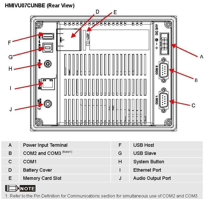
2 1.2 Features There are two types of features incorporated into the RAC: Status and Control. Below are lists of each: Status Type S1 & S2 Available S1 & S2 Connected S2 Connected Alarm Source 1 Data Information Source 2 Data Information Non-Auto Status Engine Test Status History of Alarm Control Type Go to Source 2 (Emergency) Go to Source 2 Abort Engine Test Engine Test Abort Silence Alarm Bypass TDNE/TDEN Manual Retransfer 1.3 Set-up and Wiring The RAC requires 24VDC power with a maximum current of 125 ma (See A below). There is a terminal block connector on the back of the unit to install wires for the power. The software comes preloaded onto the unit, and should require no user programming. Communication with the ATS controller is accomplished via Modbus RS-485. Drawing 66A8395 shows the wiring of the unit, which includes the power connection and the communication connector module. The cable used should have two insulated wires and one ground connected to the shield of the cable (see drawing 66A8395). The recommended cable is a CAT5E type but there are many similar shielded cables that can be used. The drawing also shows the connection between the two different controllers, the ATC-800 and the ATC There is a green LED on the back of the ATC-300+ that blinks when the unit is communicating. The communication connector inserts into the female side of the HMI COM2 port (see B below). The module has screw type terminal blocks to install the communication cable wiring. After the wires are installed, simply plug the adapter into COM2, and screw in both sides of the connector to the device. A picture of the adapter and a rear view of the unit are shown below. 2
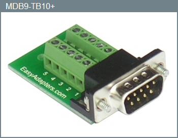
3 Communication Cable Adapter (connect to B below) 3

4 The setpoints on the ATC-300+ need to be set as follows for a single unit: Baud Rate: 9600 Address: 01 Terminated: On (termination micro-switch on back side of ATC-300+) There is a system menu on the HMI that allows the operator to change items like touch screen force, touch screen calibration, time & date, brightness & contrast, alarm and touch volume, and others. The HMI should be set up so the user will not have to adjust anything in the field. If a change is desired, there are two ways of accomplishing this: The first is to simply press the small SYSTEM button on the back of the unit for two seconds. The system menu will now be displayed on the screen. The menus are selfexplanatory but if help is required, one can download the manual from the Eaton website under HMiSoft User Manual effective February After the adjustments have been made, simply push the SYS button again for two seconds. Also see the instruction leaflet IL E that came with the display. The second option is to push the SETUP button and the new screen that appears will have a SYSTEM SETUP button. This is useful if the back of the unit is not easily accessible. This button will get the user in the same area as the SYSTEM button on the back of the unit. 1.4 Screens There are six screens that are displayed for the ATS functionality. Each screen has a return button to return to previous screen. If the unit is not communicating with the ATS (i.e., power is off at the ATS), the unit will display a red screen stating a communication error. Each of the screens and the associated buttons are described below. Screens: Top Level with S1 Connected 4

5 Top Level with S2 Connected, Alarm, and Non-Auto The top level screen shows the current status of the ATS. If the system switches to emergency (S2), an audible alarm will sound from the HMI. To silence the alarm, simply press the Silence Alarm button. The alarm flag will still be present, but the audio will be off. The volume of this alarm can be controlled in HMI system setup. To determine when S2 was connected and other alarms, press the Alarm Data button to display the next screen shown below. Data Screen The Data Screen shows the voltages and the frequency for each of the three phases. 5
 or S2 back to S1 (X).")
6 Alarm Data (Messages) The Alarm Data screen displays the S2 alarm history as well as other alarms shown below. The Alarm history displays an O or an X at the beginning to display when the unit was true or false; S2 connected (O) or S2 back to S1 (X). To clear the information, simply push the Clear History button. ALARM Messages 1. Overvoltage 2. Undervoltage 3. Over Frequency 4. Under Frequency 5. Plant Exerciser 6. Engine Test 7. Remote Engine Test 8. Voltage Unbalance 9. Phase Reversal 10. Go to Emergency 11. Lockout 12. Failed to Sync (phase angle) 13. Failed to Sync (frequency difference) 14. Engine Test or Plant Exercise 15. Source 1 Error 16. Source 2 Error 6

.")
7 Initial Setup Screen The initial setup screen allows the user to type in a name for the ATS controller. This name will be displayed throughout the HMI status screens, and is for aesthetic purposes only. The user can also disable the com link by pressing on the green circle. Password Table Pop-up Passwords are needed to get to the Engine Test and Go to Emergency (To S2) screens. These two screens are at security level two which is factory set to AC44. If you would like to change any of the passwords, navigate to the password table in the SETUP screen (you must input 0300 which is the level 3 password). If you change it, do not forget the level 3 password or you will be unable to edit passwords in the future. To enter the password table: 0300 To run an engine test: AC44 To transfer To S2: AC44 7

8 Engine Test By pressing Start Test, the controller will start the generator and then run the engine test when S2 is available. (Push the Silence Alarm button to remove the audio). To abort the test before the time is up, push the Abort Test button. One can use the Bypass TDNE/TDEN if desired. Transfer Control By pressing the Go To S2 button, the switch will transfer to source 2 if there is available power on S2. To go back to S1, push the Return to S1 button. One can use the Bypass TDNE/TDEN if desired. The Manual Retransfer button will appear if the controller has manual retransferring enabled. Pressing it will send the command to the ATC-300+ controller, but only if it is enabled. CAUTION This is a remote control device. Caution should be applied to make sure that appropriate procedures are in place for Engine Tests and To S2. Appropriate 8
9 procedures include, but are not limited to, switch doors being closed and latched, personnel knowledgeable of transfers, and other site safety recommended procedures. 9
1.1 Ethernet Remote Annunciator Controller (RAC) using the up to 4 ATC-300+ connected via RS-485 to TCP/IP gateway
 using the up to 4 ATC-300+ connected via RS-485 to TCP/IP gateway") Ethernet Remote Annunciator Controller (RAC) Instruction Sheet for Automatic Transfer Switches (4 x ATS) Revision: 01 IB01602082E 1.1 Ethernet Remote Annunciator Controller (RAC) using the up to 4 ATC-300+
Ethernet Remote Annunciator Controller (RAC) Instruction Sheet for Automatic Transfer Switches (4 x ATS) Revision: 01 IB01602082E 1.1 Ethernet Remote Annunciator Controller (RAC) using the up to 4 ATC-300+
1.1 Remote Annunciator Controller (RAC) and 1 Switch (ATC-600/800) via Modbus TCP/IP Ethernet Gateway
 and 1 Switch (ATC-600/800) via Modbus TCP/IP Ethernet Gateway") Remote Annunciator Controller (RAC) Instruction Sheet for Automatic Transfer Switches (ATS) Revision:01 IB01602088E 1.1 Remote Annunciator Controller (RAC) and 1 Switch (ATC-600/800) via Modbus TCP/IP
Remote Annunciator Controller (RAC) Instruction Sheet for Automatic Transfer Switches (ATS) Revision:01 IB01602088E 1.1 Remote Annunciator Controller (RAC) and 1 Switch (ATC-600/800) via Modbus TCP/IP
ModSync Sequencing System Installation & Operation Manual. For use with Fulton Steam Boilers.
 ModSync Sequencing System Installation & Operation Manual For use with Fulton Steam Boilers. Revision 3.0 8/21/2008 - 2 - Table of Contents Introduction Page 4 Features Page 4 Sequence of Operation Page
INSTALLATION INSTRUCTIONS
 TT-1343 5/06b INSTALLATION INSTRUCTIONS Original Issue Date: 8/03 Model: Automatic Transfer Switches Equipped with Series 1000 Programmable Controller Market: ATS Subject: Remote Annunciator Kits GM28938-KP1,
Med Touch Master Alarm
 Submittal Data Sheet Features The Powerex Med Touch Master Alarm Panel monitors and displays normal and alarm conditions from up to 128 remote medical gas source signals and provides alarm conditions as
Multiple Battery Cabinets Dual-Lite TRN. External Maintenance Switch Configuration Options. External Maintenance Switch Options
 Table 4 External Maintenance Switch Configuration Options External Maintenance Switch Options Installed with Interlock Option Option Auxiliary Contact Status open = On Test position or Maintenance position,
Tri-Tech Medical Inc.
 Submittal Data Sheet Project Information Project Number Approval Features The Tri-Tech Area and Master Alarm Panel digitally displays gas pressure (1 psi increments) monitors and displays normal and alarm
OPERATION / INSTALLATION
 OPERATION / INSTALLATION & PROGRAMMING MANUAL AFP-2800 LCD-80 Fire Alarm Panel Revision 1.01 November 16, 2004 NSW (Head Office) 7 Columbia Court Norwest Business Park Baulkham Hills NSW 2153 Ph: (02)
CONTROL PANEL INTERFACE ACTIVATE THE GENERATOR DISPLAY INTERFACE MENUS. Control Panel USING THE AUTO/OFF/MANUAL SWITCH
 CONTROL PANEL INTERFACE USING THE AUTO/OFF/MANUAL SWITCH With the switch set to AUTO, the engine may crank and start at any time without warning. Such automatic starting occurs when utility power source
Tri-Tech Medical Inc.
 Submittal Data Sheet Project Information Project Number Approval Features The Master Alarm Panel conversion kits are designed to upgrade or retro-fit existing panels produced by several major brands. The
Dryer Controller M720
 User Manual Dryer Controller M720 Hardware version 2.00 Software version 2.00 Manual M720 Dryer controller Page 1 of 60 Document history Preliminary version: - Created in April, 2009 Hardware Version 2.00,
User s Manual. TIGER S EYE E-Series Mark V Jockey. TIGERFLOW Systems, Inc Mint Way Dallas, Texas
 User s Manual TIGER S EYE E-Series Mark V Jockey TIGERFLOW Systems, Inc. 4034 Mint Way Dallas, Texas 75237 214-337-8780 www.tigerflow.com TABLE OF CONTENTS Introduction... 4 Sequence of Operation... 5
OVEN INDUSTRIES, INC.
 OVEN INDUSTRIES, INC. OPERATING MANUAL Model 5C7-252 TEMPERATURE CONTROLLER With PLC Inputs Introduction Thank you for purchasing our controller. The Model 5C7-252 is an exceptionally versatile unit and
Replaceable LED modules. Sleep or unattended mode. Auto-silence and auto-acknowledge
 Replaceable LED modules 11 Alarm Sequences as per ISA-18.1 standard Each channel/window fully field programmable RS232 or RS485 MODBUS-RTU communication Repeat relay for each window and multifunction relays
VT8000 Series Replacement Procedure to Replace VT8000 Series Room Controller and Pair with ZigBee Pro Sensors
 VT8000 Series Replacement Procedure to Replace VT8000 Series Room Controller and Pair with ZigBee Pro Sensors Overview 2 This procedure shows how to replace VT8000 Room Controllers already installed, as
Table of Contents 1. OVERVIEW SYSTEM LAYOUT SPECIFICATIONS FUNCTION... 11
 Table of Contents 1. OVERVIEW... 3 2. SYSTEM LAYOUT... 4 3. SPECIFICATIONS... 8 3.1 SYSTEM COMPONENTS...9 3.2 PLC INPUTS AND OUTPUTS...9 3.3 FUNCTION KEYS...10 3.4 DEFAULT SET POINTS AND TIMERS...10 4.
Adaptive CyCLO Technical and HMI User Guide. CyCLO User Guide. Version th December 2017 REV
 CyCLO User Guide Version 2.00 19 th December 2017 REV 2.00 1 Contents 1. Hardware... 3 1.1. Introduction... 3 1.2. Electrical Specification... 3 1.3. Board Overview... 4 1.4. Electrical Installation...
JADE Economizer with W7220-PCMOD Tool and Prestige IAQ 2.0 Thermostat
 JADE Economizer with W7220-PCMOD Tool and Prestige IAQ 2.0 Thermostat The JADE controller is a digital unit with economizing, demand control ventilation, and auto calibration strategies used to provide
CLEANROOM MONITOR CR3A Network - Installation Instructions
 CLEANROOM MONITOR CR3A Network - Installation Instructions INTRODUCTION The CR3 Series Cleanroom Monitor, was developed specifically to allow for monitoring of confined spaces with accuracy and reliability.
User s Guide CN616A. Universal 6 Channel ¼ DIN Process Controller. Shop online at omega.com
 TM User s Guide Shop online at omega.com e-mail: info@omega.com For latest product manuals: www.omegamanual.info CN616A Universal 6 Channel ¼ DIN Process Controller omega.com info@omega.com U.S.A. Headquarters:
Pioneer-R16 Gas Monitor Operator s Manual
 Pioneer-R16 Gas Monitor Operator s Manual Edition 7/2/97 RKI INSTRUMENTS, INC RKI Instruments, Inc. 33248 Central Ave, Union City, CA 94587 (510) 441-5656 Chapter 1: Description About the Pioneer-R16 Gas
La Marche Manufacturing Company Option 46 Series. Digital Combined Accessory Package. Installation and Operation Manual
 La Marche Manufacturing Company www.lamarchemfg.com Option 46 Series Digital Combined Accessory Package Installation and Operation Manual This manual is subject to change without notice. You may obtain
21-light Remote Annunciator. Owner s Manual
 21-light Remote Annunciator Owner s Manual Annunciator Description... Inside Font Cover Detailed Specifications... 1 Environmental Specifications... 1 Power Supply Requirements... 1 Communication With
User Manual Doc.Ref : JA-KNX-UM. JA-KNX Jablotron KNX Interface ELAUSYS JA-KNX. KNX Interface for Jablotron alarm system.
 Page : 1 of 17. ELAUSYS JA-KNX KNX Interface for Jablotron alarm system User Manual Document history Version. Date Author Comment 1.00 24-JUN-2017 NDE First issue 1.01 14-NOV-2017 NDE Support for user
LD5100 USER GUIDE RLE TECHNOLOGIES
 LD5100 USER GUIDE RLE TECHNOLOGIES 2007 RLE Technologies 110043 Rev 0.1 (09/2007) LD5100 2007 RLE Technologies 110043 Rev 0.1 (09/2007) LD5100 User Guide: LD5100 Table of Contents TABLE OF CONTENTS Chapter
Toxic and Explosive Smart Gas Monitor PN / Installation and User Manual
 Toxic and Explosive Smart Gas Monitor PN 151022/151023 Installation and User Manual Quest Controls, Inc. 208 9 th Street Dr. West Palmetto, FL 34221 www.questcontrols.com Phone: (941) 729-4799 Fax: (941)
Project: Customer: Engineer: Pump Manufacturer: Model GPY + GPU. with Automatic Power Transfer Switch
 Project: Customer: Engineer: Pump Manufacturer: Model GPY + GPU with Automatic Power Transfer Switch Contents: NOTE: The drawings included in this package are for controllers covered under our standard
Model VPS Pressure Limiting (VFD) Electric Fire Pump Controller with Soft Start Bypass
 Electric Fire Pump Controller with Soft Start Bypass") Project: Customer: Engineer: Pump Manufacturer: Submittal Document Model VPS Pressure Limiting (VFD) with Soft Start Bypass Contents: Data Sheets Dimensional Data Wiring Schematics Field Connections Note:
Project: Customer: Engineer: Pump Manufacturer: Submittal Document Model VPS Pressure Limiting (VFD) with Soft Start Bypass Contents: Data Sheets Dimensional Data Wiring Schematics Field Connections Note:
Analog Room Pressure Monitor RPC Series
 Description The Room Pressure Monitor is used to measure differential pressure in the range of 0.125 to 1"wc or 30 to 250 Pa. It combines precision high sensitivity silicon sensing capabilities and the
Med Touch Combination Alarm Conversion Kits
 Submittal Data Sheet Features The Powerex Combination Alarm Panel conversion kits are designed to upgrade or retro-fit existing panels produced by several major brands. The conversion kit replaces all
GLD-30 Gas Leak Detector
 GLD-30 Gas Leak Detector Installation, Operation & Maintenance General: The Archer Instruments GLD-30 is an ambient air monitor, used to detect the presence of a target gas (or gases) and to alert operators
Section 5. Control Systems
 Section 5 There are several Kaleidescape options available for controlling a Premier system. Kaleidescape Remote Kaleidescape App for ipad Kaleidescape Child Remote Browser interface control panels A Premiere
Technical Data Submittal Document
 Project: Customer: Engineer: Pump Manufacturer: Technical Data Submittal Document Model GPL + GLU Limted Service Full Voltage Across the Line Start Electric Fire Pump Controller Contents: Data Sheets Dimensional
Installation and Operation Manual
 SENTRY Protect Plus QUADPLEX PANEL Installation and Operation Manual For Hardwired Pumps Environment e Corporation Table of Contents 1 Overview...3 2 Sentry Protect Plus Quadplex Menu Flowchart...4 3 Wiring
RS485 MODBUS Module 8AI
 Version 1.4 15/04/2013 Manufactured for Thank you for choosing our product. This manual will help you with proper support and proper operation of the device. The information contained in this manual have
AGC 200 Advanced Gen-set Controller OPERATOR S MANUAL
 Advanced Gen-set Controller OPERATOR S MANUAL Display readings Push-button functions Alarm handling Log list Document no.: 4189340607A SW version 3.5X.X or later Table of contents 1. ABOUT THIS DOCUMENT...3
Instruction Bulletin
 Instruction Bulletin 435-54-26A 9/99 Monroe, NC, USA MODEL 98 Digital Temperature Controller For Medium Voltage Transformers Class 3, 4 Retain for future use. NOTICE Read these instructions carefully and
725B Configuration Software Manual
 725B Configuration Software Manual REV DATED DESCRIPTION AUTHOR APPROVED 0 09-03-10 First Issue P.Cartmell Page 1 of 80 SECTION 1 - SOFTWARE INSTALLATION... 5 725B ConfigurationSoftware Installation...
Operating & Maintenance Manual. Alert-4 Ethernet LCD Master Alarm
 Operating & Maintenance Manual Alert-4 Ethernet LCD Master Alarm w w w. a m i c o. c o m Contents User Responsibility 4 Introduction 4 Features 5 Description of the Alarm 5 Shipment Details 5 The Alarm
Instruction manual MTL process alarm equipment. October 2016 CSM 725B rev 2 MTL RTK 725B. Configuration Software Manual
 Instruction manual MTL process alarm equipment October 2016 CSM 725B rev 2 MTL RTK 725B Configuration Software Manual SECTION 1 - INTRODUCTION... 5 Basic Requirements... 5 SECTION 2 - SOFTWARE INSTALLATION...
Series DCT1000DC Dust Collector Timer Controller Specifications Installation and Operating Instructions
 Series DCT1000DC Dust Collector Timer Controller Specifications Installation and Operating Instructions Bulletin E-97DC Thank you for purchasing the Dwyer DCT1000DC Dust Collector Timer Controller. You
The Kryos LN2 Liquid Level Control & Cryogenic Temperature Control
 The Kryos LN2 Liquid Level Control & Cryogenic Temperature Control Created for Taylor-Wharton Gas Equipment By Pacer Digital Systems, Inc. INTRODUCTION... 4 TEXT FORMAT NOTATION... 4 SYSTEM COMPONENTS...
Drawing Submittal Package
 Project: Customer: Engineer: Pump Manufacturer: Drawing Submittal Package Model GPL + GLU Limited Service Full Voltage Across the Line Start Electric Pump Controller with Automatic Power Transfer Switch
Model VPS + VPU Pressure Limiting (VFD) Electric Fire Pump Controller with Soft Start Bypass with Automatic Power Transfer Switch
 Electric Fire Pump Controller with Soft Start Bypass with Automatic Power Transfer Switch") Project: Customer: Engineer: Pump Manufacturer: Technical Data Submittal Document Model VPS + VPU Pressure Limiting (VFD) with Soft Start Bypass with Automatic Transfer Switch Contents: Data Sheets Dimensional
Project: Customer: Engineer: Pump Manufacturer: Technical Data Submittal Document Model VPS + VPU Pressure Limiting (VFD) with Soft Start Bypass with Automatic Transfer Switch Contents: Data Sheets Dimensional
User Manual. Dryer Controller M720
 User Manual Dryer Controller M720 Hardware version 1.00 Software version 1.00 Preliminary version Manual M720 Dryer controller Page 1 of 42 Document history Preliminary version: - Created in April, 2009
RTD TEMPERATURE SENSING SYSTEM
 General Overview RTD TEMPERATURE SENSING SYSTEM The Prime Technology RTD Temperature System 9219-00-0002 is a three-channel temperature measuring system that utilizes two RTD Temperature Sensor inputs
USER MANUAL FOR OPERATING SYSTEM
 P2262 ALARM PANEL USER MANUAL FOR OPERATING SYSTEM 21765-07 September 1999 Associated Controls (Aust) PTY. LTD. 29 Smith Street, Hillsdale, NSW, 2036. PH (02) 9311 3255, FAX (02) 9311 3779 Page 1 of 177
Operation Manual Fighter ProVision Software. Version: 0.0 Revision: 1
 Operation Manual Fighter ProVision Software Version: 0.0 Revision: 1 TABLE OF CONTENTS 1. Introduction 5 2. Software Installation 5 3. PC Users 6 3.1 Introduction 6 3.2 Default Code 6 3.3 Edit PC User
ANNUNCIATOR FIXED MODULE
 12 Clintonville Road Northford, CT 06472 Phone: 203-484-7161 Fax: 203-484-7118 THE ANNUNCIATOR FIXED MODULE Installation Manual for the AFM-16ATF and AFM-32AF Annunciator Modules Document # 15970 3/27/95
PRODUCT BULLETIN. Rev. A Monitoring Station offering PN Rev. B as a direct replacement. OVERVIEW / DESCRIPTION
 PRODUCT BULLETIN ISSUE/DATE: March 28, 2008 rev A BULLETIN NUMBER: AQ032808 SUBJECT: Monitoring Station PRODUCT LINE: Aquafine UV Equipment TOPIC: REVISION TO THE 41114-1 MONITORING STATION OVERVIEW /
IntesisBox BACnet/IP Server - Notifier ID3000 series
 IntesisBox Server - Notifier ID3000 series Gateway for integration of Notifier ID3000, ID3002, ID50 and ID60 fire panels into enabled control systems. Integrate your Notifier fire panels into your BACnet
FI6000 INSTRUCTION MANUAL. Thank you for choosing another quality product from Amperes Electronics. Fire Alarm Interface
 INSTRUCTION MANUAL FI6000 Fire Alarm Interface Thank you for choosing another quality product from Amperes Electronics. FI6000 is a phase evacuation controller which can be integrated with various Amperes
Compod. Instruction Manual IM-COMPOD Revision: F, December 2015
 Compod Programmable Control Module For 100 Series Digital Mass Flow Meters & Controllers Instruction Manual IM-COMPOD Revision: F, December 2015 CORPORATE HEADQUARTERS 5 Harris Court, Building L, Monterey,
Installation and Maintenance Manual IM
 Installation and Maintenance Manual IM 1234-1 BACnet Thermostat Group: Applied Air Systems Part Number: IM 1234 Date: December 2014 Use with Daikin MicroTech Integrated Systems or as standalone Table of
Addendum HART Communication with the X2200 UV Flame Detector 1.1 4/
 Addendum HART Communication with the X2200 UV Flame Detector 1.1 4/09 Table Of Contents Interconnecting the HART Communicator with the Detector.... 1 HART Device Description Language.... 3 Detector Wiring.......................................
SCAN200E USER S MANUAL
 SCAN200E USER S MANUAL Code No. 2071 1052 rev. 1.4 Code No. 2071 1052 Rev. 1.4 Page 2/16 SCAN200E User s Manual Foreword This manual is for SCAN200E Controller running software version 2.03 or later. We
Emerson Inspire 1HDEZ Installation Instructions. Thermostat/Interface Equipment Control TROUBLESHOOTING
 Emerson Inspire 1HDEZ-1521 Installation Instructions Thermostat/Interface Equipment Control TROUBLESHOOTING FAILURE TO READ AND FOLLOW ALL INSTRUCTIONS CAREFULLY BEFORE INSTALLING OR OPERATING THIS CONTROL
The Protec driver connects to the Protec Fire Detection range of digital addressable fire control panels. Available for Commander and ObSys.
 The Protec Driver The Protec driver connects to the Protec Fire Detection range of digital addressable fire control panels. Available for Commander and ObSys. This document relates to Protec driver version
Two-Channel Gas Controller
 Two-Channel Gas Controller Specifications subject to change without notice. USA 09 Page of DESCRIPTION Highly configurable, UL 0 performance-tested and -certified, and wall-mounted gas monitor; continuously
Digital Marine Exhaust Temperature Alarm
 Digital Marine Exhaust Temperature Alarm Model: SM007D/S INTRODUCTION COMPONENTS Marine water cooled exhaust systems are designed to withstand temperatures of up to about 120 C. However the exhaust gases
Liebert LDMF Distribution Monitoring. User Manual
 Liebert LDMF Distribution Monitoring User Manual TABLE OF CONTENTS IMPORTANT SAFETY INSTRUCTIONS................................................1 1.0 GLOSSARY OF ABBREVIATIONS.............................................2
User Manual Doc.Ref : EVO-KNX-UM. EVO-KNX Paradox KNX Interface ELAUSYS EVO-KNX. KNX Interface for Paradox alarm system. User Manual.
 Page : 1 of 17. ELAUSYS EVO-KNX KNX Interface for Paradox alarm system User Manual Document history Version. Date Author Comment 1.00 14-AUG-2017 NDE First issue Page : 2 of 17 TABLE OF CONTENT 1. INTRODUCTION
ROYCE SUSPENDED SOLIDS SYSTEM MODEL 7011A AND SENSORS MODELS 72A, 72P, 73B, 74A, 75A & 76A
 SPECIFICATIONS (Revised 1/12/2006) ROYCE SUSPENDED SOLIDS SYSTEM MODEL 7011A AND SENSORS MODELS 72A, 72P, 73B, 74A, 75A & 76A The system shall operate on the principle of light absorption. It shall consist
Remote Display Alarm Indicator for Oxygen monitor
 Remote Display Alarm Indicator for Oxygen monitor (Part number 99091) The Remote Display Alarm Indicator is designed to display remote oxygen concentration information from PureAire oxygen monitors. All
RF SCOUT PLUS INSTRUCTION MANUAL. Dielectric, LLC 22 Tower Rd. Raymond, ME Phone: January 2015, Rev B 1
 RF SCOUT PLUS INSTRUCTION MANUAL Dielectric, LLC 22 Tower Rd. Raymond, ME 04071 Phone: 800.341.9678 www.dielectric.com 21 January 2015, Rev B 1 WARNING Powering RF sensors above +30dBm (1W) will cause
A36D/TPSD Modbus TCP SCADA INTERFACE INSTRUCTIONS
 SCADA INTERFACE INSTRUCTIONS - OPTION 21Q - FOR A36D/TPSD SYSTEMS with 500 and 550 option. A36D/TPSD Modbus TCP SCADA INTERFACE OPTION 21Q INSTRUCTIONS This manual is valid for A36D/TPSD Chargers equipped
Conventional Releasing Control Panel
 s Data Sheet Fire Safety Products Conventional Releasing Control Panel Pre-Action Deluge Agent-Releasing Fire System Model TXR-320 Remote configurable Up to two (2) hazard areas Operable with the following:
Modbus RTU RS485 Manual
 Modbus RTU RS485 Manual AUTOMATED FUEL MAINTENANCE SYSTEMS FTI-5A, FTI-10A, FTI-20A FUEL TECHNOLOGIES INTERNATIONAL 06/10/2014 Rev B - Fuel Technologies - Modbus The Modbus Communications Setup Button
Halton SAFE / 7.14 user guide and installation instructions
 Halton SAFE / 7.14 user guide and installation instructions VERIFIED SOLUTIONS BY H A LTO N Enabling Wellbeing Table of contents 1 System description 3 2 User Accounts 4 3 Main menu 7 3.1 Main menu - Change
FieldServer Driver - Serial FS Notifier NCA
 Driver Version: 1.00 Document Revision: 15 Description FieldServer Driver - Serial FS-8700-98 Notifier NCA The NCA (Network Control Annunciator) Serial driver allows the FieldServer to record data from
RCS Residential Control Systems Inc.
 RCS Residential Control Systems Inc. Model TZ16 Z-Wave Communicating Thermostat with Rev P HVAC Control Unit INSTALLATION AND OPERATION MANUAL DCN: 141-00882 Rev 02 5/18/06 This manual applies to the following
Lyric Gateway. User Reference Guide. Ref: LCP300-L/LCP300-LC /16 Rev A
 Lyric Gateway User Reference Guide Ref: LCP300-L/LCP300-LC 800-21670 10/16 Rev A Your Honeywell security system is designed for use with devices manufactured or approved by Honeywell for use with your
D8024, D9024, D10024 Analog Fire Alarm Control Panels Programming Guide
 System Reset Trou ble Silence Ala rm Silence Manual Ala rm ENTER NO YES Letters Numb ers Keyword Radionics System Reset Trouble Silence Alarm Silence Manual Alarm ENTER NO YES Le ters Numbers Keyw ord
RION ORION TELECOM NETWORKS INC. E2, 2Mbps x 4 Opti-Multiplexer Integrated E2, OLTE and Multiplexer. Product Brochure & Data Sheet TELECOM NETWORKS
 RION TELECOM NETWORKS ORION TELECOM NETWORKS INC. E2, 2Mbps x 4 Opti-Multiplexer Integrated E2, OLTE and Multiplexer Product Brochure & Data Sheet Headquarters: Phoenix, Arizona 20100, N 51st Ave, Suite
Instruction Manual December 2001 ENACOCU02
 SENACOCU02 Instruction Manual December 2001 ENACOCU02 Safety Guidelines Warning notices must be observed to ensure personal safety as well as that of others, and to protect the product and the connected
LEAKMONITOR MULTIZONE WATER LEAK DETECTION ALARM PANEL INSTALLATION AND USER OPERATION MANUAL
 LEAKMONITOR MULTIZONE WATER LEAK DETECTION ALARM PANEL INSTALLATION AND USER OPERATION MANUAL The LeakMonitor alarm panel is a microprocessor controlled fully adjustable alarm system suitable for multizone
Service Manual Models: 1.0, 1.3, and 1.5
 AWX2-SER_100160837_2000000360_Rev F Service Manual Models: 1.0, 1.3, and 1.5 LOW LEAD CONTENT WARNING This manual must only be used by a qualified heating installer / service technician. Read all instructions,
Installation Manual. ATS Remote Annunciator Catalog 5310 DANGER WARNING A
 ASCO 530 Installation Manual Installation Manual The ASCO 530 ATS Remote Annunciator is listed under the Underwriter s Laboratories Standard UL-008 for Automatic Transfer Switch accessories. This stand-alone
EOS INTERFACE GUIDE AND POINTS LIST For EOS BTCII Firmware Version J1239D-570 and newer
 Installation and interface must be performed by a qualified controls technician. IMPORTANT: THIS MANUAL CONTAINS INFORMATION REQUIRED FOR INSTALLATION, INTERFACE AND CONFIGURATION OF THIS EQUIPMENT. READ
Metasys Integrator Airflow Application
 Metasys Connectivity Technical Manual 69. Metasys Integrator Section Application Note Issue Date 0998 APPLICATION NOTE Metasys Integrator Airflow Application lntroduction Page Application Details * Component
TSI Model 8630 PRESSURA Room Pressure Monitor Modbus Communications Application Note LC-106
 Critical Environments TSI Model 8630 PRESSURA Room Pressure Monitor Modbus Communications Application Note LC-106 Modbus communications are installed in all Model 8630 hospital room pressure controllers
Quick-Start Guide Digi-Sense TC9000 Advanced PID and On/Off Temperature Controller with Thermocouple Input Models and
 Quick-Start Guide Digi-Sense TC9000 Advanced PID and On/Off Temperature Controller with Thermocouple Input THE STANDARD IN PRECISION MEASUREMENT 1 Getting Started: 7 6 2 1 Front 5 4 3 1) RUN/STOP Button
*IG1583EW* Aurora Touch UPC Kit Instruction Guide. Aurora Touch UPC Kit Instruction Guide
 Aurora Touch UPC Kit Instruction Guide For use in single compressor water-to-air equipment utilizing fi rmware UPCSWASTD01-01 Aurora Touch UPC Kit Instruction Guide *IG1583EW* IG1583EW 08/14 Aurora Touch
Weekly Testing of Dedicated Smoke Control Dampers - Metasys System Extended Architecture
 Weekly Testing of Dedicated Smoke Control Dampers - Metasys System Extended Architecture Code No. LIT-1201743 Release 1.2 Issued Date July 30, 2004 Supersedes Document Introduction.................................................
Micro-VPAC IIT LSC - Lift Station Controller. User Manual. Version 1.0.2
 Micro-VPAC IIT LSC Micro-VPAC IIT LSC - Lift Station Controller User Manual Version 1.0.2 Table of Contents ii CHAPTER: Table of Contents Contents Introduction 5 General 6 Control Description 6 Manual
SAFETY CERTIFIED MODEL FP-700 COMBUSTIBLE GAS DETECTOR
 SAFETY MANUAL SIL 2 Certified Model FP-700 Combustible Hydrocarbon Gas Sensor Version 2.0 1 SAFETY CERTIFIED MODEL FP-700 COMBUSTIBLE GAS DETECTOR This manual addresses the specific requirements and recommendations
Weekly Testing of Dedicated Stairwell Pressurization Fans- Metasys System Extended Architecture Code No. LIT
 Weekly Testing of Dedicated Stairwell Pressurization Fans- Metasys System Extended Architecture Code No. LIT-1201739 Release 1.2 Issued Date July 30, 2004 Supersedes Document Introduction.................................................
TE809-Ats Instructions Manual
 TE809-Ats Instructions Manual Project: v2.0 PREFACE Thanking you for preference, TECNOELETTRA SRL hopes that the use of this equipment could be a reason of satisfaction. This manual is designed to put
APPLICATION DATA SHEET
 APPLICATION DATA SHEET Control Systems Transmitters Sensors Accessories Wall, 19 Rack or Panel Mounting Units 110/230V 50/60Hz AC operation 250 Addressable devices as: Relays, 4-20 Inputs or Gas Detectors
SCC Inc. Master Panel. Specifications. Document No. TS 2010 February 11, Product Description. Sample Specification
 February 11, 2019 Master Panel Product Description The Master Panel shall provide lead/lag control and time based, automatic rotation of up to eight (8) boilers, when used in conjunction with LMV3 or LMV5
TYPE CM-2201 NELSON SINGLE POINT CIRCUIT MANAGEMENT SYSTEM
 2 Line, 16 Characters/row LCD Display Temperature Input Range -50 C to +500 C -58 F to + 932 F Enclosure NEMA Type 4X Current Rating 30A max (resistive load only) Ambient Temperature -40 C to + 40 C -40
CT224 Setup Tutorial
 CT224 Setup Tutorial Table of Contents 1. Introduction 2. Configuring Controller for Operation A. Example 1 Over Temp Operation with Hysteresis @ 5º F. B. Example 2 Under Temp Operation with Hysteresis
FT40 Reduced Voltage - Part Winding. Electrically and Mechanically
 LMR PLUS Electric Fire Pump Controllers with Transfer Switch Features FT40 Reduced Voltage - Part Winding 1-1 January 2012 Product Description The Automatic Transfer Switch Option may be added to any FD
Drawing Submittal Package
 Project: Customer: Engineer: Pump Manufacturer: Drawing Submittal Package Model GPL + GLU Limited Service Full Voltage Across the Line Start Electric Pump Controller with Automatic Power Transfer Switch
Sequence of operation
 Sequence of operation IPS 4000 secondary variable speed control File No: 90.96 Date: february 21, 2013 Supersedes: new Date: new sequence of operation ips 4000 2 list of abbreviations: adj: Field Adjustable
Control manual. Series. Gas-fired direct vent Cast iron boilers. Control adjustment and Operation instructions
 KNCT2-808 KN Series Gas-fired direct vent Cast iron boilers Models KN-6, -10, -20 only (HeatNet control firmware edition 45 ) Control manual Control adjustment and Operation instructions Also read and
Addendum. HART Communication with the FlexSonic Acoustic Detector. 1.1 Rev: 1/
 Addendum HART Communication with the FlexSonic Acoustic Detector 1.1 Rev: 1/15 Table Of Contents Interconnecting the HART Communicator with the Acoustic Detector... 1 HART Device Description Language...
System Accessories, LCD Annunciators
 System Accessories, LCD Annunciators UL, ULC Approved* A4606 Series Color Touchscreen LCD Annunciators for 4007ES Fire Alarm Control Panels Features Fig 1: A4606-9202 LCD Annunciator with Red Trim Fig
LifeAlarm Fire Alarm Control Panels
 LifeAlarm Fire Alarm Control Panels UL, ULC Approved* Features Control panel operator convenience features: Wide viewing angle 2 x 20 (40 character) alphanumeric LCD and dedicated LEDs provide convenient
Operating Instructions READ AND SAVE THESE INSTRUCTIONS
 Operating Instructions READ AND SAVE THESE INSTRUCTIONS Aprilaire Communicating Thermostat Model 8870 CAUTION: Do not set to OFF mode during periods when freezing temperatures could occur. Thank you for