INSTALLATION MANUAL.
|
|
|
- Tracy Green
- 5 years ago
- Views:
Transcription


1 INSTALLATION MANUAL
2 FC200 - FC200/S - FC200/SL : Hereby, Bentel Security, declares that the above mentioned Control Panels are in compliance with the essential requirements and other relevant provisions of Directive 1999/5/EC.. The complete R&TTE Declaration of Conformity for each Panel can be found at These Control Panels comply with EN54-2; EN Installation of these systems must be carried out strictly in accordance with the instructions described in this manual, and in compliance with the local laws and bylaws in force. The above mentioned Control panels have been designed and made to the highest standards of quality and performance. The manufacturer recommends that the installed system should be completely tested at least once a month. BENTEL SECURITY Srl shall not assume the responsibility for damage arising from improper application or use. The above mentioned Control panels have no user-friendly components, therefore, should be serviced by authorized personnel only.. The FireClass200 is available in the following models: FC200 - Master panel with 4 A Linear power supply; FC200/S - Master panel with 2.5 A Switching power supply; FC200/SL - Slave panel without power supply unit. In this manual the name FireClass200 has been used to identify the control panel features that are common to all three models. However, the model has been specified when a feature applies to one model only. Proper functioning of the FireClass200 components can only be guaranteed when ambient conditions, external to the cabinet, comply with the 3k5 category of the IEC :1978. The Loops of the FireClass200 control panel can support up to 396 Analogue Devices. The Conventional Zone of the FireClass200 control panel can support up to 30 Conventional Devices. However, do not connect more than 512 devices to the FireClass200 control panel.. The FC200/SL Slave panel must have the BENTEL BA424 (27.6 V - 4 A) Linear power supply or the BENTEL BAQ60/24 (27.6 V A) Switching power supply, otherwise, the IMQ Certification will be forfeited. The FC200/SL Slave panel power supply must be installed by personnel with Access Level no.4 (see "Access Levels" paragraph). The FC200/SL Slave panel can function only when connected to a FireClass200 Master panel.. BENTEL SECURITY srl reserves the right to change the technical features of this product without prior notice. C.da Ravigliano - Z.I. S.Scolastica CORROPOLI (TE) - ITALY Installation manual: Analogue Fire Control Panel FireClass200 Istruzioni Inst. Inglese Antin. FC200/UK ISTINSFC200/UK
3 TABLE OF CONTENTS OVERVIEW 7 Access Levels Features Options with requirements Telecom Module FC200/COM (Optional) Alarm cycle PARTS IDENTIFICATION 11 Main unit (FireClass200) Output Expander (FC200/6OUT) Loop Interface Telecom Module FC200/COM Repeater INSTALLATION 21 Mounting Output expander Installation Telecom module installation FC200/COM Repeater Installation Connections Main board terminals Connection of Addressable Analogue Devices Connection of Conventional Devices Connection of Repeaters and Slave Panels Connection of Output Devices Bell Outputs Connection of Telecom Module FC200/COM Power Connection Maintenance CONTROL PANEL MANAGEMENT 35 General rules for management from panel Access to FireClass200 Management
4 PROGRAMMING 39 Auto (Autolearning) Connections: Loop 1 and Loop Connections: Network Programming: Fire sensors Programming: Monitoring modules Programming: Control modules Programming: Conventional Zone module Programming: Repeaters and Slave panels Devices Loop 1 and Loop Conventional Line Bell Outputs Network Password (PassWD) Welcome Message (MesINI) Zones OPTION Prealarm time Warning Threshold Alarm Verify Drift Compensation Timer and Special timer Delay Pulse Extinction Modes System Date and Time Blink Wires Silence mode Walk Test Network Printer Verify Factory Restore default Analogue Fire Control Panel FireClass200
5 Maintenance Telephone Dial. (Telephone Dialler) Commun. (Digital Telephone Communicator) T.Num (Telephone Numbers) Options Remote management MODIFYING 81 Disable Delete Verify Delete logger Telecom Module READING PARAMETER 87 Devices/Zones/Outputs Options Version Logger Logger data Print Telecom Module QUICK GUIDE 95 General features Terminals
6 6 Analogue Fire Control Panel FireClass200
7 OVERVIEW Access Levels FireClass200 has several access levels for control panel management. Level 1 Level 2A Level 2B Level 3A Level 3B Level 4 The Plexiglas window allows all persons to view the control panel status. The door-lock protects the manual commands (RESET, SILENCE and LOGGER), and allows access to authorized key holders only. Only User PINs (code of 1 to 5 digits) can Disable the Loop devices, Bell Outputs, Software Zones and Network devices. Only the Installer PIN (code of 1 to 5 digits) can access the programming phase of the control panel parameters. Access to the internal components of the control panel, for maintenance purposes ---- battery and fuse replacement etc., must be done by authorized persons only, and requires removal of the screws and upper door. Repairs to the electronic board (e.g. to substitute the EPROM memory) must be done by the manufacturer. Features Day/Night The FireClass200 control panel provides Day mode and Night mode. The Alarm Threshold and Warning Threshold can be increased by the programmed value, during programmed hours. In this way false alarms, caused by the persons present in the protected ambient, will be reduced considerably. DAY Mode ----Silence will be enabled until the SILENCE button is pressed again. NIGHT Mode ----Silence will be enabled for the programmed time (from 0.5 to 30 minutes). The change-over from DAY to NIGHT Mode can be done manually, by means of the Silence option from the SYSTEM menu or automatically, as per the programming of the two Timers (it is possible to program the precise hours and days of the week when the control panel must operate in DAY Mode). OVERVIEW 7
8 Options with requirements The FireClass200 control panel performs the following options with requirements (complies with European norm EN54 part 2): outputs to fire alarm routing equipment co-incidence detection fault signals from points disablement of addressable points Test condition Telecom Module FC200/COM (Optional) The Telecom Module can call and send recorded messages to the programmed telephone numbers and, by means of communication protocols, can also send data to central stations. This module allows system management ---- through the FC200/SW software package installed on the PC that is connected to the telephone line. Description 8 independent channels Records one 11 second alarm message for each channel 32 programmable telephone numbers (modifiable) Up to 15 digits per telephone number; allows pauses of 1 or 5 seconds Repeats alarm messages for 20, 40, 60 or 80 seconds Repeats call cycle up to 5 times Voice answer detection Bypassable "dial tone" test Electronic telephone line interface Over-voltage protection DTMF and Pulse dialling Digital recording / Message play Non-volatile memory for data storage Manages the following communication protocols: ADEMCO SLOW 10 BAUD, ADEMCO FAST 14 BAUD, FRANKLIN 20 BAUD, RADIONICS 40 BAUD, SCANTRONIC 10 BAUD, CONTACT ID (DTMF), SIA 300 BAUD. Alarm cycle In the event of an alarm status on an alarm channel, the telephone dialler will generate the alarm cycle, shown in figure 1. 8 Analogue Fire Control Panel FireClass200
9 Phase 1 Phase 2 Phase 3 The telephone dialler will switch the telephone line. After 3 seconds the dialler will engage the telephone line. If the Dial-tone check option is enabled (refer to "Programming" chapter) the dialler will check for the dial tone, and when detected, will step to successive phase. If the dial tone is not detected (option enabled) the dialler will hook-up and step back to phase1. The Dial-tone check will be done 4 times, after which the dialler will step to the successive telephone number. If this option is disabled the dialler will step directly to the successive phase. Phase 4 Phase 5 Phase 6 Call cycle The dialler will dial the telephone number of the alarm channel in alarm status. If the Voice answer detection option is enabled (refer to "Programming" chapter), the dialler will wait 25 seconds for a voice answer and, when voice answer is detected, the dialler will step to the successive phase. However, if the Voice answer detection option 6 is disabled, the dialler will pause for a few seconds before stepping to the successive phase. The dialler will send the alarm message assigned to the alarm channel in question. The message will be played for the programmed Message playback time (20, 40, 60 or 80 seconds). The Call cycle (set during programming) determines the number of times that each telephone number ---- assigned to the alarm channel in alarm status will be called (1 to 5 times). Figure 1 Telecom Module alarm cycle. OVERVIEW 9
10 10 Analogue Fire Control Panel FireClass200
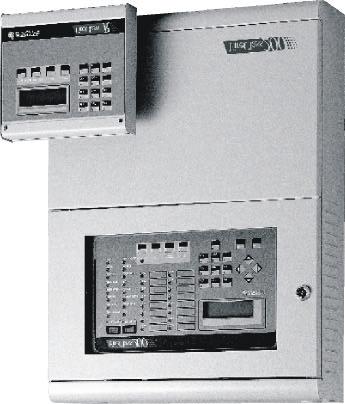
11 PARTS IDENTIFICATION This chapter holds the full description of the main components and LEDs of the FireClass200. In most cases, the numbers in boldface refer to the parts shown in the tables and figures. Main unit (FireClass200) The Flashing status of certain LEDs is not dealt with in the following table, as it signals that the assigned event occurred and ended before the last rearming operation. LED MEANING ALARM ON: the control panel is in ALARM status. MORE ALARMS ON: presence of more than one alarm condition. PRE-ALARM FLASHING: PRE-ALARM status - the sensors have detected an alarm condition. The Outputs will be activated when the PRE-ALARM delay ends. TELECOM ON: the control panel is physically connected to the telephone line. MAIN POWER WALK TEST OFF: mains failure. Mains power must be restored before the batteries empty. FLASHING: Walk Test mode on a Software Zone; an alarm condition on the Zone in question will generate an alarm status on the assigned Outputs for approximately one second. DISABLED ON: at least one device is disabled. NIGHT ON: the control panel is operating in NIGHT mode. DAY ON: the control panel is operating in DAY mode. FAULT MAINS LOW BATTERY ON: presence of at least one fault condition; the type of fault will be signalled by the associated LED and/or on the display. ON: mains failure; the standby batteries will takeover the power supply to the control panel. This LED is complementary to the green MAINS- POWER LED, and will continue to signal the fault event after mains power has been restored (memory). ON: low batteries; proper functioning of the control panel cannot be guaranteed in the event of black-out. Wait several hours, if the LED stays ON the batteries are not rechargeable and must be replaced BATTERY FAULT ON: batteries are completely empty or not connected - check fuse 41 GROUND ON: voltage leak to ground - check connection insulation. FUSES ON: burnt fuse (fuse 41 or 42) - the fuse concerned will be indicated on the display. LOGIC UNIT ON: "blocked" microprocessor - call Installer for service. PARTS IDENTIFICATION 11
12 ADDRESS ON: loss of a loop device. SAME ADDRESS ON: two devices on the same loop have the same address. SILENCE Z01 Z16 ON: the SILENCE button has been used to places the SILENCEABLE Outputs in standby status. DAY mode SILENCE status will be held until the SILENCE button is pressed again. NIGHT mode SILENCE will be held for the programmed SILENCE time. ON: the corresponding zone is in ALARM Status. Flashing (3 secs. ON - 1 sec. OFF): the corresponding Zone is in PRE- ALARM status. Flashing (1 sec. ON sec. OFF): the FIXED delay is active. Flashing (2 secs ON - 2 secs OFF): the PAS delay is active. BUTTON FUNCTION SILENCE Places the SILENCEABLE Outputs in standby status: DAY mode SILENCE status will be held until the SILENCE button is pressed again. NIGHT mode SILENCE is held for the programmed SILENCE time. ACK Activates the PAS delay (if pressed when the FIXED delay is active). RESET REARMS the control panel. TEST Tests the control panel buzzer and LEDs. When this button is pressed, all warning LEDs should light and the buzzer should emit a intermittent acoustic signal (1 sec. beep - 1 sec. pause). PART DESCRIPTION 1 Control panel door with Plexiglas window 2 Pocket for zone description 3 LCD 4 rows columns 4 Command panel 5 Control panel door lock 6 Two screws for securing command panel and battery compartment door 7 Battery compartment door stop 8 Battery compartment door 12 Analogue Fire Control Panel FireClass200
13 Figure 2 Main unit parts (external) PARTS IDENTIFICATION 13
14 PART 9 DESCRIPTION Jumper to enable programming: > programming enabled (default) > programming disabled 10 Keypad/Display board 11 Cable passage (3 x 30 mm) 12 Wall mounting holes (4 x 5 mm) 13 6 Output expander FC200/6OUT (optional - 2 maximum) 14 Telecom module FC200/COM (optional) 15 Main board V - 4 A linear power supply/battery charger V A switching power supply/battery charger 18 Battery connectors 19 Compartment for two (optional)12 V, 17 Ah batteries 20 Jumper for series connection of batteries 21 Bag holding: two F 250V 3.15A fuses; one F 250V 6.3A fuse; two keys; four 1N4007 diodes; jumper for series connection of batteries 22 Chased cable passage (40 x 170 mm) 23 Loop interface 14 Analogue Fire Control Panel FireClass200
15 Figure 3 Main unit parts (internal) PARTS IDENTIFICATION 15
16 Power unit The FireClass200 is available in two models: FC200/S - with 27.6 V A Switching power supply (see fig. 3a); FC200 - with 27.6 V - 4 A Linear power supply (see fig. 3b). PART DESCRIPTION 24 Rivet to secure switching power supply 25 Power supply protection fuse: a) F3.15A 250V; b) F 2A 250V 26 Terminal board for Mains power connection 27 Fine adjustment trimmer for output voltage 28 Power supply output for devices operating at 24 V (27.6 V) 29 Connector for power supply to the main board 30 Switching-power-supply output voltage signal 31 Screws to secure Switching power supply Figure 4 Parts of the Power Supply Unit 16 Analogue Fire Control Panel FireClass200
17 PART 32 Connector for Keypad/Display DESCRIPTION 33 Connectors (2) FC200/6OUT Output expanders 34 Jumper to enable data storage: > memory disabled (default) > memory enabled 35 Microprocessor 36 Connector for FC200/COM Telecom module 37 Reserved jumper 38 Extractable terminal boards 39 EOL Resistor (2.700 ohm / red-purple-red-gold) 40 Power-supply connector 41 F 6.3A 250V protection fuse against battery polarity inversion 42 F 3.15A 250V protection fuse for +AUX output 43 F 3.15A 250V protection fuse for the power supply line of the RS458 bus 44 RS232 Serial Port 45 Loop interface connector Figure 5 Main board parts PARTS IDENTIFICATION 17
18 Output Expander (FC200/6OUT) PART DESCRIPTION Output status: LED OFF > corresponding Output in standby status LED ON > corresponding Output active Address assignment jumper: > Expander of Output no. 1 (Outputs no. 5 through no. 10) > Expander of Output no. 2 (Outputs no. 11 through no. 16) Loop Interface PART DESCRIPTION 48 Loop 2 Status: polling (Red LED) 49 Loop 2 Status: response (Green LED) 50 Loop 1 Status: polling (Red LED) 51 Loop 1 Status: response (Green LED) Figure 6 Parts of the FC200/6OUT Output Expander (a) and Loop Interface (b) and Telecom module (c) 18 Analogue Fire Control Panel FireClass200
19 Telecom Module FC200/COM PARTS 52 Main board connector 53 Microphone 54 Loudspeaker connector DESCRIPTION 55 Terminal board for telephone line connections 56 Screws for backplate Earth cable with eyelet terminal ---- to be fixed to the screw on the backplate, and connected to the earth terminal of the Telecom Module Cable and connector for connecting the loudspeaker to the Telecom Module Plastic (ABS) gaskets to be used when mounting the loudspeaker to the backplate 60 Loudspeaker Figure 7 Parts of Telecom Module. PARTS IDENTIFICATION 19
20 Repeater PART DESCRIPTION 61 Wall mounting holes (3) for ( 5 mm) 62 Cable duct holes (2) for ( 30 mm) 63 Microprocessor 64 Address assignment switches Figure 8 Repeater parts 20 Analogue Fire Control Panel FireClass200
21 INSTALLATION ATTENTION When installing the FireClass200 Fire Control Panel please respect all the local regulations in force. Follow the installation instructions carefully and refer to the figures on pages 11 and 13. Plan the system layout. Lay the necessary cables. Mount the control panel. Install optional boards (if required). Make the necessary connections, leaving the power supply connections to the last. Program the control panel. Test the system (detection devices, control panel, signalling and auxiliary devices). Mounting When choosing the position of the control panel please remember: it must be in easy reach of all the system wiring (the fire detection, signalling and barrier device wiring, the mains and ground wires, and if necessary, the telephone cable. at least 20 cm of ventilation space should be left on all sides. A B C Open the control panel door 1: pull the plastic bag 21 through the cable passage 22 - the control panel key is inside the plastic bag. Unscrew the screws 6 and remove the front of the control panel. Lift the right side of the battery-compartment door off the stud 7 and open the door. D Drill the stop holes: use the backplate as a guide (holes 12). CAUTION Check for water pipes and cable conduits before drilling. E Pull the chased cables through the cable passage 22 and mount the control panel. INSTALLATION 21
22 F Use a hammer to remove the knockout, and pass the external cables through the hole The cable conduit union with the box must be secured by HB flame class (or superior) lock nuts. Output expander Installation To install Output Expanders (FC200/6OUT) follow the instructions carefully and refer to the figures on pages 11 and 12. A Insert the Output Expander into the connector (33 or 34). B C Secure the Output Expander by means of the screws and gaskets (supplied): use the longer screw and gasket to secure the lower part, and the two shorter screws to secure the upper part. Use the jumper 47 to assign the Output Expander address, as shown in the following chart. JUMPER 47 OUTPUT EXPANDER No. CORRESPONDING OUTPUT C5/11 C6/12 C7/13 C8/14 C9/15 C10/ Assign a different address to each Output Expander. Telecom module installation FC200/COM In order to ensure proper installation of the Telecom module (FC200), follow the instructions carefully and refer to the diagrams on pages 17 and 18. A Insert the Telecom module into the connector 36. B Secure the Telecom module in place by means of the screws and gaskets (supplied): use the longer screws for the lower part, and the two shorter screws for the upper part. Repeater Installation To install Repeaters (FC200/REP) follow the instructions carefully and use the figure on page 13 as a guide. A Drill the stop holes: use the backplate as a drill pattern (holes 52). B Pull the connection cables through the cable passage 53 and fit the Repeater. 22 Analogue Fire Control Panel FireClass200
23 C Make the connections on the terminal board 38. D Use the microswitches 55 to assign the Repeater address, as shown in the the following chart: MICROSWITCH No. ADDRESS No OFF OFF OFF OFF 2 ON OFF OFF OFF 3 OFF ON OFF OFF 4 ON ON OFF OFF 5 OFF OFF ON OFF 6 ON OFF ON OFF 7 OFF ON ON OFF 8 ON ON ON OFF + Assign a different address to each Repeater. Connections + Use shielded cable. One end of the cable must be connected to the control panel negative and the other left free. CAUTION Separate the low voltage wires (24V) from the high voltage wires, and make two separate bunches. In this way, if a wire disconnects accidentally from its terminal, it will not come into contact with other wires or parts of the control panel. Main board terminals [L1B] [L1A] [L2B] [L2A] Loop 1 communication in. Loop 1 communication out. Loop 2 communication in. Loop 2 communication out. + Each Loop allows for the connection of up to 99 Analogue Detectors, and up to 99 Analogue Devices (Monitoring Modules, Conventional Zone Modules, Manual Callpoints, Control Modules and Sounders), for a total of 396 Analogue devices. [LC] Conventional Input Line - Monitored and Silenceable. Up to 30 conventional fire devices can be connected to this line, such as: RF501t Optical Smoke Detectors, RT 101/102 Thermal Detectors, Manual Callpoints, Gas Detectors (max. 3). INSTALLATION 23
24 Conventional Input Line - Monitored and Silenceable. Up to 30 conventional fire devices can be connected to this line, such as: RF501t Optical Smoke Detectors, RT 101/102 Thermal Detectors, Manual Callpoints, Gas Detectors (max. 3). Terminal 10[+] must be connected to negative (terminal 9[ ]) by a 2,700 ohm resistor (red-purple-red-gold). A 680 ohm resistance (normal value for Fire Detectors) parallel to the 2,700 ohm resistor will activate the programmed actions and times on the enabled outputs on the Conventional Line, and will also activate the Non-monitored output (terminals CM1, NC1 and NO1). + Up to 30 Conventional Detectors can be connected to the Conventional Line. CAUTION Do not connect more than 512 devices to the control panel. [EX] Reserved Output. [485] Serial Bus. Connection terminals for Repeaters FC200/REP (maximum 8) and for FireClass200 Slave panels (maximum 7). Terminals 15[+] and 16[-] are for the serial bus. Terminals 14[ ] and 17[+] are for the 27.6 V power voltage. [AUX] Auxiliary power 24 V. Power supply to devices operating at 24 V; protected by fuse 42 and supplied by the standby batteries: positive (27.6 V) present on terminal 19[+]; negative present on terminal [ ]. [CM1] [NC1] [NO1] Non-monitored fault output. Free exchange for the connection of nonmonitored devices: terminal 20[CM1] is closed on terminal 21[NC1] during standby status; terminal 20[CM1] closes on terminal 22[NO1] in the event of fault. + The Non-monitored fault output will be activated in the event of total power failure to the control panel (mains and battery supply failure). [CM2] [NC2] [NO2] [C] Non-monitored fire output. Free exchange for the connection of nonmonitored devices: terminal 23[CM2] is closed on terminal 24[NC2] during standby; terminal 23[CM2] closes on terminal 25[NO2] in the event of fire. Type C output - MONITORED. Terminals for the connection of monitored devices activated by positive (24 V): positive (27.6 V) is present on terminal [+] and negative on terminal [-] during ALARM status. This output can be bypassed by means of the relevant command from the DISABLE menu. + This is a Non-programmable output, activated by ALARM status. [C2] [C3] [C4] Positive Outputs - Programmable - MONITORED. Terminals for 24 Analogue Fire Control Panel FireClass200
25 the connection of monitored devices activated by positive (24 V): when an output is activated, positive (27.6 V) is present on terminal [+], and negative is present on terminal [--]. These outputs can be bypassed by means of the relevant option from the DISABLE menu. An EOL 2,700 ohm resistor (red-purple-red-gold) must be connected to terminals [+] and [--] of these outputs, this will allow the control panel to detect and signal open or short status. The EOL must always be connected to the last device on the MONITORED output. Connect a diode (1N4002 or 1N4007) in series to the devices connected to these outputs. Diodes can be found the plastic bag 21 inside the control panel. + Each terminal [+] of the MONITORED outputs must be "closed" on terminal [--] of the same output: for example, the connection on terminal 26[+] must be closed on terminal 27[--] only. [REM] Logic Unit Blocked. Output for remote signalling of the Logic Unit Blocked fault: a positive (27.6 V) is present on terminal 34[REM] when the Logic unit is blocked. + An external power supply must be used to power the devices connected to the REM output. [DEF] Default programming. This output will signal that the control panel is operating with default programming: negative is present on terminal 35[DEF] when the control panel is running with default programming. [OC1]... [O16] Bypassable Zone Alarm Outputs. These are normally open terminals (open-collector) which close to ground when the corresponding Zones go into alarm status. These terminals will stay closed even after the generating event has ended. These are non-monitored/non-silenceable outputs which can be put in standby status by either bypassing the corresponding Zone or rearming the control panel. These terminals can be used for selective fire-prevention operations: closure of fire-barrier doors; activation of localized extinguishment systems. + The Zone Alarm Outputs will not be activated when the associated Zones are disabled, however, activation will occur immediately when the associated Zones are enabled. INSTALLATION 25
26 Connection of Addressable Analogue Devices The control panel has 2 Loops for the connection of Addressable Analogue Devices. WARNING Do not break the external tab on the Output Module. Each Loop allows for the connection of up to 99 Addressable Analogue Fire Detectors and up to 99 Analogue Devices (Monitoring Modules, Conventional Zone Modules, Control Modules, Manual Callpoints and Sounders), for a total of 396 Analogue Devices. + Fire Detectors cannot share the same address, nor can Devices, however, the same address may be assigned to a Detector and a Device. Figure 9 2 wire connection: a) Insulators; b) Compatible Analogue Devices (Fire Detector, Monitoring Modules, Control Modules, Conventional Zone Modules, Manual Callpoints); c) T connection. 26 Analogue Fire Control Panel FireClass200
27 Figure 10 4 wire connection: a) Insulators; b) Compatible Analogue Devices (Fire Detectors, Monitoring Modules, Control Modules, Conventional Zone Modules, Manual Callpoints). INSTALLATION 27
28 2 or 4 wires can be used for the Loop connection: the connection type used for each Loop must be specified during the programming phase. Figure 9 illustrates the 2 wire connection to Loop 1. Figure 10 illustrates the 4 wire connection to Loop 1. + The 2 wire connection does not permit more than 32 detectors per Loop. + The 4 wire connection does not permit T connections. Connection of Conventional Devices Conventional Devices can be connected to terminals 9[ ] and 10[LC+]. Fire Detectors Manual Callpoints Conventional Fire Detectors must be connected in parallel to terminals [LC+] and [ ]. The resistor (2,700 ohm) connected to these terminals must be disconnected and connected to the terminals indicated in the instructions of the last device on the Conventional Line (see fig. 10a). The Common terminals (C) and the Normally Open (NO) of the Manual Callpoint must be connected in parallel to terminals [LC+] and [ ]. The activated Callpoint must have a 680 ohm resistance. If the Callpoint does not have a 680 ohm resistor it must be connected externally. If the Manual Callpoint is the last device on the Conventional Line, the EOL resistor must be connected as shown in figure 10a. + Also the Conventional Zone Modules can be used for connecting Conventional Devices to the Loop. Figure 11 Connection example of 2 Repeaters and 2 Slave Panels to the RS485 network 28 Analogue Fire Control Panel FireClass200
29 Connection of Repeaters and Slave Panels Up to 8 FC200/REP Repeaters, and up to 7 FC200/SL Slave Panels can be connected to the RS485 port of the FireClass200 (terminals 15[+485] and 16[--485]): the power supply (27.6 V) to the Repeaters is supplied by terminals 17[+] and 14[ ]. The FireClass200 must be programmed as Master, this will permit it to read the Repeaters and/or Slave Panels connected to its RS485 port. Use the Network option from the System Menu to assign a different address to each connected Slave Panel. Figure 12 Connection example of Conventional devices INSTALLATION 29
30 Connection of Output Devices The control panel has 2 Non-monitored outputs, 4 Bell Outputs (Monitored) and 8 Alarm Repetition Outputs (one for each Software Zone) for the connection of Output Devices. The Bell Outputs can be expanded to 10 or 16 by means of one or two FC200/6OUT Output Expanders. + The Output Devices can also be connected to the Loops by means of Control Modules. Bell Outputs The Bell Outputs are marked by the letter C and their address number. The activation modes and times of each Bell Output can be programmed during the programming phase. + The Address of the Bell Outputs on the Output Expander depends on the address assigned to the latter. + The terminal marked by C only, is a Type C Output and is not a Bell Output. The Type C Output is a Non-programmable, Monitored output activated by Alarm status. The Bell Outputs can be forced into standby status by pressing the SI- LENCE button: in this way, once the alarm has been acknowledged, it will be possible to silence the acoustic signalling devices, and leave the optic devices to monitor the situation until the alarm status has ceased completely. For example, by making a connection as per figure 14, an ALARM status will activate the Flasher, the Bell and the optic and acoustic signalling device of the Self-powered Siren. Figure 13 General diagram for the connection of a single device (a) and of more than one device (b) to the Bell outputs: presuming that the device is activated with the positive (27.6 V) on the [A+] terminal. 30 Analogue Fire Control Panel FireClass200
31 By pressing the SILENCE button, the Bell and the acoustic signalling device of the Siren will be stopped, whilst the Flasher and the optic signalling device of the Siren will continue to signal the Alarm status until the RESET button is pressed. Figure 14 Connection of NON-silenceable and Silenceable Outputs Connection of Telecom Module FC200/COM Connection as per below. Figure 15 Connection of Telecom Module. INSTALLATION 31
32 Power Connection The power systems on this control panel conform with EN54-4. IMPORTANT Connect the Panel to a Mains power supply that complies with the requirements stated on the specifications label. DO NOT powerup the Panel with a voltage different to requirements. Connect the external power supply to terminal 26: connect Earth to terminal [ ]; Neutral to terminal [N] and Line to terminal [L]. Fit the two 12 V - 17 Ah batteries; connect in series to the jumper 20 (supplied); connect free terminals to the connector 18. Insert the jumper 34. CAUTION To comply with safety regulations the Line must be connected to terminal [L] and the Earth to terminal [ ], and a suitable bipolar isolating device must be fitted (e.g. an automatic isolating switch). The isolating device must protect against overvoltage and short-circuit to earth. + The control panel will Rearm automatically when power is restored after power loss. + Use YASA 12 V - 17 Ah batteries - model NP FR, or equivalent, with UL94-V2 (or over) case flame class. + Do not to invert connection polarity; if this occurs, replace the fuse 41 (F 6.3A 250V). When power is restored, the display configuration will depend on the operations done prior to power loss. If no parameters changes were made prior to power loss - the green NET- WORK LED (only) will be ON, and the following messages will be shown intermittently. FIRE CLASS 2ØØ No Devices Default Data ØØ:ØØ 23/11/98 Mon FIRE CLASS 2ØØ Hit a Key to take control From this status it will be possible to access control panel management by pressing any key except TEST. 32 Analogue Fire Control Panel FireClass200
33 If parameter changes were made prior to power loss, the following messages will be shown intermittently. FIRE CLASS 2ØØ No Devices acquired ØØ:ØØ 23/11/98 Mon FIRE CLASS 2ØØ Hit a Key to take control From this status it will be possible to access control panel management by pressing any button except RESET and TEST. If autolearning was done prior to power loss, the following message will be shown. FIRE CLASS 2ØØ Scanning Loop >> >> >> ØØ:ØØ 23/11/98 Mon From this status it will be possible to access control panel management by pressing any button except RESET and TEST. Maintenance Carry out the following operations periodically. A B C D E F Remove dust with a damp cloth (use water only). Clean the Plexiglas window with a damp cloth (use water only). Do not clean the control panel command pad, as this may interfere with proper functioning. Press the TEST button to check proper functioning of the LEDs and the Buzzer. Check the batteries, and if necessary replace. Check all connections. Check that the inside of the control panel is free from unwanted objects. + Points A, B and C may be carried out by the user, whereas, points D, E and F must be carried out by qualified persons only. INSTALLATION 33
34 34 Analogue Fire Control Panel FireClass200
35 CONTROL PANEL MANAGEMENT The FireClass200 can be managed from the main panel, or from an IMB compatible PC ---- connected locally via RS232 serial or via Telecom interface (FC200/SW software package and Telecom interface optional). Unauthorized access to manual control of the system is prohibited by the door-lock, which allows access to authorized key holders only (Access Level 2A). There are three main management phases with different access levels. Programming Modifying Reading Parameter This is the programming phase of the control panel, and its connected Devices (Fire Sensors, Modules, Repeaters, Slave Panels, etc.). Access to this phase requires the Installer PIN (Access Level 3A). This phase allows the User to disable the Devices connected to the control panel, and to Delete (clear) the counters and memory. Access to this phase is reserved for authorized personnel only, and requires either the Installer or a User PIN (Access Level 2B). This phase allows the User to view: control panel parameters; Device parameters; control panel version; control panel logger. The Reading Parameter phase is also for the printout of the logger contents and programming data. No PIN is required. + These instructions are for management from the FireClass200 panel only. However, the parameters are also valid for management from the FireClass200 panel and via PC. + Instructions for management via PC can be found in the FC200/SW software package guide. CONTROL PANEL MANAGEMENT 35
36 General rules for management from panel The FireClass200 can be easily managed via keypad, as per below. Alphanumeric keypad Cursor keys ESC] Use the keypad to select the options from the menu; create Labels; enter data and codes. Use the and keys to scroll the parameters, and the and keys to select new values. Use the ESC key to quit menus and windows, and step back. + The ESC key usually quits windows without modifying the data, however, changes made in the Device parameter windows will be saved. Text composition Use the key to confirm and save changes, to step to the next parameter or to step back. Use the Alphanumeric keypad to create the strings (e.g. Labels). Use the and keys to scroll. Select the character (press the key until the required character appears on the display). Use the key for upper-case letters; and the key for lower-case letters. Use key 9 for punctuation marks (full-stop, comma and dash) and spaces. Once the text is complete, press the key to confirm and step to the next parameter, or position the cursor on the first letter of the text then press the key to step back. # The display examples show the default values (refer to Analogue values). The # symbol indicates no default value. 36 Analogue Fire Control Panel FireClass200
37 Access to FireClass200 Management Press any key, except RESET and TEST, to access FireClass200 management from Standby status. FIRE CLASS 2ØØ Scanning Loop >> >> >> ØØ:ØØ 23/11/98 Mon The display will show the MAIN menu. FIRE CLASS 2ØØ 1= Programming 2= Modifying 3= Reading Parameter Select the required option, and refer to the relevant paragraph. Quit Management phase If no key is pressed within 20 seconds, the control panel will quit the management phase automatically. CONTROL PANEL MANAGEMENT 37
38 38 Analogue Fire Control Panel FireClass200
39 PROGRAMMING Press 1 to access the PROGRAMMING menu from the MAIN menu. FIRE CLASS 2ØØ 1= Programming 2= Modifying 3= Reading Parameter Enter the Installer Code (the Factory default code is 00000). Each digits will be masked by the symbol Q. Enter installer code ***** Wrong Code Press the key to confirm the Code. The display will show the PROGRAMMING menu. Select the required option, and refer to the relevant paragraph for instructions. If a wrong Code is entered the display will request Retry. 1=Auto 2=Devices 3=PassWD 4=MesINI 5=Zones 6=Opt 7=Sys 8=Ver 9=Def Ø=Tel Installer code wrong! Retry XXXXX Default Installer Code The default Installer Code is To change the Installer Code refer to the "Password (PassWD)" paragraph. RAM disabled If the jumper 9 is not connected the display will show the RAM Disabled message. Writing RAM Disabled! Act on internal DIP PROGRAMMING 39
40 Auto (Autolearning) The Auto option from the PROGRAMMING menu is for the Loop search on both the control panel, and the RS485 network of the MASTER panel. + Autolearning must be run during control panel installation, and also after changes to the configuration of the Loops, Network, Bell Outputs and Telecom module. + Check that the SAME ADDRESS LED is OFF before starting the Autolearning phase. Select the Network option from the SYSTEM menu and program the Fire- Class200 as Master. If this is not done, the Master panel will be unable to find the connected Devices (Repeaters and Slave Panels). Auto-learning does not modify the programmed parameters. A Select the Auto option from the PRO- GRAMMING menu (press 1). 1=Auto 2=Devices 3=PassWD 4=MesINI 5=Zones 6=Opt 7=Sys 8=Ver 9=Def Ø=Tel B The control panel will search Loop 1... Autolearning searching on: LOOP 1 please wait... C then Loop 2... Autolearning searching on: LOOP 2 please wait... D and finally the RS485 network. Autolearning searching on: NET please wait... E1 When the Auto-learning phase ends on a SLAVE panel, the display will show... Analysis connections 1)LOOP 1 2)LOOP 2 3)NET not supported 40 Analogue Fire Control Panel FireClass200
41 E2 If the control panel is programmed as MASTER, the display will show... Analysis connections 1)LOOP 1 2)LOOP 2 3)NET Select the required Loop (1 or 2) to access and program the parameters of the Loop Devices. Refer to the "Connections: Loop 1 and Loop 2" paragraph. Select 3 to access and program the parameters of the RS485 network Devices of the MASTER panel (refer to "Network Devices"). Connections: Loop 1 and Loop 2 + The following instructions apply to Loops 1 and 2. + The example shows Loop 1 with two Optical Smoke Sensors at addresses 1 and 2. A Select the Loop 1 option from the ANALY- SIS CONNECTIONS menu (press 1) and program the Loop 1 Device parameters. Analysis connections 1)LOOP 1 2)LOOP 2 3)NET B The display will show the Loop 1 Devices. Loop 1 devices: Smoke :## Thermal:## Mod.IN:## Mod.OUT:## Balanced outputs :## Smoke Temperature This shows the number of Smoke sensors. This shows the number of Thermal sensors. Mod.IN Mod.OUT Balanced Outputs This shows the number of Monitoring Modules (IN). This shows the number of Control Modules (OUT). This shows the number of Bell Outputs on the control panel: No Output Expander = 4 Bell Outputs; 1 Output Expander = 10 Bell Outputs; 2 Output Expanders = 16 Bell Outputs. + Use the Devices option from the PROGRAMMING menu to program the Bell Outputs. PROGRAMMING 41
42 C Press the key to view the parameters of the Devices at the lowest address. When devices share the same address, the sensor will be shown first. PRG:Smoke (Optic)%## Device: SENSOR Z=ØØ Z=ØØ Z=ØØ Z=ØØ AT=5Ø **V=ØØ ** 1/Ø1 D Position the cursor on the last parameter on the bottom right then press the key. PRG:Smoke (Optic)%## Device: SENSOR Z=ØØ Z=ØØ Z=ØØ Z=ØØ AT=5Ø **V=ØØ ** 1/Ø1 E The display will show the parameters of the Device at the next address. PRG:Smoke (Optic)%## Device: SENSOR Z=ØØ Z=ØØ Z=ØØ Z=ØØ AT=5Ø **V=ØØ ** 1/Ø2 F Position the cursor on the first character of the second row then press the key. PRG:Smoke (Optic)%## Device: SENSOR Z=ØØ Z=ØØ Z=ØØ Z=ØØ AT=5Ø **V=ØØ ** 1/Ø2 G The display will show the parameters of the Device at the previous address. PRG:Smoke (Optic)%## Device: SENSOR Z=ØØ Z=ØØ Z=ØØ Z=ØØ AT=5Ø **V=ØØ ** 1/Ø1 H Press ESC to step back to the CONNECTIONS menu (step A). 42 Analogue Fire Control Panel FireClass200
43 Connections: Network + The following example shows two Repeaters, connected to the Network, at addresses 1 and 8. A Select the Network option from the CON- NECTIONS menu (press 3) and program the Network Device parameters. Analysis connections 1)LOOP 1 2)LOOP 2 3)NET B The display will show the Devices found on the RS485 Network. NET Devices: Repeater :# Slave units:# Loop Expanders :Ø C Press the key to view the parameters of the Device with the lowest address. When devices share the same address, the Repeater will be shown first. PRG:Repeater Repeater Address :1 D Position the cursor on the first character of the second row then press the key. PRG:Repeater Repeater Address :1 E The display will show the parameters of the Device at the previous address. PRG:Repeater Repeater Address :8 F Press the key to view the parameters of the Device at the next address. PRG:Repeater Repeater Address :1 G Press ESC to step back to the CONNECTIONS menu (step A). PROGRAMMING 43
44 Programming: Fire sensors Figure 16 shows the Fire detector parameters. Description Analogue Value Label Associated Zone Alarm threshold Procedure type This is the non-modifiable description of the Device type. This shows the non-modifiable real-time values measured by the Device. This is for the modifiable Device label (up to 20 characters can be entered). The label is the Device identifier. Each Device can be associated with 4 of the 16 Software Zones. When a Device goes into ALARM status, its associated Zones will also go into ALARM status. This determines the Device threshold, if this limit is exceeded the control panel will generate ALARM status. The threshold is indicated by an arbitrary unit: 00 to 99 (default 50%). This determines the actions the control panel will perform when the Device threshold is exceeded: * (default) - the control panel will signal the ALARM according to the programmed times and modes. P (Prealarm) - the control panel will activate the ALARM delay. A (Warning) - the control panel will activate a WARNING signal. Drift compensation When this option is enabled the Device Alarm threshold will be corrected automatically. + Drift compensation effects analogue smoke and ionisation sensors only. Alarm verify Timer This determines the number of times the Device must exceed the Alarm threshold before the programmed actions will be activated. Use the Timer option from the OPTIONS menu to program the hours and days of the week when the Alarm threshold must be increased by 10%. It is possible to set type T Timer, type S Timer or no Timer (indicated by **). + If both timers are programmed, the highest values will be applied. Loop Address This shows the Loop the Device is connected to. This shows the Device address. 44 Analogue Fire Control Panel FireClass200
45 Figure 16 Fire detector parameters PROGRAMMING 45
46 Programming: Monitoring modules Figure 17 shows the Monitoring module parameters. Position the cursor on the third row of the display then press key 1 to access the parameters shown in figure 17b. Most of the Monitoring module parameters are described in the "Programming: Fire sensors" paragraph. The following parameters are for Monitoring modules only. Extinction Extinction mode This enables the Extinction Mode of the Device, as indicated in the following parameter. This determines whether the Monitoring module must activate the Devices and Outputs programmed as manual Extinction (E) or Inhibit Extinction (I). Figure 17 Monitoring module parameters 46 Analogue Fire Control Panel FireClass200
47 Programming: Control modules Figure 18 shows the Control module parameters. Position the cursor on the third row of the display then press key 1 to access the parameters shown in figure 18b. Most of the Control module parameters are described in the "Programming: Fire detector" paragraph. The following parameters are for Control modules only. Associated Zones Each Control module can be associated with 4 of the 16 Software Zones. The Control module will be activated when any one of its Zones goes into ALARM status. Figure 18 Control module parameters PROGRAMMING 47
48 Associated Points Each Control module can be associated with 3 Input Points. The Control module will be activated when any one of its Input Points goes into ALARM status. For each Point it is necessary to indicate: the Loop the Device is connected to (1 or 2); the Device type - Detector (D) or a Module (M); the Device address (01 through 99 or CL = Conventional Line). Extinction mode General conditions This parameter establishes the operating modes and times applied by the Control module during Extinction operations. Use the Extinction Mode option from the OPTIONS menu to program the Extinction mode parameters. If ** is programmed (default) the Control Module will not be used for extinction operations. This option establishes the General conditions for Control module activation. The Control module can be programmed for activation in the event of one of the following conditions: ALARM (Al) or Network ALARM (NAl); Fault (Ft) or Network Fault(NFt); Prealarm (Pre), Network Prealarm (NPre), Warning (Wrn) or Network Warning (NWrn). Programming: Conventional Zone module Figure 19 shows the Conventional Zone module parameters. These parameters are as per Fire sensors. Figure 19 Conventional-Zone module parameters 48 Analogue Fire Control Panel FireClass200
49 Programming: Repeaters and Slave panels Figure 20a shows the Repeater parameters. Figure 20b shows the Slave panel parameters. The following parameters are valid for both. Description Label Address This is the non-modifiable description of the Device type. This is the modifiable Device label (up to 20 characters can be entered). The label is the Device identifier. This shows the device address. Figure 20 (a) Repeater and (b) Slave Panel parameters PROGRAMMING 49
50 Devices The Device option from the PROGRAMMING menu allows parameter changes to the Devices found on Loops 1 and 2 during autolearning. The Device option is also for the parameters of the Conventional line (terminal [LC]), and those of the Bell Outputs on the Main board (terminals [Cx]) and on Expander Outputs (terminals [Cx]). Select the Device option from the PRO- GRAMMING menu (press 2). 1=Auto 2=Devices 3=PassWD 4=MesINI 5=Zones 6=Opt 7=Sys 8=Ver 9=Def Ø=Tel If the control panel is programmed as SLAVE the display will show... PRG: Devices 1=LOOP 1 2=LOOP 2 3=Outputs BELL NET not supported If the control panel is programmed as MASTER the display will show... PRG: devices 1=LOOP 1 2=LOOP 2 3=Outputs BELL 4=NET Select the required option and refer to the relevant paragraph. Loop 1 and Loop 2 A Select LOOP 1 or LOOP 2 from the DE- VICE menu. PRG: Devices 1=LOOP 1 2=LOOP 2 3=Outputs BELL 4=NET B C Enter the Device address to change the Device parameters. Press the key to change the Conventional Line parameters (terminal [LC]), and refer the instructions in the "Conventional Line" paragraph. If the entered address is valid the display will be as previously shown in the "Auto learning" paragraph. If not, the display will show the Device not configured message. Press ESC to quit and step back to B. PRG: devices L1 Enter Address Sensors L1: 1/## Modules L1: 1/ DEVICES LOOP1 Device not configured on LOOP 1 50 Analogue Fire Control Panel FireClass200
51 To view the parameters of other Devices on the same Loop - follow the procedure described in the "Auto learning" paragraph. Press ESC to quit and step back to B. Conventional Line Figure 21 shows the parameters of the Conventional Line (terminal [LC]). Conventional Line programming is as per analogue sensors. Refer to the "Programming: Fire sensors" paragraph for the description of the parameters shown in figure The Alarm threshold and Drift compensation parameters are not valid for the Conventional Line, as the connected sensors supply discrete values only (alarm, open or short-circuit). Figure 21 Conventional Line parameters PROGRAMMING 51
BENTEL SECURITY declines all responsibility in the event of unauthorized intervention on the FireClass200 control panel.
 V4.2 BUI 0.1 061099 The FireClass200 is available in the following models: FC200 - Master panel with 4 A Linear power supply; FC200/S - Master panel with 2.5 A Switching power supply; FC200/SL - Slave
The complete R&TTE Declaration of Conformity for each Panel can be found at
 INSTALLATION MANUAL FC200 - FC200/S - FC200/SL - FC100: Hereby, Bentel Security, declares the above mentioned Control Panels to be in compliance with the essential requirements and other relevant provisions
The complete R&TTE Declaration of Conformity for each Panel can be found at
 USER GUIDE FC200 - FC200/S - FC200/SL - FC100: Hereby, Bentel Security, declares the above mentioned Control Panels to be in compliance with the essential requirements and other relevant provisions of
BENTEL SECURITY reserves the right to modify the technical features of this product without prior notice.
 BENTEL SECURITY reserves the right to modify the technical features of this product without prior notice. via Florida Z.I. Valtesino - 63013 GROTTAMMARE (AP) - ITALY Installation and Quick guide: DUAL
BENTEL SECURITY srl reserves the right to modify the technical specifications of this product without prior notice.
 BENTEL SECURITY srl reserves the right to modify the technical specifications of this product without prior notice. via Florida - Z.I. Valtesino - 63013 GROTTAMMARE (AP) - ITALY USER MANUAL: Digital communicator
PNC 1000 SERIES 2, 4, 8 Zone Fire Alarm Control Panel
 PNC 1000 SERIES 2, 4, 8 Zone Fire Alarm Control Panel INSTALLATION, OPERATION AND MAINTENANCE MANUAL Version: CN-PM-1000.VER1.1-12/2012 EN54 INFORMATION In accordance with EN 54-2 clause 13.7, the maximum
Installation, Operating and Maintenance Manual
 STATUS ZONES CONTROLS FIRE FAULT DISABLED FIRE 1 2 3 4 5 6 7 8 TEST FAULT DISABLED 1 5 BUZZER SILENCE RESET 1 2 TEST 2 6 LAMP TEST 3 SUPPLY 3 7 SYSTEM FAULT 4 8 SOUNDERS ACTIVATE/ SILENCE 4 FAULTS INSTRUCTIONS
PANELS, KEYPADS & MODULES. Take Fire Protection to the Next Level Fire Products from DSC
 Take Fire Protection to the Next Level Fire Products from DSC AFD2000 Addressable Fire Control Panel Series Provides Maximum Flexibility The new AFD2000 is a completely programmable series of addressable,
FEC400 Series. Installation Manual
 FEC400 Series Conventional microprocessor controlled fire detection and alarm panels with extinguishing control Installation Manual Version 2.3 / August 2004 Aritech is a GE Interlogix brand. http://www.geindustrial.com/ge-interlogix/emea
Intelligent Security & Fire Ltd
 Product Data Sheet Mx-4000 Series User Manual MX-4100, MX-4200, MX-4400, Mx-4400/LE & Mx-4800 Fire Alarm Control Panels The operation and functions described in the manual are available from Software Versions
Interactive Fire Control Panel IFS7002 four signal loops Instruction Manual
 Interactive Fire Control Panel IFS7002 four signal loops Instruction Manual Revision 6/01.17 Contents 1. Introduction... 6 2. Terminology... 6 3. Function... 8 4. Technical data... 8 4.1. Physical configuration...
Ref. 1067/024 Ref. 1067/032A Ref. 1067/052A
 DS1067-062C Mod. 1067 LBT20063 REMOTE CONTROLLABLE ALARM CONTROL PANELS Ref. 1067/024 Ref. 1067/032A Ref. 1067/052A USER MANUAL TABLE OF CONTENTS INTRODUCTION... 6 1 CONTROL DEVICES... 7 1.1 1067/022 keypad
ZX1e ZX2e ZX5e. Document No Issue 01 user manual
 ZX1e ZX2e ZX5e Document No. 996-130 Issue 01 user manual MORLEY-IAS ZX2E/ZX5E Fire Alarm Control Panels Table of Contents 1 INTRODUCTION... 4 1.1 NOTICE... 4 1.2 WARNINGS AND CAUTIONS... 4 1.3 NATIONAL
Syncro AS. Analogue Addressable Fire Control Panel. User Manual
 Syncro AS Analogue Addressable Fire Control Panel User Manual Man-1100 Issue 02 Nov. 2008 Index Section Page 1. Introduction...3 2. Safety...3 3. Panel Controls...4 3.1 Access Level 1...4 3.2 Access Level
EVO192 v3.0 Fire and Burglary What s New
 EVO192 v3.0 Fire and Burglary What s New Compatibility: EVO192 v3.0 TM50 v1.31 K641 v2.41 Overview: CP-01 Compliancy Wiring Diagram The following sections/options have been added to the EVO192 panel. They
System 800 Addressable Fire Detection & Alarm System
 SECTION 5: page 1 Section 5: System 800 Addressable Fire Detection & Alarm System SECTION 5: page 3 10 reasons to specify 800 1 Plug and Play A user friendly panel not requiring special software tools
CONTENTS Installation Precautions... 1 Chapter 1 Product Introduction... 2 Chapter 2 Technical Specifications... 3
 CONTENTS Installation Precautions... 1 Chapter 1 Product Introduction... 2 Chapter 2 Technical Specifications... 3 2.1 Electrical Specifications... 3 2.2 Communication Loop Parameters... 3 2.3 Dimensions...
REPEATER FS5200R INSTRUCTION MANUAL
 REPEATER FS5200R INSTRUCTION MANUAL Instruction Manual Page1 CONTENTS 1. Introduction... 3 2. Function... 3 3. Technical data... 3 4. Contents of delivery... 4 5. General information... 5 6. Duty Mode...
Interactive Fire Control Panel IFS7002 one signal loop Instruction Manual
 Interactive Fire Control Panel IFS7002 one signal loop Instruction Manual Revision 4/01.17 Contents 1. Introduction... 6 2. Terminology... 6 3. Function... 8 4. Technical data... 8 4.1. Physical configuration...
JUNO-NET. Fire Alarm Control Panel OPERATION & MAINTENANCE MANUAL
 Fire Alarm Control Panel & MANUAL CONTENTS SECTION -. Description of the fire control panel fascia.... Alarm.... Reset the system.... Sound and silence the alarms.... Read the Fire, Fault, Test and Disabled
DL150 DOWNLOADABLE CONTROL COMMUNICATOR INSTALLATION MANUAL
 DL150 DOWNLOADABLE CONTROL COMMUNICATOR INSTALLATION MANUAL TABLE OF CONTENTS 1. GENERAL DESCRIPTION... 2 2. STANDARD AND OPTIONAL PARTS LIST... 2 3. FEATURE DEFINITIONS... 3 4. TERMINAL DRAWING AND SPECIAL
HEXA PROGRAMMING: STREAMLINED SECTION PROGRAMMING
 -961212-0004 SOFTWARE VERSION 3.10 CONTROL PANEL RESET: Installer lock must be unlocked. ( 058: enter any value other than 147) Power down reset (1) Remove battery and AC to power down the unit. (2) Connect
FX FIRE DETECTION SYSTEM
 FX FIRE DETECTION SYSTEM Installation and commissioning manual Read this manual carefully before installation and commissioning! Installation and commissioning must be performed according to this manual.
Fire Control Panel FS5100
 Fire Control Panel FS5100 INSTRUCTION MANUAL Revision 6/02.11 Contents 1. Introduction... 5 2. Terminology... 5 3. Function... 7 4. Technical data... 7 4.1. Modules... 7 4.1.1. Type of modules... 7 4.1.2.
Version 1.03 January-2002 USER S MANUAL
 Version 1.03 January-2002 1 USER S MANUAL 2 Version 1.03 January-2002 System Details CUSTOMER:...... PHONE:... FAX:... INSTALLED BY:...... PHONE:... FAX:... MAINTENANCE & SERVICE:...... PHONE:... FAX:...
Operation Manual Fighter ProVision Software. Version: 0.0 Revision: 1
 Operation Manual Fighter ProVision Software Version: 0.0 Revision: 1 TABLE OF CONTENTS 1. Introduction 5 2. Software Installation 5 3. PC Users 6 3.1 Introduction 6 3.2 Default Code 6 3.3 Edit PC User
RANGER 8600 DOWNLOADABLE CONTROL COMMUNICATOR INSTALLATION MANUAL
 RANGER 8600 DOWNLOADABLE CONTROL COMMUNICATOR INSTALLATION MANUAL TABLE OF CONTENTS GENERAL DESCRIPTION... 2 STANDARD AND OPTIONAL PARTS LIST... 2 PARTS DIAGRAM... 3 TERMINAL DRAWING AND SPECIAL NOTES...
BSR Addressable Fire Detection control panel. Installation operation manual
 BSR-1116 Addressable Fire Detection control panel Installation operation manual ATTENTION!!! READ THE MANUAL BEFORE THE INSTALLATION AND PAY ATTENTION TO PARAGRAPH 2.6.3 AND 2.6.4. Page 2 from 36 Contents
Laptop / PC Programming Manual
 Laptop / PC Programming Manual Doc. # Fire PC Program rev B 01.07 This Document is property of Evax Systems, Inc. The Evax Fire Solutions Programmer Components 2 1.0 System Setup 4 1.1 Interface Setup
KFP-AF Series Fire Alarm Control Panel Installation Manual
 KFP-AF Series Fire Alarm Control Panel Installation Manual P/N 501-405103-1-20 REV 2.0 ISS 03MAR11 Copyright Trademarks and patents Manufacturer Version Certification European Union directives Contact
HEXA PROGRAMMING: STREAMLINED SECTION PROGRAMMING
 48ESEP-01 SOFTWARE VERSION 3.10 CONTROL PANEL RESET: Installer lock must be unlocked. (Address 058: enter any value other than 147) Power down reset (1) Remove battery and AC to power down the unit. (2)
TABLE OF CONTENTS TABLE OF CONTENTS 1
 TABLE OF CONTENTS TABLE OF CONTENTS 1 FEATURES 2 Keypad Programmable... 2 EEPROM Memory... 2 Static/Lightning Protection... 2 Supervision... 2 Operation... 2 SPECIFICATIONS 2 PC1550 Control Panel... 2
AFP-300/400 OPERATORS MANUAL INTELLIGENT FIRE DETECTION AND ALARM SYSTEM SOFTWARE VERSION 2.2 REVISION AUS 3
 OPERATORS MANUAL AFP-300/400 INTELLIGENT FIRE DETECTION AND ALARM SYSTEM SOFTWARE VERSION 2.2 REVISION AUS 3 NSW (Head Office) 7 Columbia Court Norwest Business Park Baulkham Hills NSW 2153 Ph: (02) 9899-4155
FEC403EN Installation Manual
 FEC403EN Installation Manual P/N 10-4101-501-2FC1-01 ISS 22JAN15 Copyright Trademarks and patents Manufacturer 2015 UTC Fire & Security. All rights reserved. The FEC403EN name and logo are trademarks of
All-In-One Wireless Security System V3.2 Programming Guide. Model # MG6130 / MG6160
 All-In-One Wireless Security System V3.2 Programming Guide Model # MG6130 / MG6160 We hope this product performs to your complete satisfaction. Should you have any questions or comments, please visit www.paradox.com
TS5160. Installation & User Guide. Compatible Equipment. CPA6 0M - Output Module Loudspeaker DC54/58 - Digital Communicators (Stand Alone Only)
") Installation & User Guide Compatible Equipment CPA6 0M - Output Module 9040 - Loudspeaker DC54/58 - Digital Communicators (Stand Alone Only) 496527 Issue A 1 of 16 TS5160 Overview Introduction Specification
Installation & User Guide Compatible Equipment CPA6 0M - Output Module 9040 - Loudspeaker DC54/58 - Digital Communicators (Stand Alone Only) 496527 Issue A 1 of 16 TS5160 Overview Introduction Specification
STERLING 10 Control Panel with Remote Keypads ICON and LCD INSTALLATION MANUAL
 STERLING 10 Control Panel with Remote Keypads ICON and LCD INSTALLATION MANUAL IMPORTANT: Please note the Sterling 10 LCD keypad is not compatible for use with the Sterling 10 ICON keypad. RINS1413-1 Pyronix
Digiplex System V2.14 / V2.2ACC. Control Panel Programming Guide
 Digiplex System V2.14 / V2.2ACC Control Panel Programming Guide Table of Contents Getting Started...2 What Do I Do First?...2 How Do I Program the Control Panel?...2 Single Digit Entry Method...2 Multiple
EA-MINI / EA-MINI-V. LEITRONIC AG Swiss Security Systems
 4923 Table of contents Overview... 2 2 Applications... 3 2. Door-phone... 3 2.. Wiring... 3 2.2 Alarm dialler... 4 2.2. Wiring... 4 3 Mechanical fitting... 5 3. Retrofit solutions to existing elevators...
user manual Document No , Revision 03 November 2015
 user manual Document No. 996-202-600-3, Revision 03 November 2015 Contents 1 Introduction...1 1.1 Notice...1 1.2 Models...1 2 User Control Levels...2 2.1 Level Definition...2 2.2 User Passwords...2 3 Controls
Analogue Addressable Fire Panels FP1500. Manual for Installation, Configuration and Commissioning
 Analogue Addressable Fire Panels FP1500 Manual for Installation, Configuration and Commissioning Version 2.1 / November 2003 Aritech is a GE Interlogix brand. http://www.geindustrial.com/ge-interlogix/emea
ALARM SYSTEM USER S MANUAL Rev
 ALARM SYSTEM USER S MANUAL Rev.06 890-00011 Manufacturer: Viatron Electronics 3514 1st Street, St-Hubert (Quebec) Canada J3Y 8Y5 WARNINGS the warranty can be void if the Agri-Alert 2400 is used in a manner
SOFTWARE VERSION 2.20 CONTROL PANEL RESET: Installer lock must be unlocked. (Address 255: enter any value other than 147)
") -961112-0003 SOFTWARE VERSI 2.20 CTROL PANEL RESET: Installer lock must be unlocked. ( 255: enter any value other than 147) Power down reset (1) Remove battery and AC to power down the unit. (4) Wait 3
-961112-0003 SOFTWARE VERSI 2.20 CTROL PANEL RESET: Installer lock must be unlocked. ( 255: enter any value other than 147) Power down reset (1) Remove battery and AC to power down the unit. (4) Wait 3
DYGIZONE GJD910 Lighting Controller & Enunciator
 DYGIZONE GJD910 Lighting Controller & Enunciator MASTER WIRING IDENTIFICATION Power up to the DygiZone and you will see: All the LED s (red,yellow,green and blue buttons) will flash All the LCD icons will
TABLE OF CONTENTS. FOR THE RECORD 15 PROGRAMMING WORK SHEETS 16 CONTROL PANEL WIRING DIAGRAM inside back cover
 TABLE OF CONTENTS FEATURES 2 SPECIFICATIONS 2 INSTALLATION 3 Mounting the Panel... 3 Mounting the Keypad... 3 Auxiliary Power Connection... 3 PGM Terminal Connections... 3 Bell/Siren Connection... 3 Keypad
EC-P Zone Intruder Alarm System
 EC-P10 10-20 Zone Intruder Alarm System Installation Manual Contents 1. System Overview... 4 System Configuration... 4 Control Panel... 5 Remote Keypads... 5 EC-LED Remote Keypad... 5 EC-LCD Remote Keypad...
QA16 Addressable System
 QA16 Addressable System Operating Manual HORING LIH INDUSTRIAL CO., LTD. www.horinglih.com QA16 System Characteristics Each loop can connect with 250 devices. Easy system programming through PC to panel.
ZP2 Series Operation Manual
 ZP2 Series Operation Manual P/N 501-405203-2-31 REV 03.10 ISS 07NOV13 Copyright Trademarks and patents Manufacturer Version Certification European Union directives Contact information 2013 UTC Fire & Security.
U ser's Guide PC6010
 User's Guide PC6010 Quick Reference Guide This manual is for Basic and Advanced users. Each of these types of user can access a different set of functions. The and symbols next to the title of each procedure
Elite 16D Version 16 Zone Controller Arrowhead Alarm Products Ltd. Operating Guide. Proudly Designed and Manufactured in New Zealand
 6 Elite 16D Version 16 Zone Controller Arrowhead Alarm Products Ltd Operating Guide 1 Proudly Designed and Manufactured in New Zealand CONTENTS Page No. INTRODUCTION 3 About your Alarm 3 OPERATING YOUR
SOFTWARE VERSION 2.20 CONTROL PANEL RESET:
 -961112-0002 SOFTWARE VERSI 2.20 CTROL PANEL RESET: Installer lock must be unlocked. ( 255: enter any value other than 147) Power down reset (1) Remove battery and AC to power down the unit. (4) Wait 3
Ref.1067/032 Ref.1067/042
 DS1067-033A Mod. 1067 LBT8631 BUS CONTROL PANEL 8/32 INPUTS Ref.1067/032 Ref.1067/042 USER MANUAL TABLE OF CONTENTS 1 PREFACE... 5 2 COMMAND DEVICES... 6 2.1 1067/021 DISPLAY KEYPAD... 6 2.2 ELECTRONIC
Installation Manual Premier 412/816/832. Issue 10
 Installation Manual Premier // Issue 0 Premier // Installation Manual 5. Operating the System Introduction Before attempting to operate the alarm system ensure you have familiarised yourself with all the
D8024, D9024, D10024 Analog Fire Alarm Control Panels Programming Guide
 System Reset Trou ble Silence Ala rm Silence Manual Ala rm ENTER NO YES Letters Numb ers Keyword Radionics System Reset Trouble Silence Alarm Silence Manual Alarm ENTER NO YES Le ters Numbers Keyw ord
All-In-One Wireless Security System V1.0. Model #: MG-6060
 All-In-One Wireless Security System V1.0 Model #: MG-6060 Reference and Installation Manual DRAFT Table of Contents Introduction... 5 About Magellan and this Manual... 5 Conventions... 5 Specifications...
EN 54-2 EN 54-4 EN CPD CPD CPD-0230
 EN 54-2 EN 54-4 EN 12094-1 0051-CPD-0224 0051-CPD-0229 0051-CPD-0230 SmartLine Conventional fire detection control panel Extinguishant system control panel User's manual Chapter 1 Description of the Control
SmartLight Analogue fire alarm control panel Extinguishant system control panel Installation and programming manual CPR CPR-0223
 EN 54-2 EN 54-4 EN 12094-1 0051 0051-CPR-0222 0051-CPR-0223 SmartLight Analogue fire alarm control panel Extinguishant system control panel Installation and programming manual Analogue fire alarm control
Engineer Reference. EN :2006+A1:2009 EN :2009 EN :2008 EN :2005+A1:2008 Security Grade 2 Environmental Class II
 EN50131-1:2006+A1:2009 EN50131-3:2009 EN50131-6:2008 EN50131-5-3:2005+A1:2008 Security Grade 2 Environmental Class II Engineer Reference INTERNAL SIREN WARNING The Enforcer 32-WE control panel contains
Fire Extinguishing Control Panel INSTRUCTION MANUAL. Revision 8/ Instruction Manual Page 1 Revision 8/01.17 of 63
 Fire Extinguishing Control Panel FS5200Е INSTRUCTION MANUAL Revision 8/01.17 Instruction Manual Page 1 1. 2. 3. 4. 4.1. 4.2. 4.2.1. 4.2.2. 4.2.3. 4.2.4. 4.2.5. 4.2.6. 4.2.7. 4.2.8. 4.2.9. 4.2.10. 4.2.11.
TP4-20 GSM 4 TO 20 ZONES CONTROL PANEL WITH ON-BOARD GSM INTERFACE USER MANUAL EN EN EN /3 EN
 TP4-20 GSM 4 TO 20 ZONES CONTROL PANEL WITH ON-BOARD GSM INTERFACE EN 60950-1 EN 301 419-2 EN 301 489-1/3 EN 50130-4 USER MANUAL Release: 0.4 Update: June 2010 Language: English FW release: 0.9 and following
Instructions manual. By-alarm. By-alarm Manager software
 Instructions manual By-alarm By-alarm Manager software Index 1. Procedure for the complete programming of the By-alarm system 5 Operations to be carried out prior to the programming with By-Alarm Manager
User Manual. Dryer Controller M720
 User Manual Dryer Controller M720 Hardware version 1.00 Software version 1.00 Preliminary version Manual M720 Dryer controller Page 1 of 42 Document history Preliminary version: - Created in April, 2009
Replaceable LED modules. Sleep or unattended mode. Auto-silence and auto-acknowledge
 Replaceable LED modules 11 Alarm Sequences as per ISA-18.1 standard Each channel/window fully field programmable RS232 or RS485 MODBUS-RTU communication Repeat relay for each window and multifunction relays
PERMACONN PM1030 Includes DI300. Installation Manual
 PERMACONN PM1030 Includes DI300 Installation Manual Radio Data Comms Unit 5/20-30 Stubbs Street Silverwater NSW 2128 Telephone: 02 9352 1777 Facsimile: 02 9352 1700 Introduction The PERMACONN system provides
SOLO Single Loop Addressable Fire Control Panel
 Solo Single Loop Analogue Addressable Fire Control Panel Apollo Protocol Installation, Commissioning & Operating Manual Issue 03 June 1999 CONTENTS Section... Page 1. Introduction...1 2. Safety...2 3.
AGRI-ALERT 9600 ALARM SYSTEM USER MANUAL
 AGRI-ALERT 9600 ALARM SYSTEM USER MANUAL M 890-00279 rev. 14 K 895-00004 rev. 00 Manufacturer: Viatron Electronics 5200, Armand-Frappier St-Hubert (Quebec) Canada J3Z 1G5 WARNINGS The warranty can be void
MODUL-R FIRE ALARM CONTROL PANELS. MR-2900/MR-2920 Addressable Fire Alarm Control Panels MEA. Features. Description
 MODUL-R FIRE ALARM CONTROL PANELS MR-2900/MR-2920 Addressable Fire Alarm Control Panels Description MR-2900 Fire Alarm Control Panel The MR-2900 fire alarm system control unit is the heart of a sophisticated
PROGRAMMING GUIDE SPECTRA CONTROL PANELS V , 1725EX, 1728 AND 1728EX 1755, 1755EX, 1758, AND 1758EX
 PROGRAMMING GUIDE SPECTRA CONTROL PANELS V1.2 1725, 1725EX, 1728 AND 1728EX 1755, 1755EX, 1758, AND 1758EX TABLE OF CONTENTS HOW DO I PROGRAM THE SYSTEM?... 4 Single Digit Data Entry Method (Hexadecimal
AXI LED USER MANUAL (REV. 1.0)
") Security & Home Automation System AXI LED USER MANUAL (REV. 1.0) CONTENTS PREFACE FEATURES LED KEYPAD OUTLOOK 1.0 LIGHT INDICATION 1 2 4 6 CHAPTER 1: ALARM SYSTEM CONTROL 1.0 USING LED KEYPAD 1.0.1 ARMING
Security & Home Automation System AXI LED USER MANUAL (REV. 1.0) CONTENTS PREFACE FEATURES LED KEYPAD OUTLOOK 1.0 LIGHT INDICATION 1 2 4 6 CHAPTER 1: ALARM SYSTEM CONTROL 1.0 USING LED KEYPAD 1.0.1 ARMING
ZSC100 Gas Detection and Alarm System Controller
 ZSC100 Gas Detection and Alarm System Controller User Guide 1- Introduction... 3 1.1- General description... 3 1.2- Cautions and warnings... 3 2- Control panel... 4 2.1 Control panel overview... 4 2.2
EXTINGUISHING CONTROL PANEL PX2 SERIES
 EXTINGUISHING CONTROL PANEL PX2 SERIES AE/PX2 AE/SA-PX2 AE/94-PX2 USER MANUAL VERSION 1.0 APR/2007 CONTENT PAGE 1 INTRODUCTION...3 1.1 PURPOSE OF THE MANUAL... 3 1.2 REMARKS... 3 1.3 WARNINGS AND PRECAUTIONS....
Dryer Controller M720
 User Manual Dryer Controller M720 Hardware version 2.00 Software version 2.00 Manual M720 Dryer controller Page 1 of 60 Document history Preliminary version: - Created in April, 2009 Hardware Version 2.00,
SmartLoop Analogue fire alarm control panel Alarm transmission and fault warning routing equipment with integrated power supply equipment
 EN 54-2 EN 54-4 EN54-21 0051 0051-CPR-1415 0051-CPR-1416 0051-CPR-1417 0051-CPR-1418 0051-CPR-1419 0051-CPR-1420 SmartLoop Analogue fire alarm control panel Alarm transmission and fault warning routing
System Manual W A R N I N G. PC6O1O Software Version 2.1
 System Manual W A R N I N G This manual contains information on limitations regarding product use and function and information on the limitations as to liability of the manufacturer. The entire manual
Document No Issue 4 user manual
 DX Document No. 996-148-000-4 Issue 4 user manual Dimension Series Table of Contents 1 INTRODUCTION... 5 1.1 NOTICE... 5 1.2 MODELS... 5 1.3 WARNINGS AND CAUTIONS... 7 1.4 NATIONAL APPROVALS... 7 1.5 EN54
Planning Instructions MEW01090 Revision 4
 Planning Instructions MEW01090 Revision 4 Fire Alarm System EBL128 V1.1.x Author: Jan Pettersson Date of issue: 2008-07-11 Date of rev: 2011-04-08 This page has deliberately been left blank. Table of contents
MO n : 12JMC rév A
 CTT8 MO n : rév A Page 2 / 18 MODIFICATIONS Rev. Description Date Checked by Approuved by Z Creation 2012/02/12 JMC LA A First issue 2012/02/14 JMC LA INDEX Page 3 / 18 GENERALITY 4 INTRODUCTION 4 ACCESSORIES
Control/Communicator Installation Manual
 DAS NETWORX NX-12 Control/Communicator Installation Manual General Description...2 Ordering Information...2 Option Definitions...3 Programming the LED Code Pads...5 Programming the NX-12...9 Types of Programming
The supplier and installer of the system should be approved by the local civil defence authority.
 ANALOGUE ADDRESSABLE FIRE ALARM SYSTEM 1. Scope of Work The contractor shall supply, install, test and commission a modern Analogue Addressable Fire Detection and Alarm System of an approved manufacturer
BURGLAR ALARM PANEL BS-468
 BURGLAR ALARM PANEL BS-468 Contents 1. Description... 3 2. Instructions for the user... 4 2.1Basic operations... 4 Complete system.... 4 Split system.... 4 2.2 Armed system indication... 5 2.3 Advanced
Contents. Glossary
 Contents Glossary ------------------------------------------------------------------------------------------------------ 6 1. Introduction to the IDS 1632 -------------------------------------------------------------
ZXe INTELLIGENT MULTI PROTOCOL FIRE ALARM CONTROL PANEL
 ZXe INTELLIGENT MULTI PROTOCOL FIRE ALARM CONTROL PANEL PRODUCT Specification FEATURES Designed To Meet The Requirements Of EN54 Expandable From 1 To 5 Loops As Standard A Variety Of Networking Options
SYSTEM 5000 USER MANUAL
 SYSTEM 5000 USER MANUAL Table of Contents Section Page No 1 Introduction: -... 3 1.1 Procedure:... 3 1.2 Warnings and Cautions:... 3 2 User Control Levels:... 4 3 User Passwords:... 4 4 Controls and Displays:
Intelligent Security & Fire Ltd
 full installation, commissioning and operating manuals can be downloaded from www.haes-systems.co.uk combined addressable / conventional fire alarm control panel User Guide Approved Document No. MFBU-04
DL100 DOWNLOADABLE CONTROL COMMUNICATOR INSTALLATION MANUAL
 DL100 DOWNLOADABLE CONTROL COMMUNICATOR INSTALLATION MANUAL TABLE OF CONTENTS 1. GENERAL DESCRIPTION...P.2 2. STANDARD AND OPTIONAL PARTS LIST...P.2 3. FEATURE DEFINITIONS...P.3 4. TERMINAL DRAWING AND
Ref. 1067/024 Ref. 1067/032A Ref. 1067/052A
 DS1067-064D Mod. 1067 LBT20065 REMOTE CONTROLLABLE ALARM CONTROL PANELS Ref. 1067/024 Ref. 1067/032A Ref. 1067/052A PROGRAMMING MANUAL TABLE OF CONTENTS INTRODUCTION... 7 1 CONTROL DEVICES... 8 1.1 1067/022
The Challenger Version 8 User Guide
 The Challenger Version 8 User Guide CONTENTS Function included in your system Introduction...4 Glossary... 6 The Challenger Console.. Liquid Crystal Display... 9 Keypad...10 Indicator Lights...11 User
SCAN200E USER S MANUAL
 SCAN200E USER S MANUAL Code No. 2071 1052 rev. 1.4 Code No. 2071 1052 Rev. 1.4 Page 2/16 SCAN200E User s Manual Foreword This manual is for SCAN200E Controller running software version 2.03 or later. We
DS7400Xi Addressable Control/ Communicator
 DS7400Xi Addressable Control/ Communicator DS7400Xi DS7400Xi-EXP 110VAC operation 220VAC operation Remotely Programmable WDSRP (Windows Detection Systems Remote Programming Software), allows the systems
Alarm Control Panel WIC-16Z4P WIC-5Z2P. User Instructions
 WIC-16Z4P WIC-5Z2P User Instructions Page : 2/14 INDEX # Function Page 1 Add a New User Code 11 2 Arm or Disarm All Areas or Disarm Selected Areas (Partitioned System) 8 3 Arming the System (Away Mode)
The ID51 & ID52 can be upgraded to 2 loops without the need to change back box. FEATURES. Intelligent Features
 990-052, Issue 6 20 March 2006 ID50 Series Single Loop Intelligent Fire Alarm Panels Section: Intelligent Fire Alarm Panels GENERAL The NOTIFIER ID50 series single loop intelligent fire alarm panels, has
All-In-One Wireless Security System V1.0. Model #: MG Reference and Installation Manual
 All-In-One Wireless Security System V1.0 Model #: MG-6060 Reference and Installation Manual Table of Contents Introduction... 3 About Magellan and this Manual... 3 Conventions... 3 Specifications... 3
RANGER 8980E DOWNLOADABLE CONTROL COMMUNICATOR INSTALLATION MANUAL
 RANGER 8980E DOWNLOADABLE CONTROL COMMUNICATOR INSTALLATION MANUAL TABLE OF CONTENTS GENERAL DESCRIPTION...2 STANDARD AND OPTIONAL PARTS LIST...2 FEATURE DEFINITIONS...3 TERMINAL DRAWING AND SPECIAL NOTES...4
CONTENTS. GST102A/104A/108A/116A Conventional Fire Alarm Control Panel Installation and Operation Manual
 CONTENTS Installation Precautions... 1 EN 54 Information... 2 Chapter 1 Product Overview... 3 1.1 Features... 3 1.2 Technical Specifications... 3 1.2.1 Operating Voltage... 3 1.2.2 Batteries... 3 1.2.3
The most user friendly Security Alarm System L S Section 1 Overview of System Section 2 Planning your Installation
 The most user friendly Contents Section 1 Overview of System 1.1 Kit Contents 1.2 Tools Required 1.3 System Features Security Alarm System L S 4 0 0 Section 2 Planning your Installation 2.1 Location of
HEXA PROGRAMMING: STREAMLINED SECTION PROGRAMMING
 -961212-0004 SOFTWARE VERSI 3.10 CTROL PANEL RESET: Installer lock must be unlocked. (Address 058: enter any value other than 147) Power down reset (1) Remove battery and AC to power down the unit. (2)
AL802ULADA. NAC Power Extender. Installation Guide. (See Application Guide for additional information) Rev
 Rev") AL802ULADA NAC Power Extender Installation Guide (See Application Guide for additional information) Rev. 031703 Overview: The Altronix AL802ULADA is an extremely cost effective 8 amp voltage regulated
AL802ULADA NAC Power Extender Installation Guide (See Application Guide for additional information) Rev. 031703 Overview: The Altronix AL802ULADA is an extremely cost effective 8 amp voltage regulated
Alarm Control Panel WIC-16Z4P WIC-5Z2P. Installation & Operation User Manual
 WIC-16Z4P WIC-5Z2P Installation & Operation User Manual Page : 1/34 INDEX # Function Page 1 Abort Current Communication and Clear Reporting Queue (*59) 13 2 Abort Current Communications (*59) 10 3 Account
E N G L I S H FIRE ALARM ASPIRATION SENSING TECHNOLOGY QUICK INSTALLATION GUIDE STAND-ALONE FAAST LT MODELS FL0111E FL0112E FL0122E. 367 mm.
 E N G L I S H FIRE ALARM ASPIRATION SENSING TECHNOLOGY QUICK INSTALLATION GUIDE STAND-ALONE FAAST LT MODELS FL0E FL0E FL0E mm mm 0 mm DESCRIPTION The LT FL0 Series is part of the Fire Alarm Aspiration
STANDARD TECHNICAL SPECIFICATION FOR AN ANALOGUE ADDRESSABLE FIRE DETECTION SYSTEM
 STANDARD TECHNICAL SPECIFICATION FOR AN ANALOGUE ADDRESSABLE FIRE DETECTION SYSTEM Revision 2: November 1998 INDEX 1. SCOPE 2. GENERAL DESCRIPTION 3. STANDARDS 4. SYSTEM OPERATION 4.1 ACCESS LEVELS 4.2