Technical Committee on Standpipes (SPI-AAA)
|
|
|
- Clarence Sharp
- 5 years ago
- Views:
Transcription
1 Technical Committee on Standpipes (SPI-AAA) M E M O R A N D U M DATE: February 13, 2014 TO: FROM: Principal and Alternate Members of the Technical Committee on Standpipes (SPI-AAA) Chad Duffy, NFPA Staff Liaison Office: (617) cduffy@nfpa.org SUBJECT: AGENDA NFPA 14 First Draft Meeting (Fall 2015) Enclosed is the agenda for the First Draft meeting for NFPA 14, Standard for the Installation of Standpipe and Hose Systems, which will be held at the Double Tree by Hilton Hotel Phoenix Tempe 8:00am to 5:00pm MT on Tuesday March 4, 2014 and Wednesday, March 5, Please submit requests for additional agenda items to the chair at least seven days prior to the meeting, and notify the chair and staff liaison as soon as possible if you plan to introduce any first revisions at the meeting. All NFPA Technical Committee meetings are open to the public. Please contact me for information on attending a meeting as a guest. Read the Regulations Governing the Development of NFPA Standards (Section ) for further information. Additional Meeting Information: See the Meeting Notice on the Document Information Page ( for meeting location details. If you have any questions, please feel free to contact Elena Carroll, Project Administrator at or by ecarroll@nfpa.org. C. Standards Administration Page 1 of 5
2 Technical Committee on Standpipes (SPI-AAA) NFPA 14 First Draft Meeting (Fall 2015) Tuesday, Mar.4, 2014 and Wednesday, Mar. 5, 2014, 8:00am 5:00pm MT Double Tree by Hilton Hotel Phoenix Tempe 1. Call to Order 8:00 AM 2. Introductions and Attendance 3. Review Agenda AGENDA Tuesday, March 4, NFPA Staff Liaison Presentation and Review of Key Dates in Current Cycle 5. Chairman Comments 6. Approval of Previous Meeting Minutes 7. Act on Public Inputs for NFPA Adjourn - TBD Wednesday, March 5, Call to Order 8:00 AM 2. Attendance 3. Act on Public Input for NFPA Unfinished Business 5. New Business 6. Adjourn 5:00 PM Please submit requests for additional agenda items to the chair at least seven days prior to the meeting. Please notify the chair and staff liaison as soon as possible if you plan to introduce any committee input at the meeting. Page 2 of 5
3 Technical Committee on Standpipes (SPI-AAA) NFPA 14 First Draft Meeting (Fall 2015) Tuesday, Mar.4, 2014 and Wednesday, Mar. 5, 2014, 8:00am 5:00pm MT Double Tree by Hilton Hotel Phoenix Tempe Key Dates for the Fall 2015 Revision Cycle Public Input Closing Date January 3, 2014 Final Date for First Draft Meeting June 13, 2014 Posting of First Draft and TC Ballot August 1, 2014 Ballots Returned By August 22, 2014 Post Final First Draft September 5, 2014 Comment Closing Date October 10, 2014 Final Date for Second Draft Meeting May 1, 2015 Posting of Second Draft and TC Ballot June 12, 2015 Ballots Returned By July 3, 2015 Posting Final Second Draft July 17, 2015 Closing Date for Notice of Intent to Make a Motion (NITMAM) August 21, 2015 Issuance of Consent Document (No NITMAMs) November 10, 2015 NFPA Annual Meeting June 6-9, 2016 Issuance of Document with NITMAM August 4, 2016 Technical Committee deadlines are in bold. Page 3 of 5
4 Technical Committee on Standpipes (SPI-AAA) NFPA 14 First Draft Meeting (Fall 2015) Tuesday, Mar.4, 2014 and Wednesday, Mar. 5, 2014, 8:00am 5:00pm MT Double Tree by Hilton Hotel Phoenix Tempe Meeting Preparation Committee members are strongly encouraged to review the published input prior to the meeting and to be prepared to act on each item. Handout materials should be submitted to the chair at least seven days prior to the meeting. Only one posting of the input will be made; it will be arranged in section/order and will be prenumbered. This will be posted to the NFPA Document information pages located at If you have trouble accessing the website please contact Elena Carroll at Mandatory Materials: Last edition of the standard Meeting agenda Public input/comments Committee Officers' Guide (Chairs) Roberts Rules of Order (Chairs; An abbreviated version may be found in the Committee Officer s Guide) Optional Materials: NFPA Annual Directory NFPA Manual of Style Prepared committee input/comments (If applicable) Regulations and Guiding Documents All committee members are expected to behave in accordance with the Guide for the Conduct of Participants in the NFPA Codes and Standards Development Process. All actions during and following the committee meetings will be governed in accordance with the Regulations Governing the Development of NFPA Standards. Failure to comply with these regulations could result in challenges to the standards-making process. A successful challenge on procedural grounds could prevent or delay publication of the document. The style of the document must comply with the Manual of Style for NFPA Technical Committee Documents. Page 4 of 5
5 Technical Committee on Standpipes (SPI-AAA) NFPA 14 First Draft Meeting (Fall 2015) Tuesday, Mar.4, 2014 and Wednesday, Mar. 5, 2014, 8:00am 5:00pm MT Double Tree by Hilton Hotel Phoenix Tempe General Procedures for Meetings Use of tape recorders or other means capable of producing verbatim transcriptions of any NFPA Committee Meeting is not permitted. Attendance at all NFPA Committee Meetings is open. All guests must sign in and identify their affiliation. Participation in NFPA Committee Meetings is generally limited to committee members and NFPA staff. Participation by guests is limited to individuals, who have received prior approval from the chair to address the committee on a particular item, or who wish to speak regarding public input or comments that they submitted. The chairman reserves the right to limit the amount of time available for any presentation. No interviews will be allowed in the meeting room at any time, including breaks. All attendees are reminded that formal votes of committee members will be secured by letter ballot. Voting at this meeting is used to establish a sense of agreement, but only the results of the formal letter ballot will determine the official action of the committee. Note to Special Experts: Particular attention is called to Section 3.3(e) of the NFPA Guide for the Conduct of Participants in the NFPA Codes and Standards Development Process in the NFPA Directory. This section requires committee members to declare any interest they may represent, other than their official designation as shown on the committee roster. This typically occurs when a special expert is retained by and represents another interest category on a particular subject. If such a situation exists on a specific issue or issues, the committee member shall declare those interests to the committee and refrain from voting on any action relating to those issues. Smoking is not permitted at NFPA Committee Meetings. Page 5 of 5
6 Attachment #1: Previous Meeting Minutes
7 NFPA 14 ROC Meeting Day 1 April 3, AM-5 PM PST Attendees: See attached attendance NFPA Liaison: Chad Duffy 1. Chairman Thomas Brown called the meeting to order at 8 am on April 3 rd and welcomed the committee. 2. Self Introductions were made by all attendees including guests. 3. Chairman Thomas Brown reviewed the agenda and provided introductory and procedural information. 4. Staff Liaison Chad Duffy provided a brief presentation covering committee member responsibilities, actions, revision cycle and the upcoming new process. 5. Chairman Thomas Brown provided a report on the Ashville, NC Lodd Fire. 6. The ROP meeting minutes of July 19 th & 20 th, 2011 were reviewed and accepted. 7. The Technical Committee proceeded to review and act on 38 Public Comments. 8. Meeting recessed at 5 PM PST.
8 NFPA 14 ROC Meeting Day 2 April 4 th, AM-5 PM PST Attendees: See attached attendance sheet NFPA Liaison: Chad Duffy 1. The Technical Committee reconvened at 7:00 am on April 4 th, The Technical Committee developed five Committee Comments with actions. 3. Chairman Thomas Brown asked if there was any unfinished business. No unfinished business required discussion. 4. Chairman Thomas Brown asked if there was any new business. There was no new business. 5. Chairman Thomas Brown called for a motion to adjourn at 10:30 AM PST. Motion passed unanimously.
9 Attendees: Principals: Thomas Brown, Chair Cecil Bilbo Brian Conway James Dockrill Thomas Jutras Richard Kozel George Laverick Stephen Leyton Kevin Maughan Bob Morgan Rita Neiderheiser John Norman Edward Prendergast Daniel Sanchez Peter Schwab Jim Widmer Alternates Paul Albinger Don Casey David Hague John Hulett Eric Lee Terence Manning Matthew Osburn Thomas Wellen Chad Duffy, Staff Liaison Guests: Karl Wiegand Joe McElvaney
10 Attachment #2: Public Input/14
11 of 161 1/13/2014 8:55 AM Public Input No. 11-NFPA [ Global Input ] Include the provision of new design proposal in the code for Fire water system. Additional Proposed Changes File Name NFPA_Public_Input_Form.pdf _ pdf Description Approved Cover Sheet Freezing issue in the colder part of Canada and might solve the problem in other region. Please feel free to contact me or advise me to see personally to describe the proposal and solutions. This is the technical proposal in genral for all applicable NFPA codes as a preventive measure and could be include the last defense. Once the idea is approved, I can proceed for further action. I have this report to several authority but didn't get any feedback. NOTE: Supporting material is available for review at NFPA Headquarters. Submitter Full Name: Javed Iqbal Organization: Suncor Energy Inc. Submittal Date: Mon Jun 10 11:35:21 EDT 2013 I, Javed Iqbal, hereby irrevocably grant and assign to the National Fire Protection Association (NFPA) all and full rights in copyright in this By checking this box I affirm that I am Javed Iqbal, and I agree to be legally bound by the above and the terms
12
13 TABLE OF CONTENTS: 1. INTRODUCTION / INTENTION OF LOW TEMPERATURE DRAIN VALVE 2. PROBLEM DEFINITION / BACKGROUND 3. NFPA CODE REFERENCES 3.1: NFPA : NFPA : NFPA : NFPA : NFPA INCIDENTS / CASE STUDIES FOR CLARIFICATION 4.1: Case 1 4.2: Case 2 4.3: Case 3 5. PROPOSED SOLUTION BY NFPA CODES 6. JUSTIFICATION 7. PROPOSED SOLUTION FOR ADDING IN THE NFPA / AFC CODES 7.1: Application 7.2: Operation 7.3: Installation Procedure 8. CONCLUSION
14 1. INTRODUCTION / INTENTION OF LOW TEMPERATURE DRAIN VALVE The intent of introductory this low temperature freezing valve is not only eliminate the hazard in case of unavailability of Firewater Suppression system in cold region but it will impact the cost of damage components resulting in the cause of freezing as well as the environment as a result of unavailability and maintainability or putting back in a service in a short period of time after attempting the reset of system. This valve will also prevent the flooding of water from the result of damaging the piping of the system because of its inherent property of closing. This type of incident is not a single case or once time, it s a series of recurrence incident happening in Fort McMurray, Alberta, Canada. This idea is initiated by me and my employer is not involved at the initial stage but will involve once I get a positive response from the regulatory agency or the committee of NFPA / AFC. This preliminary draft is introduced for your review and will be included more information / clarifications to move forward. The introductory valve not only gives the benefits to Suncor Energy but also will be fruitful for the companies in northern Alberta and rest of cold region in the world. If my preliminary draft is progressed for further advancement, the complete design will be introduced with the agreement / collaboration of supplier of the valve. Furthermore all tests with the temperature sensor for closing and re-opening the port will be performed in laboratory with the consensus of supplier and will see the impact of velocity and temperature gradients. 2. PROBLEM DEFINITION / BACKGROUND Freeze-ups in the region of cold area especially in Fort McMurray, predominantly affecting the Firewater Suppression systems including Deluge valves, Standpipes, Hose Cabinets, and Sprinkler lines during cold ambient conditions. Significant safety and environmental issues are created both through the loss of suppression capability and the issues of ice hazards. In addition, the freeze-ups have continuously been producing broken lines, fittings, and devices, have rendered the Fire Suppression Systems inoperable from time to time, and potentially could create production outages in case of fire and its unavailability. Cost of repair of the freezing damage to pipe work and fittings is also significant.
15 3. NFPA CODE REFERENCES 3.1: NFPA 13 (Standard for the Installation of Sprinkler Systems) Edition: Where aboveground water-filled supply pipes, risers, system risers, or feed mains pass through open areas, cold rooms, passageways, or other areas exposed to temperatures below 40 F (4 C), the pipe shall be protected against freezing by insulating coverings, frostproof casings, listed heat tracing systems, or other reliable means capable of maintaining a minimum temperature between 40 F (4 C) and 120 F (48.9 C). 3.2: NFPA 14 (Standard for the Installation of Standpipe and Hose Systems) Edition: A The dry pipe valve and supply piping should be in an area maintained at or above 40 F (4 C). It is the intent of the committee to protect the valves from freezing. The occasional exposure of valves to short exposures of air temperatures below 40 F (4 C) that would not cause the valves to freeze does not justify the construction of a valve room. [13: A ] 3.3: NFPA 15 (Standard for Water Spray Fixed Systems for Fire Protection) Edition Where water-filled supply pipes, risers, system risers, or feed mains pass through open areas, cold rooms, passageways, or other areas exposed to freezing, the pipe shall be protected against freezing by insulating coverings, frostproof casing, or other means capable of maintaining a minimum temperature of 40 F (4 C). 3.4: NFPA 24 (Standard for the Installation of Private Fire Service Mains and Their Appurtenances) Edition: Where aboveground water-filled supply pipes, risers, system risers, or feed mains pass through open areas, cold rooms, passageways, or other areas exposed to freezing temperatures, the pipe shall be protected against freezing by the following: (1) Insulating coverings (2) Frostproof casings
16 (3) Other reliable means capable of maintaining a minimum temperature between 40 F and 120 F (4 C and 48.9 C) 3.5: NFPA 25 (Standard for the Inspection, Testing, and Maintenance of Water-Based Fire Protection Systems) Edition Low Point Drains To prevent freezing and corrosion, all low point drains in aboveground piping shall be opened, the pipe drained, and the valves closed and plugs replaced Where weep holes are provided in lieu of low-point drains, they shall be inspected to ensure they are clear and unobstructed.
17 4. INCIDENTS / CASE STUDIES FOR CLARIFICATION Some of the recurrence incidents are illustrated in the following examples: 4.1: Case 1 Fire Manifold was frozen and unusable, unable to open several 5 discharge valves and when main PIV (Post Indicated Valve) opened, no water came from open discharges (Hose connection). Branches at angle (25 degree) Riser PIV

18 Header Branch 4.2: Case 2 PIV Due to poor building / wall envelopes resulting in the some modification or repairing, the temperature goes down in winter especially in night and contributes the freezing of water and ultimately resulted in the damage of valves. 4.3: Case 3 Poor repairing of the wall is invisible in summer but it is prominently visible in winter and contributing the freezing of water in winter and ultimately the damage of valves.

19 5. PROPOSED SOLUTION BY NFPA CODES Based on above facts if there is a chance of freezing in Firewater system, NFPA refers to protect the pipe by the following means: Heating system Insulating coverings Frostproof casings Heat Tracing Adding Glycol, etc. 6. JUSTIFICATION Every Firewater system is not covered by all of means at the same time. Heating is the first defense considered within or inside the building. But the failure of heater also contributes the damage of components. The second defense is insulating / Frostproof covers inside the building. Heat tracing is used in most of cases outside of the building but inside the building as well in the most of Northern Alberta region. If any of above means or all of the means become fail, there is no probability of the system / components keeping safe from damage. 7. PROPOSED SOLUTION FOR ADDING IN THE NFPA / AFC CODES After a long and continuous effort of 2 years from my side as a responsible Professional Engineer, it has been concluded that if we introduce the automatic drain valve with thermal actuator near to most freezing zone or lowest drain point, we can prevent or eliminate the loss / damage of components.

20 7.1: Application ½ IC/FP (Freeze Protection) valves are ideal for the protection of piping, safety showers, solar collectors & piping, condensate systems, fire lines, spray nozzles, or as backup protection on traced systems. Its sensitivity to water temperature makes this valve ideal for applications where water conservation or wastewater disposal are a prime concern. 7.2: Operation The ½ IC/FP will screw into any threaded opening with adequate internal clearance (see drawing at Parts and Materials ). When the fluid temperature approaches freezing, and freeze damage is imminent, the thermal actuator modulates the valve open. When the makeup water temperature returns to the safe range, the valve then modulates closed, minimizing water loss. Due to the actuator s placement in the fluid stream, this valve is unaffected by ambient air temperature, and opens only when the water is in danger of freezing, being open at 35 F (1.7 C), and closed at 40 F (4.4 C) 7.3: Installation Procedure 1 dia hole is drilled thru the pipe and installed the weld bung which contains the proper ½ NPT thread. Seam weld is completely applied around the flange and then the valve is installed. Supplier would design the bung to ASME B16.34 or similar code.
21 8. CONCLUSION With the introducing of this low temperature drain valve in the system where there is a possibility or the potential of freezing, we can save thousand of dollars directly or million of dollars indirectly with the availability and reliability of Fire Suppression Systems. By this way we will be able to protect the system from freezing / damage and 100% availability of this system and ultimately impact to mitigate the health, safety and environmental issue in the region of cold area. Hope this preliminary technical draft will help you in understanding the case with proposed solution. Deeply review of these studies is required prior to firm conclusions, but early indicators are favorable.
22 of 161 1/13/2014 8:55 AM Public Input No. 156-NFPA [ Global Input ] Align section and section which currently state: Fire department connections shall not be provided with isolation valves Valves on Connections to Water Supplies Valves on fire department connections shall be in accordance with Sections 6.3 and 6.4. We cannot understand where control valves will be found in piping to FDC's. Submitter Full Name: Cecil Bilbo Organization: Academy of Fire Sprinkler Technology Submittal Date: Fri Jan 03 15:07:09 EST 2014 I, Cecil Bilbo, hereby irrevocably grant and assign to the National Fire Protection Association (NFPA) all and full rights in copyright in this By checking this box I affirm that I am Cecil Bilbo, and I agree to be legally bound by the above and the terms
23 of 161 1/13/2014 8:55 AM Public Input No. 56-NFPA [ Global Input ] Suggest the NFPA 14 TC submit a public input to NFPA 13 in order to correlate the fire department connection langauge in NFPA 14 with the fire department connection language in NFPA 13. There is a significant different in the FDC language in NFPA 14 as opposed to NFPA 13. Specifically, many of the provisions in 6.4 of NFPA 14 are applicable to NFPA 13 and should be correlated. Issues such as height of the FDC, signage and other provisions such of these should match between the documents unless there is a technical reason for a difference. For many of these issues, there is no technical justification for a difference other than a committee preference. However, these differences should be worked out between the TCs in order to provide a more logical, consistent and usable document for both 13 and 14. Submitter Full Name: Anthony Apfelbeck Organization: Altamonte Springs Building/Fire Safety Division Submittal Date: Mon Nov 18 23:27:51 EST 2013 I, Anthony Apfelbeck, hereby irrevocably grant and assign to the National Fire Protection Association (NFPA) all and full rights in copyright in this Public Input (including both the Proposed Change and the Statement of Problem and Substantiation). I understand and intend that I acquire no rights, including rights as a joint author, in any publication of the NFPA in which this Public Input in this or another similar or derivative form is used. I hereby warrant that I am the author of this Public Input and that I have full power and authority to enter into this copyright By checking this box I affirm that I am Anthony Apfelbeck, and I agree to be legally bound by the above and the terms and conditions contained therein. I understand and intend that, by checking this box, I am creating an electronic signature that will, upon my
24 of 161 1/13/2014 8:55 AM Public Input No. 149-NFPA [ New Section after ] COMPLIANCE WITH SUBSEQUENT EDITIONS OF THIS STANDARD 1.4 Compliance with Subsequent Editions of this Standard. Compliance with subsequent editions of this standard shall be considered evidence of compliance with the AHJ's adopted edition of this standard. A.1.4. Newer editions of this standard incorporate advances in knowledge, best practices and technology. Therefore, if an owner or contractor provides evidence of compliance with a newer edition of this standard than has been adopted by the AHJ, the AHJ should accept compliance with the newer edition as evidence of full code compliance with their currently adopted edition of this standard. Contractors are often confronted by numerous jurisdictions in their service area that may have adopted differing editions of NFPA 14. Keeping staff trained on three, four or even five differing editions of NFPA 14 and completing the associated documentation required by differing editions is an almost an impossible expectation. These complications can also create liability exposures for contractors whey they may not utilize the specific edition of NFPA 14 that a jurisdiction had adopted. If a contractor chooses to comply with the most current published edition of NFPA 14, even though it is not adopted by the AHJ, there is no reason that the most current edition of NFPA 14 should be accepted as evidence of compliance to an adopted previous edition of NFPA 14. This change memorializes this concept in the standard to provide liability protection to the contractor and specific guidance to the AHJ that this practice is allowed. In addition, there are many states and jurisdictions that are facing legislatively mandated delays in code adoptions. This is creating situations where the referenced standard may be four, five or even six editions behind the newest standards and knowledge that is reflected in those newer standards. If this language is adopted in a jurisdiction, then if subsequent editions of codes and standards are delayed, then a contractor or design professional can still design and install to a newer edition with full confidence that they are code compliant. Submitter Full Name: Anthony Apfelbeck Organization: Altamonte Springs Building/Fire Safety Division Submittal Date: Thu Jan 02 14:11:39 EST 2014 I, Anthony Apfelbeck, hereby irrevocably grant and assign to the National Fire Protection Association (NFPA) all and full rights in copyright in this Public Input (including both the Proposed Change and the Statement of Problem and Substantiation). I understand and intend that I acquire no rights, including rights as a joint author, in any publication of the NFPA in which this Public Input in this or another similar or derivative form is used. I hereby warrant that I am the author of this Public Input and that I have full power and authority to enter into this copyright By checking this box I affirm that I am Anthony Apfelbeck, and I agree to be legally bound by the above and the terms and conditions contained therein. I understand and intend that, by checking this box, I am creating an electronic signature that will, upon my
25 of 161 1/13/2014 8:55 AM Public Input No. 139-NFPA [ New Section after ] Newer editions Subsequent editions of this standard shall be considered equivalent When utilizing newer editions, that edition shall be used in its entirety. Many jurisdictions are 2 or 3 editions behind the latest version of published NFPA documents. The NFPA process utilizes the latest technology advancements and best practices of the industry. Adding this section will allow the AHJ to recognize newer editions than what they have legally adopted. Submitter Full Name: Peter Schwab Organization: Wayne Automatic Fire Sprinkler Submittal Date: Fri Dec 27 08:50:02 EST 2013 I, Peter Schwab, hereby irrevocably grant and assign to the National Fire Protection Association (NFPA) all and full rights in copyright in this By checking this box I affirm that I am Peter Schwab, and I agree to be legally bound by the above and the terms
26 of 161 1/13/2014 8:55 AM Public Input No. 57-NFPA [ Section No ] Fire Department Connection for Automatic Standpipe Systems. A connection through which the fire department can pump the secondary water supply to an automatic standpipe system at the required system demand. Supplemental water can also be provided into the sprinkler system or other system furnishing water for fire extinguishment to supplement existing water supplies. The way this section is currently worded, an automatic standpipe is required to be supplied with a secondary water supply at the system demand, If that is the case then if a fire department only has the capability of 150 PSI at the FDC, then that is the limitation of the automatic standpipe even if a pump is supplied that can far exceed that pumping capability. Related Public Inputs for This Document Related Input Public Input No. 97-NFPA [Section No ] Public Input No. 98-NFPA [Section No ] Relationship Submitter Full Name: Peter Schwab Organization: Wayne Automatic Fire Sprinkler Submittal Date: Tue Nov 26 09:48:06 EST 2013 I, Peter Schwab, hereby irrevocably grant and assign to the National Fire Protection Association (NFPA) all and full rights in copyright in this By checking this box I affirm that I am Peter Schwab, and I agree to be legally bound by the above and the terms
27 of 161 1/13/2014 8:55 AM Public Input No. 58-NFPA [ Section No ] Hose Station. A combination of a hose rack or reel, hose nozzle, hose, and hose connection. A hose reel combined with the other components is a form of a hose station. Submitter Full Name: Peter Schwab Organization: Wayne Automatic Fire Sprinkler Submittal Date: Tue Nov 26 09:53:02 EST 2013 I, Peter Schwab, hereby irrevocably grant and assign to the National Fire Protection Association (NFPA) all and full rights in copyright in this By checking this box I affirm that I am Peter Schwab, and I agree to be legally bound by the above and the terms
28 of 161 1/13/2014 8:55 AM Public Input No. 59-NFPA [ Section No ] Express Main. A type of feed main supplying the only the upper zone of a standpipe system. An express main does not supply any portion of a low zone standpipe system. Explanatory material belongs in the annex, not in the definition. Submitter Full Name: Peter Schwab Organization: Wayne Automatic Fire Sprinkler Submittal Date: Tue Nov 26 09:56:41 EST 2013 I, Peter Schwab, hereby irrevocably grant and assign to the National Fire Protection Association (NFPA) all and full rights in copyright in this By checking this box I affirm that I am Peter Schwab, and I agree to be legally bound by the above and the terms
29 of 161 1/13/2014 8:55 AM Public Input No. 60-NFPA [ Section No [Excluding any Sub-Sections] ] An arrangement of piping, valves, hose connections, and allied and associated equipment installed in a building or structure, with the hose connections located in such a manner that water can be discharged in streams or spray patterns through attached hose and nozzles, for the purpose of extinguishing a fire, thereby protecting a building or structure and its contents in addition to protecting the occupants. Allied just doesn't seem to be the right choice of words. Submitter Full Name: Peter Schwab Organization: Wayne Automatic Fire Sprinkler Submittal Date: Tue Nov 26 10:01:31 EST 2013 I, Peter Schwab, hereby irrevocably grant and assign to the National Fire Protection Association (NFPA) all and full rights in copyright in this By checking this box I affirm that I am Peter Schwab, and I agree to be legally bound by the above and the terms
30 0 of 161 1/13/2014 8:55 AM Public Input No. 48-NFPA [ New Section after ] Where equipped with roof outlets, an automatic wet standpipe system may have a normally closed control valve as part of its piping arrangement. The current definition will not allow a roof outlet assembly as shown in A.7.3.2(5). Submitter Full Name: Roland Huggins Organization: American Fire Sprinkler Assoc. Submittal Date: Wed Nov 06 15:56:25 EST 2013 I, Roland Huggins, hereby irrevocably grant and assign to the National Fire Protection Association (NFPA) all and full rights in copyright in this Public Input (including both the Proposed Change and the Statement of Problem and Substantiation). I understand and intend that I acquire no rights, including rights as a joint author, in any publication of the NFPA in which this Public Input in this or another similar or derivative form is used. I hereby warrant that I am the author of this Public Input and that I have full power and authority to enter into this copyright By checking this box I affirm that I am Roland Huggins, and I agree to be legally bound by the above and the terms and conditions contained therein. I understand and intend that, by checking this box, I am creating an electronic signature that will, upon my
31 Public Input No. 37-NFPA [ Section No ] * System Classes Class I System. A system that provides ½ in. (40 mm) hose connections to supply water for use by trained personnel and 2 ½ in. (65 mm) hose connections to supply a larger volume of water for use by fire departments Class II System. A system that provides in. (40 mm) hose stations to supply water for use primarily by trained personnel or by the fire department during initial response Class III System. A system in a building that provides is protected with an automatic sprinkler system installed in accordance with NFPA 13, Standard for the Installation of Sprinkler Systems, that provides 1 ½ in. (40 mm) hose stations to supply water for use by trained personnel and in. (65 mm) hose connections to supply a larger volume of water for use by fire departments for mop-up operations and final extinguishment following sprinkler activation.. This proposal, along with other proposals, was an attempt to simplify and modernize the standpipe requirements. They would also gain consistency with NFPA 13. These proposals were rejected during previous document cycles. The current NFPA 14 requirements are incongruent with modern firefighting practices. Fire departments use standpipes for firefighting operations. The most common applications are 2 ½ inch hoselines for master stream firefighting, 1 ½ inch hoselines for smaller compartment fires (such as room and contents fires), and 1 ½ inch hoselines for mop-up operations (typically after sprinkler-controlled fires). In the current NFPA 14, fire department standpipes are classified as either Class I or Class III. The only apparent difference is the presence of a 2 ½ inch by 1 ½ inch adapter for Class III standpipes. These proposals would merge the two into a single standpipe classification (Class I) that has all of the features of both existing Class I and Class III standpipes (2 ½ inch outlet size with an adapter for 1 ½ inch or 1 ¾ inch hoselines). This proposal allows fire departments to connect to standpipes with 2 ½ inch hose, 1 ¾ inch hose, 1 ½ inch hose, or a gated wye (all are common standpipe bundle arrangements utilized by modern fire departments). Class II (occupant use) standpipe systems and hose stations stay the same. Although there is a seriously diminished role for occupant use standpipes from years ago, this submittal acknowledges that there are still places, albeit rare, where the building, fire or life safety codes mandate there installation. The changes to Class III standpipes incorporate a concept from NFPA 13 referred to as small hose connections (sometimes called convenience hose connections). Small hose connection are used following sprinkler-controlled fires where relatively small amounts of water under normal pressure are used for mop-up purposes, extinguishing spot fires, and for salvage and overhaul purposes. Since these are not being used for interior compartment firefighting, the flows and pressures dictated by the current NFPA 14 requirements are not necessary. One of the common applications of small hose connections in NFPA 13 is for mop-up in storage occupancies following sprinkler controlled fires. In earlier rejection statement it was suggested that the change needs to be made in other codes (specifically the building code) first. This is a specious argument and something akin to a chicken or egg discussion. NFPA 14 controls the definitions for standpipe classes, not the model building or fire codes. Once this change is made to NFPA 14, the other model codes will follow with changing their definitions and the application of those definitions. Even in many of the modern fire and building codes, the requirements for standpipes for interior compartment firefighting allow either Class I or Class III; a recognition that under NFPA 14 they are basically the same thing. With these proposed definition changes, standpipe classifications become simpler: Class I standpipes become firefighting standpipe systems, Class II standpipes become occupant use and fire brigade standpipe systems, and 1 of 161 1/13/2014 8:55 AM
32 2 of 161 1/13/2014 8:55 AM Class III standpipes become water supplies for mop-up operations. Even if the committee does not agree with the concept of making small hose connections into a new Class III standpipe, we urge that you at least accept in principle (in part) the combining of the existing Class I and III standpipes into a new Class I, having Class II remain occupant use and fire brigade standpipes, and eliminate Class III standpipes altogether. Submitter Full Name: Doug Hohbein Organization: Northcentral Fire Code Develop Submittal Date: Tue Oct 15 17:12:31 EDT 2013 I, Doug Hohbein, hereby irrevocably grant and assign to the National Fire Protection Association (NFPA) all and full rights in copyright in this Public Input (including both the Proposed Change and the Statement of Problem and Substantiation). I understand and intend that I acquire no rights, including rights as a joint author, in any publication of the NFPA in which this Public Input in this or another similar or derivative form is used. I hereby warrant that I am the author of this Public Input and that I have full power and authority to enter into this copyright By checking this box I affirm that I am Doug Hohbein, and I agree to be legally bound by the above and the terms
33 3 of 161 1/13/2014 8:55 AM Public Input No. 61-NFPA [ Section No ] Class III System. A system that provides in. (40 mm) hose stations in non sprinklered buildings or may or may not provide in. (40 mm) hose stations in sprinklered buildings to supply water for use by trained personnel and in. (65 mm) hose connections to supply a larger volume of water for use by fire departments. The use of 1 1/2" hose lines for occupant use in sprinklered buildings has become non-existent. The definition should include the allowance to not require the 1 1/2 hose station in a sprinklered building. Submitter Full Name: Peter Schwab Organization: Wayne Automatic Fire Sprinkler Submittal Date: Tue Nov 26 10:07:01 EST 2013 I, Peter Schwab, hereby irrevocably grant and assign to the National Fire Protection Association (NFPA) all and full rights in copyright in this By checking this box I affirm that I am Peter Schwab, and I agree to be legally bound by the above and the terms
34 4 of 161 1/13/2014 8:55 AM Public Input No. 151-NFPA [ New Section after ] TITLE OF NEW CONTENT Components that do not affect system performance such as drain piping, drain valves, and signs shall not be required to be listed The new materials or devices listing instructions shall identify and specify the existing system components, including the fluids conveyed, with which the new listed materials, devices, or components are compatible This listing requirement shall also apply to chemical or material modifications made to components listed in Table and Table Type your content here... These new sections are the same language that was added to the NFPA 13, 2010 edition and should have been made part of NFPA 14 during the 2013 revision cycle. This language will align NFPA 14 with the requirements for the current compatability of materials found in NFPA 13. Submitter Full Name: Cecil Bilbo Organization: Academy of Fire Sprinkler Technology Submittal Date: Fri Jan 03 14:21:39 EST 2014 I, Cecil Bilbo, hereby irrevocably grant and assign to the National Fire Protection Association (NFPA) all and full rights in copyright in this By checking this box I affirm that I am Cecil Bilbo, and I agree to be legally bound by the above and the terms
35 5 of 161 1/13/2014 8:55 AM Public Input No. 62-NFPA [ Section No ] * Components that do not affect system performance, such as drain piping, drain valves, and signs, shall not be required to be listed. A Some common items that do not affect system performance are drain valves, drain piping, signs, gauges, etc. Examples belong in the annex. Also added gauges to the list. Submitter Full Name: Peter Schwab Organization: Wayne Automatic Fire Sprinkler Submittal Date: Tue Nov 26 10:15:49 EST 2013 I, Peter Schwab, hereby irrevocably grant and assign to the National Fire Protection Association (NFPA) all and full rights in copyright in this By checking this box I affirm that I am Peter Schwab, and I agree to be legally bound by the above and the terms
36 6 of 161 1/13/2014 8:55 AM Public Input No. 63-NFPA [ Section No [Excluding any Sub-Sections] ] A one-piece reducing fitting shall or coupling shall be used wherever a change is made in the size of the pipe. Grooved reducing couplings should be allowed to be used to reduce pipe size. Submitter Full Name: Peter Schwab Organization: Wayne Automatic Fire Sprinkler Submittal Date: Tue Nov 26 10:22:24 EST 2013 I, Peter Schwab, hereby irrevocably grant and assign to the National Fire Protection Association (NFPA) all and full rights in copyright in this By checking this box I affirm that I am Peter Schwab, and I agree to be legally bound by the above and the terms
37 7 of 161 1/13/2014 8:55 AM Public Input No. 146-NFPA [ Section No ] * Each hose connection provided for use by trained personnel (Class II and Class III systems) shall be equipped with not more than 100 ft (30.5 m) of listed, in. (40 mm), lined, collapsible or noncollapsible fire hose attached and ready for use. The "not more than" statement means that hose lengths of 30, 20 and 10 foot would be code compliant. This is clearly not the intent. The 100' should either be a fixt number or a "not less than" length. Submitter Full Name: Anthony Apfelbeck Organization: Altamonte Springs Building/Fire Safety Division Submittal Date: Thu Jan 02 13:41:19 EST 2014 I, Anthony Apfelbeck, hereby irrevocably grant and assign to the National Fire Protection Association (NFPA) all and full rights in copyright in this Public Input (including both the Proposed Change and the Statement of Problem and Substantiation). I understand and intend that I acquire no rights, including rights as a joint author, in any publication of the NFPA in which this Public Input in this or another similar or derivative form is used. I hereby warrant that I am the author of this Public Input and that I have full power and authority to enter into this copyright By checking this box I affirm that I am Anthony Apfelbeck, and I agree to be legally bound by the above and the terms and conditions contained therein. I understand and intend that, by checking this box, I am creating an electronic signature that will, upon my
38 8 of 161 1/13/2014 8:55 AM Public Input No. 38-NFPA [ Section No ] * Each hose connection provided for use by trained personnel (Class II and Class III systems) shall be equipped with not more than 100 ft (30.5 m) of listed, in. (40 mm), lined, collapsible or noncollapsible fire hose attached and ready for use. This proposal, along with other proposals, was an attempt to simplify and modernize the standpipe requirements. They would also gain consistency with NFPA 13. These proposals were rejected during previous document cycles. The current NFPA 14 requirements are incongruent with modern firefighting practices. Fire departments use standpipes for firefighting operations. The most common applications are 2 ½ inch hoselines for master stream firefighting, 1 ½ inch hoselines for smaller compartment fires (such as room and contents fires), and 1 ½ inch hoselines for mop-up operations (typically after sprinkler-controlled fires). In the current NFPA 14, fire department standpipes are classified as either Class I or Class III. The only apparent difference is the presence of a 2 ½ inch by 1 ½ inch adapter for Class III standpipes. These proposals would merge the two into a single standpipe classification (Class I) that has all of the features of both existing Class I and Class III standpipes (2 ½ inch outlet size with an adapter for 1 ½ inch or 1 ¾ inch hoselines). This proposal allows fire departments to connect to standpipes with 2 ½ inch hose, 1 ¾ inch hose, 1 ½ inch hose, or a gated wye (all are common standpipe bundle arrangements utilized by modern fire departments). Class II (occupant use) standpipe systems and hose stations stay the same. Although there is a seriously diminished role for occupant use standpipes from years ago, this submittal acknowledges that there are still places, albeit rare, where the building, fire or life safety codes mandate there installation. The changes to Class III standpipes incorporate a concept from NFPA 13 referred to as small hose connections (sometimes called convenience hose connections). Small hose connection are used following sprinkler-controlled fires where relatively small amounts of water under normal pressure are used for mop-up purposes, extinguishing spot fires, and for salvage and overhaul purposes. Since these are not being used for interior compartment firefighting, the flows and pressures dictated by the current NFPA 14 requirements are not necessary. One of the common applications of small hose connections in NFPA 13 is for mop-up in storage occupancies following sprinkler controlled fires. In earlier rejection statement it was suggested that the change needs to be made in other codes (specifically the building code) first. This is a specious argument and something akin to a chicken or egg discussion. NFPA 14 controls the definitions for standpipe classes, not the model building or fire codes. Once this change is made to NFPA 14, the other model codes will follow with changing their definitions and the application of those definitions. Even in many of the modern fire and building codes, the requirements for standpipes for interior compartment firefighting allow either Class I or Class III; a recognition that under NFPA 14 they are basically the same thing. With these proposed definition changes, standpipe classifications become simpler: Class I standpipes become firefighting standpipe systems, Class II standpipes become occupant use and fire brigade standpipe systems, and Class III standpipes become water supplies for mop-up operations. Even if the committee does not agree with the concept of making small hose connections into a new Class III standpipe, we urge that you at least accept in principle (in part) the combining of the existing Class I and III standpipes into a new Class I, having Class II remain occupant use and fire brigade standpipes, and eliminate Class III standpipes altogether. Related Public Inputs for This Document Related Input Public Input No. 37-NFPA [Section No ] Relationship
39 9 of 161 1/13/2014 8:55 AM Submitter Full Name: Doug Hohbein Organization: Northcentral Fire Code Develop Submittal Date: Tue Oct 15 17:15:27 EDT 2013 I, Doug Hohbein, hereby irrevocably grant and assign to the National Fire Protection Association (NFPA) all and full rights in copyright in this Public Input (including both the Proposed Change and the Statement of Problem and Substantiation). I understand and intend that I acquire no rights, including rights as a joint author, in any publication of the NFPA in which this Public Input in this or another similar or derivative form is used. I hereby warrant that I am the author of this Public Input and that I have full power and authority to enter into this copyright By checking this box I affirm that I am Doug Hohbein, and I agree to be legally bound by the above and the terms
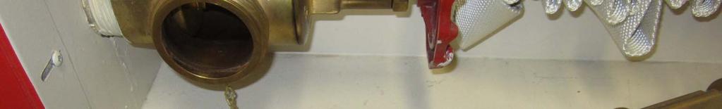
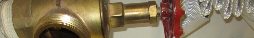
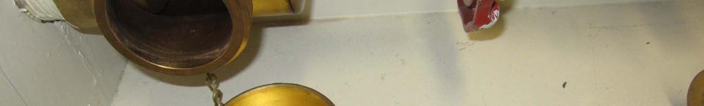
40 0 of 161 1/13/2014 8:55 AM Public Input No. 8-NFPA [ New Section after ] Components of the protective caps shall be permanently fixed and shall not be capable of becoming dislodges and causing an obstruction in either the standpipe or attached fire suppression hose/nozzles during fire operations. Additional Proposed Changes File Name 14_Collins.pdf Description Approved Cover Sheet NOTE: Supporting material is available for review at NFPA Headquarters. Submitter Full Name: MARSH COLLINS Organization: WINNIPEG FIRE PARAMEDIC SERV. Submittal Date: Mon Jun 10 09:48:41 EDT 2013 I, MARSH COLLINS, hereby irrevocably grant and assign to the National Fire Protection Association (NFPA) all and full rights in copyright in this Public Input (including both the Proposed Change and the Statement of Problem and Substantiation). I understand and intend that I acquire no rights, including rights as a joint author, in any publication of the NFPA in which this Public Input in this or another similar or derivative form is used. I hereby warrant that I am the author of this Public Input and that I have full power and authority to enter into this copyright By checking this box I affirm that I am MARSH COLLINS, and I agree to be legally bound by the above and the terms and conditions contained therein. I understand and intend that, by checking this box, I am creating an electronic signature that will, upon my

41 The City of Winnipeg Fire Paramedic Service TO: NFPA Codes and Standards Administration FROM: Marsh Collins Safety Officer Winnipeg Fire Paramedic Service. DATE: SUBJECT: Pull type 65 mm Standpipe Valve Cap potential obstruction hazard. At the time of a major fire at a construction site which was part of a major hospital complex the fire crews has problems getting water from the standpipe to extinguish the fire. Investigation after the fire revealed that: The 2 ½ hose valves had threaded connections that were protected by unthreaded caps with rubber washers attached with small screws. The Fire Crew took off the unthreaded cap by turning the cap counterclockwise as if it was a threaded cap. The counterclockwise turning motion allowed the rubber washer connected with the small screw to come undone. The cap came off and the washer stayed in place. The crew then attached the hose and turned on the water. The rubber washer obstructed the flow and resulted in a delay obtaining water for suppression. Concern Fire Crews are familiar with taking off threaded caps by turning them counterclockwise. The washers are connected by only a small screw which can easily come off. With restricted visibility or fire conditions it is possible for these washers to cause a major problem or delay with water supply during a fire. Suggested Correction Unthreaded caps with these types of washers in side should have the washer securely attached so that they cannot come off and obstruct the water supply. Please see attached pictures of the valve type and cap. Contact Information Marsh Collins Winnipeg Fire Paramedic Service Acting Safety Officer Cell (204) Desk Phone/Messages (204) mcollins@winnipeg.ca


42


43


44


45
46 1 of 161 1/13/2014 8:55 AM Public Input No. 150-NFPA [ Section No ] 4.7.5* Hose connections shall be located so that there is at least 3 1.5" in. (76.2 mm 38mm ) clearance between any adjacent object and the handle of the valve when the valve is in any position ranging from fully open to fully closed. UL Classified Hose Cabinets are only 8" deep. While UL Listed, 2-1/2" valves have handles that are 5" in diameter. This makes it impossible to place the valve so that there is 3" clearance from the back of the cabinet. The 1 1/2" dimension is the space left when installing the valve in the locations provided by the cabinet manufacturers. Submitter Full Name: Cecil Bilbo Organization: Academy of Fire Sprinkler Technology Submittal Date: Fri Jan 03 14:05:03 EST 2014 I, Cecil Bilbo, hereby irrevocably grant and assign to the National Fire Protection Association (NFPA) all and full rights in copyright in this By checking this box I affirm that I am Cecil Bilbo, and I agree to be legally bound by the above and the terms
47 2 of 161 1/13/2014 8:55 AM Public Input No. 152-NFPA [ Sections 4.8.1, ] Sections 4.8.1, Fire department connections shall be listed for a working pressure equal to or greater than the pressure requirement of the system demand Each Unless the requirements of or, are met, the fire department connection (s) shall have at least two two 21 2 in. (65 mm) connections using NH internal threaded swivel fittings having NHS threads, as specified in NFPA 1963, Standard for Fire Hose Connections. threaded swivel fitting(s) with NH standard thread, as specified in NFPA (See Sections 7.7 and 7.12 for design requirements.) Fire Where local fire department connections shall be equipped with caps to protect the system from the entry of debris do not conform to NFPA 1963, the authority having jurisdiction shall be permitted to designate the connection to be used Where the local fire department uses fittings that differ from those specified, fittings compatible with local fire department equipment shall be used and their minimum size shall be in. (65 mm). The use of threadless couplings shall be permitted where required by the authority having jurisdiction and where listed for such use Fire department connections shall be equipped with approved plugs or caps, properly secured and arranged for easy removal by fire departments Fire department connections shall be of an approved type. This language does not change the intent of the section but aligns the requirements with NFPA 13 for the types of FDC's and Caps permitted. Submitter Full Name: Cecil Bilbo Organization: Academy of Fire Sprinkler Technology Submittal Date: Fri Jan 03 14:37:33 EST 2014
48 3 of 161 1/13/2014 8:55 AM I, Cecil Bilbo, hereby irrevocably grant and assign to the National Fire Protection Association (NFPA) all and full rights in copyright in this By checking this box I affirm that I am Cecil Bilbo, and I agree to be legally bound by the above and the terms
49 4 of 161 1/13/2014 8:55 AM Public Input No. 55-NFPA [ Section No ] Fire department connections shall be equipped with caps to protect the system from the entry of debris. approved plugs or caps, properly secured and arranged for easy removal by fire deparments. Revised to correlate with section of NFPA 13. Both NFPA 13 and NFPA 14 address fire department connection so the language should be similar unless there is a justifiable need to differentiate. in this case, there is no need for differing language between NFPA 14 and 13. Submitter Full Name: Anthony Apfelbeck Organization: Altamonte Springs Building/Fire Safety Division Submittal Date: Mon Nov 18 23:19:28 EST 2013 I, Anthony Apfelbeck, hereby irrevocably grant and assign to the National Fire Protection Association (NFPA) all and full rights in copyright in this Public Input (including both the Proposed Change and the Statement of Problem and Substantiation). I understand and intend that I acquire no rights, including rights as a joint author, in any publication of the NFPA in which this Public Input in this or another similar or derivative form is used. I hereby warrant that I am the author of this Public Input and that I have full power and authority to enter into this copyright By checking this box I affirm that I am Anthony Apfelbeck, and I agree to be legally bound by the above and the terms and conditions contained therein. I understand and intend that, by checking this box, I am creating an electronic signature that will, upon my
50 5 of 161 1/13/2014 8:55 AM Public Input No. 144-NFPA [ Section No ] The number and arrangement of standpipe equipment necessary for protection shall be governed by local conditions such as the occupancy, character, and construction of the building and its accessibility the adopted building code and fire prevention code. The drivers for installation are almost always the AHJ's adopted building code or fire prevention code. The need for a standpipe system and how it is arranged should based on a code requirement and not an opinion as to the need and arragement. Submitter Full Name: Anthony Apfelbeck Organization: Altamonte Springs Building/Fire Safety Division Submittal Date: Thu Jan 02 13:33:13 EST 2014 I, Anthony Apfelbeck, hereby irrevocably grant and assign to the National Fire Protection Association (NFPA) all and full rights in copyright in this Public Input (including both the Proposed Change and the Statement of Problem and Substantiation). I understand and intend that I acquire no rights, including rights as a joint author, in any publication of the NFPA in which this Public Input in this or another similar or derivative form is used. I hereby warrant that I am the author of this Public Input and that I have full power and authority to enter into this copyright By checking this box I affirm that I am Anthony Apfelbeck, and I agree to be legally bound by the above and the terms and conditions contained therein. I understand and intend that, by checking this box, I am creating an electronic signature that will, upon my
51 6 of 161 1/13/2014 8:55 AM Public Input No. 153-NFPA [ Section No ] Standpipe and hose systems not required by the AHJ and not meeting the requirements of this standard shall be marked with a sign that reads FOR FIRE BRIGADE DEPARTMENT USE ONLY. Trained personnel will understand that these connections are for their use. However, the general public should be warned in terms that will command their respect and prevent them from operating these connections. Using the words "Fire Department" rather than "Fire Brigade" is more likely accomplish this goal. Submitter Full Name: Cecil Bilbo Organization: Academy of Fire Sprinkler Technology Submittal Date: Fri Jan 03 14:45:41 EST 2014 I, Cecil Bilbo, hereby irrevocably grant and assign to the National Fire Protection Association (NFPA) all and full rights in copyright in this By checking this box I affirm that I am Cecil Bilbo, and I agree to be legally bound by the above and the terms
52 7 of 161 1/13/2014 8:55 AM Public Input No. 64-NFPA [ Section No ] Pressure Gauges. Listed Approved pressure gauges conforming with Section 5.5 shall be connected as follows: (1) On the water side and air side of the dry pipe valve (2) At the air pump supplying the air receiver where one is provided (3) At the air receiver where one is provided (4) In each independent pipe from air supply to dry pipe system (5) At quick-opening devices [13:7.2.1] NFPA 13 has done away with the requirement for listed gauges. NFPA 14 should correlate this requirement. Submitter Full Name: Peter Schwab Organization: Wayne Automatic Fire Sprinkler Submittal Date: Tue Nov 26 10:57:55 EST 2013 I, Peter Schwab, hereby irrevocably grant and assign to the National Fire Protection Association (NFPA) all and full rights in copyright in this By checking this box I affirm that I am Peter Schwab, and I agree to be legally bound by the above and the terms
53 8 of 161 1/13/2014 8:55 AM Public Input No. 65-NFPA [ Section No ] Pressure Gauges. Listed Approved pressure gauges conforming with Section 5.5 shall be installed as follows: (1) Above and below preaction valve and below deluge valve (2) On air supply to preaction and deluge valves [13: ] NFPA 13 has done away with the requirement for listed gauges. NFPA 14 should correlate this requirement. Submitter Full Name: Peter Schwab Organization: Wayne Automatic Fire Sprinkler Submittal Date: Tue Nov 26 10:58:51 EST 2013 I, Peter Schwab, hereby irrevocably grant and assign to the National Fire Protection Association (NFPA) all and full rights in copyright in this By checking this box I affirm that I am Peter Schwab, and I agree to be legally bound by the above and the terms
54 Public Input No. 40-NFPA [ Section No. 5.3 ] 5.3 Classes of Standpipe Systems Class I Systems. A Class I standpipe system shall provide in. (65 mm) and 1 1/2 in (40mm) hose connections to supply water for use by fire departments and those trained in handling heavy fire streams Class II Systems A Class II standpipe system shall provide either in. (40 mm) hose stations to supply water for use by trained personnel or a hose connection for the fire department during initial response A minimum 1 in. (25.4 mm) hose shall be permitted to be used for hose stations in light hazard occupancies where investigated and listed for this service and where approved by the authority having jurisdiction Class III Systems. A Class III standpipe system shall provide in. (40 mm) hose stations to supply water for use by trained personnel and in. (65 mm) hose connections to supply a larger volume of water for use by fire departments and those trained in handling heavy fire streams fire fighters for mop-up operations and final extinguishment following sprinkler activiation A minimum 1 in. (25.4 mm) hose shall be permitted to be used for hose stations in light hazard occupancies where investigated and listed for this service and where approved by the authority having jurisdiction Where the building is protected throughout by an approved automatic sprinkler system, Class II hose stations for use by trained personnel shall not be required, subject to the approval of the AHJ, provided that each Class I hose connection is in. (65 mm) and is equipped with a in in. (65 mm 40 mm) reducer and a cap attached with a chain Class III standpipes meeting the provisions of shall not be required to meet the pressure requirements of or the travel requirements of This proposal, along with other proposals, was an attempt to simplify and modernize the standpipe requirements. They would also gain consistency with NFPA 13. These proposals were rejected during previous document cycles. The current NFPA 14 requirements are incongruent with modern firefighting practices. Fire departments use standpipes for firefighting operations. The most common applications are 2 ½ inch hoselines for master stream firefighting, 1 ½ inch hoselines for smaller compartment fires (such as room and contents fires), and 1 ½ inch hoselines for mop-up operations (typically after sprinkler-controlled fires). In the current NFPA 14, fire department standpipes are classified as either Class I or Class III. The only apparent difference is the presence of a 2 ½ inch by 1 ½ inch adapter for Class III standpipes. These proposals would merge the two into a single standpipe classification (Class I) that has all of the features of both existing Class I and Class III standpipes (2 ½ inch outlet size with an adapter for 1 ½ inch or 1 ¾ inch hoselines). This proposal allows fire departments to connect to standpipes with 2 ½ inch hose, 1 ¾ inch hose, 1 ½ inch hose, or a gated wye (all are common standpipe bundle arrangements utilized by modern fire departments). Class II (occupant use) standpipe systems and hose stations stay the same. Although there is a seriously diminished role for occupant use standpipes from years ago, this submittal acknowledges that there are still places, albeit rare, where the building, fire or life safety codes mandate there installation. The changes to Class III standpipes incorporate a concept from NFPA 13 referred to as small hose connections (sometimes called convenience hose connections). Small hose connection are used following sprinkler-controlled fires where relatively small amounts of water under normal pressure are used for mop-up purposes, extinguishing 9 of 161 1/13/2014 8:55 AM
55 0 of 161 1/13/2014 8:55 AM spot fires, and for salvage and overhaul purposes. Since these are not being used for interior compartment firefighting, the flows and pressures dictated by the current NFPA 14 requirements are not necessary. One of the common applications of small hose connections in NFPA 13 is for mop-up in storage occupancies following sprinkler controlled fires. In earlier rejection statement it was suggested that the change needs to be made in other codes (specifically the building code) first. This is a specious argument and something akin to a chicken or egg discussion. NFPA 14 controls the definitions for standpipe classes, not the model building or fire codes. Once this change is made to NFPA 14, the other model codes will follow with changing their definitions and the application of those definitions. Even in many of the modern fire and building codes, the requirements for standpipes for interior compartment firefighting allow either Class I or Class III; a recognition that under NFPA 14 they are basically the same thing. With these proposed definition changes, standpipe classifications become simpler: Class I standpipes become firefighting standpipe systems, Class II standpipes become occupant use and fire brigade standpipe systems, and Class III standpipes become water supplies for mop-up operations. Even if the committee does not agree with the concept of making small hose connections into a new Class III standpipe, we urge that you at least accept in principle (in part) the combining of the existing Class I and III standpipes into a new Class I, having Class II remain occupant use and fire brigade standpipes, and eliminate Class III standpipes altogether. Related Public Inputs for This Document Related Input Public Input No. 37-NFPA [Section No ] Public Input No. 38-NFPA [Section No ] Relationship Submitter Full Name: Doug Hohbein Organization: Northcentral Fire Code Develop Submittal Date: Tue Oct 15 17:17:37 EDT 2013 I, Doug Hohbein, hereby irrevocably grant and assign to the National Fire Protection Association (NFPA) all and full rights in copyright in this Public Input (including both the Proposed Change and the Statement of Problem and Substantiation). I understand and intend that I acquire no rights, including rights as a joint author, in any publication of the NFPA in which this Public Input in this or another similar or derivative form is used. I hereby warrant that I am the author of this Public Input and that I have full power and authority to enter into this copyright By checking this box I affirm that I am Doug Hohbein, and I agree to be legally bound by the above and the terms
56 1 of 161 1/13/2014 8:55 AM Public Input No. 66-NFPA [ New Section after ] Where the existing standpipe described in was originally designed for a residual pressure of 65 psi (4.5 bar) at the most remote 2 1/2" (65 mm) outlet, the minimum pressure requirement of shall not apply. This section addresses adding sprinklers to existing standpipes. The current reference to 7.10 is only applicable to flow rates. Prior to the 1993 edition of NFPA 14, 65 PSI residual was the required pressure. Many AHJ's require that the standpipes be brought up to the 100 PSI requirement which means the installation of new fire pumps. Submitter Full Name: Peter Schwab Organization: Wayne Automatic Fire Sprinkler Submittal Date: Tue Nov 26 11:08:34 EST 2013 I, Peter Schwab, hereby irrevocably grant and assign to the National Fire Protection Association (NFPA) all and full rights in copyright in this By checking this box I affirm that I am Peter Schwab, and I agree to be legally bound by the above and the terms
57 2 of 161 1/13/2014 8:55 AM Public Input No. 67-NFPA [ Section No [Excluding any Sub-Sections] ] Class II and Class III standpipe systems shall with 1 1/2 in. (40 mm) hose stations shall be automatic wet systems unless located in a facility where piping is subject to freezing and where a fire brigade is trained to operate the system without fire department intervention, in which case an automatic dry or semiautomatic dry system shall be permitted. Class III systems utilizing 1 1.2" hose stations should adhere to these rules. However, if the Class III standpipe utilizes the reducer rule, then it should fall in line with a Class I system. Submitter Full Name: Peter Schwab Organization: Wayne Automatic Fire Sprinkler Submittal Date: Tue Nov 26 11:24:23 EST 2013 I, Peter Schwab, hereby irrevocably grant and assign to the National Fire Protection Association (NFPA) all and full rights in copyright in this By checking this box I affirm that I am Peter Schwab, and I agree to be legally bound by the above and the terms
58 3 of 161 1/13/2014 8:55 AM Public Input No. 41-NFPA [ Section No ] * The automatic portion of a Class III system shall be permitted to be only what is required for a Class II system unless the Class I portion requires an automatic water supply. This proposal, along with other proposals, was an attempt to simplify and modernize the standpipe requirements. They would also gain consistency with NFPA 13. These proposals were rejected during previous document cycles. The current NFPA 14 requirements are incongruent with modern firefighting practices. Fire departments use standpipes for firefighting operations. The most common applications are 2 ½ inch hoselines for master stream firefighting, 1 ½ inch hoselines for smaller compartment fires (such as room and contents fires), and 1 ½ inch hoselines for mop-up operations (typically after sprinkler-controlled fires). In the current NFPA 14, fire department standpipes are classified as either Class I or Class III. The only apparent difference is the presence of a 2 ½ inch by 1 ½ inch adapter for Class III standpipes. These proposals would merge the two into a single standpipe classification (Class I) that has all of the features of both existing Class I and Class III standpipes (2 ½ inch outlet size with an adapter for 1 ½ inch or 1 ¾ inch hoselines). This proposal allows fire departments to connect to standpipes with 2 ½ inch hose, 1 ¾ inch hose, 1 ½ inch hose, or a gated wye (all are common standpipe bundle arrangements utilized by modern fire departments). Class II (occupant use) standpipe systems and hose stations stay the same. Although there is a seriously diminished role for occupant use standpipes from years ago, this submittal acknowledges that there are still places, albeit rare, where the building, fire or life safety codes mandate there installation. The changes to Class III standpipes incorporate a concept from NFPA 13 referred to as small hose connections (sometimes called convenience hose connections). Small hose connection are used following sprinkler-controlled fires where relatively small amounts of water under normal pressure are used for mop-up purposes, extinguishing spot fires, and for salvage and overhaul purposes. Since these are not being used for interior compartment firefighting, the flows and pressures dictated by the current NFPA 14 requirements are not necessary. One of the common applications of small hose connections in NFPA 13 is for mop-up in storage occupancies following sprinkler controlled fires. In earlier rejection statement it was suggested that the change needs to be made in other codes (specifically the building code) first. This is a specious argument and something akin to a chicken or egg discussion. NFPA 14 controls the definitions for standpipe classes, not the model building or fire codes. Once this change is made to NFPA 14, the other model codes will follow with changing their definitions and the application of those definitions. Even in many of the modern fire and building codes, the requirements for standpipes for interior compartment firefighting allow either Class I or Class III; a recognition that under NFPA 14 they are basically the same thing. With these proposed definition changes, standpipe classifications become simpler: Class I standpipes become firefighting standpipe systems, Class II standpipes become occupant use and fire brigade standpipe systems, and Class III standpipes become water supplies for mop-up operations. Even if the committee does not agree with the concept of making small hose connections into a new Class III standpipe, we urge that you at least accept in principle (in part) the combining of the existing Class I and III standpipes into a new Class I, having Class II remain occupant use and fire brigade standpipes, and eliminate Class III standpipes altogether. Related Public Inputs for This Document Related Input Public Input No. 37-NFPA [Section No ] Public Input No. 38-NFPA [Section No ] Public Input No. 40-NFPA [Section No. 5.3] Relationship
59 4 of 161 1/13/2014 8:55 AM Submitter Full Name: Doug Hohbein Organization: Northcentral Fire Code Develop Submittal Date: Tue Oct 15 17:20:28 EDT 2013 I, Doug Hohbein, hereby irrevocably grant and assign to the National Fire Protection Association (NFPA) all and full rights in copyright in this Public Input (including both the Proposed Change and the Statement of Problem and Substantiation). I understand and intend that I acquire no rights, including rights as a joint author, in any publication of the NFPA in which this Public Input in this or another similar or derivative form is used. I hereby warrant that I am the author of this Public Input and that I have full power and authority to enter into this copyright By checking this box I affirm that I am Doug Hohbein, and I agree to be legally bound by the above and the terms
60 5 of 161 1/13/2014 8:55 AM Public Input No. 154-NFPA [ Section No [Excluding any Sub-Sections] ] A listed pressure gauge having a minimum face diameter of An approved pressure gauge with a connection not smaller than 1 4 in. ( 90 6 mm) shall be connected to shall be installed at each discharge pipe from the fire pump and the public waterworks, at the pressure tank, at each main drain connection, at the air pump supplying the pressure tank, and at the top of each standpipe. This language aligns more closely with NFPA 13. NFPA 13 states: Gauges Apressure gauge with a connection not smaller than 1 4 in. (6 mm) shall be installed at the system main drain, at each main drain associated with a floor control valve, and on the inlet and outlet side of each pressurereducing valve Each gauge connection shall be equipped with a shutoff valve and provisions for draining The required pressure gauges shall be approved and shall have a maximum limit not less than twice the normal system working pressure at the point where installed Gauges shall be installed to permit removal and shall be located where they will not be subject to freezing. Submitter Full Name: Cecil Bilbo Organization: Academy of Fire Sprinkler Technology Submittal Date: Fri Jan 03 14:53:07 EST 2014 I, Cecil Bilbo, hereby irrevocably grant and assign to the National Fire Protection Association (NFPA) all and full rights in copyright in this By checking this box I affirm that I am Cecil Bilbo, and I agree to be legally bound by the above and the terms
61 6 of 161 1/13/2014 8:55 AM Public Input No. 68-NFPA [ Section No [Excluding any Sub-Sections] ] A listed pressure An approved pressure gauge having a minimum face diameter of in. (90 mm) shall be connected to each discharge pipe from the fire pump and the public waterworks, at the pressure tank, at each main drain connection, at the air pump supplying the pressure tank, and at the top of each standpipe. NFPA 13 has removed the requirement for using listed gauges. NFPA 14 should correlate this requirement. Submitter Full Name: Peter Schwab Organization: Wayne Automatic Fire Sprinkler Submittal Date: Tue Nov 26 11:27:11 EST 2013 I, Peter Schwab, hereby irrevocably grant and assign to the National Fire Protection Association (NFPA) all and full rights in copyright in this By checking this box I affirm that I am Peter Schwab, and I agree to be legally bound by the above and the terms
62 7 of 161 1/13/2014 8:55 AM Public Input No. 26-NFPA [ Section No ] Gauges shall be located in a place so that water cannot freeze to permit removal and shall be located where they will not be subject to freezing. We have seen more than a few pressure gauge installations in the field where the gauge was installed in a location where it was impossible to remove the gauge for inspection or replacement of the gauge. The existing text does not have anything about locating the gauge assembly as to permit removal of the gauge. if the gauge is inaccessible, this makes it more difficult to perform required testing and maintenance, and the building owner has additional costs of repairs to make the gauges accessible. NFPA : "System valves and gauges shall be accessible for operation, inspection, tests, and maintenance." NFPA : "Gauges shall be installed to permit removal and shall be located where they will not be subject to freezing." It only makes sense to have the Standpipe installation standard consistent with the Sprinkler installation standard with regards to accessibility and removal of the gauge. Submitter Full Name: Gregory Bartels Organization: Sprinkler Fitters LU 669-JATC Submittal Date: Tue Oct 08 14:09:50 EDT 2013 I, Gregory Bartels, hereby irrevocably grant and assign to the National Fire Protection Association (NFPA) all and full rights in copyright in this Public Input (including both the Proposed Change and the Statement of Problem and Substantiation). I understand and intend that I acquire no rights, including rights as a joint author, in any publication of the NFPA in which this Public Input in this or another similar or derivative form is used. I hereby warrant that I am the author of this Public Input and that I have full power and authority to enter into this copyright By checking this box I affirm that I am Gregory Bartels, and I agree to be legally bound by the above and the terms and conditions contained therein. I understand and intend that, by checking this box, I am creating an electronic signature that will, upon my
63 8 of 161 1/13/2014 8:55 AM Public Input No. 72-NFPA [ Section No ] Pressure Approved pressure gauges shall be installed on the upstream and the downstream sides of every pressure-regulating device installed in accordance with (6). Correlates with other first revisions in regards to gauges. Submitter Full Name: Peter Schwab Organization: Wayne Automatic Fire Sprinkler Submittal Date: Tue Nov 26 13:28:25 EST 2013 I, Peter Schwab, hereby irrevocably grant and assign to the National Fire Protection Association (NFPA) all and full rights in copyright in this By checking this box I affirm that I am Peter Schwab, and I agree to be legally bound by the above and the terms
64 9 of 161 1/13/2014 8:55 AM Public Input No. 69-NFPA [ Section No ] Except for manual dry standpipe systems, a single listed waterflow and control valve supervision shall device shall be provided for each standpipe system. Currently as written, on a manual dry system, you are not required to have valve supervision or indicate waterflow. There should be no need to monitor waterflow for a manual dry or manual wet system so the reference to dry was deleted. However, the need to not supervise a control valve on a dry system should not be allowed. A manual dry standpipe system could have multiple standpipes and hence multiple control valves. These valves should not be excluded from meeting Also, the word single was added to indicate that only one flow indicator is required for a standpipe system and a flow indicator is not required for each individual standpipe. Submitter Full Name: Peter Schwab Organization: Wayne Automatic Fire Sprinkler Submittal Date: Tue Nov 26 11:34:14 EST 2013 I, Peter Schwab, hereby irrevocably grant and assign to the National Fire Protection Association (NFPA) all and full rights in copyright in this By checking this box I affirm that I am Peter Schwab, and I agree to be legally bound by the above and the terms
65 0 of 161 1/13/2014 8:55 AM Public Input No. 70-NFPA [ Section No ] Paddle-type waterflow alarms shall be used on automatic wet standpipe systems only. There should be no need for a flow switch on a manual wet standpipe. The purpose of the flow switch is to inform the building's occupants and the fire department of a fire situation. With a manual wet standpipe, the fire department will already be on scene when water starts flowing in the standpipe. IF it is a combination system, flow switches will already be on the sprinkler system. Submitter Full Name: Peter Schwab Organization: Wayne Automatic Fire Sprinkler Submittal Date: Tue Nov 26 13:19:01 EST 2013 I, Peter Schwab, hereby irrevocably grant and assign to the National Fire Protection Association (NFPA) all and full rights in copyright in this By checking this box I affirm that I am Peter Schwab, and I agree to be legally bound by the above and the terms
66 1 of 161 1/13/2014 8:55 AM Public Input No. 71-NFPA [ New Section after ] The test connection shall have an orifice equal to or smaller than the smallest hose valve on the system. Guidance is needed for the size of the test connection. Submitter Full Name: Peter Schwab Organization: Wayne Automatic Fire Sprinkler Submittal Date: Tue Nov 26 13:21:48 EST 2013 I, Peter Schwab, hereby irrevocably grant and assign to the National Fire Protection Association (NFPA) all and full rights in copyright in this By checking this box I affirm that I am Peter Schwab, and I agree to be legally bound by the above and the terms
67 2 of 161 1/13/2014 8:55 AM Public Input No. 1-NFPA [ New Section after ] All manual dry standpipes shall be monitored with supervisory air pressure, in accordance with NFPA 72, National Fire Alarm and Signaling Code. Dry manual standpipes are notorious for leaking when charged from the FDC resulting in delaying the Fire Department to attack the fire in a prompt manner which could lead to excessive fire spread from one vehicle to another in a parking garage for instance, and so on, because the firefighters may be dragging hose up the stairs, ramps, or otherwise to fight the fire, due to the lack of integrity of the standpipe. The leaks may be a result of aging in place, vandals opening hose valves, etc. The North Texas region has required supervisory air pressure on dry manual standpipes for many years for this reason with great success. Submitter Full Name: Bob Morgan Organization: Fort Worth Fire Department Affilliation: Fire Advisory Board to the North Central Texas Council of Governments Submittal Date: Fri Apr 26 22:34:41 EDT 2013 I, Bob Morgan, hereby irrevocably grant and assign to the National Fire Protection Association (NFPA) all and full rights in copyright in this By checking this box I affirm that I am Bob Morgan, and I agree to be legally bound by the above and the terms
68 3 of 161 1/13/2014 8:55 AM Public Input No. 74-NFPA [ New Section after ] Feed mains shall be permmitted to be concealed without being monitored for integrity. Currently the way is worded, the requirement to monitor with air only applies if the standpipe is concealed. Per the definitions, the standpipe is the vertical piping supplying the hose valves. Many AHJ's interpret that this includes the feed mains to the standpipes. If the committee wants that piping monitored, then they need to change to indicate standpipe systems. Many times you will have exposed standpipes but piping running above ceilings across the first floor to supply the standpipes from the FDC. Submitter Full Name: Peter Schwab Organization: Wayne Automatic Fire Sprinkler Submittal Date: Tue Nov 26 13:38:28 EST 2013 I, Peter Schwab, hereby irrevocably grant and assign to the National Fire Protection Association (NFPA) all and full rights in copyright in this By checking this box I affirm that I am Peter Schwab, and I agree to be legally bound by the above and the terms
69 4 of 161 1/13/2014 8:55 AM Public Input No. 73-NFPA [ Section No ] Location of Dry Standpipes. Dry standpipes shall not be concealed unless the piping integrity is monitored with supervisory air pressure, in accordance with NFPA 72, National Fire Alarm and Signaling Code with supervisory air pressure. As currently written, one could construe that NFPA 72 gives guidance for the supervisory air pressure as opposed to the monitoring. Submitter Full Name: Peter Schwab Organization: Wayne Automatic Fire Sprinkler Submittal Date: Tue Nov 26 13:35:33 EST 2013 I, Peter Schwab, hereby irrevocably grant and assign to the National Fire Protection Association (NFPA) all and full rights in copyright in this By checking this box I affirm that I am Peter Schwab, and I agree to be legally bound by the above and the terms
70 5 of 161 1/13/2014 8:55 AM Public Input No. 33-NFPA [ Section No ] Antifreeze solutions shall not be used to protect standpipe system piping from freezing. Is antifreeze considered a hazard or not effective in standpipes? Heat trace is permitted, maybe antifreeze should be also. Submitter Full Name: Doug Hohbein Organization: Northcentral Fire Code Develop Submittal Date: Tue Oct 15 17:03:58 EDT 2013 I, Doug Hohbein, hereby irrevocably grant and assign to the National Fire Protection Association (NFPA) all and full rights in copyright in this Public Input (including both the Proposed Change and the Statement of Problem and Substantiation). I understand and intend that I acquire no rights, including rights as a joint author, in any publication of the NFPA in which this Public Input in this or another similar or derivative form is used. I hereby warrant that I am the author of this Public Input and that I have full power and authority to enter into this copyright By checking this box I affirm that I am Doug Hohbein, and I agree to be legally bound by the above and the terms
71 6 of 161 1/13/2014 8:55 AM Public Input No. 75-NFPA [ Section No ] Where standpipe systems are required to be protected against damage from earthquakes, standpipe systems shall be protected in accordance with Chapter 9 of NFPA 13, Standard for the Installation of Sprinkler Systems. Gives the user better guidance as where to find bracing information in NFPA 13. Submitter Full Name: Peter Schwab Organization: Wayne Automatic Fire Sprinkler Submittal Date: Tue Nov 26 13:47:07 EST 2013 I, Peter Schwab, hereby irrevocably grant and assign to the National Fire Protection Association (NFPA) all and full rights in copyright in this By checking this box I affirm that I am Peter Schwab, and I agree to be legally bound by the above and the terms
72 7 of 161 1/13/2014 8:55 AM Public Input No. 76-NFPA [ Section No ] All piping for automatic dry standpipes, manual dry standpipes, and semiautomatic standpipes shall be pitched to drain at least 1 4 in. per 10 ft (2 mm/m). Since there are only three types of standpipes without continuous water, it is appropriate to specifically indicate automatic as the other two types are specifically defined. Submitter Full Name: Peter Schwab Organization: Wayne Automatic Fire Sprinkler Submittal Date: Tue Nov 26 13:48:49 EST 2013 I, Peter Schwab, hereby irrevocably grant and assign to the National Fire Protection Association (NFPA) all and full rights in copyright in this By checking this box I affirm that I am Peter Schwab, and I agree to be legally bound by the above and the terms
73 8 of 161 1/13/2014 8:55 AM Public Input No. 155-NFPA [ New Section after ] TITLE OF NEW CONTENT The approved indicating-type valve and check valve are permitted to be located within the building. This language allows the control valve and check valve to be loacted as near the supply as possible and still remain within the buidling. The current language has been interpreted to mean that valves must be installed at the city supply mains. The only allowance for a control valve to be in a system riser is found in the annex A (3). Submitter Full Name: Cecil Bilbo Organization: Academy of Fire Sprinkler Technology Submittal Date: Fri Jan 03 14:59:57 EST 2014 I, Cecil Bilbo, hereby irrevocably grant and assign to the National Fire Protection Association (NFPA) all and full rights in copyright in this By checking this box I affirm that I am Cecil Bilbo, and I agree to be legally bound by the above and the terms
74 9 of 161 1/13/2014 8:55 AM Public Input No. 77-NFPA [ Section No ] * An approved indicating-type valve and approved check valve shall be provided in the water supply for a manual wet standpipe system. A Manual wet standpipe systems can be installed by themselves or as part of a combination system. Usually with a combination system, there will be the required valves as part of the sprinkler system requirements from either NFPA 13, Standard for the Installation of Sprinkler Systems or NFPA 13R, Standard for the Installation of Sprinkler Systems in Low Rise Residential Occupancies. In systems with only a manual wet standpipe, connection to any readily available water source is acceptable. The control and check valves only need to be approved. A common scenario is to connect the system to the potable water system which may require some form of cross connection control which may satisfy the valving requirement. There is no minimum size requirement for this connection. Added the word approved in front of check valve. Also added explanatory language in the annex in regards to manual standpipes. This is good guidance in regards to the water supply for manual wet standpipes. There should probably be even more guidance in regards to the piping up to the standpipe and if any flow or tamper requirements should apply. Submitter Full Name: Peter Schwab Organization: Wayne Automatic Fire Sprinkler Submittal Date: Tue Nov 26 13:53:13 EST 2013 I, Peter Schwab, hereby irrevocably grant and assign to the National Fire Protection Association (NFPA) all and full rights in copyright in this By checking this box I affirm that I am Peter Schwab, and I agree to be legally bound by the above and the terms
75 0 of 161 1/13/2014 8:55 AM Public Input No. 78-NFPA [ New Section after ] It is acceptable to have control valves in system piping downstream of where the fire department piping connects to the system piping. Some AHJ's will not allow control valves at any point in the system downstream of the fire department connection. This additional section adds further clarification. Submitter Full Name: Peter Schwab Organization: Wayne Automatic Fire Sprinkler Submittal Date: Tue Nov 26 14:14:26 EST 2013 I, Peter Schwab, hereby irrevocably grant and assign to the National Fire Protection Association (NFPA) all and full rights in copyright in this By checking this box I affirm that I am Peter Schwab, and I agree to be legally bound by the above and the terms
76 1 of 161 1/13/2014 8:55 AM Public Input No. 79-NFPA [ Section No ] Fire department connections Isolation valves shall not be provided with isolation valves permitted between the fire department connection and where the fire department connection piping connects to the system. The current wording is awkward as it specifically only addresses the fire department connection. This new wording clarifies that no valve is permitted between the actual connection and where the piping connects to the system piping. Submitter Full Name: Peter Schwab Organization: Wayne Automatic Fire Sprinkler Submittal Date: Tue Nov 26 14:29:22 EST 2013 I, Peter Schwab, hereby irrevocably grant and assign to the National Fire Protection Association (NFPA) all and full rights in copyright in this By checking this box I affirm that I am Peter Schwab, and I agree to be legally bound by the above and the terms
77 2 of 161 1/13/2014 8:55 AM Public Input No. 137-NFPA [ Section No ] Valves shall be provided on all standpipes, including except manual-dry standpipes, to allow isolation of a standpipe without interrupting the supply to other standpipes from the same source of supply. Removing the requirement for adding isolation valves to manual dry standpipes will increase the reliability of the manual dry standpipe systems. The requirement for valves to be added to dry standpipe systems in the 2013 edition increases the chance that a valve will be closed when the standpipe is called upon by the fire department since improperly closed valves are one of the main reason, if not the main reason, that systems do not satisfactorily perform. Since the standpipe system is dry, work can be done on any of the connected standpipes without having to worry about maintaining a water supply to the other standpipes since there is no connected water supply. Impairment procedures required by NFPA 25 should be sufficient to address the needs for working on a manual dry standpipe without isolation valves. I would even suggest that the isolation valves are not likely to be closed to perform work on a manual dry standpipe since there would essentially be no reason to isolate it for work. So when would the isolation valves actually be used? The only time that the isolation valves would be used is when the water supply was connected and there was a problem on one of the standpipes such that a firefighter would then go and shut down the standpipe to use another. The chances of this happening are likely less than having the valve improperly closed when needed. Unless there are good reasons to install these valves on dry standpipe systems, they should be exempted as proposed as they do not add value to the system. Available data suggests that improperly closed valves are a primary reason for fire protection system failures. That, along with costs incurred for installing the isolation valves, tamper switches (likely required for the valves), and the inspection testing and maintenance required for the valves and switches are reasons why isolation valves should not be required to be installed on dry standpipe systems. Submitter Full Name: Peter Larrimer Organization: US Department of Veterans Affa Submittal Date: Thu Dec 12 11:42:33 EST 2013 I, Peter Larrimer, hereby irrevocably grant and assign to the National Fire Protection Association (NFPA) all and full rights in copyright in this Public Input (including both the Proposed Change and the Statement of Problem and Substantiation). I understand and intend that I acquire no rights, including rights as a joint author, in any publication of the NFPA in which this Public Input in this or another similar or derivative form is used. I hereby warrant that I am the author of this Public Input and that I have full power and authority to enter into this copyright By checking this box I affirm that I am Peter Larrimer, and I agree to be legally bound by the above and the terms
78 3 of 161 1/13/2014 8:55 AM Public Input No. 80-NFPA [ Section No ] Listed indicating-type valves shall be provided at the standpipe for controlling branch lines for remote hose stations. This section should be deleted. By definition, a branch line will have only one hose valve. How is this any different than a hose valve on a standpipe. If you need to work on that hose valve, you have to shut down the standpipe. So why does piping any distance away from the standpipe require a valve? If the committee is adamant on keeping this requirement, then they should provide guidance as to what is a reasonable distance the branch line can run without requiring a hose valve. Submitter Full Name: Peter Schwab Organization: Wayne Automatic Fire Sprinkler Submittal Date: Tue Nov 26 14:36:06 EST 2013 I, Peter Schwab, hereby irrevocably grant and assign to the National Fire Protection Association (NFPA) all and full rights in copyright in this By checking this box I affirm that I am Peter Schwab, and I agree to be legally bound by the above and the terms
79 4 of 161 1/13/2014 8:55 AM Public Input No. 18-NFPA [ Section No ] 6.3.5* Control Valves and Check Valves on Combined (Standpipe/Sprinkler) Systems Each connection from a standpipe that is part of a combined system automatic wet standpipe to a sprinkler system shall have an individual control valve and check valve of the same size as the connection Each connection from a standpipe that is part of a combined automatic dry to a sprinkler system shall have an individual control valve the same size as the connection Manual dry, manual wet and semiautomatic wet standpipe systems shall not be connected to sprinkler systems A listed pressure-regulating device that prevents backflow shall be considered a check valve, and an additional check valve shall not be required. Currently the wording would require a check valve in a dry system trapping water at the point of connection. Additionally the current wording is unclear about whether or not sprinkler systems can be tied into all types of standpipes. While NFPA 13 requirements should clarify when sprinkler systems may be fed from standpipes it seems prudent to include language in this location. Submitter Full Name: MIKE MOREY Organization: BMW CONSTRUCTORS Submittal Date: Mon Jul 29 10:57:39 EDT 2013 I, MIKE MOREY, hereby irrevocably grant and assign to the National Fire Protection Association (NFPA) all and full rights in copyright in this Public Input (including both the Proposed Change and the Statement of Problem and Substantiation). I understand and intend that I acquire no rights, including rights as a joint author, in any publication of the NFPA in which this Public Input in this or another similar or derivative form is used. I hereby warrant that I am the author of this Public Input and that I have full power and authority to enter into this copyright By checking this box I affirm that I am MIKE MOREY, and I agree to be legally bound by the above and the terms
80 5 of 161 1/13/2014 8:55 AM Public Input No. 81-NFPA [ Section No ] Each connection from a standpipe that is part of a combined system to a sprinkler system shall have an individual control valve and check valve of the same size as the connection. There should be no need to require the control and check to be the same size as the connection. If the hydraulic calculations for the sprinkler system prove it works, then the size shouldn't be regulated. An example might be where a single saddle is drilled into the standpipe and 2 1/2" is piped out and teed to a hose connection. Then the piping is reduced to 1 1/2" for the sprinkler system because it is all that is needed. As written, the sprinkler control and check would need to be 2 1/2" which makes no sense. Submitter Full Name: Peter Schwab Organization: Wayne Automatic Fire Sprinkler Submittal Date: Tue Nov 26 14:43:37 EST 2013 I, Peter Schwab, hereby irrevocably grant and assign to the National Fire Protection Association (NFPA) all and full rights in copyright in this By checking this box I affirm that I am Peter Schwab, and I agree to be legally bound by the above and the terms
81 6 of 161 1/13/2014 8:55 AM Public Input No. 82-NFPA [ Section No ] Where the valve cannot be located at least 40 ft (12.2 m) from the building, it shall be installed in an approved location and where The indicating valve shall be installed where it is readily accessible in case of fire and not subject to damage. This section needs to be modified. It is referring to a 40'-0" dimension that is not previously indicated. The phrase "where the valve cannot be located 40 ft." indicates that a previous section required the 40 ft. In only an "approved" location is indicated. If the 40'-0" location is a requirement, then it needs to be properly codified. The language of an approved location is redundant as that is located in Submitter Full Name: Peter Schwab Organization: Wayne Automatic Fire Sprinkler Submittal Date: Tue Nov 26 14:48:20 EST 2013 I, Peter Schwab, hereby irrevocably grant and assign to the National Fire Protection Association (NFPA) all and full rights in copyright in this By checking this box I affirm that I am Peter Schwab, and I agree to be legally bound by the above and the terms
82 Public Input No. 83-NFPA [ Section No ] Where post a post -indicator valves valve cannot be used, underground valves shall an underground valve with approved roadway box, complete with T-wrench shall be permitted The valve locations, directions for their opening, and services that they control shall be plainly marked on the buildings served. Language was modified to be similar to NFPA 13. Submitter Full Name: Peter Schwab Organization: Wayne Automatic Fire Sprinkler Submittal Date: Tue Nov 26 14:56:37 EST 2013 I, Peter Schwab, hereby irrevocably grant and assign to the National Fire Protection Association (NFPA) all and full rights in copyright in this By checking this box I affirm that I am Peter Schwab, and I agree to be legally bound by the above and the terms 7 of 161 1/13/2014 8:55 AM
83 8 of 161 1/13/2014 8:55 AM Public Input No. 84-NFPA [ Section No ] * Where the standpipes are supplied from a yard main or header in another building, the connection shall be provided with a listed indicating-type valve located outside at a safe distance from the building or at the header. This section is redundant and does not offer any new information already requires the indicating valve in the water supply. Submitter Full Name: Peter Schwab Organization: Wayne Automatic Fire Sprinkler Submittal Date: Tue Nov 26 15:00:59 EST 2013 I, Peter Schwab, hereby irrevocably grant and assign to the National Fire Protection Association (NFPA) all and full rights in copyright in this By checking this box I affirm that I am Peter Schwab, and I agree to be legally bound by the above and the terms
84 9 of 161 1/13/2014 8:55 AM Public Input No. 85-NFPA [ Section No ] Except for the valve required by 6.3.2, shutoff Shutoff valves shall not be installed between the fire department connection and the system where the fire department connection piping connects to the system main piping. This more accurately describes the intent. Control valves are permitted downstream of where the fire department connection piping attaches to the system piping. Submitter Full Name: Peter Schwab Organization: Wayne Automatic Fire Sprinkler Submittal Date: Tue Nov 26 15:08:24 EST 2013 I, Peter Schwab, hereby irrevocably grant and assign to the National Fire Protection Association (NFPA) all and full rights in copyright in this By checking this box I affirm that I am Peter Schwab, and I agree to be legally bound by the above and the terms
85 0 of 161 1/13/2014 8:55 AM Public Input No. 86-NFPA [ Section No ] A listed check valve shall be installed in each fire department connection, including the connection in manual-dry systems, and located as near as practicable to the point where it joins the system. the fire department connection piping connects to the system main piping The requirements of shall apply to manual dry systems. Section has been modified for manual of style and reworded Submitter Full Name: Peter Schwab Organization: Wayne Automatic Fire Sprinkler Submittal Date: Tue Nov 26 15:15:54 EST 2013 I, Peter Schwab, hereby irrevocably grant and assign to the National Fire Protection Association (NFPA) all and full rights in copyright in this By checking this box I affirm that I am Peter Schwab, and I agree to be legally bound by the above and the terms
86 1 of 161 1/13/2014 8:55 AM Public Input No. 87-NFPA [ Section No [Excluding any Sub-Sections] ] The fire department connection shall be installed as follows: (1) Automatic Wet and Manual Wet Standpipe Systems. On the system side of the system control valve, check valve, or any pump, but on the supply side of any isolating valves required in required by (2) Automatic Dry Standpipe Systems. On the system side of the control valve and check valve and the supply side of the dry pipe valve (3) Semiautomatic Dry Standpipe Systems. On the system side of the deluge valve (4) Manual Dry Standpipe Systems. Directly connected to system piping with a check valve in the piping as required by ( 2 ) Changed the grammar. By is more appropriate than in. Also, the reference in (4) is incorrect. (Note this reference may change again based on some other PI). Submitter Full Name: Peter Schwab Organization: Wayne Automatic Fire Sprinkler Submittal Date: Tue Nov 26 15:20:04 EST 2013 I, Peter Schwab, hereby irrevocably grant and assign to the National Fire Protection Association (NFPA) all and full rights in copyright in this By checking this box I affirm that I am Peter Schwab, and I agree to be legally bound by the above and the terms
87 2 of 161 1/13/2014 8:55 AM Public Input No. 157-NFPA [ Section No ] 6.4.4* In areas subject to freezing, a listed automatic drip valve that is arranged to allow drainage without causing water damage shall be installed in the piping between the check valve and the fire department connection. A In cases where water in the piping between the system side and the fire department connection check valve would be trapped, an auxiliary drain is required. This aligns NFPA 14 with NFPA 13, providing consistency in installation requirements. Submitter Full Name: Cecil Bilbo Organization: Academy of Fire Sprinkler Technology Submittal Date: Fri Jan 03 15:10:53 EST 2014 I, Cecil Bilbo, hereby irrevocably grant and assign to the National Fire Protection Association (NFPA) all and full rights in copyright in this By checking this box I affirm that I am Cecil Bilbo, and I agree to be legally bound by the above and the terms
88 3 of 161 1/13/2014 8:55 AM Public Input No. 88-NFPA [ Section No ] In areas subject to freezing, a listed an approved automatic drip valve that is arranged to allow drainage without causing water damage shall be installed at the low point in the piping between the check valve and the fire department connection. Clarifies that the ball drip needs to be at the low point. Also, this correlates with NFPA 13 in that the ball drip in NFPA 13 is not required to be listed. Submitter Full Name: Peter Schwab Organization: Wayne Automatic Fire Sprinkler Submittal Date: Tue Nov 26 15:24:48 EST 2013 I, Peter Schwab, hereby irrevocably grant and assign to the National Fire Protection Association (NFPA) all and full rights in copyright in this By checking this box I affirm that I am Peter Schwab, and I agree to be legally bound by the above and the terms
89 4 of 161 1/13/2014 8:55 AM Public Input No. 158-NFPA [ New Section after ] TITLE OF NEW CONTENT The sign required in shall not be required where the system demand pressure is less than 150 psi (10.3 bar). This acknowledges the fact that Fire Department Engineers are trained to deliver at least 150psi to the FDC as a minimum. Submitter Full Name: Cecil Bilbo Organization: Academy of Fire Sprinkler Technology Submittal Date: Fri Jan 03 15:14:58 EST 2014 I, Cecil Bilbo, hereby irrevocably grant and assign to the National Fire Protection Association (NFPA) all and full rights in copyright in this By checking this box I affirm that I am Cecil Bilbo, and I agree to be legally bound by the above and the terms
90 5 of 161 1/13/2014 8:55 AM Public Input No. 45-NFPA [ New Section after ] The sign required in shall not be required where the system demand pressure is less than 150 psi (10.3 bar). The fire service standard for buildings equipped with fire department connections for sprinkler and standpipe systems is to pump at an initial residual pressure of 150 psi. This change simplifies the installation by not requiring a sign that is redundant in nearly all cases except for high-rise buildings, and which spares the building owner having to maintain a sign that isn't otherwise necessary, and harmonizes the standard with sections and of NFPA 13. Submitter Full Name: Stephen Leyton Organization: Protection Design and Consulting Affilliation: American Fire Sprinkler Association Submittal Date: Wed Oct 30 18:59:13 EDT 2013 I, Stephen Leyton, hereby irrevocably grant and assign to the National Fire Protection Association (NFPA) all and full rights in copyright in this Public Input (including both the Proposed Change and the Statement of Problem and Substantiation). I understand and intend that I acquire no rights, including rights as a joint author, in any publication of the NFPA in which this Public Input in this or another similar or derivative form is used. I hereby warrant that I am the author of this Public Input and that I have full power and authority to enter into this copyright By checking this box I affirm that I am Stephen Leyton, and I agree to be legally bound by the above and the terms and conditions contained therein. I understand and intend that, by checking this box, I am creating an electronic signature that will, upon my
91 6 of 161 1/13/2014 8:55 AM Public Input No. 89-NFPA [ Section No ] A sign also shall indicate the pressure required at the inlets to deliver the standpipe system demand The sign in section shall not be required when the system demand pressure is less than 150 psi (10.3 bar). The sign applies to the standpipe system demand only. Also, the 150 PSI requirement is found in NFPA 13E. Submitter Full Name: Peter Schwab Organization: Wayne Automatic Fire Sprinkler Submittal Date: Tue Nov 26 15:31:36 EST 2013 I, Peter Schwab, hereby irrevocably grant and assign to the National Fire Protection Association (NFPA) all and full rights in copyright in this By checking this box I affirm that I am Peter Schwab, and I agree to be legally bound by the above and the terms
92 7 of 161 1/13/2014 8:55 AM Public Input No. 90-NFPA [ Section No ] * Where the static pressure at a in. (65 mm) hose connection exceeds 175 psi (12.1 bar), an approved a listed pressure-regulating device shall be provided to limit static and residual pressures at the outlet of the hose connection to no more than 175 psi (12.1 bar). A device that is this important to fire fighter safety should be listed. If the committee feels that only having it approved is acceptable then they need to add this section to Submitter Full Name: Peter Schwab Organization: Wayne Automatic Fire Sprinkler Submittal Date: Tue Nov 26 15:54:41 EST 2013 I, Peter Schwab, hereby irrevocably grant and assign to the National Fire Protection Association (NFPA) all and full rights in copyright in this By checking this box I affirm that I am Peter Schwab, and I agree to be legally bound by the above and the terms
93 Public Input No. 10-NFPA [ Section No ] See the uploaded Include file for revised text of and A * Class I Systems. Class I systems shall be provided with in. (65 mm) hose connections in the following locations: (1) At the main floor landing in exit stairways (2) On each side of the wall adjacent to the exit openings of horizontal exits (3) In other than covered mall buildings, in each exit passageway at the entrance from the building areas into the passageway (4) In covered mall buildings, at the entrance to each exit passageway or exit corridor, and at the interior side of public entrances from the exterior to the mall (5) * At the highest landing of stairways with stairway access to a roof, or on roofs with a slope of less than 4 in 12 where stairways do not access the roof Hose connections shall be permitted to be located at the highest intermediate landings between floor levels in exit stairways where required by the AHJ * Where the most remote portion of a nonsprinklered floor or story is located in excess of 150 ft (45.7 m) of travel distance from a hose connection in or adjacent to a required exit or the most remote portion of a sprinklered floor or story is located in excess of 200 ft (61 m) of travel distance from a hose connection in or adjacent to a required exit, additional hose connections shall be provided, in approved locations, where required by the local fire department or the AHJ The distance requirements in shall not apply to the roof if it is not intended for occupancy * Hose connections on one side of a horizontal exit shall not be required where another outlet on that side of the horizontal exit can reach the portions of the building on the other side of the horizontal exit within the distances required by that would have been protected by the outlet that was omitted This travel distance shall be 200 ft (61 m) for sprinklered buildings and 130 ft (39.7 m) for nonsprinklered buildings. Additional Proposed Changes File Name Description Approved 14_PI_Held_Comment_14-19_Schwab_.pdf Cover Sheet 14_PI_Held_Comment_Include_Schwab_.pdf Rec Include 14_Schwab_PI_A _Horizontal_Exits.pdf Figure A NOTE: This proposal appeared as Comment (Log #12) which was held from the F12 ROC on Proposal The 2010 edition of NFPA 14 Section is arranged as a holdover from the days that NFPA used exceptions in a list following the charging statement. This comment is an attempt to bring this section up to the current manual of style. There are also some other changes filtered throughout. In Section A there is language in regards to only 8 of 161 1/13/2014 8:55 AM
94 9 of 161 1/13/2014 8:55 AM requiring one standpipe to serve the roof. This language should be codified and has been moved into the body of the standard. A note was added in regards to egress clearances for hose valve locations, especially for intermediate landings. The most significant change was in regards to horizontal exits. In the ROP, there is a conflict between the adopted language of Proposal and the wording on the annex Figure A A new annex figure has been provided. Annex language was added with guidance as to what constitutes access to the roof. Language was added to clarify that if you are installing hose connections at intermediate landings, an additional one is not needed at the top of the stairwell when it access the roof. Submitter Full Name: Peter Schwab Organization: Wayne Automatic Fire Sprinkler Submittal Date: Mon Jun 10 10:23:59 EDT 2013 I, Peter Schwab, hereby irrevocably grant and assign to the National Fire Protection Association (NFPA) all and full rights in copyright in this By checking this box I affirm that I am Peter Schwab, and I agree to be legally bound by the above and the terms
95 7.3.2* Class I Systems. When required to be provided, hose connections shall be located in accordance with Class I systems shall be provided with 2½ in. (65 mm) hose connections in the following locations: (1) At the main floor landing in exit stairways (2) On each side of the wall adjacent to the exit openings of horizontal exits (3) In other than covered mall buildings, in each exit passageway at the entrance from the building areas into the passageway (4) In covered mall buildings, at the entrance to each exit passageway or exit corridor, and at the interior side of public entrances from the exterior to the mall (5) *At the highest landing of stairways with stairway access to a roof, or on roofs with a slope of less than 4 in 12 where stairways do not access the roof A Hose connections are required now specified to be located at the main floor landing in required exit stairways. Paragraph permits hose connections to be located at intermediate landings where local fire fighting tactics require necessitate this location. Only one standpipe is necessary to serve the roof; it is not the intent to extend each standpipe to the roof level. The approach to locating hose connections with respect to exits is shown in Figure A.7.3.2(a), Figure A.7.3.2(b), and Figure A.7.3.2(c) Hose connections shall be provided at the main floor landing of required exit stairwells * When required by the AHJ, hose connections shall be permitted to be installed at the highest intermediate floor landings between floor levels in required exit stairways. A When placing hose connections on the main or intermediate landings, egress clearances as required by other codes need to be considered Hose connections shall be permitted to be located at the highest intermediate landings between floor levels in exit stairways where required by the AHJ Hose connections shall be provided on each side of the wall adjacent to the exit openings of horizontal exits * Where the most remote portion of a nonsprinklered floor or story is located in excess of 150 ft (45.7m) of travel distance from a required exit containing or adjacent to a hose connection or the most remote portion of a sprinklered floor or story is located in excess of 200 ft (61 m) of travel distance from a required exit containing or adjacent to a hose connection, additional hose connections shall be provided, in approved locations, where required by the local fire department or AHJ. A Paragraph is intended to provide local fire departments with the authority to require additional hose connections outside of or away from a 2 hour fire resistive separation. These additional hose connections could be needed to allow fire fighters to attach a fire hose in a reasonable time frame, based on the lengths of hose available on fire department standpipe packs or in carry bags. While it is recognized that outlet spacing limitations provide controls to limit the maximum hose length needed to fight a fire, thereby minimizing the physical demands on fire fighters, it is also recognized that, in some cases, based on architectural layout, additional outlets could be needed in open floor areas in order to meet spacing requirements. In such cases, such outlets are unlikely to be utilized, since there would not be a staging area for fire fighters to use when accessing the hose connection. Therefore, additional hose connections where provided to meet distance requirements, would be located in 1 hour fire resistive exit corridors wherever possible, to provide a degree of protection for fire fighters accessing the connection. Such connections also should be located as uniformly as possible from floor to floor so that fire fighters can find them easily during a fire. 14/L12/R/F2012/ROC 1
96 * Hose connections on one side of a horizontal exit shall not be required when adjacent floor areas on the same side of the horizontal exit are reachable from adjacent exit stairway hose connections as specified in and In buildings protected in accordance with NFPA 13, Standard for the Installation of Sprinkler Systems or NFPA 13R Standard for the Installation of Sprinkler Systems in Residential Occupancies up to and Including Four Stories in Height the distance from the stairway hose connection shall not exceed 200 ft (61 m) In non sprinklered buildings, the distance from the stairway hose connection shall not exceed 130 ft (39.7 m) The travel distance in section shall be measured from the hose connection Hose connections shall be provided in each exit passageway in other than covered mall buildings The hose connections required in shall be located in the exit passageway at each entrance into the building * Hose connections on one side of a horizontal exit shall not be required when adjacent floor areas on the same side of the horizontal exit are reachable from adjacent exit stairway hose connections as specified in This travel distance shall be 200 ft (61 m) for sprinklered buildings and 130 ft (39.7 m) for nonsprinklered buildings Hose connections shall be provided in covered mall buildings at the entrance to each exit passageway or exit corridor, and at the interior side of public entrances from the exterior to the mall * Hose connections shall be provided at the highest landing of stairways with stairway access to a roof. A Access to the roof can be via a stairwell that terminates at the roof level. Access could also be a permanent ladder, permanent ladder rungs or a pull down stair with a roof hatch * The hose connection required by shall not be required when hose connections are installed in accordance with A It is not necessary to provide an additional hose valve at the top of the stairwell at the main landing when the fire department procedures utilize hose connections on intermediate landings. The intermediate landing is usually located in close proximity to the top of the stairwell In stairways that do not access the roof, a hose connection shall be provided on the roof The hose connection required by shall not be required when the roof slope is 4 in 12 or greater The hose connection required by shall not be required when hose connections in accordance with are provided in the building When there are no hose connections as provided by , a single hose connection shall be provided on the roof * Additional hose connections shall be provided in unsprinklered buildings when the distance from connections required by , and to the most remote portion or story exceeds 150 ft (45.7 m). A Paragraphs and are intended to provide local fire departments with the authority to require additional hose connections outside of or away from locations required in These additional hose connections could be needed to allow fire fighters to attach a fire hose in a reasonable time frame, based on the lengths of hose available on fire department standpipe packs or in 14/L12/R/F2012/ROC 2
97 carry bags. While it is recognized that outlet spacing limitations provide controls to limit the maximum hose length needed to fight a fire, thereby minimizing the physical demands on fire fighters, it is also recognized that, in some cases, based on architectural layout, additional outlets could be needed in open floor areas in order to meet spacing requirements. In such cases, such outlets are unlikely to be utilized, since there would not be a staging area for fire fighters to use when accessing the hose connection. Therefore, additional hose connections where provided to meet distance requirements, should be located in 1 hour fire resistive exit corridors wherever possible, to provide a degree of protection for fire fighters accessing the connection. Such connections also should be located as uniformly as possible from floor to floor so that fire fighters can find them easily during a fire The distance in shall be measured from the hose connection The location of additional hose connections shall be approved by the AHJ The distance in shall not apply to the roof Where allowed by the AHJ, the hose connections required by shall be permitted to be omitted Additional hose connections shall be provided in buildings sprinklered in accordance with NFPA 13, Standard for the Installation of Sprinkler Systems or NFPA 13R Standard for the Installation of Sprinkler Systems in Residential Occupancies up to and Including Four Stories in Height when the distance from connections required by , and to the most remote portion or story exceeds 200 ft (61 m) The distance in shall be measured from the hose connection The location of additional hose connections shall be approved by the AHJ The distance in shall not apply to the roof Where allowed by the AHJ the hose connections required by shall be permitted to be omitted. 14/L12/R/F2012/ROC 3
98 FIGURE A Horizontal Exits
99 Public Input No. 104-NFPA [ Section No ] * Class I Systems. Class I systems shall be provided with in. (65 mm) hose connections in the following locations: (1) At the main floor landing in exit stairways (2) On each side of the wall adjacent to the exit openings of horizontal exits (3) In other than covered mall buildings, in each exit passageway at the entrance from the building areas into the passageway (4) In covered mall buildings, at the entrance to each exit passageway or exit corridor, and at the interior side of public entrances from the exterior to the mall (5) * At the highest landing of stairways with stairway access to a roof, or on roofs with a slope of less than 4 in 12 where stairways do not access the roof Hose connections shall be permitted to be located at the highest intermediate landings between floor levels in exit stairways where required by the AHJ * Where the most remote portion of a nonsprinklered floor or story is located in excess of 150 ft (45.7 m) of travel distance from a hose connection in or adjacent to a required exit or the most remote portion of a sprinklered floor or story is located in excess of 200 ft (61 m) of travel distance from a hose connection in or adjacent to a required exit, additional hose connections shall be provided, in approved locations, where required by the local fire department or the AHJ The distance requirements in shall not apply to the roof if it is not intended for occupancy * Hose connections on one side of a horizontal exit shall not be required where another outlet on that side of the horizontal exit can reach the portions of the building on the other side of the horizontal exit within the distances required by that would have been protected by the outlet that was omitted This travel distance shall be 200 ft (61 m) for sprinklered buildings and 130 ft (39.7 m) for nonsprinklered buildings. Additional Proposed Changes File Name 7.3.2_ReWrite.docx Description Approved Re Write In the last cycle, comments were submitted to reorganize section These were held (See PI9 & PI10). The attached document takes the 2013 edition text and reorganizes this section with minor tweaks. The rewrites in PI9 & PI10 contained some subjects that were controversial. This PI is to do the reorganization of what is in the standard and any other changes will be submitted separately. In the.doc file, there are two versions. One is legislative text and the other is as it would appear. Related Public Inputs for This Document Related Input Public Input No. 9-NFPA [Section No ] Public Input No. 10-NFPA [Section No ] Relationship 0 of 161 1/13/2014 8:55 AM
100 1 of 161 1/13/2014 8:55 AM Submitter Full Name: Peter Schwab Organization: Wayne Automatic Fire Sprinkler Submittal Date: Mon Dec 02 12:56:38 EST 2013 I, Peter Schwab, hereby irrevocably grant and assign to the National Fire Protection Association (NFPA) all and full rights in copyright in this By checking this box I affirm that I am Peter Schwab, and I agree to be legally bound by the above and the terms
101 Rewrite of Section in legislative text. At the end is a version as it would appear * Class I Systems. Where required to be provided, hose connections shall be located in accordance with Section Class I systems shall be provided with 2 ½ in. (65 mm) hose connections in the following locations: (1) At the main floor landing in exit stairways (2) On each side of the wall adjacent to the exit openings of horizontal exits (3) In other than covered mall buildings, in each exit passageway at the entrance from the building areas into the passageway (4) In covered mall buildings, at the entrance to each exit passageway or exit corridor, and at the interior side of public entrances from the exterior to the mall (5)* At the highest landing of stairways with stairway access to a roof, or on roofs with a slope of less than 4 in 12 where stairways do not access the roof A (5) Access to the roof can be via a stairwell that terminates at the roof level. Access could also be a permanent ladder, permanent ladder rungs, or a pull down stair with a roof hatch. See Figure A (5) for an example of roof outlets. A Hose connections are required now specified to be located at the main floor landing in required exit stairways. Paragraph permits hose connections to be located at intermediate landings where local fire-fighting tactics require necessitate this location. Only one standpipe is necessary to serve the roof regardless of the travel distances in ; it is not the intent to extend each standpipe to the roof level. The approach to locating hose connections with respect to exits is shown in Figure A.7.3.2(a), Figure A.7.3.2(b), and Figure A.7.3.2(c) * Hose connections shall be provided at the main floor landing of required exit stairwells. A Hose connections are required to be located at the main floor landing in required exit stairways. Paragraph permits hose connections to be located at intermediate landings where local fire-fighting tactics necessitate this location When required by the AHJ or local fire department, hose connections shall be permitted to be installed at the highest intermediate floor landings between floor levels in required exit stairways. A When locating hose connections on the main or intermediate landings, egress clearances as required by other codes need to be considered Hose connections shall be permitted to be located at the highest intermediate landings between floor levels in exit stairways where required by the AHJ Hose connections shall be provided on each side of the wall adjacent to the exit openings of horizontal exits.
102 * Where the most remote portion of a nonsprinklered floor or story is located in excess of 150 ft (45.7 m) of travel distance from a hose connection in or adjacent to a required exit or the most remote portion of a sprinklered floor or story is located in excess of 200 ft (61 m) of travel distance from a hose connection in or adjacent to a required exit, additional hose connections shall be provided, in approved locations, where required by the local fire department or the AHJ. A Paragraph is intended to provide local fire departments with the authority to require additional hose connections outside of or away from a 2-hour fire-resistive separation. These additional hose connections could be needed to allow fire fighters to attach a fire hose in a reasonable time frame, based on the lengths of hose available on fire department standpipe packs or in carry bags. While it is recognized that outlet spacing limitations provide controls to limit the maximum hose length needed to fight a fire, thereby minimizing the physical demands on fire fighters, it is also recognized that, in some cases, based on architectural layout, additional outlets could be needed in open floor areas in order to meet spacing requirements. In such cases, such outlets are unlikely to be utilized, since there would not be a staging area for fire fighters to use when accessing the hose connection. Therefore, additional hose connections where provided to meet distance requirements, would be located in 1-hour fire-resistive exit corridors wherever possible, to provide a degree of protection for fire fighters accessing the connection. Such connections also should be located as uniformly as possible from floor to floor so that fire fighters can find them easily during a fire. The 200 ft (61 m) distance allowed for sprinklered buildings could necessitate additional hose lengths in order to reach the most remote portion of a floor; however, automatic sprinklers should provide adequate control to allow time for fire fighters to extend hoses in those cases where a fire is located in the most remote area * Hose connections on one side of a horizontal exit shall not be required where another outlet on that side of the horizontal exit can reach the portions of the building on the other side of the horizontal exit within the distances required by or that would have been protected by the outlet that was omitted. A See Figure A (Rename Figure A to A ) This The travel distance in shall be 200 ft (61 m) for sprinklered buildings. and 130 ft (39.7 m) for nonsprinklered buildings The travel distance in shall be 130 ft (39.7 m) for nonsprinklered buildings The distance requirements in shall not apply to the roof if it is not intended for occupancy Hose connections shall be provided in each exit passageway in other than covered mall buildings The hose connections required in Section shall be located in the exit passageway at each entrance into the building * Hose connections on one side of a horizontal exit shall not be required where another outlet on that side of the horizontal exit can reach the portions of the building on the other side of the horizontal exit within the distances required by that would have been protected by the outlet that was omitted. A See Figure A
103 This travel distance shall be 200 ft (61 m) for sprinklered buildings and 130 ft (39.7 m) for nonsprinklered buildings Hose connections shall be provided in covered mall buildings at the entrance to each exit passageway or exit corridor, and at the interior side of public entrances from the exterior to the mall * Hose connections shall be provided at the highest landing of stairways with stairway access to a roof. A Access to the roof can be via a stairwell that terminates at the roof level. Access could also be a permanent ladder, permanent ladder rungs, or a pull down stair with a roof hatch. See Figure A for an example of a roof outlet * The hose connection required by Section shall not be required when hose connections are installed in accordance with Section A It is not necessary to provide an additional hose valve at the top of the stairwell at the main landing when the fire department procedures utilize hose connections on intermediate landings. The intermediate landing is usually located in close proximity to the top of the stairwell In stairways that do not access the roof, a hose connection shall be provided on the roof The hose connection required by Section shall not be required when the roof slope is 4 in 12 or greater The hose connection required by Section shall not be required where at least one hose connection in accordance with Section is provided in the building When there are no hose connections as provided by Section , a single hose connection shall be provided on the roof * Additional hose connections shall be provided in unsprinklered buildings when the distance from connections required by Section , Section and Section to the most remote portion or story exceeds 150 ft (45.7 m). A Paragraph is intended to provide local fire departments with the authority to require additional hose connections outside of or away from locations required in Section These additional hose connections could be needed to allow fire fighters to attach a fire hose in a reasonable time frame, based on the lengths of hose available on fire department standpipe packs or in carry bags. While it is recognized that outlet spacing limitations provide controls to limit the maximum hose length needed to fight a fire, thereby minimizing the physical demands on fire fighters, it is also recognized that, in some cases, based on architectural layout, additional outlets could be needed in open floor areas in order to meet spacing requirements. In such cases, such outlets are unlikely to be utilized, since there would not be a staging area for fire fighters to use when accessing the hose connection. Therefore, additional hose connections where provided to meet distance requirements, should be located in 1-hour fire-resistive exit corridors wherever possible, to provide a degree of protection for fire fighters accessing the
104 connection. Such connections also should be located as uniformly as possible from floor to floor so that fire fighters can find them easily during a fire The distance in Section shall be measured from the hose connection The location of additional hose connections shall be approved by the AHJ The distance requirement in Section shall not apply to the roof if it is not intended for occupancy Where allowed by the AHJ, the hose connections required by Section shall be permitted to be omitted * Additional hose connections shall be provided in buildings sprinklered in accordance with NFPA 13, Standard for the Installation of Sprinkler Systems or NFPA 13R Standard for the Installation of Sprinkler Systems in Low-Rise Residential Occupancies when the distance from connections required by Section , Section and Section to the most remote portion or story exceeds 200 ft (61 m). A Paragraph is intended to provide local fire departments with the authority to require additional hose connections outside of or away from locations required in Section These additional hose connections could be needed to allow fire fighters to attach a fire hose in a reasonable time frame, based on the lengths of hose available on fire department standpipe packs or in carry bags. While it is recognized that outlet spacing limitations provide controls to limit the maximum hose length needed to fight a fire, thereby minimizing the physical demands on fire fighters, it is also recognized that, in some cases, based on architectural layout, additional outlets could be needed in open floor areas in order to meet spacing requirements. In such cases, such outlets are unlikely to be utilized, since there would not be a staging area for fire fighters to use when accessing the hose connection. Therefore, additional hose connections where provided to meet distance requirements, should be located in 1-hour fire-resistive exit corridors wherever possible, to provide a degree of protection for fire fighters accessing the connection. Such connections also should be located as uniformly as possible from floor to floor so that fire fighters can find them easily during a fire. The 200 ft (61 m) distance allowed for sprinklered buildings could necessitate additional hose lengths in order to reach the most remote portion of a floor; however, automatic sprinklers should provide adequate control to allow time for fire fighters to extend hoses in those cases where a fire is located in the most remote area The distance in Section shall be measured from the hose connection The location of additional hose connections shall be approved by the AHJ The distance in Section shall not apply to the roof if it is not intended for occupancy Where allowed by the AHJ the hose connections required by Section shall be permitted to be omitted.
105 Below is a version as it would appear without legislative text * Class I Systems. Where required to be provided, hose connections shall be located in accordance with Section A The approach to locating hose connections with respect to exits is shown in Figure A.7.3.2(a), Figure A.7.3.2(b), and Figure A.7.3.2(c) * Hose connections shall be provided at the main floor landing of required exit stairwells. A Hose connections are required to be located at the main floor landing in required exit stairways. Paragraph permits hose connections to be located at intermediate landings where local fire-fighting tactics necessitate this location When required by the AHJ or local fire department, hose connections shall be permitted to be installed at the highest intermediate floor landings between floor levels in required exit stairways. A When locating hose connections on the main or intermediate landings, egress clearances as required by other codes need to be considered Hose connections shall be provided on each side of the wall adjacent to the exit openings of horizontal exits * Hose connections on one side of a horizontal exit shall not be required where another outlet on that side of the horizontal exit can reach the portions of the building on the other side of the horizontal exit within the distances required by or that would have been protected by the outlet that was omitted. A See Figure A The travel distance in shall be 200 ft (61 m) for sprinklered buildings The travel distance in shall be 130 ft (39.7 m) for nonsprinklered buildings Hose connections shall be provided in each exit passageway in other than covered mall buildings The hose connections required in Section shall be located in the exit passageway at each entrance into the building Hose connections shall be provided in covered mall buildings at the entrance to each exit passageway or exit corridor, and at the interior side of public entrances from the exterior to the mall * Hose connections shall be provided at the highest landing of stairways with stairway access to a roof.
106 A Access to the roof can be via a stairwell that terminates at the roof level. Access could also be a permanent ladder, permanent ladder rungs, or a pull down stair with a roof hatch. See Figure A for an example of a roof outlet * The hose connection required by Section shall not be required when hose connections are installed in accordance with Section A It is not necessary to provide an additional hose valve at the top of the stairwell at the main landing when the fire department procedures utilize hose connections on intermediate landings. The intermediate landing is usually located in close proximity to the top of the stairwell In stairways that do not access the roof, a hose connection shall be provided on the roof The hose connection required by Section shall not be required when the roof slope is 4 in 12 or greater The hose connection required by Section shall not be required where at least one hose connection in accordance with Section is provided in the building When there are no hose connections as provided by Section , a single hose connection shall be provided on the roof * Additional hose connections shall be provided in unsprinklered buildings when the distance from connections required by Section , Section and Section to the most remote portion or story exceeds 150 ft (45.7 m). A Paragraph is intended to provide local fire departments with the authority to require additional hose connections outside of or away from locations required in Section These additional hose connections could be needed to allow fire fighters to attach a fire hose in a reasonable time frame, based on the lengths of hose available on fire department standpipe packs or in carry bags. While it is recognized that outlet spacing limitations provide controls to limit the maximum hose length needed to fight a fire, thereby minimizing the physical demands on fire fighters, it is also recognized that, in some cases, based on architectural layout, additional outlets could be needed in open floor areas in order to meet spacing requirements. In such cases, such outlets are unlikely to be utilized, since there would not be a staging area for fire fighters to use when accessing the hose connection. Therefore, additional hose connections where provided to meet distance requirements, should be located in 1-hour fire-resistive exit corridors wherever possible, to provide a degree of protection for fire fighters accessing the connection. Such connections also should be located as uniformly as possible from floor to floor so that fire fighters can find them easily during a fire The distance in Section shall be measured from the hose connection The location of additional hose connections shall be approved by the AHJ.
107 The distance requirement in Section shall not apply to the roof if it is not intended for occupancy Where allowed by the AHJ, the hose connections required by Section shall be permitted to be omitted * Additional hose connections shall be provided in buildings sprinklered in accordance with NFPA 13, Standard for the Installation of Sprinkler Systems or NFPA 13R Standard for the Installation of Sprinkler Systems in Low-Rise Residential Occupancies when the distance from connections required by Section , Section and Section to the most remote portion or story exceeds 200 ft (61 m). A Paragraph is intended to provide local fire departments with the authority to require additional hose connections outside of or away from locations required in Section These additional hose connections could be needed to allow fire fighters to attach a fire hose in a reasonable time frame, based on the lengths of hose available on fire department standpipe packs or in carry bags. While it is recognized that outlet spacing limitations provide controls to limit the maximum hose length needed to fight a fire, thereby minimizing the physical demands on fire fighters, it is also recognized that, in some cases, based on architectural layout, additional outlets could be needed in open floor areas in order to meet spacing requirements. In such cases, such outlets are unlikely to be utilized, since there would not be a staging area for fire fighters to use when accessing the hose connection. Therefore, additional hose connections where provided to meet distance requirements, should be located in 1-hour fire-resistive exit corridors wherever possible, to provide a degree of protection for fire fighters accessing the connection. Such connections also should be located as uniformly as possible from floor to floor so that fire fighters can find them easily during a fire. The 200 ft (61 m) distance allowed for sprinklered buildings could necessitate additional hose lengths in order to reach the most remote portion of a floor; however, automatic sprinklers should provide adequate control to allow time for fire fighters to extend hoses in those cases where a fire is located in the most remote area The distance in Section shall be measured from the hose connection The location of additional hose connections shall be approved by the AHJ The distance in Section shall not apply to the roof if it is not intended for occupancy Where allowed by the AHJ the hose connections required by Section shall be permitted to be omitted.
108 Public Input No. 9-NFPA [ Section No ] See the uploaded Include file for edits to and A * Class I Systems. Class I systems shall be provided with in. (65 mm) hose connections in the following locations: (1) At the main floor landing in exit stairways (2) On each side of the wall adjacent to the exit openings of horizontal exits (3) In other than covered mall buildings, in each exit passageway at the entrance from the building areas into the passageway (4) In covered mall buildings, at the entrance to each exit passageway or exit corridor, and at the interior side of public entrances from the exterior to the mall (5) * At the highest landing of stairways with stairway access to a roof, or on roofs with a slope of less than 4 in 12 where stairways do not access the roof Hose connections shall be permitted to be located at the highest intermediate landings between floor levels in exit stairways where required by the AHJ * Where the most remote portion of a nonsprinklered floor or story is located in excess of 150 ft (45.7 m) of travel distance from a hose connection in or adjacent to a required exit or the most remote portion of a sprinklered floor or story is located in excess of 200 ft (61 m) of travel distance from a hose connection in or adjacent to a required exit, additional hose connections shall be provided, in approved locations, where required by the local fire department or the AHJ The distance requirements in shall not apply to the roof if it is not intended for occupancy * Hose connections on one side of a horizontal exit shall not be required where another outlet on that side of the horizontal exit can reach the portions of the building on the other side of the horizontal exit within the distances required by that would have been protected by the outlet that was omitted This travel distance shall be 200 ft (61 m) for sprinklered buildings and 130 ft (39.7 m) for nonsprinklered buildings. Additional Proposed Changes File Name 14_PI_Held_Comment_14-18_Schwab_.pdf 14_PI_Held_Comment_Include_Schwab_.pdf Description Approved Cover Sheet Rec Include NOTE: This proposal appeared as Comment (Log #20) which was held from the F12 ROC on Proposal The 2010 edition of NFPA 14 Section is arranged as a holdover from the days that NFPA used exceptions in a list following the charging statement. This comment is an attempt to bring this section up to the current manual of style. There are also some other changes filtered throughout. In Section A there is language in regards to only requiring one standpipe to serve the roof. This language should be codified and has been moved into the body of the standard. 2 of 161 1/13/2014 8:55 AM
109 3 of 161 1/13/2014 8:55 AM A note was added in regards to egress clearances for hose valve locations, especially for intermediate landings. The most significant change was in regards to horizontal exits. In the ROP, there is a conflict between the adopted language of Proposal and the wording on the annex Figure A It is not clear as to which valve on which side of the horizontal exit can be eliminated. Does the travel distance have to extend completely through the horizontal exit and reach all areas on the opposite side of the horizontal exit? This language gives credit for sprinkler systems and eliminates connections at the horizontal exit provided that the 200 foot travel distance is met. This will be in conflict with the International Building Code at first but this is the installation standard. NFPA 14 should be dictating these requirements. The building code should only be dictating when standpipes are required, not locations of hose connections, etc. Since the building code borrowed the language from NFPA 14 in the first place, they should be synchronizing with NFPA at each code cycle revision. In addition, NFPA 14 as written in the ROP stage is in conflict already with the building code because of the allowance for 200 of travel distance. This committee is made up of experts on standpipes and writing these rules definitely falls within their purview. The exception for unsprinklered buildings (130 ft) will not appear in NFPA 14 as it does in the building code. Annex language was added with guidance as to what constitutes access to the roof Language was added to clarify that if you are installing hose connections at intermediate landings, an additional one is not needed at the top of the stairwell when it access the roof. Submitter Full Name: Peter Schwab Organization: Wayne Automatic Fire Sprinkler Submittal Date: Mon Jun 10 10:11:30 EDT 2013 I, Peter Schwab, hereby irrevocably grant and assign to the National Fire Protection Association (NFPA) all and full rights in copyright in this By checking this box I affirm that I am Peter Schwab, and I agree to be legally bound by the above and the terms
110 7.3.2* Class I Systems. When required to be provided, hose connections shall be located in accordance with Section Class I systems shall be provided with 2½ in. (65 mm) hose connections in the following locations: (1) At the main floor landing in exit stairways (2) On each side of the wall adjacent to the exit openings of horizontal exits (3) In other than covered mall buildings, in each exit passageway at the entrance from the building areas into the passageway (4) In covered mall buildings, at the entrance to each exit passageway or exit corridor, and at the interior side of public entrances from the exterior to the mall (5) *At the highest landing of stairways with stairway access to a roof, or on roofs with a slope of less than 4 in 12 where stairways do not access the roof A Hose connections are required now specified to be located at the main floor landing in required exit stairways. Paragraph permits hose connections to be located at intermediate landings where local fire-fighting tactics require necessitate this location. Only one standpipe is necessary to serve the roof; it is not the intent to extend each standpipe to the roof level. The approach to locating hose connections with respect to exits is shown in Figure A.7.3.2(a), Figure A.7.3.2(b), and Figure A.7.3.2(c) Hose connections shall be provided at the main floor landing of required exit stairwells * When required by the AHJ, hose connections shall be permitted to be installed at the highest intermediate floor landings between floor levels in required exit stairways. A When placing hose connections on the main or intermediate landings, egress clearances as required by other codes need to be considered Hose connections shall be permitted to be located at the highest intermediate landings between floor levels in exit stairways where required by the AHJ Hose connections shall be provided on each side of the wall adjacent to the exit openings of horizontal exits * Where the most remote portion of a nonsprinklered floor or story is located in excess of 150 ft (45.7m) of travel distance from a required exit containing or adjacent to a hose connection or the most remote portion of a sprinklered floor or story is located in excess of 200 ft (61 m) of travel distance from a required exit containing or adjacent to a hose connection, additional hose connections shall be provided, in approved locations, where required by the local fire department or AHJ. A Paragraph is intended to provide local fire departments with the authority to require additional hose connections outside of or away from a 2-hour fire-resistive separation. These additional hose connections could be needed to allow fire fighters to attach a fire hose in a reasonable time frame, based on the lengths of hose available on fire department standpipe packs or in carry bags. While it is recognized that outlet spacing limitations provide controls to limit the maximum hose length needed to fight a fire, thereby minimizing the physical demands on fire fighters, it is also recognized that, in some cases, based on architectural layout, additional outlets could be needed in open floor areas in order to meet spacing requirements. In such cases, such outlets are unlikely to be utilized, since there would not be a staging area for fire fighters to use when accessing the hose connection. Therefore, additional hose connections where provided to meet distance requirements, would be located in 1-hour fire-resistive exit corridors wherever possible, to provide a degree of protection for fire fighters accessing the connection. Such 14/L20/R/F2012/ROC/Page 1
111 connections also should be located as uniformly as possible from floor to floor so that fire fighters can find them easily during a fire In buildings protected in accordance with NFPA 13, Standard for the Installation of Sprinkler Systems or NFPA 13R Standard for the Installation of Sprinkler Systems in Residential Occupancies up to and Including Four Stories in Height hose connections shall not be required at horizontal exits provided the distance requirements of Section are met The travel distance in Section shall be measured from the hose connection Hose connections shall be provided in each exit passageway in other than covered mall buildings The hose connections required in Section shall be located in the exit passageway at each entrance into the building * Hose connections on one side of a horizontal exit shall not be required when adjacent floor areas on the same side of the horizontal exit are reachable from adjacent exit stairway hose connections as specified in Section This travel distance shall be 200 ft (61 m) for sprinklered buildings and 130 ft (39.7 m) for nonsprinklered buildings Hose connections shall be provided in covered mall buildings at the entrance to each exit passageway or exit corridor, and at the interior side of public entrances from the exterior to the mall * Hose connections shall be provided at the highest landing of stairways with stairway access to a roof. A Access to the roof can be via a stairwell that terminates at the roof level. Access could also be a permanent ladder, permanent ladder rungs or a pull down stair with a roof hatch * The hose connection required by Section shall not be required when hose connections are installed in accordance with Section A It is not necessary to provide an additional hose valve at the top of the stairwell at the main landing when the fire department procedures utilize hose connections on intermediate landings. The intermediate landing is usually located in close proximity to the top of the stairwell In stairways that do not access the roof, a hose connection shall be provided on the roof The hose connection required by Section shall not be required when the roof slope is 4 in 12 or greater The hose connection required by Section shall not be required when hose connections in accordance with Section are provided in the building When there are no hose connections as provided by Section , a single hose connection shall be provided on the roof * Additional hose connections shall be provided in unsprinklered buildings when the distance from connections required by Section , Section and Section to the most remote portion or story exceeds 150 ft (45.7 m). A Paragraphs and are intended to provide local fire departments with the authority to require additional hose connections outside of or away from locations required in Section These additional hose connections could be needed to allow fire fighters to attach a fire hose in a reasonable time frame, based on the lengths of hose available on fire department standpipe packs or in carry bags. While it is recognized that outlet spacing limitations provide controls to limit the maximum hose length needed to fight a fire, thereby minimizing the physical demands on fire fighters, it is also recognized that, in some cases, based on architectural layout, 14/L20/R/F2012/ROC/Page 2
112 additional outlets could be needed in open floor areas in order to meet spacing requirements. In such cases, such outlets are unlikely to be utilized, since there would not be a staging area for fire fighters to use when accessing the hose connection. Therefore, additional hose connections where provided to meet distance requirements, should be located in 1-hour fire-resistive exit corridors wherever possible, to provide a degree of protection for fire fighters accessing the connection. Such connections also should be located as uniformly as possible from floor to floor so that fire fighters can find them easily during a fire The distance in Section shall be measured from the hose connection The location of additional hose connections shall be approved by the AHJ The distance in Section shall not apply to the roof Where allowed by the AHJ, the hose connections required by Section shall be permitted to be omitted Additional hose connections shall be provided in buildings sprinklered in accordance with NFPA 13, Standard for the Installation of Sprinkler Systems or NFPA 13R Standard for the Installation of Sprinkler Systems in Residential Occupancies up to and Including Four Stories in Height when the distance from connections required by Section , Section and Section to the most remote portion or story exceeds 200 ft (61 m) The distance in Section shall be measured from the hose connection The location of additional hose connections shall be approved by the AHJ The distance in Section shall not apply to the roof Where allowed by the AHJ the hose connections required by Section shall be permitted to be omitted. 14/L20/R/F2012/ROC/Page 3
113 4 of 161 1/13/2014 8:55 AM Public Input No. 51-NFPA [ Section No [Excluding any Sub-Sections] ] Class I systems shall be provided with in. (65 mm) hose connections in the following locations: (1) At the main floor each floor landing in exit stairways (2) On each side of the wall adjacent to the exit openings of horizontal exits (3) In other than covered mall buildings, in each exit passageway at the entrance from the building areas into the passageway (4) In covered mall buildings, at the entrance to each exit passageway or exit corridor, and at the interior side of public entrances from the exterior to the mall (5) * At the highest landing of stairways with stairway access to a roof, or on roofs with a slope of less than 4 in 12 where stairways do not access the roof As written, the present text basically only requires one hose connection at the main floor landing. Main floor landing is not defined. Therefore, as written, it could be interpreted to mean the main floor (i.e. ground floor or first floor). Adding "each" floor landing will require a hose connection for each floor of the builidng as intended and will allow the hose connection on each floor to be installed at the intermediate landing with the AHJ approval as opposed to the landing at the level of the building floor. Submitter Full Name: Peter Larrimer Organization: US Department of Veterans Affa Submittal Date: Thu Nov 07 14:14:17 EST 2013 I, Peter Larrimer, hereby irrevocably grant and assign to the National Fire Protection Association (NFPA) all and full rights in copyright in this Public Input (including both the Proposed Change and the Statement of Problem and Substantiation). I understand and intend that I acquire no rights, including rights as a joint author, in any publication of the NFPA in which this Public Input in this or another similar or derivative form is used. I hereby warrant that I am the author of this Public Input and that I have full power and authority to enter into this copyright By checking this box I affirm that I am Peter Larrimer, and I agree to be legally bound by the above and the terms
114 5 of 161 1/13/2014 8:55 AM Public Input No. 92-NFPA [ New Section after ] The distances in shall be reduced to 130 ft (39.7 m) when manual dry standpipes are installed in open parking garages. This new section will correlate with the IBC section Exception #3. Submitter Full Name: Peter Schwab Organization: Wayne Automatic Fire Sprinkler Submittal Date: Wed Nov 27 09:12:12 EST 2013 I, Peter Schwab, hereby irrevocably grant and assign to the National Fire Protection Association (NFPA) all and full rights in copyright in this By checking this box I affirm that I am Peter Schwab, and I agree to be legally bound by the above and the terms
115 6 of 161 1/13/2014 8:55 AM Public Input No. 140-NFPA [ New Section after ] Open stairs connecting 2 adjacent floors shall not require hose connections. Many times a convenience stair will be located in a building that requires standpipes. Many AHJ's insist that if the stair is provided, it must be required and therefore a standpipe must be provided. Many times this stair is in a lobby or open area and providing hose outlets is difficult to accomplish. Submitter Full Name: Peter Schwab Organization: Wayne Automatic Fire Sprinkler Submittal Date: Fri Dec 27 08:58:44 EST 2013 I, Peter Schwab, hereby irrevocably grant and assign to the National Fire Protection Association (NFPA) all and full rights in copyright in this By checking this box I affirm that I am Peter Schwab, and I agree to be legally bound by the above and the terms
116 7 of 161 1/13/2014 8:55 AM Public Input No. 91-NFPA [ New Section after ] Hose connections shall be permitted to be installed in the corridor or breezeway between open stairs that are not greater than 100 ft (30.5 m) apart. Additional Proposed Changes File Name Description Approved NFPA_14_Stairs.pdf Closely spaced stairs Currently the standard requires hose connections in required exit stairs. A typical arrangement found on many garden style apartments is to have (2) egress stairs spaced rather close which provides occupants two means of egress. These stairwells are generally open. Many AHJ's require a standpipe for each stairwell. Since the stairs are open, allowing a single standpipe/hose connection in the corridor should not pose any greater risk. The 100 foot limitation is a SWAG. The attached PDF is for reference only to illustrate the scenario and is not intended to be used for a figure. Submitter Full Name: Peter Schwab Organization: Wayne Automatic Fire Sprinkler Submittal Date: Wed Nov 27 08:56:16 EST 2013 I, Peter Schwab, hereby irrevocably grant and assign to the National Fire Protection Association (NFPA) all and full rights in copyright in this By checking this box I affirm that I am Peter Schwab, and I agree to be legally bound by the above and the terms

117
Public Input No. 11-NFPA [ Global Input ] Additional Proposed Changes. Statement of Problem and Substantiation for Public Input
![Public Input No. 11-NFPA [ Global Input ] Additional Proposed Changes. Statement of Problem and Substantiation for Public Input](/thumbs/94/121024521.jpg "Public Input No. 11-NFPA [ Global Input ] Additional Proposed Changes. Statement of Problem and Substantiation for Public Input") of 159 6/10/2014 8:52 AM Public Input No. 11-NFPA 14-2013 [ Global Input ] Include the provision of new design proposal in the code for Fire water system. Additional Proposed Changes File Name NFPA_Public_Input_Form.pdf
of 159 6/10/2014 8:52 AM Public Input No. 11-NFPA 14-2013 [ Global Input ] Include the provision of new design proposal in the code for Fire water system. Additional Proposed Changes File Name NFPA_Public_Input_Form.pdf
National Fire Protection Association. 1 Batterymarch Park, Quincy, MA Phone: Fax:
 National Fire Protection Association 1 Batterymarch Park, Quincy, MA 02169-7471 Phone: 617-770-3000 Fax: 617-770-0700 www.nfpa.org M E M O R A N D U M TO: FROM: Technical Committee on Standpipes Elena
TECHNICAL COMMITTEE ON SAFETY AT MOTORSPORTS VENUES. NFPA 610 First Draft Meeting. October 17-18, 2016
 TECHNICAL COMMITTEE ON SAFETY AT MOTORSPORTS VENUES NFPA 610 First Draft Meeting October 17-18, 2016 Westin Kansas City at Crown Center 1 East Pershing Road Kansas City, MO, 64108 Conference Call Access:
 Page 1 of 46 Public Input No. 17-NFPA 13E-2013 [ New Section after 3.2.4 ] New 3.2.5 Pressure-Reducing Valve. A valve designed for the purpose of reducing the downstream water pressure under both flowing
Public Input No. 88-NFPA [ New Section after ] Statement of Problem and Substantiation for Public Input
![Public Input No. 88-NFPA [ New Section after ] Statement of Problem and Substantiation for Public Input](/thumbs/84/90674952.jpg "Public Input No. 88-NFPA [ New Section after ] Statement of Problem and Substantiation for Public Input") of 201 1/13/2014 12:51 PM Public Input No. 88-NFPA 20-2013 [ New Section after 3.3.38.10 ] Add New Defination 3.3.28.11 Multiple Stage Multiple Port Pump. A single driver pump with multiple impellers operating
of 201 1/13/2014 12:51 PM Public Input No. 88-NFPA 20-2013 [ New Section after 3.3.38.10 ] Add New Defination 3.3.28.11 Multiple Stage Multiple Port Pump. A single driver pump with multiple impellers operating
Public Input No. 4-NFPA [ Section No. 4.2 ] Statement of Problem and Substantiation for Public Input. Submitter Information Verification
![Public Input No. 4-NFPA [ Section No. 4.2 ] Statement of Problem and Substantiation for Public Input. Submitter Information Verification](/thumbs/95/124845028.jpg "Public Input No. 4-NFPA [ Section No. 4.2 ] Statement of Problem and Substantiation for Public Input. Submitter Information Verification") Public Input No. 4-NFPA 214-2013 [ Section No. 4.2 ] 4.2 * Fire Risk Analysis. A fire risk analysis shall be conducted. The following are some of the factors that shall be considered in determining the
Public Input No. 4-NFPA 214-2013 [ Section No. 4.2 ] 4.2 * Fire Risk Analysis. A fire risk analysis shall be conducted. The following are some of the factors that shall be considered in determining the
 Page 1 of 198 Public Input No. 88-NFPA 20-2013 [ New Section after 3.3.38.10 ] Add New Defination 3.3.28.11 Multiple Stage Multiple Port Pump. A single driver pump with multiple impellers operating in
Public Comment No. 22-NFPA [ New Section after 1.4 ] Statement of Problem and Substantiation for Public Comment
![Public Comment No. 22-NFPA [ New Section after 1.4 ] Statement of Problem and Substantiation for Public Comment](/thumbs/96/127508363.jpg "Public Comment No. 22-NFPA [ New Section after 1.4 ] Statement of Problem and Substantiation for Public Comment") of 25 5/14/2015 2:32 PM Public Comment No. 22-NFPA 14-2014 [ New Section after 1.4 ] A.1.4 A.1.4 It is the intent of the Commi ee to recognize that future edi ons of this standard are a further refinement
of 25 5/14/2015 2:32 PM Public Comment No. 22-NFPA 14-2014 [ New Section after 1.4 ] A.1.4 A.1.4 It is the intent of the Commi ee to recognize that future edi ons of this standard are a further refinement
TECHNICAL COMMITTEE ON MANUFACTURE OF ORGANIC COATINGS First Draft Meeting Agenda March 19, :00 AM - 5:00 PM EST Web/Teleconference Meeting
 TECHNICAL COMMITTEE ON MANUFACTURE OF ORGANIC COATINGS First Draft Meeting Agenda March 19, 2014 9:00 AM - 5:00 PM EST Web/Teleconference Meeting 1. Welcome. George Seuss, Chair 2. Introductions and Update
Resolution: FR-2-NFPA Statement: The new language requires the action completed by NFPA 557 be prepared by a person that is approved.
 Public Input No. 1-NFPA 557-2012 [ New Section after 1.5.3 ] 1.6 Approved Qualifications The design shall be prepared by a person with qualifications acceptable to the AHJ. The term designer is used in
NFPA 101 SAF-RES PUBLIC COMMENTS
 Page 134 of 195 Public Comment No. 3-NFPA 101-2013 [ Section No. 28.7.6.1 ] 28.7.6.1 New draperies, curtains, and other similar loosely hanging furnishings and decorations shall be flame resistant as demonstrated
Technical Committee on Fluidized Bed Boilers
 Technical on Fluidized Bed Boilers AGENDA Web/Teleconference 1. Chair s welcome, call to order, and opening remarks at 1:00 pm EST. 2. Self-Introduction of Members and Guests 3. Approval of Minutes from
Introductions made by the Chair, committee members, NFPA Staff Liaison, Jacqueline Wilmot and Dan Gorham of the Fire Protection Research Foundation.
 NFPA Technical Committee On Fire Hose NFPA 1961 Minutes Task Group Update Underwriters Laboratory November 15 th - 16 th 2016 Tuesday, November 15 th, 2016 Meeting called to order at 8:07 AM by Chairman
Public Input No. 1-NFPA [ Global Input ] Additional Proposed Changes. Statement of Problem and Substantiation for Public Input
![Public Input No. 1-NFPA [ Global Input ] Additional Proposed Changes. Statement of Problem and Substantiation for Public Input](/thumbs/85/92902642.jpg "Public Input No. 1-NFPA [ Global Input ] Additional Proposed Changes. Statement of Problem and Substantiation for Public Input") of 280 2/6/2015 12:06 PM Public Input No. 1-NFPA 58-2013 [ Global Input ] NOTE: This public input originates from Tentative Interim Amendment 58-14-1 (TIA 1079) issued by the Standards Council on August
of 280 2/6/2015 12:06 PM Public Input No. 1-NFPA 58-2013 [ Global Input ] NOTE: This public input originates from Tentative Interim Amendment 58-14-1 (TIA 1079) issued by the Standards Council on August
TECHNICAL COMMITTEE ON FIRE CODE
 TECHNICAL COMMITTEE ON FIRE CODE M E M O R A N D U M TO: FROM: Technical Committee on Fire Code (FCC-AAA) Gregory Harrington, P.E., Staff Liaison DATE: February 3, 2011 SUBJECT: NFPA 1124 Amended CP#2
Public Comment No. 7-NFPA 30A-2013 [ Section No ]
![Public Comment No. 7-NFPA 30A-2013 [ Section No ]](/thumbs/93/111835478.jpg "Public Comment No. 7-NFPA 30A-2013 [ Section No ]") Page 1 of 13 Public Comment No. 7-NFPA 30A-2013 [ Section No. 6.4.2 ] 6.4.2 Additional Proposed Changes Each pump shall have installed on the discharge side a listed leak detection device that will provide
Page 1 of 13 Public Comment No. 7-NFPA 30A-2013 [ Section No. 6.4.2 ] 6.4.2 Additional Proposed Changes Each pump shall have installed on the discharge side a listed leak detection device that will provide
Delayed Action Closer. Mechanical self-closing device that incorporates an adjustable delay prior to the initiation of closing.
 9/20/2016 2:27 PM Second Revision No. 5006-NFPA 101-2016 [ Section No. 3.3.56 ] 3.3.56 Delayed Action Closer. Self-closing device that incorporates a delay prior to the initiation of closing. Mechanical
Agenda Technical Committee on Initiating Devices for Fire Alarm and Signaling Systems June 24-25, 2013 Saint Louis, MO
 Agenda Technical Committee on Initiating Devices for Fire Alarm and Signaling Systems June 24-25, 2013 Saint Louis, MO Item No. Subject 13-6-1 Call to Order (8:00 A.M) 13-6-2 Roll Call 13-6-3 Approval
Technical Committee on Standpipes (SPI-AAA)
") Technical Committee on Standpipes () M E M O R A N D U M DATE: March 13, 2015 TO: FROM: and Alternate Members of the Technical Committee on Standpipes () Chad Duffy, NFPA Staff Liaison Office: (617) 984-7262
Technical Committee on Standpipes () M E M O R A N D U M DATE: March 13, 2015 TO: FROM: and Alternate Members of the Technical Committee on Standpipes () Chad Duffy, NFPA Staff Liaison Office: (617) 984-7262
 Page 1 of 37 Public Input No. 1-NFPA 30A-2012 [ New Section after 1.1.2 ] 1.1.3 This code shall not apply to aircraft fuel dispensing facilities. NFPA 30A is commonly referenced, in my opinion, incorrectly,
MEMORANDUM. Technical Committee on Mercantile and Business Occupancies. NFPA 101 Second Draft Technical Committee FINAL Ballot Results (A2017)
") National Fire Protection Association 1 Batterymarch Park, Quincy, MA 02169-7471 Phone: 617-770-3000 Fax: 617-770-0700 www.nfpa.org MEMORANDUM TO: FROM: Technical Committee on Mercantile and Business Occupancies
National Fire Protection Association 1 Batterymarch Park, Quincy, MA 02169-7471 Phone: 617-770-3000 Fax: 617-770-0700 www.nfpa.org MEMORANDUM TO: FROM: Technical Committee on Mercantile and Business Occupancies
Correlating Committee on Automatic Sprinkler Systems
 Correlating Committee on Automatic Sprinkler Systems M E M O R A N D U M DATE: May 14, 2014 TO: FROM: Principal and Alternate Members of the Correlating Committee on Automatic Sprinkler Systems Matt Klaus,
Second Revision No. 20-NFPA [ Section No. 1.4 ] Supplemental Information. Submitter Information Verification. Committee Statement
![Second Revision No. 20-NFPA [ Section No. 1.4 ] Supplemental Information. Submitter Information Verification. Committee Statement](/thumbs/79/80346596.jpg "Second Revision No. 20-NFPA [ Section No. 1.4 ] Supplemental Information. Submitter Information Verification. Committee Statement") Second Revision No. 20-NFPA 14-2015 [ Section No. 1.4 ] 1.4* Equivalency. Nothing in this standard is intended to prevent the use of systems, methods, or devices of equivalent or superior quality, strength,
Second Revision No. 20-NFPA 14-2015 [ Section No. 1.4 ] 1.4* Equivalency. Nothing in this standard is intended to prevent the use of systems, methods, or devices of equivalent or superior quality, strength,
SAFETY CODES COUNCIL ORDER. BEFORE THE FIRE TECHNICAL COUNCIL On June 21, 2012
 SAFETY CODES COUNCIL #1000, 10665 Jasper Avenue N.W., Edmonton, Alberta, Canada, T5J 389 Tel: 780-413-0099 I 1-888-413-0099 Fax: 780-424-5134 I 1-888-424-5134 www.safetycodes.ab.ca COUNCIL ORDER No. 0015423
Second Revision No. 1-NFPA [ Section No. 2.2 ] Submitter Information Verification. Committee Statement
![Second Revision No. 1-NFPA [ Section No. 2.2 ] Submitter Information Verification. Committee Statement](/thumbs/76/73730261.jpg "Second Revision No. 1-NFPA [ Section No. 2.2 ] Submitter Information Verification. Committee Statement") Second Revision No. 1-NFPA 1410-2014 [ Section No. 2.2 ] 2.2 NFPA Publications. National Fire Protection Association, 1 Batterymarch Park, Quincy, MA 02169-7471. NFPA 1500, Standard on Fire Department
Second Revision No. 1-NFPA 1410-2014 [ Section No. 2.2 ] 2.2 NFPA Publications. National Fire Protection Association, 1 Batterymarch Park, Quincy, MA 02169-7471. NFPA 1500, Standard on Fire Department
3M Personal Safety Division. Standards Update. NFPA 1981/1982, 2018 Edition. March 30, 2018
 3M Personal Safety Division Standards Update NFPA 1981/1982, 2018 Edition March 30, 2018 Standards Update NFPA 1981/1982, 2018 Edition The purpose of this presentation is to provide an update on the status
Second Revision No. 1-NFPA 17A-2016 [ Section No ] Submitter Information Verification. Committee Statement. 1 of 14 6/22/2016 3:15 PM
![Second Revision No. 1-NFPA 17A-2016 [ Section No ] Submitter Information Verification. Committee Statement. 1 of 14 6/22/2016 3:15 PM](/thumbs/91/107420660.jpg "Second Revision No. 1-NFPA 17A-2016 [ Section No ] Submitter Information Verification. Committee Statement. 1 of 14 6/22/2016 3:15 PM") 1 of 14 6/22/2016 3:15 PM Second Revision No. 1-NFPA 17A-2016 [ Section No. 4.3.3 ] 4.3.3 All discharge nozzles shall be provided with caps or other suitable devices to prevent the entrance of grease vapors,
1 of 14 6/22/2016 3:15 PM Second Revision No. 1-NFPA 17A-2016 [ Section No. 4.3.3 ] 4.3.3 All discharge nozzles shall be provided with caps or other suitable devices to prevent the entrance of grease vapors,
NFPA 550 ROP Meeting Minutes
 NFPA 550 ROP Meeting Minutes NFPA Technical Committee on Fire Risk Assessment Methods (FIR-AAA) June 24, 2010 Microsoft Live Meeting 1. Call to order. The meeting was called to order at 1:00 PM on Monday,
Preliminary Agenda Technical Committee on Liquefied Petroleum Gas
 Preliminary Agenda Technical Committee on Liquefied Petroleum Gas Tuesday, March 10; All Day Wednesday, March 11; All Day DRURY PLAZA HOTEL San Antonio Riverwalk 0. Administrative. A. Meeting Schedule.
Technical Committee on Fluidized Bed Boilers
 Technical Committee on Fluidized Bed Boilers AGENDA NFPA Headquarters 1 Batterymarch Park Quincy, MA 02169 1. Chair s welcome, call to order, and opening remarks at 1:00 pm EST. 2. Self-Introduction of
Module 3. Water-Based Suppression Systems (WBSS) Part II: Highlights of Code Requirements
 Part II: Highlights of Code Requirements") Module 3 Water-Based Suppression Systems (WBSS) Part II: Highlights of Code Requirements 1 WATER-BASED SUPPRESSION SYSTEMS-PART TWO This module covers: 1. Ohio Building Code requirements and when and why
Module 3 Water-Based Suppression Systems (WBSS) Part II: Highlights of Code Requirements 1 WATER-BASED SUPPRESSION SYSTEMS-PART TWO This module covers: 1. Ohio Building Code requirements and when and why
Minutes of the Pre-ROP Meeting of the T/C on Protected Premises Signaling September 22-23, 2010 Indianapolis, IN
 Minutes of the Pre-ROP Meeting of the T/C on Protected Premises Signaling September 22-23, 2010 Indianapolis, IN Mr. Merton Bunker, Committee Chair, called the meeting to order at 8:05 on Wednesday September
MEMORANDUM. NFPA Technical Committee on Fire Code (FCC-AAA) Subject: NFPA 1 Proposed Tentative Interim Amendment (TIA) No.1045
 Subject: NFPA 1 Proposed Tentative Interim Amendment (TIA) No.1045") National Fire Protection Association 1 Batterymarch Park, Quincy, MA 02169-7471 Phone: 617-770-3000 Fax: 617-770-0700 www.nfpa.org MEMORANDUM To: From: NFPA Technical Committee on Fire Code (FCC-AAA) Gregory
National Fire Protection Association 1 Batterymarch Park, Quincy, MA 02169-7471 Phone: 617-770-3000 Fax: 617-770-0700 www.nfpa.org MEMORANDUM To: From: NFPA Technical Committee on Fire Code (FCC-AAA) Gregory
First Revision No. 49-NFPA 17A-2015 [ Detail ] Submitter Information Verification. Committee Statement 7/30/2015 1:35 PM
![First Revision No. 49-NFPA 17A-2015 [ Detail ] Submitter Information Verification. Committee Statement 7/30/2015 1:35 PM](/thumbs/85/92270546.jpg "First Revision No. 49-NFPA 17A-2015 [ Detail ] Submitter Information Verification. Committee Statement 7/30/2015 1:35 PM") of 25 7/30/2015 1:35 PM First Revision No. 49-NFPA 17A-2015 [ Detail ] Make the following change to 5.2.1.10.2: 5.2.1.10.2* The manual actuation device shall clearly identify the hazard protected and provide
of 25 7/30/2015 1:35 PM First Revision No. 49-NFPA 17A-2015 [ Detail ] Make the following change to 5.2.1.10.2: 5.2.1.10.2* The manual actuation device shall clearly identify the hazard protected and provide
M E M O R A N D U M. NFPA 5000 A2011 ROP Letter Ballot
 M E M O R A N D U M TO: FROM: NFPA Technical Committee on Building Service and Fire Protection Equipment Gregory Harrington, P.E., Staff Liaison DATE: October 1, 2009 SUBJECT: NFPA 5000 A2011 ROP Letter
Technical Committee on Incinerators and Waste Handling Systems
 Technical Committee on Incinerators and Waste Handling Systems Date: April 27, 2017 To: From: Technical Committee on Incinerators and Waste Handling Systems Eric Nette, Staff Liaison/Engineer Re: Agenda
National Fire Protection Association. 1 Batterymarch Park, Quincy, MA Phone: Fax:
 National Fire Protection Association 1 Batterymarch Park, Quincy, MA 02169-7471 Phone: 617-770-3000 Fax: 617-770-0700 www.nfpa.org M E M O R A N D U M TO: FROM: NFPA Technical Committee on Mercantile and
Technical Committee on Multiple Burner Boilers
 Technical Committee on Multiple Burner Boilers AGENDA Salt River Project PERA Club 1 Continential Drive Tempe, AZ January 14-15, 2014 1. Chair s welcome, call to order, and opening remarks at 8:00 a.m.
Subject: BSR Uniform Mechanical Code, 2015 Edition: Appeal on Proposal #333
 Paul Cabot Administrator National Fuel Gas Ms. Gabriella Davis Recording Secretary, IAPMO Standards Council International Association of Plumbing and Mechanical Officials (IAPMO) IAPMO Group World Headquarters
National Fire Protection Association. 1 Batterymarch Park, Quincy, MA Phone: Fax:
 National Fire Protection Association 1 Batterymarch Park, Quincy, MA 02169-7471 Phone: 617-770-3000 Fax: 617-770-0700 www.nfpa.org M E M O R A N D U M TO: FROM: NFPA Technical Committee on Mercantile and
Public Input No. 16-NFPA [ Section No ] Additional Proposed Changes. Statement of Problem and Substantiation for Public Input
![Public Input No. 16-NFPA [ Section No ] Additional Proposed Changes. Statement of Problem and Substantiation for Public Input](/thumbs/89/99993661.jpg "Public Input No. 16-NFPA [ Section No ] Additional Proposed Changes. Statement of Problem and Substantiation for Public Input") Public Input No. 16-NFPA 211-2014 [ Section No. 2.3.1 ] 2.3.1 ASHRAE Publications. ASHRAE, Inc., 1791 Tullie Circle, NE, Atlanta, GA 30329-2305. ASHRAE Handbook: HVAC Systems and Equipment, 2008 2012.
Public Input No. 16-NFPA 211-2014 [ Section No. 2.3.1 ] 2.3.1 ASHRAE Publications. ASHRAE, Inc., 1791 Tullie Circle, NE, Atlanta, GA 30329-2305. ASHRAE Handbook: HVAC Systems and Equipment, 2008 2012.
TECHNICAL COMMITTEE ON FIRE PUMPS
 TECHNICAL COMMITTEE ON FIRE PUMPS MEMORANDUM TO: FROM: Technical Committee on Fire Pumps Joanne Goyette, on behalf of C. Duffy / R. P. Benedetti DATE: May 2, 2011 SUBJECT: Letter Ballot on Proposals to
National Fire Protection Association. 1 Batterymarch Park, Quincy, MA Phone: Fax:
 National Fire Protection Association 1 Batterymarch Park, Quincy, MA 02169-7471 Phone: 617-770-3000 Fax: 617-770-0700 www.nfpa.org M E M O R A N D U M TO: FROM: NFPA Technical Committee on Mercantile and
International Fire Code 2006 Requirements for Construction Plan Reviews of Commercial and Multi-Family Structures
 International Fire Code 2006 Requirements for Construction Plan Reviews of Commercial and Multi-Family Structures Please note this is not an all-inclusive list. The type and complexity of your project
FIF AAA (F2014) Second Draft Meeting Web/Teleconference Meeting Agenda March 18, :00 5:00 p.m. ET
 Second Draft Meeting Web/Teleconference Meeting Agenda March 18, :00 5:00 p.m. ET") NFPA 804, Standard for Fire Protection for Advanced Light Water Reactor Electric Generating Plants, NFPA 805, Performance Based Standard for Fire Protection for Light Water Reactor Electric Generating
NFPA 804, Standard for Fire Protection for Advanced Light Water Reactor Electric Generating Plants, NFPA 805, Performance Based Standard for Fire Protection for Light Water Reactor Electric Generating
 Page 1 of 19 Committee Input No. 14-NFPA 33-2013 [ Global Input ] Type your content here... Supplemental Information File Name IndoorDraftforCI.docx Description This committee input would be added to new
The distances in shall be reduced to 130 ft (39.7 m) when manual dry standpipes are installed in open parking garages.
 when manual dry standpipes are installed in open parking garages.") of 123 6/10/2014 9:07 AM First Revision No. 117-NFPA 14-2014 [ Global Input ] 7.3.2.7.5 The distances in 7.3.2.2 shall be reduced to 130 ft (39.7 m) when manual dry standpipes are installed in open parking
of 123 6/10/2014 9:07 AM First Revision No. 117-NFPA 14-2014 [ Global Input ] 7.3.2.7.5 The distances in 7.3.2.2 shall be reduced to 130 ft (39.7 m) when manual dry standpipes are installed in open parking
M E M O R A N D U M. NFPA Technical Committee on Building Services and Fire Protection Equipment
 M E M O R A N D U M TO: FROM: NFPA Technical Committee on Building Services and Fire Protection Equipment Linda MacKay DATE: November 10, 2009 SUBJECT: NFPA 5000 A2011 ROP Letter Ballot Final Results The
Public Comment No. 2-NFPA [ Section No ]
![Public Comment No. 2-NFPA [ Section No ]](/thumbs/93/114140985.jpg "Public Comment No. 2-NFPA [ Section No ]") Page 1 of 13 Public Comment No. 2-NFPA 703-2013 [ Section No. 2.3.1 ] 2.3.1 ASTM Publications. ASTM International, P.O. Box C700, 100 Barr Harbor Drive, West Conshohocken, PA 19428-2959. ASTM D 2898, Standard
Page 1 of 13 Public Comment No. 2-NFPA 703-2013 [ Section No. 2.3.1 ] 2.3.1 ASTM Publications. ASTM International, P.O. Box C700, 100 Barr Harbor Drive, West Conshohocken, PA 19428-2959. ASTM D 2898, Standard
M E M O R A N D U M. According to the final ballot results, all ballot items received the necessary affirmative votes to pass ballot.
 National Fire Protection Association 1 Batterymarch Park, Quincy, MA 02169-7471 Phone: 617-770-3000 Fax: 617-770-0700 www.nfpa.org M E M O R A N D U M To: From: NFPA Technical Committee on Helicopter Facilities
 Page 1 of 190 Public Input No. 22-NFPA 55-2013 [ Global Input ] Throughout the document, delete ANSI from ANSI/ASME B31.3. Current Text: (multiple locations) ANSI/ASME B31.3 (found in Subsections: 2.3.2
NFPA 79 - Second Draft Meeting July 8-10, DoubleTree Hotel, Portland, ME
 National Fire Protection Association 1 Batterymarch Park, Quincy, MA 02169-7471 Phone: 617-770-3000 Fax: 617-770-0700 www.nfpa.org AGENDA NFPA TECHNICAL COMMITTEE ON ELECTRICAL EQUIPMENT OF INDUSTRIAL
Public Comment No. 3-NFPA [ Global Input ] Statement of Problem and Substantiation for Public Comment. Submitter Information Verification
![Public Comment No. 3-NFPA [ Global Input ] Statement of Problem and Substantiation for Public Comment. Submitter Information Verification](/thumbs/95/124619225.jpg "Public Comment No. 3-NFPA [ Global Input ] Statement of Problem and Substantiation for Public Comment. Submitter Information Verification") Public Comment No. 3-NFPA 1408-2013 [ Global Input ] Type your content here... NFPA 1408, Standard for Training Fire Service Personnel in the Operation, Care, Use and Maintenance of Thermal Imagers Revise
Public Comment No. 3-NFPA 1408-2013 [ Global Input ] Type your content here... NFPA 1408, Standard for Training Fire Service Personnel in the Operation, Care, Use and Maintenance of Thermal Imagers Revise
First Revision No. 1-NFPA [ Section No ] Submitter Information Verification. Committee Statement 4/15/ :08 AM
![First Revision No. 1-NFPA [ Section No ] Submitter Information Verification. Committee Statement 4/15/ :08 AM](/thumbs/90/103874800.jpg "First Revision No. 1-NFPA [ Section No ] Submitter Information Verification. Committee Statement 4/15/ :08 AM") First Revision No. 1-NFPA 1403-2015 [ Section No. 1.2.1 ] 1.2.1 The purpose of this standard shall be to provide a process for conducting live fire training evolutions to ensure that they are conducted
First Revision No. 1-NFPA 1403-2015 [ Section No. 1.2.1 ] 1.2.1 The purpose of this standard shall be to provide a process for conducting live fire training evolutions to ensure that they are conducted
home smoke candles alarms electrical burns smoking medical oxygen cooking FIREFIGHTING MATCHES & LIGHTERS SPRINKLERS
 FIREFIGHTING home smoke alarms REGULATIONS GOVERNING THE NFPA EDUCATIONAL MESSAGES DESK REFERENCE FOR THE FIRE SERVICE AND FIRE AND LIFE SAFETY EDUCATORS MATCHES & LIGHTERS medical oxygen cooking FIRE
NFPA s Standards Development Process
 NFPA s Standards Development Process Revision Cycle 104 weeks or 141 weeks Guiding Principles Due process Openness Lack of dominance Seek society s balance between: Acceptable risk Commitment of resources
TECHNICAL COMMITTEE ON WATER-COOLING TOWERS. First Draft Meeting Agenda. February 7, :00 AM - 5:00 PM EST Web/Teleconference Meeting
 TECHNICAL COMMITTEE ON WATER-COOLING TOWERS First Draft Meeting Agenda February 7, 2014 10:00 AM - 5:00 PM EST Web/Teleconference Meeting 1. Welcome. Robert Smith, Chair 2. Introductions and Update of
CALIFORNIA DEPARTMENT of FORESTRY and FIRE PROTECTION OFFICE OF THE STATE FIRE MARSHAL UL 300
 CALIFORNIA DEPARTMENT of FORESTRY and FIRE PROTECTION OFFICE OF THE STATE FIRE MARSHAL UL 300 FREQUENTLY ASKED QUESTIONS CONCERNING COMMERCIAL COOKING PROTECTION Published by FIRE ENGINEERING DIVISION
Center for Life Safety Education
 Center for Life Safety Education Fire Sprinklers 101 Introduction, Building Codes, and Water Supplies Reprinted with permission from NFPA 13, Installation of Sprinkler Systems, Copyright 2007, National
Public Comment No. 20-NFPA [ Section No ] Statement of Problem and Substantiation for Public Comment Related Item
![Public Comment No. 20-NFPA [ Section No ] Statement of Problem and Substantiation for Public Comment Related Item](/thumbs/75/72069029.jpg "Public Comment No. 20-NFPA [ Section No ] Statement of Problem and Substantiation for Public Comment Related Item") of 27 9/2/2014 9:27 AM Public Comment No. 20-NFPA 24-2014 [ Section No. 2.3.2 ] 2.3.2 ASTM Publications. ASTM International, 100 Barr Harbor Drive, P.O. Box C700, West Conshohocken, PA 19428-2959. ASTM
of 27 9/2/2014 9:27 AM Public Comment No. 20-NFPA 24-2014 [ Section No. 2.3.2 ] 2.3.2 ASTM Publications. ASTM International, 100 Barr Harbor Drive, P.O. Box C700, West Conshohocken, PA 19428-2959. ASTM
1. Call to Order. The meeting was called to order at 1:05 PM. (See Enclosure A [Agenda])
![1. Call to Order. The meeting was called to order at 1:05 PM. (See Enclosure A [Agenda])](/thumbs/92/110818065.jpg "1. Call to Order. The meeting was called to order at 1:05 PM. (See Enclosure A [Agenda])") FINAL MINUTES Healthcare Interpretations Task Force Tuesday, June 15, 2016 Mandalay Bay Convention Center South Convention Center, Level 2 Room Surf F Las Vegas, NV 1. Call to Order. The meeting was called
FINAL MINUTES Healthcare Interpretations Task Force Tuesday, June 15, 2016 Mandalay Bay Convention Center South Convention Center, Level 2 Room Surf F Las Vegas, NV 1. Call to Order. The meeting was called
Delayed Action Closer. Mechanical self-closing device that incorporates an adjustable delay prior to the initiation of closing.
 Second Revision No. 5006-NFPA 101-2016 [ Section No. 3.3.56 ] 3.3.56 Delayed Action Closer. Self-closing device that incorporates a delay prior to the initiation of closing. Mechanical self-closing device
Committee on 51A M E M O R A N D U M. NFPA Technical Committee on Industrial and Medical Gases
 Committee on 51A M E M O R A N D U M To: From: NFPA Technical Committee on Industrial and Medical Gases Patti Mucci, Administrative Assistant Date: June 14, 2010 Subject: NFPA 51A ROC Letter Ballot Circulation
National Fire Protection Association. 1 Batterymarch Park, Quincy, MA Phone: Fax:
 National Fire Protection Association 1 Batterymarch Park, Quincy, MA 02169-7471 Phone: 617-770-3000 Fax: 617-770-0700 www.nfpa.org MEMORANDUM TO: FROM: Technical Committee on Residential Occupancies Kelly
NFPA 72 is in the same cycle as NFPA 80. The extracted text will be updated with a Second Revision during the second draft meeting.
 Input No. 7-NFPA 80-2013 [ Section No. 3.3.8 ] 3.3.8 Automatic Fire Detector. A device designed to detect the presence of a fire signature and to initiate action. For the purpose of this standard, automatic
National Fire Protection Association (NFPA) Fire Service Occupational Safety and Health Technical Committee Meeting March 14 15, 2012 San Diego, CA
 Fire Service Occupational Safety and Health Technical Committee Meeting March 14 15, 2012 San Diego, CA") National Fire Protection Association (NFPA) Fire Service Occupational Safety and Health Technical Committee Meeting March 14 15, 2012 San Diego, CA The NFPA 1521 Task Group and NFPA 1561 Task Group, established
National Fire Protection Association (NFPA) Fire Service Occupational Safety and Health Technical Committee Meeting March 14 15, 2012 San Diego, CA The NFPA 1521 Task Group and NFPA 1561 Task Group, established
ANSI/NETA Standards Update
 Specifications and Standards Activity ANSI/NETA Standards Update NOW AVAILABALE!!!! NETA Standard for Acceptance Testing Specifications for Electrical Power Equipment and Systems The NETA Acceptance Testing
Public Input No. 52-NFPA [ Section No [Excluding any Sub-Sections] ]
![Public Input No. 52-NFPA [ Section No [Excluding any Sub-Sections] ]](/thumbs/81/83983503.jpg "Public Input No. 52-NFPA [ Section No [Excluding any Sub-Sections] ]") 8 of 93 11/6/2015 7:41 AM Public Input No. 52-NFPA 30-2015 [ Section No. 21.2 [Excluding any Sub-Sections] ] For the purpose of this chapter, the term in this section shall have the definitions given.
8 of 93 11/6/2015 7:41 AM Public Input No. 52-NFPA 30-2015 [ Section No. 21.2 [Excluding any Sub-Sections] ] For the purpose of this chapter, the term in this section shall have the definitions given.
26 of 128 9/23/2014 9:25 AM
 26 of 128 9/23/2014 9:25 AM Second Revision No. 105-NFPA 72-2014 [ Global Comment ] Revise the Annex F figures that include a smoke detector symbol (hexagon with a whisp of smoke) so that the new smoke
NFPA 30 FLC-SWC First Revisions Page 1 of 10 11/6/2015 9:21 AM. First Revision No. 208-NFPA [ Section No ]
![NFPA 30 FLC-SWC First Revisions Page 1 of 10 11/6/2015 9:21 AM. First Revision No. 208-NFPA [ Section No ]](/thumbs/89/98133759.jpg "NFPA 30 FLC-SWC First Revisions Page 1 of 10 11/6/2015 9:21 AM. First Revision No. 208-NFPA [ Section No ]") of 46 11/6/2015 9:21 AM First Revision No. 208-NFPA 30-2015 [ Section No. 9.3.3.1 ] 9.3.3.1 Storage of liquids shall not physically obstruct a means of egress. Submittal Date: Wed Sep 09 18:24:20 EDT 2015
of 46 11/6/2015 9:21 AM First Revision No. 208-NFPA 30-2015 [ Section No. 9.3.3.1 ] 9.3.3.1 Storage of liquids shall not physically obstruct a means of egress. Submittal Date: Wed Sep 09 18:24:20 EDT 2015
SC # /16/17/18/19/23/24 D#03-24
 SC #03-7-15/16/17/18/19/23/24 D#03-24 Casey C. Grant, P.E. Secretary, Standards Council 26 July 2003 To: Interested Parties Subject: Standards Council Decision (Final): D#03-24 Standards Council Agenda
Public Input No. 1-NFPA [ Global Input ] Statement of Problem and Substantiation for Public Input. Submitter Information Verification
![Public Input No. 1-NFPA [ Global Input ] Statement of Problem and Substantiation for Public Input. Submitter Information Verification](/thumbs/93/113334715.jpg "Public Input No. 1-NFPA [ Global Input ] Statement of Problem and Substantiation for Public Input. Submitter Information Verification") Public Input No. 1-NFPA 36-2013 [ Global Input ] Revise the document to eliminate the use of "Exception" text. The use of "Exception" text is inconsistent with the Manual of Style. Exception text should
Public Input No. 1-NFPA 36-2013 [ Global Input ] Revise the document to eliminate the use of "Exception" text. The use of "Exception" text is inconsistent with the Manual of Style. Exception text should
Structural Firefighting Policy
 Section Policy Number Effective Date C C1 09/01/2015 Policy Issued As Reference Policy # B1-B4, B6, C2-C10, C12, D1, and TBD Subject Approval: Policy Donald Norman, Fire Chief PURPOSE The purpose of this
SURREY FIRE SERVICE. Construction Fire Safety Plan Bulletin
 SURREY FIRE SERVICE Construction Fire Safety Plan Bulletin The B.C. Fire Code requires building owners/contractors to comply with the requirements of the BC Fire Code 5.6 Construction and Demolition Sites
SACRAMENTO FIRE DEPARTMENT FIRE PREVENTION DIVISION FIRE DEPARTMENT DEVELOPMENT SERVICES UNIT CONTRATOR INFORMATION PACKET
 SACRAMENTO FIRE DEPARTMENT FIRE PREVENTION DIVISION FIRE DEPARTMENT DEVELOPMENT SERVICES UNIT CONTRATOR INFORMATION PACKET 1 SACRAMENTO FIRE DEPARTMENT FIRE PREVENTION DIVISION FIRE DEPARTMENT DEVELOPMENT
9/20/2016 2:53 PM. Second Revision No NFPA [ Section No ] Supplemental Information. Submitter Information Verification
![9/20/2016 2:53 PM. Second Revision No NFPA [ Section No ] Supplemental Information. Submitter Information Verification](/thumbs/95/123325533.jpg "9/20/2016 2:53 PM. Second Revision No NFPA [ Section No ] Supplemental Information. Submitter Information Verification") Second Revision No. 2011-NFPA 101-2016 [ Section No. 14.2.2.2.4 ] 14.2.2.2.4* Classroom Door Locking to Prevent Unwanted Entry. Classroom doors shall be permitted to be locked to prevent unwanted entry
Second Revision No. 2011-NFPA 101-2016 [ Section No. 14.2.2.2.4 ] 14.2.2.2.4* Classroom Door Locking to Prevent Unwanted Entry. Classroom doors shall be permitted to be locked to prevent unwanted entry
Meeting Agenda Technical Committee on Fire Service Occupational Safety and Health January 8 th -10 th, 2013 San Diego, Ca.
 Meeting Agenda Technical Committee on Fire Service Occupational Safety and Health January 8 th -10 th, 2013 San Diego, Ca. I. Welcome and call to order of the TC by the Chair at 8am. II. Introductions-
SUWANNEE RIVER WATER MANAGEMENT DISTRICT REQUEST FOR BID NO. 15/16-003AO FIRE ALARM SYSTEM INSTALLATION AND MONITORING.
 SUWANNEE RIVER WATER MANAGEMENT DISTRICT REQUEST FOR BID NO. 15/16-003AO FIRE ALARM SYSTEM INSTALLATION AND MONITORING Table of Contents Section Title Page 1 Introduction 2 2 Proposed Schedule 2 3 Instructions
 Page 1 of 73 Print Reload Page Close Show Cart Public Input No. 13-NFPA 170-2012 [ Global Input ] 3.3.3 Photoluminescent. A type of sign that is self-energized with respect to luminosity and requires no
Table EXIT ACCESS TRAVEL DISTANCE a OCCUPANCY SYSTEM SYSTEM. A, E, F-1, I-1, M, b,d R, S-1. B c. F-2, S-2, U c
 Table 1015.1 EXIT ACCESS TRAVEL DISTANCE a WITHOUT SPRINKLER WITH SPRINKLER OCCUPANCY SYSTEM SYSTEM A, E, F-1, I-1, M, 200 250 b,d R, S-1 B 200 300 c F-2, S-2, U 300 400 c No Change to Other Entries in
1 Batterymarch Park, Quincy, MA Phone: Fax: M E M O R A N D U M
 National Fire Protection Association 1 Batterymarch Park, Quincy, MA 02169-7471 Phone: 617-770-3000 Fax: 617-770-0700 www.nfpa.org M E M O R A N D U M TO: FROM: NFPA Technical Committee on Fire Pumps Patti
Kidde Nitrogen Inert Gas Clean Agent Fire Suppression System
 1. GENERAL 1.1 INTENT OF SPECIFICATIONS A. This specification details the requirements for an engineered inert gas fire suppression system Model Kidde Nitrogen. These requirements, combined with good engineering
Bold items are particular to the City of Euless
 EULESS FIRE DEPARTMENT FIRE MARSHAL S OFFICE INFORMATION LINE: Revised 8/2004 Fire Chief Lee Koontz Fire Marshal Paul Smith EFD-FMO 3-1 2003 International Fire & Building Code as Amended NFPA Standards
TECHNICAL COMMITTEE ON FIRE CODE
 TECHNICAL COMMITTEE ON FIRE CODE M E M O R A N D U M TO: FROM: Technical Committee on Fire Code (FCC-AAA) Gregory Harrington, P.E., Staff Liaison DATE: March 18, 2010 SUBJECT: NFPA 1 A2011 ROP Letter Ballot
Rancho Cucamonga Fire Protection District Prevention Bureau Standard
 Rancho Cucamonga Fire Protection District Prevention Bureau Standard Title: Fire Alarm and Monitoring Systems Standard # 9-3 Effective: May 2002 Number of Pages: 7 Updated: December 2016 for consistency
TABLE OF CONTENTS Part 6 Legal Basis for Fire Safety Planning... 2
 TABLE OF CONTENTS Part 6 Legal Basis for Fire Safety Planning... 2 6.1] GENERAL... 2 6.2] EXCERPTS FROM 2012 BC FIRE CODE PART 2 BUILDING AND OCCUPANT FIRE SAFETY... 3 6.3] EXCERPTS FROM 2012 BC FIRE CODE
Public Comment No. 3-NFPA [ Chapter 7 ]
![Public Comment No. 3-NFPA [ Chapter 7 ]](/thumbs/92/109131250.jpg "Public Comment No. 3-NFPA [ Chapter 7 ]") Page 1 of 8 Public Comment No. 3-NFPA 405-2013 [ Chapter 7 ] Chapter 7 ARFF Personnel Safety and Safety Management 7.1 Scope. This chapter identifies the knowledge and skills necessary to ensure ARFF personnel
Page 1 of 8 Public Comment No. 3-NFPA 405-2013 [ Chapter 7 ] Chapter 7 ARFF Personnel Safety and Safety Management 7.1 Scope. This chapter identifies the knowledge and skills necessary to ensure ARFF personnel
D. The work addressed in this section consists of a fire protection system, which may include coordination with one or more of the following:
 PART 1 GENERAL 1.01 Scope of Standard A. This standard provides general requirements of Sam Houston State University for the design and construction of standpipe systems to include combination standpipe
1 Batterymarch Park, Quincy, MA Phone: Fax: M E M O R A N D U M
 National Association 1 Batterymarch Park, Quincy, MA 02169-7471 Phone: 617-770-3000 Fax: 617-770-0700 www.nfpa.org M E M O R A N D U M TO: FROM: Technical Committee on Industrial and Medical Gases Joanne
Public Comment No. 13-NFPA [ Section No ]
![Public Comment No. 13-NFPA [ Section No ]](/thumbs/89/98249010.jpg "Public Comment No. 13-NFPA [ Section No ]") Public Comment No. 13-NFPA 30-2013 [ Section No. 2.3.3 ] 2.3.3 ASTM Publications. ASTM International, 100 Barr Harbor Drive, P.O. Box C700, West Conshohocken, PA 19428-2959. ASTM A 395/A395M, Standard
Public Comment No. 13-NFPA 30-2013 [ Section No. 2.3.3 ] 2.3.3 ASTM Publications. ASTM International, 100 Barr Harbor Drive, P.O. Box C700, West Conshohocken, PA 19428-2959. ASTM A 395/A395M, Standard
1. Welcome. Robert Smith, Chair. 2. Introductions and Update of Committee Roster. (attached)
") TECHNICAL COMMITTEE ON WATER-COOLING TOWERS NFPA 214 (F2015) Second Draft Meeting Agenda February 17, 2014 10:00 AM - 1:00 PM EST Web/Teleconference Meeting 1. Welcome. Robert Smith, Chair 2. Introductions
TECHNICAL COMMITTEE ON WATER-COOLING TOWERS NFPA 214 (F2015) Second Draft Meeting Agenda February 17, 2014 10:00 AM - 1:00 PM EST Web/Teleconference Meeting 1. Welcome. Robert Smith, Chair 2. Introductions
Pre-First Draft Meeting Technical Committee on Wastewater Treatment Plants On line/conference Call November 20, PM EDT
 Pre-First Draft Meeting Technical Committee on Wastewater Treatment Plants On line/conference Call vember 20, 2012 2-4 PM EDT (1-3 PM CT; 12-2 PM MT; 11-1 PM PT) 1. Welcome-Glenn McGinley, Committee Chair
Remove the "Exception" text to be consistent with direction provided in the MOS.
 of 37 1/11/2017 7:38 AM Public Input No. 9-NFPA 88A-2015 [ Global Input ] Remove the "Exception" text to be consistent with direction provided in the MOS. The current language in 88A has numerous section
Throughout standard remove references to the following and replace with the following:
 of 105 1/21/2016 7:49 AM Public Input No. 2-NFPA 30A-2015 [ Global Input ] Throughout standard remove references to the following and replace with the following: (1) ANSI/UL and replace with UL. (2) ANSI
M E M O R A N D U M. NFPA Technical Committee on Alternative Approaches to Life Safety. SUBJECT: NFPA 101A ROP TC Letter Ballot (A2012 Cycle)
") M E M O R A N D U M TO: FROM: NFPA Technical Committee on Alternative Approaches to Life Safety Linda MacKay DATE: December 28, 2010 SUBJECT: NFPA 101A ROP TC Letter Ballot (A2012 Cycle) The ROP letter
M E M O R A N D U M TO: FROM: NFPA Technical Committee on Alternative Approaches to Life Safety Linda MacKay DATE: December 28, 2010 SUBJECT: NFPA 101A ROP TC Letter Ballot (A2012 Cycle) The ROP letter
MEMORANDUM. Technical Committee on Board and Care Facilities. NFPA 101 Second Draft Technical Committee FINAL Ballot Results (A2017)
") National Fire Protection Association 1 Batterymarch Park, Quincy, MA 02169-7471 Phone: 617-770-3000 Fax: 617-770-0700 www.nfpa.org MEMORANDUM TO: FROM: Technical Committee on Board and Care Facilities
National Fire Protection Association 1 Batterymarch Park, Quincy, MA 02169-7471 Phone: 617-770-3000 Fax: 617-770-0700 www.nfpa.org MEMORANDUM TO: FROM: Technical Committee on Board and Care Facilities
Public Comment No. 23-NFPA [ Section No ] Statement of Problem and Substantiation for Public Comment Related Item
![Public Comment No. 23-NFPA [ Section No ] Statement of Problem and Substantiation for Public Comment Related Item](/thumbs/88/116226748.jpg "Public Comment No. 23-NFPA [ Section No ] Statement of Problem and Substantiation for Public Comment Related Item") Public Comment No. 23-NFPA 96-2015 [ Section No. 2.3.1 ] 2.3.1 ASTM Publications. ASTM International, 100 Barr Harbor Drive, P.O. Box C700, West Conshohocken, PA 19428-2959. ASTM E84, Standard Test Method
Public Comment No. 23-NFPA 96-2015 [ Section No. 2.3.1 ] 2.3.1 ASTM Publications. ASTM International, 100 Barr Harbor Drive, P.O. Box C700, West Conshohocken, PA 19428-2959. ASTM E84, Standard Test Method
Dave Hague NFPA Staff Liaison 12 21,
 Technical Committee on Sprinkler System Installation First Draft Meeting Marriott Gas Lamp Hotel San Diego, CA August 9-11, 2016 1. Ray Grill TC Chair called the meeting to order at 8:00am and self-introductions
Report on First Revision June 2014 NFPA 5000
 5000- Log #12 BLD-BSF Final Action: (55.2 (New) ) NOTE: This proposal appeared as Comment 5000-168 (Log #86) which was held from the A11 ROC on Proposal 5000-239. Submitter: Technical Correlating Committee
Chapter 2: Identification, water and access
 Chapter 2: Identification, water and access As you are approaching the occupancy to be inspected, take note of building and fire protection services. Put yourself in the shoes of a first arriving company