Table of Contents 1. OVERVIEW SYSTEM LAYOUT SPECIFICATIONS FUNCTION... 11
|
|
|
- Arlene Wells
- 5 years ago
- Views:
Transcription
1

2
3
4 Table of Contents 1. OVERVIEW SYSTEM LAYOUT SPECIFICATIONS SYSTEM COMPONENTS PLC INPUTS AND OUTPUTS FUNCTION KEYS DEFAULT SET POINTS AND TIMERS FUNCTION OPERATION MONITORING CONTROL ph, and ORP Control Proportional Control Consent Pressure Switch Manual Control SAFETY ALARM Alarm Contact Pump On Too Long Alarm Silence Alarm Reset Power ON Alarm Delay Water Fault INSTALLATION CONTROL PANEL Mounting and Location Electrical and Power TERMINAL STRIP WIRING SENSOR INPUT CONNECTION TEMPERATURE CONTROLLER CONNECTION Connect J Thermocouple Terminal Description PRESSURE SWITCH FLOW CELL CHEMICAL METERING PUMPS MONITORED VALUES TOUCH SCREEN CONFIGURATION / SETUP Visit us Online at 1
5 7.1 POWER UP SET POINTS TIMERS CHEMICAL METERING PUMP CONTROL Priming Proportional Control MAINTENANCE ELECTRODE CLEANING CALIBRATION ph Calibration ORP Calibration CHEMICAL METERING PUMP SURGE SUPPRESSOR TROUBLESHOOTING GUIDES CONTROL SYSTEM FAILED SENSOR FAILED SENSOR CABLE IS DAMAGED SENSORS NEED MAINTENANCE PH / ORP MONITOR ERROR MESSAGE CHEMICAL PUMP FAILED CONTACT Visit us Online at 2
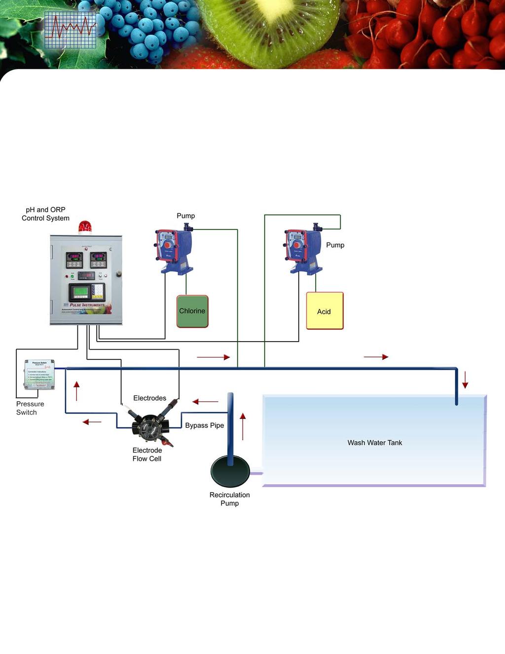
6 1. Overview The System 4 Monitoring and Control System is a state-of-the-art water quality monitoring and control system. It is an essential HACCP tool for wash water automation and control that allows multi-function monitoring, pump control, proportional output and recording. System 4 measures ph, ORP, and Temperature. Each of these components independently senses the current condition of the water and sends a 4-20mA signal back to the central processing unit of the system. In addition, a calculated Free Chlorine value based on clean water is displayed on the touch screen. According to the initial set point levels for the water chemistry, the system will adjust the current water chemistry automatically by turning on chemical dosing pumps. A built-in alarm system alerts to any system or process failure. User-friendly operator interface menu selection provides easy set up and password protected access to set points, timers, and parameter settings. Visit us Online at 3


7 2. System Layout Strobe Light Water Fault Indicator Light ph Monitor Alarm and Control Indicator Lights Touch Screen ORP Monitor Alarm and Control Indicator Lights Temperature Monitor Fig. 1 Automation of Wash Water Sanitation System Diagram Visit us Online at 4
 Audio Alarm Alarm Reset")
 Fig.")
8 Touch Screen Keypad Function Keys Fig. 2 Operator Interface (Touch Screen and Keypad) Audio Alarm Alarm Reset Momentary Switch Emergency Pull / Push Stop Switch Audio Alarm Silence Switch 3-Position Main Power Switch (ON / OFF / Manual) Fig. 3 Right Side of the Control Panel Visit us Online at 5


9 Fig. 4 Bottom of the Control Panel BNC Connectors (Connect ph / ORP Electrodes to connector) Temperature Monitor Touch Screen Fig. 5 Back of the Front Plate inside of the Control Panel Visit us Online at 6


10 Consent Jumper Fig. 6 Consent Inside of the Control Panel Visit us Online at 7
11 3. Specifications Control Panel Range Resolution Accuracy Power Control Panel Dimension Enclosure Rating ph: 0.00 to 14.0 ph ORP: 0 to 1000 mv Chlorine: 0.0 to ppm Temperature: 0.0 to ºF ph: 0.1 ph ORP: 1 mv Chlorine: 0.01 ppm Temperature: 0.1 ºF ph: ± 0.02 ph ORP: ± 1 mv Chlorine: ± 0.1 ppm Temperature: ± 0.2% of FS 110 VAC; 15 Amps Height x Width x Depth: 20 in x 16 in x 13 in NEMA 4X Flow Cell Ports 3 Sensor Ports and 1 Sampling Port Inlet / Outlet Ports 1 1/4 NPT Sensor Ports 1/2 NPT Material PVC SCH 80 Pressure Switch Pressure Adjustable Range Tubing Length Fitting Power 100 psi Max 1.5 to 15 psi 5 feet ¼ NPT 110 VAC Chemical Pump Capacity Variable, See Pump Manual Pressure Variable, See Pump Manual Strokes per Minute 360 Max Turndown Ratio 1800:1 Stroke Length Adjustment 20% to 100% Visit us Online at 8
12 Material IP Rating Power Variable, See Pump Manual IP 65 / IP VAC 3.1 System Components Control Panel ph Electrode ORP Electrode Temperature Flow Cell Pressure Switch Two Chemical Pumps PI1710 PI0020-PH PI0020-ORP THX-011 FC04 PS111 EW, EK, EHE Series 3.2 PLC Inputs and Outputs Pins Input Descriptions Pins Output Descriptions X0 Consent Y0 ph Acid Pump Output X1 -- Y1 -- X2 -- Y2 ORP Oxidation Pump Output X3 -- Y3 -- X4 -- Y4 -- X5 Pressure Switch Y5 -- X6 Alarm Reset Y6 General Visual Alarm X7 -- Y7 General Audio Alarm Y14 Y15 Y17 ph Alarm ORP Alarm Water Fault Channel 1 Channel 2 Channel 3 Channel ma Inputs ph ORP Temperature Visit us Online at 9
13 3.3 Function Keys See Fig. 2 Screen Name Value Set Pt. Timer K Description Displays ph, Free Chlorine, ORP, and Temperature real-time values High and low alarm limits and control set points for ph and ORP Timers for Power ON Delay, Acid Pump ON Too Long, ORP Oxidation Pump ON Too Long, Alarm Delay, and Alarm Reset Offset adjustment for the calculated Free Chlorine Value 3.4 Default Set Points and Timers See section 4.1 for detail descriptions. Setpoints Setpoint Range Adjustable Value (Default) ph Low Alarm 0 14 ph 5.0 ph ph Acid 0 14 ph 6.8 ph ph High Alarm 0 14 ph 9.0 ph ORP Low Alarm mv 400 mv ORP Oxidation mv 670 mv ORP High Alarm mv 900 mv Hysteresis (Dead-Band) ph Low Alarm ph Acid ph High Alarm ORP Low Alarm ORP Oxidation ORP High Alarm Fixed Value 0.1 ph 0.1 ph 0.1 ph 5 mv 5 mv 5 mv Timers Timer Range Adjustable Time (Default) On Delay 0 30 minutes 20 minutes Acid Pump On Too Long 0 30 minutes 20 minutes ORP Oxidation Pump On Too Long 0 30 minutes 20 minutes Alarm Delay 0 5 minutes 1 minute Alarm Reset 0 30 minutes 20 minutes Visit us Online at 10
14 4. Function 4.1 Operation The system 4 provides complete automation of the water disinfection process and chemical treatment with unique capabilities for a Hands Free operation, allowing for true automation 24 hours a day. 14 HH H ph High alarm Acid Pump 1000 HH ORP High alarm Normal Operation Normal Operation L Oxid. Pump LL 0 Low alarm LL 0 Low alarm Fig. 7 ph, and ORPControl Concept ph has three set points: low alarm, acid chemical injection control, and high alarm. ORP also have three set points: low alarm, oxidizer injection control, and high alarm. ph High alarm: turns on above HH Acid pump: turns on above H Low alarm: turns on below LL ORP High alarm: turns on above HH Oxidation pump: turns on below L Low alarm: turns on below LL Visit us Online at 11
15 Hysteresis / dead-band eliminate output chatter at the switch point (See Fig. 8). See section 3.4 for all the hysteresis (dead-band) values. SP = Setpoint Hys = Hysteresis Fig. 8 Hysteresis (Dead-band) 4.2 Monitoring This system monitors ph, ORP, and Temperature. ph is in the range of 0.0 to ORP is in the range of 0 to 1000 mv, and temperature is in the range of 0.0 ºF to ºF using an RTD. The touch screen (See Fig. 2) displays these values. 4.3 Control ph, and ORP Control Under normal conditions, ph is controlled by the system to the desired ph value set through the touch screen by using the function keys and the keypad (see Fig. 2). When the ph rises above the high set point value, the corresponding green indicator light on the front panel (see Fig. 1) will turn ON and the acid pump will automatically turn ON via a control relay. Acid is added to the water until the ph drops down below the set point value, and the acid pump and the corresponding indicator light shut off. Under normal conditions, the ORP oxidation pump is controlled by the system to the desired ORP value set through the touch screen by using the function keys and the keypad (see Fig. 2). When the ORP value drops below the low set point value, the corresponding green indicator light on the front panel (see Fig. 1) will turn ON and the ORP oxidation pump will automatically turn ON via a control relay. The pump will add Chlorine to the water until the ORP rises to the set point value, and then the pump and the corresponding indicator light shut off Proportional Control Proportional control has the ability to increase or decrease the speed of the pump in relation to the set point value by using a 4-20 ma signal. In order to proportionally control the chemical metering pumps for acid and oxidation injection, the chemical metering pumps must be connected to the ON / OFF control outputs and to the 4-20 ma signals from the control panel. The system is able to turn ON or turn OFF the chemical metering pumps to inject chemical at the specified set point values. The 4-20 ma output signals span the ph and ORP scales, ph and mv, respectively. See Section for configuration details Consent The consent function is used to prevent acid and oxidation pumps from running at the same time, which may result in the production of harmful gases (see Fig. 6). Consent also allows for optimized use of chlorine and creates better chemical balance in the water. If the consent jumper is in place, the acid pump takes priority over the oxidation pump. Whenever the acid pump is on, the oxidation pump will never be on, even if the value of the ORP is under the set point. Visit us Online at 12
16 Acid and oxidation pumps will run independently if the consent is off Pressure Switch If a pressure switch is connected and if there is pressure in the recirculation loop, the chemical injection will start treating the water as needed. If no pressure is detected (Water Fault), the control system will continue monitoring, but will not allow for any chemical injection or any alarms to occur. In the Water Fault condition, the alarm function is disabled, and an indicator light flashes ON / OFF. The pressure switch function allows for a 5 second confirmation in order to ignore false signaling or momentary contact Manual Control Turn the power switch located on the side of the control panel to the MAN position (see Fig. 3). The system will bypass the PLC (programmable logic controller) module. The ph, ORP, and Temperature meters (see Fig. 1) will be on to monitor the water condition. The acid and oxidation pumps will be on continuously. Use the manual control function only if the PLC fails. 4.4 Safety Alarm An alarm condition occurs due to process failure when levels of the chemicals exceed the specified alarm limits of alarm set points. Chemical pumps shut off and an audio-visual alarm is activated until reset by an operator Alarm Contact If ph or ORP reaches the alarm set point, either High or Low, the corresponding red alarm indicator light located on the front panel (See Fig. 1) will immediately start flashing, but the chemical pump(s) will continue to feed as needed. If the alarm contact is maintained for at least 2 minutes (default, adjustable, see Section 3.4), the alarm indicator light will continue flashing, the main alarm (strobe light and audio alarm) will turn ON, and all chemical pumps will turn OFF. If the alarm condition restores itself so that the alarm contact is no longer active, then the main alarm will reset itself and normal chemical dosing will be restored Pump On Too Long If the ph or ORP control point is active in the chemical feed mode for more than 20 minutes (default, adjustable, see Section 3.4), the steady corresponding red indicator light and the main alarm (strobe light and audio alarm) will turn ON and will shut OFF all pumps Alarm Silence If there is an alarm, turn the audio alarm switch on the right side of the control panel (See Fig. 3) to the OFF position to silence the alarm. Don t forget to turn ON the Audio Alarm after the problem is fixed Alarm Reset The Alarm Reset momentary switch on the right side of the control panel (See Fig. 3) will reset the main alarm (strobe and audio alarm), and restore the chemical pumps to normal operation for 20 minutes (default, adjustable, see Section 3.4). If the alarm condition continues to exist after set time, the alarm function will start again until the condition is satisfied or reset. Visit us Online at 13
17 4.4.5 Power ON Alarm Delay This feature is activated when the control panel is supplied power (turned ON). A logic mode is activated at power on so that for the first 20 minutes (default, adjustable, see Section 3.4), all alarms are ignored and chemical feed is allowed to occur by the acid and/or oxidation pumps Water Fault If there is a Water Fault, all pumps and alarm functions are disabled, and a Water Fault indicator light on the front of the control panel (See Fig. 1) flashes ON / OFF. 5. Installation Control Panel and Electrodes preferably should be mounted as close to one another as possible and no greater than 50 feet apart (See Fig. 1). 5.1 Control Panel Mounting and Location Mount the Instrument Control Panel on a secure stand, bracket, or wall by the mounting feet provided. Location of the control panel should be determined according to process layout, keeping in mind that it is preferable to locate the control panel in a dry environment, whenever possible, even though it is rated for wet environments at NEMA 4X. The control panel should be accessible for routine maintenance and easy viewing of the front digital display, as well as the visual alarm, and in hearing range of the 80 db audio alarm. It should also be located with enough space underneath of at least three feet for mounting the Injection manifold, along with the switches and cables Electrical and Power The control panel requires 110VAC at 10 Amps. The panel is supplied with a 3-prong grounded plug. Extra attached loads such as valves, mixers, and other such devices should be included in the total electrical requirements. WARNING: To reduce the risk of electrical shock, the control panel must be plugged into a grounded outlet with ratings conforming to the requirements of the control panel, and any other electrical loads connected to it. The panel should be connected to a good ground. DO NOT USE ADAPTERS! All wiring must conform to local electrical codes. 5.2 Terminal Strip Wiring From left to right 1. Acid Pump 2. Oxid. Pump 3. Neutral 4. Ground 5. Pressure Switch 6. Pressure Switch 7. (+) 4-20mA Temperature Recording 8. (-) 4-20mA Temperature Recording 9. (+) 4-20mA ph Recording 10. (-) 4-20mA ph Recording 11. (+) 4-20mA ORP Recording 12. (-) 4-20mA ORP Recording 13. (+) 4-20mA Acid Pump 14. (-) 4-20mA Acid Pump 15. (+) 4-20mA ORP Oxid. Pump 16. (-) 4-20mA ORP Oxid. Pump Terminal strip locations 1-4 are used to power the pumps. Terminal strip locations 5-6 are used for the pressure switch. Terminal strip locations 7-12 are 4-20mA output recording and terminal strip locations are 4-20mA signals to control proportional pumps. (If not used for recording, please do not remove the jumpers.) Visit us Online at 14
 and connect each to their appropriate female BNC connectors on the ph and ORP monitors (see Fig. 5). 5.4 Temperature Controller Connection (6-13, not included) 6 7 8 9 10 11 12 13 14 15 16 1 2 3 4 5 5.")

18 5.3 Sensor Input Connection Bring in the male BNC connectors of the ph and ORP probes through the two large cord grips at the bottom of the control panel (see Fig. 4) and connect each to their appropriate female BNC connectors on the ph and ORP monitors (see Fig. 5). 5.4 Temperature Controller Connection (6-13, not included) Connect J Thermocouple Connect the positive (White wire) of the J Thermocouple to terminal 1 and the negative (Red wire) of the J Thermocouple to terminal 3 on the back of the temperature meter Terminal Description No. Description 1 Positive terminal for thermocouple Negative terminal for thermocouple 4 Power terminal (No polarity) 5 Power terminal (No polarity) (6-13, not included with the default system) 6 Normally closed terminal for Low set point output 7 Common terminal for Low set point output 8 Normally open terminal for Low set point output 9 Common terminal for GO output 10 GO output terminal 11 Normally closed terminal for High set point output 12 Common terminal for High set point output 13 Normally open terminal for Low set point output 14 Common terminal for analog output 15 Current output terminal (4-20 ma) 16 Voltage output terminal (1-5 V, 0-1 V, and 0-10 V) Visit us Online at 15


 to contact inputs (See Section 5.2). 2. Connect tubing to fitting on PS111. 3.")

19 5.5 Pressure Switch Pressure Switch inside the Enclosure PS111 PS111, pressure switch with NEMA 4X, is designed to make a dry contact in the event of a change in the flow followed by a change of pressure. It may be used as a flow switch. The sensitivity of the pressure switch can be adjusted by turning the dial inside of the receptacle (see picture on the right). For high pressure, reduce sensitivity and tighten the dial. For low pressure, increase sensitivity and loosen the dial. PS111 is easy to use and simple to install. Fittings, 5 feet of cable with terminal forks, along with 5 feet of tubing are provided in the package. Connection Instructions: 1. Connect wires (from 5 feet wire cable) to contact inputs (See Section 5.2). 2. Connect tubing to fitting on PS Connect tubing end to the water pipe. 5.6 Flow Cell Flow cell allows water to enter from one end of the flow port and exit the other, while the electrodes take their measurements. Flow Cell Flow Cell Installation The pipe is in a U shape to trap water, so that the electrodes will stay wet. For some electrodes, it is essential that they stay wet at all times. Visit us Online at 16
20 5.7 Chemical Metering Pumps Choose a clean and dry location for the pump, which is close to an electrical outlet and allows for convenient access to stroke length control, frequency control, and tubing connections. Avoid areas where ambient temperature exceeds 122 ºF (50 ºC), fall below 32 ºF (0 ºC), or where the pump or tubing would be exposed to direct sunlight (See the pump manual for details). Flooded Suction Mounting Recommended for liquids that out-gas Shelf Mount Maximum 5 feet suction lift Tank Mount Maximum 5 feet suction lift 6. Monitored Values Touch Screen The default screen on the touch screen is the Value screen (see Fig. 2). This screen will display all the monitored values: ph, ORP, and Temperature. To access this screen press the first Function key labeled Value. If the touch screen is on a screen other than the Value screen, the touch screen will revert back to the default screen in 30 seconds if no buttons are pressed. 7. Configuration / Setup 7.1 Power Up To set up a new unit, first check that the power supply connections are correct, that the outlet is 110VAC, and that the connection and power source are clean of any ground loops, inductive loads or magnetic fields. Shared loads on the same circuit may cause interference. Therefore a clean power circuit is recommended. Also, when using the AC supply, ensure that a 3-way grounded mains lead is used to connect the unit. Pull out the Pull / Push Emergency Stop switch located on the right side of the control panel (see Fig. 3). Switch on the power to the unit via the lighted ON / OFF / Manual switch that is located on the side of the control panel (See Fig. 3). The switch light should turn on the front instrument displays with indicated values on their screen. Visit us Online at 17
21 7.2 Set Points Before we begin operations, we must first define the process parameters. Set the control and alarm set points. See Section 4.1, Fig. 7 for operation concepts and see 3.4 for default set points. 1. Press the Set Pt. Function key on the touch screen (See Fig. 2). Enter the password 2007 using the keypad. 2. Press ph button on the touch screen on the Set Points screen to change the set points for ph. 3. Press the Low Al field on the touch screen to change the Low Alarm set point and enter a value using the keypad and press the Enter button to save. 4. Repeat step 3 to change Acid and High Alarm set points. 5. Repeat Steps 1-4 to change set points for ORP. Press the corresponding button on the Set Points screen to change the set points. 7.3 Timers 1. Press the Timer function button on the touch screen to change the timer values (See Fig. 2). Enter the password 2007 using the keypad. 2. Press the Initial On Delay field to change the value using the keypad and then press the Enter button to save. See section 3.4 for default timer values and ranges. 3. Repeat step 2 to change the Acid On Too Long timer by pressing Acid On Too Long field. 4. Press NEXT button to go to the next timer screen. Change the timer values for Chlorine Oxidation Pump On Too Long and ORP Oxidation Pump On Too Long timers on the second timer screen. Repeat step 2 to change timer values. 5. Repeat step 4 to change Alarm Delay and Alarm Reset timer values on third timer screen. 7.4 Chemical Metering Pump Control EZ Series EW Series EK Series EH Series Priming Normally, the pump should self prime. In order to prime the pump, set the stroke length to 100% and the frequency to 360 strokes per minute (SPM). If the pump is equipped with an air vent valve, open the knob a half turn. Liquid should move up through the suction tubing and into the pump head. When the liquid starts running through the vent side tubing, close the air vent knob and continue with output adjustment (See pump manual for details). Visit us Online at 18
22 If the pump has no air vent valve, disconnect the discharge tubing from the injection valve. When liquid enters the discharge tubing at the pump head, stop the pump, then reconnect the discharge tubing to the injection valve. If the pump does not self prime, remove the check valve housing on the discharge and suction sides to make sure cartridges and gaskets are in correct positions Proportional Control In order to proportionally control the metering pumps for acid and oxidation injection, the chemical metering pumps must be connected to the ON/OFF control outputs and to the 4-20 ma signals from the control panel. The system panel is able to output ON/OFF control functions for metering pumps in order to inject acid and chlorine (controlled by either ORP or chlorine). The 4-20 ma output signals span the ph, Free Chlorine, and ORP scales, ph, mv, and respectively. The set points to control the pumps are entered into the system and the pumps are set to run in external analog-input mode. For example, the set point of the acid pump is entered into the control system at 6.8 ph, which means the acid pump will turn ON above 6.8 ph and turn OFF below 6.8 ph. At 6.8 ph, the control system is outputting ma. Therefore, set the acid pump analog input range to be from ma to 20 ma and set its pumping speed to be from 0 stroke per minute (spm) to its maximum spm, respectively. With this setup, the pumping speed of the acid pump will increase as the ph level gets higher than 6.8 ph and will slow down as it gets close to 6.8 ph. Finally, the pump will turn OFF when the ph value gets below 6.8 ph. Reference: (20-4 ma) / (14-0 ph) x (ph setpoint value) + 4 ma = ma setting of the setpoint Example 6.8 ph: (16 ma) / (14 ph) x (6.8 ph) + 4 ma = ma 6.8 ph = ma = 0 spm 14 ph = 20 ma = maximum spm (360 strokes) ORP works using the same principle, but is set up in the opposite direction. Its set point in the system, for example, is 670 mv. The oxidation pump analog input range would then be from 4 ma to ma (670 mv); then the pump speed range would be from its maximum speed at 4 ma input to 0 spm at ma input. The oxidation pump would then pump at its maximum speed at 0 mv ORP, and slow down as the ORP level gets closer to 670 mv, finally stopping when the level gets above 670 mv. With this setup, the user will be able to control the pump proportionally. Reference: (20-4 ma) / ( mv) x (ORP setpoint value) + 4 ma = ma setting of the setpoint Example 670 mv: (16 ma) / (1000 mv) x (670 mv) + 4 ma = ma 0 mv = 4 ma = maximum spm (360 strokes) 670 mv = ma = 0 spm Visit us Online at 19
23 8. Maintenance 8.1 Electrode Cleaning ph, Free Chlorine, and ORP electrodes are cleaned the same way. Remove the electrodes from the manifold. Take a 1:100 diluted solution of acid to water in a cup, and place the electrode front tip in the solution at least two inches deep, for a minimum of five to fifteen minutes. Rinse the tip and re-check the calibration. 8.2 Calibration ph Calibration 1. Place the ph probe in buffer solution 7.00 and allow sufficient time for the electrode to reach the buffer solution value. 2. Press and hold the CAL button for three seconds to initialize the calibration process. 3. The CAL indicator light will turn on and the top display will start blinking. The second display will show 4-7 for a few seconds. 4. The controller will automatically calibrate to the buffer solution value (ph 7.00). The first and second display will stop blinking after the controller is calibrated to ph The second display will show - 7. Visit us Online at 20


.")
24 5. Rinse the electrode with water and place it in the ph 4.01 buffer solution and allow sufficient time for the electrode to reach the buffer solution value. 6. Press the ENT button. 7. The first display will start blinking and it will not stop blinking until the controller is calibrated to the buffer solution value (ph 4.01). The second display will show Press ENT to save all calibration values. Follow the same steps if you are using ph and ph 7.00 buffer solution ORP Calibration 1. Place the ORP electrode into a known ORP standard solution (ORP-468). Press and hold the CAL button for three seconds. 2. Press the AUTO button if the ORP value is already at the standard solution value (468). Press the ENT button to start the calibration if the ORP value is NOT the standard solution value. The CAL indicator light will turn on and the SCAL on the second display will start blinking. Visit us Online at 21

. 8.")

25 3. Use the UP and DOWN arrow to adjust the ORP calibration value to match the known standard solution value (468). 4. Press ENT to save the calibration value. 8.3 Chemical Metering Pump WARNING: Always wear protective clothing, face shield, safety glasses and gloves when performing any maintenance or replacement on your pump. Periodically check the chemical tank level to prevent the pump from operating without liquid. Check the pump operating condition at least every 6 months: pump head position, screws, bolts, and seals. Check more frequently if using an aggressive chemical. Also, clean the hydraulic parts, such as valves and filter, as often as needed. (See pump manual for details). 8.4 Surge Suppressor A surge suppressor is used to protect the control panel to prevent damage from loads voltage surges, spikes, and electrical line noise. The green LED on the surge suppressor indicates that the surge suppressor is working. If the green LED is off, this indicates that power is not being supplied to the surge suppressor. In addition, the LED will not illuminate if there has been a utility power failure or a short circuit. Periodically check the surge suppressor to ensure reliable system performance. Visit us Online at 22

26 9. Troubleshooting Guides Alarm is an indication of malfunction. An alarm occurs when the ph and ORP values deviate beyond the alarm range set on the operator interface, or if it takes greater then thirty minutes to adjust the water chemistry. In the alarm mode, the strobe light is on and so is the audio horn (unless it has been turned to silence position). The chemical feed mode is immediately interrupted until the RESET button is pushed which reactivates normal operation. 9.1 Control system failed If the control system failed to work, such as pumps are not pumping when they are supposed to, you can reset the PLC to fix this problem. If resetting the PLC does not fix the problem, please contact the factory. To reset the PLC located on the back plate inside the control panel, toggle the switch to STOP (to the right), then to RUN (to the left without stopping in the middle). Finally, position the toggle switch to TERM (to the middle). 9.2 Sensor Failed Unscrew the sensors from the threaded holder and place in known calibration standards. Place the ph probe in ph 7.00 and 4.00 solutions. Place the ORP probe in 468 mv solution. The readings on the control panel should match or should be close. Follow calibration procedure. If sensors are too far off the standard readings, follow maintenance procedure as described in Section Sensor Cable is Damaged Follow the sensor cable carefully along its length and check for any cuts, breaks, or tight kinks. If the cable is damaged, replace the sensor. 9.4 Sensors Need Maintenance If other parameters seem normal but the readings seem abnormal in calibration standards, service the sensors. Take a 1:100 diluted solution of acid to water in a cup and place the sensor front tip in the solution at least 2 inches deep for a minimum of five to fifteen minutes. Follow section 8.2 for calibration. Visit us Online at 23
27 9.5 ph / ORP Monitor Error Message The monitor s error messages are displayed on the second screen of the controller (see Fig. 1). Error Code Explanation Solution E-oF E-uF E-C1 E-C2 ph / ORP value is over the high limit. ph value is higher than 15.0 ph. ORP value is higher than 1501 mv. ph / ORP value is below the low limit. ph value is lower than 1.0 ph. ORP value is lower than mv. Electrode needs cleaning. Old standard calibration solution. Big discrepancy between the displayed value and the standard calibration solution value. E-C3 Incorrect standard calibration solution. E-t1 No temperature compensation. Check electrode connection and cable. Check the solution. Check electrode connection and cable. Check the solution. See Section 8.1 for electrode cleaning instructions. Change calibration solution. Change electrode. See Section 8.1 for electrode cleaning instructions. Change calibration solution. Change electrode. Change calibration solution. Make sure the calibration solution is ph 4, 7, or 10. Temperature sensor or resistor is missing on controller terminal 11 and 12. Replace resistor or electrode. E-t2 E-t3 E-t4 E-S1 E-S2 No temperature compensation. There is a short circuit. Temperature is over the high limit. Temperature is higher than 110ºC. Temperature is below the low limit. Temperature is lower than -10ºC. Controller system error. Loss of memory. Controller system error. Defective A/D converter. Temperature sensor or resistor is short circuit on controller terminal 11 and 12. Replace resistor or electrode. Temperature sensor or resistor connection on controller terminal 11 and 12. Do not use electrode over the temperature limit. Temperature sensor or resistor connection on controller terminal 11 and 12. Do not use electrode over the temperature limit. Contact the factory. Contact the factory. Visit us Online at 24
28 9.6 Chemical Pump Failed Reset the control panel. If the pump receptacle has 110VAC output, but the pump is not turning on, check to make sure the pump is in the on position and at least 50% stroke and frequency. If the pump still does not turn on, the pump has failed and need service. 10 Contact Phone: (818) Web: Visit us Online at 25
User Manual System 11
 User Manual System 11 www.pulseinstrument.com Copyright 2007 Pulse Instruments All Rights Reserved 943 Flynn Road, Camarillo, CA 93012 Phone: (800) 462-1926 Fax: (800) 878-9172 SYSTEM 11 Water Disinfection
Operator's Manual Dielman Rock Island Industrial Dr. St. Louis, MO Tel:(314)
") Operator's Manual TABLE OF CONTENTS Firmware Version... 1 Environmental Conditions... 1 Electrical Specifications... 1 Warnings... 2 Section A: Programming the Controller... 3 A 1: Adjusting the Display
Operator's Manual TABLE OF CONTENTS Firmware Version... 1 Environmental Conditions... 1 Electrical Specifications... 1 Warnings... 2 Section A: Programming the Controller... 3 A 1: Adjusting the Display
ORP (mv) Controller Model: ORP-XP2. UP DOWN ENTER Time & Date Main Menu Alarm Reset
 Controller Model: ORP-XP2. UP DOWN ENTER Time & Date Main Menu Alarm Reset") Instruction Manual ORP (mv) Controller Model: ORP-XP2 Power Control Alarm Comms UP DOWN ENTER Time & Date Main Menu Alarm Reset Supplied by: Convergent Water Controls Pty Ltd 2/4 Huntley Street, PO Box
Instruction Manual ORP (mv) Controller Model: ORP-XP2 Power Control Alarm Comms UP DOWN ENTER Time & Date Main Menu Alarm Reset Supplied by: Convergent Water Controls Pty Ltd 2/4 Huntley Street, PO Box
Owner s Manual RD432-0 Chemical Controller
 Owner s Manual RD432-0 Chemical Controller Table of Contents I. Introduction page 2 A. Water Chemistry page 2 B. Safety page 3 C. System Components page 4 D. Specifications page 7 E. Controller Panel Descriptions
Digi-Sense TC9000 Advanced PID and On/Off Temperature Controller with Thermocouple Input
 User Manual 99 Washington Street Melrose, MA 02176 Phone 781-665-1400 Toll Free 1-800-517-8431 Visit us at www.testequipmentdepot.com Digi-Sense TC9000 Advanced PID and On/Off Temperature Controller with
Tempco PCT-3000 Series Temperature Control Console with Relay Output for Heating or Cooling Applications
 Instruction Manual Tempco PCT-3000 Series Temperature Control Console with Relay Output for Heating or Cooling Applications Manual PCT-3000 Revision 9/2014 The PCT-3000 series control console incorporates
CELLTROL II BIOREACTOR CONTROL SYSTEM OPERATIONS MANUAL
 Operation Manual Celltrol II Bioreactor Control System Page 1 of 33 Table of Contents 1) Introduction... 3 1.1) Scope of Document... 3 1.2) Control System Overview... 3 1.3) Introduction to Celltrol II...
Tempco Part Number PCT30006 Temperature Control Enclosure with Relay Output for Tote Tank Heating Applications
 Instruction Manual Tempco Part Number PCT30006 Temperature Control Enclosure with Relay Output for Tote Tank Heating Applications Manual PCT30006, Revision 9/20/2016 The PCT30006 control enclosure incorporates
VERTEX VT10 SERIES PID OPERATION MANUAL MICROPROCESSOR BASED PID CONTROLLER
 1 VERTEX VT10 SERIES PID OPERATION MANUAL MICROPROCESSOR BASED PID CONTROLLER 1. INTRODUCTION This manual contains information for the installation and operation and tuning of our Vertex VT10 series self-tuning
INSTALLATION & USER MANUAL
 INSTALLATION & USER MANUAL HC Digital Automatic Humidistat (Y3760) CONTROLS 506808-01 3/2016 Supersedes 6/2011 picture goes here THIS MANUAL MUST BE LEFT WITH THE HOMEOWNER FOR FUTURE REFERENCE NOTICE
User s Manual. TIGER S EYE E-Series Mark V Jockey. TIGERFLOW Systems, Inc Mint Way Dallas, Texas
 User s Manual TIGER S EYE E-Series Mark V Jockey TIGERFLOW Systems, Inc. 4034 Mint Way Dallas, Texas 75237 214-337-8780 www.tigerflow.com TABLE OF CONTENTS Introduction... 4 Sequence of Operation... 5
Universal Gas Detector
 Universal Gas Detector Instruction Manual PureAire Monitoring Systems, Inc. 557 Capital Drive Lake Zurich, Illinois 60047 Phone: 847-726-6000 Fax: 847-726-6051 Toll-Free: 888-788-8050 pureairemonitoring.com
M790 ph/orp Controller. Owner s Manual
 M790 ph/orp Controller Owner s Manual Table of Contents I. Introduction page 2 A. Water Chemistry page 2 B. Safety page 3 C. System Components page 4 D. Specifications page 7 E. Controller Panel Descriptions
STRANTROL SYSTEM7 MECHANICAL ROOM CONTROLLER INSTALLATION, OPERATION & MAINTENANCE MANUAL
 STRANTROL SYSTEM7 MECHANICAL ROOM CONTROLLER INSTALLATION, OPERATION & MAINTENANCE MANUAL Table of Contents Section Page Introduction... 1 Installation... 3 Plumbing... 11 Electrical... 13 Programming...
User Manual. Digi-Sense TC9500 Advanced Multiparameter Temperature Controller with Thermocouple, Thermistor, and RTD Inputs
 User Manual Digi-Sense TC9500 Advanced Multiparameter Temperature Controller with Thermocouple, Thermistor, and RTD Inputs Models 89800-03 and 89800-04 THE STANDARD IN PRECISION MEASUREMENT Table of Contents
M770 ph Controller Owner s Manual
 M770 ph Controller Owner s Manual Table of Contents I. Introduction page 2 A. Water Chemistry page 2 B. Safety page 3 C. System Components page 4 D. Specifications page 7 E. Controller Panel Descriptions
IMPORTANT SAFETY INSTRUCTIONS READ AND FOLLOW ALL INSTRUCTIONS SAVE THESE INSTRUCTIONS
 Operating Manual MODEL RC554P AND 554200 ph Digital Controller FEED ph FLOW ALERT AUTO MODE SET LEVEL FEED TIME ph CALIB FLOW SWITCH ph ph OUTPUT POWER IMPORTANT SAFETY INSTRUCTIONS READ AND FOLLOW ALL
F PC and AO OUTPUT BOARDS INSTRUCTION MANUAL. Blue-White. Industries, Ltd.
 F-2000 PC and AO OUTPUT BOARDS INSTRUCTION MANUAL Blue-White R Industries, Ltd. 500 Business Drive Huntington Beach, CA 92649 USA Phone: 714-89-8529 FAX: 714-894-9492 E mail: sales@blue-white.com or techsupport@blue-white.com
Nitrogen Dioxide (NO2) Single-Point Gas Detection System
 Single-Point Gas Detection System") Nitrogen Dioxide (NO) Single-Point Gas Detection System DESCRIPTION Wall-mounted gas monitor with built-in nitrogen dioxide (NO)/diesel fume gas sensor, accepts one analog remote device such as a secondary
Nitrogen Dioxide (NO) Single-Point Gas Detection System DESCRIPTION Wall-mounted gas monitor with built-in nitrogen dioxide (NO)/diesel fume gas sensor, accepts one analog remote device such as a secondary
Analog Room Pressure Monitor RPC Series
 Description The Room Pressure Monitor is used to measure differential pressure in the range of 0.125 to 1"wc or 30 to 250 Pa. It combines precision high sensitivity silicon sensing capabilities and the
Carbon Monoxide Transmitter
 Introduction The CO Transmitter uses an electrochemical sensor to monitor the carbon monoxide level and outputs a field-selectable 4-20 ma or voltage signal. The voltage signal may also be set to 0-5 or
AutomationDirect PM24. Microprocessor - Based Process/Temperature Limit Controller. Operator s Manual. Technical Support.
 AutomationDirect 1/16 DIN Series Technical Support We strive to make our manuals the best in the industry. We rely on your feedback to let us know if we are reaching our goal. If you cannot find the solution
Installation, Operation & Maintenance Manual. Wash System
 Installation, Operation & Maintenance Manual Wash System Kleen Flo Wash System Installation, Operation & Maintenance Manual CONTENTS Introduction and Overview... 3 Pipeline Wash System Features... 5 Wash
M820 ph/dual ORP Controller. Owner s Manual
 M820 ph/dual ORP Controller Owner s Manual Table of Contents I. Introduction page 2 A. Water Chemistry page 2 B. Safety page 3 C. System Components page 4 D. Specifications page 7 E. Controller Panel Descriptions
1 4 DIN Dissolved Oxygen Controller
 16. Warranty OAKTON warrants this controller to be free from significant deviations in material and workmanship for a period of one year from date of purchase. If repair or adjustment is necessary and
ModSync Sequencing System Installation & Operation Manual. For use with Fulton Steam Boilers.
 ModSync Sequencing System Installation & Operation Manual For use with Fulton Steam Boilers. Revision 3.0 8/21/2008 - 2 - Table of Contents Introduction Page 4 Features Page 4 Sequence of Operation Page
Operation and Maintenance Manual
 Warnings... 1 General Guidelines... 1 Firmware Version... 1 Environmental Conditions... 2 Electrical Specifications... 2 NSF Suggested Operation Ranges... 3 Applicable Sensor Operating Ranges... 3 Section
Operation and Maintenance Manual
 Warnings... 1 General Guidelines... 2 Firmware Version... 2 Environmental Conditions... 2 Electrical Specifications... 2 NSF Suggested Operation Ranges... 3 Applicable Sensor Operation Ranges... 3 Section
Oxygen (O2) Single-Point Gas Detection System
 Single-Point Gas Detection System") Oxygen (O) Single-Point Gas Detection System DESCRIPTION Wall-mounted gas monitor with built-in oxygen (O) sensor, accepts one analog remote device such as a secondary gas sensor, temperature or humidity
Oxygen (O) Single-Point Gas Detection System DESCRIPTION Wall-mounted gas monitor with built-in oxygen (O) sensor, accepts one analog remote device such as a secondary gas sensor, temperature or humidity
IMPORTANT SAFETY INSTRUCTIONS READ AND FOLLOW ALL INSTRUCTIONS SAVE THESE INSTRUCTIONS
 Operating Manual MODELS RC554XP AND 554000 ORP/pH Digital Controller FEED ph ALERT FEED ORP ALERT F LOW ph MODE AUTO FEED ONCE SET LEVEL FEED TIME HI LOW ph CALIB ORP ph ORP IMPORTANT SAFETY INSTRUCTIONS
Phone-A-Stat. MODEL Command Center With Thermostat Operation, Maintenance & Installation Manual. Introduction.
 Introduction The UL listed Phone-A-Stat (model # 7632 ) is designed and approved for the safe operation of remotely controlling four independent loads, such as a sprinkler system or a water heater via
Powell. Fabrication & Manufacturing Inc. Hypo Batch Controller with Temperature Indicator (Digital ORP/ORP/Temperature System) 2400 Series
 2400 Series") Powell Fabrication & Manufacturing Inc Hypo Batch Controller with Temperature Indicator (Digital ORP/ORP/Temperature System) 2400 Series Introduction A sodium hypochlorite batch controller has been designed
Powell Fabrication & Manufacturing Inc Hypo Batch Controller with Temperature Indicator (Digital ORP/ORP/Temperature System) 2400 Series Introduction A sodium hypochlorite batch controller has been designed
MODEL ORP/pH Digital Controller
 MODEL 554000 ORP/pH Digital Controller Operating Manual Rola-Chem Digital Controller PN 554102 6/01/2012 Page: 1 of 20 QUICK START REFERENCE Use this section for reference - please read all safety instructions
Pump-Down Controller MODEL 4052
 Pump-Down Controller 4-20mA Input/Scalable Output Seal Fail Monitoring Duplex Pump Alternation Hand-Off-Auto Controls Dual Run-time Meters RS-485/Modbus Communications DESCRIPTION The Model 4052 Pump-Down
Rev B, 9/2/2009. Kodiak Chiller Overview
 930-0001 Rev B, 9/2/2009 Kodiak Chiller Overview Presentation Outline Phone: 781-933-7300 Lytron Technical Support Contact Information 3 Introduction 4 Part I: Unpacking 5 Part II: Installation 7 Part
IMPORTANT SAFETY INSTRUCTIONS READ AND FOLLOW ALL INSTRUCTIONS SAVE THESE INSTRUCTIONS
 Operating Manual MODEL RC554X AND 554230 ORP Digital Controller FEED ALERT ORP FLOW AUTO MODE SET LEVEL FEED TIME FLOW SWITCH ORP ORP OUTPUT POWER IMPORTANT SAFETY INSTRUCTIONS READ AND FOLLOW ALL INSTRUCTIONS
Remote Display Alarm Indicator for Oxygen monitor
 Remote Display Alarm Indicator for Oxygen monitor (Part number 99091) The Remote Display Alarm Indicator is designed to display remote oxygen concentration information from PureAire oxygen monitors. All
Corporate Profile. needs and product demands. CON 08X /03 Rev 0
 Corporate Profile A leader in the field of electrochemical instrumentation, Eutech Instruments is a dynamic company rapidly positioning itself globally as a leading manufacturer of electrochemical instrumentation
B-40/B-41 Modulating Temperature Controller
 INSTALLATION & OPERATING INSTRUCTIONS B-40/B-41 Modulating Temperature Controller For Raytherm Boilers & Water Heaters H2 514-4001 WH2 2100-4001 Catalog No. 5000.70 Effective: 12-21-11 Replaces: NEW P/N
Temperature Controllers
 Model TEC-4100 1/4 DIN Model TEC-4100 1/4 DIN Temperature Controller Ordering Code: Power Input BOX 1 4 = 90-250 VAC 5 = 11-26 VAC / VDC TEC-4100- Configurable for 4 Programmable Outputs and NEMA 4X/IP65
Pump-Up Controller MODEL 4062
 Pump-Up Controller 4-20mA Input/Scalable Output Seal Fail Monitoring Duplex Pump Alternation Hand-Off-Auto Controls Dual Run-time Meters RS-485/Modbus Communications DESCRIPTION The Model 4062 Pump-Up
Water Technologies. Strantrol System 3i. Technical Guide
 Water Technologies Strantrol System 3i Technical Guide Table of Contents Warning Notifications...i Mounting Chapter 1...1 1.1 Environmental Conditions...1 Plumbing Chapter 2...3 2.1 Sample Stream General
SERIES 101T MOISTURE ANALYZER QUICK START GUIDE
 SERIES 101T MOISTURE ANALYZER QUICK START GUIDE INSTALLATION The moisture probe may be installed directly into the sample stream through a ½ inch NPT adapter (See Fig. 1). The penetration into the sample
STRANTROL SET POINT CONTROLLER INSTALLATION, OPERATION & MAINTENANCE MANUAL
 STRANTROL SET POINT CONTROLLER INSTALLATION, OPERATION & MAINTENANCE MANUAL Table of Contents General Guidelines... i Warning Notifications...ii Mounting/Plumbing...1 Mounting the Controller...1 Wrapping
F4 Process Controller Installation and Operation Guide
 F4 Process Controller Installation and Operation Guide 1.Introduction 1.1.Highlight Features Space saving, only 55mm panel depth required Higher sampling rate (1mS) results in better control performance
DE20 INSTRUCTION MANUAL
 DE20 INSTRUCTION MANUAL Now UL Listed! SET POINT DE20 SET YOUR DISTRIBUTOR: Chemical Distributors, Inc. 80 Metcalfe Street - Buffalo, NY 14206 Phone: 800-777-2436 716-856-2300 Fax: 716-856-7115 sales@cdibuffalo.com
Two-Channel Gas Controller
 Two-Channel Gas Controller Specifications subject to change without notice. USA 09 Page of DESCRIPTION Highly configurable, UL 0 performance-tested and -certified, and wall-mounted gas monitor; continuously
eed quality electronic design USER s MANUAL
 eed quality electronic design www.dem-it.com eed www.qeed.it info@qeed.it ANALOG SIGNAL DISPLAY Q-DISP-T USER s MANUAL The displays Q-DISP-T, prepared for mounting on the back panel, 96x48mm, will allow
203RE ph v 1.0 Instructions
 203RE ph v 1.0 Instructions \\Elmacron-server\gemensam\Instruktioner\Instruktioner i Word\203RE\Engelska\203 RE ph_eng.doc TABLE OF CONTENTS INTRODUCTION... 2 DEFAULT SETTINGS... 2 INSTALLATION... 3 Casing...
Duct and Rough Service Carbon Monoxide Sensor
 Product Identification and Overview Duct and Rough Service Carbon Monoxide Sensor BAPI s Carbon Monoxide Sensor offers enhanced electrochemical sensing with outstanding accuracy at low concentrations.
User Manual. Digi-Sense TC9600 Advanced Multiparameter Temperature Controller with Thermocouple, Thermistor, and RTD Inputs
 User Manual Digi-Sense TC9600 Advanced Multiparameter Temperature Controller with Thermocouple, Thermistor, and RTD Inputs Models 89800-13 and 89800-14 THE STANDARD IN PRECISION MEASUREMENT Table of Contents
Product waste disposal - Protection of the environment:
 Product waste disposal - Protection of the environment: In accordance with the provisions of the Waste Electrical and Electronic Equipment (WEEE - 2002/ 96/ EC) Directive, used electric and electronic
ph COOLING TOWER CONTROLLER
 LAKEWOOD INSTRUMENTS MODEL 350 ph COOLING TOWER CONTROLLER INSTRUCTION MANUAL SERIAL #: Lakewood Instruments 7838 North Faulkner Road, Milwaukee, WI 53224 USA Phone (800) 228-0839 Fax (414) 355-3508 http://www.lakewoodinstruments.com
Table of Contents SECTION PAGE
 Table of Contents SECTION PAGE SECTION 1 INTRODUCTION................... 1.1 Description.............................. 1.2 Features................................ 1.3 Models.................................
Contents. Outline of Product. Features of Product. Specifications of Product. Name and central function of section. Illustration of Terminal
 DA-750 1 page Contents Outline of Product 3 page Features of Product 3 page Specifications of Product 4 page Name and central function of section 5 page Illustration of Terminal 8 page Setting of Menu
OVEN INDUSTRIES, INC.
 OVEN INDUSTRIES, INC. OPERATING MANUAL Model 5C7-252 TEMPERATURE CONTROLLER With PLC Inputs Introduction Thank you for purchasing our controller. The Model 5C7-252 is an exceptionally versatile unit and
SPECIFICATION MODEL 5200 GAS MONITOR SYSTEM. User Instructions For The Model 5200 Gas Monitor System
 SPECIFICATION MODEL 5200 GAS MONITOR SYSTEM User Instructions For The Model 5200 Gas Monitor System To completely customize the specifications to your exact application, modifications to the following
KONTROL INVIKTA Double
 KONTROL INVIKTA Double PACK CONTENTS A) "Basic POOL Double" ph and REDOX control device B) PVC Crystal 4x6 with suction device (2 m) C) Polyethylene delivery hose (3m) D) Attachment screw (=6 mm) E) Foot
DCM200 Aquatics Controller. Keypad Navigation
 DCM200 Aquatics Controller Pool 750 mv 7.49 ph 81.1F Keypad Navigation BACK Button. In navigation screens, used to go back 1 level. NOTE: In Output Status Screens 1-9, BACK is used to change output HOA
Centro-Matic Automated Lubrication Systems System Controls
 Selecting the right controls for your automated lubrication system is one of the last steps in the design process. Several different models may be chosen to control power-operated pumps, depending on the
D3000. Installation & Setup Guide
 Page 1 of 15 17483-00 Rev B s1 April 2009 Contents Description Page Safety... 3 Installation Standards 3 Specification. 3-4 Circuit Board Connection 5 Mounting Dimensions 6 Installation Procedure 6 Mechanical
JENCO ELECTRONICS, LTD. MANUFACTURER OF PRECISION INSTRUMENTS
 OPERATION MANUAL THE JENCO MODELS 3672, 3673, 3675 1/4 DIN ph/orp CONTROLLER JENCO ELECTRONICS, LTD. MANUFACTURER OF PRECISION INSTRUMENTS INTENDED USE AND GENERAL INTRODUCTION The models 3672, 3673 and
SMART Gas Detector/Transmitter(4~20mA) with built-in LCD & explosion proof DA-500
 with built-in LCD & explosion proof DA-500") SMART Gas Detector/Transmitter(4~20mA) with built-in LCD & explosion proof DA-500 C-910C, Bupyeong Woolim Lion s Valley, #425, Cheongcheon-Dong, Bupyeong-Gu, Incheon, Korea TEL: +82-32-623-7507 FAX: +82-32-623-7510
SMART Gas Detector/Transmitter(4~20mA) with built-in LCD & explosion proof DA-500 C-910C, Bupyeong Woolim Lion s Valley, #425, Cheongcheon-Dong, Bupyeong-Gu, Incheon, Korea TEL: +82-32-623-7507 FAX: +82-32-623-7510
MICROtrac MICROPROCESSOR BASED WATER TREATMENT CONTROLLER. Installation and Operation Manual REV. L
 MICROtrac MICROPROCESSOR BASED WATER TREATMENT CONTROLLER Installation and Operation Manual MICROtrac Warranty Pulsafeeder, Inc. warrants MICROtrac control systems (including the conductivity sensor) of
Beacon 200 Gas Monitor Operator s Manual. Part Number: RK Released: 6/6/08
 Beacon 200 Gas Monitor Operator s Manual Part Number: 71-2102RK Released: 6/6/08 Table of Contents Chapter 1: Introduction.................................................3 Overview.............................................................3
Software Version 2.01 LEVEL MONITOR MODEL 220
 Software Version 2.01 LEVEL MONITOR MODEL 220 19 April 2000 CONTENTS 1. Introduction 1 1.1 Model Number Designation 2 1.2 Intrinsic Safety Considerations 3 2. Specification 4 3. Operation 6 3.1 Display
Refrigeration Controller Operator s Manual (HRC) PO Box 6183 Kennewick, WA
 PO Box 6183 Kennewick, WA") Refrigeration Controller Operator s Manual (HRC) PO Box 6183 Kennewick, WA 99336 www.jmcvr.com 1-509-586-9893 Table of Contents TABLE OF FIGURES...1 OVERVIEW OF THE HRC CAPABILITIES...2 INSTALLATION AND
Refrigeration Controller Operator s Manual (HRC) PO Box 6183 Kennewick, WA 99336 www.jmcvr.com 1-509-586-9893 Table of Contents TABLE OF FIGURES...1 OVERVIEW OF THE HRC CAPABILITIES...2 INSTALLATION AND
EKC 347 Liquid Level Controller REFRIGERATION AND AIR CONDITIONING. Manual
 EKC 347 Liquid Level Controller REFRIGERATION AND AIR CONDITIONING Manual Contents Introduction...3 Valve compatibility...3 Features...3 Application examples...3 Ordering...3 Operating the EKC 347...4-5
ANALOX SENSOR TECHNOLOGY LTD ANALOX DD1101 INSTALLATION & OPERATION MANUAL
 ANALOX SENSOR TECHNOLOGY LTD ANALOX DD1101 INSTALLATION & OPERATION MANUAL SAFETY WARNING Please Refer to the Safety Warning in Section 7.1 regarding the chemicals in the oxygen sensor Analox Sensor Technology
Snifter ATEX22 VERSION. User Manual. Distributor
 Snifter ATEX22 VERSION User Manual Distributor Version 1.4 09/09/2009 Table of Contents 1. INTRODUCTION... 3 1.1. Safety... 3 1.2. Product overview... 4 1.3. How does it work?... 4 2. INSTALLATION... 5
TC515 and TC600 Installation Manual. a Winters company
 THERMOLINE TEMPERATURE CONTROLLERS TC515 and TC600 Installation Manual a Winters company Guarantee 12 months Congratulations on the purchase of this new product. Special care with the design, workmanship
GLD-30 Gas Leak Detector
 GLD-30 Gas Leak Detector Installation, Operation & Maintenance General: The Archer Instruments GLD-30 is an ambient air monitor, used to detect the presence of a target gas (or gases) and to alert operators
PROCESS & TEMPERATURE UNIVERSAL INPUT DIGITAL METERS
 PROCESS & TEMPERATURE UNIVERSAL INPUT DIGITAL METERS NOVA PD56 Series Thermocouple, RTD, & Process Inputs Universal Power Supply 1-24 VAC Up to 3 Alarm Relays Retransmitting 4-2 ma Output Input Max/Min
IMR 5000 IMR 400. CEMS Operating Manual IMR USA S/N: Sample IMR Sensors Inside IMR 400. Gas Dryer Inside. IMR Environmental Equipment Inc.
 CEMS Operating Manual IMR USA S/N: Sample IMR 5000 IMR 400 IMR 400 IMR 5000 Measure MESURE PURGE Purge CALIBRATE Calibrate OFF OFF RESET Measure ON ON Calibrate RESET PUMP Gas Dryer Inside PUMP Sensors
JDDT1 - Single Stage Digital Thermostat
 JDDT1 - Single Stage Digital Thermostat CAUTION NOTICE: The thermostat must be installed by authorized professionals. It should be located in a place free of vibrations, impacts, and corrosive gases. SET
I/A Series 716C 1/16 DIN Temperature Controller
 Product Specifications I/A Series 716C 1/16 DIN Temperature Controller PSS 2C-1B5 A The Foxboro 716C is a powerful compact, 1/16 DIN, microprocessor-based temperature controller that offers a variety of
Process & TeMPerATUre UniversAl input DigiTAl MeTers
 Process & TeMPerATUre UniversAl input DigiTAl MeTers nova PD56 series Thermocouple, rtd, & Process inputs Universal Power supply 1-24 va c Up to 3 Alarm relays retransmitting 4-2 ma output input Max/Min
TCA-9102 Series Surface Mount Temperature Controllers with High and Low Alarm
 TCA-9102 Series Surface Mount Temperature Controllers with High and Low Alarm General Description & Applications The TCA-9102 Series Temperature Controller with Alarm offers a versatile solution for a
DNC-PS700-A10 Differential Pressure Control Meter. Operation and Installation Manual
 DNC-PS700-A10 Differential Pressure Control Meter Operation and Installation Manual NationalControlsCorp. Phone 800-323-2593 Fax 630-231-1377 www.nationalcontrols.com MII-PS700-011 N ationalc o ntro ls
Interchangeable thermistor (THE types) Output Contact E5CS-R1KJX-F E5CS-R1PX-F E5CS-R1GX-F Voltage E5CS-Q1KJX-F E5CS-Q1PX-F E5CS-Q1GX-F
 Output Contact E5CS-R1KJX-F E5CS-R1PX-F E5CS-R1GX-F Voltage E5CS-Q1KJX-F E5CS-Q1PX-F E5CS-Q1GX-F") Temperature Controller 1/16 DIN Sized Controller Offers Selectable Control, Alarm Modes Accurate to ±0.5% of full scale Multiple temperature scale ranges allow flexibility to match application Field-selectable
Temperature Controller 1/16 DIN Sized Controller Offers Selectable Control, Alarm Modes Accurate to ±0.5% of full scale Multiple temperature scale ranges allow flexibility to match application Field-selectable
ORP/MILLIVOLT CONTROLLER
 LAKEWOOD INSTRUMENTS MODEL 330 ORP/MILLIVOLT CONTROLLER INSTALLATION & OPERATION MANUAL SERIAL #: Lakewood Instruments 7838 North Faulkner Road, Milwaukee, Wisconsin 53224 USA Phone (800) 228-0839 Fax
Use this Specification Template to develop a specification to be used for requesting a quote or defining a job work description.
 Use this Specification Template to develop a specification to be used for requesting a quote or defining a job work description. This document is a framework for creating a specification. It may contain
CA5000 Liquid CO 2 Freezer Backup System
 CA5000 Liquid CO 2 Freezer Backup System OPERATING INSTRUCTIONS MANUAL HAMPSHIRE CONTROLS CORPORATION ONE GROVE STREET / P.O. BOX 516, DOVER, NEW HAMPSHIRE USA 03821 TEL. (603) 749-9424 FAX (603) 749-9433
Pipe Freeze Protection Control SCFP-CO-F130 Installation and Operation Manual
 MANUAL Pipe Freeze Protection Control SCFP-CO-F130 Installation and Operation Manual Model FPT 130 Single Point Freeze Protection Heat Trace Control Table of Contents SCFP-CO-F130 Overview... 3 Installation...
HALOGUARD IR MULTI-POINT, COMPOUND SPECIFIC MONITOR INSTRUCTION MANUAL
 HALOGUARD IR MULTI-POINT, COMPOUND SPECIFIC MONITOR INSTRUCTION MANUAL S E R I A L N O. M O D E L N O. T e m p. R a n g e 1 - = > 6 0 o F 2 - = 4 0-6 0 o F 3 - = < 4 0 o F - G a s T y p e 1 - R -1 1 2
PF1000 CONTROLLER. for the. Heateflex Corporation 405 E. Santa Clara St. Arcadia, CA TEL: (626) ; FAX: (626)
 ; FAX: (626)") PF1000 CONTROLLER for the AQUARIUS I/II DEIONIZED WATER HEATING SYSTEM Heateflex Corporation 405 E. Santa Clara St. TEL: (626)599-8566; FAX: (626)599-9567 Rev. 07 10/19/10, (PF1000) 1 2 TABLE OF CONTENTS
PF1000 CONTROLLER for the AQUARIUS I/II DEIONIZED WATER HEATING SYSTEM Heateflex Corporation 405 E. Santa Clara St. TEL: (626)599-8566; FAX: (626)599-9567 Rev. 07 10/19/10, (PF1000) 1 2 TABLE OF CONTENTS
Model Q45P/R. ph/orp Monitor...
 Model Q45P/R ph/orp Monitor... Sensor Mounting Configurations The Differential Difference ORP Monitor ATI's versatile Q45P/R ph/orp system is designed for use in all industrial and municipal applications.
Pioneer-R16 Gas Monitor Operator s Manual
 Pioneer-R16 Gas Monitor Operator s Manual Edition 7/2/97 RKI INSTRUMENTS, INC RKI Instruments, Inc. 33248 Central Ave, Union City, CA 94587 (510) 441-5656 Chapter 1: Description About the Pioneer-R16 Gas
DIGITAL METERS Large Display Temperature Meters Instruction Manual
 DIGITAL METERS Large Display Temperature Meters PD755 PD756 PD757 Handles Thermocouple & RTD Inputs with Simplicity J, K, T, E, R, & S Thermocouples 100 Ω Platinum RTD (0.00385 or 0.00392 curve) Large
Single Point Freeze Protection Heat Trace Control TRACON MODEL FPT 130 Installation and Operation Manual
 We manage heat MANUAL Single Point Freeze Protection Heat Trace Control TRACON MODEL FPT 130 Installation and Operation Manual 1850 N Sheridan Street South Bend, Indiana 46628 (574) 233-1202 or (800) 234-4239
PH / ORP Analyzers MODEL OPM223/253. Wedgewood Analytical Inc. Liquid Analytical Measurement & Control Specialists DESCRIPTION FEATURES APPLICATIONS
 FEATURES DESCRIPTION The model 223pH / ORP Transmitter is ideal for use where economy and reliability are the prime considerations. The basic transmitter is available with either a 115VAC, 220VAC or 24V
Beacon 800 Gas Monitor Operator s Manual
 Beacon 800 Gas Monitor Operator s Manual Part Number: 71-0037RK Revision: F Released: 4/18/17 www.rkiinstruments.com Product Warranty RKI Instruments, Inc. warrants gas alarm equipment sold by us to be
Model 96VTR ¼ DIN Process Controller
 99 Washington Street Melrose, MA 02176 Phone 781-665-1400 Toll Free 1-800-517-8431 Visit us at www.testequipmentdepot.com Back to the Extech 96VTR Product Info Page INSTRUCTION MANUAL Model 96VTR ¼ DIN
Mark 25 Ultrapure Water Conductivity Analyzer
 Martek Instruments, Inc. Mark 25 Ultrapure Water Conductivity Analyzer Instruction Manual WARRANTY POLICY Unless otherwise stated, MARTEK INSTRUMENTS, INC. warrants this equipment to be free from defects
VT4810 SINGLE / DUAL ZONE CONTROLLER INSTALLATION MANUAL
 Thermocouple Type BS4937 (IEC584-3): Outer / + / - BS1843 (Old UK Standard) Outer / + / - US Outer / + / - J : Iron / Copper-Nickel Black / Black / White Black / Yellow / Blue Black / White / Red VT4810
108A OTP1800. Grid Support. General Description
 Operation Manual 108A OTP1800 ON/OFF Main Switch On/Off Alarm Switch Digital Control Module Grid Support Alarm Fuse 250 Volt 15 amp Load Outlet Sensor Input Inlet General Description This control is a
Model Q45P/R. ph/orp Monitor...
 Model Q45P/R ph/orp Monitor... Sensor Mounting Configurations The Differential Difference ORP Monitor ATI's versatile Q45P/R ph/orp system is designed for use in all industrial and municipal applications.
MODEL FPT-130 SINGLE POINT FREEZE PROTECTION HEAT TRACE CONTROL
 TRACON MODEL FPT-130 SINGLE POINT FREEZE PROTECTION HEAT TRACE CONTROL TABLE OF CONTENTS FPT 130 Overview... 2 Installation... 3 Power Source and Load Connections... 4 Temperature Sensor... 5 External
M920 CA & M920 CA w ph/dual ORP Controller. Owner s Manual
 M920 CA & M920 CA w ph/dual ORP Controller Owner s Manual Table of Contents I. Introduction 2 A. Water Chemistry 2 B. IMPORTANT SAFETY INSTRUCTIONS 3 C. System Components 4 D. Specifications 7 E. Controller
The EGT-1 is a single channel fully programmable digital EGT (Exhaust Gas Temperature) gauge.
 gauge.") EGT-1 EGT (Exhaust Gas Temperature) Gauge Operating Manual English 1.02 Introduction The EGT-1 is a single channel fully programmable digital EGT (Exhaust Gas Temperature) gauge. The EGT-1 s high accuracy
EGT-1 EGT (Exhaust Gas Temperature) Gauge Operating Manual English 1.02 Introduction The EGT-1 is a single channel fully programmable digital EGT (Exhaust Gas Temperature) gauge. The EGT-1 s high accuracy