SmartPower Solutions. Quick Start Guide , Rev CA March 2015
|
|
|
- Nicholas Briggs
- 5 years ago
- Views:
Transcription

1 SmartPower Solutions , Rev CA
2 NOTICE This guide provides basic guidelines for the SmartPower family of products. It does not provide instructions for detailed configuration, diagnostics, maintenance, service, troubleshooting, or installation of wireless devices. Refer to the wireless device's manuals and s (QSG) for more instruction. This guide is also available electronically on Explosions could result in death or serious injury. Installation of this power module in an explosive environment must be in accordance with the appropriate local, national, and international standards, codes, and practices. Please review the Product Certifications section for any restrictions associated with a safe installation. Before connecting a Field Communicator in an explosive atmosphere, ensure the instruments are installed in accordance with intrinsically safe or non-incendive field wiring practices. Electrical shock can result in death or serious injury. Avoid contact with the leads and terminals. High voltage that may be present on leads can cause electrical shock. The power module may be replaced in a hazardous area. The power module has surface resistivity greater than one gigaohm and must be properly installed in the wireless device enclosure. Care must be taken during transportation to and from the point of installation to prevent electrostatic charge build-up. Each black power module contains two C size primary lithium batteries. Each green power module contains one D size primary lithium battery. Primary lithium batteries are regulated in transportation by the U.S. Department of Transportation, and are also covered by IATA (International Air Transport Association), ICAO (International Civil Aviation Organization), and ARD (European Ground Transportation of Dangerous Goods). It is the responsibility of the shipper to ensure compliance with these or any other local requirements. Please consult current regulations and requirements before shipping. Contents Warning on product labels Physical installation Verify operation Disposal/recycling of depleted power modules Product Certifications P EC Declaration of Conformity
3 Warning on product labels The Rosemount 701P power modules each have a warning printed on them. In each case the warning text is the same. Below is a figure that shows each label. The text of the warning is: WARNING Potential Static Hazard, Use Caution when Handling. Risk of Fire, Explosion or Severe Burn Hazard. DO NOT Recharge, Disassemble, Heat above 100 C, Incinerate or Expose Contents to Water. Li metal content approx 5g. Figure 1. Warning Label on 701PBK Figure 2. Warning Label on 701PGN 3
4 Step 1: Physical installation There are two types of power modules that will be discussed in this document. They are the Black power module (701PBK) and the Green power module (701PGN). Figure 3. Black Power Module Installation Black power module (701PBK) 1. Install the HART device according to standard installation practices and the manufacturer s instructions, being sure to use an approved thread sealant on all connections. 2. Unscrew the power module cover from the wireless device. 3. Connect the power module to the wireless device. The power module has a keyed connection to prevent improper connection. Note Wireless devices should be powered up in order of proximity from the Smart Wireless Gateway, beginning with the closest device to the Gateway. This will result in a simpler and faster network installation. 4. Close the housing cover and tighten. Always ensure a proper seal by installing the electronics housing covers so that metal touches metal, but do not over tighten. 4
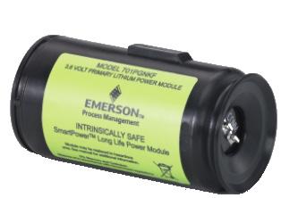
5 Figure 4. Green Power Module Installation Green power module (701PGN) 1. Install the HART device according to standard installation practices and the manufacturer s instructions, being sure to use an approved thread sealant on all connections. 2. Unscrew the power module cover from the wireless device. 3. Connect the Green power module to the wireless device. The Green power module has a keyed connection to prevent improper connection. If the Green power module is placed into the housing the wrong way, it will not fit entirely into the housing. Note Wireless devices should be powered up in order of proximity from the Smart Wireless Gateway, beginning with the closest device to the Gateway. This will result in a simpler and faster network installation. 4. Close the housing cover and tighten. Ensure the power module cover is fully tightened to prevent moisture ingress. The lip of the polymer power module cover should be in contact with the surface of the polymer enclosure to ensure a proper seal. Do not over tighten. Step 2: Verify operation Operation can be verified in four locations: by using the Field Communicator, at the Gateway via the Smart Wireless Gateway s integrated web server, via AMS Wireless Configurator, or with the wireless device s LCD display. Field Communicator If you are able to communicate to the wireless device via a Field Communicator, the power module is powering the device and working correctly. Figure 5 shows how to connect a Field Communicator to a wireless device with either the black or green power module. 5
6 1 2 P/N COMM Figure 5. Field Communicator Connections Figure Field Communicator Smart Wireless Gateway If the wireless device was configured with the Network ID and Join Key, and sufficient time has passed for network polling, the transmitter will be connected to the network. To verify device operation and connection to the network with the Smart Wireless Gateway s integrated web server, open the Smart Wireless Gateway s integral web interface and navigate to the Explorer page. If the wireless device has joined the network, the power module is functioning properly. Note It may take several minutes for the device to join the network. 6

7 AMS Wireless Configurator When the device has joined the network, it will appear in the Wireless Configurator as illustrated below. Figure 7. AMS Wireless Configurator Wireless device LCD display If the wireless device that you are connecting the power module to has an LCD display, it can be used to verify operation. When the power module is first connected to the wireless device, the LCD display will turn on for approximately 40 seconds. If the LCD display turns on after the power module is installed, the power module is functioning properly. Troubleshooting If the wireless device does not turn on after the power module is installed, the power module may be depleted. Change out the power module and see if the wireless device turns on. If not, refer to the troubleshooting section of the wireless device's manual. 7
8 Disposal/recycling of depleted power modules 1. Dispose in accordance with applicable laws and regulations in your country and state. 2. Disposal should only be performed by authorized professionals in accordance with applicable requirements for hazardous waste transportation and disposal. 3. Incineration should only be performed by trained professionals in authorized facilities. Shipping regulations Primary lithium batteries are regulated in transportation by the U.S. Department of Transportation, and are also covered by IATA (International Air Transport Association), ICAO (International Civil Aviation Organization), and ARD (European Ground Transportation of Dangerous Goods). It is the responsibility of the shipper to ensure compliance with these or any other local requirements. Please consult current regulations and requirements before shipping. Handling considerations Each black power module contains two C size primary lithium batteries. Each green power module contains one D size primary lithium battery. Under normal conditions, the battery materials are self-contained and are not reactive as long as the batteries and the battery pack integrity are maintained. Care should be taken to prevent thermal, electrical, or mechanical damage. Contacts should be protected to prevent premature discharge. Use caution when handling the power module. It may be damaged if dropped onto a hard surface. Battery hazards remain when cells are discharged. Environmental considerations As with any battery, local environmental rules and regulations should be consulted for proper management of spent batteries. If no specific requirements exist, recycling through a qualified recycler is encouraged. Consult the materials safety data sheet for battery specific information. 8
9 Product Certifications European Directive Information A copy of the EC Declaration of Conformity can be found at the end of the Quick Start Guide. The most recent revision of the EC Declaration of Conformity can be found at Ordinary Location Certification from FM Approvals As standard, the transmitter has been examined and tested to determine that the design meets the basic electrical, mechanical, and fire protection requirements by FM Approvals, a nationally recognized test laboratory (NRTL) as accredited by the Federal Occupational Safety and Health Administration (OSHA). Installing in North America USA KF The US National Electrical Code (NEC) and the Canadian Electrical Code (CEC) permit the use of Division marked equipment in Zones and Zone marked equipment in Divisions. The markings must be suitable for the area classification, gas, and temperature class. This information is clearly defined in the respective codes. FM Intrinsically Safe (IS) Certificate: Standards: FM Class , FM Class , FM Class Markings: IS CL I, DIV 1, GP A, B, C, D; CL II, DIV 1, GP E, F, G; Class III; Class 1, Zone 0 AEx ia IIC T4; (-40 C Ta +70 C) (See Table 1 or Table 2 for parameters) Canada KF Special Condition for Safe Use (X): Replacement of power module, see instructions for final product CSA Intrinsically Safe Certificate: Standards: CAN/CSA C22.2 No. 0-M91, CSA Std C22.2 No Markings: Intrinsically Safe Class I, Division 1, Groups A, B, C, and D T3C (Ta +70 C) Warning - refer to QIG for Safe I.S. Use (See Table 1 or Table 2 for parameters) Special Condition for Safe Use (X): The power modules are certified as components for use in intrinsically safe products where the suitability/combination of use in the final assembly shall be subjected to CSA acceptance. The final assembly must incorporate all protection features necessary for batteries in accordance with applicable standards of the final intrinsically safe application. 9
10 Europe KF ATEX Intrinsic Safety Certificate: Baseefa11ATEX0042X Standards: EN : 2012, EN : 2012 Markings: II 1 G Ex ia IIC T4 Ga, T4(-55 C Ta +70 C) II 1 G Ex ia IIC T5 Ga, T5(-55 C Ta +40 C) (See Table 1 or Table 2 for parameters) Special Condition for Safe Use (X): 1. The plastic enclosure of the Model 701P SmartPower Power Modules may constitute a potential electrostatic ignition risk and caution should be used when being handled. Note This condition of use does not apply after a power module is installed within a wireless transmitter enclosure. International KF IECEx Intrinsic Safety Certificate: IECEx BAS X Standards: IEC : 2011, IEC : 2011 Markings: Ex ia IIC T4/T5 Ga, T4(-55 C Ta +70 C), T5(-55 C Ta +40 C) Special Condition for Safe Use (X): 1. The plastic enclosure of the Model 701P SmartPower Power Modules may constitute a potential electrostatic ignition risk and caution should be used when being handled. Note This condition of use does not apply after a power module is installed within a wireless transmitter enclosure. EAC - Belarus, Kazakhstan, Russia KF Technical Regulation Customs Union (EAC) Intrinsic Safety Certificate: RU C-US.Gb05.B Markings: 0Ex ia IIC T4/T5 Ga X T4 (-55 C Ta +70 C) T5 (-55 C Ta +40 C) 10
11 Table BK Safety parameters U o I o P o C o L o 7.8 V 2.16 A 0.83 W 3.0 μf 7.6 μh Table PGN Safety parameters U o I o P o C o L o 3.9 V 2.78 A 2.71 W 100 μf 4.6 μh 11
12 Figure P EC Declaration of Conformity EC Declaration of Conformity No: RMD 1085 Rev. A We, Rosemount Inc Market Boulevard Chanhassen, MN USA declare under our sole responsibility that the product, manufactured by, 701P SmartPower Power Module Rosemount Inc Technology Drive and 8200 Market Boulevard Eden Prairie, MN Chanhassen, MN USA USA to which this declaration relates, is in conformity with the provisions of the European Community Directives, including the latest amendments, as shown in the attached schedule. Assumption of conformity is based on the application of the harmonized standards and, when applicable or required, a European Community notified body certification, as shown in the attached schedule. (signature) Vice President, Global Quality & Customer Care (function) Timothy J. Layer 29 August, 2011 (name) (date of issue) 12
 All Models Harmonized Standards: EN 61326-1:2006 ATEX Directive (94/9/EC) 701P SmartPower")


13 Schedule EC Declaration of Conformity RMD 1085 Rev. A EMC Directive (2004/108/EC) All Models Harmonized Standards: EN :2006 ATEX Directive (94/9/EC) 701P SmartPower Power Module Baseefa11ATEX0042X - Intrinsic Safety Certificate Equipment Group II Category 1G Ex ia T4 Ga -60 C Ta +70 C T5 Ga -60 C Ta +40 C Harmonized Standards Used: EN :2009; EN :2007 ATEX Notified Bodies for EC Type Examination Certificate Baseefa. [Notified Body Number: 1180] Rockhead Business Park Staden Lane Buxton, Derbyshire SK17 9RZ United Kingdom ATEX Notified Body for Quality Assurance Baseefa. [Notified Body Number: 1180] Rockhead Business Park Staden Lane Buxton, Derbyshire SK17 9RZ United Kingdom File ID: Page 2 of 2 701P_RMD1085_RevA.docx 13
14 , Rev CA Rosemount World Headquarters Emerson Process Management 6021 Innovation Blvd Shakopee, MN 55379, USA or North America Regional Office Emerson Process Management 8200 Market Blvd. Chanhassen, MN 55317, USA or Latin America Regional Office Emerson Process Management 1300 Concord Terrace, Suite 400 Sunrise, Florida, 33323, USA Europe Regional Office Emerson Process Management Europe GmbH Neuhofstrasse 19a P.O. Box 1046 CH 6340 Baar Switzerland +41 (0) (0) Asia Pacific Regional Office Emerson Process Management Asia Pacific Pte Ltd 1 Pandan Crescent Singapore Enquiries@AP.EmersonProcess.com Middle East and Africa Regional Office Emerson Process Management Emerson FZE P.O. Box 17033, Jebel Ali Free Zone - South 2 Dubai, United Arab Emirates RFQ.RMTMEA@Emerson.com Standard Terms and Conditions of Sale can be found at: The Emerson logo is a trade mark and service mark of Emerson Electric Co. AMS is a registered trademark of Emerson Process Management. SmartPower is a trademark of Rosemount, Inc. Rosemount and the Rosemount logotype are registered trademarks of Rosemount Inc. HART is a registered trademark of the FieldComm Group Rosemount Inc. All rights reserved.
SmartPower Solutions [ SmartPower Solutions. Quick Installation Guide , Rev AC January 2012
 Start Step 1: Physical Installation Step 2: Verify Operation Disposal/Recycling of Depleted Power Modules Product Certifications EC Declaration of Conformity End 00825-0100-4701[ 2012 Rosemount Inc. All
Rosemount 702 Wireless Discrete Transmitter
 August 2009 Rosemount 702 Rosemount 702 Wireless Discrete Transmitter Start Step 1: Physical Installation Step 2: Verify Operation Step 3: Reference Information Product Certifications EC Declaration of
Rosemount 0085 Pipe Clamp Sensor Assembly. Quick Start Guide , Rev CA June 2016
 Rosemount 0085 Pipe Clamp Sensor Assembly 00825-0100-4952, Rev CA NOTICE This guide provides basic guidelines for Rosemount 0085 Pipe Clamp Sensor. It does not provide instructions for configuration, diagnostics,
SmartPower Solutions. SmartPower Solutions. Product Data Sheet , Rev AC January Contents
 Product Data Sheet Intrinsically Safe design enables ability to perform routine maintenance in hazardous areas Predictable life specified under installed conditions Robust design for use in harsh environments
Rosemount 214C Sensor. Quick Start Guide , Rev AF August 2017
 Rosemount 214C Sensor 00825-0400-2654, Rev AF NOTICE This guide provides basic guidelines for Rosemount 214C Sensor models. If the sensor was ordered assembled to a temperature thermowell or transmitter,
Emerson Wireless SmartPower Solutions
 Product Data Sheet 00813-0100-4701 Rev CA Emerson Wireless SmartPower Solutions Intrinsically Safe design enables routine maintenance in hazardous areas Predictable life specified under installed conditions
Rosemount 0085 Pipe Clamp Sensor Assembly. Quick Start Guide , Rev DC August 2017
 Rosemount 0085 Pipe Clamp Sensor Assembly Quick Start Guide 00825-0100-4952, Rev DC Quick Start Guide NOTICE This guide provides basic guidelines for Rosemount 0085 Pipe Clamp Sensor. It does not provide
Rosemount 705 Wireless Totalizing Transmitter
 Quick Start Guide 00825-0200-4705, Rev CB Rosemount 705 Wireless Totalizing Transmitter An installation-ready solution that provides simple connection to a turbine meter. Measures average flow and totalized
Quick Start Guide , Rev EA December Rosemount 0065/0185 Sensor Assembly
 Quick Start Guide 00825-0200-2654, Rev EA Rosemount 0065/0185 Sensor Assembly Quick Start Guide NOTICE This guide provides basic guidelines for Rosemount 0065 and 0185 Sensor models. It does not provide
Quick Start Guide , Rev DA December Rosemount Volume 1 Sensor Assembly
 Quick Start Guide 00825-0300-2654, Rev DA Rosemount Volume 1 Sensor Assembly Quick Start Guide NOTICE This guide provides basic guidelines for Rosemount 0068, 0078, and 0183 Sensor models. It does not
Rosemount 3490 Series 4 20 ma + HART Compatible Controller
 00825-0200-4841, Rev AB Rosemount 3490 Series 4 20 ma + HART Compatible Controller Failure to follow safe installation guidelines could result in death or serious injury The Rosemount 3490 Series Control
Rosemount 148 Temperature Transmitter. Quick Start Guide , Rev GA September 2016
 Rosemount 148 Temperature Transmitter 00825-0100-4148, Rev GA NOTICE This guide provides basic guidelines for the Rosemount 148. It does not provide instructions for detailed configuration, diagnostics,
Rosemount 4600 Oil & Gas Panel Pressure Transmitter. Quick Start Guide , Rev GA September 2017
 Rosemount 4600 Oil & Gas Panel Pressure Transmitter 00825-0100-4022, Rev GA NOTICE NOTICE This guide provides basic guidelines for the Rosemount 4600 Oil & Gas Panel Pressure Transmitter. It does not provide
Quick Start Guide , Rev CB May Rosemount 3144P Temperature Transmitters with FOUNDATION fieldbus Protocol
 Quick Start Guide 00825-0100-4834, Rev CB Rosemount 3144P Temperature Transmitters with FOUNDATION fieldbus Protocol Quick Start Guide NOTICE NOTICE This guide provides basic guidelines for the Rosemount
Rosemount 752 FOUNDATION Fieldbus Remote Indicator
 Rosemount 752 FOUNDATION Fieldbus Remote Indicator Product Data Sheet 00813-0100-4377, Rev FA Two-wire segment powered device Displays up to eight values Link Master Capability Optional PID, Characterizer,
Rosemount 752 Remote Indicator
 Quick Start Guide 00825-0100-4377, Rev EA Rosemount 752 Remote Indicator with FOUNDATION Fieldbus Protocol Quick Start Guide This guide provides basic guidelines for Rosemount 752 Remote Indicator. It
Annubar Flowmeter Series
 Reference Manual Appendix B Approvals Annubar Flowmeter Series Hazardous Locations Installations.................. page B-1 Rosemount 3051SFA Product Certifications.......... page B-1 Rosemount 3095MFA
Rosemount 2160 Wireless Vibrating Fork Level Switch
 January 2012 Rosemount 2160 Rosemount 2160 Wireless Vibrating Fork Level Switch Start Considerations and Recommendations Step 1: Physical Installation Step 2: Verify Operation Step 3: Reference Information
Rosemount 3051HT Hygienic Pressure Transmitter
 00825-0100-4091, Rev CA Rosemount 3051HT Hygienic Pressure Transmitter with 4 20 ma HART Revision 5 and 7 Protocol Note Before installing the transmitter, confirm the correct device driver is loaded on
Rosemount 2090F Hygienic Pressure Transmitter
 Rosemount 2090F Hygienic Pressure Transmitter Product Data Sheet November 2016 00813-0100-4698, Rev FC Conforms to 3-A Sanitary Standards Features CIP/SIP service for process temperatures up to 284 F (140
Rosemount Pipe Clamp Sensor. Reference Manual , Rev BA February 2014
 Rosemount Pipe Clamp Sensor Reference Manual Reference Manual Title Page The Rosemount 0085 Pipe Clamp Sensor NOTICE Read this manual before working with the product. For personal and system safety, and
Rosemount 4600 Oil & Gas Panel Pressure Transmitter
 Product Data Sheet October 2017 00813-0100-4022, Rev LA Rosemount 4600 Oil & Gas Panel Pressure Transmitter A compact, lightweight, all-welded stainless steel design Up to 40:1 rangeability for increased
Rosemount 2051G Pressure Transmitter
 Quick Start Guide 00825-0700-4101, Rev AB Rosemount 2051G Pressure Transmitter with 4 20 ma HART Protocol (Revision 5 and 7) Quick Start Guide NOTICE This guide provides basic guidelines for Rosemount
Rosemount 248 Temperature Transmitter. Quick Start Guide , Rev. EA April 2013
 Rosemount 248 Temperature Transmitter 00825-0100-4825, Rev. EA NOTICE This installation guide provides basic guidelines for the Rosemount 248 Wireless. It does not provide instructions for detailed configuration,
Rosemount 4500 Hygienic Pressure Transmitter. Start
 Quick Installation Guide June 2007 Rosemount 4500 Rosemount 4500 Hygienic Pressure Transmitter ProductDiscontinued Start Step 1: Mount the Transmitter Step 2: Set the Switches Step 3: Connect Wiring and
Rosemount Wireless Pressure Gauge
 00825-0100-4045, Rev AE Rosemount Wireless Pressure Gauge with WirelessHART Protocol NOTICE This guide provides basic guidelines for Rosemount Wireless Pressure Gauges. It does not provide instructions
Rosemount 3490 Series
 Product Data Sheet July 2014 00813-0100-4841, Rev DA Rosemount 3490 Series 4 20 ma + HART Compatible Controller Field mounted controller with integral multi-function LCD and keypad Tough weatherproof wall
STEAM TRAP HEALTH MONITORING SERVICE EXECUTIVE SUMMARY
 STEAM TRAP HEALTH MONITORING SERVICE EXECUTIVE SUMMARY OVERVIEW Emerson s Steam Trap Health Monitoring Service at customer facility began November 15, 2015. A total of 184 steam traps are being monitored
Rosemount 4500 Hygienic Pressure Transmitter Demonstrated best-in-class performance during SIP/CIP for process temperatures up to 400 F (204 C)
") Product Data Sheet December 2012 00813-0100-4027, Rev BB Rosemount 4500 Hygienic Pressure Transmitter ProductDiscontinued R 37-01 Hygienic design conforms to 3-A and EHEDG standards Demonstrated best-in-class
Product Data Sheet December 2012 00813-0100-4027, Rev BB Rosemount 4500 Hygienic Pressure Transmitter ProductDiscontinued R 37-01 Hygienic design conforms to 3-A and EHEDG standards Demonstrated best-in-class
Rosemount 2090F Hygienic Pressure Transmitter
 Rosemount 2090F Hygienic Pressure Transmitter Product Data Sheet December 2017 00813-0100-4698, Rev GA Conforms to 3-A Sanitary Standards Features CIP/SIP service for process temperatures up to 284 F (140
Rosemount 3100 Series Ultrasonic Level Transmitters
 Product Data Sheet Ultrasonic Level Transmitters Non-contacting measurement with no moving parts Integral LCD and push-buttons as standard for on-site programming Continuous measurement of level or distance-to-surface.
Net Safety ST3 XChem Toxic Gas Sensor
 Product Data Sheet 00813-0100-4303, Rev AA Net Safety ST3 XChem Toxic Gas Sensor Millennium II Series Sensors Net Safety ST3 Overview The Net Safety ST3 XChem series of electrochemical toxic gas sensors
Rosemount 2088, 2090F, and 2090P Pressure Transmitter
 Quick Start Guide 00825-0100-4108, Rev BA Rosemount 2088, 2090F, and 2090P Pressure Transmitter with 4-20 ma HART and 1-5 Vdc Low Power HART Protocol (Revision 5 and 7) Quick Start Guide NOTICE This guide
Rosemount 752 Fieldbus Remote Indicator
 Product Data Sheet Rosemount 752 Rosemount 752 Fieldbus Remote Indicator ROSEMOUNT 752 DELIVERS: Two-wire segment powered device Displays up to 8 values Link Master Capability Optional PID, Characterizer,
Rosemount 3144P Temperature Transmitter
 00825-0100-4021, Rev MA Rosemount 3144P Temperature Transmitter with HART Protocol and Rosemount X-well Technology NOTICE This guide provides basic guidelines for the Rosemount 3144P Transmitter. It does
Rosemount 4500 Hygienic Pressure Transmitter
 Product Data Sheet Rosemount 4500 Rosemount 4500 Hygienic Pressure Transmitter Hygienic design conforms to 3-A and EHEDG standards Demonstrated best-in-class performance during SIP/CIP for process temperatures
Rosemount High Density Temperature Measurement. Simplify Your Project
 Rosemount High Density Temperature Measurement Simplify Your Project 848 Balancing Project Risk is a Daunting Challenge Emerson s approach to temperature measurement can help lower the risk of budget overruns
Quick Start Guide , Rev. BB February Rosemount 1495 Orifice Plate Rosemount 1496 Orifice Flange Union
 00825-0100-4792, Rev. BB Rosemount 1495 Orifice Plate Rosemount 1496 Orifice Flange Union NOTICE This installation guide provides basic guidelines for Rosemount 1495 Conditioning Orifice Plate. It does
Rosemount 3100 Series Ultrasonic Level Transmitters
 Product Data Sheet Ultrasonic Level Transmitters Non-contacting measurement with no moving parts Integral LCD and push-buttons as standard for on-site programming Continuous measurement of level or distance-to-surface.
Rosemount 2090P Pulp and Paper Pressure Transmitter
 Product Data Sheet Rosemount 2090P Pulp and Paper Pressure Transmitter Rosemount 2090P 1-inch flush mount compatible with a PMC process connection, or 1 1 /2-inch threaded mounting connection Absolute
Rosemount 2088, 2090P, and 2090F Pressure Transmitters
 Quick Start Guide 00825-0100-4690, Rev FD Rosemount 2088, 2090P, and 2090F Pressure Transmitters with 4 20 ma HART and 1 5 Vdc HART Low Power Protocol Quick Start Guide NOTICE This installation guide provides
Emerson Plantweb Insight
 Emerson Plantweb Insight Configuration and Information Overview............................................................................ page 1 Global settings.......................................................................
Rosemount 644H and 644R Smart Temperature Transmitters
 Quick Installation Guide March 2011 Rosemount 644 Rosemount 644H and 644R Smart Temperature Transmitters Start Step 1: Configure (Bench Calibration) Step 2: Verify Configuration Step 3: Set the Switches
Rosemount 3144P Temperature Transmitters with FOUNDATION Fieldbus Protocol. Quick Start Guide , Rev DA June 2016
 Rosemount 3144P Temperature Transmitters with FOUNDATION Fieldbus Protocol 00825-0100-4834, Rev DA NOTICE This guide provides basic guidelines for Rosemount 3144P. It does not provide instructions for
Model 144H. Product Data Sheet , Rev DB February Content
 Rosemount 144 PC-Programmable Temperature Transmitter Provides an installation-ready solution for temperature monitoring applications using Complete Point Solutions (CPS) Increases measurement accuracy
Rosemount 644 Temperature Transmitter
 Quick Start Guide 00825-0200-4728, Rev GB Rosemount 644 Temperature Transmitter with 4 20 ma HART Protocol (Revision 5 and 7) Note Before installing the transmitter, confirm the correct device driver is
Rosemount 848T FOUNDATION Fieldbus High Density Temperature Transmitter
 Quick Start Guide 00825-0100-4697, Rev SF Rosemount 848T FOUNDATION Fieldbus High Density Temperature Transmitter Device Revision 8 - Requires New DD/CFF Revision Quick Start Guide NOTICE This guide provides
Quick Start Guide , Rev HA January Rosemount 248 Temperature Transmitter
 00825-0100-4825, Rev HA Rosemount 248 Temperature Transmitter NOTICE This guide provides basic guidelines for the Rosemount 248. It does not provide instructions for detailed configuration, diagnostics,
Certification Supplement Manual
 PROCESS ANALYSERS SERVOTOUGH FluegasExact (2700) Gas Analyser Certification Supplement Manual Part Number: 02700008D Revision: 2 Language: UK English Blank CONTENTS 1 INTRODUCTION 2 EC DECLARATION OF CONFORMITY
Rosemount 3490 Series 4 20 ma + HART Compatible Controller
 00825-0100-4841, Rev BA Rosemount 3490 Series 4 20 ma + HART Compatible Controller Quick Start Guide for Installation Failure to follow safe installation guidelines could result in death or serious injury
Rosemount 2100 Series
 Rosemount 2100 Series Vibrating Fork Liquid Level Switches Level switches for demanding applications Reliable performance... Rosemount 2100 series vibrating fork level switches are suitable for virtually
Rosemount 644H Temperature Transmitters
 Quick Start Guide 00825-0300-4728, Rev BA Rosemount 644H Temperature Transmitters with PROFIBUS PA Quick Start Guide NOTICE This guide provides basic guidelines for the Rosemount 644. It does not provide
Instruction Manual. CAT 100 & CAT 200 Continuous Analyzer Transmitter Addendum for Hazardous Area Applications. 3 rd Edition 05/2007
 CAT 100 & CAT 200 Continuous Analyzer Transmitter Addendum for Hazardous Area Applications 3 rd Edition www.emersonprocess.com CAT 100 & CAT 200 Addendum for Hazardous Area Applications ESSENTIAL INSTRUCTIONS
Rosemount 644H Temperature Transmitters
 Quick Start Guide 00825-0100-4829, Rev DA Rosemount 644H Temperature Transmitters with FOUNDATION Fieldbus Quick Start Guide NOTICE This guide provides basic guidelines for the Rosemount 644. It does not
Rosemount 3144P Temperature Transmitter
 Quick Start Guide 00825-0100-4021, Rev NA Rosemount 3144P Temperature Transmitter with HART Protocol and Rosemount X-well Technology Quick Start Guide NOTICE This guide provides basic guidelines for the
Certification Supplement Manual
 SERVOTOUGH FluegasExact (2700) Gas Analyser Certification Supplement Manual Part Number: 02700008D Revision: 5 Language: UK English Blank CONTENTS 1 INTRODUCTION 2 EU DECLARATION OF CONFORMITY 3 EUROPEAN
Rosemount 2088, 2090F, and 2090P Pressure Transmitter
 Quick Start Guide 00825-0100-4108, Rev CA Rosemount 2088, 2090F, and 2090P Pressure Transmitter with 4 20 ma HART and 1 5 Vdc Low Power HART Protocol (Revision 5 and 7) Quick Start Guide NOTICE This guide
Model 144H. Product Data Sheet , Rev DB February Content
 Rosemount 144 PC-Programmable Temperature Transmitter Provides an installation-ready solution for temperature monitoring applications using Complete Point Solutions (CPS) Increases measurement accuracy
Rosemount 4088B MultiVariable Transmitter with Bristol Standard Asynchronous/Synchronous Protocol (BSAP)/MVS Protocol
/MVS Protocol") Quick Start Guide 00825-0200-4088, Rev CA Rosemount 4088B MultiVariable Transmitter with Bristol Standard Asynchronous/Synchronous Protocol (BSAP)/MVS Protocol Quick Start Guide NOTICE This installation
Quick Start Guide 00825-0200-4088, Rev CA Rosemount 4088B MultiVariable Transmitter with Bristol Standard Asynchronous/Synchronous Protocol (BSAP)/MVS Protocol Quick Start Guide NOTICE This installation
Quick Start Guide LIQ-QSG-Hx438, Rev A June Rosemount Hx438. Amperometric Steam Sterilizable Dissolved Oxygen Sensors
 Quick Start Guide LIQ-QSG-Hx438, Rev A June 2017 Rosemount Hx438 Amperometric Steam Sterilizable Dissolved Oxygen Sensors Safety Information WARNING! Do not exceed temperature and pressure limitations
IECEx Certificate of Conform ity
 IECEx Certificate of Conform ity INTERNATIONAL ELECTROTECHNICAL COMMISSION IEC Certification Scheme for Explosive Atmospheres for rules and details of the IECEx Scheme visit www.iecex.com Certificate No.:
Rosemount Functional Safety Manual. Manual Supplement , Rev AF March 2015
 Rosemount 2120 Functional Safety Manual Manual Supplement Manual Supplement Contents Contents 1Section 1: Introduction 1.1 Scope and purpose of the safety manual.................................. 1 1.2
Rosemount 644H Temperature Transmitters
 Quick Start Guide 00825-0300-4728, Rev CA Rosemount 644H Temperature Transmitters with PROFIBUS PA Quick Start Guide NOTICE This guide provides basic guidelines for the Rosemount 644. It does not provide
Rosemount 3051S MultiVariable Transmitter Rosemount 3051SF Series MultiVariable Flowmeter
 Quick Start Guide 00825-0100-4853, Rev AD Rosemount 3051S MultiVariable Transmitter Rosemount 3051SF Series MultiVariable Flowmeter with FOUNDATION Fieldbus Protocol Quick Start Guide NOTICE This guide
Rosemount 1595 Conditioning Orifice Plate
 Quick Installation Guide December 2007 Rosemount 1595 Rosemount 1595 Conditioning Orifice Plate Start Step 1: Primary Element Location Step 2: Primary Element Orientation Step 3: Primary Element Installation
Rosemount 3051S Electronic Remote Sensors
 Rosemount 3051S Electronic Remote Sensors Reach New Heights with Your Instrumentation A New Answer to an Old Problem Everyone has an installation that consumes time and resources, whether it s a distillation
Rosemount 2090F Hygienic Pressure Transmitter
 Hygienic Pressure Transmitter Conforms to 3-A Sanitary s Features CIP/SIP service for process temperatures up to 284 F (140 C) Absolute or gage pressure ranges from 0-1.5 to 0-300 psi Mounts with either
Rosemount 2051 Pressure Transmitter and Rosemount 2051CF Series Flowmeter
 Quick Start Guide 00825-0400-4101, Rev AD Rosemount 2051 Pressure Transmitter and Rosemount 2051CF Series Flowmeter with PROFIBUS PA Protocol Quick Start Guide NOTICE This installation guide provides basic
Rosemount 2051 Pressure Transmitter with 4-20 ma HART and 1-5 Vdc HART Low Power Protocol
 Quick Installation Guide August 2009 Rosemount 2051 Rosemount 2051 Pressure Transmitter with 4-20 ma HART and 1-5 Vdc HART Low Power Protocol Start Step 1: Mount the Transmitter Step 2: Consider Housing
Rosemount 2088, 2090P, and 2090F Pressure Transmitters
 April 2013 Rosemount 2088 and 2090 Rosemount 2088, 2090P, and 2090F Pressure Transmitters with 4-20 ma HART and 1-5 Vdc HART Low Power Protocol Start Step 1: Mount the Transmitter Step 2: Set the Jumpers
Rosemount 3051 Pressure Transmitter and Rosemount 3051CF Series Flowmeter
 Quick Start Guide 00825-0100-4797, Rev ED Rosemount 3051 Pressure Transmitter and Rosemount 3051CF Series Flowmeter with PROFIBUS PA Protocol Quick Start Guide NOTICE This installation guide provides basic
Quick Start Guide , Rev DA June Rosemount 644H (Device Revision 7 or Previous) and 644R Smart Temperature Transmitters
 and 644R Smart Temperature Transmitters") Quick Start Guide 00825-0100-4728, Rev DA Rosemount 644H (Device Revision 7 or Previous) and 644R Smart Temperature Transmitters Quick Start Guide NOTICE This guide provides basic guidelines for the Rosemount
Quick Start Guide 00825-0100-4728, Rev DA Rosemount 644H (Device Revision 7 or Previous) and 644R Smart Temperature Transmitters Quick Start Guide NOTICE This guide provides basic guidelines for the Rosemount
Rosemount 248 Temperature Transmitter
 Product Data Sheet March 2017 00813-0100-4825, Rev LA Rosemount 248 Temperature Transmitter Basic temperature transmitter offers a reliable solution for temperature monitoring points. Standard transmitter
805QS Pressure Switch-Transmitter
 805QS Pressure Switch-Transmitter These instructions provide information for installation, process connection, n, electrical connection, operation and maintenance of the 805QS pressure switch-transmitter.
Certificate of Compliance
 FF0002 Certificate of Compliance Certificate: 2792948 Issued to: Siemens Canada Limited 1954 Technology Drive Peterborough, ON K9J 7B1 Canada Attention: Mr. Lee Rogers The products listed below are eligible
Rosemount 2088 Absolute and Gage Pressure Transmitter
 Product Data Sheet Rosemount 2088 Rosemount 2088 Absolute and Gage Pressure Transmitter Performance of 0.075% with High Accuracy option Lightweight, compact design for cost effective installation Protocols
Rosemount 3051S MultiVariable Transmitter
 HART Reference Card HART Rosemount 3051SMV Rosemount 3051S MultiVariable Transmitter A check ( ) indicates the basic configuration parameters. At minimum, these parameters should be verified as part of
Rosemount 3051S MultiVariable Transmitter Rosemount 3051SF Series Flowmeter MultiVariable Transmitter
 Quick Start Guide 00825-0100-4803, Rev EA Rosemount 3051S MultiVariable Transmitter Rosemount 3051SF Series Flowmeter MultiVariable Transmitter Quick Start Guide NOTICE This guide provides basic guidelines
IECEx Certificate. INTERNATIONAL ELECTROTECHNICAL COMMISSION IEC Certification Scheme for Explosive Atmospheres
 INTERNATIONAL ELECTROTECHNICAL COMMISSION IEC Certification Scheme for Explosive Atmospheres for rules and details of the IECEx Scheme visit www.iecex.com Certificate No.: Certificate history: Status:
Rosemount 3051 Pressure Transmitter
 Quick Start Guide 00825-0100-4001, rev. JA Rosemount 3051 Pressure Transmitter with 4-20 ma HART and 1-5 Vdc Low Power Protocol Rosemount 3051CF Series Flowmeter Transmitter with 4-20 ma HART and 1-5 Vdc
Rosemount 8800D Series Vortex Flowmeter
 Quick Installation Guide Rosemount 8800D Rosemount 8800D Series Vortex Flowmeter Start Step 1: Mount the Flowmeter Step 2: Consider Housing Rotation Step 3: Set Jumpers and Switches Step 4: Connect Wiring
Rosemount 3051S MultiVariable Extension Supplement
 Product Data Sheet April 2015 00813-0400-4801, Rev AA Rosemount 3051S MultiVariable Extension Supplement With the Rosemount 3051S MultiVariable Extensions, you can gain valuable process insight with two
Quick Start Guide LIQ-QSG-Hx338, Rev M July Rosemount Hx338. Steam Sterilizable and Autoclavable ph Sensor
 Quick Start Guide LIQ-QSG-Hx338, Rev M July 2017 Rosemount Hx338 Steam Sterilizable and Autoclavable ph Sensor Safety Information WARNING! Do not exceed temperature and pressure limitations of 266 F (130
Rosemount 248 Temperature Transmitter
 Product Data Sheet November 2013 00813-0100-4825, Rev KA Rosemount 248 Temperature Transmitter Basic temperature transmitter offers a reliable solution for temperature monitoring points transmitter design
Rosemount 2090F Sanitary Pressure Transmitter with HART Protocol
 Sanitary Pressure Transmitter with HART Protocol A TRADITION OF EXCELLENCE IN PERFORMANCE Conforms to 3-A Sanitary Standards Features CIP/SIP service with an upper temperature limit of 284 F (140 C) USDA
Rosemount 2140 and 2140:SIS Level Detectors
 Product Data Sheet 00813-0100-4140, Rev BB Rosemount 2140 and 2140:SIS Level Detectors Vibrating ork Integrates into existing wired HART loops of automated systems without extra wiring costs Switch between
IECEx Certificate of Conformity
 INTERNATIONAL ELECTROTECHNICAL COMMISSION IEC Certification Scheme for Explosive Atmospheres for rules and details of the IECEx Scheme visit www.iecex.com Certificate No. : Status: Date of Issue: Applicant:
Rosemount 3051S Series Pressure Transmitter and Rosemount 3051SF Series Flowmeter
 Quick Start Guide 00825-0100-4801, Rev MC Rosemount 3051S Series Pressure Transmitter and Rosemount 3051SF Series Flowmeter with HART Protocol Quick Start Guide NOTICE This guide provides basic guidelines
Duct Mount. Installation Instructions
 Duct Mount Installation Instructions 00809-0600-4975 Legal Notice The Flame Detector described in this document is the property of Rosemount. No part of the hardware, software, or documentation may be
Rosemount 248 Temperature Transmitter
 Product Data Sheet January 2018 00813-0100-4825, Rev LB Rosemount 248 Temperature Transmitter Basic temperature transmitter offers a reliable solution for temperature monitoring points. Standard transmitter
Guide to Hazardous Location Approvals:
 Selection Guide Guide to Hazardous Location Approvals: MICRO SWITCH Hazardous Area Limit Switches Introduction There are many considerations when selecting a switch to be used in hazardous areas. In addition
Dräger Polytron 5100 EC Detection of toxic gases and vapors
 Dräger Polytron 5100 EC Detection of toxic gases and vapors The Dräger Polytron 5100 EC is a cost-effective explosion proof transmitter for the detection of toxic gases or oxygen It uses a high performance
DB5 Intrinsically Safe Sounder Type DB-5
 Operating Instructions RTK Instruments Limited DB5 Intrinsically Safe Sounder Type DB-5 Description The DB5 Sounder is a strong, lightweight warning sounder, CENELEC certified to Ex II 1G EExia IIC T4
Rosemount 2088 Absolute and Gage Pressure Transmitter
 Product Data Sheet February 2015 00813-0100-4690, Rev PB Rosemount 2088 Absolute and Gage Pressure Transmitter Performance of 0.065% with High Accuracy option Lightweight, compact design for cost-effective
Rosemount 2130 Level Switch
 Rosemount 2130 Level Switch Vibrating Fork Product Data Sheet March 2017 00813-0100-4130, Rev EE Designed for operation in process temperatures of 94 to 500 F ( 70 to 260 C) Electronic self-checking and
Rosemount 3051P In-Line Pressure Transmitter. Product Data Sheet August , Rev BA
 Rosemount 3051P In-Line Pressure Transmitter Product Data Sheet August 2018 00813-0100-4680, Rev BA August 2018 Settings the standard for pressure measurement Proven best-in-class performance and safety
Rosemount 3051S MultiVariable Transmitter Rosemount 3051SF Series Flowmeter MultiVariable Transmitter
 00825-0100-4803, Rev EE Rosemount 3051S MultiVariable Transmitter Rosemount 3051SF Series Flowmeter MultiVariable Transmitter NOTICE This guide provides basic guidelines for the Rosemount 3051S MultiVariable
Advanced Diagnostics for HART Protocol Rosemount 3051S Scalable Pressure, Flow, and Level Solutions
 Advanced Diagnostics for HART Protocol Rosemount 3051S Scalable Pressure, Flow, and Level Solutions Predictive Intelligence for Your Success Achieve Superior Plant Performance More than ever, running a
Rosemount 3051 Pressure Transmitter Includes Transmitter Option TR ProductDiscontinued. Start
 Quick Installation Guide June 2009 Rosemount 3051 Rosemount 3051 Pressure Transmitter Includes Transmitter Option TR ProductDiscontinued Start Step 1: Mount the Transmitter Step 2: Consider Housing Rotation
RTK Instruments Limited St James Business Park, Knaresborough, North Yorkshire, England. HG5 8PJ
 Operating Instructions RTK Instruments Limited PEX7250 Explosion Proof Annunciator Introduction This manual provides the information necessary to install, connect, test and maintain the PEX7250 Explosion