31.05/ Unit-1
|
|
|
- Frank Garrett
- 5 years ago
- Views:
Transcription

1 Semi-Annual Inspection FS Report 31.05/ Unit-1 Customer Representative: GE Field Service Representative: All technical recommendations and information contained in this report are based on GE manuals that have been developed and approved for use with GE engines and parts that have been operated and maintained in accordance with GE technical documentation and recommendations. GE has no technical knowledge of, nor obligation for, non GE-approved parts and repairs. Accordingly, this report is not intended to apply to non GE-approved parts and repairs, nor to any parts that may be directly or indirectly affected by non GE-approved parts and repairs.
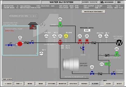
2 DETAILS AND DATA Purpose of visit: The purpose of this visit was to perform the Semi-Annual Inspections. Work performed: Control system part of Semi-Annual Inspections was performed. SAI Summary: ; - We arrived to the site at 19:30. But the unit was found in working condition. We had a small meeting with the customer about stop time of the unit and offline water wash period. Customer informed that, the unit will run until 21:00 due to commercial reason. We had to leave the site. Offline water wash has been started by customer ; - We arrived to the site at 01:00 - Offline water wash was completed by customer. (03:45) - LOTO was applied by customer. - All engine thermocouples and RTDs were simulated. T48 and T3 thermocouples were measured and found within limits except T48 A and F thermocouples. T48 A and F were replaced with new ones ; - All pressure transmitters were calibrated according to actual ambient pressure. Ambient pressure was measured as during the Semi-Annual Inspection. All pressure transmitter lines have been checked for leakage. - Turbine and Generator Lube Oil systems pressure transmitter and switch calibrations were checked. Switch setting values have been set according to site P & ID. - Over-speed alarm, trip points and external over-speed detection system have been checked. Alarm and trip signals were appeared on the HMI Screen. - Magnetic Chip Detectors were checked. Chip Detector A was found damaged. It was replaced with a new one. - 24VDC Control, FPP and 125 VDC Battery Charger Systems have been checked as visually. Electrolyte levels have been checked and found as normal level. Battery measurements were performed. 24 VDC battery system ground leakage was found on the (-) polarity. It needs to be investigated next available outage. - Gap voltage of generator vibration proxy sensors were measured and found as within tolerances. - Off-engine and on-engine cables have been inspected as visually. Observed no anomalies. All off-engine cable plugs have been checked for tightness. - Unit was started by customer due to commercial reasons. Unit was reached up 42 MW without any problem Gas Fuel system pressure transmitter calibrations were checked. Fuel gas metering valve calibration and shut-off valves have been checked. - Generator vent fan (A) air flow switch function checks were performed. Observed no anomalies. - Fire protection system faulty strobe was replaced with new one. All cables have been connected to their terminals. - FPP Combustible Gas Detectors have been calibrated. Two gas sensor sensitivities were measured out of limit. Only one gas sensor was provided by the customer and then it was replaced. Other gas sensor needs to be replaced with new one. Two combustible gas sensor needs to be ordered. Optical flame detectors have been checked for their functionality. Fire alarm was received and SOVs have been activated by FPP. Horns, strobes have been activated by FPP.CO2 release stations have been checked and received the alarm from the FPP and HMI. Report completed by 2
3 - Remote emergency stop buttons were not working. Necessary investigations were performed on the Emergency system. Cabling and their connections were checked. Incorrect connections were found. Faulty connections were corrected. All Emergency Stop buttons have been checked for their functionality. Observed no anomalies. - Hydraulic Start System solenoid valve (SOV 1619) was replaced with new one. Demand value has been adjusted back. Replaced solenoid valve is working without any problem. - Generator Jacking Oil HP pressure gauge calibrations were checked. Pressure gauges were found normal condition. Troubleshooting need to be performed on the jacking oil system. - For HMI counter corrections, new control software (Rev: H) which is provided by engineering, has been uploaded to the controller. However, Linknet N212 fault signal and connected signals were received. Old control software (Rev: F) has been uploaded to the controller again. However, Linknet N212 fault signal and connected signals were received again. Faulty Linknet was replaced with new one. New control software which is provided by engineering has not been uploaded to controller due to lack of enough time. The new software (Rev: H) needs to be installed at the first available outage. - Unit has been started by customer due to commercial reasons and reached up 42 MW without any problem. - Customer ADSL modem configurations were checked for OSM connection issue. ADSL modem was configured as bridge mode. However internet connection was not established between ADSL modem and Cisco modem. Latest customer ISP account details have been shared with engineering to check Cisco configuration. Report completed by 3
4 CONCLUSIONS & RECOMMENDATIONS Open Items: - New control software which is provided by engineering has not been uploaded to controller due to lack of enough time. The new software (Rev: H) needs to be installed at the first available outage. - (-) Polarity ground leakage was measured on the 24VDC system. It needs to be investigated as soon as possible. - Water Injection flow meter could not be replaced with new one due to lack of the spare part on site. It needs to be replaced when the new flow meter delivered to the site. - Customer ADSL modem configurations were checked for OSM connection issue. ADSL modem was configured as bridge mode. However internet connection was not established between ADSL modem and Cisco modem. Latest customer ISP account details have been shared with engineering to check Cisco configuration. - Generator Jacking Oil HP pressure gauge calibrations were checked. Pressure gauges were found normal condition. Troubleshooting need to be performed on the jacking oil system. Follow Up Action Items Engineering: Follow Up Action Items SM/CPM/PM: Outage Data: Engine Data: ESN xxx-xxx Engine Fired Hours - Package Hours Model Engine Fired Starts - Package Fired Starts 2513 Maintenance Data: WP, SB, SL, PB, PL Performed Revision/manual reference Date completed WP T48 Thermocouple Inspection WP Vibration Monitoring System Check WP Chip Detector Check Comments Parts Data: Description PN Removed SN Removed Qty Disposition PN Installed SN Installed STROBE 382A5419P Replaced 382A5419P T M86P02-2 Replaced 1962M86P02 - CHIP DETECTOR L43563P01-1 Replaced L43563P01 - LINKNET Replaced GAS SENSOR 334A3940P Replaced 334A3940P IGNITER 9392M95P04-1 Replaced 9392M95P04 - SOV A5502P Replaced 382A5502P Report completed by 4
5 UDETAILS AND DATA Work performed T48 Thermocouple Inspection T48 Thermocouple Measurement T48 Probe Insulation Resistance KP-KN Insulation Resistance KN-KP Average KP-KN(Ohm) T48A T48B T48C T48D T48E T48F T48G T48H As per the GEK Volume II WP ; KP to KN circuit resistance should be between 2,4 ohm and 4,1 ohm. Insulation resistance between plug and case should be > 5Mohm. Tag As Found As Left -70 ºF 0 ºF 900 ºF 1600 ºF 1900 ºF -70 ºF 0 ºF 900 ºF 1600ºF 1900 ºF T48 A T48 B T48 C T48 D T48 E T48 F T48 G T48 H Turbine Control system simulated and re- tuned according to T48 low and high set points. Observed no big differences. - Between KP/KN and case ohm was > 5Mohm for all the probes. Report completed by 5
6 UDETAILS AND DATA T3A TE-6838A T3 Calibration Data T3B TE-6838B Range -70 to 1200 ºF Range -70 to 1200 ºF KP-KN KN-KP KP-KN KN-KP Resistance Resistance Sim. Temperature As Found As Left Sim. Temperature As Found As Left As per the GEK , Volume I, between A and B and between C and D pins Resistance should be between 4,3 ohm and 6 Ohms. - Turbine Control system simulated and re- tuned according to T3 low and high set points. Observed small differences (max. 4-5 Fahrenheit) before the simulation. - On- engine and off-engine cable sockets were cleaned with Contact Cleaner before the re-installation. T2 Calibration Data T2A T2B Range -70 to 500 ºF Range -70 to 500 ºF Sim. Sim. Temp. As Found As Left Temp. As Found As Left Report completed by 6
7 DETAILS AND DATA Work performed: T25A T25 Calibration Data T25B Range -70 to 500 ºF Range -70 to 500 ºF Sim. Sim. Temp. As Found As Left Temp. As Found As Left Calibration Data of Pressure Transmitters Ambient pressure was measured as PSI. Tag Range PSIG As Found P As Left P25 Calibration Data Tag P25A Tag P25B Range Range PSIG As Found As Left PSIG As Found As Left Report completed by 7
8 DETAILS AND DATA Work performed: PS3 Calibration Data Tag PS3 A Tag PS3 B Range Range % PSIG As Found As Left % PSIG As Found As Left Vacuum Vacuum % % % % % % % % PTB Calibration Data Tag PTB A Tag PTB B Range Range PSIG As Found As Left PSIG As Found As Left P48 Calibration Data Tag P48 Range PSIG As Found As Left Report completed by 8
9 Redundant Over-speed System Check U Speed signals are simulated from the off-engine cable via signal generator. Speed signals have been monitored as shown below tables. The alarm and trip points have been appeared on the Alarm Page when we send; Redundant over speed system check was carried out according to the following set points. XN25A XN25B (Hz) (rpm) HMI (rpm) (Hz) (rpm) HMI (rpm) (alarm) 8090 (trip) (alarm) (trip) 1 Rpm = Hz Alarm Point: > Rpm = 8015 Hz Trip Point: > Rpm = Hz NSDA NSDB (Hz) (rpm) HMI (RPM) (Hz) (rpm) HMI (RPM) (trip) (trip) For NSD Speed Sensors; 1Rpm = 0.8 Hz Trip Point > 4050 Rpm = 3240 Hz Report completed by 9
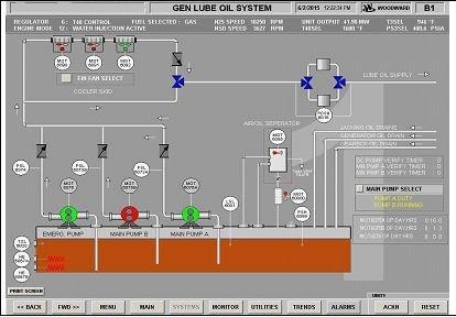
10 VIBRATION MONITORING SYSTEM - Vibration Monitoring System was checked according to WP Vibration signals were appeared on the HMI Screen. According to manual Check accelerometers by tapping it lightly with a small object (screwdriver handle). Accelerometer is good if control panel shows an indication of tapping, - During the taping test, indication was observed on HMI from the both accelerometers. GENERATOR GAP VOLTAGE ID NUMBER DESCRIPTION SET POINT UNIT AS FOUND AS LEFT XE-6807 DE_X GEN DRIVE END VIB PROBE VDC XE GEN DRIVE END VIB PROBE DE_Y VDC XE NON-GEN DRIVE END NDE_X VDC XE NON-GEN DRIVE END NDE_Y VDC GENERATOR LUBE OIL SYSTEM Tag Name Description Setpoint INC DE C FOUND LEFT PSL GLO Supply Press Low 20 PSIG DEC PSLL-6019 GLO Supply Press LowLow 12 PSIG DEC PSL-6073A GLO AC Pump A Press Low 40 PSIG DEC PSL-6073B GLO AC Pump B Press Low 40 PSIG DEC PSL-6074 GLO DC Pump Press Low 20 PSIG DEC PSL-6050 Jacking Oil Pump Inlet Press Low 10 PSIG DEC PSL-6051 Jacking Oil Pump Inlet Press Low Low 5 PSIG DEC PDSH-6015 GLO Filter Hi Difference 20 PSIG INC PT-6026 GEN. Lube Oil Pressure PSG , ,100 TURBINE LUBE OIL SYSTEM Tag Name PT-6122 PT-6121 Description TURBINE LUBE OIL SCAVENGE PRESSURE TURBINE LUBE OIL SUPPLY PRESSURE Setpoint PSIG PSIG Low As Found High As Found Low As Left Low As Left Report completed by 10

11 Tag Name Description SP Unit INC NO/ DEC NC Found Left PDSH-6120 TURB L/O SUPPLY FILTER HI DP 20 PSID INC NC PDSHH-6144 TURB L/O SUPPLY FILTER HI HI DP 25 PSID INC NC PDSH-6118 TURB SCAVENGE FILTER HI DP 20 PSID INC NC PDSHH-6119 TURB SCAVENGE FILTER HI HI DP 25 PSID INC NC PSLL-6115 TURBINE LUBE LO LO PRESS 15 PSIG DEC NO PSLL-6116 TURBINE LUBE LO LO PRESS 6 PSIG DEC NO PSH-6117 TURB SCAV OIL PUMP PRESS HI 100 PSIG INC NC PSLL-1605 HYD STARTER SKID PRESSURE LO LO 250 PSIG DEC NO PDSH-6146 TURBINE VG LUBE OIL FILTER DP 20 PSIG INC NC Pressure switches were calibrated within +- 1 PSIG of set-point. FIRE PROTECTION SYSTEM Report completed by 11
12 Tag Name Description Setpoint Unit AE-6304A AE-6304B AE-6304C AE-6304D AE-6304E AE-6313 TURBINE GAS DETECTOR TURBINE GAS DETECTOR TURBINE GAS DETECTOR TURBINE GAS DETECTOR TURBINE GAS DETECTOR GENERATOR GAS DETECTOR Found ( ma ) Left %0 LEL ( ma ) Left %50 LEL ( ma ) 50% LEL % LEL % LEL % LEL % LEL % LEL CHIP DETECTORS Tag Name Resistance As Found Test Results As Left MCD 6865 Open Circ. 161 Ohms 2 Ohms 161 Ohms MCD 6866 Open Circ. 161 Ohms 3 Ohms 161 Ohms MCD 6870 Open Circ. 161 Ohms 2 Ohms 161 Ohms BATTERY SYSTEMS 24 VDC CONTROL SYSTEM BATTERY VOLTAGES POSITIVE TO NEGATIVE POSITIVE TO GROUND NEGATIVE TO GROUND BATTERY WATER LEVELS VDC VDC VDC NORMAL 24 VDC FIRE SYSTEM BATTERY VOLTAGES POSITIVE TO NEGATIVE POSITIVE TO GROUND NEGATIVE TO GROUND BATTERY WATER LEVELS VDC VDC VDC NORMAL 125 VDC SYSTEM BATTERY VOLTAGES POSITIVE TO NEGATIVE VDC POSITIVE TO GROUND VDC NEGATIVE TO GROUND VDC BATTERY WATER LEVELS - Report completed by 12


13 Ambient Pressure Replaced Combustible Gas Sensor Replaced T48 Thermocouples Replaced Chip Detector Replaced Igniter Replaced RTD 6 Channel Linknet Report completed by 13


14 Replaced Hydraulic System SOV1619 Replaced Fire Protection System Strobe Fire Protection System Function Checks DC Battery System Report completed by 14


15 HMI SCREENS Report completed by 15


16 Report completed by 16

17 Report completed by 17

18 Report completed by 18

19 Report completed by 19

20 Report completed by 20
21 20
22 21
Sensors Product Overview. Reliable And Accurate Honeywell Sensors
 Sensors Product Overview Reliable And Accurate Honeywell Sensors SENSORS FOR ANY APPLICATION Honeywell s complete line of sensor's cover all necessary control applications and mounting options, making
Installation & Troubleshooting Requirements
 Installation & Troubleshooting Requirements Wiring Diagram Operation Sequence Presumptions: Main valve knob should always remain in the ON position Gas is bled to the valve Electrical is properly connected
FEC400 Series. Installation Manual
 FEC400 Series Conventional microprocessor controlled fire detection and alarm panels with extinguishing control Installation Manual Version 2.3 / August 2004 Aritech is a GE Interlogix brand. http://www.geindustrial.com/ge-interlogix/emea
30.45 Electric Release PDRP-2001
 The PDRP-2001 Fire Alarm Control Panel (FACP) is a six-zone control panel for single and dual hazard deluge and preaction applications. The FACP is compatible with conventional input devices (2-wire or
ACL TC 200 TEMPERATURE CONTROLLER
 TC 200 TEMPERATURE CONTROLLER TC 200 TEMPERATURE CONTROLLER WARNING This manual must be read in its entirety before installation of this controller. Installation must be performed by a qualified technician
INSTRUCTION MANUAL and DETAILED PRODUCT SPECIFICATION TRIPLEX PUMP CONTROL SYSTEM MODEL NUMBER CPC-3. M336 Rev F. November 21, 2000.
 INSTRUCTION MANUAL and DETAILED PRODUCT SPECIFICATION TRIPLEX PUMP CONTROL SYSTEM MODEL NUMBER CPC-3 M336 Rev F November 21, 2000 ÇConsilium Consilium US, Inc. 59 Porter Rd Littleton, MA 01460-1431 USA
Sensor Selection Guide. Sensing for Building Applications
 Sensor Selection Guide Sensing for Building Applications Your best sensor source Honeywell s complete line of sensor's cover all necessary control applications and mounting options, making Honeywell your
02/11/2015
 CTH 46 - CTD 43 / 46 CTD 46 Part number 89422108 CTH 46 Heating / cooling function Measurement and setpoint display CTD 43 Heating or cooling function Measurement display Measurement deviation display-setpoint
02/11/2015
 MIC48 With RS 485 link Part number 89422418 Heating and / or cooling function 2 independent alarms Load break detection 2 setpoint which can be selected remotely Manual / automatic power adjustment RS
HGM1750 Automatic Generator Module OPERATING MANUAL Smartgen Electronics
 HGM1750 Automatic Generator Module OPERATING MANUAL Smartgen Electronics CONTENT 1. SUMMARY...4 2. PERFORMANCE AND CHARACTERISTICS...4 3. SPECIFICATION...5 4. OPERATION...5 5. PROTECTION...6 6. PARAMETER
PowerWizard. Level 1.0 & Level 2.0 Control Systems Training
 PowerWizard Level 1.0 & Level 2.0 Control Systems Training New Systems Current Systems Systems Comparison Level 1 Level 2 Level 3 Level 4 PowerWizard Level 3.0 PowerWizard Level 4.0 Overview Common parts
Table of Contents 1. OVERVIEW SYSTEM LAYOUT SPECIFICATIONS FUNCTION... 11
 Table of Contents 1. OVERVIEW... 3 2. SYSTEM LAYOUT... 4 3. SPECIFICATIONS... 8 3.1 SYSTEM COMPONENTS...9 3.2 PLC INPUTS AND OUTPUTS...9 3.3 FUNCTION KEYS...10 3.4 DEFAULT SET POINTS AND TIMERS...10 4.
Field Start-Up Sheet Direct Fired Gas Equipment
 Customer: Sales Representative: Model Number: Serial Number: Field Start-Up Sheet Direct Fired Gas Equipment ***Please Print*** INITIAL INSPECTION I. Installer Responsibilities 1. Remote Panel: All interconnecting
SERIES VAC Microprocessor-Based Direct Spark Ignition Control FEATURES APPLICATIONS SPECIFICATIONS DESCRIPTION. Export Information (USA)
") R SERIES 35-70 120 VAC Microprocessor-Based Direct Spark Ignition Control F-35-70 November 2015 FEATURES Safe start with DETECT-A-FLAME flame sensing technology Custom pre-purge and inter-purge timings
R SERIES 35-70 120 VAC Microprocessor-Based Direct Spark Ignition Control F-35-70 November 2015 FEATURES Safe start with DETECT-A-FLAME flame sensing technology Custom pre-purge and inter-purge timings
1040 Gas Monitor INSTALLATION AND OPERATING INSTRUCTIONS AMC-1040 WITH INTEGRAL ELECTROCHEMICAL SENSOR
 1040 Gas Monitor INSTALLATION AND OPERATING INSTRUCTIONS AMC-1040 WITH INTEGRAL ELECTROCHEMICAL SENSOR IMPORTANT: Please read these installation and operating instructions completely and carefully before
Power Flame Incorporated
 Power Flame Incorporated SUGGESTED SPECIFICATION FOR MODEL NVC ULTRA LOW NOx GAS BURNERS SUB 9 PPM NOx THE POWER TO MANAGE ENERGY 2001 South 21st Street, Parsons, Kansas 67357 Telephone: 620-421-0480,
Rev B, 9/2/2009. Kodiak Chiller Overview
 930-0001 Rev B, 9/2/2009 Kodiak Chiller Overview Presentation Outline Phone: 781-933-7300 Lytron Technical Support Contact Information 3 Introduction 4 Part I: Unpacking 5 Part II: Installation 7 Part
The Generator Condition Monitor Explosion Proof Design. The GCM-X
 The Generator Condition Monitor Explosion Proof Design The GCM-X Outline Role of generator monitoring The GCM system (history, operation, benefits, installation, commissioning) Collector analysis Alarm
FDF Foam Pump Controllers Features
 FDF100 Diesel Engine Foam Pump Controllers 1-1 Product Description The FDF Series of Foam Pump Controllers are designed for use with foam concentrate injection, foam transfer and water mist systems for
OPERATION MANUAL KP4041 POLY SCRAP COMPACTOR
 OPERATION MANUAL KP4041 POLY SCRAP COMPACTOR IBIS INTERNATIONAL Thank you for purchasing the KP4041 Poly Scrap Compactor. IBIS appreciates your confidence in our product, and promises to support its operation
ACCURATE ELECTRONICS INC
 ACCURATE ELECTRONICS INC Page 1 of 7 Model 108078 2 Sept 09 WWW.ACCURATE.ORG PO BOX 1654 97075-1654 8687 SW Hall Blvd 97008 BEAVERTON OR USA 503.641.0118 FAX 503.646.3903 Practice Section 108078 Rev A
Section 1 Overview. Introduction 1-1
 Section 1 Overview Introduction 1-1 The Siemens LMV5 Burner / Boiler Management System (BMS) combines the functionalities of a flame safeguard and a fuel-air ratio control when it is used in it s most
TWO STAGE HEAVY OIL BURNERS
 TWO STAGE HEAVY OIL BURNERS PRESS N SERIES PRESS 30 N 85/171 342 kw PRESS 45 N 114/205 513 kw PRESS 60 N 171/342 684 kw PRESS 100 N 285/490 1140 kw The PRESS N series of burners covers a firing range from
CA5000 Liquid CO 2 Freezer Backup System
 CA5000 Liquid CO 2 Freezer Backup System OPERATING INSTRUCTIONS MANUAL HAMPSHIRE CONTROLS CORPORATION ONE GROVE STREET / P.O. BOX 516, DOVER, NEW HAMPSHIRE USA 03821 TEL. (603) 749-9424 FAX (603) 749-9433
DGC-1000 DIGITAL GENSET CONTROLLER
 DGC-1000 DIGITAL GENSET CONTROLLER Basler Electric s Digital Genset Controller (DGC-1000) offers a low cost microprocessor based integrated alternative for small to medium sized genset control and monitoring.
DualCom GradeShift UDL QUICK GUIDE & INSTRUCTION MANUAL
 DualCom GradeShift UDL QUICK GUIDE & INSTRUCTION MANUAL The most trusted brand in Alarm Signalling www.csldual.com @CSLDualCom CSL DualCom Limited Figure 1 - GradeShift UDL SIM card slot Service LED Aerial
Analog Room Pressure Monitor RPC Series
 Description The Room Pressure Monitor is used to measure differential pressure in the range of 0.125 to 1"wc or 30 to 250 Pa. It combines precision high sensitivity silicon sensing capabilities and the
REMOTE CONTROL UNIT. Ignition Open the gas supply tap. Press the switch (5) of the gas valve in I position.
 of the gas valve in I position.") Switch-off Switch off the appliance: turn the control knob clockwise and return to PILOT position. To switch the appliance off definitively (prolonged period without use): turn the control knob clockwise
Switch-off Switch off the appliance: turn the control knob clockwise and return to PILOT position. To switch the appliance off definitively (prolonged period without use): turn the control knob clockwise
SAFETY INFORMATION AND WARNINGS
 This manual refers to the Model SST-3 control panel manufactured since October 31, 2013, which uses a universal (100 277 VAC; 50/60 Hz) power supply. Older units use a voltage-specific power supply and
AXIAL HEATER TROUBLE SHOOTING GUIDE. Models: AX24 N/PV, AX24 N/PV LT, AX24 LP AX26 N/PV, AX26 N/PV LT, AX26 LP AX28 N/PV, AX28 N/PV NT, AX28 LP
 AXIAL HEATER TROUBLE SHOOTING GUIDE Page 1 July 2009 Table of Contents Frequently Asked Questions... 3 Axial Heater CONTROL (Siemens LME69) Troubleshooting Chart... 4 Axial Heater BURNER Troubleshooting
INSTRUCTION MANUAL T119 1MN0110 REV. 0. operates with ISO9001 certified quality system
 INSTRUCTION MANUAL 1MN0110 REV. 0 operates with ISO9001 certified quality system TECSYSTEM S.r.l. 20094 Corsico (MI) Tel.: +39-024581861 Fax: +39-0248600783 http://www.tecsystem.it R. 1.1 25/08/16 ENGLISH
QUICKFIT INSTALL HOOK-UP SHEET FOR ESL KIT REV 1.17 OP
 QUICKFIT INSTALL HOOK-UP SHEET FOR ESL KIT REV 1.17 OP PROGRAMMING STARTS Entering Installer mode If you want to get into program mode press followed by your installer code, default set to 000000
Technical Data Submittal Documents
 Project: Customer: Engineer: Pump Manufacturer: Technical Data Submittal Documents Model PD - FM Diesel Engine Driven Fire Pump Controller Contents: Data Sheets Dimensional Data Wiring Schematics Field
RL/1 SERIES. One Stage Light Oil Burners FIRING RATES LIGHT OIL RL 34/1 MZ kw
 The RL/1 burners series covers a firing range from 107 to 398 kw, and it has been designed for use in low or medium temperature hot water boilers, hot air or steam boilers, diathermic oil boilers. Optimisation
Analox 1000 Series. User Manual. Analox Sensor Technology Ltd. 15 Ellerbeck Court, Stokesley Business Park North Yorkshire, TS9 5PT, UK
 Analox 1000 Series User Manual Analox Sensor Technology Ltd. 15 Ellerbeck Court, Stokesley Business Park North Yorkshire, TS9 5PT, UK T: +44 (0)1642 711400 F: +44 (0)1642 713900 W: www.analox.net E: info@analox.net
QUICK REFERENCE GUIDE P.C. BOARD/WALL THERMOSTAT FOR 6536A891, 6536B891 & 6536C891 TWO TON PACKAGED HEAT PUMPS
 QUICK REFERENCE GUIDE P.C. BOARD/WALL THERMOSTAT FOR 6536A891, 6536B891 & 6536C891 TWO TON PACKAGED HEAT PUMPS Note: This manual may also be used for 6536-871 series heat pumps if the 6535-3209 Replacement
Engineering Guideline. pac-carriers Type for TRICON system TRICONEX TMR PLC
 Engineering Guideline pac-carriers Type 9195 for TRICON system TRICONEX TMR PLC 2 Engineering Guideline TRICON system 14.10.2009 Content Signal type Control system I/O cards type pac-carrier Channels Slots
ACCURATE ELECTRONICS INC PO BOX SW HALL BLVD BEAVERTON OR USA FAX
 Page 1 of 10 Model 10807800 January 2014 ACCURATE ELECTRONICS INC PO BOX 1654 97075-1654 8687 SW HALL BLVD 97008 BEAVERTON OR USA 503.641.0118 FAX 503.646.3903 WWW.ACCURATE.ORG Practice Section 10807800
Commercial and Light Industrial Fire Alarm Control Panel
 FireSystem 2000 Commercial and Light Industrial Fire Alarm Control Panel Features Easily expandable. All new plug-in board design Two supervised audible circuits Lamp and system trouble circuit test Ground
HEATEC TEC-NOTE. Operation and maintenance Heatec thermal fl uid heaters industrial series IMPOPRTANT NOTICE! CONTENTS. Publication No.
 HEATEC TEC-NOTE Operation and maintenance Heatec thermal fl uid heaters industrial series CONTENTS Important Notice...1 Intended users...2 Scope...2 Prior to initial startup...2 Preliminary tasks...2 Purging
Duct and Rough Service Carbon Monoxide Sensor
 Product Identification and Overview Duct and Rough Service Carbon Monoxide Sensor BAPI s Carbon Monoxide Sensor offers enhanced electrochemical sensing with outstanding accuracy at low concentrations.
BX444-Mc Gas Detector
 Installation and User Guide Rev.01. BX444-Mc Gas Detector Application Duomo is recognised within the gas industry for providing a comprehensive range of low cost, high reliability gas detection for many
Portable Gas Detector RP110. User Guide. Explosive gas detection SEMICONDUCTOR sensor technology Intrinsically safe. Conformity EMC EN50270.
 Belonging Portable Gas Detector RP110 The RP110 portable gas detector is an electronic instrument manufactured by BEINAT S.r.l. to help technicians during testing or to search for and locate leaks in gas
Datasheet. Dry-pipe Vacuum Sprinkler System, Electric Release Self contained unit. Features. FIREFLEX VACTEC description
 FIREFLEX VACTEC description This FIREFLEX VACTEC integrated fire protection system consists of a vacuum system trim totally pre-assembled, prewired and factory tested. All electrical and mechanical components
Holds a B. Sc. in Electronics & Communication Engineering and has over 8 years hands-on experience working in I&C field.
 102740-ICX-CMOS-E-2007 I&C Engineer Holds a B. Sc. in Electronics & Communication Engineering and has over 8 years hands-on experience working in I&C field. PERSONAL DATA Nationality : Egyptian Birth Date
ANALOX 5001 Carbon Dioxide Monitor. User Manual ANALOX Analox 5001 Carbon Dioxide Monitor User Manual
 ANALOX 5001 ANALOX 5001 Carbon Dioxide Monitor User Manual Analox Sensor Technology Ltd 15 Ellerbeck Court, Stokesley Business Park North Yorkshire, TS9 5PT T: +44 (0)1642 711400 F: +44 (0)1642 713900
Tender Document. MR 193/ Design, Supply & Commission New Control Panel for Ruston 16RK270 Generator
 Tender Document MR 193/2017 - Design, Supply & Commission New Control Panel for Ruston 16RK270 Fiji Electricity Authority Generation 17-Jul-17 Tender Submission - Instruction to bidders It is mandatory
VERTEX VT10 SERIES PID OPERATION MANUAL MICROPROCESSOR BASED PID CONTROLLER
 1 VERTEX VT10 SERIES PID OPERATION MANUAL MICROPROCESSOR BASED PID CONTROLLER 1. INTRODUCTION This manual contains information for the installation and operation and tuning of our Vertex VT10 series self-tuning
HVAC HEATING PRODUCTS
 GTFC-7 HVAC HEATING PRODUCTS Application Manual SF/SC Series TF/TC Series GG Series TUBULAR GAS-FIRED UNIT HEATERS Contents PAGE GENERAL INFORMATION All Series 2 GG SERIES Standard/Optional Features 3
Sentry G3 Machinery Protection Monitor
 TECHNICAL INFORMATION Sentry G3 Machinery Protection Monitor CONDITION MONITORING SOLUTIONS The Sentry G3 Machinery Protection Monitor is a high performance signal conditioning unit; providing a universal
Steve Kilmartin Director, Products & Markets E/One, Utility Systems Business
 Steve Kilmartin Director, Products & Markets E/One, Utility Systems Business Generator Condition Monitor for Hydrogen Cooled Generators (GCM-X) Generator Condition Monitor for Air Cooled Generators
Light oil - kerosene burner
 Installation, use and maintenance instructions Light oil - kerosene burner One stage operation CODE MODEL TYPE 374374 G3B 437T 90 (4) - 05/0 TECHNICAL FEATURES TYPE 437T Thermal power output 9 35 kw.6
DE20 INSTRUCTION MANUAL
 DE20 INSTRUCTION MANUAL Now UL Listed! SET POINT DE20 SET YOUR DISTRIBUTOR: Chemical Distributors, Inc. 80 Metcalfe Street - Buffalo, NY 14206 Phone: 800-777-2436 716-856-2300 Fax: 716-856-7115 sales@cdibuffalo.com
SAFETY MANUAL. Intelligent Sensors for H 2 S Gas Applications
 SAFETY MANUAL Intelligent Sensors for H 2 S Gas Applications The information and technical data disclosed in this document may be used and disseminated only for the purposes and to the extent specifically
AS DIGITAL FIRE PUMP CONTROLLER
 AS 2941-2013 DIGITAL FIRE PUMP CONTROLLER COMPLIANT WITH AS2941-2013 CLAUSES 9.4.1 9.4.22 OPERATION INSTRUCTIONS New South Wales Unit 2/1040 Canley Vale Road Wetherill Park NSW 2164 Ph: +61 2 9757 5800
Zircomat Oxygen Analyzers
 Zircomat Oxygen Analyzers Finally Hassle Free Stack Gas Oxygen Measurement Many of the top fortune 500 companies have already discovered that installing a ZIRCOMAT Oxygen analyzer is the smart way to measure
PS1240x Series Dual Voltage Access Control Power Supply Systems Operating and Installation Instructions Rev D.01
 PS1240x Series Dual Voltage Access Control Power Supply Systems Operating and Installation Instructions Warnings and Notices WARNING - To reduce the risk of fire or electric shock, do not expose this product
UniGas Portable, Flue Gas Analysis Advanced Combustion Flue Gas Analyser
 Portable, Flue Gas Analysis Advanced Combustion Flue Gas Analyser >10h Operation with Li-Ion Battery Pack Smart Autozero without Removal the Probe CO Dilution up to 10% Stores up to 250 Complete Analysis
Sentry G3 Machinery Protection Monitor
 TECHNICAL INFORMATION Sentry G3 Machinery Protection Monitor CONDITION MONITORING SOLUTIONS The Sentry G3 Machinery Protection Monitor is a high performance signal conditioning unit; providing a universal
Model 3300 Technical Support and Installation Manual
 Model 3300 Technical Support and Installation Manual Manual # T15011 Document Revision: A1 1. OVERVIEW 1 2. BASIC OPERATION 1 2.1 General 1 2.2 Field-of-View 2 2.3 Range 2 2.4 Environment 2 2.5 Configuration
ENTROPIE boiler TT300
 ENTROPIE boiler TT300 20 60 MW 160 о С 16 bar Сontents Field application TT300 boilers... 82 Operation of ENTROPIE boiler TT300... 82 Boiler diagram...... 83 Diagram of boiler TT300... 84 Technical characteristics...
MODEL GPT-130 SINGLE POINT HEAT TRACE CONTROL THERMOSTAT
 TRACON MODEL GPT-130 SINGLE POINT HEAT TRACE CONTROL THERMOSTAT TABLE OF CONTENTS GPT 130 Overview... 2 Installation... 3 Power Source and Load Connection... 4 Temperature Sensor Installation... 5 Panel
Operating manual. Viper S USA. a Look Solutions 1 product
 Operating manual Viper S a Look Solutions 1 product USA Set of Equipment supplied 1 Viper S 1 25.3 oz tank incl. lid with Quick Connector 1 manual Please check whether all the products you ordered are
DGC-500 DIGITAL GENSET CONTROLLER
 DGC-500 DIGITAL GENSET CONTROLLER Basler Electric s Digital Genset Controller (DGC-500) offers a low cost microprocessor based integrated alternative for the control and monitoring of small to medium sized
ExDetector HC-100. Data Sheet. Gas Measuring and Alarm Systems
 HC-100 Gas Measuring and Alarm Systems HC-100 Application / Construction The HC100 series of measuring probes, used in conjunction with evaluation systems, have the following functions: Measurement and
Analog and digital controller. 4 or 8 lines / 16 to 32 detectors max. Highly versatile controller. Cost savings on wiring installation
 Gas Detection Control Panel Analog and digital controller 4 or 8 lines / 6 to detectors max Highly versatile controller Cost savings on wiring installation Certifications The The Fixed Fixed Gas Gas Detection
Engineering Guideline. pac-carriers Type for Yokogawa ProSafe-RS
 Engineering Guideline pac-carriers Type 9195 for Yokogawa ProSafe-RS 2 Engineering Guideline / Yokogawa ProSafe-RS 06.06.2017 Integrated solutions for Yokogawa R. STAHL offers a wide range of customized
Complete packages with Software and Controller
 Thermoguard Basic Complete packages with Software and Controller Thermoguard Basic packages contain the software, one sensorcontroller and one sensor. The functional scope of the Thermoguard Basic software
Product Catalogue. Complete Wireless Sensor Solutions SYSTEMS. 100% Peace of Mind! WEB ID WEB ID WEB ID
 Product Catalogue Complete Wireless Sensor Solutions WEB ID WEB ID WEB ID SYSTEMS WEB ID WEB ID INDEX Section 2) - Gateways & Software Section 3) - Coin Cell Temperature Sensors Section 4) - Humidity Sensors
ADVANCED MONITORING AND DIAGNOSTIC SYSTEMS FOR INDUSTRIAL GAS TURBINES
 ADVANCED MONITORING AND DIAGNOSTIC SYSTEMS FOR INDUSTRIAL GAS TURBINES Jon Aylett BSc Senior Diagnostic Systems Engineer jaylett@chromalloy.com CHROMALLOY TURBINE SERVICES Venture Building Kelvin Campus
GasScanner 4C. Four Channel Monitor. Operator s Manual. MINT-0280-XX Rev. A 02/25/08
 GasScanner 4C Four Channel Monitor Operator s Manual MINT-0280-XX Rev. A 02/25/08 Product Warranty Matheson Tri-Gas., warrants gas alarm equipment sold by us to be free from defects in materials, workmanship,
Ammonia Detection System Codes and Design Specifications
 Ammonia Detection System Codes and Design Specifications January 15, 2018 Revision 6 Ammonia detection system codes and design specifications Following is a discussion of ammonia detection system design
RPS/DPS High Accuracy Resonant Pressure Sensor. GE Oil & Gas. Features:
 GE Oil & Gas RPS/DPS 8000 High Accuracy Resonant Pressure Sensor Since 1972, Druck has manufactured precision pressure sensors with a capability to meet critical applications in industrial, aerospace,
Automatic Lamp & Mat Heating Control
 Automatic Lamp & Mat Heating Control PM-MCM100-01-240 8/02/7 Table of Contents Overview... 3 Components... 3 MicroZone MC100 Lamp and Mat Controller... 3 MicroZone MPM100 Power Modulator... 3 MicroZone
2017 FSRUG Thermal Performance Feedwater Heater Troubleshooting FSRUG FWH Troubleshooting 1
 2017 FSRUG Thermal Performance Feedwater Heater Troubleshooting 2017 FSRUG FWH Troubleshooting 1 Feedwater Heater Troubleshooting General Discussion on the process Example walkthrough 2017 FSRUG FWH Troubleshooting
Substation Monitoring System
 Substation Monitoring System SF6 Gas Density Monitoring System Description Introduction As a result of recent European legislation on the control of greenhouse gasses, utilities and manufacturers alike
Public Safety DAS Annunciator Panel
 Public Safety DAS Annunciator Panel 120 VAC Models: 1221-A, 1221-B, 1221-C Revision D 91117 48 VDC Models: 1221-A-48, 1221-B-48, 1221-C-48 24 VDC Models: 1221A-24, 1221-B-24, 1221-C-24 CAUTION: (Read This
Series: MBC1-TC Mini Benchtop Temperature Controller
 User s Guide Series: MBC1-TC Mini Benchtop Temperature Controller Imagine Instruments LLC:: 4500 Williams Drive, Ste 212-318 :: Georgetown, TX 78633 :: p. 855.574.6243 e-mail: info@imagineinstruments.com
STT 3000 Series STT250 Smart Temperature Transmitters Specifications Models STT25T EN0l-6091 February 2009
 STT 3000 Series STT250 Smart Temperature Transmitters Specifications Models STT25T EN0l-6091 February 2009 Introduction Honeywell s STT 3000 family of microprocessor based transmitters covers the full
tcm100, tcm101 Series Temperature Control Modules and PTS100, PTS100/3 Pipe Temperature Sensors Operations Manual
 tcm100, tcm101 Series Temperature Control Modules and PTS100, PTS100/3 Pipe Temperature Sensors Operations Manual This manual covers operation of the tcm100 and tcm101 Series Temperature Control Modules.
Tempco PCT-3000 Series Temperature Control Console with Relay Output for Heating or Cooling Applications
 Instruction Manual Tempco PCT-3000 Series Temperature Control Console with Relay Output for Heating or Cooling Applications Manual PCT-3000 Revision 9/2014 The PCT-3000 series control console incorporates
GAS MONITOR Model Model
 Sierra Monitor Corporation 1991 Tarob Court, Milpitas, CA 95035 (408) 262-6611 (800) 727-4377 (408) 262-9042 - Fax E-mail: sierra@sierramonitor.com Web Site: www.sierramonitor.com GAS MONITOR Model 2350-00
Signature Series 418 Mhz COMMUNICATOR RECEIVER INSTALLATION AND OPERATIONS MANUAL
 Signature Series 418 Mhz COMMUNICATOR RECEIVER INSTALLATION AND OPERATIONS MANUAL General Installation and Operations manual Signature Series 418 Mhz Communicator Receiver and Docking Port Model # BWR-412
Viper 2.6 Viper deluxe
 Operating manual Viper 2.6 Viper deluxe a Look Solutions 1 product Set of Equipment supplied 1 Viper 2.6 or Viper deluxe 1 tank lid with Quick Connector 1 manual Please check whether all the products you
Installation, Operation & Maintenance Manual. Wash System
 Installation, Operation & Maintenance Manual Wash System Kleen Flo Wash System Installation, Operation & Maintenance Manual CONTENTS Introduction and Overview... 3 Pipeline Wash System Features... 5 Wash
PRODUCT: SEL-SV-MCQ-O5- K6 VERSION TECHNICAL SHEET 1/5 SAC
 PRODUCT: SEL-SV-MCQ-O5- K6 VERSION 3. TECHNICAL SHEET /5 SAC 55 39-66 APPLICATION Flame presence signal sensor-transmitter recommended for single- or multiple-burner systems for industrial or commercial
RK Transmitter Technical Notice
 65-2450RK Transmitter Technical Notice Although this Operator s Manual was written for the 65-2400RK combustible gas LEL transmitter, the operational instructions are the same for the 65-2450RK hydrogen
Dual Point General Purpose Heat Trace Control TRACON MODEL GPT 230 Installation and Operation Manual
 We manage heat MANUAL Dual Point General Purpose Heat Trace Control TRACON MODEL GPT 230 Installation and Operation Manual 1850 N Sheridan Street South Bend, Indiana 46628 (574) 233-1202 or (800) 234-4239
50M Integrated Single or Two-Stage HSI Integrated Furnace Control Kit INSTALLATION INSTRUCTIONS
 50M56-743 Integrated Single or Two-Stage HSI Integrated Furnace Control Kit INSTALLATION INSTRUCTIONS FAILURE TO READ AND FOLLOW ALL INSTRUCTIONS CAREFULLY BEFORE INSTALLING OR OPERATING THIS CONTROL COULD
Advanced Test Equipment Rentals ATEC (2832)
") Established 1981 Advanced Test Equipment Rentals www.atecorp.com 800-404-ATEC (2832) FEATURES AND SPECIFICATIONS MOLYTEK 2702 AND 3702 RECORDERS 2702 3702 REV: 03302004 Standard Specifications for Model
Established 1981 Advanced Test Equipment Rentals www.atecorp.com 800-404-ATEC (2832) FEATURES AND SPECIFICATIONS MOLYTEK 2702 AND 3702 RECORDERS 2702 3702 REV: 03302004 Standard Specifications for Model
Pump-Down Controller MODEL 4052
 Pump-Down Controller 4-20mA Input/Scalable Output Seal Fail Monitoring Duplex Pump Alternation Hand-Off-Auto Controls Dual Run-time Meters RS-485/Modbus Communications DESCRIPTION The Model 4052 Pump-Down
3500/61E & 3500/67E Temperature Monitor
 3500/61E & 3500/67E Temperature Monitor Bently Nevada* Asset Condition Monitoring Description The 3500/61E and 3500/67E modules provide six channels and two channel of temperature monitoring. Both monitors
Eclipse Self-Check UV Scanner
 856 Instruction Manual 10/18/2010 Eclipse Self-Check UV Model 5602-91 Version 1 Introduction The self-check UV is used for continuous gas or oil flames. A mechanical shutter in the scanner closes briefly
This wiring diagram describes circuit connections for all models of the Series Quaestor-SZU Releasing Fire Control
 File: S8485 Wiring Diagram This wiring diagram describes circuit connections for all models of the Series Quaestor-SZU Releasing Fire Control Panel. The operation of this product is intended for indoor
MAINTENANCE & TROUBLESHOOTING GUIDE LEAK ALARM CHANNEL DRY OIL WATER AUX ALARM HIGH LOW CRITICAL WATER TANK LEVEL ALARM MODEL LDE-740 ADVANCE PAPER
 PNEUMERCATOR Liquid Level Control Systems Electronic Systems Excluding LC2000 And TMS Series MAINTENANCE & TROUBLESHOOTING GUIDE 400 300 500 FUEL LEVEL LEAK MONITOR 1 200 600 OIL/GAS NORMAL WATER PNEUMERCATOR
SERIES VAC Microprocessor-Based Direct Spark Ignition Control with Inducer Blower Relay FEATURES APPLICATIONS SPECIFICATIONS DESCRIPTION
 R SERIES 35-61 24 VAC Microprocessor-Based Direct Spark Ignition Control with Inducer Blower Relay F-35-61 August 2015 FEATURES Safe start with DETECT-A-FLAME flame sensing technology Custom pre-purge
TD80 LEVEL GAUGING & OVERFILL PREVENTION SYSTEM PRODUCT MANUAL SUPPLEMENT. TPM 005 Revision 0.0
 TD80 LEVEL GAUGING & OVERFILL PREVENTION SYSTEM PRODUCT MANUAL SUPPLEMENT TPM 005 Revision 0.0 Table of Contents 1 TD80 Current Loop Option... 2 1.1 Introduction... 2 1.2 Components... 2 1.3 Operation...
GS100M Gas Detector. Technical Specification
 GS00M Detector Application Duomo is recognised within the Gas industry for providing a comprehensive range of low cost, high reliability gas detection for many applications. We have installed and commissioned
GAS PLUS ALARM SYSTEM
 GAS PLUS -IR SERIES 4688-IR COMBUSTIBLE GAS OR CARBON DIOXIDE TRANSMITTER GAS PLUS -IR TRANSMITTER SERIES 4688-IR COMBUSTIBLE GAS OR CARBON DIOXIDE TRANSMITTER The Scott Gas Plus -IR Model 4688 IR Gas
IntelliPack : 800 Series
 800 Series Models by Function Guide 800T Intelligent Transmitters 800A Intelligent Alarms 890M Math/Computation IntelliPack transmitter units convert sensor inputs to isolated process current or voltage