SDG&E Feeder Protection Philosophy:
|
|
|
- Eugenia Watkins
- 5 years ago
- Views:
Transcription
1 SDG&E Feeder Protection Philosophy: Reliability Without Compromising Safety Karl Iliev System Protection and Control Engineering (SPACE) SDG&E 1
2 SDG&E Distribution System 22,000 miles of lines 60% underground and 40% overhead Reactively Grounded Three wire (Grounded) and Four wire systems Nominally 12kV and 4kV Distribution >160 distribution substations >700 medium power transformers (138/12kV & 69/12kV) 2
3 Traditional Distribution Circuit (Simplified) R Tie SUBSTATION
4 Distribution Circuit of Today (Simplified) R IR R IR R F6 SUBSTATION R AE R IR PME 10 F6 R IR R F6
5 Distribution Circuit of Today (Simplified) PV LINE MONITOR RECLOSER RECLOSER Zone 3 Zone 2 TRAYER Vz N.O. Vy Vy Vz VOLTAGE REG Zone 1 Vv IR Zone 4 CB SUBSTATON 5
6 System Protection is a Balancing Act SPEED SENSITIVITY SELECTIVITY SECURITY SIMPLICITY FAST TO MINIMIZE DAMAGE RELAY SEES FAULT REMOVE FAULTED ELEMENT ONLY DO NOT TRIP FALSELY SIMPLE CONTROL SCHEMES
7 Protection Philosophy: Non traditional layers of protection: FCP Falling Conductor Protection detects break in conductor Speed Trips before the fault Coordination FCP should be first SGF Sensitive Ground Fault detects high impedance ground fault Slow 3.5 to 5.5 seconds Coordination between devices is unlikely Could Trip on Load Advanced SGF More sensitive than SGF using adaptive set point, spike counting, and/or harmonics (Cooper DCD, SEL ArcSense, or IR algorithm) Slower > 5 seconds Coordination between devices is unlikely Could Trip on Load and external faults or other system conditions Operational Changes: Reclosing Policy Changes (Disable reclosing during elevated fire risk) Eliminate Fuse Saving Schemes Pulse Closing Devices HLT Hot Line Tag allows fast trip, does not protect from contact Profile 3 Fast and Sensitive for safety during high risk fire conditions Fast cycles Coordination between devices is unlikely


8 Falling Conductor Protection (FCP) Phase Angle Comparison Requires PMUs and high speed communication Detection Methods dv/dt (change Detection) V0 & V2 magnitude V0 & V2 angle Synchrophasor Data Visualization Source Source 2 1 PMU1 PMU2 PMU3 PMU4 FC 1 not aligned with the other PMUs Source Source PMU1 PMU2 PMU3 PMU4 1 and 2 aligned with each other 3 and 4 aligned with each other FC Sequence Components Analysis 8


9 High Impedance Faults Random and Dynamic Requires Advanced Strategies because they are NOT like conventional (3P, PP and LG) faults. High Impedence Faults can be exhibit near zero fault current. We typically see 5 50 amp events
10 Sensitive Ground Fault (SGF): T SGF Element GROUND Similar to conventional ground protection element but is set more sensitively with a longer time delay to detect high impedance faults. The setting is fixed and typically 5 30A higher than neutral current trending on PI seen by the recloser for one year. Challenge is distinguishing Low Current Faults vs Load Imbalance I

11 SGF Pickup Setting vs. Neutral Load Current Neutral: 0 25 A


12 High Impedance Faults Cannot detect ½ cycle spiking with conventional SGF definite time elements.
13 Advanced SGF Introduces innovative logic to increase sensitivity Spike detection and accumulator algorithms to address both random, intermittent spiking and sustained low level ground faults Adaptive set point control to continuously adjust the spike pick up setting based on average neutral current loading Harmonic spike detector for arcing faults Optimizes sensitivity across the load range Reduces the need for field setting revisions due to system changes Each vender has different technology and algorithms

14 Advanced SGF Cooper DCD
15 Advanced SGF Intelliruptor Fault Starts - 01:54:05 (0 sec) Final Reset - 01:54:46 (40 sec) Trip - 01:55:27 (82 sec) seconds si nce begi nni ng of event
16 Ground Spike Duration IR Data Fault Starts - 01:54:05 (0 sec) Final Reset - 01:54:46 (40 sec) Trip - 01:55:27 (82 sec) # of pickup events < to < to < to < to < to < # Spikes & Duration, sec (Max = 6.9 sec) Avg Drop Out = sec
17 Advanced SGF SEL ArcSense Complex algorithms independent of neutral current Uses SDI (sum of difference current) calculations of odd harmonics between each successive cycle. Uses adaptive learning of circuit history and trending to fine tune sensitivity.
18 Profile 3/Hot Line Tag (HLT) Time Profile 3 PHASE GROUND Profile 1 Current


19 Intellirupter (IR) PulseClosing SDG&E Implemented to increase SCADA penetration in backcountry Multiple IRs on Circuits Unique PulseClosing Technology Confirms there s no fault on the line before initiating point on wave closing Reduction in fire risk due to reduced arcing produced Conventional reclose results in 170ms of fault current Pulseclose results in only 5ms of fault current 19

20 Protection Philosophy: Continuous Improvement Undesirable Feeder Operations (UFO) Cross departmental team to investigate UFOs with a charter to review outages where the unexpected protection device or more than on device, isolates the circuit fault. Essential to understand impacts caused by the ever increasing feeder complexity. Increases awareness and improve operating procedures. Balances risk, reliability, and cost
21 Undesirable Feeder Operation (UFO) Team Year Investigated UFOs UFO % of Total Completed UFO Initiatives Include: Expand high impendence fault detection (Advanced SGF) through various vender technology (e.g. SEL, S&C, Cooper) Enable Autosectionalizing switch positions that were previously disabled Reprogram of all Trayer Switches for better protection coordination (Trayer Switches were operating faster than expected, not allowing time for fuses to operate) Redefined Fuse Sizing Criteria to determine fuse sizes based on historical load as opposed to connected KVA 21
22 Multiple Adjacent Recloser Staggering (MARS): SGF settings currently set with 5 sec delay. Poses issues when multiple reclosers in series. Settings to be staggered by 0.5 sec. R1 R2 R3 SGF Time Delay: 5.5s SGF Time Delay: 5.0s SGF Time Delay: 4.5s SGF Time Delay: 4.0s


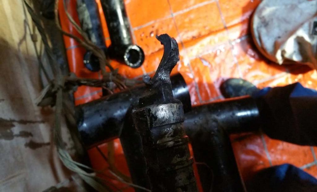
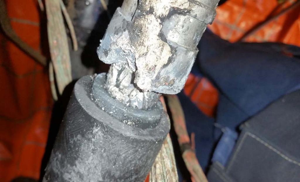
23 Example #1: Profile 3 Success UFO: Yesterday we had an outage with no cause determined. Today, we had another outage, currently patrolling again. Same devices tripped with profile 3 enabled. Outage Cause: Broken strand of AWAC Isolation Devices: R1 & R2 Investigation: Both R1 and R2 tripped and saw targets on A & B. Both devices were set to profile 3 and the fault current for A & B was greater than 400A UFO: No 12kV Sub R1 R2 2 65A 2 25A

24 Example #1: Profile 3 Success
25 Example #2: Profile 3 Frustration UFO: SCADA Device tripped on unbalance. Grid reports TL tripped open at same time. Full patrol will have to wait for daylight. Outage Cause: Phase Ground Fault on 69kV System Isolation Devices: R1 & R2 Investigation: Both R1 and R2 tripped on unbalance UFO: Yes 69/12kV Sub R1 R2
26 Example #2: Profile 3 Frustration 26
27 Example #3: Advanced SGF Frustration Investigation: Feeder tripped via electromechanical relays and locked out (went through it s full reclosing cycle). At the same time, neighboring circuits saw outages: R1 and R2 tripped and locked out on Advanced SGF targets due to bus voltage fluctuations. These reclosers were downstream of the fault. The cause of the outage was bad tees in a man hole, which all three circuits share in common. Reclosers tripped on DCD (fundamental frequency and THD). Outage Cause: Bad Tees Isolation Devices: Feeder CB, R1, R2 UFO: Yes R1 Sub MH R2

28 Example #3: Advanced SGF Frustration Fault location R2 R1 Cir1: 9.1% OH / 89.9% UG Cir2: 22.3% OH / 77.7% UG Cir3: 40.0% OH / 60% UG
29 Example #3: Advanced SGF Frustration
30 Example #3: Advanced SGF Frustration
31 Example #3: Advanced SGF Frustration


32 Example #3: Advanced SGF Frustration
33 Example #4: Falling Conductor Protection Investigation: FCP trip occurred. It was raining at the time and this is suspected to be related. ETS patrolled and no damage was found. Comm was noticed to be going in and out. There were data gaps but not during the event. The cause appears to be a faulty voltage sensor that reported a sharp change in voltage. Outage Cause: FCP Trip on V0 Faulted Sensor Isolation Devices: CB, R1 Follow Up: Short term solution is to raise the voltage threshold(s) in the field. Long term we will need to get a better sensor. UFO: Yes
34 Example #4: Falling Conductor Protection PV LINE MONITOR RECLOSER RECLOSER Zone 3 Zone 2 TRAYER Vz N.O. Vy Vy Vz VOLTAGE REG Zone 1 Vv IR Zone 4 CB SUBSTATON 34

35 Example #4: Falling Conductor Protection No high current change fluctuation was detected at any of the SCADA devices that could have caused the sudden drop in voltage on B phase

36 Example #4: Falling Conductor Protection Voltage differences between line and load sensors for reclosers, including a drop on B phase on the z side of R

37 Example #4: Falling Conductor Protection The drop in the voltage on B phase at recloser 1 caused the zero sequence voltage to trip above the pickup value of 400V

38 Example #4: Falling Conductor Protection Voltage on multiple MVRs in area show similar issues during rain.


39 Elimination of ALL risk is impossible Selectivity Security Adv.SGF Multiple SRs AE FCP IT FLISR Speed Profile 3/HLT SGF TCC Sensitivity Simplicity 39
Microgrid Fault Protection Based on Symmetrical and Differential Current Components
 Microgrid Fault Protection Based on Symmetrical and Differential Current Components Prepared for Public Interest Energy Research California Energy Commission Prepared by Hassan Nikkhajoei and Robert H.
SEL Arc-Flash Solutions
 SEL Arc-Flash Solutions Arc-Flash Protection at the Speed of Light Protect personnel and equipment Detect arc-flash events and send a trip signal in as little as 2 ms to enhance safety and minimize equipment
SEL Arc-Flash Solutions
 SEL Arc-Flash Solutions Arc-Flash Protection at the Speed of Light Protect personnel and equipment. Detect arc-flash events and send a trip signal in as little as 2 ms to enhance safety and minimize equipment
Distribution Control Center Operator Training
 Distribution Control Center Operator Training OnlineTraining 15-Hour Course COURSE I BASIC DISTRIBUTION 1. Introduction to Distribution Systems a. Terminology b. Basic electricity and Ohm s Law c. BES
What Utility Analytics means to Exelon
 What Utility Analytics means to Exelon Presented by Bart Enright IT Director Smart Grid Initiatives at ComEd Exelon s Analytic Journey Exelon Utilities Overview T&D Grids Data Visualization Data Analytics/Notifications
1S25. Arc Fault Monitor 4 Zones, 8 Sensors. Features. Introduction. ARC Fault Protection
 Technical Bulletin Arc Fault Monitor 4 Zones, 8 Sensors Features Four independent arc fault tripping zones 1 or 2 arc fault sensors per zone allowing up to 8 arc fault sensors per module Trip indication
Transmission Line Protection End to End Testing
 Transmission Line Protection End to End Testing Hands on Relay School, March 15, 2018 Chris Gallacher Protection Engineer Greg Sharpes Senior Relay Technician Mark Babin Senior Relay Technician Presentation
Electrical Energy department
 Al-Balqa Applied University Power systems Protection course Dr Audih al-faoury Electrical Energy department 2018-2019 Department of Electrical Energy Engineering 1 Part 1 Power System protection Introduction
SENTINEL D - Fault Passage Monitoring
 SENTINEL D - Fault Passage Monitoring DIRECTIONAL FAULT PASSAGE INDICATORS FOR OVERHEAD MV NETWORKS Installed on poles of overhead lines, the Overhead-Sentinel-D range allows locating the fault arisen
TRANSMISSION ENGINEERING STANDARDS SUBSTATIONS
 This standard was reviewed and approved by key managers on September 6, 2011. Officer approval of this revision is not required. 1.0 SCOPE 1.1 This guide applies to the interconnection of a Utility with
7XG3120 ReyArc20 Arc Fault Monitor Relay Energy Management
 Reyrolle Protection Devices 7XG3120 ReyArc20 Arc Fault Monitor Relay Energy Management 7XG3120 - Arc Fault Monitor Relay The over-current caused by an arc is, due to its resistance, lower than the over-current
AQ 100 Series. Arc Flash Protection System
 AQ 100 Series Arc Flash Protection System THE CONSEQUENCES OF AN ARC FAULT IN HIGH VOLTAGE SWITCHGEAR THE CONSEQUENCES OF AN ARC FAULT IN OIL-FILLED SWITCHGEAR Arc Phenomena Arc Phenomena Arc fault - facts
SENTINEL A - Fault Passage Indicator
 SENTINEL A - Fault Passage Indicator AMPEREMETRIC FAULT PASSAGE INDICATORS FOR OVERHEAD MV NETWORKS Installed on poles of overhead lines, the Overhead-Sentinel-A range allows locating the fault arisen
Major Fault Caused by Stator Winding Circuit Ring Failure
 Case study Major Fault Caused by Stator Winding Circuit Ring Failure Joël Pedneault-Desroches, P. Eng. Presentation Outline Introduction Inspection report Chronology of events Repair Conclusion 2 Introduction
VAMP 120 & 121. Arc flash detection units. Product picture
 Arc flash detection units VAMP 120 and 121(D) are extremely fast arc flash detection units for LV and MV switchgear and controlgear. The units are especially designed to increase the safety and to minimize
Communications Point Data Base for Communications Protocol IEC
 Switchgear Technical Data TD280017EN Effective July 2015 Supersedes R280-90-36 8/2012 Communications Point Data Base for Communications Protocol IEC60870-5 For use with Eaton s Cooper Power series Form
Installation, Operating and Maintenance Manual
 STATUS ZONES CONTROLS FIRE FAULT DISABLED FIRE 1 2 3 4 5 6 7 8 TEST FAULT DISABLED 1 5 BUZZER SILENCE RESET 1 2 TEST 2 6 LAMP TEST 3 SUPPLY 3 7 SYSTEM FAULT 4 8 SOUNDERS ACTIVATE/ SILENCE 4 FAULTS INSTRUCTIONS
HOKKIM INTEGRATED AMF CONTROL BOARD MANUAL FOR MODELS: HAMF-8 AND HAMF-4
 HOKKIM INTEGRATED AMF CONTROL BOARD MANUAL FOR MODELS: HAMF-8 AND HAMF-4 INTRODUCTION Thank you for purchasing the Hokkim Integrated Automatic Mains Failure Control Board model HAMF- 8 or HAMF-4. We shall
Fault Indicators for the Safe, Reliable, and Economical Operation of Modern Power Systems
 Fault Indicators for the Safe, Reliable, and Economical Operation of Modern Power Systems 2010 Schweitzer Engineering Laboratories, Inc. All rights reserved Table of Contents Fault Indicators for the Safe,
PGR-8800 TECHNICAL FAQ
 PGR-8800 SOLAR ARC-FLASH PRODUCTS RELAY CATALOG TECHNICAL FAQ What are the typical applications / system voltages? The PGR-8800 can be used on electrical systems operating at any voltage (AC or DC) since
Guide Specification Model CTG Automatic Transfer Switch
 Guide Specification Model CTG Automatic Transfer Switch PART 1 GENERAL 1.1 Scope A. It is the intent of this specification to secure a transfer switch that has been prototype tested, factory built, production
PNC 1000 SERIES 2, 4, 8 Zone Fire Alarm Control Panel
 PNC 1000 SERIES 2, 4, 8 Zone Fire Alarm Control Panel INSTALLATION, OPERATION AND MAINTENANCE MANUAL Version: CN-PM-1000.VER1.1-12/2012 EN54 INFORMATION In accordance with EN 54-2 clause 13.7, the maximum
TRANSMISSION ENGINEERING STANDARDS SUBSTATIONS
 This standard was reviewed and approved by key managers with final approval by an officer of Oncor Electric Delivery on. 1.0 SCOPE 1.1 This guide applies to the interconnection of a Customer with the Company
CIRCUIT BREAKER FAIL PROTECTION
 CIRCUIT BREAKER FAIL PROTECTION This document is for Relevant Electrical Standards document only. Disclaimer NGG and NGET or their agents, servants or contractors do not accept any liability for any losses
VAmP 120. Arc Flash Protection Units. Arc Protection. Customer benefits
 Arc Protection 01 VAmP 120 Arc Flash Protection Units Customer benefits Personnel Safety A fast and reliable arc protection unit may save human lives in case of an arc fault arising in a switchgear during
Lecture 4 Power System Protection. Course map
 Lecture 4 Power System Protection 1 Course map 2 1 Outline of the Lecture Relays and IEDs Protection Principles Protection requirements Protection Schemes 3 What can we control? Breakers Valves Tap changers
FCR 05, FCR 07. Power factor correction controller. User and service manual
 FCR 05, FCR 07 Power factor correction controller User and service manual version 2.3 Czech Republic Czech Republic 1 Content 1. Control and signal elements... 3 2. Device description... 4 3. Instruction
Palak Parikh, Lalit Lopez GE Digital Energy. Acknowledgment: Scottish and Southern Energy(SSE)
") Palak Parikh, Lalit Lopez GE Digital Energy Acknowledgment: Scottish and Southern Energy(SSE) Outline Why LV network monitoring? Challenges and Opportunities LV Monitoring Node Architecture Advance LV
Palak Parikh, Lalit Lopez GE Digital Energy Acknowledgment: Scottish and Southern Energy(SSE) Outline Why LV network monitoring? Challenges and Opportunities LV Monitoring Node Architecture Advance LV
TELECOMMUNICATION EQUIPMENT LOCATED IN THE VICINITY OF PROPOSED DISTRIBUTION HV EARTHS
 Network Asset Technical Document TELECOMMUNICATION EQUIPMENT LOCATED IN THE VICINITY OF PROPOSED DISTRIBUTION HV EARTHS Original Issue: August 2006 Prepared by: M. Lamparski This Revision: Rev 1 October
Three Terminal 230kV System Protection and Restoration at Calpine s Creed and Goose Haven Energy Centers Suisun City, California
 Three Terminal 230kV System Protection and Restoration at Calpine s Creed and Goose Haven Energy Centers Suisun City, California Larry Henriksen POWER Engineers, Inc. Hailey, Idaho Daren Phelps Calpine
Brown University Revised June 29, 2012 Facilities Design & Construction Standards SECTION ELECTRICAL DESIGN CRITERIA
 PART 1 - GENERAL 1.1 Background SECTION 26 00 10- ELECTRICAL DESIGN CRITERIA A. Brown University maintains it own campus electrical distribution system which serves the majority of the buildings and facilities
Table of Contents. Protective Relays
 Table of Contents KILOVAC WD Series, DIN Rail or Screw Mounted Introduction..........................................................11-2 KILOVAC WD25 Paralleling Relays........................................11-3
VAMP 120 & 121. Arc Flash Protection Units. Arc Protection. Customer benefits
 01 VAMP 120 & 121 Arc Flash Protection Units Customer benefits Personnel Safety A fast and reliable arc protection unit may save human lives in case of an arc fault arising in a switchgear during work
Root Cause Analysis Report Tesoro Golden Eagle Refinery Refinery Power Outage
 Summary of Event: The Golden Eagle Refinery (Refinery) experienced a partial electrical outage December 10, 2010 at 10:12 hrs when a transformer at Switching Station #7 failed. A CWS Level 1 report was
Moulded case circuit brakers
 Moulded case circuit brakers CONTENT Range 1 Protection Releases 2 Salient Features 5 Accessories 7 Widest Range 10 Time Current Characteristics 12 Overall Dimensions 14 SN4 SN3 SN2 SN1 3 RANGE SN1 Rated
Synchrophasor Technology in Control Centers Clemson University, SC March 12, 2014 Vikram S. Budhraja
 Clemson University Power Systems Conference Synchrophasor Technology in Control Centers Clemson University, SC March 12, 2014 Vikram S. Budhraja Outline Synchrophasor Technology Infrastructure Lessons
To: Honorable Public Utilities Board Submitted by: /s/ Douglas Draeger AGM Engineering and Operations
 AGENDA ITEM NO.: 5.D.1 MEETING DATE: 0/4/014 ADMINISTRATIVE REPORT NO.: 014-48 To: Honorable Public Utilities Board Submitted by: /s/ Douglas Draeger AGM Engineering and Operations From: Tito R. Nagrampa
APPLICATION NOTE. Applying pressure sensing in arc flash protection applications with air magnetic circuit breakers
 APPLICATION NOTE Applying pressure sensing in arc flash protection applications with air magnetic circuit breakers Application note Applying pressure sensing in arc flash protection 2 (6) Revision 1.0
Event Detection System (EDS)
") WaveGrid Event Detection System (EDS) Installation, Operations and Maintenance Guide Control Module Revision 6.0 June 24 th, 2016 Sensor Module I Functional Description The Event Detection System (EDS)
WaveGrid Event Detection System (EDS) Installation, Operations and Maintenance Guide Control Module Revision 6.0 June 24 th, 2016 Sensor Module I Functional Description The Event Detection System (EDS)
End To End Optical Beam Smoke Detector. Additional Information
 End To End Optical Beam Smoke Detector Additional Information EN 1. Multiple Zone Wiring When using more than one System Controller on a single zone of a conventional Fire Control Panel (FCP), it is important
Intelligent Security & Fire Ltd
 OPERATIONAL NOTES FOR CONCEPT FIRE PANEL. NOTE ON NEW FIRE PANELS, POSITION 1 ON THE SIX WAY INTERNAL OPTION SWITCH IS TURNED ON, DISABLING THE ZONAL SOUNDERS. TO ENABLE ZONAL SOUNDERS TURN OFF. Operation
NextGen SCADA Europe 2013
 NextGen SCADA Europe 2013 Thursday 21st & Friday 22nd March 2013 Holiday Inn Amsterdam, Netherlands Brian Tapley Manager, HV Operations, North Distribution Control Centre, Ireland 1 Presentation Overview
Standard PRC Transmission Relay Loadability
 A. Introduction 1. Title: Transmission Relay Loadability 2. Number: PRC-023-2 3. Purpose: Protective relay settings shall not limit transmission loadability; not interfere with system operators ability
CITY OF WHITEHORSE SERVICING STANDARDS MANUAL SECTION 2 - CONSTRUCTION DESIGN CRITERIA SUB-SECTION 2.A SCADA STANDARDS.
 CITY OF WHITEHORSE SERVICING STANDARDS MANUAL SECTION 2 - CONSTRUCTION DESIGN CRITERIA SUB-SECTION 2.A SCADA STANDARDS Table of Contents 2.A.1 SCADA Standards 2.5-2 2.A.1.1 Generators 2.5-2 2.A.1.2 Building
FlameGard 5 MSIR HART
 FlameGard 5 MSIR HART Multi-Spectral Infrared Flame Detector HART Communication with the FlameGard 5 Multi-spectral Infrared Detector The information and technical data disclosed in this document may be
Description (Data Point Name) Unit Size
 Unit Size") AC-PRO-II Communications Modbus Register Map Document Revision 2.0 Firmware v2.0 AC-PRO-II: Registers 7000 7019: Output Coils 7020 7099: Information 7107 7199: User settings (can be set using Modbus Communications)
AC-PRO-II Communications Modbus Register Map Document Revision 2.0 Firmware v2.0 AC-PRO-II: Registers 7000 7019: Output Coils 7020 7099: Information 7107 7199: User settings (can be set using Modbus Communications)
SECTION AUTOMATIC TRANSFER SWITCHES
 SECTION 26 36 23 AUTOMATIC TRANSFER SWITCHES PART 1 - GENERAL 1.1 RELATED DOCUMENTS A. General provisions of the Contract, including General and Supplementary Conditions and Division 01 Specification Sections,
ICS Regent. Fire Detector Input Modules PD-6032 (T3419)
") ICS Regent Fire Detector Input Modules (T3419) Issue 1, March, 06 Fire detector input modules provide interfaces for 16 fire detector inputs such as smoke detectors, flame detectors, temperature detectors,
ICS Regent Fire Detector Input Modules (T3419) Issue 1, March, 06 Fire detector input modules provide interfaces for 16 fire detector inputs such as smoke detectors, flame detectors, temperature detectors,
MAINTENANCE OF LV SWITCHGEAR SECTOR / ENGINEERING TECHNICAL & CERTIFIED TRAINING COURSE
 SECTOR / ENGINEERING TECHNICAL & CERTIFIED TRAINING COURSE Switchgear is a general term used for any devices that breaks and makes the electrical circuit and covers right from a typical piano switch used
FlameGard 5 UV/IR HART
 FlameGard 5 UV/IR HART HART Communication Manual The information and technical data disclosed in this document may be used and disseminated only for the purposes and to the extent specifically authorized
2000 Series. Program Entry Guide. Control Panels
 2000 Series EN Program Entry Guide Control Panels 2000 Series Program Entry Guide About This Manual EN 2 About This Manual This guide describes the programming parameters available to the 2000 Series Control
CONTACTORS FOR AEROSPACE GROW SMARTER AND MORE CAPABLE
 CONTACTORS FOR AEROSPACE GROW SMARTER AND MORE CAPABLE Karl Kitts, Director of Development Engineering for High Performance Relays AEROSPACE, DEFENSE & MARINE /// WHITE PAPER - CONTACTORS FOR AEROSPACE
M2500 Engine Controller Installation Manual
 M2500 Engine Controller Installation Manual Revision: 23-04-2012 Page 1 Contents 1 Preface... 4 2 Installation... 5 3 Terminal Connections... 6 4 Inputs... 7 4.1 Power Supply... 7 4.2 Mode/ Control Inputs...
Changes to NFPA 70E. - The Role of PdM &Safe PdM Work Practices. Tim Rohrer Exiscan LLC
 Changes to NFPA 70E - The Role of PdM &Safe PdM Work Practices Tim Rohrer Exiscan LLC Tim@Exiscan.com 585-705-7775 Joe Gierlach ABM Joseph.Gierlach@ABM.com 412-394-4678 Preview Electrical Safety Risk Management
Power System Protection Part 2 Dr.Prof. Mohammed Tawfeeq. Zones of Protection
 84 Power System protection Dr. Mohamad Tawfeeq Zones of protection Zone of protection of a relay is the place or the distance that the relay can protect easily.fig.1 shows an example of protection zones
National Grid / DG Installation Process Guide per NY SIR / July 2011 ver. 1.0
 Distributed Generation Installation Process Guide for Connections to National Grid Distribution Facilities per the New York Standardized Interconnection Requirements Introduction National Grid ( The Company
Electric Power Group Presents. Welcome!
 Electric Power Group Presents Maximizing Use of Synchrophasor Technology for Everyday Tasks Welcome! The meeting will begin at 2:00 p.m. ET / 11:00 a.m. PT Jan. 18, 2017 Today s Topic: Synchrophasor Intelligence
BE1-50/51B with S1 Case or FT-11 sized Case and Cover For non-retrofit applications, see Product Bulletin UHD.
 BE1-50/51B SELF POWERED TIME OVERCURRENT RELAY RETROFIT KITS BE1-50/51B with S1 Case or FT-11 sized Case and Cover For non-retrofit applications, see Product Bulletin UHD. BE1-50/51B, CO Retrofits BE1-50/51B,
VERTEX VT10 SERIES PID OPERATION MANUAL MICROPROCESSOR BASED PID CONTROLLER
 1 VERTEX VT10 SERIES PID OPERATION MANUAL MICROPROCESSOR BASED PID CONTROLLER 1. INTRODUCTION This manual contains information for the installation and operation and tuning of our Vertex VT10 series self-tuning
Development of standards for MV Switchgear for Arc Flash protection. ABB Group May 20, 2013 Slide 1
 Development of standards for MV Switchgear for Arc Flash protection May 20, 2013 Slide 1 Development of standards for MV Switchgear for Arc Flash protection Bryan Johnson ABB South Africa Shaping the world
Ground Fault Protection Improvement Study
 Ground Fault Protection Improvement Study Greg Ball DNV KEMA Solar ABCs Stakeholder Meeting July 11, 2013 San Francisco, CA Study Authors 2 Bill Brooks Brooks Engineering Andy Rosenthal New Mexico State
Surface Acoustic Wave Technology based Temperature Monitoring of High Voltage and High Current Switchgear Boxes
 Surface Acoustic Wave Technology based Temperature Monitoring of High Voltage and High Current Switchgear Boxes Summary Safety is a big concern when it comes to managing power distribution systems. High
Detailed Instructions
 Introduction Timer is a versatile, rugged, and easy to use indoor / outdoor appliance timer. It can be used with lights and other household appliances that require regular on-off cycles and has two main
NFPA 70E Arc Flash Considerations for MV Equipment. By: Dominik Pieniazek, P.E. HV Engineering, LLC
 NFPA 70E Arc Flash Considerations for MV Equipment By: Dominik Pieniazek, P.E. dominik@hv-eng.com HV Engineering, LLC http://sites.ieee.org/houston/ Full link for PDF copies of presentations: http://sites.ieee.org/houston/communities/ie
Oven Control System Operation - Ver 2.8
 Version 2.8 - Pg:1 - Ver 2.8 This operation manual contains important information about your oven. All operators should review this manual before operating the oven. When you turn on the switch, the control
Solid State Relays SOLITRON MIDI Current Sensing Type RJCS, RJCSR
 Solid State Relays SOLITRON MIDI Current Sensing Type, R AC semiconductor contactor Integrated current monitoring Zero switching (1A) Direct copper bonding (DCB) technology LED-indication Cage clamp output
THERMAL DIAGNOSIS OF MV SWITCHBOARDS: A COST-EFFECTIVE, DEPENDABLE SOLUTION BASED ON AN OPTICAL SENSOR
 THERMAL DIAGNOSIS OF MV SWITCHBOARDS: A COST-EFFECTIVE, DEPENDABLE SOLUTION BASED ON AN OPTICAL SENSOR Christian PETIT Anticipation manager Schneider Electric - Network protection and control unit -Marketing
Relay Performance Index for a Sustainable Relay Replacement Program
 Relay Performance Index for a Sustainable Relay Replacement Program Aaron Feathers, Abesh Mubaraki, Nai Paz, Anna Nungo Pacific Gas & Electric Company San Francisco, CA Western Protective Relay Conference
Guide to Transmission Equipment Maintenance
 Guide to Transmission Equipment Maintenance March 2018 Revision History Issue Date Update 1 September 2013 First Issue 2 March 2016 Updated in response to SEM-15-071 Decision Paper Outturn Availability.
Operation and use. Functions and characteristics
 Operation and use Function Vigirex relays measure the earth-leakage current in an electrical installation via their associated toroids. Vigirex relays may be used for: b residual-current protection (RH10,
EUROBOX SERIES TYPES CM... SM... MM...
 EUROBOX SERIES TYPES CM... SM... MM... AUTOMATIC GAS BURNER CONTROL SYSTEMS FOR GAS BURNERS AND GAS BURNING APPLIANCES WITH OR WITHOUT FAN Application This range of electronic gas burner control systems
PowerLogic ION Setup Meter Configuration Software Configuration Guide
 PowerLogic ION Setup Meter Configuration Software Configuration Guide 70002-0293-03 12/2010 Conventions Used in this Manual This section describes the symbols and terminology used in this guide. Symbols
INSPECTION AND TESTING OF ELECTRICAL INSTALLATIONS: RESIDUAL CURRENT DEVICES
 INSPECTION AND TESTING OF ELECTRICAL INSTALLATIONS: RESIDUAL CURRENT DEVICES [The basis of this article was first published in Wiring Matters in issue 15, Summer 2005 and reflected the requirements of
Warehouse Protection of Exposed Expanded Group-A Plastics with Electronic Sprinkler Technology
 Warehouse Protection of Exposed Expanded Group-A Plastics with Sprinkler Technology Zachary L. Magnone, Jeremiah Crocker, Pedriant Peña Tyco Fire Protection Products, Cranston, RI, USA Abstract The focus
T22 - Arc Flash Hazards and Arc Resistant Equipment- Understanding the Standards
 T22 - Arc Flash Hazards and Arc Resistant Equipment- Understanding the Standards v2-5058-co900h Copyright 2016 Rockwell Automation, Inc. All Rights Reserved. 1 Agenda 1. Background 2. Related Electrical
Syncro AS. Analogue Addressable Fire Control Panel. User Manual
 Syncro AS Analogue Addressable Fire Control Panel User Manual Man-1100 Issue 02 Nov. 2008 Index Section Page 1. Introduction...3 2. Safety...3 3. Panel Controls...4 3.1 Access Level 1...4 3.2 Access Level
SECTION AUTOMATIC TRANSFER SWITCHES
 PART 1 - GENERAL 1.1 DESCRIPTION SECTION 26 36 23 This section specifies the furnishing, complete installation, and connection of automatic transfer switches. 1.2 RELATED WORK A. Section 14 21 00, ELECTRIC
Lago SD3. Differential Controller with Speed Control. Operating and Installation Instructions
 Lago SD3 Differential Controller with Speed Control Operating and Installation Instructions Please observe the safety instructions and read through this manual carefully before commissioning the equipment.
Flostop TS D7E and A8E. Operation Manual
 Flostop TS D7E and A8E Operation Manual United Kingdom Spectron Gas Control Systems Ltd, Unit 4, ATU1, University of Warwick science Park, Coventry, +44 (0) 24 7641 6234 sales@spectron-gcs.com Germany
COCB_ Circuit Breaker (2 state inputs/ 2 control inputs)
") MRS752348-MUM Issued: 0/997 Version: F/23.6.2005 Data subject to change without notice COCB_ Circuit Breaker (2 state inputs/ 2 control inputs) Contents. Introduction... 3. Features... 3.2 Application...
MRS752348-MUM Issued: 0/997 Version: F/23.6.2005 Data subject to change without notice COCB_ Circuit Breaker (2 state inputs/ 2 control inputs) Contents. Introduction... 3. Features... 3.2 Application...
Ground Fault Protection Improvements to Prevent Fires Description of problem and potential solutions Presented by Bill Brooks, PE Principal, Brooks
 Ground Fault Protection Improvements to Prevent Fires Description of problem and potential solutions Presented by Bill Brooks, PE Principal, Brooks Engineering Code Official Panel Lead, SolarABCs 1 Ground-Fault
M O T I O N DETECTORS. The Paradox series of motion detectors. combines advanced features and patented. technologies to provide a high level of
 M O T I O N DETECTORS The Paradox series of motion detectors combines advanced features and patented technologies to provide a high level of detection and false alarm prevention. Whatever the application,
FACILITY CONNECTION STANDARD
 FACILITY CONNECTION STANDARD Preface: This Facility Connection Standard applies to any connection to the electric system of Westar Energy, Inc. or Kansas Gas and Electric Company, both doing business as
GPS 140 NEC Requirements for Generators. Professional Development Seminar Series NEC Requirements for Generators
 GPS 140 NEC Requirements for Generators WHAT YOU WILL LEARN NEC requirements for on-site power generation. Recent events have created increased interest in standby power This module organizes NEC requirements
Contents. Preface. Chapter 2 Faults, types and effects The development of simple distribution systems Faults-types and their effects 7
 Practical Power System Protection for Engineers and Technicians Contents Preface ix Chapter 1 Need for protection 1 1.1 Need for protective apparatus 1 1.2 Basic requirements of protection 2 1.3 Basic
Applications and Discussions of Arc Flash Protection Relay as a Main Busbar Protection in MV Switchboards
 Applications and Discussions of Arc Flash Protection Relay as a Main Busbar Protection in MV Switchboards LIN ZHOU M Eng, MIEAust RIZNER Australia YANG YIJUN B. Eng, Senior Engineer State Grid, Zhejiang
Total Connect Box. User manual
 Total Connect Box User manual 1 Congratulations on your purchase of the Honeywell Total Connect Box security system. To make the best out of your system we advise you to read this manual carefully. This
DKG-108 POWER FACTOR CONTROLLER
 DKG-108 POWER FACTOR CONTROLLER 8 BANKS, HARMONIC DISTORTION DISPLAY FEATURES Small size Cost effective and high performance True RMS AC measurements,high accuracy 4096 samples/sec measurement rate Easy
5. CBS Alarms Responding to a CBS Alarm Understanding the Alarm Condition A-CBS-008 Circuit Breaker Sentinel Page 109 of 156
 Page 109 of 156 5. CBS Alarms 5.1. Responding to a CBS Alarm The CBS uses its alarm contacts to signal the presence of alarm conditions. There are two alarm relays:one for Caution alarms and one for Problem
NFPA Edition Review
 This is a photographic template your photograph should fit precisely within this rectangle. NFPA 70 & 99 How Recent Code Changes Effect Healthcare Facilities Sam C. Terry, P.E. Application Engineer Eaton
Division 26 ELECTRICAL TABLE OF CONTENTS
 Division 26 ELECTRICAL TABLE OF CONTENTS 26 1000 GENERAL... 33 A. CODE... 3 B. RELATED SECTIONS... 3 C. ABBREVIATIONS... 3 D. DEFINITIONS... 3 E. DRAWING REQUIREMENTS... 3 F. EQUIPMENT SERVICE ACCESS AND
38-SDMS-04 REV. 0 SPECIFICATION FOR ANNUNCIATOR SYSTEMS FOR PRIMARY DISTRIBUTION SUBSTATION
 38-SDMS-04 REV. 0 SPECIFICATION FOR ANNUNCIATOR SYSTEMS FOR PRIMARY DISTRIBUTION SUBSTATION This specification is property of SEC and subject to change or modification without any notice. TABLE OF CONTENTS
Results of Recent DOE Research on Development of Cable Condition Monitoring and Aging Management Technologies
 Results of Recent DOE Research on Development of Cable Condition Monitoring and Aging Management Technologies C.J. Campbell, J.B. McConkey, H.M. Hashemian, C.D. Sexton, D.S. Cummins Analysis and Measurement
Continuous, real-time detection, alarming and analysis of partial discharge events
 DMS PDMG-R Partial discharge monitor for EHV GIS Continuous, real-time detection, alarming and analysis of partial discharge events Automatic PD fault classification Robust design allows for reliable operation
M2000 Engine Controller
 M2000 Engine Controller Integrated control and protection of diesel and gas engines for all purposes Especially suited for auxiliary generator sets 1 IN OPERATION 1 2 STARTFAIL 2 3 OVERSPEED RPM FAIL 3
Energy Saving Drives for Hot Strip Mills
 Energy Saving Drives for Hot Strip Mills Ralph PUGH TMEIC 060 Cook Drive Salem, VA 4153, USA Tel: 540-83-158 Fax: 540-83-395 E-mail: ralph.pugh@tmeic.com Serkay ÖZALICI TOSÇELIK Osmaniye OSB Turkey Tel:
LineVision TM. Non-Contact Transmission Line Monitoring and Dynamic Line Rating
 LineVision TM Non-Contact Transmission Line Monitoring and Dynamic Line Rating Jonathan Marmillo, Business Development M: 484-368-4630 E: jmarmillo@genscape.com www.genscape.com 2017 Genscape Incorporated.
I/O ZONE 560/583 AND OPERATION MANUAL
 UPM I I/O ZONE 560/583 INSTALLATION AND OPERATION MANUAL 1 UNIT PROTECTION MODULE HARDWARE OPERATION IMPORTANT: This manual is for UPM board part numbers 8733 800 259. See controller label as shown in
Motor Controller AC Semiconductor Motor Controller Type RSBS23..A2V.2C24..
 Motor Controller AC Semiconductor Motor Controller Type RSBS23..A2V.2C24.. Soft starting of 1-Phase Scroll Compressors Enclosed solution Integrated current limit Rated operational voltage: 230 VACrms,
Dual Technology Wall Switch Occupancy Sensor. Manual & Specification
 Dual Technology Wall Switch Occupancy Sensor Manual & Specification PRODUCT MUST BE INSTALLED IN ACCORDANCE WITH LOCAL ELECTRICAL CODES Douglas Lighting Controls Page 1 November 19, 2014 1. INTRODUCTION