ATR 171. Regolatore Controller Manuale Installatore User manual
|
|
|
- Madeline Parrish
- 5 years ago
- Views:
Transcription

1 ATR 171 Regolatore Controller Manuale Installatore User manual
2 Summary Page 1 Introduction 4 2 Model Identifi cation 4 3 Technical Data General data Hardware data Software data 6 4 Dimensions and Installation 6 5 Electrical wirings Wiring diagram 7 6 Display and Key Functions Numeric Indicators (Display) Meaning of Status Lights (Led) Keys 15 7 Dual input mode (only for ATR171-23ABC-T) Selection of process value related to the command output and to the alarms Remote setpoint 17 8 Controller Functions Modifying Main Setpoint and Alarm Setpoint Values Auto-Tuning Manual Tuning Automatic Tuning Soft-Start Automatic / Manual Regulation for % Output Control Pre-Programmed Cycle Memory Card (optional) Loading default values LATCH ON Function Timer function Digital input functions (only for ATR171-11/12/14ABC) Dual Action Heating-Cooling 24 9 Serial Communication (only for ATR171-23ABC-T) Modbus RTU Confi guration Modify Confi guration Parameter Table of Confi guration Parameters Alarm Intervention Modes Table of Anomaly Signals Summary of Confi guration parameters 50 Pay attention at the section marked with this symbol Presta attenzione alla sezione contrassegnata da questo simbolo
3 Sommario Pag. 1 Introduzione 54 2 Identifi cazione di modello 54 3 Dati tecnici Caratteristiche generali Caratteristiche Hardware Caratteristiche Software 56 4 Dimensioni e installazioni 56 5 Collegamenti elettrici Schema di collegamento 57 6 Funzione dei visualizzatori e tasti Indicatori numerici (Display) Signifi cato delle spie di stato (Led) Tasti 65 7 Modalità doppio ingresso (solo per ATR171-23ABC-T) Selezione grandezza correlata al comando e agli allarmi Setpoint remoto 67 8 Funzioni del regolatore Modifi ca valore setpoint principale e setpoint di allarme Auto-Tuning Lancio del Tuning Manuale Tuning Automatico Soft-Start Regolazione automatico / manuale del controllo % uscita Ciclo pre-programmato Memory Card (opzionale) Caricamento valori di default Funzione LATCH ON Funzionamento timer Funzioni da Ingresso digitale (solo per ATR171-11/12/14ABC) Funzioni in doppia azione (caldo-freddo) 74 9 Comunicazione Seriale (solo per ATR171-23ABC-T) Modbus RTU Confi gurazione Modifi ca parametro di confi gurazione Tabella parametri di confi gurazione Modi di intervento allarme Tabella segnalazioni anomalie Promemoria confi gurazione 100
4 1 Introduction Thanks for choosing a Pixsys controller. With ATR171 model, Pixsys integrates in a single device all options for sensors reading and actuators control, beside an useful supply with extended range Vac/Vdc. Thanks to 17 selectable probes and outputs confi gurable as relay or SSR, the user or the retailer can reduce stock needs. The series includes also a model with double analogue input, serial communication RS485 ModbusRTU and linear output 0-10 V, 0/4-20 ma. The possibility to repeat parameterization is simplifi ed by the Memory Cards with internal battery that do not require power supply for the controller. 2 Model identification ATR171 series includes four versions. Looking at the following table it is possible to fi nd the required model. Power supply Vac/Vdc +/-15% 50/60 Hz 5,5 VA ATR ABC ATR ABC 1 Analogue input + 1 Relay 8 A + 1 SSR 1 Analogue input + 2 Relays 8 A + 1 SSR ATR ABC 1 Analogue input + 3 Relays 8 A + 1 Relay 5 A (30 V) ATR ABC-T 2 Analogue input + 3 Relays 8 A 1 Output SSR/V/mA+ RS485 EN 4
5 3 Technical data 3.1 General data Indicators 4 display 0,50 inches 4 display 0,30 inches Operating Temperature Temperature 0-45 C Humidity ur% Sealing IP54 front panel, box IP30, terminal block IP20 Material Box: Noryl UL94V1 self-exstinguish Front panel: PC ABS UL94V0 self-exstinguish Weight Approx 250 g. 3.2 Hardware data Analogue imput Relay output SSR/V/mA output Supply AI1 - AI2: Confi gurable via software. Input: Thermocouple type K, S, R, J. Automatic compensation of cold junction from 0 50 C. Thermoresistances: PT100, PT500, PT1000, Ni100, PTC1K, NTC10K (β 3435K). - ONLY AI1 Input V/mA: 0-10 V, 0-20 or 4-20 ma, 0-40 mv. Input Potentiometer: 6 KΩ, 150 KΩ. Confi gurable as control and alarm output. 1 SSR - V/mA Confi gurable as control output, alarm, retransmission of process or setpoint. Extended range Vac/Vdc ±15 % 50/60 Hz. Tolerance (25 C) +/-0.2% ±1 digit for thermocouple, thermoresistance and V / ma. Cold junction accuracy 0.1 C/ C. Impedance: 0-10 V: Ri>110 KΩ 0-20 ma: Ri<5 Ω 4-20 ma: Ri<5 Ω 0-40 mv: Ri>1 MΩ Contacts: Q1, Q2, Q3: 8 A V~ for resistive charges; Q4: 5 A - 30 V for resistive charges. 12 Vdc / 30 ma. Confi gurable: V (9500 points); 0 20 ma (7500 points); 4 20 ma (6000 points). Consumption: 5.5 VA 5 EN
6 Software data Control algorithm Proportional band Integral time Derivative time ON - OFF with hysteresis. P., P.I., P.I.D., P.D. proportional time C or F 0, ,9 sec (0 excludes) 0, ,9 sec (0 excludes) Manual or automatic tuning, selectable alarms, Controller protection of control and alarm setpoints, functions function selection from digital input, start/stop preprogrammed cycle. 4 Dimensions and installation Memory Card (optional) with battery Cod. MEMORY C mm ATR171 PIXSYS 1 CN1 6 U1 6 C1 MEMORY C.241 CN1 1 Memory Card (optional) Cod. MEMORY C241 42mm inserimento Memory Card 42mm insert Memory Card 72 mm C1 A1 C2 A2 TUN A3 MAN REM RUN PRGM FNC 66 mm SET EN 6-10 ATR171-23ABC-T 1 SSR/V SUPPLY V 11 ma+ AC/DC 2 Q1 12 +Vdc 8A 3 13 AI2 230V 485-1/2HP TC AI1 Q2 8A 7 230V /2HP 8 TC V Q3 18 ma + 8A 9 230V 1/2HP DIMA DI FORATURA 66,5 x 66,5 mm Frontal panel cut-out 6 1 Memory Card Spessore suggerito Suggested thickness 2 8 mm 5 89 mm 10
7 5 Electrical wirings WARNING Although this controller has been designed to resist noises in an industrial environments, please notice the following safety guidelines: Separate control lines from the power wires. Avoid the proximity of remote control switches, electromagnetic meters, powerful engines. Avoid the proximity of power groups, especially those with phase control. 5.1 Wiring diagram Belon the wiring diagrams of the 4 available models SSR + - SUPPLY V AC/DC SSR + - SUPPLY V AC/DC Vdc DI Q1 8A 230V 1/2HP Vdc DI Q1 8A 230V 1/2HP AI TC V/mA AI1 - TC + Q2 8A 230V - 1/2HP V/mA ATR171-11ABC ATR171-12ABC 7 EN
8 TC Q4 5A 30V 1/8HP +Vdc DI AI1 - + SUPPLY V AC/DC Q1 8A 230V 1/2HP Q2 8A 230V 1/2HP - Q3 V/mA 8A 230V 1/2HP SSR/V ma + +Vdc AI TC 15 + AI TC 18 + SUPPLY V AC/DC Q1 8A 230V 1/2HP Q2 8A 230V 1/2HP - V/mA + Q3 8A 230V 1/2HP ATR171-14ABC ATR171-23ABC-T 1 2 AI1 17 Power Supply SUPPLY V AC/DC Analogue input AI1 18 TC Shield/Schermo Switching supply with exstended range Vac/dc ±15% 50/60 Hz 5,5 VA. For thermocouples K, S, R, J. Comply with polarity. For extensions make sure to use the correct extension/compensating cable. When shielded cable is used, it should be grounded at one side only. EN 8
9 AI AI Shield/Schermo Shield/Schermo PT/NI100 PTC/NTC For thermoresistances PT100, NI100. For a three-wires connection use cables with the same diameter. For a two-wires connection short-circuit terminals 16 and 18. When shielded cable is used, it should be grounded at one side only. RED WHITE RED For thermoresistances NTC, PTC, PT500, PT1000 and linear potentiometers. When shielded cable is used, it should be grounded at one side only AI1 Shield/Schermo +Vdc V ma For linear signals Volt / ma. Comply with polarity. When shielded cable is used, it should be grounded at one side only. Analogue input AI2 (only for ATR171-23ABC-T) To enable the second analogue input, set the dip switches as indicated in the figure. In this configuration the serial RS485 is not available. 9 EN
10 AI TC AI Shield/Schermo Shield/Schermo PT/NI100 For thermocouples K, S, R, J. Comply with polarity. When extending thermocouples be sure to use the correct extension/compensating cable. When shielded cable is used, it should be grounded at one side only. For thermoresistances PT100, NI100. For a three-wires connection use cables with the same diameter. For a two-wires connection short-circuit terminals 13 and 15. When shielded cable is used, it should be grounded at one side only. RED WHITE RED AI Shield/Schermo PTC/NTC For thermoresistances NTC, PTC, PT500, PT1000 and linear potentiometers. When shielded cable is used, it should be grounded at one side only Examples of connection for linear input V + - For linear signals 0.10 V. Comply with polarity. EN 10
11 18 C 17 B 12 A mA PRESSURE TRANSMITTER / SENSORE DI PRESSIONE 18 C 17 B mA External supply / Alimentazione esterna PRESSURE TRANSMITTER / SENSORE DI PRESSIONE 18 C 12 A mA PRESSURE TRANSMITTER / SENSORE DI PRESSIONE OUT : mA OUT : mA IN :9...33V DC OUT : mA IN :9...33V DC IN :9...33V DC P : mbar Pmax :3bar P : mbar P : mbar Pmax :3bar Pmax :3bar T :0..70 C T :0..70 C T :0..70 C For linear signals 0/4.20 ma with threewires sensors. Comply with polarity: A= Sensor supply B= Sensor ground C= Sensor output For linear signals 0/4..20 ma with external power supply for sensor. Comply with polarity: C= Sensor output B= Sensor ground For linear signals in current 0/4..20 ma with two-wires sensors. Comply with polarity: C= Sensor output A= Sensor supply Serial input (only for ATR171-23ABC-T) To enable the second analogue input, set the dip switches as indicated in the figure. In this configuration the second analogue input is not available Shield/Schermo RS485 Communication RS485 Modbus RTU. For networks with more than fi ve instruments supply in low voltage. 11 EN
12 Relay outputs Q1, Q2, Q3 Contacts capacity: 8 A, 250 Vac, resistive charge 10 5 operations; 30/3 A, 250 Vac, cosφ= 0.3, 10 5 operations Q1 8A 230V 1/2HP Q2 8A 230V 1/2HP Q3 8A 230V 1/2HP Relay output Q4 (only for ATR171-14ABC) Contacts capacity: 5 A, 30 Vac/dc, resistive 18x10 4 operations Q4 5A 30V 1/8HP EN 12
13 SSR output 10 SSR 11 SSR Command output 12 V / 30 ma Output ma / Volt (only for ATR171-23ABC-T) ma To use SSR output it is necessary to set channel 1 of DIP2 as indicated in the figure. Analogue output in ma confi gurable as command (Par. ) or retransmission of process-setpoint (Par. ). To use SSR output it is necessary to set channel 1 of DIP2 as indicated in the figure V Analogue output in Volt confi gurable as command (Par. ) or retransmission of process-setpoint (Par. ). To use SSR output it is necessary to set channel 1 of DIP2 as indicated in the figure Digital Input (only for ATR171-11/12/14-ABC) +Vdc DI Digital Input (Par. ). 13 EN
14 6 Display and keys functions ATR C1 A1 C1 A1 C2 A2 C2 A2 TUN A3 MAN REM RUN TUN A3 MAN REM RUN PRGM FNC SET Numeric indicators (Display) Normally displays the process. 1 During the confi guration phase, it displays the parameter being inserted. Normally displays the setpoint. 2 During the confi guration phase, it displays the parameter value being inserted. 6.2 Meaning of Status Lights (Led) On when command output is active. For open / 3 close logic: on during valve opening. 4 For open/ close logic: on during valve closing. 5 On when alarm 1 is active. 6 On when alarm 2 is active. 7 On when alarm 3 is active. 8 On when Manual function is active. EN 14
15 On when controller is executing an auto-tuning 9 cycle. 10 On when serial communication is in progress. 11 On when counting of Timer function is active. 6.3 Keys Increases main setpoint. In confi guration mode allows to scroll and modify parameters. Press after key increases alarm setpoints or time value of timer. Decreases main setpoint. In confi guration mode allows to scroll and modify parameters. Press after key decreases alarm setpoints or time value of timer. Allows to visualize alarm setpoints or time value of Timer. In confi guration mode allows to access the parameter to change and confi rm its modifi cation. Allows to enter tuning launch, selection automatic / manual. In confi guration mode operates as exit key (ESCAPE). If pressed allows to enter confi guration password. In confi guration mode assigns at selected parameter a mnemonic code or a number. Starts or stops timer counting. 15 EN
16 7 Dual input mode (only for ATR171-23ABC-T) To enable second input it is necessary to set dip switches as indicated in the fi gure. In this confi guration some parameters and functions are not available. For exemple: RS485 serial, preprogrammed cycle and soft-start function are desabled. 7.1 Selection of process value related to the command output and to the alarms When second input is enabled (parameter 9 other than ) it is possible to choose the process value to be related to command output, to alarms and to retransmission. Following options are available: : Value read by input AI1; : Value read by input AI2; : Mean between inputs AI1 and AI2; : Difference between inputs: AI1-AI2; : Difference between inputs AI1-AI2 as absolute value. Process related to command output must be set on parameter 15. Process related to alarms must be set on par. 34 for alarm 1, on par. 43 for alarm 2 and on par. 52 for alarm 3. Value to retransmit must be set on par. 79. It is possible to choose the visualization for display 2 on parameter 77. Mean and difference are available only if both inputs are configured for temperature sensors. EN 16
17 RT ATR171 FNC SET ATR171 FNC SET 7.2 Remote setpoint It is possible to enable remote setpoint function setting par. 16. REMOTE SETPOINT ATR171 OUT Control Loop on PRGM PROBE mA V ATR171 OUT REMOTE SETPOINT PRGM Control Loop PROBE In this confi guration the value read by one of the two inputs becomes the main control setpoint: If parameter 15 is set as, AI1 becomes the main process (command) and AI2 becomes the setpoint value; If parameter 15 is set as, AI2 becomes the main process (command) and AI1 becomes the setpoint value. Remote setpoint function works only with one of these two settings of parameter Controller functions 8.1 Modification of main and alarm setpoint value Setpoint value can be modified from keyboard as follows: Press Display Do 1 or Value on display 2 changes. Increase or decrease main setpoint value. 2 3 Visualizes alarm setpoint on display 1. or Value on display 2 changes. Increase or decrease alarm setpoint value. 17 EN
18 8.2 Auto-tuning Tuning procedure to calculate regulation parameters can be manual or automatic and selected from parameter Manual Tuning Manual procedure allows user more fl exibility on deciding when to update regulation parameters of P.I.D. algorithm. Press key until display 1 visualizes writing and display 2 visualizes. Pressing display 2 visualizes. Led switches on and procedure starts. 8.4 Automatic Tuning Automatic tuning starts when the controller is switched-on or when setpoint value has been modified over 35%. To avoid overshooting, the threshold where controller calculates new P.I.D. parameters is determinated by setpoint value minus Set Deviation Tune value (see parameter 25 ). To interrupt Tuning keeping the P.I.D. values unchanged, press key until display 1 visualizes writing and display 2 visualizes. Pressing, display 2 visualizes n, led switchs off and procedure ends. Setting on parameter 24 autotuning procedure starts only once when instrument is switched on: after calculating P.I.D. parameters parameter 24 returns to. 8.5 Soft-Start At switch-on the controller follows a rising gradient expressed in units (ex. degree/ hour) to reach the setpoint. The chosen rising gradient in Unit / Hour must be set on parameter 73 ; at next switch-on the controller will execute Soft Start function. Automatic and manual Tuning function cannot be enabled if Soft Start function is active. EN 18
19 8.6 Automatic / manual regulation of % control output This function allows to switch from automatic functioning to manual control of output porcentage. With parameter 71, it is possible to select two modes. 1 The first selection ( ): pressing key display 1 visualizes writing, while display 2 visualizes. Press to select manual mode. Whit and change output percentage. To return to automatic mode with the same procedure select on display 2: led switches on and operation returns to automatic mode. 2 The second selection ( ): enables the same functioning, but with two important variants: In case of power failure or after a switch-off, at restart both the manual functioning and the previously fi xed output percentage value will be maintained. If during automatic functioning there is a sensor failure, controller will automatically switch to manual mode while maintaining command output percentage unchanged as generated by P.I.D. immediately before failure. 8.7 Pre-programmed cycle This function allows to program a simple working cycle on time basis, and can be enabled setting on parameter 70 : process reaches setpoint1 according to gradient set on parameter 73, then it reaches setpoint2 with the maximum power. Once reached setpoint2, process is hold for the time set on parameter 75. At expiry, process reaches environmental temperature according to gradient set on parameter 74 and then command output is disabled and controller visualizes. Cycle starts at each switch-on of the controller. 19 EN
20 8.8 Memory Card (optional) Parameters and setpoint values can be easily copied from one controller to others using the Memory Card. Two modes are available: With the controller connected to the power supply: Insert Memory card when the controller is off. At switch-on display 1 visualizes and display 2 visualizes (only if correct values are stored on Memory). Pressing display 2 visualizes. Confi rm with. Controller loads news values and restarts. With the controller not connected to power supply: The memory card is equipped with an internal battery with an autonomy of about 1000 uses. Insert the memory card and press the programming button. When writing the parameters, led turns red and on completing the procedure it turns to green. It is possible to repeat the procedure without any particular attention. WARNING Updating Memory Card To update the memory card values, follow the procedure described in the fi rst method, setting display 2 to so as not to load the parameters on controller 1. Enter confi guration and change at least one parameter. Exit confi guration. Changes are saved automatically. 1 If on activation the controller does not display it means no data have been saved on the memory card, but it is possible to update values. EN 20
21 8.9 Loading default values This procedure allows to restore default settings of the instrument. Press Display Do Display 1 visualizes with 1 1 digit blinking, while display 2 for 3 second shows. 2 or Changes blinking digit and moves to the next one with. Enter password:. 3 to confi rm Device loads default settings. Switch the instrument off and on LATCH ON Function For use with input (potentiometer 6 KΩ) and (potentiometer 150 KΩ) and with linear input (0 10 V, mv, 0/4 20 ma), you can associate start value of the scale (parameter 6 ) to the minimum position of the sensor and value of the scale end (parameter 7 ) to the maximum position of the sensor (parameter 8 confi gured as ). It is also possible to fi x the point in which the controller will display 0 (however keeping the scale range between and ) using the virtual zero option by setting or in parameter 8. If you set the virtual zero will reset after each activation of the tool; if you set the virtual zero remains fi xed once tuned. To use the LATCH ON function confi gure as you wish the parameter 2. For the calibration procedure refer to the following table: 2 Calibration procedure starts by exiting confi guration after parameter change. 21 EN
22 Press Display Do Exit parameters Place the sensor on confi guration. minimum operating value Display 2 visualizes (corresponding to ). writing. Store value on minimum. Display shows. Store value on max. Display shows. Set the virtual zero. Display shows. N.B.: If is selected, the procedure must be executed at each start Place sensor on maximum operating value (corresponding to ). To exit standard proceeding press. For virtual zero setting, place the sensor to zero point. To exit procedure press Timer function To enable a Timer with time value selectable by the user, confi gurate parameter 60 as follows: : Timer with time base in seconds (mm.ss); : Timer with time base in minutes (hh.mm). To modify counting time duration, follow the steps below: EN 22
23 1 2 Press Display Do Press until is visualized on display 1. or Value on display 2 changes Increase or decrease time value of selected Timer. To start or stop timer press. During counting led is on and display 2 visualizes decrementing time. At expiry of Timer led turns off and display 2 blinks showing time value until a key is pressed Digital input functions (only for ATR171-11/12/14ABC) Select chosen function on parameter Hold Function: Enable or and allows to lock sensors reading when digital input is active. It s useful when measure oscillates on less signifi cant values. During hold phase display 2 blinks showing. 2. Enable / Desables tuning by digital input if parameter is set on. 3. Enables regulation with or. 4. Switch from automatic to manual mode if is set on or. 5. Preprogrammed cycle starts with. 6. It s possible to use digital input for setpoint change function. This mode allows to recall 2 to 4 thresholds / setpoints by external button without pressing the arrow keys during operation. To enable this function select chosen number of setpoints on parameters 70 (n. Thresholds switch). The setpoints can be entered during operation pressing key. 23 EN
24 8.13 Heating-Cooling P.I.D. ATR171 is suitable also for also for applications requiring a combined heating-cooling P.I.D. action. Command output has to be confi gured as heating P.I.D. ( = and greater than 0), and one of alarms (, or ) has to be confi gured as. Command output must be connected to actuator responsible for heating action, while alarm will control the cooling action. Parameters to confi gure for Heating P.I.D. are: = Command output action type (Heating); : Proportional band Heating; : Integral time Heating and cooling; : Derivative time Heating and cooling; : Cycle time Heating. Confi guration parameters for Cooling P.I.D. are (example: action associated to alarm 1): = Alarm 1 selection (Cooling); : Proportional band multiplier; : Overlapping / dead band; : Cycle time Cooling. Parameter (that ranges from 1.00 to 5.00) sets the proportional band for cooling action, according to the formula here below: Proportional band for cooling action = x. In this way it is possible to have a proportional band for cooling action that will be equal to heating proportional band if = 1.00, or 5 times greater if = Integral time and derivative time are the same for both actions. Parameter sets the percentage overlapping between the two actions. For installations where heating and cooling output cannot be activated at the same time, a dead band will be confi gured ( 0), vice versa an overlapping will be confi gured ( > 0). Figure here below shows an example of double action P.I.D. (heatingcooling) with = 0 and = 0. EN 24
25 * (COOL - FREDDO) SPV PV < 0 (HEAT - CALDO) ACTIVE COMMAND OUTPUT (HEAT - CALDO) ACTIVE ALARM OUTPUT (COOL - FREDDO) * (COOL - FREDDO) SPV PV = 0 (HEAT - CALDO) ACTIVE ACTIVE COMMAND OUTPUT (HEAT - CALDO) ALARM OUTPUT (COOL - FREDDO) * (COOL - FREDDO) SPV PV > 0 (HEAT - CALDO) ACTIVE COMMAND OUTPUT (HEAT - CALDO) ACTIVE ALARM OUTPUT (COOL - FREDDO) 25 EN
26 Parameter has the same meaning of cycle time for heating action. Parameter (Cooling Fluid) pre-selects the proportional band multiplier and the cooling P.I.D. cycle time according to cooling fl uid type: Cooling fluid type Air Oil Water Once parameter has been selected, the parameters, and can be however modifi ed. 9 Serial communication (only for ATR171-23ABC-T) To enable serial input set the dip switchs as indicated in the fi gure: In this confi guration mode, parameters and functioning related to double analogue input are not available. EN 26
27 9.1 Modbus RTU ATR171-23ABC-T is provided with RS485 and can receive/broadcast data via MODBUS-RTU protocol. Device can be confi gured only as Slave. This function allows to control multiple controllers connected to a supervisory system (SCADA). Each instrument will answer to a Master query only if contains same address as on parameter 84. Allowed addresses are from 1 to 254 and there should not be controllers with the same address on the same line. Address 255 can be used by the Master to communicate with all connected equipments (broadcast mode), while with 0 all devices receive command, but no answer is expected. ATR171 can introduce an answer delay (in milliseconds) to Master request. This delay has to be set on parameter 85. At each parameters modifi cation, instrument stores values in EEPROM memory ( writing cycles), while setpoints are stored with a delay of 10 seconds after last modifi cation. N.B.: Modifi cations made to Words different from those described in the following table can lead to instrument malfunction. Boud-rate Format Supported functions Modbus RUT protocol features Here below list of available addresses: Selectable on parameter 83 : 4800 bit/sec bit/sec bit/sec bit/sec bit/sec bit/sec. 8, N, 1 (8 bit, no parity, 1 stop) WORD READING (max 20 word) (0x03, 0x04) SINGLE WORD WRITING (0x06) MULTIPLE WORDS WRITING (max 20 word) (0x10) RO R/W WO Read Only Read / Write Write Only 27 EN
28 Modbus Address Description Read Reset Write value 0 Device type RO EEPROM 1 Sotware version RO EEPROM 5 Slave address R/W EEPROM 6 Boot version RO EEPROM 50 Automatic addressing WO - 51 Installation code comparison WO Loading Default values: 9999 restore all values 9998 restore all values except for baud-rate and slave address R/W restore all values except for baud-rate 9996 restore all values except for slave address 1000 Process (degrees with tenths of degree for temperature sensors; digits for linear RO? sensors) 1001 Setpoint 1 R/W EEPROM 1002 Setpoint 2 R/W EEPROM 1003 Setpoint 3 R/W EEPROM 1004 Setpoint 4 R/W EEPROM 1005 Alarm 1 R/W EEPROM 1006 Alarm 2 R/W EEPROM 1007 Alarm 3 R/W EEPROM 1008 Setpoint gradient RO EEPROM 1009 Relay status (0 = Off, 1 = On) Bit 0 = SSR Bit 1 = Relay Q1 RO 0 Bit 2 = Relay Q2 Bit 3 = Relay Q Heating output percentage ( ) RO Heating output percentage ( ) RO Alarms status (0 = None, 1 = Active) Bit 0 = Alarm 1 Bit 1 = Alarm 2 RO 0 Bit 2 = Alarm Manual reset: write 0 to reset all alarms. In reading (0 = Not resettable, 1 = Resettable): Bit 0 = Alarm 1 WO 0 Bit 1 = Alarm 2 Bit 2 = Alarm Error fl ags Bit 0 = Eeprom writing error Bit 1 = Eeprom reading error Bit 2 = Cold juntion error Bit 3 = Error AI1 (probe 1) RO 0 EN 28
29 1024 Bit 4 = Error AI2 (probe 2) Bit 5 = Generic error Bit6 = Hardware error Bit 7 = Missing calibration error Bit 8 = Incongruous control parameters RO 0 Bit 9 = Incongruous alarm parameters Bit 10 = Incongruous retransmission parameters Bit 11 = Incorrect visualization parameters error Bit 12 = Incorrect remote setpoint parameters error 1015 Cold junction temperature (with decimal point) RO? 1016 Start / Stop 0 = Controller in STOP R/W 0 1 = Controller in START 1017 Lock conversion ON/OFF 0 = Lock conversion off R/W 0 1 = Lock conversion on 1018 Tuning ON/OFF 0 = Tuning off R/W 0 1 = Tuning on 1019 Automatic / Manual selection 0 = Automatic R/W 0 1 = Manual 1020 OFF LINE 3 time (milliseconds) R/W Process with decimal point RO? 1101 Setpoint 1 with decimal point RW EEPROM 1102 Setpoint 2 with decimal point RW EEPROM 1103 Setpoint 3 with decimal point RW EEPROM 1104 Setpoint 4 with decimal point R/W EEPROM 1105 Alarm 1 with decimal point R/W EEPROM 1106 Alarm 2 with decimal point RW EEPROM 1107 Alarm 3 with decimal point RW EEPROM 1108 Setpoint gradient with decimal point RO EEPROM 1109 Percentage heating output (0-1000) R/W Percentage heating output (0-100) RW Percentage cooling output (0-1000) RO Percentage cooling output (0-100) RO Parameter 1 R/W EEPROM Parameter 85 R/W EEPROM 4001 Parameter 1 4 R/W EEPROM Parameter 85 R/W EEPROM 3 If it is 0, control is desabled. If it is different from 0, it is maximum time that can elapse between two pollings before the controller goes off-line. If it goes Off-line, the controller goes to Stop mode, the control output is desabled, but the controllers keeps alarms activated. 4 Parameters changed using serial address from 4001 to 4085 are saved in eeprom only after 10 after the last writing of parameters. 29 EN
30 10 Configuration 10.1 Modify configuration parameters For confi guration parameters see next paragraph. Press Display Do Display 1 shows with 1 1 digit fl ashing, while display 2 for 3 seconds shows. 2 or Modify fl ashing digit and move to next digit with. Enter password:. 3 to confi rm Display 1 shows fi rst parameter and second display shows its value. 4 or Scroll parameters. 5 6 Allows to pass from mnemonic parameter code to the numeric one and viceversa. Allows parameter modifi cation (display 2 fl ashes). 7 or Increases or decreases visualized value. Introduce new data that will be stored when keys are released. 8 9 EN 30 Confi rms data entering (display 2 stops fl ashing). End of parameters modifi cation Controller esc from programming mode. To change another parameter return to point 4.
31 11 Table of Configuration Parameters The following table includes all parameters. Some of them will not appear on the models which are not provided with relevant Hardware data. 1 Command Output: Command output type selection Default (necessary for using process and setpoint retransmission function with Volt / ma output) ATR171-11ABC COMMAND ALARM 1 Q1 SSR Q1 (open) / Q2 (close) - SSR Q1 ATR171-12ABC COMMAND ALARM 1 ALARM 2 Q1 Q2 SSR Q1 (open) / Q2 (close) SSR - SSR Q1 Q2 ATR171-14ABC COMMAND ALARM 1 ALARM 2 ALARM 3 Q1 Q2 Q3 SSR Q1 (open) / Q2 (close) Q1 Q4 - ATR171-23ABC COMMAND ALARM 1 ALARM 2 ALARM 3 Q1 Q2 Q3 SSR Q1 (open) / Q2 (close) Q1 SSR - SSR Q1 Q2 Q ma Q1 Q2 Q ma Q1 Q2 Q V Q1 Q2 Q3 2 Sensor 1: Analogue input confi guration 1 / sensor selection Disabled (Default) Tc-K C 31 EN
32 Tc-S C Tc-R C Tc-J C PT C PT C NI C NTC10K C PTC1K C PT C PT C 0 10 Volt 0 20 ma 4 20 ma 0 40 mvolt Potentiometer max 6 KΩ F.S Potentiometer max 150 KΩ F.S. 3 Decimal Point 1: Select number of visualized decimal points Default 1 Decimal 2 Decimal 3 Decimal 4 Lower Limit Setpoint: AN1 lower range limit only for linear signals digit*, Default: 0. 5 Upper Limit Setpoint: AN1 upper range limit only for linear signals digit*, Default: * The display of the decimal point depends on the setting of parameter (or parameters and for ATR171-23ABC-T). EN 32 and
33 6 Offset Calibration 1: Offset AN1 calibration. Number added to visualized process value (normally correcting ambient temperature value) digit* (for linear sensors and potentiometers), Default: Gain calibration 1: AN1 gain calibration. % Value multiplied with displayed value to calibrate process value -99.9% %, Default: Latc On Function: Automatic setting of limits for linear inputs and potentiometers Disabled (Default) Standard Virtual zero stored Virtual zero initialized 9 Sensor 2: Analog input confi guration 2 / sensor selection (only on ATR171-24ABC-T) Disabled (Default) Tc-K C Tc-S C Tc-R C Tc-J C PT C PT C NI C NTC10K C PTC1K C PT C PT C 10 Decimal Point 2: Select number of visualized decimal points Default 1 Decimal 11 Gain Calibration 2: AN2 offset calibration. Number added to visualized process value (normally correcting environment temperature value) (only on ATR171-24ABC-T) tenths of degree, Default: 0.0 * Decimal point visualization depends on the setting of parameter and (or parameters and for ATR171-23ABC-T). 33 EN
34 12 Gain calibration 2: AN2 gain calibration. % Value multiplied with displayed value to calibrate process value % %, Default: Lower Limit Setpoint: Lower limit selectable for setpoint digit* (degrees if temperature), Default: Upper Limit Setpoint: Upper limit selectable for setpoint digit* (degrees if temperature), Default: Command Process: Selects process value related to command output and visualized on display 1. This determinates which is the primary process Process 1 (Default) Process 2 Processes Mean Processes Difference Processes difference as absolute value 16 Remote Setpoint: Enables remote setpoint. Command setpoint is the secondary process. It works if or is selected on parameter Disabled (Default) Enabled 17 Action type: Regulation type for command output Heating (N.O.) (Default) Cooling (N.C.) Lock command above SPV. 18 Command Hysteresis: Hysteresis in ON / OFF or dead band in P.I.D digit* (tenth of degree if temperature), Default: Command Reset: Type of reset for state of command contact (always automatic in P.I.D. functioning) Automatic Reset (Default) Manual Reset by keyboard Manual reset stored (keeps relay status also after an eventual power failure) * The display of the decimal point depends on the setting of parameter (or parameters and for ATR171-23ABC-T). EN 34 and
35 20 Command State Error: Contact state for command output in case of error Open contact (Default) Closed contact 21 Command Led: Defi nes led OUT1 state corresponding to relevant contact ON with open contact ON with closed contact (Default) 22 Command Delay: Command delay (only in ON/OFF functioning). (In case of servo valve it works also in P.I.D. and represents delay between opening and closure of two contacts) seconds (tenths of second if servo valve). Negative: delay when turning off. Positive: delay when turning on. Default: Command Setpoint Protection: Allows or not to change command setpoint value from keyboard Modifi cation allowed (Default) Protected 24 Tune: Autotuning type selection Disabled (Default) Automatic (P.I.D. parameters calculation at each activation and / or each change) Manual (launch by keyboards or by digital input) Once (P.I.D. parameters calculation only at first start) 25 Setpoint Deviation Tune: Selects deviation from command setpoint as threshold used by autotuning to calculate P.I.D. parameters digit* (tenth of degree if temperature), Default: Proportional Band: Proportional band. Process inertia in units (Example: C if temperature) 0 ON / OFF if also is equal to 0 (Default) digit* (tenth of degree if temperature). 27 Integral Time: Process inertia in seconds seconds (0 = integral disabled), Default: 0. * The display of the decimal point depends on the setting of parameter (or parameters and for ATR171-23ABC-T). and 35 EN
36 28 Derivative Time: Normally ¼ of integral time seconds (0 = derivative disabled), Default: Cycle Time: Cycle time (for P.I.D. on remote control switch 10 / 15 sec., for P.I.D. on SSR 1 sec.) or servo time (value declared by servo-motor manufacturer) seconds, (Default: 10) 30 Lower Limit Output Percentage: Selects minimum value for command output percentage 0 100%, Default: 0%. 31 Upper Limit Output Percentage: Selects maximum value for command output percentage 0 100%, Default: 100%. 32 Degree: Select degree type Centigrade (Default) Fahrenheit 33 Alarm 1: Alarm 1 selection. Alarm intervention is correlated to AL1 Disabled (Default) Absolute alarm, referring to process Band alarm Upper deviation alarm Lower deviation alarm Absolute alarm, referring to command setpoint Status alarm (active in Run / Start) Cooling action Timer run Timer end 34 Alarm 1 Process: Selects process value related to alarm 1 Process 1 (Default) Process 2 Processes Mean Processes Difference Processes difference as absolute value EN 36
37 35 Alarm 1 State Output: Alarm 1 output contact and intervention type (N.O. start) Normally open, active at start (N.C. start) Normally closed, active at start (N.O. threshold) Normally open, active on reaching alarm 5 (N.C. threshold) Normally closed, active on reaching alarm 5 36 Alarm 1 Hysteresis digit* (tenths of degree if temperature), Default: Alarm 1 Reset: Type of reset for contact of alarm 1 Automatic Reset (Default) Manual Reset by keyboard Manual reset stored (keeps relay status also after an eventual power failure) 38 Alarm 1 State Error: Contact status for alarm 1 output in case of error Open contact (Default) Closed contact 39 Alarm 1 Led: Defines led A1 status corresponding to relevant contact ON with open contact ON with closed contact (Default) 40 Alarm 1 Delay seconds. Negative: delay at exit from alarm. Positive: delay at starting of alarm. Default: 0. * The display of the decimal point depends on the setting of parameter and (or parameters and for ATR171-23ABC-T). 5 On activation, the output is inhibited if the controller is in alarm mode. Activates only if alarm condition reappears, after that it was restored. 37 EN
38 41 Alarm 1 Setpoint Protection: Alarm 1 set protection. Does not allow the user to change set value Modifi cation allowed (Default) Protected Protected and not visualized 42 Alarm 2: Alarm 2 selection. Alarm intervention is associated to AL2 Disabled (Default) Absolute alarm, referring to process Band alarm Upper deviation alarm Lower deviation alarm Absolute alarm, referring to command setpoint Status alarm (active in Run / Start) Cooling action Timer Run Timer End 43 Alarm 2 Process: Selects value correlated to alarm 2 Process 1 (Default) Process 2 Processes mean Processes difference Processes difference as absolute value 44 Alarm 2 State Output: Alarm 2 output contact and intervention type (N.O. start) Normally open, active at start (N.C. start) Normally closed, active at start EN 38 (N.O. threshold) Normally open, active on reaching alarm 6 (N.C. threshold) Normally closed, active on reaching alarm 6 45 Alarm 2 Hysteresis digit* (tenth of degree if temperature), Default: 0.0. * The display of the decimal point depends on the setting of parameter and (or parameters and for ATR171-23ABC-T). 6 On activation, the output is inhibited if the controller is in alarm mode. Activates only if alarm condition reappers, after that it was restored.
39 46 Alarm 2 Reset: Type of reset for contact of alarm 2 Automatic Reset (Default) Manual Reset by keyboard Manual reset stored (keeps relay status also after an eventual power failure) 47 Alarm 2 State Error: Contact status for alarm 2 output in case of error Open contact (Default) Closed contact 48 Alarm 2 Led: Defines led A2 status corresponding to relevant contact ON with open contact ON with closed contact (Default) 49 Alarm 2 Delay: seconds. Negative: delay at exit from alarm. Positive: delay at starting of alarm. Default: Alarm 2 Setpoint Protection: Alarm 2 set protection. Does not allow the user to change set value Modifi cation allowed (Default) Protected Protected and not visualized 51 Alarm 3: Alarm 3 selection. Alarm intervention is associated to AL3 Disabled (Default) Absolute alarm, referring to process Band alarm Upper deviation alarm Lower deviation alarm Absolute alarm, referring to command setpoint Status alarm (active in Run / Start) Cooling action Timer Run Timer End 39 EN
40 52 Alarm 3 Process: Selects value correlated to alarm 3 Process 1 (Default) Process 2 Processes mean Processes difference Processes difference as absolute value 53 Alarm 3 Process: Selects value correlated to alarm 3 EN 40 (N.O. start) Normally open, active at start (N.C. start) Normally closed, active at start (N.O. threshold) Normally open, active on reaching alarm 7 (N.C. threshold) Normally closed, active on reaching alarm 7 54 Alarm 3 Hysteresis digit* (tenths of degree if temperature), Default: Alarm 3 Reset: Type of reset for contact of alarm 3 Automatic Reset (Default) Manual Reset by keyboard Manual reset stored (keeps relay status also after an eventual power failure) 56 Alarm 3 State Error: Contact status for alarm 3 output in case of error Open contact (Default) Closed contact 57 Alarm 3 Led: Defines led A3 status corresponding to relevant contact ON with open contact ON with closed contact (Default) 58 Alarm 3 Delay seconds. Negative: delay at exit from alarm. Positive: delay at starting of alarm. Default: 0. * The display of the decimal point depends on the setting of parameter and (or parameters and for ATR171-23ABC-T). 7 On activation, the output is inhibited if the controller is in alarm mode. Activates only if alarm condition reappers, after that it was restored.
41 59 Alarm 3 Setpoint Protection: Alarm 3 set protection. Does not allow the user to change set value Modifi cation allowed (Default) Protected Protected and not visualized 60 Timer functions: Enabling timer function and select time base 63 Cooling Fluid: Type of refrigerant fl uid for heating / cooling P.I.D. Air (Default) Oil Water 64 Proportional Band Multiplier: Proportional band for cooling action is given by parameter 18 multiplied for this parameter (Default: 1.00) 65 Overlap / Dead Band: Dead band combination for heating / cooling P.I.D %, (Default: 0). 66 Cooling Cycle Time: Cycle Time for Cooling output seconds, Default: Conversion Filter: ADC Filter: Number of sensor readings to calculate mean that defines process value. N.B.: When readings increase, control loop speed slows down Disabled 2 Samples Mean 3 Samples Mean 4 Samples Mean 5 Samples Mean 6 Samples Mean 7 Samples Mean 8 Samples Mean 9 Samples Mean 10 Samples Mean 11 Samples Mean 41 EN
42 12 Samples Mean 13 Samples Mean 14 Samples Mean 15 Samples Mean 68 Conversion Frequency: Sampling frequency of digital / analogue converter. N.B.: Increasing the conversion speed will slow down reading stability (example: for fast transients, as the pressure, it is advisable to increase sampling frequency) 242 Hz (Maximum speed conversion) 123 Hz 62 Hz 50 Hz 39 Hz 33.2 Hz 19.6 Hz 16.7 Hz (Default) Ideal for fi ltering noises 50 / 60 Hz 12.5 Hz 10 Hz 8.33 Hz 6.25 Hz 4.17 Hz (Minimum speed conversion) 69 Visualization Filter: Slow down the update of process value visualized on display, to simplify reading Disabled with pitchfork (maximum speed of display update) First order fi lter with pitchfork 2 Samples Mean 3 Samples Mean 4 Samples Mean 5 Samples Mean 6 Samples Mean 7 Samples Mean 8 Samples Mean 9 Samples Mean 10 Samples Mean (Maximum slow down of display update) EN 42
43 70 Operating Mode: Selects operating mode Controller (Default) Programmed Cycle 2 Setpoints Switch 2 Setpoints Switch Impulsive 3 Setpoints Switch Impulsive 4 Setpoints Switch Impulsive 71 Automatic / Manual: Enables automatic / manual selection Disabled (Default) Enabled Enabled with memory 72 Digital Input: Digital input functioning (P69 selection must be or ) Disabled (Default: 0) Pre-programmed cycle with Start / Stop Run N.O. (enables regulation with N.O. contact) Run N.C. (enables regulation with N.C. contact) Lock conversion N.O. (stop conversion and display value with N.O.) Lock conversion N.C. (stop conversion and display value with N.C.) Manual Tune (by digital input) Auto manual impulsive Automatic manual contact Timer inpulse 73 Rising Gradient: Rise gradient for Soft Start or preprogrammed cycle. 0 Disabled Digit/hour* (degrees/hour with decimal visualization if temperature), Default: Falling Gradient: Falling gradient for pre-programmed cyle 0 Disabled digit/hour* (degrees/hour with decimal visualization if temperature), Default: Maintenance Time: Holding time for pre-programmed cycle hh.mm, Default: User Menu Cycle Programmed: Allows to modify rise gradient and maintenance time from user menu, when pre-programmed cycle is selected Disabled (Default) Rising Gradient * The display of the decimal point depends on the setting of parameter (or parameters and for ATR171-23ABC-T). and 43 EN
44 76 User Menu Cycle Programmed: Allows to modify rise gradient and maintenance time from user menu, when pre-programmed cycle is selected Maintenance Time EN 44 Rising Gradient and Maintenance Time Falling Gradient Rising and Falling Gradient Falling Gradient and Maintenance Time All 77 Visualization Display 2: Set visualization on display Command Setpoint (Default) Process 1 Process 2 Processes mean Processes difference Processes difference as absolute value Amp (ampere visualization) 78 Visualization Type: Set visualization type on display Display 1 process + Display 2 as (Default) Display 1 process + Display 2 as hidden after 3 sec. Display 1 as + Display 2 process Display 1 as + Display 2 process hidden after 3 sec. 79 Retransmission: Retransmission for output 0 10 V or 0/4 20 ma. Parameters 90 and 91 defines upper/lower limit of scale Disabled (Default) Command Setpoint Process 1 Process 2 Processes Mean Processes Difference Processes Difference as absolute value 80 Retransmission Type: Select retransmission type 0 10 Volt (Default) 0 20 ma 4 20 ma * The display of the decimal point depends on the setting of parameter (or parameters and for ATR171-23ABC-T). and
45 81 Lower Limit Retransmission: Lower limit analogue output range digit* (degrees if temperature), Default: Upper Limit Retransmission: Upper limit analogue output range digit* (degrees if temperature), Default: Baud Rate: Selects baudrate for serial communication 4800 bit/s 9600 bit/s bit/s (Default) bit/s bit/s bit/s bit/s 84 Slave Address: Selects slave address for serial communication 1 254, Default: Serial Delay: Selects serial delay miliseconds, Default: Alarm Intervention Modes Absolute Alarm or Threshold Alarm ( selection) Absolute alarm with controller in heating functioning (par. 17 selected ) and hysteresis value greater than 0 (par. 36 > 0). N.B. Absolute alarm with controller in heating functioning (par. 17 selected ) and hysteresis value less than 0 (par. 36 < 0). N.B. N.B.: The example refers to alarm 1; the function can also be enabled for alarms 2 and 3 on models that include it. 45 EN
46 Absolute alarm with controller in cooling functioning (par. 17 selected ) and hysteresis value than 0 (par. 36 > 0). N.B. Absolute alarm with controller in cooling functioning (par. 17 selected ) and hysteresis value less than 0 (par. 36 < 0). N.B. Absolute Alarm or Threshold Alarm Referring to Setpoint Command ( selection) AAbsolute alarm refers to the command set, with the controller in heating functioning (par. 17 selected ) and hysteresis value greater than 0 (par. 36 > 0). The command set can be changed by pressing the arrow keys on front panel or using serial port RS485 commands. N.B. Band Alarm ( selection) N.B.: The example refers to alarm 1; the function can also be enabled for alarms 2 and 3 on models that include it. EN 46
 Upper deviation alarm value of alarm setpoint greater than 0 and hysteresis value greater than 0 (par. 36 > 0). N.B. 2 47 EN")
47 Band alarm hysteresis value greater than 0 (par. 36 > 0). N.B. Band alarm hysteresis value less than 0 (par. 36 < 0). N.B. N.B.:The example refers to alarm 1; the function can also be enabled for alarms 2 and 3 on models that include it. Upper Deviation Alarm ( selection) Upper deviation alarm value of alarm setpoint greater than 0 and hysteresis value greater than 0 (par. 36 > 0). N.B EN
48 Upper deviation alarm value of alarm setpoint less than 0 and hysteresis value greater than 0 (par. 36 > 0). N.B. 2 Lower Deviation Alarm ( selection) Lower deviation alarm value of alarm setpoint greater than 0 and hysteresis value greater than 0 (par. 36 > 0). N.B. 2 Lower deviation alarm value of alarm setpoint less than 0 and hysteresis value greater than 0 (par. 36 > 0). N.B. 2 N.B. 2 : a) The example refers to alarm 1; the function can also be enabled for alarms 2 and 3 on models that include it. b) With hysteresis value less than 0 ( < 0) the broken line moves under the alarm setpoint. EN 48
49 13 Table of Anomaly Signals If installation malfunctions, controller will switch off regulation output and will report the anomaly. For example, controller will report failure of a connected thermocouple visualizing fl ashing on display. For other signals see table below. # Causa Cosa fare E-01 Error in EEPROM cell Call Assistance. programming. E-02 Cold junction sensor fault or room temperature outside of Call Assistance. allowed limits. E-04 Incorrect confi guration data. Verify that configuration Possible loss instrument parameters are correct. calibration. E-05 Sensor connected to AI1 broken or temperature out of range. E-06 Sensor connected to AI2 broken or temperature out of range. E-08 Missing calibration. Control connection with probes and their integrity. Control connection with probes and their integrity. Contact technical service. E-10 E-11 Incorrect control parameters. Incorrect alarm parameters. Verify control parameters. Verify alarm parameters. E-12 Incorrect retransmission parameters. E-13 Incorrenct visualization parameters. E-14 Incorrect remote setpoint parameters. Verify retransmission parameters. Verify visualization parameters. Verify remote setpoint parameters. 49 EN
50 14 Summary of Configuration parameters Date: Model ATR171: Installer: System: Notes: Select type of command output Analogue input 1 confi guration Select type of decimal visualized by sensor 1 AN1 range lower limit only for linear AN1 range upper limit only for linear AI1 Offset calibration AI1 Gain calibration Limits automatic setting for linear inputs Analogue input 2 confi guration Select type of decimal visualized by sensor 2 AI2 Offset calibration AI2 Gain calibration Setpoint lower limit Setpoint upper limit Select process value related to command output Enable remote setpoint Regulation type for command output Hysteresis in ON / OFF or dead band in P.I.D. Command contact reset type Contact status for command output in case of error C1 led status in correspondence of relevant contact Command delay Command setpoint protection Autotuning type selection Deviation from command setpoint for autotuning Proportional band Integral time Derivative time Cycle time EN 50
51 Minimum value for command output percentage Maximum value for command output percentage Degrees type Alarm 1 selection Select process value related to alarm 1 Alarm 1 output contact and intervention type Alarm 1 hysteresis Alarm 1 contact reset type Alarm 1 output contact status in case of error Led A1 status in correspondance of relevant contact Alarm 1 delay Alarm 1 set protection Alarm 2 selection Select process value related to alarm 2 Alarm 2 output contact and intervention type Alarm 2 hysteresis Alarm 2 contact reset type Alarm 2 output contact status in case of error Led A2 status in correspondance of relevant contact Alarm 2 delay Alarm 2 set protection Alarm 3 selection Select size related to alarm 3 Alarm 3 output contact and intervention type Alarm 3 hysteresis Alarm 3 contact reset type Alarm 3 output contact status in case of error Led A3 status in correspondance of relevant contact Alarm 3 delay Alarm 3 set protection Enabling timer function Cooling fl uid type Proportional band multiplier Overlap / Dead band 51 EN
52 Cooling output cycle time Adc fi lter Sampling frequency Filter in visualization Function selection Enable automatic / manual selection Digital input functioning Rising gradient Falling gradient for pre-programmed cycle Holding time for pre-programmed cycle User Menu in pre-programmed cycle functioning Set visualization on display 2 Set visualization type on displays Retransmission for output 0-10 V or 4 20 ma Select retransmission type Lower limit analogue output range Upper limit analogue output range Select baud rate for serial communication Select slave address Select serial delay EN 52
53 Notes / Updates 53 EN
54 1 Introduzione Grazie per aver scelto un regolatore Pixsys. Con il modello ATR171 Pixsys rende disponibile in un singolo strumento tutte le opzioni relative alla connessione dei sensori e al comando di attuatori, con in aggiunta un utile alimentazione a range esteso da Vac/Vdc. Con le 17 sonde selezionabili e l uscita confi gurabile come relè o SSR l utilizzatore o il rivenditore può gestire al meglio le scorte di magazzino razionalizzando investimento e disponibilità dei dispositivi. La serie si completa con un modello dotato di doppio ingresso analogico, comunicazione seriale RS485 Modbus Rtu e uscita lineare 0-10 V, 0/4-20 ma. La ripetibilità in serie delle operazioni di parametrizzazione è ulteriormente semplifi cata dalle nuove Memory Card, dotate di batteria interna che non richiedono cablaggio per alimentare il regolatore. 2 Identificazione di modello La serie di regolatori ATR171 prevede quattro versioni, facendo riferimento alla tabella seguente è facile risalire al modello desiderato. Modelli con alimentazione Vac/Vdc +/-15% 50/60 Hz 5,5 VA ATR ABC ATR ABC 1 Ingr. analogico + 1 Relè 8 A + 1 SSR 1 Ingr. analogico + 2 Relè 8 A + 1 SSR ATR ABC 1 Ingr. analogico + 3 Relè 8 A + 1 Relè 5 A (30 V) ATR ABC-T 2 Ingr. analogici + 3 Relè 8 A 1 Uscita SSR/V/I + RS485 IT 54
55 3 Dati tecnici 3.1 Caratteristiche generali Visualizzatori 4 display 0,50 pollici 4 display 0,30 pollici Temperatura di esercizio Temperatura funzionamento 0-45 C Umidità ur% Protezione IP54 su frontale, contenitore IP30 e morsettiere IP20 Materiale Contenitore: Noryl UL94V1 autoestinguente Frontale: PC ABS UL94V0 autoestinguente Peso Circa 250 g. 3.2 Caratteristiche Hardware Ingresso analogico Uscite relè Uscita SSR/V/mA Alimetazione 1: AN1-AN2 Confi gurabile via software. Ingresso: Termocoppie tipo K, S, R, J. Compensazione automatica del giunto freddo da 0 50 C. Termoresistenze: PT100, PT500, PT1000, Ni100, PTC1K, NTC10K (β 3435K). - SOLO AI1 Ingresso V/mA: 0-10 V, 0-20 o 4-20 ma, 0-40 mv. Ingresso Pot.: 6 KΩ, 150 KΩ. Confi gurabili come uscita comando e allarme. 1 SSR - V/mA Confi gurabili come uscita comando, allarme o ritrasmissione dei processi o setpoint. Alimentazione a range esteso Vac/Vdc ±15% 50/60 Hz. Tolleranza (25 C) +/-0.2% ±1 digit per ingresso termocoppia, termoresistenza e V / ma. Precisione giunto freddo 0.1 C/ C. Impedenza: 0-10 V: Ri>110 KΩ 0-20 ma: Ri<5 Ω 4-20 ma: Ri<5 Ω 0-40 mv: Ri>1 MΩ Contatti: Q1, Q2, Q3: 8 A-250 V~ per carichi resistivi; Q4: 5 A - 30 V per carichi resistivi. 12 Vdc / 30 ma. Confi gurabile: V (9500 punti); 0 20 ma (7500 punti); 4 20 ma (6000 punti). Consumo: 5.5 VA. 55 IT
56 Caratteristiche Software Algoritmi regolazione Banda proporzionale Tempo integrale Tempo derivativo ON-OFF con isteresi. P, P.I., P.I.D., P.D. a tempo proporzionale C o F 0, ,9 sec. (0 esclude funzione integrale) 0, ,9 sec. (0 esclude funzione derivativa) Tuning manuale o automatico allarme Funzioni del selezionabile, protezione set comando e regolatore allarme, selezione funzioni da ingresso digitale, ciclo pre-programmato con Start/Stop. 4 Dimensioni e installazione Memory Card (optional) with battery Cod. MEMORY C mm ATR171 PIXSYS 1 CN1 6 U1 6 C1 MEMORY C.241 CN1 1 Memory Card (optional) Cod. MEMORY C241 42mm inserimento Memory Card 42mm insert Memory Card 72 mm C1 A1 C2 A2 TUN A3 MAN REM RUN PRGM FNC 66 mm SET IT ATR171-23ABC-T 1 SSR/V SUPPLY V 11 ma+ AC/DC 2 Q1 12 +Vdc 8A 3 13 AI2 230V 485-1/2HP TC AI1 Q2 8A 7 230V /2HP 8 TC V Q3 18 ma + 8A 9 230V 1/2HP DIMA DI FORATURA 66,5 x 66,5 mm Frontal panel cut-out 6 1 Memory Card Spessore suggerito Suggested thickness 2 8 mm 5 89 mm 10
57 5 Collegamenti elettrici ATTENZIONE Benché questo regolatore sia stato progettato per resistere ai più gravosi disturbi presenti in ambienti industriali è buona norma seguire la seguenti precauzioni: Distinguere la linea di alimentazioni da quelle di potenza. Evitare la vicinanza di gruppi di teleruttori, contattori elettromagnetici, motori di grossa potenza e comunque usare gli appositi fi ltri. Evitare la vicinanza di gruppi di potenza, in particolare se a controllo di fase. 5.1 Schema di collegamento Di seguito sono riportati i collegamenti dei 4 modelli disponibili SSR + - SUPPLY V AC/DC SSR + - SUPPLY V AC/DC Vdc DI Q1 8A 230V 1/2HP Vdc DI Q1 8A 230V 1/2HP AI TC V/mA AI1 - TC + Q2 8A 230V - 1/2HP V/mA ATR171-11ABC ATR171-12ABC 57 IT
58 TC Q4 5A 30V 1/8HP +Vdc DI AI1 - + SUPPLY V AC/DC Q1 8A 230V 1/2HP Q2 8A 230V 1/2HP - Q3 V/mA 8A 230V 1/2HP SSR/V ma + +Vdc AI TC 15 + AI TC 18 + SUPPLY V AC/DC Q1 8A 230V 1/2HP Q2 8A 230V 1/2HP - V/mA + Q3 8A 230V 1/2HP ATR171-14ABC ATR171-23ABC-T 1 2 IT 58 Alimentazione SUPPLY V AC/DC Alimentazione switching a range esteso Vac/dc ±15% 50/60 Hz 5,5 VA (con isolamento galvanico). Ingresso analogico AI1 Per termocoppie K, S, R, J. AI1 Rispettare la polarità. Shield/Schermo Per eventuali prolunghe utilizzare 17 cavo compensato e morsetti adatti alla 18 TC termocoppia utilizzata (compensati). Quando si usa cavo schermato, lo schermo deve essere collegato a terra ad una sola estremità.
59 AI AI Shield/Schermo Shield/Schermo PT/NI100 PTC/NTC Per termoresistenze PT100, NI100. Per il collegamento a tre fili usare cavi della stessa sezione. Per il collegamento a due fi li cortocircuitare i morsetti 16 e 18. Quando si usa cavo schermato, lo schermo deve essere collegato a terra ad una sola estremità. ROSSO BIANCO ROSSO Per termoresistenze NTC, PTC, PT500, PT1000 e potenziometri lineari. Quando si usa cavo schermato, lo schermo deve essere collegato a terra ad una sola estremità AI1 Shield/Schermo +Vdc V ma Per segnali normalizzati in corrente e tensione. Rispettare la polarità. Quando si usa cavo schermato, lo schermo deve essere collegato a terra ad una sola estremità. Ingresso analogico AI2 (solo per ATR171-23ABC-T) Per abilitare il secondo ingresso analogico impostare i dip switch come in figura. In questa confi gurazione la seriale RS485 non è disponibile. 59 IT
60 AI TC AI Shield/Schermo Shield/Schermo PT/NI100 Per termocoppie K, S, R, J. Rispettare la polarità. Per eventuali prolunghe utilizzare cavo compensato e morsetti adatti alla termocoppia utilizzata (compensati). Quando si usa cavo schermato, lo schermo deve essere collegato a terra ad una sola estremità. Per termoresistenze PT100, NI100. Per il collegamento a tre fili usare cavi della stessa sezione. Per il collegamento a due fi li cortocircuitare i morsetti 13 e 15. Quando si usa cavo schermato, lo schermo deve essere collegato a terra ad una sola estremità. ROSSO BIANCO ROSSO AI Shield/Schermo PTC/NTC Per termoresistenze NTC, PTC, PT500, PT1000 e potenziometri lineari. Quando si usa cavo schermato, lo schermo deve essere collegato a terra ad una sola estremità Esempi di collegamento per ingressi normalizzati V + - Per segnali normalizzati in tensione 0 10 V. Rispettare le polarità. IT 60
61 18 C 17 B 12 A mA PRESSURE TRANSMITTER / SENSORE DI PRESSIONE 18 C 17 B mA External supply / Alimentazione esterna PRESSURE TRANSMITTER / SENSORE DI PRESSIONE 18 C 12 A mA PRESSURE TRANSMITTER / SENSORE DI PRESSIONE OUT : mA OUT : mA IN :9...33V DC OUT : mA IN :9...33V DC IN :9...33V DC P : mbar Pmax :3bar P : mbar P : mbar Pmax :3bar Pmax :3bar T :0..70 C T :0..70 C T :0..70 C Per segnali normalizzati in corrente 0/4.20 ma con sensore a tre fili. Rispettare le polarità: A= Alimentazione sensore B= Massa sensore C= Uscita sensore Per segnali normalizzati in corrente 0/4.20 ma con sensore ad alimentazione esterna. Rispettare le polarità: C= Uscita sensore B= Massa sensore Per segnali normalizzati in corrente 0/4.20 ma con sensore a due fili. Rispettare le polarità: C= Uscita sensore A= Alimentazione sensore Ingresso Seriale (solo per ATR171-23ABC-T) Per abilitare la seriale RS485 impostare i dip switch come in figura. In questa confi gurazione il secondo ingresso analogico non è disponibile Shield/Schermo RS485 Comunicazione RS485 Modbus RTU. Per reti con più di cinque strumenti alimentare in bassa tensione. 61 IT
 Portata contatti: 5 A, 30 Vac/dc, carico resistivo 18x10 4")
62 Uscita Relè Q1, Q2, Q3 Portata contatti: 8 A, 250 Vac, carico resistivo 10 5 operazioni; 30/3 A, 250 Vac, cosφ= 0.3, 10 5 operazioni Q1 8A 230V 1/2HP Q2 8A 230V 1/2HP Q3 8A 230V 1/2HP Uscita Relè Q4 (solo per ATR171-14ABC) Portata contatti: 5 A, 30 Vac/dc, carico resistivo 18x10 4 operazioni Q4 5A 30V 1/8HP IT 62
63 Uscita SSR 10 SSR 11 Uscita comando SSR portata 12 V / 30 ma Per utilizzare l uscita SSR impostare il canale 1 del DIP 2 come in figura. Uscita ma / Volt (solo per ATR171-23ABC-T) ma Uscita continua in ma confi gurabile da parametri come comando (parametro ) o ritrasmissione del processo-setpoint (parametro ). Per utilizzare l uscita SSR impostare il canale 1 del DIP 2 come in figura V Uscita continua in Volt confi gurabile da parametri come comando (parametro ) o ritrasmissione del processo-setpoint (parametro ). Per utilizzare l uscita SSR impostare il canale 1 del DIP 2 come in figura Ingresso digitale (solo per ATR171-11/12/14-ABC) +Vdc DI Ingresso digitale (parametro ). 63 IT
64 6 Funzione dei visualizzatori e tasti ATR C1 A1 C1 A1 C2 A2 C2 A2 TUN A3 MAN REM RUN TUN A3 MAN REM RUN PRGM FNC SET Indicatori numerici (Display) Normalmente visualizza il processo. 1 In fase di confi gurazione visualizza il parametro in inserimento. Normalmente visualizza i setpoint. In fase 2 di configurazione visualizza il valore del parametro in inserimento. 6.2 Significato delle spie di stato (Led) Acceso quando l uscita comando è attiva. 3 Nel caso di comando valvola motorizzata è acceso in fase di apertura valvola. 4 Nel caso di comando valvola motorizzata è acceso in fase di chiusura valvola. 5 Acceso quando l allarme 1 è attivo. 6 Acceso quando l allarme 2 è attivo. 7 Acceso quando l allarme 3 è attivo. 8 IT 64 Acceso all attivazione della funzione Manuale.
65 Tasti Acceso quando il regolatore sta eseguendo un ciclo di auto-tuning. Acceso quando il regolatore comunica via seriale. Acceso quando è attivo il conteggio della funzione timer. Incrementa il setpoint principale. In fase di confi gurazione consente di scorrere e modifi care i parametri. Premuto dopo il tasto incrementa i setpoint di allarme o il tempo per la funzione timer. Decrementa il setpoint principale. In fase di confi gurazione consente di scorrere e modifi care i parametri. Premuto dopo il tasto decrementa i setpoint di allarme o il tempo per la funzione timer. Permette di visualizzare i setpoint di allarme o il tempo per la funzione timer. In fase di confi gurazione permette l accesso al parametro da cambiare e ne conferma la variazione. Permette di entrare nella funzione di lancio del Tuning selezione automatico / manuale. In confi gurazione agisce da tasto di uscita (ESCAPE). Se premuto permette l accesso all inserimento della password di confi gurazione. In confi gurazione assegna al parametro selezionato un nome mnemonico oppure un numero. Fa partire o ferma il conteggio per la funzione timer. 65 IT
66 7 Modalità doppio ingresso (solo per ATR171-23ABC-T) Per abilitare il secondo ingresso bisogna impostare i dip switch come in fi gura. In questa confi gurazione alcuni parametri e alcune funzionalità non sono disponibili: la seriale RS485, il ciclo preprogrammato e la funzione softstart per esempio sono inibite. 7.1 Selezione grandezza correlata al comando e agli allarmi Quando è abilitato il secondo ingresso (par. 9 diverso da ) è possibile decidere la grandezza da correlare al comando, agli allarmi e anche alla ritrasmissione. Le grandezze disponibili sono le seguenti: : Valore letto dall ingresso AI1; : Valore letto dall ingresso AI2; : Media degli ingressi AI1 e AI2; : Differenza degli ingressi: AI1-AI2; : Differenza in valore assoluto degli ingressi: AI1-AI2. Il processo di comando va impostato sul parametro 15. Il processo correlato agli allarmi va impostato su par. 34 per l allarme 1, su par. 43 per l allarme 2 e su par. 52 per l allarme 3. Il valore da ritrasmettere va impostato su par. 79. È possibile decidere cosa far visualizzare al display 2 impostando il parametro 77. Media e differenze sono disponibili solamente se entrambi gli ingressi sono configurati come sensori di temperatura. IT 66
67 RT ATR171 FNC SET ATR171 FNC SET 7.2 Setpoint remoto È possibile abilitare la funzione di setpoint remoto impostando su par. 16. REMOTE SETPOINT ATR171 OUT Control Loop PRGM PROBE mA V ATR171 OUT REMOTE SETPOINT PRGM Control Loop PROBE In questa modalità il setpoint di comando corrisponde alla lettura del processo secondario: Se su par. 15 si imposta (AI1) questo diventa il processo principale (comando) e quindi AI2 determina il setpoint; Viceversa se su par. 15 si imposta (AI2) questo diventa il processo principale (comando) e quindi AI1 determina il setpoint. La funzione Setpoint Remoto è funzionante solo con queste due impostazioni di par Funzioni del regolatore 8.1 Modifica valore setpoint principale e setpoint di allarme Il valore dei setpoint può essere modifi cato da tastiera come segue: Premere Effetto Eseguire 1 o La cifra sul display 2 varia. 2 3 Visualizza setpoint di allarme sul display 1. o La cifra sul display 2 varia. Incrementare o diminuire il valore del setpoint principale. Incrementare o diminuire il valore del setpoint di allarme. 67 IT
68 8.2 Auto-tune La procedura di Tuning per il calcolo dei parametri di regolazione può essere manuale o automatica e viene selezionata da parametro Lancio del Tuning Manuale La procedura manuale permette all utente maggiore fl essibilità nel decidere quando aggiornare i parametri di regolazione dell argoritmo P.I.D.. Premere il tasto fi nché il display 1 non visualizza la scritta con il display 2 su, premere, il display 2 visualizza. Il led si accende e la procedura ha inizio. 8.4 Tuning Automatico Il Tuning automatico si attiva all accensione dello strumento o quando viene modifi cato il setpoint di un valore superiore al 35%. Per evitare overshoot, il punto dove il regolatore calcola i nuovi parametri P.I.D. è determinato dal valore di setpoint meno il valore Set Deviation Tune (vedere parametro 25 ). Per interrompere il Tuning lasciando invariati i valori P.I.D., premere il tasto fi nché il display 1 non visualizza la scritta e il display 2 visualizza. Premendo, il display 2 visualizza, il led si spegne e la procedura termina. Impostando su par. 24 la procedura di autotuning parte all accensione dello strumento una sola volta: appena calcolati i parametri P.I.D. par. 24 si riporta su. 8.5 Soft-Start All accensione il regolatore per raggiungere il setpoint segue un gradiente di salita impostato in Unità (es. Grado / Ora). Impostare sul parametro 73 il valore di incremento desiderato in Unità / Ora; alla successiva accensione lo strumento eseguirà la funzione Soft-Start. Non può essere abilitata la funzione Tuning automatico e manuale se la funzione Soft Start è attiva. IT 68
69 8.6 Regolazione automatico / manuale per controllo % uscita Questa funzione permette di passare dal funzionamento automatico al comando manuale della percentuale dell uscita. Con il parametro 71, è possibile selezionare due modalità. 1 La prima selezione ( ) permette di abilitare con il tasto la scritta sul display 1, mentre sul display due appare. Premere il tasto per visualizzare ; è ora possibile, durante la visualizzazione del processo, variare con i tasti e la percentuale dell uscita. Per tornare in automatico, con la stessa procedura, selezionare sul display 2: subito si spegne il led e il funzionamento torna in automatico. 2 La seconda selezione ( ) abilita lo stesso funzionamento, ma con due importanti varianti: Nel caso di temporanea mancanza di tensione o comunque dopo uno spegnimento, accendendo il regolatore, verrà mantenuto sia il funzionamento in manuale, sia il valore di percentuale dell uscita precedentemente impostato. Nel caso di rottura del sensore durante il funzionamento automatico, il regolatore si porterà in manuale mantenendo invariata la percentuale di uscita comando generata dal P.I.D. subito prima della rottura. 8.7 Ciclo pre-programmato La funzione ciclo pre-programmato si abilita impostando oppure nel parametro 70 : il regolatore raggiunge il setpoint 1 seguendo il gradiente impostato nel parametro 73, poi sale alla massima potenza verso il setpoint 2. Quando il processo lo raggiunge, lo mantiene per il tempo impostato nel parametro 75. Allo scadere, il processo raggiunge la temperatura ambiente in base al gradiente impostato nel parametro 74 e poi l uscita di comando viene disabilitata e lo strumento visualizza. Lo Start del ciclo avviene al ogni accensione dello strumento. 69 IT

70 8.8 Memory Card (opzionale) E possibile duplicare parametri e setpoint da un regolatore ad un altro mediante l uso della Memory Card. Sono previste due modalità: Con regolatore connesso all alimentazione: Inserire la Memory Card con regolatore spento. All accensione il display 1 visualizza e il display 2 visualizza (solo se nella Memory sono salvati valori corretti). Premendo il tasto il display 2 visualizza. Confermare con il tasto. Il regolatore carica i nuovi valori e riparte. Con regolatore non connesso all alimentazione: La memory card è dotata di batteria interna con autonomia per circa 1000 utilizzi (batteria a bottone 2032, sostituibile). Inserire la memory card e premere il tasto di programmazione. Durante la scrittura dei parametri il led si accende rosso, al termine della procedura si accende verde. E possibile ripetere la procedura senza particolari attenzioni. IT 70 ATTENZIONE Aggiornamento Memory Card Per aggiornare i valori della Memory seguire il procedimento descritto nella prima modalità, impostando sul display 2 in modo da non caricare i parametri sul regolatore 1. Entrare in confi gurazione e variare almeno un parametro. Uscendo dalla confi gurazione il salvataggio sarà automatico. 1 Nel caso in cui all accensione il regolatore non visualizzi signifi ca che non ci sono dati salvati nella Memory Card, ma è possibile ugualmente aggiornarne i valori.
71 8.9 Caricamento valori di default Questa procedura permette di ripristinare le impostazioni di fabbrica dello strumento. Premere Effetto Eseguire Su display 1 compare con la 1 cifra 1 lampeggiante, mentre per 3 secondi sul display 2 compare. 2 o Si modifi ca la cifra lampeggiante si passa alla successiva con il tasto. Inserire la password:. 3 per conferma Lo strumento carica le impostazioni di fabbrica. Spegnere e riaccendere lo strumento Funzione LATCH ON Per l impiego con ingresso (pot. 6 KΩ) e (pot. 150 KΩ) e con ingressi normalizzati (0 10 V, mv, 0/4 20 ma), è possibile associare il valore di inizio scala (parametro 4 ) alla posizione di minimo del sensore e quello di fi ne scala (parametro 7 ) alla posizione di massimo del sensore (parametro 8 confi gurato come ). E inoltre possibile fi ssare il punto in cui lo strumento visualizzerà 0 (mantenendo comunque il campo scala compreso tra e ) tramite l opzione di zero virtuale impostando oppure nel parametro 8. Se si imposta lo zero virtuale andrà reimpostato dopo ogni accensione dello strumento; se si imposta lo zero virtuale resterà fi sso una volta tarato. Per utilizzare la funzione LATCH ON confi gurare come desiderato il parametro 2. 2 La procedura di taratura parte uscendo dalla confi gurazione dopo aver variato il parametro. 71 IT
72 Per la procedura di taratura fare riferimento alla seguente tabella: Premere Effetto Eseguire Esce dalla Posizionare il sensore confi gurazione sul valore minimo 1 parametri. di funzionamento Il display 2 visualizza la (associato a ). scritta Fissa il valore sul minimo. Il display visualizza. Fissa il valore sul massimo. Il display visualizza. Fissa il valore di zero virtuale. Il display visualizza. N.B.: Nel caso di selezione la procedura al punto 4 va eseguita ad ogni riaccensione. Posizionare il sensore sul valore massimo di funzionamento (associato a ). Per uscire dalla procedura standard tenere premuto. Nel caso di impostazione con zero virtuale posizionare il sensore nel punto di zero. Per uscire dalla procedura tenere premuto Funzione timer Per abilitare un timer con tempo impostabile dall utente confi gurare il parametro 60 come segue: : Timer con base tempi in secondi (mm.ss); : Timer con base tempi in minuti (hh.mm). Per variale la durata del tempo di conteggio seguire i passi elencati nella seguente tabella: IT 72
73 1 2 Premere Effetto Eseguire Premere fi no alla visualizzazione di sul display 1. o La cifra sul display 2 varia. Incrementare o diminuire il tempo del timer selezionato. Per far partire o fermare il timer premere il tasto. Durante il conteggio si accende il led e il display 2 visualizza il tempo in decremento. Allo scadere del timer il led si spegne e il display 2 lampeggia mostrando il tempo impostato, fi no alla pressione di un tasto Funzioni da Ingresso digitale (solo per ATR171-11/12/14ABC) L utilizzo dell ingresso digitale abilita alcune funzioni utili a semplifi care l operatività del regolatore. Selezionare la funzione desiderata sul parametro Funzione Hold: si abilitata impostando o e permette di bloccare la lettura delle sonde quando l ingresso digitale è attivo. Risulta utile quando la misura oscilla molto sui valori meno signifi cativi. Durante la fase di blocco il display 2 lampeggia visualizzando. 2. Abilita / disabilita il Tuning da ingresso digitale se il parametro è impostato su. 3. Abilita regolazione con o. 4. Passa da funzionamento automatico a manuale se è impostato su o. 5. Start del ciclo preprogrammato con (vedi paragrafo 20.7). 6. E possibile utilizzare l ingresso digitale per la funzione di Cambio Setpoint. Questo funzionamento è utile nel caso ci siano da 2 a 4 soglie di lavoro che si vogliono richiamare da pulsante senza dover agire sui tasti freccia durante il funzionamento dell impianto. Per abilitare la funzionalità agire sul parametro 70, selezionando il numero di setpoint desiderati (n. Thresholds switch). Questi potranno essere impostati durante il funzionamento premendo il tasto. 73 IT
74 8.13 Funzionamento in doppia azione (caldo-freddo) L ATR171 è adatto alla regolazione anche su impianti che prevedano un azione combinata caldo-freddo. L uscita di comando deve essere confi gurata in P.I.D. caldo ( = e maggiore di 0), e uno degli allarmi (, oppure ) deve essere confi gurato come. L uscita di comando va collegata all attuatore responsabile dell azione caldo, l allarme comanderà invece l azione refrigerante. I parametri da confi gurare per il P.I.D. caldo sono: = Tipo azione uscita di comando (Caldo); : Banda proporzionale azione caldo; : Tempo integrale azione caldo ed azione freddo; : Tempo derivativo azione caldo ed azione freddo; : Tempo di ciclo azione caldo. I parametri da confi gurare per il P.I.D. freddo sono (azione associata, per esempio, all allarme 1): = Selezione allarme 1 (Freddo); : Moltiplicatore di banda proporzionale; : Sovrapposizione / Banda morta; : Tempo di ciclo azione freddo. Il parametro (che varia da 1.00 a 5.00) determina la banda proporzionale dell azione refrigerante secondo la formula: Banda proporzionale azione refrigerante = x. Si avrà così una banda proporzionale per l azione refrigerante che sarà uguale a quella dell azione caldo se = 1.00, o 5 volte più grande se = Tempo integrale e Tempo derivativo sono gli stessi per entrambe le azioni. Il parametro determina la sovrapposizione in percentuale tra le due azioni. Per gli impianti in cui l uscita riscaldante e l uscita refrigerante non devono mai essere attive contemporaneamente si confi gurerà una Banda morta ( 0), viceversa si potrà confi gurare una sovrapposizione ( > 0). La fi gura seguente riporta un esempio di P.I.D. doppia azione (caldo - freddo) con = 0 e = 0. IT 74
75 * (COOL - FREDDO) SPV PV < 0 (HEAT - CALDO) ACTIVE COMMAND OUTPUT (HEAT - CALDO) ACTIVE ALARM OUTPUT (COOL - FREDDO) * (COOL - FREDDO) SPV PV = 0 (HEAT - CALDO) ACTIVE ACTIVE COMMAND OUTPUT (HEAT - CALDO) ALARM OUTPUT (COOL - FREDDO) * (COOL - FREDDO) SPV PV > 0 (HEAT - CALDO) ACTIVE COMMAND OUTPUT (HEAT - CALDO) ACTIVE ALARM OUTPUT (COOL - FREDDO) 75 IT
76 Il parametro ha lo stesso signifi cato del tempo di ciclo per l azione caldo. Il parametro (fl uido di raffreddamento) pre-seleziona il moltiplicatore di banda proporzionale ed il tempo di ciclo del P.I.D. freddo in base al tipo di fl uido refrigerante: Tipo di fluido refrigerante Aria Olio Acqua Una volta selezionato il parametro, i parametri, e possono essere comunque modifi cati. 9 Comunicazione Seriale (solo per ATR171-23ABC-T) Per abilitare l ingresso seriale impostare i dip switch come in fi gura: In questa confi gurazione i parametri e le funzionalità legate al doppio ingresso analogico non sono disponibili. IT 76
77 9.1 Modbus RTU L ATR171-23ABC-T è dotato di seriale RS485 può ricevere e trasmettere dati via seriale tramite protocollo MODBUS RTU. Il dispositivo può essere confi gurato solo come Slave. Questa funzione permette il controllo di più regolatori collegati ad un sistema di supervisione. Ciascuno strumento risponderà ad un interrogazione del Master solo se questa contiene l indirizzo uguale a quello contenuto nel parametro 84. Gli indirizzi permessi vanno da 1 a 254 e non devono esserci regolatori con lo stesso indirizzo sulla stessa linea. L indirizzo 255 può essere usato dal Master per comunicare con tutte le apparecchiature collegate (modalità broadcast), mentre con 0 tutti i dispositivi ricevono il comando, ma non è prevista alcuna risposta. L ATR171 può introdurre un ritardo (in millisecondi) della risposta alla richiesta del Master. Tale ritardo deve essere impostato sul parametro 85. Ad ogni variazione dei parametri lo strumento salva il valore in memoria EEPROM ( cicli di scrittura), mentre il salvataggio dei setpoint avviene con un ritardo di 10 secondi dall ultima modifi ca. N.B.: Modifi che apportate a Word diverse da quelle riportate nella tabella seguente possono causare mal funzionamenti dello strumento. Boud-rate Caratteristiche protocollo Modbus RTU Formato Funzioni supportate Selezionabile da parametro 83 : 4800 bit/sec bit/sec bit/sec bit/sec bit/sec bit/sec. 8, N, 1 (8 bit, no parità, 1 stop) WORD READING (max 20 word) (0x03, 0x04) SINGLE WORD WRITING (0x06) MULTIPLE WORDS WRITING (max 20 word) (0x10) Si riporta di seguito l elenco di tutti gli indirizzi disponibili e le funzioni supportate: RO Read Only R/W Read / Write WO Write Only 77 IT
78 Modbus Address Descrizione Read Reset Write value 0 Tipo dispositivo RO EEPROM 1 Versione software RO EEPROM 5 Address slave R/W EEPROM 6 Versione boot RO EEPROM 50 Indirizzamento automatico WO - 51 Confronto codice impianto WO Caricamento valori di default: 9999 ripristina tutti i valori 9998 ripristina tutti i valori escluso baud-rate e address slave R/W ripristina tutti i valori escluso baud-rate 9996 ripristina tutti i valori escluso address slave 1000 Processo (gradi con decimo per sensori di temperatura; digit per sensori normalizzati) RO? 1001 Setpoint 1 R/W EEPROM 1002 Setpoint 2 R/W EEPROM 1003 Setpoint 3 R/W EEPROM 1004 Setpoint 4 R/W EEPROM 1005 Allarme 1 R/W EEPROM 1006 Allarme 2 R/W EEPROM 1007 Allarme 3 R/W EEPROM 1008 Setpoint reale (tiene conto del gradiente) RO EEPROM 1009 Stato relè (0 = Off, 1 = On) Bit 0 = SSR Bit 1 = Relè Q1 RO 0 Bit 2 = Relè Q2 Bit 3 = Relè Q Percentuale uscita caldo ( ) RO 0 IT Percentuale uscita freddo ( ) RO Stato allarmi (0 = Assente, 1 = Presente) Bit 0 = Allarme 1 Bit 1 = Allarme 2 RO 0 Bit 2 = Allarme Riarmo manuale: scrivere 0 per riarmare tutti gli allarmi. In lettura (0 = Non riarmabile, 1 = Riarmabile): Bit 0 = Allarme 1 WO 0 Bit 1 = Allarme 2 Bit 2 = Allarme Flags errori Bit 0 = Errore scrittura eeprom Bit 1 = Errore lettura eeprom Bit 2 = Errore giunto freddo Bit 3 = Errore AI1 (sonda1) RO 0
79 1024 Bit 4 = Errore AI2 (sonda 2) Bit 5 = Errore generico Bit 6 = Errore hardware Bit 7 = Errore taratura mancante Bit 8 = Errore parametri comandoincongruenti RO 0 Bit 9 = Errore parametri allarmi incongruenti Bit 10 = Errore Parametri ritrasmissione incongruenti Bit 11 = Errore parametri visualizzazione incongruenti Bit 12 = Errore parametri Setpoint remoto incongruenti 1015 Temperatura giunto freddo (gradi con decimo) RO? 1016 Start/Stop 0 = Regolatore in STOP R/W 0 1 = Regolatore in START 1017 Lock conversion ON/OFF 0 = Lock conversion off R/W 0 1 = Lock conversion on 1018 Tuning ON/OFF 0 = Tuning off R/W 0 1 = Tuning on 1019 Selezione automatico/manuale 0 = Automatico R/W 0 1 = Manuale 1020 Tempo OFF LINE 3 (millisecondi) R/W Processo con selezione del punto decimale RO? 1101 Setpoint 1 con selezione del punto decimale RW EEPROM 1102 Setpoint 2 con selezione del punto decimale RW EEPROM 1103 Setpoint 3 con selezione del punto decimale RW EEPROM 1104 Setpoint 4 con selezione del punto decimale R/W EEPROM 1105 Allarme 1 con selezione del punto decimale R/W EEPROM 1106 Allarme 2 con selezione del punto decimale RW EEPROM 1107 Allarme 3 con selezione del punto decimale RW EEPROM 1108 Setpoint reale (gradiente) con sel. del punto decimale RO EEPROM 1109 Percentuale uscita caldo (0-1000) R/W Percentuale uscita caldo (0-100) RW Percentuale uscita freddo (0-1000) RO Percentuale uscita freddo (0-100) RO Parametro 1 R/W EEPROM Parametro 85 R/W EEPROM 4001 Parametro 1 4 R/W EEPROM Parametro 85 R/W EEPROM 3 Se vale 0 il controllo è disabilitato. Se diverso da 0, è Il tempo massimo che può trascorrere tra due interrogazioni senza che il regolatore si porti in Off-Line. In Off-Line il regolatore va in stato di Stop, disabilita l uscita di comando, ma mantiene gli allarmi attivi. 4 I parametri modifi cati usando gli indirizzi seriali dal 4001 al 4085, vengono salvati in eeprom solamente dopo 10 dall ultima scrittura di uno dei parametri. 79 IT
80 10 Configurazione 10.1 Modifica parametro di configurazione Per parametri di confi gurazione vedi Par. 11. Premere Effetto Eseguire Su display 1 compare con la 1 cifra 1 lampeggiante, mentre per 3 secondi sul display 2 compare. Si modifi ca la cifra o lampeggiante si passa Inserire la password: 2 alla successiva con il. tasto. 3 per conferma Su display 1 compare il primo parametro e sul secondo il valore. 4 o Scorre i parametri. 5 6 Permette di passare dalla visualizzazione mnemonica del parametro a quella numerica e viceversa. Permette la modifica del parametro (lampeggia display 2). 7 o Si incrementa o decrementa il valore visualizzato. Inserire il nuovo dato che verrà salvato al rilascio dei tasti. 8 9 IT 80 Conferma l inserimento del dato (il display 2 smette di lampeggiare). Fine variazione parametri di confi gurazione. Il regolatore esce dalla programmazione. Per variare un altro parametro tornare al punto 4.
81 11 Tabella parametri di configurazione L elenco dei parametri sotto riportato è completo; alcuni di questi non appariranno sui modelli che non dispongono delle relative risorse Hardware. 1 Command Output: Selezione tipo uscita di comando Default (necessario per utilizzo funzione di ritrasmissione di processo e set con uscita Volt / ma) ATR171-11ABC COMANDO ALLARME 1 Q1 SSR Q1 (apri) / Q2 (chiudi) - SSR Q1 ATR171-12ABC COMANDO ALLARME 1 ALLARME 2 Q1 Q2 SSR Q1 (apri) / Q2 (chiudi) SSR - SSR Q1 Q2 ATR171-14ABC COMANDO ALLARME 1 ALLARME 2 ALLARME 3 Q1 Q2 Q3 SSR Q2 (apri) / Q3 (chiudi) Q1 Q4 - ATR171-23ABC COMANDO ALLARME 1 ALLARME 2 ALLARME 3 Q1 Q2 Q3 SSR Q2 (apri) / Q3 (chiudi) Q1 SSR - SSR Q1 Q2 Q ma Q1 Q2 Q ma Q1 Q2 Q V Q1 Q2 Q3 2 Sensor 1: Confi gurazione ingresso analogico 2 / selezione sensore Disabilitato (Default) Tc-K C 81 IT
82 Tc-S C Tc-R C Tc-J C PT C PT C NI C NTC10K C PTC1K C PT C PT C 0 10 Volt 0 20 ma 4 20 ma 0 40 mvolt Potenziometro max 6 KΩ F.S. Potenziometro max 150 KΩ F.S. 3 Decimal Point 1: Seleziona il tipo di decimale visualizzato Default 1 Decimale 2 Decimali 3 Decimali 4 Lower Limit Setpoint: Limite inferiore range AN1 solo per normalizzati digit* (gradi se temperatura), Default: 0. 5 Upper Limit Setpoint: Limite superiore range AN1 solo per normalizzati digit* (gradi se temperatura), Default: * La visualizzazione del punto decimale dipende dall impostazione dei parametri e (o dei parametri e per ATR171-23ABC-T). IT 82
83 6 Offset Calibration 1: Calibrazione offset AN1. Numero che si somma al processo visualizzato (normalmente corregge il valore di temp.ambiente) digit*, Default: 0. 7 Gain calibration 1: Calibrazione guadagno AN1. Valore che si moltiplica al processo per eseguire calibrazione sul punto di lavoro % %, Default: Latch On Function: Impostazione automatica dei limiti per ingressi lineari Disabilitato (Default) Standard Zero virtuale memorizzato Zero virtuale allo Start 9 Sensor 2: Confi gurazione ingresso analogico 2 / selezione sensore Disabilitato (Default) Tc-K C Tc-S C Tc-R C Tc-J C PT C PT C NI C NTC10K C PTC1K C PT C PT C 10 Decimal Point 2: Seleziona il tipo di decimale visualizzato Default 1 Decimale 11 Gain Calibration 2: Calibrazione offset AN2. Numero che si somma al processo visualizzato (normalmente corregge il valore di temp.ambiente) decimi di grado, (Default: 0.0) 12 Gain calibration 2: Calibrazione guadagno AN2. Valore che si moltiplica al processo per eseguire calibrazione sul punto di lavoro -99.9% %, Default: * La visualizzazione del punto decimale dipende dall impostazione dei parametri e (o dei parametri e per ATR171-23ABC-T). 83 IT
84 13 Lower Limit Setpoint: Limite inferiore impostabile per il setpoint digit* (gradi se temperatura), Default: Upper Limit Setpoint: Limite superiore impostabile per il setpoint digit* (gradi se temperatura), Default: Command Process: Seleziona la grandezza correlata all uscita di comando e visualizzata sul display 1. Determina il processo primario Processo 1 (Default) Processo 2 Media processi Differenza processi Differenza in valore assoluto processi 16 Remote Setpoint: Abilita il setpoint remoto. Il setpoint di comando è il processo secondario.funziona impostando sul parametro Disabilitato (Default) Abilitato 17 Action type: Tipo di regolazione Caldo (N.A.) (Default) Freddo (N.C.) Blocca comando sopra SPV 18 Command Hysteresis: Isteresi in ON/OFF o banda morta in P.I.D digit* (decimi di grado se temperatura), Default: Command Reset: Tipo di riarmo del contatto di comando (sempre automatico in funzionamento P.I.D.) Riarmo automatico (Default) Reset manuale Reset manuale memorizzato (mantiene lo stato del relè anche dopo un eventuale mancanza di alimentazione) 20 Command State Error: Stato del contatto per l uscita di comando in caso di errore Contatto aperto (Default) Contatto chiuso * La visualizzazione del punto decimale dipende dall impostazione dei parametri e (o dei parametri e per ATR171-23ABC-T). IT 84 o
85 21 Command Led: Defi nisce lo stato del led OUT1 in corrispondenza del relativo contatto Acceso a contatto aperto Acceso a contatto chiuso (Default) 22 Command Delay: Ritardo comando (solo in funzionamento ON / OFF). In caso di servo valvola funziona anche in P.I.D. e rappresenta il ritardo tra l apertura e la chiusura dei due contatti secondi (decimi di secondo in caso di servo valvola). Negativo: ritardo in fase di spegnimento. Positivo: ritardo in fase di accensione. Default: Command Setpoint Protection: Consente o meno di variare il valore del setpoint di comando Modifi cabile dall utente (Default) Protetto 24 Tune: Selezione tipo autotuning Disabilitato (Default) Automatico (Calcolo parametri P.I.D. all accensione e al variare del set) Manuale (Lanciato dai tasti o da ingresso digitale) Once (Calcolo dei parametri P.I.D. solamente alla prima accensione) 25 Setpoint Deviation Tune: Seleziona la deviazione dal setpoint di comando per la soglia usata dall autotuning, per il calcolo dei parametri P.I.D digit* (decimi di grado se temperatura), Default: Proportional Band: Banda proporzionale. Inerzia del processo in unità (es.: se temperatura in C) 0 ON / OFF se uguale a 0 (Default) digit* (gradi se temperatura) 27 Integral Time: Tempo integrale. Inerzia del processo in secondi secondi (0 = integrale disabilitato), Default: Derivative Time: Tempo derivativo. Normalmente ¼ del tempo integrale secondi (0 = derivativo disabilitato), Default: Cycle Time: Tempo di ciclo (per P.I.D. su teleruttore 10 / 15 sec., per P.I.D. su SSR 1 sec.) o tempo servomotore (valore dichiarato da produttore) secondi, (Default: 10) 85 IT
86 30 Lower Limit Output Percentage: Seleziona il valore minimo per la percentuale dell uscita di comando 2 e tipo intervento 0 100%, Default: 0%. 31 Upper Limit Output Percentage: Seleziona il valore massimo per la percentuale dell uscita di comando 0 100%, Default: 100%. 32 Degree: Selezione tipo gradi Gradi Centigradi (Default) Gradi Fahrenheit 33 Alarm 1: Selezione allarme 1. L intervento dell allarme è associato a AL1 Disabilitato (Default) Assoluto / soglia, riferito al processo Allarme di banda Allarme di deviazione superiore Allarme di deviazione inferiore Assoluto / soglia, riferito al setpoint di comando Allarme di stato (attivo in Run / Start) Azione freddo (cooling) Timer run Timer end 34 Alarm 1 Process: Seleziona la grandezza correlata all allarme 1 Processo 1 (Default) Processo 2 Media processi Differenza processi Differenza in valore assoluto processi 35 Alarm 1 State Output: Contatto uscita allarme 1 e tipo intervento (N.O. start) Normalmente aperto attivo allo start (N.C. start) Normalmente chiuso attivo allo start IT 86
87 (N.O. threshold) Normalmente aperto attivo al raggiungimento dell allarme 5 (N.C. threshold) Normalmente chiuso attivo al raggiungimento dell allarme 5 36 Alarm 1 Hysteresis: Isteresi allarme digit* (decimi di grado se temperatura), Default: Alarm 1 Reset: Tipo di reset del contatto dell allarme 1 Automatic Reset (Default) Reset manuale (riarmo / reset manuale da tastiera) Reset Manuale memorizzato (mantiene lo stato del relè anche dopo un eventuale mancanza di alimentazione) 38 Alarm 1 State Reset: Stato del contatto per l uscita di allarme 1 in caso di errore Contatto aperto (Default) Contatto chiuso 39 Alarm 1 Led: Definisce lo stato del led OUT2 in corrispondenza del relativo contatto Acceso a contatto aperto Acceso a contatto chiuso (Default) 40 Alarm 1 Delay: Ritardo allarme secondi. Negativo: ritardo in fase di uscita dall allarme. Positivo: ritardo in fase di entrata nell allarme. Default: Alarm 1 Setpoint Protection: Protezione set allarme 1. Non consente all utente di variare il setpoint Modifi cabile dall utente (Default) Protetto Protetto e non visualizzato 42 Alarm 2: Selezione allarme 2. L intervento dell allarme è associato a AL2 Disabilitato (Default) Assoluto / soglia, riferito al processo * La visualizzazione del punto decimale dipende dall impostazione dei parametri e o dei parametri e. 5 All accensione, l uscita è inibita se lo strumento è in condizione di allarme. Si attiva solo quando rientrato dalla condizione d allarme, questa si ripresenta. 87 IT
88 * La visualizzazione del punto decimale dipende dall impostazione dei parametri e o dei parametri e. 6 All accensione, l uscita è inibita se lo strumento è in condizione di allarme. Si attiva solo quando rientrato dalla condizione d allarme, questa si ripresenta. IT 88 Allarme di banda Allarme di deviazione superiore Allarme di deviazione inferiore Assoluto / soglia, riferito al setpoint di comando Allarme di stato (attivo in Run / Start) Azione freddo (cooling) Timer Run Timer End 43 Alarm 2 Process: Seleziona la grandezza correlata all allarme 2 Processo 1 (Default) Processo 2 Media processi Differenza processi Differenza in valore assoluto processi 44 Alarm 2 State Output: Contatto uscita allarme 2 e tipo intervento (N.O. start) Normalmente aperto attivo allo start (N.C. start) Normalmente chiuso attivo allo start (N.O. threshold) Normalmente aperto attivo al raggiungimento dell allarme 6 (N.C. threshold) Normalmente chiuso attivo al raggiungimento dell allarme 6 45 Alarm 2 Hysteresis: Isteresi allarme digit* (decimi di grado se temperatura), Default: Alarm 2 Reset: Tipo di riarmo del contatto dell allarme 2 Reset automatico (Default) Reset manuale (riarmo / reset manuale da tastiera) Reset manuale memorizzato (mantiene lo stato del relè anche dopo un eventuale mancanza di alimentazione) 47 Alarm 2 State Error: Stato del contatto per l uscita di allarme 2 in caso di errore Contatto aperto (Default) Contatto chiuso
89 48 Alarm 2 Led: Definisce lo stato del led OUT2 in corrispondenza del relativo contatto Acceso a contatto aperto Acceso a contatto chiuso (Default) 49 Alarm 2 Delay: Ritardo allarme secondi. Negativo: ritardo in fase di uscita dall allarme. Positivo: ritardo in fase di entrata dell allarme. Default: Alarm 2 Setpoint Protection: Protezione set allarme 2. Non consente all operatore di variare il valore impostato Modifi cabile dall utente (Default) Protetto Protetto e non visualizzato 51 Alarm 3: Selezione allarme 3. L intervento dell allarme è associato a AL3 Disabilitato (Default) Assoluto / soglia, riferito al processo Allarme di banda Allarme di deviazione superiore Allarme di deviazione inferiore Assoluto / soglia, riferito al setpoint di comando Allarme di stato (attivo in Run / Start) Azione freddo (cooling) Timer Run Timer End 52 Alarm 3 Process: Seleziona la grandezza correlata all allarme 3 Processo 1 (Default) Processo 2 Media processi Differenza processi Differenza in valore assoluto processi 53 Alarm 3 State Output: Contatto uscita allarme 3 e tipo intervento (N.O. start) Normalmente aperto attivo allo start (N.C. start) Normalmente chiuso attivo allo start 89 IT
90 (N.O. threshold) Normalmente aperto attivo al raggiungimento dell allarme 7 (N.C. threshold) Normalmente chiuso attivo al raggiungimento dell allarme 7 54 Alarm 3 Hysteresis: Isteresi allarme digit* (decimi di grado se temperatura), Default: Alarm 3 Reset: Tipo di riarmo del contatto dell allarme 3 Reset automatico (Default) Reset manuale (riarmo / reset manuale da tastiera) Reset manuale memorizzato (mantiene lo stato del relè anche dopo un eventuale mancanza di alimentazione) 56 Alarm 3 State Error: Stato del contatto per l uscita di allarme 3 in caso di errore Contatto aperto (Default) Contatto chiuso 57 Alarm 3 Led: Definisce lo stato del led OUT3 in corrispondenza del relativo contatto Acceso a contatto aperto Acceso a contatto chiuso (Default) 58 Alarm 3 Delay: Ritardo allarme secondi. Negativo: ritardo in fase di uscita dall allarme. Positivo: ritardo in fase di entrata dell allarme. Default: Alarm 3 Setpoint Protection: Protezione set allarme 3. Non consente all operatore di variare il valore impostato Modifi cabile dall utente (Default) Protetto Protetto e non visualizzato 60 Timer functions: Abilitazione funzione timer * La visualizzazione del punto decimale dipende dall impostazione dei parametri e (o dei parametri e per ATR171-23ABC-T). 7 All accensione, l uscita è inibita se lo strumento è in condizione di allarme. Si attiva solo quando rientrato dalla condizione d allarme, questa si ripresenta. IT 90
91 63 Cooling Fluid: Tipo di fluido refrigerante in modalità P.I.D. caldo / freddo Aria (Default) Olio Acqua 64 Proportional Band Multiplier: Moltiplicatore di banda proporzionale. La banda proporzionale per l azione freddo è data dal valore del parametro 18 moltiplicato per questo valore (Default: 1.00) 65 Overlap / Dead Band: Sovrapposizione / Banda Morta. In modalità P.I.D. caldo / freddo (doppia azione) defi nisce la combinazione di banda morta per l azione di riscaldamento e raffreddamento % del valore di banda proporzionale (Default: 0). Negativo indica il valore di banda morta, positivo significa la sovrapposizione. 66 Cooling Cycle Time: Tempo ciclo per uscita refrigerante secondi, Default: Conversion Filter: Filtro ADC: numero di letture del sensore di ingresso per il calcolo della media che defi nisce il valore del processo. N.B.: Con l aumento delle letture rallenta la velocità del loop di controllo Disabilitato 2 Samples Mean (media con 2 campionamenti) 3 Samples Mean 4 Samples Mean 5 Samples Mean 6 Samples Mean 7 Samples Mean 8 Samples Mean 9 Samples Mean 10 Samples Mean 11 Samples Mean 12 Samples Mean 13 Samples Mean 14 Samples Mean 15 Samples Mean 91 IT
92 68 Conversion Frequency: Frequenza di campionamento del convertitore analogico-digitale. N.B.: Aumentando la velocità di conversione diminuisce la stabilità di lettura (es.: per transitori veloci come la pressione consigliabile aumentare la frequenza di camp.) 242 Hz (Massima velocità di conversione) 123 Hz 62 Hz 50 Hz 39 Hz 33.2 Hz 19.6 Hz 16.7 Hz (Default) Ideale per fi ltraggio disturbi 50 / 60 Hz 12.5 Hz 10 Hz 8.33 Hz 6.25 Hz 4.17 Hz (Minima velocità di conversione) 69 Visualization Filter: Filtro in visualizzazione. Rallenta l aggiornamento del valore di processo visualizzato sul display per facilitarne la lettura Disabilitato e filtro a forchetta (massima velocità di aggiornamento display) Filtro del primo ordine con fi ltro a forchetta 2 Samples Mean 3 Samples Mean 4 Samples Mean 5 Samples Mean 6 Samples Mean 7 Samples Mean 8 Samples Mean 9 Samples Mean 10 Samples Mean (massimo rallentamento di aggiornamento display) 70 Operating Mode: Selezione funzionamento Regolatore (Default) Ciclo pre-programmato 2 Setpoints a commutazione IT 92 2 Setpoints Switch Impulsivo 3 Setpoints Switch Impulsivo 4 Setpoints Switch Impulsivo 71 Automatic / Manual: Abilita la selezione automatico / manuale Disabilitato (Default) Abilitato Abilitato con memoria
93 72 Digital Input: Funzionamento ingresso digitale (selezione P69 deve essere oppure ) Disabilitato (Default: 0) Ciclo pre-programmato con Start / Stop Run N.O. (abilita regolazione con contatto normalmente aperto) Run N.C. (abilita regolazione con contatto normalmente chiuso) Lock conversion N.O. (funzione mantenimento visualizzazione) Lock conversion N.C. (stop conversion and display value with N.C.) Tune (abilita l auto-tuning manualmente) Automatico manuale ad inpulso Automatico manuale a contatto Start timer ad inpulso 73 Rising Gradient: Gradiente di salita per Soft-Start o ciclo pre-programmato 0 Disabilitato Digit/ora* (gradi/ora con visualizzazione del decimo se temperatura), Default: Falling Gradient: Gradiente di discasa per ciclo pre-programmato 0 Disabilitato Digit/hour*(gradi/ora con visualizzazione in decimi se temperatura) Default: Maintenance Time: Tempo mantenimento per ciclo pre-programmato hh.mm Default: User Menu Cycle Programmed: Permette di modificare gradiente di salita e tempo di mantenimento dal menù utente, in funzionamento ciclo pre-programmato Disabilitato (Default) Gradiente di salita per Soft-Start o ciclo pre-programmato Solo tempo di mantenimento Gradiente di salita e tempo di Mantenimento Gradiente di discasa per ciclo pre-programmato Gradiente di salita e discesa Gradiente di discesa e tempo di mantenimento Sia gradiente che tempo di mantenimento * La visualizzazione del punto decimale dipende dall impostazione dei parametri e (o dei parametri e per ATR171-23ABC-T). 93 IT
94 77 Visualization Display 2: Imposta la visualizzazione sul display 2 Command Setpoint (Default) Processo 1 Processo 2 Media processi Differenza processi Differenza in valore assoluto processi Amp (visualizzazione amper) 78 Visualization Type: Imposta il tipo di visualizzazione sui display IT 94 Display 1 processo + Display 2 come (Default) Display 1 processo + Display 2 come nascosto dopo 3 sec. Display 1 come + Display 2 processo Display 1 come + Display 2 processo nascosto dopo 3 sec. 79 Retransmission: Ritrasmissione per uscita 0 10 V o 0/4 20 ma. Parametri 90 e 91 definiscono il limite inferiore e superiore della scala di funzionamento Disabilitato (Default) Setpoint di comando Processo 1 Processo 2 Media processi Differenza processi Differenza in valore assoluto processi 80 Retransmission Type: Selezione tipo ritrasmissione 0 10 Volt (Default) 0 20 ma 4 20 ma 81 Lower Limit Retransmission: Limite inferiore range uscita continua digit* (gradi se temperatura), Default: Upper Limit Retransmission: Limite superiore range uscita continua digit* (gradi se temperatura), Default: Baud Rate: Seleziona il baud rate per la comunicazione seriale 4800 bit/s 9600 bit/s * La visualizzazione del punto decimale dipende dall impostazione dei parametri e (o dei parametri e per ATR171-23ABC-T).
95 83 Baud Rate: Seleziona il baud rate per la comunicazione seriale bit/s (Default) bit/s bit/s bit/s bit/s 84 Slave Address: Seleziona l indirizzo dello slave per la comunicazione seriale 1 254, Default: Serial Delay: Seleziona il ritardo seriale millisecondi, Default: Modi d intervento allarme Allarme assoluto o allarme di soglia (selezione ) Allarme assoluto con regolatore in funzionamento caldo (par. 17 selezionato ) e valore di isteresi maggiore di 0 (par. 36 > 0). N.B. Allarme assoluto con regolatore in funzionamento caldo (par. 17 selezionando ) e valore di isteresi minore di 0 (par. 36 < 0). N.B. N.B.: L esempio è riferito all allarme 1; la funzione è abilitabile anche per gli allarmi 2 e 3 sui modelli che li prevedono. 95 IT
96 Allarme assoluto con regolatore in funzionamento freddo (par. 17 selezionando ) e valore di isteresi maggiore di 0 (par. 36 > 0). N.B. Allarme assoluto con regolatore in funzionamento freddo (par. 17 selezionato ) e valore di isteresi minore di 0 (par. 36 < 0). N.B. Allarme assoluto o allarme di soglia riferito al setpoint di comando (selezione ) Allarme assoluto riferito al set di comando, con regolatore in funzionamento caldo (par. 17 selezionando ) e valore di isteresi maggiore di 0 (par. 36 > 0). Il set di comando può essere variato con la pressione dei tasti freccia da frontale o con comandi su porta seriale RS485. N.B.: L esempio è riferito all allarme 1; la funzione è abilitabile anche per gli allarmi 2 e 3 sui modelli che li prevedono. IT 96 N.B.
97 Allarme di Banda (selezione ) Allarme di banda valore di isteresi maggiore di 0 (par. 36 > 0). N.B. Allarme di banda valore di isteresi minore di 0 (par. 36 < 0). N.B. N.B.: L esempio è riferito all allarme 1; la funzione è abilitabile anche per gli allarmi 2 e 3 sui modelli che li prevedono. Allarme deviazione superiore (selezione ) Allarme di deviazione superiore valore di setpoint allarme maggiore di 0 e valore di isteresi maggiore di 0 (par. 36 > 0). N.B IT
 Allarme di deviazione inferiore valore di setpoint allarme maggiore di 0 e valore di isteresi maggiore di 0 (par. 36 > 0). N.B.")
98 Allarme di deviazione superiore valore di setpoint allarme minore di 0 e valore di isteresi maggiore di 0 (par. 36 > 0). N.B. 2 Allarme deviazione inferiore (selezione ) Allarme di deviazione inferiore valore di setpoint allarme maggiore di 0 e valore di isteresi maggiore di 0 (par. 36 > 0). N.B. 2 Allarme di deviazione inferiore valore di setpoint allarme minore di 0 e valore di isteresi maggiore di 0 (par. 36 > 0). N.B. 2 N.B. 2 : a) L esempio è riferito all allarme 1; la funzione è abilitabile anche per gli allarmi 2 e 3 sui modelli che li prevedono. b) Con isteresi minore di 0 ( < 0) la linea tratteggiata si sposta sopra il setpoint di allarme. IT 98
99 13 Tabella segnalazioni anomalie In caso di mal funzionamento dell impianto il controllore spegne l uscita di regolazione e segnala il tipo di anomalia riscontrata. Per esempio il regolatore segnalerà la rottura di un eventuale termocoppia collegata visualizzando (lampeggiante) sul display. Per le altre segnalazioni vedere la tabella sottostante. # Causa Cosa fare E-01 Errore in programmazione Contattare Assistenza. cella EEPROM. Guasto sensore temperatura E-02 giunto freddo o temperatura Contattare Assistenza. ambiente al di fuori dei limiti ammessi. E-04 Dati di confi gurazione errati. Possibile perdita della tarature dello strumento. E-05 Sensore collegato ad AI1 rotto o temperatura fuori limite. E-06 Sensore collegato ad AI2 rotto o temperatura fuori limite. E-08 Tarature mancanti. Verificare che i parametri di configurazione siano corretti. Controllare il collegamento con le sonde e la loro integrità. Controllare il collegamento con le sonde e la loro integrità. Contattare Assistenza. E-10 Parametri inerenti il comando incongruenti. E-11 Parametri inerenti gli allarmi incongruenti. E-12 Parametri inerenti la ritrasmissione incongruenti. E-13 Parametri inerenti la visualizzazione incongruenti. E-14 Parametri inerenti il setpoint remoto incongruenti. Verifi care i parametri di comando. Verifi care i parametri di allarme. Verifi care i parametri di ritrasmissione. Verifi care i parametri di visualizzazione. Verifi care i parametri del setpoint remoto. 99 IT
100 14 Promemoria configurazione Data: Installatore: Note: Modello ATR171: Impianto: IT 100 Selezione tipo uscita di comando Confi gurazione ingresso analogico 1 Seleziona il tipo di decimale visualizzato per sensore 1 Limite inferiore range AN1 solo per normalizzati Limite superiore range AN1 solo per normalizzati Calibrazione offset AI1 Calibrazione guadagno AI1 Impostazione automatica dei limiti per ingressi lineari Confi gurazione ingresso analogico 2 Seleziona il tipo di decimale visualizzato per sensore 2 Calibrazione offset AI2 Calibrazione guadagno AI2 Limite inferiore setpoint Limite superiore setpoint Seleziona la grandezza correlata all uscita comando Abilita il setpoint remoto Tipo di regolazione per l uscita di comando Isteresi in ON / OFF o banda morta in P.I.D. Tipo di riarmo del contatto di comando Stato contatto per uscita di comando in caso di errore Stato led C1 in corrispondenza del relativo contatto Ritardo comando Protezione del setpoint di comando Selezione tipo autotuning Deviazione dal setpoint di comando per autotuning Banda proporzionale Tempo integrale Tempo derivativo Tempo ciclo Valore minimo per percentuale dell uscita comando
101 Valore massimo per percentuale dell uscita comando Tipo gradi Selezione allarme 1 Seleziona la grandezza correlata all allarme 1 Contatto uscita allarme 1 e tipo intervento Isteresi allarme 1 Tipo di riarmo del contatto dell allarme 1 Stato contatto uscita allarme 1 in caso di errore Stato led A1 in corrispondenza del relativo contatto Ritardo allarme 1 Protezione set allarme 1 Selezione allarme 2 Seleziona la grandezza correlata all allarme 2 Contatto uscita allarme 2 e tipo intervento Isteresi allarme 2 Tipo di riarmo del contatto dell allarme 2 Stato contatto uscita allarme 2 in caso di errore Stato led A2 in corrispondenza del relativo contatto Ritardo allarme 2 Protezione set allarme 2 Selezione allarme 3 Seleziona la grandezza correlata all allarme 3 Contatto uscita allarme 3 e tipo intervento Isteresi allarme 3 Tipo di riarmo del contatto dell allarme 3 Stato contatto uscita allarme 3 in caso di errore Stato led A3 in corrispondenza del relativo contatto Ritardo allarme 3 Protezione set allarme 3 Abilitazione funzione timer Tipo di fl uido refrigerante Moltiplicatore di banda proporzionale Sovrapposizione / Banda Morta Tempo ciclo per uscita refrigerante Filtro adc 101 IT
102 Frequenza di campionamento Filtro in visualizzazione Selezione funzionamento Abilita la selezione automatico / manuale Funzionamento ingresso digitale Gradiente di salita Gradiente di discesa per ciclo preprogrammato Tempo mantenimento per ciclo preprogrammato Menù utente, in funzionamento ciclo preprogrammato Imposta la visualizzazione sul display 2 Imposta il tipo di visualizzazione sui display Ritrasmissione per uscita 0-10 V o 4 20 ma Selezione tipo ritrasmissione Limite inferiore range uscita continua Limite superiore range uscita continua Seleziona il baud rate per la comunicazione seriale Seleziona l indirizzo dello slave Seleziona il ritardo seriale IT 102
103 Note / Aggiornamenti 103 IT
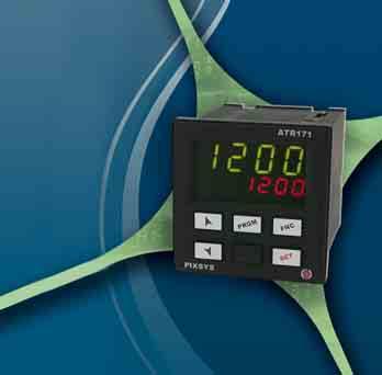

104 EN 104
ATR 401. Regolatore Controller Manuale Installatore User manual
 ATR 401 Regolatore Controller Manuale Installatore User manual Summary Page 1 Introduction 4 2 Model Identifi cation 4 3 Technical data 5 3.1 General data 5 3.2 Hardware data 5 3.3 Software data 6 4 Dimensions
The range of ATR243 controllers comes in three versions. Refer to the table below to easily select your preferred model.
 Summary 1 Introduction... 3 2 Model Identification... 3 3 Technical Data... 4 3.1 General Features... 4 3.2 Hardware Features... 4 3.3 Software Features... 5 4 Dimensions and Installation... 5 4.1 Panel
ISO-plus-RS4 ISO-plus-CAN
 ISO-plus-RS4 ISO-plus-CAN User manual Table of contents 1 Safety standards...5 2 Model identification...5 3 Technical data...5 3.1 Main features...5 3.2 Hardware Features...6 3.3 Software features...6
Controller URDR0001 User manual Version 1.0
 Controller URDR0001 User manual Version 1.0 Summary 1 Safety instructions...5 1.1 General instructions...5 1.2 Intended Usage...5 1.3 Qualified personnel...6 1.4 Remaining hazards...6 1.5 CE Conformity...6
DRR245. Controller - Regolatore. User manual - Manuale installatore
 DRR245 Controller - Regolatore User manual - Manuale installatore Index 1 Safety guide lines...5 2 Model identification...6 3 Technical Data...6 3.1 General data...6 3.2 Hardware data...6 3.3 Software
02/11/2015
 MIC48 With RS 485 link Part number 89422418 Heating and / or cooling function 2 independent alarms Load break detection 2 setpoint which can be selected remotely Manual / automatic power adjustment RS
02/11/2015
 CTH 46 - CTD 43 / 46 CTD 46 Part number 89422108 CTH 46 Heating / cooling function Measurement and setpoint display CTD 43 Heating or cooling function Measurement display Measurement deviation display-setpoint
Temperature Controllers
 Model TEC-4100 1/4 DIN Model TEC-4100 1/4 DIN Temperature Controller Ordering Code: Power Input BOX 1 4 = 90-250 VAC 5 = 11-26 VAC / VDC TEC-4100- Configurable for 4 Programmable Outputs and NEMA 4X/IP65
ATR244. Controller / Regolatore. User manual - Manuale installatore
 ATR244 Controller / Regolatore User manual - Manuale installatore Table of contents 1 Safety guide lines...6 2 Model Identification...7 3 Technical Data...7 3.1 General Features...7 3.2 Hardware Features...8
I/A Series 716C 1/16 DIN Temperature Controller
 Product Specifications I/A Series 716C 1/16 DIN Temperature Controller PSS 2C-1B5 A The Foxboro 716C is a powerful compact, 1/16 DIN, microprocessor-based temperature controller that offers a variety of
UR3274 Controller User manual. Version 1.0
 UR3274 Controller User manual Version 1.0 Summary 1 Safety instructions... 5 1.1 General instructions... 5 1.2 Intended Usage... 6 1.3 Qualified personnel... 6 1.4 Remaining hazards... 6 1.5 CE Conformity...
F4 Process Controller Installation and Operation Guide
 F4 Process Controller Installation and Operation Guide 1.Introduction 1.1.Highlight Features Space saving, only 55mm panel depth required Higher sampling rate (1mS) results in better control performance
Micro-controller X C C1 C2 AL1 AL2 AL3. Model: PXR4/5/9. Operation Manual SEL PXR. ECNO:406e
 C C1 C2 AL1 AL2 AL3 Micro-controller X Model: PXR4/5/9 PXR SEL Operation Manual ECNO:46e Table of Contents Part Names and Functions... 6 Operations... 7 2-1 Parameter list... 7 2-2 Basic operations...
ENERGY LIGHT USER S GUIDE ENERGY LIGHT USER S GUIDE
 ENERGY LIGHT USER S GUIDE Release January 2001 CONTENTS 1.0 GENERAL CHARACTERISTICS... 4 1.1 MAIN CHARACTERIS TICS... 4 2.0 USER INTERFACE (CODE C5121230)... 5 2.1 DISPLAY... 5 2.2 MEANING OF THE LEDS...
7EF/7HF/7EC/7ES Temperature Controllers
 7EF/7HF/7E/7ES Temperature ontrollers Dual 4 Digit LED Display Universal Input (6 T/, RTD, mv, V, ma) Autotuning NEMA 4X 100 to 240 Vac Switching Power Supply Algorithms for Heat or Heat/ool ontrol 2 Independent
VERTEX VT10 SERIES PID OPERATION MANUAL MICROPROCESSOR BASED PID CONTROLLER
 1 VERTEX VT10 SERIES PID OPERATION MANUAL MICROPROCESSOR BASED PID CONTROLLER 1. INTRODUCTION This manual contains information for the installation and operation and tuning of our Vertex VT10 series self-tuning
User manual FRONTAL IP65 1 UNIVERSAL ANALOGIC INPUT 2 RELAY OUTPUTS. 2 TRANSITOR OUTPUTS (PNP) SSR 1 ANALOGIC OUTPUT 0/10V, 4/20mA 2 DIGITAL INPUTS
 SSR 1 ANALOGIC OUTPUT 0/10V, 4/20mA 2 DIGITAL INPUTS") CONTROLLER DIS48-PLUS PROGRAMMING ALSO THROUGH SMARPHONE 1 UNIVERSAL ANALOGIC INPUT 0/10V, 4/20mA, Pt100, Thermocuple mv, ntc10k, PTC1K... 2 DIGITAL INPUTS 1 1 2 2 TIMERS FRONTAL IP65 POWER SUPPLY 24..
CONTROLLER DIS48-PLUS PROGRAMMING ALSO THROUGH SMARPHONE 1 UNIVERSAL ANALOGIC INPUT 0/10V, 4/20mA, Pt100, Thermocuple mv, ntc10k, PTC1K... 2 DIGITAL INPUTS 1 1 2 2 TIMERS FRONTAL IP65 POWER SUPPLY 24..
Nov 08 PRODUCT SPECIFICATION SHEET
 Honeywell UDC1200 and UDC1700 MICRO-PRO SERIES UNIVERSAL DIGITAL CONTROLLERS 51-52-03-35 Nov 08 PRODUCT SPECIFICATION SHEET OVERVIEW The UDC1200 & UDC1700 are microprocessor-based 1/16 DIN and 1/8 DIN
Tempco Part Number PCT30006 Temperature Control Enclosure with Relay Output for Tote Tank Heating Applications
 Instruction Manual Tempco Part Number PCT30006 Temperature Control Enclosure with Relay Output for Tote Tank Heating Applications Manual PCT30006, Revision 9/20/2016 The PCT30006 control enclosure incorporates
Series Temperature Controller Instruction Sheet
 Series Temperature Controller Instruction Sheet Thank you very much for purchasing DELTA A Series. Please read this instruction sheet before using your A series to ensure proper operation and please keep
UDC 700 Universal Digital Controllers and Indicator Specifications
 UDC 700 Universal Digital Controllers and Indicator Specifications 51-52-03-28 August 2002 Overview The UDC 700 is a 1/32 DIN (49 x 25 mm) controller which combines a high degree of technology and quality
UDC1000 and UDC1500 MICRO-PRO SERIES UNIVERSAL DIGITAL CONTROLLERS
 UDC1000 and UDC1500 MICRO-PRO SERIES UNIVERSAL DIGITAL CONTROLLERS EN0I-6041 4/01 PRODUCT SPECIFICATION SHEET OVERVIEW The UDC1000 and UDC1500 are microprocessor-based 1/16 DIN and 1/8 DIN controllers
Process & TeMPerATUre UniversAl input DigiTAl MeTers
 Process & TeMPerATUre UniversAl input DigiTAl MeTers nova PD56 series Thermocouple, rtd, & Process inputs Universal Power supply 1-24 va c Up to 3 Alarm relays retransmitting 4-2 ma output input Max/Min
Universal controller for panel mounting Models CS6S, CS6H, CS6L
 Accessories Universal controller for panel mounting Models CS6S, CS6H, CS6L WIKA data sheet AC 85.08 Applications Plant and industrial furnace construction Process engineering Plastics technology and processing
PROCESS & TEMPERATURE UNIVERSAL INPUT DIGITAL METERS
 PROCESS & TEMPERATURE UNIVERSAL INPUT DIGITAL METERS NOVA PD56 Series Thermocouple, RTD, & Process Inputs Universal Power Supply 1-24 VAC Up to 3 Alarm Relays Retransmitting 4-2 ma Output Input Max/Min
Tempco PCT-3000 Series Temperature Control Console with Relay Output for Heating or Cooling Applications
 Instruction Manual Tempco PCT-3000 Series Temperature Control Console with Relay Output for Heating or Cooling Applications Manual PCT-3000 Revision 9/2014 The PCT-3000 series control console incorporates
NOVUS AUTOMATION 1/5. Range: -35 to 720 C (-31 to 1328 F) Range: -90 to 1300 C (-130 to 2372 F) Range: 0 to 1760 C (-32 to 3200 F)
 Range: -90 to 1300 C (-130 to 2372 F) Range: 0 to 1760 C (-32 to 3200 F)") E N R S B Pt100 Pt100 Range: -35 to 720 C (-31 to 1328 F) Range: -90 to 1300 C (-130 to 2372 F) Range: 0 to 1760 C (-32 to 3200 F) Range: 0 to 1760 C (-32 to 3200 F) Range: 150 to 1820 C (302 to 3308 F)
E N R S B Pt100 Pt100 Range: -35 to 720 C (-31 to 1328 F) Range: -90 to 1300 C (-130 to 2372 F) Range: 0 to 1760 C (-32 to 3200 F) Range: 0 to 1760 C (-32 to 3200 F) Range: 150 to 1820 C (302 to 3308 F)
UR3274Sx and UR3274Ax Controller User manual. Version 1.0
 and Controller User manual Version 1.0 Summary 1 Safety instructions... 5 1.1 General instructions... 5 1.2 Intended Usage... 6 1.3 Qualified personnel... 6 1.4 Remaining hazards... 6 1.5 CE Conformity...
Table of Contents SECTION PAGE
 Table of Contents SECTION PAGE SECTION 1 INTRODUCTION................... 1.1 Description.............................. 1.2 Features................................ 1.3 Models.................................
OVEN INDUSTRIES, INC.
 OVEN INDUSTRIES, INC. OPERATING MANUAL Model 5C7-252 TEMPERATURE CONTROLLER With PLC Inputs Introduction Thank you for purchasing our controller. The Model 5C7-252 is an exceptionally versatile unit and
SA100. General Description. Features. Temperature Controller SA100. Corresponding to Various Applications. Simple Mounting on DIN Rail
 Temperature Controller General Description The is a socket mounting type temperature controller and is available for mounting inside the panel or by easily mounting on DI rail. The has features such as
TEMPERATURE CONTROL MODULE MODEL R3-TC2
 INSTRUCTION MANUAL R3-TC2 TEMPERATURE CONTROL MODULE MODEL R3-TC2 CONTENTS BEFORE USE... 2 POINTS OF CAUTION... 2 COMPONENT IDENTIFICATION... 2 INSTALLATION... 2 EXTERNAL DIMENSIONS unit: mm (inch)...
CTT8 TEMPERATURE MONITOR DEVICE
 INSTRUCTION MANUAL IM302-U v2.3 CTT8 TEMPERATURE MONITOR DEVICE GENERALITY The device of control temperatures CTT8 is used in the control of electric machine, transformer, motor, etc. where it s possible
Installation Manual Tracker 221
 Installation Manual Tracker 221 KSR KUEBLER AG Im Kohlstatterfeld 17 D-69439 Zwingenberg / Germany www.ksr-kuebler.com Contents About this Installation Manual...4 Description Tracker 220-series...4 Installing
Carbon Monoxide Transmitter
 Introduction The CO Transmitter uses an electrochemical sensor to monitor the carbon monoxide level and outputs a field-selectable 4-20 ma or voltage signal. The voltage signal may also be set to 0-5 or
TECHNICAL MANUAL CVM 3000 C 5030 CV/04-99 GB
 Summary 1 CONNECTIONS... 8 1.1 TEMPERATURE PROBES...8 1.2 PRESSURE PROBES...9 1.3 LOW VOLTAGE DIGITAL INPUTS...10 1.4 LIVE DIGITAL INPUTS...11 1.5 RELAY OUTPUTS...12 2 VOLTAGE/FREQUENCY INPUT...13 3 POWER
MO n : 12JMC rév A
 CTT8 MO n : rév A Page 2 / 18 MODIFICATIONS Rev. Description Date Checked by Approuved by Z Creation 2012/02/12 JMC LA A First issue 2012/02/14 JMC LA INDEX Page 3 / 18 GENERALITY 4 INTRODUCTION 4 ACCESSORIES
ST710-KHJV.03. Wiring diagram. Product description. Temperature controller. Order number
 ST71-KHJV.3 Temperature controller Order number 921.8 Wiring diagram Product description The switching outputs of the thermal controller can be programmed as -two-point controller with alarm -three-point
CONsOlIDATOR 4 & 8. MulTI- C h ANNEl CONTROllERs. ConsoliDator 4 Model PD940 ConsoliDator 4 Features. ConsoliDator 8 Features.
 CONsOlIDATOR 4 & 8 MulTI- C h ANNEl CONTROllERs ConsoliDator 4 Model PD940 ConsoliDator 4 Features Four 4-20 Four 4-20 Outputs ConsoliDator 8 Features Eight 4-20 Two 4-20 Outputs Common Features Four Pulse
Communications None RS-232C RS-422* RS-485* BCD Transmission output*/** (4 to 20 ma) E5AX- E5AX- L(M)A02 L(M)A03
 E5AX- E5AX- L(M)A02 L(M)A03") Digital Controller A 96 x 96-mm (DIN) Digital Process Controller Optimum PID control with feed-forward control circuitry. High accuracy (+0.3% FS +1 digit max.). Replaceable Output Units. Models with communications
Digital Controller A 96 x 96-mm (DIN) Digital Process Controller Optimum PID control with feed-forward control circuitry. High accuracy (+0.3% FS +1 digit max.). Replaceable Output Units. Models with communications
INSTRUCTION MANUAL FOR MICROCOMPUTER BASED TEMPERATURE INDICATING CONTROLLER FCS-23A
 INSTRUCTION MANUAL FOR MICROCOMPUTER BASED TEMPERATURE INDICATING CONTROLLER Thank you for your purchase of our Microcomputer based Temperature Indicating Controller. This manual contains instructions
TEMON 4-C. Doc. N MO-0368-ING TEMPERATURE MONITOR DEVICE TYPE TEMON 4-C OPERATION MANUAL. Microener- Copyright 2010 FW 2.1 Date Rev.
 TEMPERATURE MONITOR DEVICE TYPE TEMON 4-C OPERATION MANUAL Microener- Copyright 2010 FW 2.1 Date 01.12.2008 Rev. 0 1. Generality 3 2. Introduction 3 3. Accessories and Options 3 4. Installation 3 5. Connection
DIMENS. MIN TYPICAL MAX A 71.0 (2.795) 71.0 (2.795) 71.8 (2.826) B 29.0 (1.141) 29.0 (1.141) 29.8 (1.173)
 71.0 (2.795) 71.8 (2.826) B 29.0 (1.141) 29.0 (1.141) 29.8 (1.173)") Evco S.p.A. Code 104K204E05 page 1/5 EVK204 Digital controller for ventilated refrigerating units, with HACCP and Energy Saving functions version 1.05 GB ENGLISH 1 PREPARATIONS 1.1 Important Please read
Evco S.p.A. Code 104K204E05 page 1/5 EVK204 Digital controller for ventilated refrigerating units, with HACCP and Energy Saving functions version 1.05 GB ENGLISH 1 PREPARATIONS 1.1 Important Please read
TECHNICAL MANUAL CVM 20 C 5005 CV/04-99 GB
 Summary 1 CONNECTIONS... 3 1.1 TEMPERATURE PROBES...3 1.2 LOW VOLTAGE DIGITAL INPUTS...3 1.3 LIVE DIGITAL INPUTS...4 1.4 RELAY OUTPUTS...5 2 POWER SUPPLY... 6 3 SERIAL CONNECTIONS... 6 4 SOFTWARE... 7
MF-PFA ver 3.x. Micaflex PFA ver 3. Pressure- and Flow transmitter with alarmfunction. Installation- & Operation manual [Dok. id: mi-303gb_180528]
![MF-PFA ver 3.x. Micaflex PFA ver 3. Pressure- and Flow transmitter with alarmfunction. Installation- & Operation manual [Dok. id: mi-303gb_180528]](/thumbs/95/126098054.jpg "MF-PFA ver 3.x. Micaflex PFA ver 3. Pressure- and Flow transmitter with alarmfunction. Installation- & Operation manual [Dok. id: mi-303gb_180528]") Installation- & Operation manual [Dok. id: mi-303gb_180528] Micaflex PFA ver 3. Pressure- and Flow transmitter with alarmfunction and control output MF-PFA ver 3.x NOTE! Read through the entire manual
Installation- & Operation manual [Dok. id: mi-303gb_180528] Micaflex PFA ver 3. Pressure- and Flow transmitter with alarmfunction and control output MF-PFA ver 3.x NOTE! Read through the entire manual
User s Guide CN616A. Universal 6 Channel ¼ DIN Process Controller. Shop online at omega.com
 TM User s Guide Shop online at omega.com e-mail: info@omega.com For latest product manuals: www.omegamanual.info CN616A Universal 6 Channel ¼ DIN Process Controller omega.com info@omega.com U.S.A. Headquarters:
TC515 and TC600 Installation Manual. a Winters company
 THERMOLINE TEMPERATURE CONTROLLERS TC515 and TC600 Installation Manual a Winters company Guarantee 12 months Congratulations on the purchase of this new product. Special care with the design, workmanship
Refrigerated air dryers
 Refrigerated air dryers OPERATING AND MAINTENANCE MANUAL Original instructions 38178800319 OPERATING AND MAINTENANCE MANUAL - Contents 1 CONTENTS CONTENTS... 1 Chapter 1 IDRY ELECTRONIC CONTROLLER...
DPR-145 TEMPERATURE PROTECTION RELAY. DPR-145 User Manual V-2.0 ( ) PT100 INPUTS: 4 RELAY OUTPUTS: 4 RS-485 MODBUS PORT VDC SUPPLY -1-
 PT100 INPUTS: 4 RELAY OUTPUTS: 4 RS-485 MODBUS PORT VDC SUPPLY -1-") DPR-45 User Manual V-2.0 (2..206) DPR-45 TEMPERATURE PROTECTION RELAY PT00 INPUTS: 4 RELAY OUTPUTS: 4 RS-485 MODBUS PORT 9-50VDC SUPPLY DESCRIPTION DPR-45 is a precision unit designed for the temperature
DPR-45 User Manual V-2.0 (2..206) DPR-45 TEMPERATURE PROTECTION RELAY PT00 INPUTS: 4 RELAY OUTPUTS: 4 RS-485 MODBUS PORT 9-50VDC SUPPLY DESCRIPTION DPR-45 is a precision unit designed for the temperature
Important Supplementary Manual to the main Ezeio manual. 5. Section 2a: Introducing the 2400 input and output expansion field stations.
 1 P age Ezeio v9-120317 Eze Cloud Based Monitoring Systems. Created by Intech Instruments Ltd December 2014 Important Supplementary Manual to the main Ezeio manual. Ezeio Controller and the 2400-A16 input
Specification , July 2015
 Technical Information PrecisionLine Controllers EDC21 / EDC22 / EDC23 EASYSET DIGITAL CONTROLLERS Specification 51-52-3-48, July 215 Introduction The EDC21, EDC22 and EDC23 controllers provide precise
VERTEX F4 Instruction Manual
 VERTEX F4 Instruction Manual 02/2018 The VERTEX F4 controller 1/16 DIN is our LOW COST yet HIGH SPEC controller. Configurable on input between various thermocouples from the keypad by the user or when
ModSync Sequencing System Installation & Operation Manual. For use with Fulton Steam Boilers.
 ModSync Sequencing System Installation & Operation Manual For use with Fulton Steam Boilers. Revision 3.0 8/21/2008 - 2 - Table of Contents Introduction Page 4 Features Page 4 Sequence of Operation Page
SA200. General Description. Features. Temperature Controller SA200. Self-Tuning Algorithm. Close Vertical or Horizontal Mounting
 Temperature Controller General Description The is a high performance 3 nd DI controller that has been specifically designed for applications where panel space is critical. Though small in size, this controller
CDR-AL Room CO 2 Traffic Light Alarm Units and Sensors
 Product sheet SN1.402 Type CDR-AL CDR-AL Room CO 2 Traffic Light Alarm Units and Sensors CDR-AL sensors are designed to detect carbon dioxide concentration and temperature in the room spaces. The units
Product Manual SZ1145
 Product Manual SZ114 General Purpose Monitor Communicating Controls Description The SZ114 is a microprocessor-based monitoring and alarm interface designed to monitor up to four 1000 Ω platinum temperature
INSTRUCTION MANUAL FOR MICROCOMPUTER BASED TEMPERATURE INDICATING CONTROLLER JCD-13A, JCR-13A
 INSTRUCTION MANUAL FOR MICROCOMPUTER BASED TEMPERATURE INDICATING CONTROLLER JCD-13A, JCR-13A Preface Thank you for the purchase of our Microcomputer based Temperature Indicating Controllers JCD-13A or
Serie Rugghölzli 2 CH Busslingen. Tel. +41 (0) Fax +41 (0)
 Fax +41 (0)") Serie 5000 Tel. +1 (0)5 222 Fax +1 (0)5 222 12 PRODUCT INTRODUCTI PRODUCT INTRODUCTI 5 Series programmable temperature controller is FineTek's mid-range series of controllers. It uses a 12bit analog /
Serie 5000 Tel. +1 (0)5 222 Fax +1 (0)5 222 12 PRODUCT INTRODUCTI PRODUCT INTRODUCTI 5 Series programmable temperature controller is FineTek's mid-range series of controllers. It uses a 12bit analog /
ABB Instrumentation. Specifications. COMMANDER 150 Universal Process Indicator. the 1 /8 DIN indicator to match all your display requirements
 Specifications COMMANDER 150 Universal Process Indicator High visibility 6-digit LED display the clearest view of your process status 0.1% measurement accuracy precise indication of process measurement
eed quality electronic design USER s MANUAL
 eed quality electronic design www.dem-it.com eed www.qeed.it info@qeed.it ANALOG SIGNAL DISPLAY Q-DISP-T USER s MANUAL The displays Q-DISP-T, prepared for mounting on the back panel, 96x48mm, will allow
Product Manual SZ1144
 Product Manual SZ1144 Refrigeration Temperature Monitor Communicating Controls Description The SZ1144 is a microprocessor-based monitoring and alarm interface designed to monitor up to four 1000 Ω platinum
TDF 15 MICROPROCESSOR-BASED DIGITAL ELECTRONIC THERMOCONTROLLER. OPERATING INSTRUCTIONS Vr. 01 (ENG) - cod.: ISTR TECNOLOGIC S.p.A.
 - cod.: ISTR TECNOLOGIC S.p.A.") TDF 15 MICROPROCESSOR-BASED DIGITAL ELECTRONIC THERMOCONTROLLER INDEX 1 1.1 1.2 2 2.1 2.2 3 3.1 3.2 3.3 3.4 4 4.1 4.2 4.3 4.4 4.5 4.6 5 5.1 5.2 6 6.1 6.2 6.3 7 7.1 7.2 7.3 7.4 7.5 INSTRUMENT DESCRIPTION
TDF 15 MICROPROCESSOR-BASED DIGITAL ELECTRONIC THERMOCONTROLLER INDEX 1 1.1 1.2 2 2.1 2.2 3 3.1 3.2 3.3 3.4 4 4.1 4.2 4.3 4.4 4.5 4.6 5 5.1 5.2 6 6.1 6.2 6.3 7 7.1 7.2 7.3 7.4 7.5 INSTRUMENT DESCRIPTION
INSTRUCTION MANUAL Micro-computer based digital indicating controller
 INSTRUCTI MANUAL Micro-computer based digital indicating controller TP4A To prevent accidents arising from the misuse of this controller, please ensure the operator using it receives this manual. Caution
Microprocessor-based digital electronic controller TLK 38
 1. General description is a single loop digital microprocessor-based controller, with ON/OFF, Neutral Zone ON/ OFF, PID single action, PID dual action (direct and reverse) control and with AUTO-TUNING
Module Features are-configurable, no module jumpers to set
 December 2011 PACSystems* RX3i Isolated Thermocouple Input Module, 6 Channels, IC695ALG306 Isolated Thermocouple Input Module, 12 Channels, IC695ALG312 Isolated Thermocouple Input module IC695ALG306 provides
ENERGY 200 Electronic Control for mono & bi- Compressor CHILLERS. User Manual
 Electronic Control for mono & bi- Compressor CHILLERS User Manual 2/55 1 CONTENTS 1 Contents...3 2 How to use this manual...5 3 Introduction...6 3.1 Components...6 3.1.1 Basic module...6 3.1.2 Keyboards...6
Q-SMART MODBUS KIT. Modbus Protocol & Parameters. Cod EN rev.a ed.08/2018. Q-SMART Software Version AE17
 Q-SMART MODBUS KIT Modbus Protocol & Parameters Cod.001085120EN rev.a ed.08/2018 Q-SMART Software Version AE17 Index 1 Modbus Protocol on Q-SMART... 4 1.1 Broadcasting... 4 1.2 Data Protection... 4 1.3
VT4810 SINGLE / DUAL ZONE CONTROLLER INSTALLATION MANUAL
 Thermocouple Type BS4937 (IEC584-3): Outer / + / - BS1843 (Old UK Standard) Outer / + / - US Outer / + / - J : Iron / Copper-Nickel Black / Black / White Black / Yellow / Blue Black / White / Red VT4810
Digi-Sense TC9000 Advanced PID and On/Off Temperature Controller with Thermocouple Input
 User Manual 99 Washington Street Melrose, MA 02176 Phone 781-665-1400 Toll Free 1-800-517-8431 Visit us at www.testequipmentdepot.com Digi-Sense TC9000 Advanced PID and On/Off Temperature Controller with
Warning Caution INSTRUCTION MANUAL DIN RAIL MOUNTING TYPE INDICATING CONTROLLER
 INSTRUCTI MANUAL DIN RAIL MOUNTING TYPE INDICATING CTROLLER 1 DCL-A DC No.DCLDCE1 2007.01 Thank you for purchasing our DIN rail mounting type indicating controller DCL-A DC. This manual contains instructions
General Specifications
 General Specifications GS J0H-0E Model MVHK Digital Limit Alarm (DC Type) with Active Color PV Display General This plug-in type Digital Limit Alarm for DC input receives DC current or DC voltage signal.
User Manual. Digi-Sense TC9500 Advanced Multiparameter Temperature Controller with Thermocouple, Thermistor, and RTD Inputs
 User Manual Digi-Sense TC9500 Advanced Multiparameter Temperature Controller with Thermocouple, Thermistor, and RTD Inputs Models 89800-03 and 89800-04 THE STANDARD IN PRECISION MEASUREMENT Table of Contents
Installer Manual KNX Touchscreen Thermostat
 Installer Manual 02952 KNX Touchscreen Thermostat Index GENERAL FEATURES AND FUNCTIONALITY from page 5 ETS PARAMETERS AND COMMUNICATION OBJECTS from page 7 COMMUNICATION OBJECTS GENERAL FEATURES AND FUNCTIONALITY
DC VOLTMETER DCV-10 / 10A / 10C / 10S / 10CS / 11 / 11A / 11C / 11S / 11CS. A4741 / Rev.1
 DC VOLTMETER DCV-10 / 10A / 10C / 10S / 10CS / 11 / 11A / 11C / 11S / 11CS User Manual and Menu Map A4741 / Rev.1 www.entes.com.tr ATTENTION -Disconnect all power before connecting the device. -Don t remove
EasyTronic III MANUAL SERVICE
 rev.6 EasyTronic III MANUAL SERVICE General characteristics: Power supply 24 Vac ±15% Max consumption at 24Vac 300mA Relay outputs 6 Maximum relay current 8 A res. Serial standard RS232 2 Serial standard
PACSystems* RX3i. Thermocouple Input Module, 12 Channels, IC695ALG412. GFK-2578B October 2011
 October 2011 PACSystems* RX3i Thermocouple Input Module, 12 Channels, IC695ALG412 The PACSystems * Thermocouple Input module IC695ALG412 provides twelve isolated differential thermocouple input channels.
Mark 25 Ultrapure Water Conductivity Analyzer
 Martek Instruments, Inc. Mark 25 Ultrapure Water Conductivity Analyzer Instruction Manual WARRANTY POLICY Unless otherwise stated, MARTEK INSTRUMENTS, INC. warrants this equipment to be free from defects
Modular Standard HP Chiller 1/4 screw compressor with Carel driver
 Program for pco¹ pco 2 and pcoc Modular Standard HP Chiller 1/4 screw compressor with Carel driver Manual version 1.0 25 September 2003 Program code: FLSTDmMSDE Do we want you to save you time and money?
Instruction manual Micro-computer based digital indicating controller
 Instruction manual Micro-computer based digital indicating controller JCS-33A To prevent accidents arising from the misuse of this controller, please ensure the operator using it receives this manual.
ST Wiring diagram. Product description. Four-stage controller. Order number
 ST96-35.16 Four-stage controller Order number 99.2 Wiring diagram Product description The four-stage controller with 4-digit setpoint and actual value display, 3 keys and 4 relays was developed for the
Instruction manual Temperature Controller KT7
 Instruction manual Temperature Controller KT7 No. KT71E7 201.05 To prevent accidents arising from the misuse of this controller, please ensure the operator receives this manual. SAFETY PRECAUTIS Be sure
Series Digital Controller Instruction Sheet
 216/3/11 Series Digital Controller Instruction Sheet Thank you very much for purchasing DELTA DTC Series Temperature Controller. Please read this instruction sheet before using your DTC series to ensure
Communications* None RS-232C RS-422 RS-485 BCD Transmission output** (4 to 20 ma)
") TEMPERATURE CONTROLLER DIN-sized (96 x 96-mm) Temperature Controller Featuring Advanced PID Control and Heater Burnout Detection Advanced PID control with two degrees of freedom to improve stability and
TEMPERATURE CONTROLLER DIN-sized (96 x 96-mm) Temperature Controller Featuring Advanced PID Control and Heater Burnout Detection Advanced PID control with two degrees of freedom to improve stability and
Model 96VTR ¼ DIN Process Controller
 99 Washington Street Melrose, MA 02176 Phone 781-665-1400 Toll Free 1-800-517-8431 Visit us at www.testequipmentdepot.com Back to the Extech 96VTR Product Info Page INSTRUCTION MANUAL Model 96VTR ¼ DIN
User Manual. Dryer Controller M720
 User Manual Dryer Controller M720 Hardware version 1.00 Software version 1.00 Preliminary version Manual M720 Dryer controller Page 1 of 42 Document history Preliminary version: - Created in April, 2009
<IMG INFO> 339,95 195, ,35 14,15-1. ENERGY 400 Four Steps Chiller Heat Pump Controller
 339,95 195,85 0 2 89,35 14,15-1 Four Steps Chiller Heat Pump Controller 1 CONTENTS 1 Contents...2 2 How to use this manual...4 3 Introduction...5 3.1 Components...5 3.1.1 Basic Module...5 3.1.2
Nokeval. No Manual. Model 2026 Totalizer / Batch controller for analog inputs
 No 00 Nokeval Manual Model 0 Totalizer / Batch controller for analog inputs Contents Rate / Batch controller 0 for analog inputs... Dimensions... Front panel indicators and buttons... Configuration...
UDC100 Universal Digital Controller Specifications
 UDC100 Universal Digital Controller Specifications 51-52-03-29 November 1999 Overview The UDC100 Universal Digital Controller is a microprocessor-based 1/4 DIN low cost temperature controller. It combines
TLK39 MICROPROCESSOR-BASED DIGITAL ELECTRONIC CONTROLLER. OPERATING INSTRUCTIONS Vr (ENG) - cod.: ISTR 06262
 - cod.: ISTR 06262") TLK39 MICROPROCESSOR-BASED DIGITAL ELECTRONIC CONTROLLER OPERATING INSTRUCTIONS Vr. 02.1 (ENG) - cod.: ISTR 06262 FOREWORD: This manual contains the information necessary for the product to be installed
TLK39 MICROPROCESSOR-BASED DIGITAL ELECTRONIC CONTROLLER OPERATING INSTRUCTIONS Vr. 02.1 (ENG) - cod.: ISTR 06262 FOREWORD: This manual contains the information necessary for the product to be installed
CELLTROL II BIOREACTOR CONTROL SYSTEM OPERATIONS MANUAL
 Operation Manual Celltrol II Bioreactor Control System Page 1 of 33 Table of Contents 1) Introduction... 3 1.1) Scope of Document... 3 1.2) Control System Overview... 3 1.3) Introduction to Celltrol II...
XC1008D -XC1011D- XC1015D and VGC810
 Electronic Controller for Compressor Racks XC1008D -XC1011D- XC1015D and VGC810 Instructions Manual INDEX 1. GENERAL WARNING 4 1.1 PLEASE READ BEFORE USING THIS MANUAL 4 1.2 SAFETY PRECAUTIONS 4 2. WIRING
K38 CONTROLLER AND MINI-PROGRAMMER. Engineering Manual General notes about wiring. 1.1 Dimensions. 2.2 Inputs. 1.2 Mounting requirements
 K38 2. CNECTI DIAGRAM RELAY: 8A-AC1 (3A-AC3)/250VAC SSR: 8mA/8VDC CTROLLER AND MINI-PROGRAMMER Power supply C NC NO C NC NO INPUT OUT1 OUT2 Pt100 PTC-NTC Out 12 VDC max. 20 ma TC/mV 4... 20 ma passive
R1000 / R1040 / R1080
 R1000 / R1040 / R1080 1 Zone Temperature Controller: Heat-only Heating-off-cooling Three-point stepping DIN-Format: 96mm x 96mm / 48mm x 96mm / 96mm x 48mm Description and operating manual ELOTECH Industrieelektronik
CONTROLS MANUAL. CARRIERrtc basic & medium electronic control 48/50 EN/EH 50 HB/HF/NZ/NF. Original document
 CONTROLS MANUAL CARRIERrtc basic & medium electronic control 48/50 EN/EH 50 HB/HF/NZ/NF Original document Contents 1. General description....5 2. Set-up... 6 2.1. micropc control board... 6 2.2. TCO user
DT968C C.T. BATH CONTROLLER
 DT968C C.T. BATH CONTROLLER MANUAL (DT968C, 9-5-01) ICD/HEATEFLEX Page 1 DT968C CONSTANT TEMPERATURE BATH CONTROLLER The Model DT968C is a microprocessor based controller/timer. It monitors temperature
Dryer Controller M720
 User Manual Dryer Controller M720 Hardware version 2.00 Software version 2.00 Manual M720 Dryer controller Page 1 of 60 Document history Preliminary version: - Created in April, 2009 Hardware Version 2.00,
User s Guide. CN616 Series 1 4 DIN Economical 6-Zone PID Temperature Controllers. Shop online at omega.com SM
 User s Guide Shop online at omega.com SM e-mail: info@omega.com For latest product manuals: www.omegamanual.info CN616 Series 1 4 DIN Economical 6-Zone PID Temperature Controllers omega.com info@omega.com
EasyTech.Full Temperature Controller for Pellet Stove. Idro
 EasyTech.Full Temperature Controller for Pellet Stove EasyTech.One is a Pellet stoves control system available in Air and Hydro version. Is characterised by: Installing and use simplicity Simple and direct
A36D/TPSD Modbus RTU (Serial) SCADA INTERFACE INSTRUCTIONS
 SCADA INTERFACE INSTRUCTIONS") SCADA INTERFACE INSTRUCTIONS - OPTION 21S - FOR A36D/TPSD SYSTEMS with option 500 and 550. A36D/TPSD Modbus RTU (Serial) SCADA INTERFACE OPTION 21S INSTRUCTIONS This manual is valid for A36D/TPSD Chargers
SCADA INTERFACE INSTRUCTIONS - OPTION 21S - FOR A36D/TPSD SYSTEMS with option 500 and 550. A36D/TPSD Modbus RTU (Serial) SCADA INTERFACE OPTION 21S INSTRUCTIONS This manual is valid for A36D/TPSD Chargers
VTI MODEL itc5000 HEAT TRACING CONTROL SYSTEM OPERATIONS MANUAL
 VTI MODEL itc5000 HEAT TRACING CONTROL SYSTEM OPERATIONS MANUAL 1 Operations Manual for the VTI Model itc5000 Heat Tracing Control System Description The VTI Model itc5000 Heat Tracing Control System consists