Assembly Instruction GfS Door Terminal
|
|
|
- Zoe Watts
- 5 years ago
- Views:
Transcription


1 Part No.: Assembly Instruction GfS Door Terminal Part No.: Safety on doors
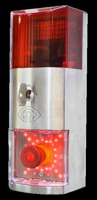
2 GfS Door Teminal Part No.: INDROTUCTION/SAFETY INSTRUCTION INSTALLATION The GfS Door Terminal is a compact device to steer up to 2 holding magnets which are mounted on emergency exit doors. It includes emergency exit switch, flash light, buzzer and key switch. The housing is made out of solid stainless steel. In order to make full use of all GfS Door Terminal features and to assure the safety of the operator it is important to act according to the following instructions. Before connecting and operating the device please read the operating manual carefully. The eletric installation must be executed by an authorized installer Before opening the device the external power supply has to be switched-off In case of system failure please disconect the device and ask an authorized installer to repair it Please use the device just according to the following instruction IMPORTANT: Connect the GfS Door Terminal completely before applying voltage. Mount the GfS Door Terminal on the wall with the enclosed screws (see hole pattern). You can find the different measures on page 4) Connect all required cables Tighten the screws of the emergency exit button insertion (positioned horizontally) Tighten the screws of the cover of the LED-field (positioned vertically) Now, apply the voltage Carry out function test ATTENTION GfS recommends to checks the functions of the GfS Door Terminal every 6 months. This assembly instruction should be handed on to the operator Weitergabe oder Vervielfältigung dieser Bedienungsanleitung, Verwertung und Mitteilung ihres Inhalts sind nicht gestattet, soweit nicht ausdrücklich zugestanden. Zuwiderhandlungen verpflichten zu Schadenersatz. Alle Rechte für den Fall der Patenterteilung oder Gebrauchsmuster- Eintragung vorbehalten. Die Angaben in dieser Bedienungsanleitung können ohne vorherige Ankündigung geändert werden. Die Zusammenstellung der Informationen in dieser Bedienungsanleitung erfolgt nach bestem Wissen und Gewissen. GfS Gesellschaft für Sicherheitstechnik mbh übernimmt keine Gewährleistung für die Richtigkeit und Vollständigkeit der gemachten Angaben. Insbesondere kann GfS Gesellschaft für Sicherheitstechnik mbh nicht für Folgeschäden aufgrund fehlerhafter oder unvollständiger Angaben haftbar gemacht werden. Da sich Fehler, bei aller Sorgfalt nie vermeiden lassen, sind wir für Hinweise jederzeit dankbar. Escape direction 2
3 Part No.: GfS Door Teminal TECHNICAL DATA Power supply 12V-24V DC Consumption State of activation 365 ma (1 holding magnet) State of alarm 150 ma Degree of protection IP 20 Output 1 incident message relay Max. contact load DC 30V/0,5A Operating temperature -20C bis +60C Dimensions 90 x 240 x 80 mm Weight ca. 1,6 kg 2x 32 LED (red/) for displaying the actual status integrated buzzer with 100dB/ 1m integrated flash light emergency exit switch acc. to EN integrated key switch 2 mm thick, robust stainless steel housing integrated control unit reusable cover for emergency exit switch made out of Macrolon Input 12-24V/DC supply single remote opening permanent remote opening 2x holding magnet signals door-too-long-open alarm intrusion-alarm (or bridge), clamps briged = door closed 2x sabotage alarm 2x predefined brightnesses of LED fire alarm control system (with bridge normal operation) emergency exit switch with internal fail safe contacts reserve input Output 2x holding magnet (electric escape route strikes) RS-485 interface (bi-directional, half duplex) for integration into building control systems external sirène 24V, 0,5A OC external flash light 24V, 0,5A OC incident message relay (collective message) 30 V, 0,5 A Conformity This product complies with the essential requirements of the R&TTE guideline 1999/5/EG. The certificate of conformity you may request from your supplier. Disposal Dispose an obselet GfS Door Terminal at a a colleting point for electronic waste or at your supplier. Dispose the packaging material at a paper collecting point for paper resp. plastic. You may not dispose an obsolte device the general garbage. Warrenty Within the legal warrenty time we intend to repair all defect devices, whether the defect is caused by the material or assembly, or replace them. The warenty expires after a third-party repair. Service In case of a system failure or a defect GfS Door Terminal please contact the following address: 3
4 GfS Door Teminal Part No.: DIMENSION
5 Part No.: GfS Door Teminal TERMINAL DIAGRAM + 12 V 24 V GND + 24 V FACS FACS Dim Res 1 GND ext. sir. ext. flash NO 1 NO 2 GND Mag Mag + GND REM GND DC RS485-A RS485-B DST COM NC NO Pos Abb. Function Signal 1 GND Operating voltage minus Ground 2 +24V Operating voltage plus +24 V 3 FACS Fire alarm control system Floating contact or bridge to 4 4 FACS Fire alarm control system Floating contact or bridge to 3 5 NO1 Response magnet 1 Ground is switched, holding magnet 1 is energized (Hall Relay NO) 6 NO2 Response magnet 2 Ground is switched, holding magnet 2 is energized (Hall Relay NO). In case that there is just 1 magnet, 6 and 7 must be bridged! 7 GND Common GND Magnets GND-Signal (Hall Relais COM) 8 Magnet- Magnet- Coil 1 and 2 Negative connection for magnets 9 Magnet + Magnet+ Coil 1 and 2 Positive connection for magnets 10 GND Reference for remote opening Signal ground 11 REM Remote opening input Switch-on GND resp. bridge 10 and 11 Opening command 12 GND Reference contact for door contact Signal GND 13 DC Contact Switch-on GND resp. bridge 12 and 13. Door closed 14 RS-485A Communication Data signals 15 RS-485B Communication Data signals 16 DST Communication multi function port Acc. to the required functions as input or output, also usable for communication purposes with 1 wire 17 COM Incident message relay COM Floating contact 30 V/0,5 A max 18 NC Incident message relay NC Floating contact 30 V/0,5 A max 19 NO Incident message relay Floating contact 30 V/0,5 A max 20 ext. flash External flash light Open collector-output, 30V/ 0,5A max 21 ext. sir. External siren Open collector-output, 30V/ 0,5A max 22 GND Reference for reserve and dim input Signal GND 23 Res1 Reserve input Free function 24 Dim Dim input Switch-on GND resp. bridge 24 with 22. Dim command 5
6 GfS Door Teminal Part No.: FUNCTIONS Alarm secured LED ring with cross shines red Incident message relay is activated, emergency exit switch is illuminated, magnet is activated, door contact closed (DC connected) as well as magnet 1 and 2. red Opening time delay At the end of the opening time delay (5 sec. preset, adjustable) the LEDs blink slowly twice and the GfS Door Terminal is activated again. Precondition: Holding magnet and door contact are closed. When the door is opened during the opening time delay and no opening contact active, the status changes directly into Waiting for door too be closed Opening command 1 Turn key switch to the right. LED ring with corners blink. Magnet is deactivated, the door may be opened once without causing an alarm. Opening command 2 Input Remote activated. Opening command remains active as long as the GfS Door Terminal receives the signal plus opening time delay. 6
7 Part No.: GfS Door Teminal FUNCTIONS Permanent opening Permanent opening is active as long as Input Remote is activated. Permanent opening with key switch: Turn key switch clockwise for at least 5 sec., till LEDs expire. Remove key. LEDs and emergency exit switch illumination are pulsing. Door may be opened as long and as often as desired. Magnets are permanently deactivated. pulse Waiting for door to be closed The LEDs blink slowly at the end of the opening time. In case that the holding magnet and door contact are not closed the LEDs blink for another 15 sec (till conditions for activation are met). blinks slowly Door-too-long-open If the door stays open for more than 15 sec. an alarm Door-too-long-open is triggered. Every 3 secs the LEDs change for 200 ms into red, while the internal and external buzzers are activated. Deactivation of alarm Close door (door reed contact, counter plate) or give again an opening command (opening command 1 and 2 possible) Intermitting red/ LEDs + buzzer Emergency exit switch alarm Push emergency exit switch Flash-light, buzzer (internal and external) are activated, deactivation of incident message relay, magnets are seperated and deactivated by the processor. LEDs blink quickly (as after opening command). Reset of alarm just possible with key switch. Unlatch emergency exit switch. blinks + siren + flash light 7
8 GfS Door Teminal Part No.: FUNCTIONS Intrusion, sabotage In case that one of the two feedback loops of the holding magnets or door contacts are interrupted, an intrusion alarm is triggered. LEDs change from red to orange. The incident message relay is deactivated, the external siren is activated. The magnet stays active! Reset just possible with key switch (turn right). In case that the PCB is removed (sabotage on the GfS Door Terminal) he same alarm is triggered. orange + siren Fire alarm In case of a central fire alarm clamp 3 and 4 are seperated, the failure relay is deactivated. Holding magnets are seperated and deactivated by the processor. LEDs blink quickly (like open). The emergency exit switch illumination blinks in push-pull. The deactivation of the alarm only with key switch (turn right) possible. blinks 8
9 Part No.: GfS Door Teminal PROGRAMMING Programming 1 Turn key switch to the right (create status open) 2 Hold key switch left at least for 5 sec. till orange ring shines 3 Turn key switch to the left, release 4 Turn briefly key switch to the left. Repeat this in order to enter other programming modes 5 Turn key switch to the right in order to confirm the correct programming mode 6 Turn key switch to the right in order to change the status/ value 7 Turn key switch to the left in order to store the value and finish programming mode Programming mode 1 Open time delay 2 Silent alarm 3 Accoustic alarm switch-off orange orange orange Change opening time Execute programming steps 1-3 Orange LED ring shines. Programming mode: opening time. Start programming execute step 5 (turn to the right) (Confirm programming mode by turning key to the left) Orange LED ring changes to red 1 LED means 5 sec. opening time. By turning the key switch to the right the opening time increases each time by additional 3 sec. 1 turns to the right: 8 sec 2 turns to the right: 11 sec 8 turns to the right: 29 sec Each turn leads to 1 more LED to shine (max. 8). 9 turns to the right: 5 sec When the required opening time delay is set, turn key switch briefly to the left (step 7 end programming mode) The LEDs blink quickly 4 times. The new values are set. In case of a power break down, the opening time remains stored. rot 1 LED = 5 sec rot 2 LEDs = 11 sec store/ leave programm 9
10 GfS Door Teminal Part No.: PROGRAMMING Silent alarm Execute programming steps 1-3 Execute step 4 once. (turn to the left) The LED cross shines orange. Execute programming step 5 (turn to the right). Orange cross changes into (sirène will be triggered in case of an alarm) Execute programming step 6 once in order to change to silent alarm (turn to the right). The LED cross shines red. With any further execution of programming step 6 the setting changes from /accustic alarm to red/silent alarm. Execute programming step 7 in order to end the programming. orange on store/leave programm red off Automatic accoustic alarm switch-off Execute programming step 1-3. Execute step 4 twice (turn to the right). Two orange half circles shine. Execute step 5 (turn to the right). Two half circles shine. Execute step 6 once (turn to the right). LED half circles shine red. Siren is automatically switched-off after 3 min. With any further execution of programming step 6 the setting changes from /no automatic alarm switch-off to red/automatic alarm switch-off. Execute programming step 7 in order to end the programming. orange permanent alarm store/leave programm red 3 min 10


11 Part No.: GfS Door Teminal SPARE PARTS Replacement cover for flash-light Part No. for the flash-light of the GfS Door Terminal, red Replacement cover for emergency exit switch Part No. for emergency exit switch of the GfS Door Terminal made out of unbrakeable Macrolon, transparent European Cylinder Part No. for insertion into GfS Door Terminal, incl. 2 keys replacement keys Pictos Part No. for marking the use of the emergency exit switch Regular print quality, adhesive Pictos Part No. for marking the use of the emergency exit switch fluorescent, adhesive
12 Stamp GfS Gesellschaft für Sicherheitstechnik mbh Tempowerkring Hamburg Fon Fax info@gfs-online.com
7NG , 7NG
 SITRANS TK-- L 7NG3120-- 0, 7NG3122-- 0 Edition 01/2003... Transmitter for temperature (Pt100) O per at ing ins t r uc t... ions SITR AN S TK--L A 5E 00095604-- 02 1 SIMATICr, SIPARTr, SIPROMr, SIRECr,
GMDSS Signal Unit POWER MONITOR
 R Raytheon Marine GmbH High Seas Products Postfach 66 D - 400 Kiel Germany Tel+49-43-309-0 Fax+49-43-309-9 Email service@raykiel.com www.raytheon -marine.com GMDSS Signal Unit POWER MITOR Type 806-003
WIRING DIAGRAM AND INSTRUCTIONS
 DGPROX PIN Code and/or Badge STAND-ALONE PROXIMITY SYSTEM Wiring diagram PCB front view 8 WIRING DIAGRAM AND INSTRUCTIONS ST2 1 3 1 3 Warning Do not use a switching power supply because of the interference
NAUTOCONNING (Ethernet) BOX -PC
 BOX -PC") Raytheon Anschütz GmbH Postfach 1166 D - 24100 Kiel Tel+49-431-3019-0 Fax+49-431-3019-501 Email Service@raykiel.com www.raytheon -anschuetz.de NAUTOCONNING (Ethernet) BOX -PC System Description 4093.DOC000002
Raytheon Anschütz GmbH Postfach 1166 D - 24100 Kiel Tel+49-431-3019-0 Fax+49-431-3019-501 Email Service@raykiel.com www.raytheon -anschuetz.de NAUTOCONNING (Ethernet) BOX -PC System Description 4093.DOC000002
DOLKPL1KB DOLKPS1KB DOLKSF1KB
 DOLKPL1KB DOLKPS1KB DOLKSF1KB USER MANUAL INSTRUCTIONAL VIDEO 1] Connection Terminals 2] Basic Wiring Example 3] Quick Start Guide 4] Programming Guide 5] Specifications 1 Connection Terminals The DOLKPS1KB/DOLKPS1KB/DOLKSF1KB
MODEL KP-200 VANDAL RESISTANT & WEATHERPROOF FLUSH MOUNT DIGITAL KEYPAD DESIGNED FOR ACCESS CONTROL APPLICATIONS
 MODEL KP-200 VANDAL RESISTANT & WEATHERPROOF FLUSH MOUNT DIGITAL KEYPAD DESIGNED FOR ACCESS CONTROL APPLICATIONS OPERATES ON 12 OR 24 VOLTS AC/DC, AUTO VOLTAGE SENSING FULLY PROGRAMMABLE FROM THE KEYPAD
F PC and AO OUTPUT BOARDS INSTRUCTION MANUAL. Blue-White. Industries, Ltd.
 F-2000 PC and AO OUTPUT BOARDS INSTRUCTION MANUAL Blue-White R Industries, Ltd. 500 Business Drive Huntington Beach, CA 92649 USA Phone: 714-89-8529 FAX: 714-894-9492 E mail: sales@blue-white.com or techsupport@blue-white.com
Fire Control Panel FS4000
 Fire Control Panel FS4000 INSTRUCTION MANUAL Revision 11/01.17 Contents 1. Introduction... 3 2. Terminology... 3 3. Function... 4 4. Technical features... 4 4.1 Fire alarm lines... 4 4.2. Current thresholds
PRX-320 Waterproof Proximity Access Operating Instructions and Installation Manual
 PRX-320 Waterproof Proximity Access Operating Instructions and Installation Manual Contents I. SPECIAL FEATURES 1 II. FRONT PANEL 1 III. INSTALLATION PROCEDURES AND PROXIMITY CARD TYPES 2 IV. SETTING
705 Emmett Street Bristol, CT DynaLock MODEL 3101C-TJ101 DELAY EGRESS SYSTEM WIRING INSTRUCTIONS
 BASIC SET-UP 1. Remove the Electronics Cover to expose the circuit board assembly. C L C 2. - System Selector Switches The selector switches (S3) which control major system functions are factory set to
Fire Control Panel FS4000
 Fire Control Panel FS4000 INSTRUCTION MANUAL Revision 4/02.11 Contents 1. Introduction... 4 2. Terminology... 4 3. Function... 5 4. Technical features... 5 4.1 Fire alarm lines... 5 4.2. Current thresholds
M1000 Alarm Annunciator
 Data Sheet Alarm Annunciator Reliable Supervision and Control 10 inputs with LED indications Supports both NO/NC input contacts 10 open collector outputs Built-in siren relay Text label for alarm descriptions
1 measurement signal input 4-20 ma for connection to an external gas sensor 5 freely programmable alarm switching points per measuring point
 Medium - Control - System Franke & Haqenest GmbH Borngasse 1a * 04600 Altenburg Tel: 03447-499 313-0 Fax: 03447-499 313-6 email: info@mcs-gaswarnanlagen.de MCS User Guide MCS GasController Microprocessor
Indicator Equipment OPERATOR MANUAL. Rate Gyro, Type Operator Unit, Type consisting of:
 Raytheon Anschütz GmbH Postfach 1166 D - 24100 Kiel Germany Tel+49-431-3019-0 Fax+49-431-3019-501 Email Service@raykiel.com www.raytheon -anschuetz.de Rate - of - Turn Indicator Equipment consisting of:
PRODUCT INSTRUCTIONS. Fire Door Control Panel (FDCP) Stock Code Description Doc No: PI-115. Ellard Fire Door Control Panel Ellard Slave Repeater Unit
 Stock Code Description Doc No: PI-115. Ellard Fire Door Control Panel Ellard Slave Repeater Unit") PRODUCT INSTRUCTIONS Fire Door Control Panel (FDCP) Floats Rd, Wythenshawe, Manchester. M23 9WB T: 44 (0)161 945 4561 F: 44 (0)161 945 4566 Stock Code Description Doc No: PI115 00133 00134 Ellard Fire
PRODUCT INSTRUCTIONS Fire Door Control Panel (FDCP) Floats Rd, Wythenshawe, Manchester. M23 9WB T: 44 (0)161 945 4561 F: 44 (0)161 945 4566 Stock Code Description Doc No: PI115 00133 00134 Ellard Fire
ALARM TRANSFER SYSTEM
 aytheon Anschütz GmbH Postfach 1166 D - 24100 Kiel Tel+49-431-3019-0 Fax+49-431-3019-501 Email Service@raykiel.com www.raytheon -anschuetz.de ALAM TANSFE SYSTEM (Box -Pc) Description 4095.DOC000002 Weitergabe
I/O ZONE 560/583 AND OPERATION MANUAL
 UPM I I/O ZONE 560/583 INSTALLATION AND OPERATION MANUAL 1 UNIT PROTECTION MODULE HARDWARE OPERATION IMPORTANT: This manual is for UPM board part numbers 8733 800 259. See controller label as shown in
KT-100 Door Controller
 WARNING: This manual contains information on limitations regarding product use and function and information on the limitations as to liability of the manufacturer. The entire manual should be carefully
M2500 Engine Controller Installation Manual
 M2500 Engine Controller Installation Manual Revision: 23-04-2012 Page 1 Contents 1 Preface... 4 2 Installation... 5 3 Terminal Connections... 6 4 Inputs... 7 4.1 Power Supply... 7 4.2 Mode/ Control Inputs...
Independent Zone Control (I.Z.C.)
") Operation and Installation Guide Independent Zone Control (I.Z.C.) DELAYED INSTANT ARMED 1 2 3 4 7 5 6 8 9 * * fi Radionics R D279A Operation & Installation Guide 46456B Page 2 Copyright 2000 Radionics
Operation and Installation Guide Independent Zone Control (I.Z.C.) DELAYED INSTANT ARMED 1 2 3 4 7 5 6 8 9 * * fi Radionics R D279A Operation & Installation Guide 46456B Page 2 Copyright 2000 Radionics
DOLKPS1KB Programming & Installation Manual
 VANDAL RESISTANT BACK-LIT WEATHERPROOF ACCESS CONTROL KEYPAD WITH WIEGAND OUTPUT & DATA I/O DOLKPS1KB Programming & Installation Manual FOR ELECTRIC LOCK, INTER-LOCK AND SECURITY SYSTEM INSTALLATIONS DOLKPS1KB
Technical Manual. Level Alarm Unit CARLA & WIDS
 CARLA & WIDS Technical Manual SAS au Capital de 2 158 244-444 871 933 R.C.S. Bourges - APE : 2651B Headquarter : 9, rue Isaac Newton - 18000 Bourges - France Technical Manual CARLA for Tankers Cargo Tanks
DE5300 Delayed Egress System. General Information
 *911031-00* 911031-00 Wiring and Configuration DE5300 Delayed Egress System Installation Instructions General Information The Von Duprin DE5300 is designed for controlled egress applications when used
KP-100A BACKLIT DIGITAL KEYPAD FOR ELECTRIC LOCK AND SECURITY SYSTEM INSTALLATIONS
 KP-100A BACKLIT DIGITAL KEYPAD FOR ELECTRIC LOCK AND SECURITY SYSTEM INSTALLATIONS Alarm Controls ASSA ABLOY, the global leader in door opening solutions 10027 S. 51st Street, Ste. 102 Phoenix, AZ 85044
SPLIT-DECODED CONTROLLER
 SPLIT-DECODED CONTROLLER FOR HAA28XX SERIES SECURITY KEYPADS HAA2801 Programming & Installation Manual FOR ELECTRIC LOCK, INTER-LOCK AND SECURITY SYSTEM INSTALLATIONS VERSION: 11/2012 TABLE OF CONTENTS
WARNING FIRE DOOR CLOSING
 PRODUCT INSTRUCTIS Stock Code: 088 FCP - Lite Floats Road, Wythenshawe Manchester, M 9WB Tel: + (0) 9 Fax: + (0) 9 Doc No PI - 88 Iss:.0 WARNING FIRE DOOR CLOSING STOP Contents ) Blank ) Features and
M2000 Engine Controller
 M2000 Engine Controller Integrated control and protection of diesel and gas engines for all purposes Especially suited for auxiliary generator sets 1 IN OPERATION 1 2 STARTFAIL 2 3 OVERSPEED RPM FAIL 3
Door Release Power Supply
 www.protectingpeople.co.uk Door Release Power Supply Engineer / Installation Manual Document: VI55.1 Protecting People Printed : 04/03/2004-1 - Ventcroft Ltd Door Release Power Supply Engineer / Installation
Centaur TM II Cube Slave Alarm Signalling Equipment INSTALLATION GUIDE
 Centaur TM II Cube Slave Alarm Signalling Equipment INSTALLATION GUIDE General Description This guide provides a summary for installing and configuring the Centaur TM Cube Slave Alarm Signalling Equipment
NDC-F16. Access Control Panel. Installation Manual
 NDC-F16 Access Control Panel Installation Manual NDC-F16 A C C C E S S C O N T R O L P A N E L 2 Integrated Technical Vision http://www.itvsystems.com.ua This manual covers installation, programming and
A6 Safety Monitoring Device
 A6 Safety Monitoring Device PL 0 10 2.2 Manual Publisher NEW LIFT Steuerungsbau GmbH Lochhamer Schlag 8 D- 82166 Gräfelfing Germany Tel.: +49 (0) 89 / 8 98 66-0 Fax: +49 (0) 89 / 8 98 66-3 00 Doc. No.
EnvironmentalMonitoring
 Datasheet Numerous sensors, detectors and expansion modules are available for the requirements in ambient and device monitoring. All units are self-developed by Neol so the highest technical requirements
PRX-320 Waterproof Proximity Access Operating Instructions and Installation Manual
 PRX-320 Waterproof Proximity Access Operating Instructions and Installation Manual Contents I. SPECIAL FEATURES 1 II. FRONT PANEL 1 III. INSTALLATION PROCEDURES AND PROXIMITY CARD TYPES 2 IV. SETTING
EVO192 v3.0 Fire and Burglary What s New
 EVO192 v3.0 Fire and Burglary What s New Compatibility: EVO192 v3.0 TM50 v1.31 K641 v2.41 Overview: CP-01 Compliancy Wiring Diagram The following sections/options have been added to the EVO192 panel. They
Remote Chexit Module (RCM) System. General Information
 System. General Information") *911032-00* 911032-00 Wiring and Configuration Remote Chexit Module (RCM) System Installation Instructions General Information The Von Duprin RCM is designed for controlled egress applications. It meets
*911032-00* 911032-00 Wiring and Configuration Remote Chexit Module (RCM) System Installation Instructions General Information The Von Duprin RCM is designed for controlled egress applications. It meets
S INTRUSION&FIRE ALARM AND ACCESS CONTROL PANEL
 S2000-4 INTRUSION&FIRE ALARM AND ACCESS CONTROL PANEL Installer s and User s manual S2000-4 INTRUSION&FIRE AND ACCEESS CONTROL PANEL ATTENTION! To modify configuration parameters use the program uprog.exe
OIL MIST DETECTION SYSTEMS VISATRON
 OIL MIST DETECTION SYSTEMS VISATRON Vn115/87plus Vn116/87plus Vn215/87plus Vn115/87plusex technical information SySTem features:... a member of diemos family over 54.000 engines well protected by visatron
D-Tect 2 GJD300 Quad PIR Movement Detector
 D-Tect GJD0 Quad PIR Movement Detector Package Contents 3. Package Contains: x D-Tect x Drilling template for fixing holes x Allen Key 3 x 3.75mm wall plugs 3 x 3.75mm screws x Spare Sliding Curtains x
Parameterisable compact fault annunciator with permanent display
 Parameterisable compact fault annunciator with permanent display FSM 10 Drop-flap fault annunciator 31.08.2010 Permanent display even on power failure Compact module for 10 alarms Supply and alarm signal
Combi B Alarm box. Mounting instructions
 Combi B Alarm box Mounting instructions EN Mounting instructions Alarm box Combi B VdS, G113064, G113065, G113066 Table of Contents 1 Description... 3 2 System overview... 3 3 Structure... 3 3.1 Power
DS3MX-E-I. Installation Guide. 3 Zone Mini Control Panel
 DS3MX-E-I EN Installation Guide 3 Mini Control Panel DS3MX-E-I Installation Guide 1.0 General Information EN 2 1.0 General Information The DS3MX is a three zone mini control panel, which can be installed
DIESEL ENGINE CONTROL UNIT DCU USER S MANUAL - N-2000 Lillestrøm, Norway Tel: (+47) Fax: (+47)
 Fax: (+47)") DIESEL ENGINE CONTROL UNIT DCU 205 - USER S MANUAL - N-2000 Lillestrøm, Norway Tel: (+47) 64 84 52 00 Fax: (+47) 64 84 52 12 office@auto-maskin.no - 1 - TABLE OF CONTENTS 1. INTRODUCTION TO THE DCU 205...4
DIESEL ENGINE CONTROL UNIT DCU 205 - USER S MANUAL - N-2000 Lillestrøm, Norway Tel: (+47) 64 84 52 00 Fax: (+47) 64 84 52 12 office@auto-maskin.no - 1 - TABLE OF CONTENTS 1. INTRODUCTION TO THE DCU 205...4
Matrix Installation Manual. Software Version 4. EN Security Grade 2 Environmental Class 2 RINS918-1
 Matrix 424 832 832+ Installation Manual Software Version 4 RINS918-1 EN50131-1 Security Grade 2 Environmental Class 2 CONTENTS 1. INSTALLATION & CABLING RULES...1 1.1 Tools Required... 1 1.2 Mains Wiring...
D-TECT Introduction. Connecting the Unit. Quick Installation. Multi Beam Alignment & Masking. Mounting the Unit
 D-TECT 2 GJD300 Quad PIR Movement Detector Package Contents Package Contains: 1 x D-Tect 2 1 x Drilling template for fixing holes 3 x 31.75mm wall plugs 3 x 31.75mm screws 2 x Spare Sliding Curtains 2
WaterLeakStop Manual. Detection and Management of Water Leaks WLS-1
 WaterLeakStop Manual Detection and Management of Water Leaks WLS-1 Contents: Brief description...3 Specifications:...3 Functions:...3 Pictures - Tables:...4 Terminals...5 Description indicators and buttons...6
11,9. Ordering data. Max. cable length sensor head 1 basicdim ILD lx 150 lx m 1
 Compact dimensions for luminaire installation For up to 10 DSI or DALI devices (max. 5 per output channel) DALI/DSI output channels with adjustable negative offset from channel to channel 1 Ambient light
ACM4 Series UL Listed Sub-Assembly Access Power Controllers
 ACM4 Series UL Listed Sub-Assembly Access Power Controllers Installation Guide Models Include: ACM4 - Four (4) Fuse Protected Outputs ACM4CB - Four (4) PTC Protected Outputs Rev. 051311 More than just
EM 3000-EW AH INSTALLATION EARLY WARNING ELECTROMAGNETIC LOCK A. INTRODUCTION B. DELAY EGRESS FUNCTIONS
 A. ITRODUCTIO EM 3000-EW AH EARL WARIG ELECTROMAGETIC LOCK The EM 3000-EW AH is a specialized electromagnetic lock equipped with an Early Warning Alarm Functions intended for use as A Security Door Lock
Danfoss gas detection units
 Data sheet Danfoss gas detection units Types GD Premium, Premium+, Premium Duplex, Premium Remote, Premium Flex and Premium Uptime The Premium line gas detection units are used for monitoring and warning
PTE0705 Electric Fence Monitor
 PTE0705 Electric Fence Monitor The JVA logo is a registered trademark of JVA Technologies. JVA Technologies. TABLE OF CONTENTS DESCRIPTION... 2 QUICK START GUIDE... 3 FEATURES... 4 EXPLANATION OF TERMS...
GSM RFID VOICE Alarm System
 GSM RFID VOICE Alarm System User s Manual For a better understanding of this product, please read this user manual thoroughly before using it. CONTENTS [Function Instruction] [Control Panel] Control Panel
SAPCON SMART-SSI. Continuous Speed Indicator. Users Manual. . Introduction. . General Description. . Principle of Operation. .
 CALIB CONTINUOUS SPEED INDICATOR EVALUATION UNIT ALRM 1 ALRM 2 ALRM 3 PULSE DISPLAY MESSAGES INSTRUMENT START/RESTART OVERSPEED OCCURED > UNDERSPEED OCCURED < SPEED IS
FirePro control MANUAL
 control MANUAL Door control for FailSafe (FS) motors HW version 1.3 SW version 1.4 English Table of Contents 1 Description of the Control...2 2 Safety Instructions...3 3 Mounting...4 4 Connecting...5 5
FLOW CONTROLLER TYPE S/601
 Checked Version Release date QA V4.2.6 F1 F2 EN 26.01.2012 Manual FLOW CONTROL FLOW CONTROLLER TYPE S/601 MODELS F1 AND F2 INTRODUCTION Thank you for using the S/601 flow and batch control series. This
Type 8001 PRIME MOVER CONTROLS INC. ALARM ANNUNCIATOR TYPE8001 FEATURES SB 8001B
 PRODUCT BULLETIN SB 8001B Type 8001 ALARM ANNUNCIATOR TYPE8001 FEATURES 16 or 32 alarm points per flush mount enclosure Displays are backlit with long life LEDs and engraved to suit Dimmer controls built
Fire Extinguishing Control Panel INSTRUCTION MANUAL. Revision 8/ Instruction Manual Page 1 Revision 8/01.17 of 63
 Fire Extinguishing Control Panel FS5200Е INSTRUCTION MANUAL Revision 8/01.17 Instruction Manual Page 1 1. 2. 3. 4. 4.1. 4.2. 4.2.1. 4.2.2. 4.2.3. 4.2.4. 4.2.5. 4.2.6. 4.2.7. 4.2.8. 4.2.9. 4.2.10. 4.2.11.
Level Control Systems Serie NT 2000 Manual and documentation
 Nivotec 1 Table of contents Serie NT 000 Page Operation / overview s / functions G Technical data / Components G G Components G Installation / Service G Technische Änderungen vorbehalten. Selbstverständlich
Manual GPRS Data Logger PCE-GPRS 2
 PCE Americas Inc. 711 Commerce Way Suite 8 Jupiter FL-33458 USA From outside US: +1 Tel: (561) 320-9162 Fax: (561) 320-9176 info@pce-americas.com PCE Instruments UK Ltd. Units 12/13 Southpoint Business
Sirène flash. Sirena con lampeggiante DP8406 DP8407 DP8408. Alarmsirene mit Blitzlampe. Siren and flashing. p. 19
 Sirène flash DP80 DP80 DP808 Sirena con lampeggiante Alarmsirene mit Blitzlampe Siren and flashing p. 9 Operation As a supplement to the control panel s integrated siren, the external alarm siren alerts
DIGITAL ALARM UNIT Model ALU-AP
 DIGITAL ALARM UNIT Model ALU-AP Description Digital alarm unit ALU-AP has the following characteristics: 1. Operates in MASTER or SLAVE mode. 2. It can connect with other devices through a RS485 network
Safety Instructions MS 10B ALARM UNIT MS 10B ALARM UNIT. Used symbols. Always observe this information to prevent damage to the device
 Safety Instructions Used symbols Important Comments Before starting with installation of the MS 10B Alarm Unit, we recommend you to read the important information beneath. Qualification The installation
luxcontrol lighting control system basicdim basicdim ILD Compact control module with ambient light sensor and motion sensor
 ILD Compact control module with ambient light sensor and motion sensor Compact dimensions for luminaire installation For up to 10 DSI or DALI devices (max. 5 per output channel) 2 DALI/DSI output channels
MO144. Operators Guide. Universal Timer Module
 EN Operators Guide Universal Timer Module Operators Guide Notices EN Copyright Notice Unless otherwise indicated, this publication is the copyright of Bosch Security Systems, Inc. ( Bosch ). All rights
Multi-Mode Annunciators
 Security Door Controls Multi-Mode Annunciators Multi-Mode Annunciators, like SDC s Door Prop Alarm, EA100, 101 and 400 Series LED s, Sirens, Buzzers & Speakers, come in a variety of door, frame, wall,
2G & 3G GSM Door Contact Alarm
 2G & 3G GSM Door Contact Alarm www.gsm-activate.co.uk MODEL RF - PIR PAGE 1 Product Information Our 2G/3G GSM Door Contact Alarm is a standalone alarm system for smaller rooms inside properties. It will
HALO ELITE BIVVY LIGHT
 UK HALO ELITE BIVVY LIGHT FEATURES: Illuminates on a take, when used with up to four radio-equipped bite alarms (EOS-R, RS series, PSR and TXR+ remote system), positioned up to 50 metres away. Can also
Datasheet PDCSY-MW-MD. Technical Overview. Features. Product warranty and total quality commitment. Heat Meter Integrator
 Datasheet Heat Meter Integrator Technical Overview The range of Heat Meter Integrators uses the latest innovative technology to calculate heat usage from heating and cooling systems. They are for use with
Installation, Operating and Maintenance Manual
 STATUS ZONES CONTROLS FIRE FAULT DISABLED FIRE 1 2 3 4 5 6 7 8 TEST FAULT DISABLED 1 5 BUZZER SILENCE RESET 1 2 TEST 2 6 LAMP TEST 3 SUPPLY 3 7 SYSTEM FAULT 4 8 SOUNDERS ACTIVATE/ SILENCE 4 FAULTS INSTRUCTIONS
SOLO Installation manual STAND-ALONE PROXIMITY ACCESS CONTROL SYSTEM
 SOLO Installation manual STAND-ALONE PROXIMITY ACCESS CONTROL SYSTEM Company Profile Centurion Systems (Pty) Ltd, South Africa, has been manufacturing automatic gate systems since 1986, and is committed
Operating Manual VMD420
 Operating Manual VMD420 Voltage and frequency monitor for monitoring of 3(N)AC systems up to 0...500 V for undervoltage and overvoltage and under and overfrequency Software version: D238 V2.2x Power in
Movement Detector GJD 300
 Movement Detector GJD 300 Installation & Set Up Guide Introduction A CCTV event trigger utilising two independent passive infrared detectors combined in a T05 package. Both sensors have to trigger before
ACM8 Series UL Listed Sub-Assembly Access Power Controllers. Installation Guide. ACM8 - Eight (8) Fuse Protected Outputs
 Fuse Protected Outputs") ACM8 Series UL Listed Sub-Assembly Access Power Controllers Installation Guide Models Include: ACM8 - Eight (8) Fuse Protected Outputs ACM8CB - Eight (8) PTC Protected Outputs Rev. 042811 More than just
ACM8 Series UL Listed Sub-Assembly Access Power Controllers Installation Guide Models Include: ACM8 - Eight (8) Fuse Protected Outputs ACM8CB - Eight (8) PTC Protected Outputs Rev. 042811 More than just
REPEATER FS5200R INSTRUCTION MANUAL
 REPEATER FS5200R INSTRUCTION MANUAL Instruction Manual Page1 CONTENTS 1. Introduction... 3 2. Function... 3 3. Technical data... 3 4. Contents of delivery... 4 5. General information... 5 6. Duty Mode...
ZIOU/230 - MAINS IO INSTRUCTION MANUAL
 Description ZIOU/230 - MAINS IO INSTRUCTION MANUAL The Mains IO Modules are fully monitored loop powered devices which permit the interfacing of third party equipment with the Fire Alarm Control panel
SIMATRIX NEO Modular Video Matrix
 SIMATRIX NEO Modular Video Matrix SIMNEO-168 Modular Design Expandable up to 224 Video-Inputs, 32 Video-Outputs Up to 8 keyboards can be connected for control Multiple protocol driver for the direct control
Replaceable LED modules. Sleep or unattended mode. Auto-silence and auto-acknowledge
 Replaceable LED modules 11 Alarm Sequences as per ISA-18.1 standard Each channel/window fully field programmable RS232 or RS485 MODBUS-RTU communication Repeat relay for each window and multifunction relays
CTT8 TEMPERATURE MONITOR DEVICE
 INSTRUCTION MANUAL IM302-U v2.3 CTT8 TEMPERATURE MONITOR DEVICE GENERALITY The device of control temperatures CTT8 is used in the control of electric machine, transformer, motor, etc. where it s possible
AXS Strikemaster Engineering Manual
 AXS Strikemaster AXS Strikemaster Programming and Operation Manual Jan 2014 Page 1 of 23 Table of Contents Important Note... 3 Features and Benefits... 3 Ordering Details... 4 Dimensions... 5 Installation...
G34 AU1B (External Ultrasonic Sensor) Version 3
 Version 3") Car Alarm Series 3 B 4 Buttons G34 AU1B (External Ultrasonic Sensor) Version 3 24 CAR ALARM GENIUS Series 3B 4 Buttons G34 AU1B (External Ultrasonic Sensor) Module controlled using Micro-Processor 2 Transmitters
Car Alarm Series 3 B 4 Buttons G34 AU1B (External Ultrasonic Sensor) Version 3 24 CAR ALARM GENIUS Series 3B 4 Buttons G34 AU1B (External Ultrasonic Sensor) Module controlled using Micro-Processor 2 Transmitters
Model 17A00 Expansion Enclosure
 HOME AUTOMATION, INC. Model 17A00 Expansion Enclosure Installation Manual Document Number 17I00-1 Rev A March, 2002 Home Automation, Inc. Model 17A00 Expansion Enclosure Installation Manual Document Number
Danfoss gas detection unit Type GD Heavy Duty
 Data sheet Danfoss gas detection unit Type GD Heavy Duty The Heavy Duty gas detection units are used for monitoring and warning of hazardous Ammonia gas concentrations. They are intended for ATEX/ IECEx
ANEMOMETER 4403-RF-BAT
 ANEMO 4403 Radio impulsive output Anemometer - Wireless Robust wind speed sensor,extremely resistant and flexible, Suitable for many different application. Stainless steel bearings and high quality technical
MCS 4000 Control Panel
 Medium Control Systeme Franke & Hagenest GmbH Borngasse 1a * 04600 Altenburg Telefon : +49 3447 499 313 0 Telefax : +49 3447 499 313 6 E-Mail : info@mcs-gaswarnanlagen.de MCS Operation Manual MCS 4000
3. Intended use. 4. Function. 1. Product characteristics. 2. Safety. Functional description. Channel A light. Motion detector
 EN Motion detector themova S360-101 DE WH 1030565 themova S360-101 DE GR 1030566 themova S360-101 AP WH 1030555 themova S360-101 AP GR 1030556 1. Product characteristics 307067 Passive infra-red motion
Installation and Operating Manual
 Installation and Operating Manual SR868C6 System Regulator for Solar Thermal Systems Display Panel Illustration Pos. Button on display panel Button description 1 Green lamp Power indication lamp 2 On/Off
MODEL ZAC ZONE ANNUNCIATOR/CONTROLLER DESIGNED FOR ZONE ANNUNCIATION AND MONITORING
 MODEL ZAC-32 32 ZONE ANNUNCIATOR/CONTROLLER DESIGNED FOR ZONE ANNUNCIATION AND MONITORING 32 HARD WIRED ZONES CAN BE NORMALLY-OPEN OR NORMALLY-CLOSED ZONE WIRING RUNS CAN BE AS FAR AS 10,000 FEET FROM
PolyGard 2-channel Gas Controller MGC-03
 PolyGard 2-channel Gas Controller MGC-03 DESCRIPTION Gas measuring and monitoring controller based on state-ofthe-art micro-technology with integrated buzzer for continuous monitoring of the ambient air
DEIF A/S. Technical Manual. Type EC-2 Engine Control Unit D. Technical Manual
 Technical Manual Type EC-2 Engine Control Unit 4189340232D DEIF A/S Technical Manual DEIF A/S Tel.: (+45) 9614 9614 Frisenborgvej 33, DK-7800 Skive Fax: (+45) 9614 9615 Denmark E-mail: deif@deif.com Contents
Operating instructions 2-channel code lock. Item No
 Operating instructions 2-channel code lock Item No. 1560346 Table of contents Page 1. Introduction...4 2. Explanation of symbols...4 3. Intended use...5 4. Delivery content...5 5. Safety instructions...6
THE SOLUTION. MSM-Product family OPERATING MANUAL. A fault annunciator of the. BSM Basic fault annunciator for panel mounting. INFOwww.ees-online.
 A fault annunciator of the MSM-Product family 17.07.2006 BSM Basic fault annunciator for panel mounting INFOwww.ees-online.de Contents overview 1 Validity 3 2 General notes 3 2.1 Used symbols 4 2.2 Used
Fire-Cryer. Plus Application Guide APPLICATION GUIDE FIRE EXIT VIMPEX. Shaping Alarm Technology
 Fire-Cryer Plus Application Guide APPLICATION GUIDE FIRE EXIT VIMPEX Shaping Alarm Technology Fire-Cryer Plus The Fire-Cryer range of voice sounders was first introduced to the market by Vimpex in 1999.
MO n : 12JMC rév A
 CTT8 MO n : rév A Page 2 / 18 MODIFICATIONS Rev. Description Date Checked by Approuved by Z Creation 2012/02/12 JMC LA A First issue 2012/02/14 JMC LA INDEX Page 3 / 18 GENERALITY 4 INTRODUCTION 4 ACCESSORIES
Dual Technology Wall Mounted Occupancy Sensor. Manual & Specification
 Dual Technology Wall Mounted Occupancy Sensor Manual & Specification PRODUCT MUST BE INSTALLED IN ACCORDANCE WITH LOCAL ELECTRICAL CODES Douglas Lighting Controls Page 1 December 16, 2013 1. INTRODUCTION
v Model No: TIMER Multi-function Timer Module Please note: * eeee on the display indicates a non valid dip-switch setting.
 Multi-function Timer Module Model No: TIMER Specifications: Power input range...10v ~ 14V DC Functions...1sec to 59minute timer output...1minute to 24hours timer output...auto door closure...guard awake
ELECTRONIC SOUNDER STROBE Model : AVD-C407
 ELECTRONIC SOUNDER STROBE Model : AVD-C407 MULTRON range of combination Electronic Sounders with Strobe Lights are designed to complement our Fire Alarm products both technically and aesthetically as an
STANDARD FEATURES SPECIFICATIONS
 MAG LOCK P/N 300768 STANDARD FEATURES Holding Force: 1500 lbs.(675 Kg.) Easy Installation: Versatile mounting bracket for new and existing doors and frames. Sensor: Built-in Hall effect crystal affected
compact office 24V compact office 24V Lux
 Presence detector compact office 24V compact office 24V Lux Art. Nr. 201 4 000 Art. Nr. 201 4 001 D F GB E I NL S N FIN DK Bedienungsanleitung 2 Notice d utilisation 22 Installation manual 42 Manual de
APP 721 MODBUS Mapping
 SUMMARY This document is intended to be a reference for communicating with the Flygt APP721 controller using MODBUS RTU communication. Communication settings to the unit are as follows: MODBUS RTU, 8 data
Installation & Programming Guide
 Alert Version 8 Zone Control Arrowhead Alarm Products Ltd Installation & Programming Guide Proudly Designed and Manufactured in New Zealand Arrowhead Alarm Products Ltd PHONE: (09) 579 7506 FAX: (09) 579
Installation Instructions 4 Zone Fire Panel
 Installation Instructions 4 Zone Fire Panel General Features Four fully controlled zones with test / disable capability per zone. Two full controlled alarm lines with disable capability per line. 4V/800mA