ConfigManager PLUS. Fire Alarm Control Panel MAN Programming Software for FireFinder PLUS
|
|
|
- Adam Gray
- 6 years ago
- Views:
Transcription


1 ConfigManager PLUS Programming Software for FireFinder PLUS Fire Alarm Control Panel MAN
2
3 Section TABLE OF CONTENTS Page No. 1 About This Manual Introduction General Requirements Symbols Installation The Functions Menu and Tool Bar The Menu Bar File Tools Options Environment Settings Layout Compile Project Settings: Communications File Association Apollo Input/Output Window Help Creating a New Project The Systems Settings Dialogue Box Base Settings Display settings System Interface (SmartGraphics) Quick Set settings Configuration Version Global Settings Alert Tone Global Setting ADF Timeout Global Setting The New Project Screen The Project View Panel Settings or Editing Setting or Editing the Controller Module Types: Edit Loop Modules Rearranging Module Order Addon Module Types Controller (Loop and I/O) Setting or Editing Controller Settings (Addon Modules) Edit Brigade Board Brigade Inputs: Brigade Monitored Outputs Brigade Relays/Outputs: Edit 8 Way Conventional Zone Edit 32 Way Indicator Card BRD43ZAMC (Bi-Coloured LED) option BRD43LEDM (External LED) option... 32
4 BRD43ZAMC (16 Zone) option Edit SmartTerminal/NFS SmartTerminal Edit Agent Release Fan Control Edit Switch and Indicator Edit 8 Way Relay Board Edit 16 Way Input Board Edit HLI Expander Edit 8 Way Sounder Control Zone Control Card Edit Conventional Network Board Edit Bar Display Card Edit EWCIE Front Panel Card The Module Data (Loop and Device) Entry Spreadsheet Type and Device Configuration The Extended Menu and Toolbar File Edit Search View Tools Transfer Clicking Tool Bar Icons; Zone Configuration Options Normal: Dependency A (EN54-2 and AS7240-2): Dependency B (EN54-2 and AS7240-2): Dependency C (EN54-2 and AS7240-2): Delays to Outputs (EN54-2 and AS7240-2): AVF (AS4428.1): Loop and Device Configurations Edit Sensor Properties Manual Call Point Settings (XP95) Input/Output Settings Day/Night Settings Alarm Delay Facility ADF (AS1670-1:2015) Functions The Function View Expanding the System Adding a Panel Adding a Data Gathering Point Global Access Panel, Loop or Group Access Network Panels Introduction to Programming Boot Software:... 85
5 9.2 Application Software: Configuration Software: Hardware Requirements Configuration Programming Transfer Transfer Wizard Remote Controller APPENDIX A Function Descriptions Function F1 Standard Function Function F2 Fan Fault Indicator Function F3 Alarm Buzzer (Aus / NZ only) Function F6 Panel Fault Output Function F8 - Latched 1668 Fan Start-Stop with Reset (UK only) Function F9 Isolate Control (Aus / NZ only) Function F10 Alarm Enable (Aus / NZ only) Function 11 Triple Group Function Function F12 Multipurpose Grouping Function Function F13 Configurable Alarm Buzzer (UK only) Function F14 Configurable Master Reset Output Function F15 Configurable Nodal Alarm Buzzer (Aus / NZ only) Function F17 Sounder Control Function F20 Mains Fail/Door Holder Function F22 Push Button Fan Control (Aus / NZ only) Function F24 - Latched 1668 Fan Start-Stop Control with Reset and Stop Switch Function F26 General Purpose Timer Function F29 Configurable Nodal Printer Off-Line Function F30 Configurable Nodal Fault Output Function 33 Output Fault Function (UK only) Function F35 Isolate Control with Master Reset Function F36 FastSense Control Function F37 Sounder Timeout (UK only) Function F38 Maintenance Fault Output Function F39 Forced Night Mode Function Function F42 Sensor Isolate Control Function F45 Day-Night Output Function Function F47 Nodal Buzzer Silence Function (Aus / NZ only) Function F48 Nodal DBA Activation Function ( NZ only) Function F49 Nodal SGD/ASE Activation Function ( Aus / NZ only) Function F52 - Gas Function Function F53 Class Change (Evac) Function F61 Enhanced Discovery Multisensor Alarm Output Function F63 Multipurpose Grouping Function (Unique) Function F65 Dependency A Inhibit Alarm Outputs Function F66 Dependency A Alarm Outputs Function F67 Dependency B Alarm Outputs Function F68 Dependency C Alarm Outputs Function F69 Delay-To-Output Alarm Outputs
... 120 13.44 Function F74 Wagner Function... 120 13.45 Function F75 Forced Night Mode Function.")
6 13.40 Function F70 Nurse Fire Station (NFS) (Aus / NZ Only) Function F71 Standard Function (Enhanced) Function F72 Pre-alarm, Fault, Isolate, Local Alarm, and Investigate Alarm Function F73 AM Group Function (Aus / NZ only) Function F74 Wagner Function Function F75 Forced Night Mode Function Function F77 SmartGraphics Fan Control Function Function F84 Override Alarm/Fault Function

7 1 About This Manual 1.1 Introduction Configuration Manager PLUS: Is a software tool designed and written by AMPAC Technologies Pty. Ltd to enable users to create configuration files for transfer to and from the FireFinder PLUS Fire Alarm Control Panel. Is a universal program that meets the required standards of several different countries. Has been tested and verified on Windows XP Vista and Win7 operating systems. Included in the FireFinder PLUS configuration is: A spreadsheet component for entering the configuration data for the loops / sensors, zones (loop/conventional) and the inputs/outputs either in the panel or on the loops. A graphical interface for the entry of function data for input and output control. System networking ability. 1.2 General Requirements The FireFinder PLUS FACP has been designed and manufactured from high quality commercial components so as to comply with major world standards. To ensure these standards are not compromised in any way installation staff and operators should; Be qualified and trained for the task they undertake; Be familiar with the contents of this manual prior to the installation, commissioning or operation of a FireFinder PLUS control system; Observe anti-static pre-cautions at all times; and Be aware that if a problem is encountered or there is any doubt with respect to the operational parameters of the installation the supplier should be contacted. 1.3 Symbols Note: Important operational information Configuration considerations Observe antistatic precautions 2 Installation If necessary firstly consult the Introduction to Programming and Hardware Requirement Sections 9 and 10 for cabling information. To install the software first insert the CD into the disk drive and click on the Setup.exe file. ConfigManager PLUS will then automatically guide the operator through the installation. To run the program, assuming the icon to the default Program Folder was added during the set-up procedure, click on the icon on the screen. Alternatively, locate the folder C:\Program Files\ConfigManagerPlus1 via My Computer or Windows Explorer and double click on the ConManPlus1.exe file. Page 1


![functions: New (Project) [CTRL + N] Select this option to start a new project.](/docs-images/71/65756782/images/8-3.jpg "The System Settings Dialogue Box will appear as a result.")
8 3 The Functions Menu and Tool Bar Running ConfigManager PLUS will bring up a window with a Menu and Tool-bar in the top left hand corner of the screen as shown in the diagram below. 3.1 The Menu Bar File Figure 1: The Functions Menu and Tool Bar Figure 2: The FILE Drop Down Box This menu gives access to the following functions: New (Project) [CTRL + N] Select this option to start a new project. The System Settings Dialogue Box will appear as a result. Figure 3: The Systems Settings Dialogue Box Open (Project) [CTRL + O] This will load of a previously saved project. The Open Project dialogue box will appear, locate the file to be opened and click on Open. Configuration Files are saved with the *.ffp extension. Page 2
 Saves a file as a named file.")
9 Re-Open (Project) Re-Open loads a previously saved project. A list of the 10 most recent projects will appear, from this list select the file to be opened. Configuration Files are saved with the.ffc extension. Open Automatic Backup This opens a file that has automatically been saved by ConfigManager PLUS. Save ( only selectable once a Project has been created ) Saves a file as a named file. The project name is usually the preferred option. Save File As ( only selectable once a Project has been created ) Saves a file as an alternatively named file. Close Project ( only selectable once a Project has been created ) Closes the Project after prompting Yes / No, Cancel to save. Print ( only selectable once a Project has been created ) To print the network point and double click on the Node and follow the prompts. Exit To close down the Configuration Manager program select Exit. If changes have been made to the current project and have not been saved then the operator will be asked if they wish to save the file Tools Figure 4: The Tools Selection Box Verify Project The verify function (F4) will verify there are no errors or omissions in the project. Compile File The compile file (F5) must be done every time that a modified file is to be downloaded to the FireFinder PLUS panel. This ensures that the data format is correct as per the required structures. Convert File from FireFinder PLUS System This will convert the information previously uploaded from the FireFinder PLUS FACP into a format such that it can be imported for use by ConfigManager PLUS. Clean Up Directory The clean up directory function will automatically erase unnecessary files that have been created during the compile process. Page 3


10 3.1.3 Options Figure 5: Options Selections Environment Settings Clicking on this option will display the Environment Settings Options Dialogue Box as seen below. Figure 6: The Environment Settings Dialogue Box From this dialogue box the following features to be set are: Colours - Display The colour of the various elements in the program can be set by selecting this tab. For each Form Type indicated on the right hand side simply click on the indicator and the colours selected will be shown on the left hand side. To modify these colours click on the colour and a colour selection chart will appear. Select the preferred colour, and press OK on the form. Figure 7: The Environment Settings Display Colors Settings Page 4
: When ticked and a new project is")
: When ticked and a new project is started a window will open, as shown below, allowing notes to")
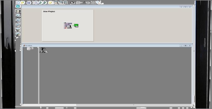
11 Layout This option sets the format of the screen at start up. Figure 8: Layout Dialogue Box with only Functions Page Ticked Function Page ( left hand tick box ): When ticked and a new project is started a window will open, as shown below, allowing functions to be edited. Notes Editor ( right hand tick box ): When ticked and a new project is started a window will open, as shown below, allowing notes to be added to the current project. Figure 9: New Project showing Notes and Functions Windows if both are Ticked Page 5
 Display compiled FireFinder Plus file: Selecting this tab option will display the compiled FireFinder PLUS file.")
12 Compile Set options to display the compiled file and to choose whether to validate included text as functions. In most instances these will both be set to be on. Figure 10: Compile Dialogue Box General Options ( left hand tick boxes in Fig 11 ) Display compiled FireFinder Plus file: Selecting this tab option will display the compiled FireFinder PLUS file. This means that, after compiling the project the *.dat file is displayed in a window on the screen. This is mainly for the advanced user and is usually not selected. Add Notes to FireFinder PLUS File: Allows notes to be added to the file. Validate included text as functions: This feature is used when SPECIAL functions are included in a project. SPECIAL functions are functions that are written in text form and included in the project in the INCLUDED file. Save changes before compiling: Automatically saves any changes before compiling. Warnings ( right hand tick boxes in Fig 11 ) A warning will be indicated during the Compiling process that the checked features do not meet the required criteria and must be corrected. Un-zoned Sensors Functions Without Outputs Missing Graphic System Maps Page 6


13 Project Settings: Set the Options for the project Default Customer Text: Here 4 lines of default customer text (e.g. name) are entered. This saves having to enter the company's name for every configuration. Figure 11: Project Creation Dialogue Box Increment Function Copies: Click on the tick box to enable. Enable when copying or cloning Functions to automatically increment the number of the device s inputs and outputs (1 to 3). Should a mistake be made when numbering the device, an error message will appear. Automatic Backup: Select the timing for automatic periodic backup of the project from the drop down box (5, 15, 30, 45, 60 minutes or NEVER). Default Country: Set by default (hence greyed out) to the country where the panel is to be installed. Auto Zone Allocation Value: Open the drop down box to select a value (0-999). This will automatically assign zones when making multiple entries in the Module Data Entry screen. Auto Zone Allocation Enabled: Click on the tick box to enable the auto zone allocation Communications This tab will display a page to set the port and methodology used to communicate with the FireFinder PLUS. Figure 12: Communication Dialogue Box Page 7
 CN28 CN8 R20 R64 COMMS 2 RS232 CN27 NOTE: CN8 (TOP) & CN27 ARE BOTH TH1 CN2 COMMS 2")
14 Normally; Communications Port: Comms Default Port is 2. MAIN BOARD BRD86MBA R56 COMMS PORT 2 R25 R19 SHIELD CN27-10 WAY IDC CONNECTOR RD TD PIN 1 27V IN COMMS2 RS232 (TOP) CN28 CN8 R20 R64 COMMS 2 RS232 CN27 NOTE: CN8 (TOP) & CN27 ARE BOTH TH1 CN2 COMMS 2 IN CFM RS485 EOL Q5 LK2 R55 R58 C90 R57 C82 LK3 CN21 C83 BUZZER INHIBIT COMMS1 RS232/MODEM (BOTTOM) EXPANSION PANEL CN3 EXPANSION LEDS RN6 COMMS PORT 1 C89 EXPANSION MODULE + CN9 BUZZER OUT COMMS PORT 3 Figure 13: Comms Port Location on the Main Board and Port Numbering BZ1 U32 CN25 RN16 RN17 ZDN2 COMMS 3 USB Note: The modem I/O port is a Dual DB9 connector (CN8 situated on the lower left hand corner of the Main Board) is normally used for programming of the FACP via the serial port of a PC. There is also a USB connector (CN25) provided to allow programming of the FACP from a USB port of a PC. Default Communications Speed: The speed or baud rate of the communications used to communicate to the FireFinder PLUS and no adjustments are required by the user. Default speed is bps. Default Phone Number: Enter the phone number to be auto dialed for modem connection Use Modem Connection for Transfer Wizard: Tick if the Transfer Wizard is to be used as the communication vehicle. Use Modem Connection for Remote Control: Tick if remote control is via a modem data. Use Hardware Flow Control (RTS/CTS): Tick if hardware control is used for the transfer of File Association Tick the check box if the project *.ffp files are to be associated with ConfigManager Plus - Australia. Note: The displayed message confirms the status Figure 14: File Association Selection Box Page 8


15 Apollo Input/Output This tab sets the default zone configuration of the Apollo/AMPAC loop device s inputs when a IO device is added to the loop. Each is simply selected by clicking on the appropriate check box. This setting is used when the loop module is first created. For example, if the First input active only is selected, then new IO device that is added subsequently will have its first input automatically set to General and the remaining as Inactive ; if the All inputs active is selected, then the new IO device will have all its inputs set to General automatically. Figure 15: Apollo Input / Output Screen Note: Only one choice can be selected First input active only: Tick if required or All inputs active: Tick if required Window Note: New Project, Functions and Notes will only be shown if they have been ticked in the Layout selection screen Figure 16: Window Drop Down Box Cascade - Displays windows stacked and cascading from the top left to the bottom right of the screen. Tile Horizontal - Displays Project and Function windows top edge to top edge. Tile Vertical - Displays Project and Function windows right edge to left edge. Arrange Icons - Arranges minimised image windows within the program screen. Minimise All - Iconizer s all active windows to the bottom left hand corner of the screen. Restore All - Returns all active windows to those selected prior to Minimise All. Page 9

 and communication")
16 3.1.5 Help Figure 17: Help Drop Down Box Contents This is the on screen help file that provides a PDF version of this manual. About Displays the following screen giving the user the Version of ConfigManager PLUS being used, direct access to the Ampac website (highlighted in blue) and communication access (highlighted in blue). Figure 18: About Screen Page 10


17 4 Creating a New Project To create a new project either click on the New Project Icon on the tool-bar, Ctrl + N or; Figure 19: Selecting a New Project Select: File/ New Project. This will bring up the System settings dialogue box as shown below. Note: Remember the Options / Environmental Settings MUST be entered before starting a new project. 4.1 The Systems Settings Dialogue Box Base Settings Figure 20: The System Settings Dialogue Box Enter all the information described in the sub-headings set out below. Once completed press OK. If there are any errors the operator will be prompted to correct them. Note: To edit System Settings at a later date click on the Globe icon in the Tool Bar. Project Enter the project name. Naming is optional though it is advisable to make projects distinctive so they are easily identifiable at a later date. Country The drop-down list box defaults to the country particular to the version of software and takes into consideration the different panel functionality in different countries (not editable). Standard The drop-down list box defaults to the national standard particular to the version of software (not editable). Language The drop-down list box displays the default language being used for the standard (not editable). Page 11

. Figure 22: The Quick Set Dialogue Box Selecting Graphic Interface Page 12")
18 Protocol Use the drop-down list box to select the required option to become active. FireFinderPlus Version Displays the configuration structure s version currently in use (not editable) Display settings The display settings, sets the LCD message that will be displayed when the FireFinder PLUS LCD is in its normal state. The text on each line may be up to 40 characters long. Figure 21: The Display Settings Dialogue Box System Interface (SmartGraphics) The Graphic Interface Fitted check box is selected if a SmartGraphics Interface is being installed in the system. This tick box turns on the Map allocation column in the Loop Device configuration spreadsheet (Refer section 5). Figure 22: The Quick Set Dialogue Box Selecting Graphic Interface Page 12
. DGP s Data Gathering Points (DGP s).")
19 4.1.4 Quick Set settings This option will save a considerable amount of work as it will automatically set up the required number of panels, DGP s and / or mimics. Figure 23: The Quick Set Dialogue Box Panels This sets the number of panels in the system. For non-network projects this will be set to one (1). DGP s Data Gathering Points (DGP s). This entry is used if DGP s are configured on a network. DGP s being a Slave FACP that, has no front panel controls, communicates directly with and is under the control of the Master FACP Configuration Version Allows editing of the configuration versions for ease of traceability Figure 24: The Configuration Dialogue Box The major and minor version information indicates changes that are made via the ConfigManager PLUS and FireFinder PLUS respectively. Page 13

20 That is, Major Version: Each update via the ConfigManager PLUS increments the Major Version Number and clears the Minor Version Number to zero. Minor Version: Each update via the FireFinder PLUS panel s programming increments the Minor Version Number. Note that if the Major or Minor version number reaches 65535, it shall then remain at this value unless being reset manually via ConfigManager PLUS. On the creation of a new configuration for the first time, ConfigManager PLUS software defaults both the Major and Minor Version Number to zero Global Settings Alert Tone Global Setting The Global Alert Tone pulse ON and OFF times can be set here ADF Timeout Global Setting The default timeout for ADF groups can be set here. This will override all previous ADF timeouts that may have been set at on the Module Data Spreadsheet. Figure 25: The Sounder Settings Dialogue Box Page 14


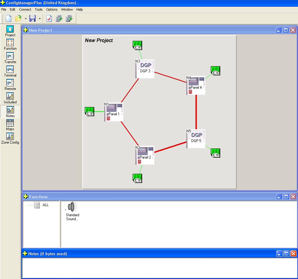
21 4.2 The New Project Screen When all of the options above have been determined and the OK button has been clicked the following screen will be displayed. This may vary depending on the options selected in the layout options dialogue box. Each of these areas will be discussed in detail on the following pages. Figure 26: New Project Screen Figure 27: New Project Screen with Cross Hatch Screen Note: The cross hatch screen is used to move the Project Screen around the Monitor Screen so as to locate or centre specific parts of the system. For larger systems with multiple panels a panel can be selected from the drop down screen, selecting Go and that panel is automatically centered. Page 15


22 4.3 The Project View The screen below is a typical view that will be seen by the operator when a single panel is to be programmed. The Panel represents the hardware which is common in all panels. C1 represents the controller that interfaces with up to 8 slave modules. Note: It is recommended that the panel section is programmed first followed by the controller. Figure 28: The Project View with Edit Options for the Panel & Controller It is possible to edit the parameters of the panel by right clicking on the icon as shown above. Similarly it is possible to edit the module types as shown Panel Settings or Editing Double click on the Panel to set or edit the Panel configuration. Figure 29: The Main Information Edit options for the Panel Note: Click on OK to go to or return to the main project screen at any time. Main Information (Edit) Shown above is the default screen ready for the Main Information to be entered. Description: Default is Panel 1. This can be changed to a more apt description by simply deleting the text Panel 1 and typing a new description. This description will appear next to the panel in the Project screen. Page 16
.")
23 Reference: Node number of the Panel (Networking). Default is 1 for a single panel and the node NX number as seen in the Project Screen for network panels. Default Display: Type in the preferred FACP LCD front panel default information. (Default empty). Network Parameters: Right click on the Panel Icon and select Edit Network Parameters to set Global Access. Figure 30: The Panel Access or Network Parameters Screens If Global Access is assigned to a Panel they will see or monitor the entire system. If it is not set then the various panels, Loop/s and Group/s will have to be assigned by way of the Set Access screen. In other words the panels Loop/s and or Group/s that a Panel, DGP and / or Mimic will see or monitor must be individually entered Setting or Editing the Controller Module Types: Figure 31: The Edit options for the CONTROLLER Edit Loop Modules Right click on the Controller and select Edit Loop Modules Types from the drop down screen. Using the Classic screen click the down arrow within the Type column to display the drop down box from which the module type is selected by clicking on it. Page 17
![The Description and Ref [Reference] No [Number] is automatically assigned. The reference number represents whether the module is the first, second, third etc. of its type.](/docs-images/71/65756782/images/24-1.jpg "For example if two Apollo modules are fitted the first module would have a ref. No. 1 and the second module would have the number ref No. 2. These numbers are unique over the whole system.")

24 The Description and Ref [Reference] No [Number] is automatically assigned. The reference number represents whether the module is the first, second, third etc. of its type. For example if two Apollo modules are fitted the first module would have a ref. No. 1 and the second module would have the number ref No. 2. These numbers are unique over the whole system. They are generated automatically and should not need to be altered. For advance users the numbering does not have to be continuous and can be altered to suit specific applications. Alternatively the Graphic screen can be used. This screen uses the click and drag method where the module type from the top of the screen is clicked on and dragged to the required position 1 to 8. Figure 32: Edit Loop Module Type 'Classic View' Figure 33: Edit Loop Module Type 'Graphic View' Rearranging Module Order Method 1: Select Graphic then click and drag each Module into the required order. Method 2: Select Classic. Save and Import the modules to be rearranged. This is done by changing the Type to Not Fitted and selecting OK, the drop down screen shown below will appear, click Yes, then Save to a preferred file location. To reapply or Import a Module select the Controller Configuration option Graphic, select the available Module number then Import Module, repeating the Page 18
25 process in the desired order for each Module. Page 19

26 4.3.3 Addon Module Types Figure 34: Warning Pop up Box Right click on the Controller C1 and select Edit Addon Module from the drop down screen. Click the down arrow within the Type column to display the drop down box from which the Addon module type is selected by clicking on it. The Addr No is automatically assigned as is the physical address (dip switch) of the module in question. Click on the Edit button to configure the Addon module. Note: Selecting an Agent Release and Fan Control (with Termination Board Fitted) automatically reserves the next record observe that the next record is disabled and greyed out as seen below - Addon Ref No 6 and 8. Figure 35: Controller Edit Addon Module Types Controller (Loop and I/O) Setting or Editing To access the Controller Setting / Editing facility double left click on the Controller C1 Edit LOOP Modules. To physically edit each Loop Device parameter left click in the appropriate square and enter or change the existing setting / information. Refer to section 5 for full editing details of Loops and devices. Page 20


27 Figure 36: Controller Settings - Apollo XP95 Loop Module Edit Module Input / Output. Here the Input and Output descriptions can be edited and the Inputs and Outputs can be made active / inactive. To physically edit the description click in the box and edit from the keyboard in the normal way. To set an Input or Output to active / inactive double click on the Y [Yes] active or N [No] inactive. Note the Input will automatically change to Y (yes) if an Input Description is inserted. This can be made inactive again by double left clicking on Y Input Output settings Input setting only Output setting only Displays Both Inputs and Outputs Displays Inputs only Displays Outputs only For Input / Output settings the Input/Output module page displays: 1. The input (or output) numbers 2. An associated Type In descriptor 3. An option to determine if the input (or output) is to be active. To select if a module is to be active or inactive left-click on the box to toggle the contents between Y(Yes) or N(No). To enter the descriptor just left-click on the box where you want to enter the data and type it in. = Figure 37: Controller Setting - Input / Output Module showing I/P and O/P Selection Page 21

28 = Figure 38: Controller Setting - Input / Output Module showing I/P Selection Only = Figure 39: Controller Setting - Input / Output Module showing O/P Selection Only Page 22

29 4.4 Controller Settings (Addon Modules) Right click on the Controller C1 and select Edit Addon Module from the drop down screen. Click on the Edit button to configure the desired Addon module. This section gives an overall view of the Addon modules and a more detailed explanation of them is covered in the Addon Modules section Edit Brigade Board It may be necessary to select the first Input and change the Config Type to MCP in the first instances to be able to edit this facility. Select Brigade from the Config Type column on the Addon Module page and click on the Edit button. Clicking on the Edit MCP Property button displays the dialogue box for the MCP input configuration. Each Card [Brigade (X)] is automatically allocated an identity of number 1, limited to one per node and must be the first Addon Reference module if fitted. Figure 40: Controller Edit Addon Brigade Module Description: This field is editable Figure 41: Brigade Board Description Field Supply / Battery Size: This field is set via the drop down boxes for the power supply and size of the batteries installed. Page 23


30 Figure 42: Brigade Board Supply and Battery Size Info9rmation setting Pulse On/Off Time: These settings are meant for the Brigade board Outputs configured as Alarm Device outputs ( alert tone). Figure 43: Brigade Board Alert Tone On Off Times Brigade Inputs: Description: There are 4 inputs available and each can be configured for a different purpose based on its Config Type normally describing the location of the Brigade Board. Click in the box to enter the description. Note: that only the first input can be configured as an MCP for Editing purposes clicking on the Edit MCP Property button brings a window for the configuration of the MCP settings. Config Type: Figure 44: Brigade Module Config Type Input Options Input EOL: - The available options for are. Figure 45: Brigade Input EOL Options Brigade MCP Property Settings: Config The available options for Config are Latching and Non Latching. Page 24
31 Figure 46: Controller Edit Addon, Brigade Module Config Latching MCP Page 25
 are used to determine which outputs will be")


32 Figure 47: Controller Edit Addon, Brigade Module Config Non-Latching MCP Brigade MCP Outputs: Five checkboxes (Ancillary, Fire/FARE, Warning System, Fire LED, and Sprinkler) are used to determine which outputs will be activated by MCP when activated. MCP Groups The Group column allows the user to enter up to 6 group numbers that are associated with I/O programming that will be activated when the MCP is activated Brigade Monitored Outputs There are 4 outputs available and each can be configured for a different purpose based on its Config Type. Figure 48: Brigade Output Selection Options Output EOL - The available options for EOL are. Page 26


33 Output - Normally Energised The checkboxes defines the state of the outputs when the panel is in the Normal state. Outputs configured as Fault default to Normally Energised Figure 49 Sounder Groups Sounder Groups are only available to outputs configured as Alarm Devices. Figure 50: Sounder Group Allocation Entry Brigade Relays/Outputs: There are 5 relays available and each can be configured for a different purpose based on its Config Type. The available options for the Config Type are; Figure 51: Relays Config Type Selection Options Relay - Normally Energised The checkboxes define the state of the relays when the panel is in the normal state. Figure 52: Relay Normally Energised Settings Note: Default Normally Energised settings above. Page 27
![4.4.2 Edit 8 Way Conventional Zone Note: Each Card [8 Way Conv Zone (X)] is automatically allocated an identity of number 1 to 15.](/docs-images/71/65756782/images/34-1.jpg "Select 8 Way Conv Zone from the Type column on the Addon Module page and click on the Edit button.")
34 4.4.2 Edit 8 Way Conventional Zone Note: Each Card [8 Way Conv Zone (X)] is automatically allocated an identity of number 1 to 15. Select 8 Way Conv Zone from the Type column on the Addon Module page and click on the Edit button. Figure 53: Controller Edit Addon 8 Way Conv Zone Module Description: Normally describe the location of the 8 Way Conv Zone. Click in the box to enter the description. Figure 54: General Setting Description / EOL Box EOL: This defines the end of line setting for the 8 circuit inputs on board. Figure 55: EOL Selection Drop Down Box Circuit ( 1 to 8): The circuit number is set and cannot be modified. Zone: The zone number must be a number between 1 and Description: The description is limited to 33 characters and may contain numbers or characters. Type: There is two types to choose from: Normal: default setting Combined: short and open circuits generate an Alarm condition.( New Zealand Feature) Type Descr: The type descriptor is automatically entered by the program. This may be modified if required but it is limited to 6 characters. Page 28
35 Device Cnfg: The Device Configuration column uses a drop down list box to display the options that a device may be set to; these are; Figure 56: Device Configuration Drop Down Box Time Out: This column is the used to enter the time out for the Self Reset configuration. A maximum of 999 seconds is allowable (60 seconds is considered a norm). An error message will be displayed if the operator attempts to enter something greater than 999 seconds. ANC, WARN SYSTEM, Fire/FARE, SPRNKLR: These columns can be set to yes or no. If yes any outputs programmed as these types will activate when the applicable Zone is active. Fire LED: The Fire LED refers to the Front Panel Fire LED (i.e. determines if an alarm event on the device in question is added to alarm buffer). This normally set to Yes. Groups: The next six columns allow the user to enter up to 6 group numbers against each device. These group numbers are only used for I/O programming. Page 29
] is automatically allocated an identity of number 1 to 15.")


36 4.4.3 Edit 32 Way Indicator Card Select 32 Indicator Card from the Type column on the Addon Module page and click on the Edit button. Each Card [32 Indicator Card (X)] is automatically allocated an identity of number 1 to 15. Description Normally describes the location of the 32 Indicator Card. Click in the box to enter the description. Select Board Type: There are three board types that can be chosen from refer to image below. The required board is selected by checking the appropriate board. Figure 57: Board Type Selection Zone LED Statuses: These have default configurations depending on the Board Type Selected and are only applicable when the LED s are set for Zone Activation. Figure 58: Zone LED Statuses To alter the activation Input Type double click on the Activation field and edit using the pop up screen. Page 30

37 BRD43ZAMC (Bi-Coloured LED) option This board allows for the configuration of the LED colour and mode as long as the Activation is not a zone input. A zone input in the Activation column disables the corresponding columns for LED colour and mode. Figure 59: Controller Edit Addon 32 Indicator Card Page 31

38 BRD43LEDM (External LED) option This board does not allow for the configuration of the LED colour and mode as the LED s are hard wired LEDs connected to the board. The setting for the Zone LED Status is limited to either the first two or last two selections. These limitations are due to its single LED characteristics of the board. The Buzzer Enabled option (if ticked) allows the on board buzzer to operate. This is generally used when the BRD43LEDM is mounted external of the Fire Panel. (This option is not available in the NZS4512 verasion). Figure 60: Controller Edit Addon 32 Indicator Card Page 32

39 BRD43ZAMC (16 Zone) option This option only has 16 Zones and only allows Zone Activation therefore the Zone LED Statuses will always apply. There are two LED s associated with each Zone. A Fire/Alarm LED and a common Disable/Fault LED. Figure 61: Controller Edit Addon 32 Indicator Card Page 33
 The description should be a name given to the SmartTerminal or its physical location Reporting Parameters Double click in each of the Report boxes to display and set the, Y (Yes")

40 4.4.4 Edit SmartTerminal/NFS SmartTerminal Select Smart Terminal from the Type column on the Addon Module page and click on the Edit. Description (Type in) The description should be a name given to the SmartTerminal or its physical location Reporting Parameters Double click in each of the Report boxes to display and set the, Y (Yes reports the parameter) and N (No does not report the parameter) Alarms, Faults, Disables parameters that SmartTerminal will display on each SmartTerminal at each location. Figure 62: Smart Terminal Set up Screen & Global Access is Set by Network Parameter _ NFS NOT ENABLED Note NFS is used when a Nurse Fire Station SmartTerminal is installed. Note: When NFS Enable is set to N then the columns (Report Alarms/Fault/Disable, Global Master Reset and Network Parameter) are enabled (i.e. not grey out), and the columns (NFS Group/Ack Timeout/Inv Timeout) are disabled (i.e. grey out). Figure 63: Smart Terminal Set up Screen NFS ENABLED Note When NFS Enable is set to Y then the columns (Report Alarms/Fault/Disable, Global Master Reset and Network Parameter) are disabled (i.e. grey out), and the columns (NFS Group/Ack Timeout/Inv Timeout) are enabled (i.e. not grey out). Note: A maximum of 30 SmartTerminal s can be used in the configuration of the FACP and Each Card [Smart Terminal (X)] is automatically allocated an identity or a number 1 to 30. Page 34
41 Page 35

 is used or unavailable: Figure 64: Agent Release Error Message Next Record Used or Not Available Figure 65:")
: Each Card is automatically allocated an identity in the form of a number 1 to 8.")
42 4.4.5 Edit Agent Release Select Agent Release from the Type column on the Addon Module page and click on the Edit button. Note: An Agent Release Addon module always has a termination board fitted and therefore the next record is automatically reserved for it ( as shown below. Observe that the next record is disabled and greyed out automatically after the OK button is clicked. An error message will be displayed if the next record (required for the termination board) is used or unavailable: Figure 64: Agent Release Error Message Next Record Used or Not Available Figure 65: Note the Addon Ref No / Type is Greyed for the Termination Board Description: Description would normally describe the location of the agent release point. Click in the box to enter the description Agent Release (X): Each Card is automatically allocated an identity in the form of a number 1 to 8. Figure 66: Controller Config Edit - Agent Release Set Up Screen note both drop down boxes can not be selected at the same time Agent Type: The Agent Type can be selected using the drop down screen and clicking on the preferred type. The types are; Constant: The agent is released until the source has been emptied of its contents Solenoid: The agent is released under the control of a solenoid valve fitted to the source of the agent Pyrogen / Metron: Pyrogen / Metron are specialised release products Pressure Switch: Again use the drop down box to allocate the type of contact the release mechanism uses, N/O (Normally Open), N/C (Normally Closed) or N/O MECH (manual) activation with an alarm. Page 36
: Automatic discharge of the agent can be delayed by up 255 seconds. Click in the box and type in the required delay.")
43 No Of LCS s: The number of Local Control Station, 1 to 7, is entered by clicking in the box and typing in the identifying number of the LCS. Pre Discharge Delay (Auto): Automatic discharge of the agent can be delayed by up 255 seconds. Click in the box and type in the required delay. If the delay entered is greater than 255 an error message will be displayed. Pre Discharge Delay (Manual): Manual discharge of the agent can be delayed by up 255 seconds. Click in the box and type in the required delay. If the delay entered is greater than 255 an error message will be displayed. Dual Activation: Dual Activation is set to yes Y if two Activation 1 to 4 inputs are required to activate stage 1, stage 2 release. Activation 1 to 4: To set the input, double click within the Activation 1 to 4 box of each for card and use the Edit Input dialogue box to set the type of input which is to activate release. The sequence is, if any of the inputs are activated stage one will commence, when the second input from the list is activated stage 2 will be initiated. Figure 67: Activation 1, 2, 3, 4 Edit Input Dialogue Box The Edit Input dialogue Box is used to enter all information relating to the selected Activation column. First select the type of input (eg. Group etc) then use the keypad to enter the specifics of the input (eg Group number ). Changing or Entering Data; < = backspace deletes single entries, D = highlights data and Delete, Tab( keyboard ) = Tabs to the next box. Note: To remove an entry all together left click within the Activation entry box and CUT. Page 37

44 4.4.6 Fan Control Select Fan Control from the Type column on the Addon Module page and click on the Edit button. Note that there are three modes for the Fan Control Termination board setting Not Fitted, Fitted and Link To. Selecting Fitted will reserve the next record for the termination board similar to the agent release Addon module. Selecting Link To indicates dual control of the fan control card in question and the card that it is linked to. Each Card [Fan Control (X)] is automatically allocated an identity or a number 1 to 15 and is each associated with Fan 1 to 4. Description Normally enter the location of the Fan Control Card. Click in the box to enter the description. Figure 68: 3,4,5 Wire Options with Termination Board NOT Fitted (greyed out areas are not programmable) Termination Board Tick as required. A Node and Addon Ref No must be added if Link To is used There are three modes for the Fan Control Termination board setting 1. Not Fitted (Loop based fan control), 2. Fitted (Panel based fan control) and Link To. Double click on the Termination Board edit box brings out a window for the termination board setting. Selecting Fitted will reserve the next Addon module record for the termination board similar to the agent release Addon module. Selecting Link To indicates a dual control of the fan control card in question and the card that it is linked to. Master Reset - Tick Enables Master Reset of the Fan Controls Page 38

 utilises the Termination Board to control and monitor the fans. Settings are entered directly into the screen shown below (Termination Board set to Fitted ).")
45 Figure 69: Controller Config Edit - Fan Control 3,4,5 Wire and Anc. Disable/ Latch Set Up Screens Note both drop down boxes can not be selected at the same time and greyed out areas are not programmable If the next Addon module record is used or unavailable, the Fitted checkbox will not be made available for user selection in the Termination Board window as shown in the following: Figure 70: Fan Control Termination Board Not Available Message Panel Based Fan Control ( Fitted ) utilises the Termination Board to control and monitor the fans. Settings are entered directly into the screen shown below (Termination Board set to Fitted ). To set the input, double click within edit box of the Latch Reset Input, Fan Alarm (1 & 2) and Fan Inhibit (1 & 2) and use the Edit Input dialogue box to set the desired input accordingly. Note: that this mode does not permit the Out: Start/Stop and In: Run/Stop/Fault settings since they are driven via the termination board directly. Page 39
46 Page 40
 and Fan Inhibit (1 & 2) and use the Edit Input dialogue box to set the desired input accordingly.")
 This configuration normally interfaces to the FACP via a 3I/O Module.")
47 Panel Based Fan Control ( Fitted ) Utilises the Termination Board to control and monitor the fans. Settings are entered directly into the screen shown below (Termination Board set to Fitted ). To set the input, double click within edit box of the Latch Reset Input, Fan Alarm (1 & 2) and Fan Inhibit (1 & 2) and use the Edit Input dialogue box to set the desired input accordingly. Note that this mode does not permit the Out: Start/Stop and In: Run/Stop/Fault settings since they are driven via the termination board directly. Figure 71: Fan Control With Termination Board Loop Based Fan Control ( Not Fitted ) This configuration normally interfaces to the FACP via a 3I/O Module. Settings are entered directly into the screen shown below (note Termination Board set to Not Fitted ). To set the input, double click within edit box of the Latch Reset Input, Fan Alarm (1 & 2), Fan Inhibit (1 & 2), Out: Start/Stop and In: Run/Stop/Fault, and use the Edit Input/Output dialogue box to set the desired input/output accordingly. Note the following: 3 Wire permits Out: Start/Stop and In: Run settings 4 Wire permits Out: Start/ Stop and In: Run/Stop settings 5 Wire permits Out: Start/ Stop and In: Run/Stop/Fault settings Figure 72: Fan Control Termination Board NOT FITTED Page 41


48 Dual Fan Control ( Linked To N:x A:y ) This configuration permits a two way fan control in a networked system by linking a fan card to another. For example, pressing the fan start button on the linked to fan card has the same effect on the fan card that is being linked to and vice versa. Note that in this mode, only the description fields are available for user input since it uses the same configuration as the fan control that it is linked to. Figure 73: Fan Control with Dual Control Description Enter a descriptive location of the Fan Fan Set - Select 3 wire, 4 wire or 5 wire system to be used. Ancillary/Latch Reset Input - select the required input Page 42


49 Fan Alarm Inputs (1), (2) - Double Click in blank space of the appropriate Fan to Edit Fan Alarm Inputs via the pop up screen below. Figure 74:Edit Fan Alarm Inputs Fan Inhibit (1), (2) - Double Click in blank space of the appropriate Fan to Edit Fan Inhibit Inputs via the pop up screen below. Note: when the Termination board is fitted this input will be disabled. Figure 75: Edit Fan Inhibit Page 43


50 Out: Start and Out Stop Setup Pop Up Screen Figure 76: Edit Out: Start and Out Stop In: Run, In: Start, In: Stop In: Phase Fault Setup Pop Up Screen Figure 77: Edit In: Run, Start, Stop Note: When a Termination board is fitted these Out and IN selections will be disabled. Page 44
51 Page 45
] is automatically allocated an identity or a number 1 to 15.")

52 4.4.7 Edit Switch and Indicator Select Switch & Indicator from the Type column on the Addon Module page and click on the Edit button. Each Card [Switch & Indicator (X)] is automatically allocated an identity or a number 1 to 15. Figure 78: Edit Switch & Indicator Set Up Screen with Momentary Switch Selection Input Type Figure 79: Edit Switch and Indicator Set Up Screen with Toggle Switch Selection & Time Out First enter a functional descriptor for the switching operation then selecting the SW Type of switching operation Momentary or Toggle. The LED output (Indicator) on the card can be set to be turned onto flashing or steady. Flashing indicates an externally driven activation on the output (Indicator). Steady indicates a visual indication that a toggle on operation is active. There are two modes for the SW Type Momentary and Toggle. Timeout only applies to Toggle switch type. The minimum timeout is 0 and the maximum is seconds. A timeout value of zero implies no timeout that is, manual action from the user is required to reset the previously latched condition. Externally driven activation on LED output (i.e. Indicator) only applies to Momentary switch type. Momentary Time out of course will not be selectable and the Input shall be set by double clicking Page 46
53 in the appropriate switched line under Indicator and setting the Input Type via the Pop up screen. Page 47

] is automatically allocated an identity of number 1 to 15.")
54 Figure 80: Edit Switch Indicator Momentary Input Type Selection Pop Up Screen Toggle Selecting Toggle will result in the operator being requested to enter a Time Out period of operation via the Pop Up Screen shown below. Figure 81: Set Toggle Timeout Pop Up Screen Edit 8 Way Relay Board Select 8 Way Relay from the Type column on the Addon Module page and click on the Edit button. Each Card [8 Way Relay (X)] is automatically allocated an identity of number 1 to 15. Firstly enter a Description of the relays operation then double left click on the appropriate line under Activation to select the input to operate the relay. Figure 82: Edit 8 Way Relay Board Screen and Control Input Settings ( Assigned Point) Pop Up Screen Page 48

] is automatically allocated an identity of number 1 to 15. Description would normally describe the location of the 16 Way Input Board. Click in the box to enter the description.")
55 Activation: Double click on the Activation column box of the corresponding output and enter the desired activating condition of the output in question. Figure 83: Activation Input Pop Up Selection Screens for each Input Type Anc.: This column allows you to associate the selected relay with the Ancillary Disable button Edit 16 Way Input Board Select 16 Way Input Board from the Type column on the Addon Module page and click on the Edit button and enter a functional descriptor for each input Each Card [16 Way Input Board (X)] is automatically allocated an identity of number 1 to 15. Description would normally describe the location of the 16 Way Input Board. Click in the box to enter the description. These inputs are designed to be used externally e.g. by way of a Function. Figure 84: 16 Way Input Board Entry Screen Page 49
] is automatically allocated an identity of number 1 to 3.")
56 Edit HLI Expander Select HLI Expander from the Type column on the Addon Module page, click on the Edit button and enter a functional descriptor for each input. Each Card [HLI Expander (X)] is automatically allocated an identity of number 1 to 3. The valid combination for this Addon module is 1 x High Level Interface, 1 x Graphics System Interface / Modbus Interface and 1 x EV3000 HLI. Note: that it is invalid to have both Graphics System Interface and Modbus Interface in a node. Description would normally describe the location of the HLI expander. Click in the box to enter the description. Interface Type Select ( Check ) the appropriate interface type from the four displayed. High Level Interface This provides a text based output for dumb interfaces like Nurse Call and Paging Systems. Figure 85: HLI Settings Pop Up Screen High Level Interface (HLI) Graphics System Interface This provides for a 2 way interface for the AMPAC SmartGraphics interface system. The Graphics Folder is used to define the location of where the SmartGraphics files (tag_copy.ci, advalm.dbf, variable.dbf) are to be written to. The Graphics Unit Name is used to prefix the values for Tag, Desc and Expr in the advallm.dbf file, and the Name in the variable.dbf file. The Graphics Unit Name Tag Prefix is used for the Unit in the variable.dbf file. Note: the above are system wide settings for Folder, Unit Name and Tag Prefix and is applied to all Graphics System Interface Addon modules. Page 50


57 Figure 86: HLI Settings Pop Up Screen Graphics System (Smartgraphics) Interface Modbus Interface This provides for a 2 way intelligent Modbus RTU standard interface for BMS and PLC based systems. Figure 87: HLI Settings Pop Up Screen Modbus Interface Edit EV3000 HLI Interface This provides for an intelligent interface for connection to the AMPAC EV3000 EWIS system. Figure 88: HLI Settings Pop Up Screen EV3000 HLI Page 51
] is automatically allocated an identity of number 1 to 15. Description would normally describe the location of the 8 Way Sounder.")
 The valid input for a sounder group is 0 to 255. 4.4.12 Zone Control Card Select Zone Control Card from the Type column on the Addon Module page, click on the Edit button and enter a functional descriptor for each input.")
58 Edit 8 Way Sounder Control Select 8 Way Sounder Control from the Type column on the Addon Module page and click on the Edit button and enter a functional descriptor for each input. Each Card [8 Way Sounder (X)] is automatically allocated an identity of number 1 to 15. Description would normally describe the location of the 8 Way Sounder. Click in the box to enter the description. Figure 89: 8 Way Sounder Settings Pulse On/Off Time These settings are applied to all the 8 sounder outputs ( Alert Tone). Group (1 4) The valid input for a sounder group is 0 to Zone Control Card Select Zone Control Card from the Type column on the Addon Module page, click on the Edit button and enter a functional descriptor for each input. Each Card [Zone Control Card (X)] is automatically allocated an identity of number 1 to 15. Description would normally describe the location of the Zone Control Card. Click in the box to enter the description. Figure 90: Zone Control Card Zone Allocation Screen Page 52
59 Switch (1 8): Double click on the Switch edit box and enter the zone number in question. Page 53
] is automatically allocated an identity of number 1 and is limited to one per node.")
![Figure 91:Conventional Network Board Setting Local / Global Parameter Global Double click on the Y [ Yes ] sets the board as Global, N [ No ] as Local. 4.](/docs-images/71/65756782/images/60-2.jpg "4.14 Edit Bar Display Card Select Bar Display Card from the Type column on the Addon Module page and click on the Edit button and enter a functional descriptor for each input.")
60 Edit Conventional Network Board Select Conventional Network Board from the Type column on the Addon Module page and click on the Edit button and enter a functional descriptor for each input. Each Card [Conventional Network Board (X)] is automatically allocated an identity of number 1 and is limited to one per node. Figure 91:Conventional Network Board Setting Local / Global Parameter Global Double click on the Y [ Yes ] sets the board as Global, N [ No ] as Local Edit Bar Display Card Select Bar Display Card from the Type column on the Addon Module page and click on the Edit button and enter a functional descriptor for each input. Figure 92: The Edit Bar Display Card Screen & Location Address Input Type Pop Up Screens Reminder - Numeric keypad for data entry < = Delete last or highlighted entry - D = Delete highlighted entry >> = Highlight entry Page 54

61 Edit EWCIE Front Panel Card Select EWCIE Front Panel from the Type column on the Addon Module page and click on the Edit button and enter a functional descriptor for each input. Each Card is automatically allocated an identity of number 1 and is limited to one per node. Up to eight OWS Amplifiers can be programmed to operate with one EWCIE Front Panel Description would normally describe the location of the EWCIE Front APnel. Click in the box to enter the description. Figure 93: EWCIE Front Panel AMP/OUT (1..8) Description Enter a meaningful description for each amplifier fitted in the panel Auto Activation Assign what will trigger the amplifier. Assigned points, groups, Zones, Sensors or logical poinst can all be used. Double Click in the field to bring up the input type box. Evacuation, Alert and Custom Refer to MAN3072 for the detailed programming of these fields. Page 55


62 5 The Module Data (Loop and Device) Entry Spreadsheet Once all the Module data for the panel has been entered, the next step is the entry of specific data for each module. This is done via the Module Data Entry Spreadsheet. To access the Spreadsheet double click on the Controller (C1) Note: If the Controller Configuration Information has not been entered the Controller Configuration Dialogue Box will appear rather than the spreadsheet shown below. The Module Data entry Spreadsheet appears as a window with a row of tabs along the top, one for each module. To enter the data for a module, click on the tab and in the area below a spreadsheet will appear in which you enter the data. Figure 94: Apollo Module Data Entry Spreadsheet 5.1 Type and Device Configuration To select the Type of module or device click on the item from the drop down menu within the spreadsheet or the in the tool bar or right click in the box and use the Select Device as shown above. The screens below are those presented using the icon in the Tool Bar. Figure 95: Device Type - XP95 & Discovery Selections Page 56
 Type If a device is selected, such as I/O Modules, that requires programming or settings the")

 is selected by right clicking within a column")

63 Figure 96: Device Type Series 90 & Ampac Selections The appropriate Device Config is then selected from the second drop down box. Figure 97: Device Configuration (Device Cnfg) Type If a device is selected, such as I/O Modules, that requires programming or settings the More column will indicate this by automatically inserting a in the column. Double clicking on the will open another screen in which control data for that device can be entered. This is covered in more detail later in the manual under Input / Output Settings. Figure 98: Short Cut Selection Window Note: This shortcut selection screen ( as above ) is selected by right clicking within a column within which a selection is to be entered. Select Device categorises the types of devices that can be selected Fill selection is used to fill and number multiple sensors of the same type. This is done by entering the first description or type etc then left clicking on it and dragging the Cursor down to the last desired insertion point. Cut, Copy, Paste and Delete are used to edit either single or multiple entries in the normal way. Page 57
![5.2 The Extended Menu and Toolbar Figure 99: The Extended Functions Menu and Toolbar 5.2.1 File New (Project) [CTRL+N] Select this option to start a new project.](/docs-images/71/65756782/images/64-1.jpg "The Project Manager dialogue box will appear as a result. Open [CTRL+O] Open loads a previously saved project.")
64 5.2 The Extended Menu and Toolbar Figure 99: The Extended Functions Menu and Toolbar File New (Project) [CTRL+N] Select this option to start a new project. The Project Manager dialogue box will appear as a result. Open [CTRL+O] Open loads a previously saved project. The Open Project dialogue box will appear, locate the file to be opened and click on Open. Configuration Files are saved with the.ffc extension. Reopen Re-open allows the user to select from a list of previously opened files. Open Automatic Backup Opens the automatic saved backup file. Save [CTRL+S] This option is initially greyed out until a project has been created or opened a project. It will save the project to the location from which it was opened, overwriting the older version. Note that the operator will not be queried as to whether they want to do this. If working on a new project that has not been saved before the Save Project As dialogue box will appear instead, this is described under the next heading. Save File As This option is initially greyed out until a project has been created or opened. It will bring up a dialogue box to enter the file name to use for the project and to locate or create the folder in which to save it. Close Project This option is initially greyed out until a project has been created or opened. Click here to close the project. A Dialogue Box will asked whether or not to save it, if yes and the project has never been saved before the Save Project As dialogue box will appear as described above. Print Selecting this will bring up the Print dialogue box. From here the printer can be set up. Once everything has been checked select OK and the Module Data Entry Spreadsheet will be printed. Exit To close down the Configuration Module program select Exit. If changes have been made to the current project and have not saved then a Dialogue Box will asked if the operator wishes to save it now. Page 58
65 5.2.2 Edit Undo [Ctrl+Z] This will take the operator back one step in case an error has been made or a change is required while entering data into the Module Data Entry Spreadsheet. Undo can go back up to 20 steps. Holding down Ctrl and pressing Z will also implement this function. Note this function will be greyed out at the start of a project as there will be nothing to undo. Delete [Del] This will clear a highlighted area on the spreadsheet. To highlight an area left click on the spreadsheet and without releasing the mouse button drag it across the area to be selected such that it is all highlighted in black. Alternatively left click on the spreadsheet, then hold down shift on the keyboard and left click somewhere else on the spreadsheet. The intervening area will be highlighted. This function can also select by right clicking on the area to be deleted. This will bring up a menu from which to select Delete. Copy [Ctrl+C] After highlighting an area of the spreadsheet or selecting a single entry click on copy (or hold down Ctrl and press C) to copy it to the clipboard so that it can be pasted into another area of the spreadsheet or into another program. This function can also be selected by right clicking on the area to be copied. This will bring up a menu from which Copy Selection can be selected. Cut [Ctrl+X] After highlighting an area of the spreadsheet or selecting a single entry click on Cut (or hold down Ctrl and press X) to copy it to the clipboard so that it can be pasted into another area of the spreadsheet or into another program. Unlike the Copy function however, the contents of the selected area will be deleted. This function can also be selected by right clicking on the area to be copied. This will bring up a menu from which Copy Selection can be selected. Paste [Ctrl+V] This function will insert the contents of the clipboard into the spreadsheet starting from the currently selected location, assuming the data is applicable to the application. Data can not be pasted from an external application into the spreadsheet via this function, however by right-clicking and selecting Paste Descriptions. Note: Paste can only be done in the Descriptions by this method. Page 59

66 Advanced - This feature allows editing of Module settings / description and to view the default parameters for that module. Note: It is not recommended to adjust any of these settings without consulting Ampac Technical Support Figure 100: Advance Editing of I/O Module Pop up Screen Replicate This feature works by copying the last change made to all selected cells with the same original contents as the cell that was edited. All other cells selected or not, remain unaffected. For example if it was required to change all Heat A devices to Heat C, change one of these devices configuration to Heat C, select all devices, then Edit Replicate. Copy Change To Highlighted When an area is highlighted and a change is made to a selected area, if Copy change to highlighted is used then the change is made to all of the relevant areas in the highlighted section. For View Highlights, add Highlights refer to that Section Replicate On Highlighted When an area is highlighted and a change is made to a selected area, if Replicate on highlighted is used then the change is made to all of the relevant areas in the highlighted section Search Search This option allows the operator to search for text when editing modules. Search Again F3 This allows the user to search for text again. Replace In Description This option allows the user to replace letters or words in the description fields. Page 60

67 5.2.4 View Add Highlights When this option is selected the Select Parameter to Highlight box appears. Select an option as shown and type in a parameter that is referred to in the region selected. In this case the word detector is entered. Selecting OK highlights all devices with the Description - Detector Figure 101: Highlighted Screen Remove highlights This simply removes the highlights on the selected screen. The following three options from the View drop down screen if selected takes the operator directly to the appropriate working screen. Another method of selecting these options is to left click on the icons as shown below. Edit descriptions, groups, brigade settings View input / output settings see also Input /Output Modules Edit day / night settings Page 61
68 5.2.5 Tools Verify Project [F4] This function checks that the project produces a valid FireFinder PLUS configuration file. Any errors will be displayed on the screen. Compile File [F5] This function will create the FireFinder PLUS configuration file for the current project. This is the file that is actually sent to the FireFinder PLUS. A SAVE FILE AS dialogue box will appear so that you can select the file name and location of the file you are creating. The file created is a text file with a.dat extension. By using the Compile tab of the Environment Settings you can select to display the Compiled FireFinder PLUS File and a window will appear showing the contents of the file after it has been generated. Convert File from FireFinder PLUS This will convert the information previously uploaded from the FireFinder PLUS panel into a format such that it can be imported for use by ConfigManagerPLUS. Clean Up Directory Used to cleanup file locations and unused files within that location Transfer Send This function is used to Send either the current project config or a saved project config into the panel/s. It is also used for sending updated application software. Receive This function is used to Receive a panel config from the panel and open it up a project in the programming tool or save to a directory on the pc. Events Log This function is used to download the panels event logs. Page 62
69 5.2.7 Clicking Tool Bar Icons; Project View displays the current project screen Functions View displays the Functions screen Remote Controller displays a graphical screen from which the FACP can be remotely controlled Included Text Editor displays the written Functions screen for editing a written Function Notes Editor displays an enter text screen for storing note on the project Modules Edit View displays the modules in the configuration for editing, adding or deleting Maps displays the map name and the description of each page in the graphics configuration Figure 102: Entering Map Names and Screens Main Map with no Sub Map To set up a main map with no sub map -> provide a map name for the Parent Map Name and leave the Sub Map Name blank. For example, set Map (row) 1: Parent Map Name = "mainmap" and leave Sub Map Name blank. Main Map with 2 Sub Maps To set a main map with 2 sub maps -> use the same map name for the Parent Map Name of two records and provide an unique Sub Map Name for each. For example, set Map (row) 1: Parent Map Name = "mainmap" and set Sub Map Name = submap1; set Map (row) 2: Parent Map Name = "mainmap" and set Sub Map Name = submap2. "tagcopy.ci" file includes a function PageSum that stores the parent-sub map records information. Note that a parent map with no sub maps will not be added to this function. Page 63
 Day/Night: 1. If set to Y, both the Day Mode and Night Mode settings will be used by the FACP. 2.")

70 5.3 Zone Configuration Options Zone Config displays the zone table configuration of the system. This is used to set zone(s) into its respective mode (i.e. Normal, dependency A/B/C or Delay-to-output) based on the BS EN and AS CIE standards. Description: Zone description (e.g. location details) Day/Night: 1. If set to Y, both the Day Mode and Night Mode settings will be used by the FACP. 2. If set to N, only the Day Mode settings will be used. Day Mode or Night Mode: Allows the Zone to be configured and operate in one of the six modes as follows depending on the time of day/night: Normal: Figure 103: Normal Zone settings No special zone functionality. Zone alarms and outputs are immediately activated Dependency A (EN54-2 and AS7240-2): Figure 104: Dependency A settings When a device in this zone goes into alarm the first alarm signal from the device is not reported and the fire alarm condition is inhibited until a confirmation alarm signal from the same detector or another detector in the same zone is received. The confirmation time is set to 60 secs and can not be changed. Time Out 1 is used to set the time to cancel the initial alarm state. This can be set from 60 seconds up to a maximum value of 1740 seconds. If there has been no confirmation alarm during the first 60 seconds the time Out 1 counter starts. If another alarm is received during this time the Zone will enter the full alarm state without requiring a confirmation alarm. Note: Dependency A zone settings DO NOT apply to Manual Call Points configured in the zone Page 64
71 Page 65


 or any")
72 5.3.3 Dependency B (EN54-2 and AS7240-2): Figure 105: Dependency B settings When a device in this zone goes into alarm the first alarm signal from the device is indicated on the panel but the fire alarm condition is inhibited until a confirmation alarm signal is received from another detector in the same or different zone. Time Out 1 is used to set the time to cancel the initial alarm state. This can be set from 300 seconds up to a maximum value of 1800 seconds. A manual Reset will also cancel the initial alarm state. If there has been no confirmation alarm during the first 60 seconds the time Out 1 counter starts. If another alarm is received during this time the Zone will enter the full alarm state without requiring a confirmation alarm. Time Out 2 column allows the user to configure whether the different confirmation zones are co-sited (that is a zone that is next to the zone determined by a Group number) or any zone. Figure 106: Dependency B Zone Grouping Note: Dependency B zone settings DO NOT apply to Manual Call Points configured in the zone Page 66


73 5.3.4 Dependency C (EN54-2 and AS7240-2): Figure 107: Dependency C settings When a device or a MCP in this zone goes into alarm, the panel will enter the fire alarm condition however the outputs associated to alarm devices and the FARE output can be delayed Delays to Outputs (EN54-2 and AS7240-2): Figure 108: Delays to output settings This allows delays to be configured to Alarm Device and FARE outputs. Time Out 1 sets the initial delay period. Time Out 2 sets the extended delay that the user can select on the panel by pressing the Delay Override button if delay Time out 1 is not long enough. The combined delay (Time out 1 + Time out 2) must be between 1 and 600 seconds. The MCP Override option allows the delays to be applied to MCP s or not. The default is all MCP s will turn outputs on and not start the delay time AVF (AS4428.1): Figure 109: AVF settings When a device in this zone goes into alarm the first alarm signal from the device is not reported and the fire alarm condition is inhibited until a confirmation alarm signal from the same detector is received. The confirmation time is set to 20 secs and can not be changed. Time Out 1 is used to set the time to cancel the initial alarm state. This can be set from 120 seconds up to a maximum value of 300 seconds. If there has been no confirmation alarm during the first 60 seconds the time Out 1 counter starts. If another alarm is received by the same detector or another detector during this time the Zone will enter the full alarm state without requiring a confirmation alarm. Note: AVF zone settings DO NOT apply to Manual Call Points configured in the zone Page 67
74 Page 68

75 5.4 Loop and Device Configurations Selecting Loop module tab on the Module Data entry Spreadsheet will display the page for entering the data for that module. The tool bar will also have the following buttons made active. Edit description, groups, Brigade settings View input / output settings Edit day / night sensitivity settings Add device to currently selected address Select the tool for the settings you wish to enter Edit Sensor Properties Selecting this option will display a page on the spreadsheet like that shown below. Figure 110: Sensor Properties Sens (Sensor) The sensor number is set and cannot be modified. More Clicking on this box will reveal more information about the device only if it is an I/O device. Zone The zone number is mandatory and must be a number between 1 and Page 69
 The type descriptor is automatically entered by the program.")
76 Description The description is limited to 33 characters and may contain numbers or characters. Type The type of device is selectable from a drop down list box. Note: Along with other devices FastSense is selected from this drop down box. Type Descr (Description) The type descriptor is automatically entered by the program. This may be modified if required but it is limited to 6 characters. Device Cnfg (Configuration) Figure 111: Device Config Drop Down Screen The Device configuration column uses a drop down list box to display the options that a device may be set to, these are; NORMAL which is a normal or latching configuration for the zone. This configuration will allow the detector to go straight into alarm when it detects smoke ( alarm calling ). Self Reset The detector will be reset automatically after a predetermined period. Non Latching this is non-latching. The detector will automatically return to normal after a predetermined period when the source of the alarm e.g. smoke is removed. General Purpose Used for input output devices. When set to general purpose any activated input is not displayed on the LCD. When using sub addressing input output units are set to general purpose. Clicking on the + (more) button will then allow you to set inputs for other options e.g.: Inactive, General (set a Function), Latching, Non latching, Fault. The ADDRESS will be the sequential number assigned to the device / sensor when the description is entered in the Module screen. The SUB-ADDRESS is the INPUT designator (1 to 3) that is assigned to the description entered for a particular INPUT. To access this screen click on the + icon in the Module screen. Heat A - Used with XP95 Heat Detectors (Rate of Rise) Heat B - Used with XP95 Heat detectors (Fixed Temp) Heat C - Used with Discovery Heat Detectors (Rate of Rise) Heat D - Used with Discovery Heat Detectors (Fixed Temp) Investigation Alarm - Used with AAM modules. Allows for an investigation period before the device goes into full alarm. Dual Stage this option is only available for the Discovery Multi-sensor (default mode, night mode, heat mode only). Page 70
77 ADF allows the device to be associated with an ADF group. Refer section Page 71
78 AAF the Alarm Verification Facility allows for the system to verify that smoke has been present in a smoke detector for 10 seconds before the system will go into alarm. AVF is not recommended for I/O devices as an input is either ON or OFF. Dual Stage (AAF) this option is only available for the Discovery Multisensor (default mode only). LOCAL - this option is only available for devices to be associated with an AM device via the AAF/AM column. Dual Stage AM this option is only available for the Discovery Multisensor (default mode only). Time Out This column is the used to enter the time out that is used only for Self Resetting, investigate alarm devices, and dual stage devices. A maximum of 999 seconds is allowable. If something greater than 999 seconds is entered an error message will be displayed when the project is compiled. Remote Association Set to Y allows the remote LED to be illuminated on Alarm, set to N disables the remote LED and will not be illuminated on Alarm although if the LED was under program control within a Function this setting will be over ridden. An example of its use is where a detector is located in a concealed space (e.g. Ceiling void) and the remote LED is mounted on the ceiling in full view. Ancillary Association Set to Y allows the device to be associated with Brigade Board outputs configured as Ancillary Type. If the applicable detector goes is activated then outputs configured as Ancillary type will activate. Warning System Association Set to Y allows the device to be associated with Brigade Board outputs configured as Warning System Type. If the applicable detector goes is activated then outputs configured as Warning System type will activate. Fire/FARE Association Set to Y allows the device to be associated with Brigade Board outputs configured as Fire/FARE Type. If the applicable detector goes is activated then outputs configured as Fire/FARE type will activate. Sprinkler Association Set to Y allows the device to be associated with Brigade Board outputs configured as Sprinkler Type. If the applicable detector goes is activated then outputs configured as Sprinkler type will activate. Alm (Alarm) LED Is the Front Panel Alarm LED. This normally set to Yes. Groups: The next six columns allow the user to enter up to 6 group numbers against each device. These group numbers are only used for I/O programming. Map: If graphics have been installed this column will be active and display the graphics page the device will be displayed. Page 72
 Selecting these will pre-configure the output option columns as per the image below. Figure 112: Device Type MCP Selections 5.4.")
79 5.4.2 Manual Call Point Settings (XP95) Two options are available: XP95 MCP Fire which is used for Alarm calling XP95 MCP Emergency which is used for Evacuation and other none Alarm calling (AS1670.1:2015) Selecting these will pre-configure the output option columns as per the image below. Figure 112: Device Type MCP Selections Input/Output Settings If there is any device on the loop which has input or output, select the Input/Output icon for I/O Module or the More + column settings button in the Sensor Properties screen to show the I/O Settings page. Some boxes in a spreadsheet will be filled with the background colour, data entry is prohibited in these boxes. Clicking on the More + column presents the module edit screen. Sub Address Figure 113: The Module Apollo I/O Settings Screen The address and sub-address of an I/O device is determined by where the device is entered into the table in the Panel Node X Controller (address) and the Sensor Input/Output device (sub-address) screens. The drop down screen under the heading of Device Configuration (Device Config) in the Sensor Input/Output device screen (double click on the + icon in the Panel Node X Controller screen) consists of; 1. Inactive: Sets the input so that it will not respond to a change of state at the input. An example of its use would be where one or two inputs of a 3 I/O device are not used. 2. General: General is selected when a non alarm calling device is used or where an input / output is used in a Function. The change of state at the input is actioned, displayed on the LCD and entered into the Logs. Page 73


80 3. Latching: If an alarm is initiated the alarm condition input will be considered to be on by the FACP, will be displayed on the LCD, is entered into the Logs and requires manual Acknowledgement and Reset. 4. Non-latching: If an alarm is initiated the alarm condition input will be considered to be on until the alarm input is removed, the input will then be seen to be in its normal state and the FACP will display the condition on the LCD, is entered into the Logs and automatically Acknowledges the alarm. 5. Fault: If a fault condition is seen at the input to the I/O it will initiate the fault sequence as set in the configuration, display the condition on the LCD, enters it into the Logs and automatically Acknowledges the fault. To view and print the settings select the icon and print. Figure 114: The Module Apollo I/O View and Print Screen Note: To edit this information / screen return to the Edit Sensor Properties, double click on the More + box then edit in the new screen, returning by exiting in the normal way. Figure 115: Module Edit I/O Screen I/O: The I/O number is set and cannot be modified. Input Description: The description is limited to 33 characters and may contain numbers or characters. Input and Output Active: Toggling the values in this column will activate or deactivate the input or output. Output Description: The description is limited to 33 characters and may contain numbers or characters. Input / Output, Active / Inactive: Toggling the values in this column will activate or deactivate the input or output. Page 74
 To activate the day/night settings on a device, click in the Day/Night column in the spreadsheet, this will toggle")
81 5.4.4 Day/Night Settings If Day/Night settings are not required then this section may be ignored. If they are required select the icon and the screen below will be displayed. Figure 116: The Day / Night Settings page (Note Sensitivity & Mode Default Settings) To activate the day/night settings on a device, click in the Day/Night column in the spreadsheet, this will toggle between Y and N, set the entry to Y. XP95 & FastSense Day / Night Settings The two sliders on the right of the page show the Day/Night sensitivity settings; by moving them you change the values in the Day/Sens. and Night/Sens. Columns. The lower the number the more sensitive the detector. The number is a percentage of the normal level of the initiating factor that would cause an alarm. E.g. an analogue return value of 55 for an alarm would return approximately 47 for a setting of 80%. Once set the sensitivity has to be enabled via the Function Menu on the panel for it to take control. Discovery Day / Night Mode Settings Selecting a Discovery device will enter a default value of 3 for both day and night. To set it for a particular mode click on the inserted number, delete and enter a new value between 1 and 5. Entering any other value will result in an error message, delete the entry and re-enter. E.g. In relation to Smoke detectors the least sensitive setting is Mode 5 while Mode 1 is the most sensitive. For each device applicable Mode settings refer to MAN3050 Discovery Product Guide. Note: MCP s will return a default value of 15; this value can not be changed. Page 75

82 5.4.5 Alarm Delay Facility ADF (AS1670-1:2015) The ADF is initiated by an alarm condition from an optical/smoke detector. To meet the requirements of AS an optical/smoke detector and a loop sounder must be placed into an ADF group. Figure 117: ADF Group The optical/smoke detector and loop sounder must first be set as ADF in the Device cnfg column and should be associated to a ADF Group in the AAF/AM/ADF column. Note: Errors during compiling will present if one of these devices are not in the group When sprinklers are not used a heat detector must also be added to the ADF group (refer image above) the heat detector can not be set as ADF in the Device cnfg column. Note: If there is no Heat detector associated with the ADF Group a Warning message will present during compiling. This can be ignored if Sprinklers are used. Devices in ADF groups may have an associated delay set for the group. This delay can be set from 0 to 300 seconds by entering the time in the Time Out column. Alternatively if all ADF groups need to have the same delay time a Global ADF timeout can be set in the Project/System Setting/Global Settings window. Figure 118: ADF Global timeout setting Page 76
83 6 Functions This section of the program allows the operator to enter data that will allow the panel to activate outputs in accordance with the pre-determined conditions of specified alarm devices or inputs. See Appendix B for a full description of each Function, in particular default Function 17. Function Icon 6.1 The Function View Selecting the Function Icon will display a range of options as shown below Figure 119: The Function Screen Displaying New Functions & Selection Menus Once a Function is selected it can be modified to suit a particular purpose. A special feature is the availability of the Filing cabinet. This operates in the same way as the Microsoft Word and allows the saving of a Function (using Click and Drag) in the filing cabinet or folder within the cabinet for reuse at a later date. Page 77

84 Figure 120: The Secondary Control Icons are now Displayed When a function is selected New Functions As seen above by selecting this icon a box will appear on the screen with a selection of functions that can be scrolled through or by selecting the arrow head a complete list will be presented. Clone Function n Times This option allows the operator to create the selected number of copies. Using the Project Creation tab of the Environment Settings you can select weather the cloning of a function automatically increments the entries in each selected box. Edit Function This will bring up a list box of the functions currently in the system from which you can select the one you wish to edit. After selecting the function you wish to edit, that function's window will appear. Delete Function Select this option to remove a previously created function from the project. Special Functions Selecting the Included Tab from the extended functions tool bar opens a text editor for the inclusion of special functions. This is an advanced feature that should not be used by the novice user. If you require a FireFinder PLUS function that is not currently handled by ConfigManager PLUS you can use this feature to enter text that contains the function and it will be included in the final configuration. This must be done in conjunction with an AMPAC office. Page 78

85 Display Large Function Icons Functions in use are displayed as large Icons in the Functions Screen Display Small Function Icons Functions in use are displayed as small Icons in the Functions Screen Display Function List Functions in use are listed by name in the Functions screen. New Function Folder Create a Folder to store specific, repetitive Functions for use in a project. Find Function with given Parameter Finds a Function that uses specific parameters as seen in the drop down box below. Figure 121: Find Function with Given Reference Note: For a description of each Function refer to the Appendix Function Descriptions To configure a function, select Functions / New function. This will bring up a Function window as shown below. Page 79

86 Each function will have its own Function Window. This graphically displays all the elements of the function. Figure 122: Function Window Up to 4 Windows can be opened at once, although the operator may have as many functions as required in the system. Selecting Functions / Edit Function will give present a list of all the functions currently defined in the project. The operator can then sort them alphabetically or numerically to find the one to be edited. At present there are a number of functions supported by the configuration tool. These should be sufficient for programming 90% of all required functions. Once a functions window has been selected, the functions menu and tool-bar will change to provide the operator with what is required while working on functions. Each box in the functions window represents a logical part of the function. If it is required make sure the check box in its top left-hand corner is ticked. If it is not require it uncheck the box and that logical component will not take part in the function. Right click or double click on a box to allocate its parameters. A menu will appear displaying the options of Add/Change or Delete. To add a new parameter, click on Add/Change and a dialogue box will appear so that the input or output type and number can be set. These keys allow the operator to move to the next or previous Function in use. Page 80

87 7 Expanding the System The basic FireFinder PLUS has the capacity to support up to eight slave CPU s which in turn may be any one of the two types of hardware mentioned, Apollo XP95 loops or Input/Output boards. There are also 31 Addon modules that can be configured at each panel. In addition to these, other types of configurations are possible. On the tool bar shown below there are a number of items that can be selected and added to the basic configuration. Add Panel Add Data Gathering Point In this option, only the Project name and the option to include Smart Graphics are available. 7.1 Adding a Panel If a panel/s (N2, N3) are added to the system it will have to be set up for the required parameters. This is done in the same way as entering control parameters for Panel 1. Figure 123: Adding Panels to a Screen Page 81

 of the DGP can be edited. In practice it is best to rely on the autonumbering of Reference.")
88 7.2 Adding a Data Gathering Point To add a Data Gathering Point to the system left click on the DGP icon as shown so that is highlighted. Then left click on the Panel 2 and the DGP will be added. Figure 124: Adding Data Gathering Points (DGP) Screen Once added, double click on the DGP to open the screen shown below. Here the description and the node numbering (Reference) of the DGP can be edited. In practice it is best to rely on the autonumbering of Reference. Figure 125: Adding a Data Gathering Point (DGP) Screen C1 the Controller parameters are then set in the same way as the others. Page 82

89 7.2.1 Global Access Global Access refers to the access that any node in the network has to any other node in the same network and is accessed by right clicking on the Panel and selecting EDIT NETWORK PARAMETERS. The access refers to what the LCD will display and also what I/O functions will be operated on, and what testing is allowed. For stand alone panels the default is set to Global as the panel has full access to itself. This means for a stand alone panel with global access all of the I/O functions will be activated and all of the configuration will be displayed as required. In a network this is selectable for each node in the network. Selection Buttons [only available in the Panel screen] Invert Selection: Select None: networks. Selects / de-selects the highlighted panels. De-selects all Panels shown on the screen and is of particular use on larger Figure 126: Panel, Loop, Group and Global Access screens Panel, Loop or Group Access If Global access is not selected then the user has the option to select any combination of Panels, Loops or Groups. This option allows the user then to determine what parts of the system any node may display, test, or affect the I/O (cause and effect). The LCD access may be set to Global, Panel, Loop, or Group access. If the user only wanted particular information to be displayed then by selecting the Panels Loops or Groups option they could limit the information displayed. For example if the groups option was selected and group 2 was entered then only zones or devices with group 2 selected in the Group columns of the data entry spreadsheet would be displayed. If Loop 1 was entered then all of the devices on loop 1 only would be accessed, and finally if panels 1 and 2 were entered then only information from panels 1 and 2 would be accessed. The access for the mimic can be defined by either panels, loops or groups. Page 83
.")
90 8 Network Panels Networked panels are configured in a similar way to an individual panel. In a network each panel is configured with the hardware that is fitted into that particular cabinet (in the same way a stand alone panel is). The main difference is the access levels that are set for each panel. Figure 127: Networked Panels, DGP s, Mimics and Controllers Again click on each controller to set its parameters. The user will configure the modules in each panel according to what is physically on site. It is normal to configure each panel in order. If this is not done the modules will be automatically assigned module numbers as they are entered. Once all of the zone/sensor information is entered, click on each panel and then set the access levels. Note: Default access is set to global. Page 84

91 9 Introduction to Programming The FireFinder PLUS Fire Alarm Control Panel may be programmed from a computer / laptop either directly or via a modem. This manual outlines a number of programming options available to the operator. There are three areas of software that will be discussed as well as single panel programming and network programming. All of the software except for the BOOT software is stored in FLASH memory. The Boot software is stored in EPROMS on the main CPU board. The EEPROM on board the BRD86MBA is used to store Controller node address and number, hardware and revision number and debug output control. Figure 128: Areas of Software 9.1 Boot Software: This is the start-up software that the panel uses to start and communicate with the laptop / computer during some of the programming. This software is stored in EPROM s. In normal operation this software is unlikely to be changed. 9.2 Application Software: This is the software that the panel uses to run during normal operation. The application software includes a diagnostic mode to enable the operator to interrogate and control functions of the panel. In normal operation this software is unlikely to be changed. 9.3 Configuration Software: This is the information (software) that the user down-loads to the panel to enable the panel to identify hardware such as modules and field devices. When a program change is made using the ConfigManager PLUS program, a data file is created. This data file is then down-loaded into the FireFinder PLUS. Page 85
 provided to allow programming of the FACP from a USB port of a PC.")
92 10 Hardware Requirements The modem I/O port is a Dual DB9 connector (CN8 situated on the lower left hand corner of the Main Board BRD86MBA) that is normally used for programming of the FACP via the serial port of a PC or Laptop. There is also a USB connector (CN25) provided to allow programming of the FACP from a USB port of a PC. COMMS PORT 2 SHIELD CN27-10 WAY IDC CONNECTOR RD TD PIN 1 MAIN BOARD BRD86MBA 27V IN COMMS2 RS232 (TOP) CN28 CN8 R20 R25 R64 R19 COMMS 2 RS232 CN27 NOTE: CN8 (TOP) & CN27 ARE BOTH TH1 CN2 COMMS 2 IN CFM RS485 EOL Q5 R56 LK2 R55 R58 C90 R57 C82 LK3 CN21 C83 BUZZER INHIBIT COMMS1 RS232/MODEM (BOTTOM) EXPANSION PANEL CN3 EXPANSION LEDS RN6 COMMS PORT 1 C89 EXPANSION MODULE + CN9 BUZZER OUT COMMS PORT 3 BZ1 U32 CN25 RN16 RN17 ZDN2 COMMS 3 USB The Controller also has the required hand shaking to support connection to a Modem, thus allowing the FACP to be programmed from a remote site that has an established telephone connection. This allows the system software to be upgraded by simply transmitting a file via the serial port of the PC or Modem external to the FACP. Diagnostic facilities are also available via the same connection. Plug in DB9 Connector Note: CN8 is located on the lower left hand side of the Main Board CN8 Rx Data Tx Data Signal Ground Rx. Data 3 Tx. Data 4 Shield 5 DB9F CONNECTOR Female Rear View TO MODEM OR PC 2 CORE SHIELDED CABLE 5 Shield Tx. Data 3 7 Rx. Data DB9F CONNECTOR Female Rear View TO FACP COMMS PORT 3 Figure 129: FireFinder PLUS Debug Cable Connections Note: the DB9F to DB9F cable is not sensitive to which end is plugged in to the FireFinder PLUS or serial port of the PC or vice versa. The connections between the PC/Modem and the panel are crossed. i.e. TD connects to RD. Make sure the ConfigManager PLUS program is set to use the port you have connected the cable to and set up the configuration as follows: Bits per second: Data bits: 8 Parity: None Stop bits: 1 Flow Control: None Page 86
 IMPORANT!")


93 11 Configuration Programming It is good practice to retrieve the configuration data from the panel before doing any programming. CONNECT YOUR PC / LAPTOP TO THE FIREFINDER PLUS VIA THE DEBUG/MODEM PORT OR USB PORT ON THE BACK OF THE PANEL USING THE CORRECT CABLE. (Available from AMPAC) IMPORANT!!! Retrieve the configuration file from the panel before doing any programming. This provides an emergency backup. Save any changes to the configuration file as a different file name. Verify the Project The following Report will be displayed The report will provide a list of all compiling errors and warnings. Where Errors are present, these must be fixed, however warnings will still allow the project to be complied. Save the Project Figure 130: Verify Report and Backup File Creation Screens Once a configuration has been created and saved; Compile the file using or (F5 save created file *.dat). This is the file that is sent to the FACP. Connect the PC to the FACP and check communications. Page 87

 and as a FFP file (the file format that is used by")
94 11.1 Transfer Transfer Wizard To Transfer panel / and panel network configurations to and from the fire panel/network use the menu option. Send This function is used to Send either the current project or a saved project into the panel/s. It is also used for sending updated application software. Figure 131: Transfer Send options The Send function will automatically verify and compile the project and request that the file is saved before sending the config file to the panel. Figure 132: Transfer Send, verify and Save as The project will be saved as a DAT file (the file format that is sent to the panel) and as a FFP file (the file format that is used by the Configmanager Tool) Figure 133: Transfer Send saved file types Page 88

95 If there are any configuration errors or warnings the tool will not proceed with the file transfer Figure 134: Transfer Send Configuration Error If the configuration is error free but there is a communication error a Transfer Wizard Error screen will appear Figure 135: Transfer Send Communication Error Page 89


96 If no errors exist the Transfer wizard will automatically place the panel/network into diagnostic mode and start the transfer process Figure 136: Transfer Diagnostic Programming Config File Once the file transmission is completed the panel / network will automatically be put back into application mode. Figure 137: Transfer Application mode Programming Config File Once the panel / network has successfully returned to application mode the wizard will notify the programmer that the file transfer is completed. Page 90


97 Figure 138: Transfer Complete Receive This function is used to receive a panel config from the panel and open it up a project in the Configmanager programming tool or save to a directory on the pc. Figure 139: Transfer Retrieve options If there is a communication error a Transfer Wizard Error screen will appear Page 91
98 Figure 140: Transfer Communication Error Page 92
 If the communication setting is valid, the Remote Control window will be displayed, otherwise an error message")

99 12 Remote Controller Click on the Remote icon to launch the Remote Control application. This application allows the user to operate the FACP remotely. Figure 141: Remote Screen Establishing Comms with the FACP (UK Screen Shown) If the communication setting is valid, the Remote Control window will be displayed, otherwise an error message will be displayed with the appropriate error message. Figure 142: Remote Control Comms Error Message Note that all the keys (buttons) will only be enabled (i.e. clickable) when the connection with the FACP is established successfully. Ensure that the Remote Control application is working correctly. Note that some lags between the key presses may be observed. Click on the icon to close this application. Page 93
 is in alarm and not isolated, and all the inhibit devices are not in alarm, and providing the Aux Switch is normal 13.")
100 13 APPENDIX A Function Descriptions 13.1 Function F1 Standard Function Description The output is switched ON (and inverted output switched OFF) when: 1. The Alarm Conditions input is ON, 2. The Auto input is ON, and any alarm device (group, zone or sensor) is in alarm and not isolated, and all the inhibit devices are not in alarm, and providing the Aux Switch is normal 13.2 Function F2 Fan Fault Indicator Description The Fan fault indicator is turned On, when the fan start output is On and the run feedback from the fan is Off. The fan run and stop indicators are driven from the Run feedback input using Function 1 Page 94
101 13.3 Function F3 Alarm Buzzer (Aus / NZ only) Description The panel buzzer is turned on when any of the specified devices go into alarm. The panel buzzer can then be muted. If a new alarm occurs within the specified devices, then the buzzer will resound Function F6 Panel Fault Output Description The output is switched on and complementary output is switched off under the following conditions: 1. Any sensor or zone is in fault and not isolated 2. Any module in the panel is in fault 3. Any Apollo fire loop is in fault 4. Brigade card is missing 5. Battery is missing 6. Battery has failed 7. Bell output monitoring is in fault 8. Auxiliary output monitoring is in fault 9. Warning output monitoring is in fault 10. Fault output monitoring is in fault 11. Brigade silence is on (NZ only) 12. Alarm Signaling Device (ASE) is in fault (if fitted) 13. DBA is in fault 14. Expansion Module is in fault 15. Fan Expansion Module is in fault 16. External LED Mimic is in fault Page 95
, providing the plant is not isolated (assuming plant enabled) Activating the reset input or activating master reset with the master reset enable On clears the internal output.")

102 13.5 Function F8 - Latched 1668 Fan Start-Stop with Reset (UK only) Description The internal output is latched ON, when the fan switch is in the auto position and any of the alarm devices are in alarm (and not isolated), providing the plant is not isolated (assuming plant enabled) Activating the reset input or activating master reset with the master reset enable On clears the internal output. The fan start output is turned on if the fan switch is in the ON position or if the switch is in the AUTO position and the internal output is on and all the inhibit devices are normal or isolated. Otherwise the fan start output is off. The fan stop output is turned on if the fan switch is in the OFF position or if the switch is in the AUTO position and any of the inhibit devices are in alarm (and not isolated) Function F9 Isolate Control (Aus / NZ only) Description When the Disabel input is ON and the Aux Switch is satisfied, then the devices are automatically isolated. If the specified devices are returned to normal via the front panel, then they are automatically isolated again. When the Disable input is turned OFF, the specified devices are returned to normal. The devices can then be isolated and returned to normal via the front panel. Page 96

103 13.7 Function F10 Alarm Enable (Aus / NZ only) Description When the enable input is ON and the plant is satisfied, then the devices are sent an alarm enable command. For the alarm enable command to take effect, the devices are to configured as type s_aam, and also be in INV ALARM. When in INV ALARM and the alarm enable command is received, the device goes into alarm. This is used for the AAM requirements for the Department of Defense. When the input is OFF, the alarm enable command is removed Function 11 Triple Group Function Description The On output is switched ON (and Off output switched OFF) when: 1. Any one of the plant bypass single group alarm devices are in alarm 2. Any one of the plant bypass single group inputs are On 3. Any three of the triple group alarm devices are in alarm, proving the plant is normal (if the plant enable parameter is active) 4. Any three of the triple group inputs are On, proving the plant is normal (if the plant enable parameter is active) Page 97
104 13.9 Function F12 Multipurpose Grouping Function Description The On output is switched ON when: 1. Any two devices in any of the zones or groups specified in the dual group of alarm devices are in alarm, providing the plant is normal (if the plant enable parameter is active) 2. Any two inputs in the dual group inputs are On, providing the plant is normal (if the plant enable parameter is active) 3. All of the multiple group alarm devices are in alarm, providing the plant is normal (if the plant enable parameter is active) 4. All of the multiple group inputs are On, providing the plant is normal (if the plant enable parameter is active) 5. Any group of the multiple dual group devices are in alarm 6. Any group of the multiple dual group inputs are On Function F13 Configurable Alarm Buzzer (UK only) Description The panel buzzer is turned on when any of the specified devices go into alarm, providing the disable input is Off. The panel buzzer can then be muted. If a new alarm occurs within the specified devices, then the buzzer will resound. Page 98
105 13.11 Function F14 Configurable Master Reset Output Note: EEPROM Location AD defines the latch-timeout seconds where 0xFFFF = 10 seconds (default) and 0x000A = 10 seconds (minimum). Description When Master Reset is depressed, the specified output is turned on for latch-timeout seconds Function F15 Configurable Nodal Alarm Buzzer (Aus / NZ only) Description The panel buzzer is turned on when any of the specified devices go into alarm, providing the disable input is Off and the node address matches that of the particular panel. The panel buzzer can then be muted. If a new alarm occurs within the specified devices, then the buzzer will resound. Page 99

106 13.13 Function F17 Sounder Control Description The function controls sounder tones, based upon the alarm state of selected devices, control input, sounder or warning system isolate controls and manual evacuate controls. auxiliary Note: Bell isolate does not affect the sounders. EN54 Sounder disable will disable the warning system isolate. Sounder silence will silence the sounders, until activated by the next alarm condition. Evacuate activate sounders (unless sounders are disabled) If any of the devices are in an alarm condition (unacknowledged, acknowledged, pre or investigate) or the auxiliary control input is on, and the sounders are not isolated, or if the manual evacuate control is active, then the sounder(s) will be activated in the specified mode. Note a different activation mode can be specified for the manual evacuate control, auxiliary control, alarm devices, investigate alarm devices and pre-alarm devices. Alarm Devices - Setting / Editing Input Type Click the Alarm Devices Check Box to set to active. Note this will complete the displayed circuit. Double left click within the Alarm Devices to access the Edit Input Pop Up screen and set the Input Type. In the example below this is Group 1 (GRP.1) Page 100


107 Repeat the exercise for the remaining Devices / Control. Should there be an omission / incorrect setting an error message will be displayed Mode: This is set according to the following table screen. as shown in the Function Setting the operational Parameters of Evacuate, Sounder Disable / Silence Click on the Check Box to set the desired result to be active. The Alert Evac changeover time is set by simply clicking within the box and entering the required period. Page 101


108 Setting the Sounder and Evac Outputs This is achieved using the same methodology as that for Inputs as seen below Function F20 Mains Fail/Door Holder Description The function is to control door holders in the event of a mains fail. The specified outputs are switched On in the advent of a mains fail after an optional runon timer has expired. Page 102
109 13.15 Function F22 Push Button Fan Control (Aus / NZ only) Description The function is a fan control. Since there are dual controls, push buttons instead of three position switches have been used. To show the switch setting, on, auto and stop indicators have been provided. The logic is in two sections. The first section handles lighting the appropriate indicator. Note at least 1 indicator must be on, so if all indicators are off (situation at powerup), then by default the auto indicator is lit. If two buttons are pressed at the same time, then the priority has been set as auto, on, then stop. The second section handles the fan logic. When in the auto position the fan is controlled by the alarm and inhibit devices. Switching to the on position forces the fan On and switching to the stop position forces the fan Off. In the event there is a network failure and the panels controlling the fan are unable to communicate with each other, then the function will operate locally. Hence the panels controlling the fan may become out of synch with one another, depending on which buttons have been pressed. When the network is restored the panels will re-synch. If any panel has its auto indicator ON, then the fans will be put into auto, followed by on and then stop. Page 103
, providing the plant is not isolated (assuming plant enabled) Activating the reset input or activating master reset with the master reset enable On clears the")
110 13.16 Function F24 - Latched 1668 Fan Start-Stop Control with Reset and Stop Switch Description The internal output is latched ON, when the fan switch is in the auto position and any of the alarm devices are in alarm (and not isolated), providing the plant is not isolated (assuming plant enabled) Activating the reset input or activating master reset with the master reset enable On clears the internal output. The fan start output is turned on if the fan switch is in the ON position or if the switch is in the AUTO position and the internal output is on and all the inhibit devices are normal or isolated. Otherwise the fan start output is off. The fan stop output is turned on if the fan switch is in the OFF position or if the switch is in the AUTO position and any of the inhibit devices are in alarm (and not isolated). Page 104
.")
111 13.17 Function F26 General Purpose Timer Description The fan start output is switched ON (and fan stop output switched OFF) when: The Auto input is ON, and any alarm device (group, zone or sensor) is in alarm and not isolated, and all the inhibit devices are not in alarm, and providing the plant is normal if the plant enable parameter is active (set to 1). OR The On input is ON, The 1668 control switch has three positions, ON, AUTO and OFF. The function only has inputs corresponding to the ON and AUTO positions. Since the switch can only be in one position at any one time, the OFF position is detected by the auto and on inputs both being Off Function F29 Configurable Nodal Printer Off-Line Description This function forces the panel printer off-line when the configured input is activated. It has priority over the on/off-line control in the panel printer menu. Page 105
112 13.19 Function F30 Configurable Nodal Fault Output Description This function allows a common fault output on a panel basis. The fault output does not include faults from devices which have been isolated Function 33 Output Fault Function (UK only) Description The active state of the Input drives the Output into fault. Supported Input types: Loop input, Panel input, Logical point Supported Output types: Panel output, Loop Output Page 106


113 13.21 Function F35 Isolate Control with Master Reset Description When the isolate input is ON and the plant is satisfied, then the devices are automatically isolated. If the specified devices are returned to normal via the front panel, then they are automatically isolated again. When the isolate input is turned OFF, the specified devices are returned to normal. If the devices are in acknowledged alarm, then they are automatically reset The devices can then be isolated and returned to normal via the front panel Function F36 FastSense Control Description The FastSense device has four alarm status conditions associated with it: 1. Pre-Alarm 2. Auxiliary Alarm 3. Fire 1 4. Fire 2 This function allows the user to drive loop outputs, panel outputs, and/or logical points according to the individual status conditions of the FastSense device. Page 107
114 13.23 Function F37 Sounder Timeout (UK only) Description There are four requirements for MS1404 sounder programming. These have been addressed in this function. Function 37 is a timeout function which activates a sequenced or all call evacuation in the event of an unattended alarm. When an alarm is activated the FACP can be programmed using function 37 to cater for the four MS1404 sounder requirements stated below: 1. The FACP will activate the local panel buzzer only. A programmable 0 10 minute timer is also activated. If the FACP remains unattended (panel is reset or bells are manually activated via the evacuate switch) for the preset time the FACP will activate all the bells on the system. Figure 1: Function 37 Configuration Example 1 When Zone 1 goes into alarm, the local panel buzzer is activated as per normal panel operation. Function 37 when configured as illustrated above will activate the timer countdown, and after the set 10 minute (600sec) timeout period has expired, Sounder Group 1 will be activated. Page 108
 for the preset time the FACP will activate all the bells on the system.")
115 2. The floor or zone in alarm will immediately go into the evacuate mode (the evacuate mode is a continuous/steady output). A programmable 0 10 minute timer is also activated. If the FACP remains unattended (bells have not been silenced) for the preset time the FACP will activate all the bells on the system. Figure 2: Function 37 Configuration Example 2 All the sounders in Zone 2 are grouped in sounder group 2. When Zone 2 goes into alarm, sounder group 2 is activated and so is the countdown timer. After the set timeout period has expired, Sounder group 2 will be de-activated, and sounder group 1 will be activated immediately. 3. The floor or zone in alarm will immediately go into the evacuate mode (the evacuate mode is a continuous/steady output) the adjacent floors or area (one each way) will immediately go into alert mode (the alert mode is a pulsing output with an on time of 2 seconds off time 2 seconds on time). A programmable 0 10 minute timer is also activated. If the FACP remains unattended (bells have not been silenced) for the preset time the FACP will activate all the bells on the system. Figure 3: Function 37 Configuration Example 3 In the above example, all sounders in Zone 3 are grouped in sounder group 2. All the sounders in the adjacent floors to Zone 3 are grouped in sounder group 3. When Zone 3 goes into alarm, All sounders in sounder group 2 will sound the evacuate tone, all sounders in sounder group 2 will sound the alert tone, and the timer countdown will be activated. After the timeout period has expired, all sounders in sounder groups 2 and 3 are de-activated, and sounder group 1 will sound the evacuate tone. Page 109
116 Function 37 also supports logical points, and several instances of function 37 can be linked using logical points for staged evacuations in multi-storey buildings. Note: The panel currently only supports 1sec ON/1sec OFF alert mode. 4. The system activates all bells immediately after an incoming alarm. Figure 4: Function 37 Configuration Example 4 In the above example, the timeout period is set to 0, and the Sounder Evac 1 and Sounder Alert boxes are de-selected. When Zone 4 goes into alarm, all sounders in Sounder group 1 will activate immediately. The Alarm Devices box also allows the user to include an assigned point. If the ALARM assigned point is used in the Alarm Devices box in the above example, any alarm in the system will activate sounder group 1 immediately. Timer: If the FACP is attended within the pre-set time and the bells/sounders are silenced, the timer will reset. The timer is only activated by an Alarm condition and shall reactivate with a second alarm condition if the bells have been silenced from the first alarm condition. Page 110

117 13.24 Function F38 Maintenance Fault Output Description The On output is switched on and complementary output is switched off if a device maintenance fault is present on the panel Function F39 Forced Night Mode Function Description When the input is ON and the plant is satisfied, then the panel is forced into night mode. If the input is off the panel returns to normal operation. This function operates independently of day/night settings and has priority over them. Day/night modes operate as normal if function 39 input is not activated or function 39 is not configured. Note: Only one instance of this function can exist in any configuration. Page 111
118 13.26 Function F42 Sensor Isolate Control Description This function operates exactly the same as function 9, but only sensor parameters are allowed for Parameter 3. This allows for much faster function execution. When the isolate input is ON and the plant is satisfied, then the devices are automatically isolated. If the specified devices are returned to normal via the front panel, then they are automatically isolated again. When the isolate input is turned OFF, the specified devices are returned to normal. The devices can then be isolated and returned to normal via the front panel Function F45 Day-Night Output Function Description Turn on the Day s Output and turn off the Night s Output if the Day-Night mode is either disabled completely OR enable and currently in the Day Mode; otherwise (i.e. in the Night Mode), turn on the Night s Output and turn off the Day s Output. Page 112
119 13.28 Function F47 Nodal Buzzer Silence Function (Aus / NZ only) Description Silence the configured panel s buzzer if any of the Inputs is On, given that (plant enable is On and not isolated) OR (plant enable is Off); otherwise re-enable the buzzer if it has been silenced previously Function F48 Nodal DBA Activation Function ( NZ only) Description Certain outputs will turn on when the DBA is activated on a chosen Network Node. Page 113
120 13.30 Function F49 Nodal SGD/ASE Activation Function ( Aus / NZ only) Description Certain outputs will turn on when the SGD/ASE is activated on a chosen Network Node Function F52 - Gas Function Description Turn on the configured outputs appropriately when the configured (i.e. local) gas module s main conditions (i.e. gas discharged, manual activation, auto activation, stage 1 activation, stage 2 activation, system inoperative and service inhibit) becomes true. Page 114
121 13.32 Function F53 Class Change (Evac) Description Issue a Discovery Sounder Group Global ON command to DSG group 1 if any of the activation input is true while the reset condition is not true. A Discovery Sounder Group Global OFF command to DSG group 1 is issued when all of the activating inputs are off or the reset condition is true. Note that a reset condition is when there is a (general fire alarm condition) or (any of the sounders is activated as a result of function 17 & 37 or general fire alarm condition) Function F61 Enhanced Discovery Multisensor Alarm Output Description This function turns on the smoke or heat outputs accordingly based on the alarm source of the configured enhanced Discovery Multisensor. Page 115

122 13.34 Function F63 Multipurpose Grouping Function (Unique) Note: This function works exactly like function 12 except that uniqueness is added to the processing of the group alarm counter for the Devices. For example, Loop 1 Sensor 1 & 2 are configured to be in group 1 and Loop 1 Sensor 3 & 4 are configured to be in group 2; if Loop 1 Sensor 1 & 2 are both in alarm, these two events are considered as one alarm event since they are from the group. Please refer to the Function 12 document for more details of its operations Function F65 Dependency A Inhibit Alarm Outputs Description The Outputs are switched ON when there is a Dependency A Inhibit Alarm. Page 116

123 13.36 Function F66 Dependency A Alarm Outputs Description The Outputs are switched ON when there is a Dependency A Alarm Function F67 Dependency B Alarm Outputs Description The Outputs are switched ON when there is a Dependency B alarm Function F68 Dependency C Alarm Outputs Description The Outputs are switched ON when there is a Dependency C alarm. Page 117
124 13.39 Function F69 Delay-To-Output Alarm Outputs Description The Outputs are switched ON when there is a Delay-To-Output Alarm Function F70 Nurse Fire Station (NFS) (Aus / NZ Only) Description Used in conjunction with the Nurse Fire Station LCDA The Evac outputs are switched ON when: 1. Any NFS associated with the group is in the evac state 2. Any alarm device is in alarm and not isolated 3. Otherwise the Evac-Isol Outputs are switched ON when Evac outputs are switched OFF and; 4. Any NFS associated with the group is in the evac-isol state Page 118
125 13.41 Function F71 Standard Function (Enhanced) Description The output is switched ON (and inverted output switched OFF) when: The On input is ON, The Auto input is ON, and ((any alarm device (group, zone or sensor) is in investigate alarm) or (any alarm device (group, zone or sensor) is in alarm and not isolated)) and all the inhibit devices (1) are not in alarm, and all the inhibit devices input (2) are not active, and all the inhibit devices hush input (3) are not active and providing the plant is normal if the plant enable parameter is active Function F72 Pre-alarm, Fault, Isolate, Local Alarm, and Investigate Alarm Description The function controls an output (and its complement) based on a device being in the pre-alarm or fault or isolate or local-alarm or investigate alarm condition. Page 119


126 13.43 Function F73 AM Group Function (Aus / NZ only) Description The function activates the AM device specified by the AM group number Function F74 Wagner Function Description The APID device has four alarm status conditions associated with it: 1. Alert-Alarm 2. Pre-Alarm 3. Fire-Alarm 4. Fire-Alarm 2 This function allows the user to drive loop outputs, panel outputs, and/or logical points according to the individual status conditions of the APID device. Page 120

127 13.45 Function F75 Forced Night Mode Function Description If the Input is ON the chosen devices will be forced into Night Mode setting: Function F77 SmartGraphics Fan Control Function Description This Function is used when Fan Controls are graphically controlled using the Smart Graphics Product: Page 121
128 13.47 Function F84 Override Alarm/Fault Function Description This function sets the status of the specified conventional zones into Alarm or Fault if the listed input conditions are satisfied. Ancillary Disable and Inhibit input points, if active, override function action on outputs. Disabled output items won t be affected by this function. Alarm condition has higher priority than Fault which means if both Alarm and Fault inputs are satisfied then Alarm condition wins. Any Alarm to Fault or Fault to Alarm condition change goes through Normal state. Page 122

129 UNCONTROLLED DOCUMENT NOTE: Due to AMPAC s commitment to continuous improvement specifications may change without notice. Page 123
SmartTerminal AS7240. Installation and Operation Guide MAN2990-1
 SmartTerminal AS7240 Installation and Operation Guide MAN2990-1 Table of Contents Page No. 1 Introduction... 3 2 Mechanical... 4 2.1 Mounting the Enclosure... 4 2.1.1 Enclosure Details... 4 2.1.2 Fixing
FIRE BRIGADE RESPONSE GUIDE. LoopSense. Fire Alarm Control Panel (AS4428 & AS & 4) Operation & Onsite Programming MAN
 Operation & Onsite Programming MAN") LOOPSENSE FIRE BRIGADE RESPONSE GUIDE LoopSense Fire Alarm Control Panel (AS4428 & AS7240. 2 & 4) Operation & Onsite Programming MAN 1567-2 LOOPSENSE FIRE BRIGADE RESPONSE GUIDE Responding to a Fire Access
LOOPSENSE FIRE BRIGADE RESPONSE GUIDE LoopSense Fire Alarm Control Panel (AS4428 & AS7240. 2 & 4) Operation & Onsite Programming MAN 1567-2 LOOPSENSE FIRE BRIGADE RESPONSE GUIDE Responding to a Fire Access
Intelligent Security & Fire Ltd
 Product Data Sheet Mx-4000 Series User Manual MX-4100, MX-4200, MX-4400, Mx-4400/LE & Mx-4800 Fire Alarm Control Panels The operation and functions described in the manual are available from Software Versions
Laptop / PC Programming Manual
 Laptop / PC Programming Manual Doc. # Fire PC Program rev B 01.07 This Document is property of Evax Systems, Inc. The Evax Fire Solutions Programmer Components 2 1.0 System Setup 4 1.1 Interface Setup
Instruction manual MTL process alarm equipment. October 2016 CSM 725B rev 2 MTL RTK 725B. Configuration Software Manual
 Instruction manual MTL process alarm equipment October 2016 CSM 725B rev 2 MTL RTK 725B Configuration Software Manual SECTION 1 - INTRODUCTION... 5 Basic Requirements... 5 SECTION 2 - SOFTWARE INSTALLATION...
725B Configuration Software Manual
 725B Configuration Software Manual REV DATED DESCRIPTION AUTHOR APPROVED 0 09-03-10 First Issue P.Cartmell Page 1 of 80 SECTION 1 - SOFTWARE INSTALLATION... 5 725B ConfigurationSoftware Installation...
Fire Alarm Control Panel EN54 2 & Operation & Programming MAN
 ZoneSense PLUS Fire Alarm Control Panel EN54 2 & 4 1997 Operation & Programming MAN 2374-10 Responding to an Alarm 1. Indicators FIRE FIRE ZONE 1 ZONE 2 FAULT/DISABLED/ Z2 ZONE SEVEN Common Fire Indicator
SmartTerminal. Installation Commissioning & Operation. Our aim is to provide Consistently Excellent Service in the eyes of our customers MAN1536-6
 WORLD LEADER OF INNOVATIVE SOLUTIONS IN FIRE DETECTION AND ALARM SYSTEMS SmartTerminal AS4428 FireFinder Installation Commissioning & Operation Our aim is to provide Consistently Excellent Service in the
FireFinder PLUS. Fire Alarm Control Panel (AS & 4 / AS4428-3) Installation, Commissioning & Operation MAN2994-6
 Installation, Commissioning & Operation MAN2994-6") FireFinder PLUS Fire Alarm Control Panel (AS7240 2 & 4 / AS4428-3) Installation, Commissioning & Operation MAN2994-6 FIRE BRIGADE FIRE BRIGADE RESPONSE RESPONSE GUIDE GUIDE Responding to a Fire Access
FireFinder PLUS Fire Alarm Control Panel (AS7240 2 & 4 / AS4428-3) Installation, Commissioning & Operation MAN2994-6 FIRE BRIGADE FIRE BRIGADE RESPONSE RESPONSE GUIDE GUIDE Responding to a Fire Access
AK-CS On Board Guide
 MAKING MODERN LIVING POSSIBLE AK-CS On Board Guide electronic controls & sensors About this guide The AK-CS On Board guide highlights the use of the RMT tool, allowing remote software management. Consult
Operation Manual Fighter ProVision Software. Version: 0.0 Revision: 1
 Operation Manual Fighter ProVision Software Version: 0.0 Revision: 1 TABLE OF CONTENTS 1. Introduction 5 2. Software Installation 5 3. PC Users 6 3.1 Introduction 6 3.2 Default Code 6 3.3 Edit PC User
Surveyor Excel. Fire Alarm Control Equipment Network version. Programming Manual MASTER MANUAL. VERSION 14.0 and Above
 Surveyor Excel Fire Alarm Control Equipment Network version Programming Manual VERSION 14.0 and Above MASTER MANUAL Drawing S1606. PCB Layout guide for XLK range of control panels FCPXLK-2/4/6/8 & FCPXLK2/4/6/8TW
Syncro AS. Analogue Addressable Fire Control Panel. User Manual
 Syncro AS Analogue Addressable Fire Control Panel User Manual Man-1100 Issue 02 Nov. 2008 Index Section Page 1. Introduction...3 2. Safety...3 3. Panel Controls...4 3.1 Access Level 1...4 3.2 Access Level
ZoneSense PLUS. Fire Alarm Control Panel (AS4428.1) Operation & Programming MAN
 Operation & Programming MAN") ZoneSense PLUS Fire Alarm Control Panel (AS4428.1) Operation & Programming MAN 1564-2 Table of Contents SECTION... Page No Responding to an Alarm... 1 1 Introduction... 2 2 Controls Front Panel... 2 2.1
ZoneSense PLUS Fire Alarm Control Panel (AS4428.1) Operation & Programming MAN 1564-2 Table of Contents SECTION... Page No Responding to an Alarm... 1 1 Introduction... 2 2 Controls Front Panel... 2 2.1
AFP-300/400 OPERATORS MANUAL INTELLIGENT FIRE DETECTION AND ALARM SYSTEM SOFTWARE VERSION 2.2 REVISION AUS 3
 OPERATORS MANUAL AFP-300/400 INTELLIGENT FIRE DETECTION AND ALARM SYSTEM SOFTWARE VERSION 2.2 REVISION AUS 3 NSW (Head Office) 7 Columbia Court Norwest Business Park Baulkham Hills NSW 2153 Ph: (02) 9899-4155
Operating instructions SENTRI4 Control panel based Fire detection and alarm system
 1 2 3 4 5 6 7 8 9 10 11 12 13 14 15 16 17 18 19 20 21 22 23 24 25 26 27 28 29 30 30 32 Zones Healthy 15:45 Fault Power Fault System Fault SenTRI 4 Fire System Designed to EN54 Pt 2 & 4 Operating instructions
Replaceable LED modules. Sleep or unattended mode. Auto-silence and auto-acknowledge
 Replaceable LED modules 11 Alarm Sequences as per ISA-18.1 standard Each channel/window fully field programmable RS232 or RS485 MODBUS-RTU communication Repeat relay for each window and multifunction relays
SCAN200E USER S MANUAL
 SCAN200E USER S MANUAL Code No. 2071 1052 rev. 1.4 Code No. 2071 1052 Rev. 1.4 Page 2/16 SCAN200E User s Manual Foreword This manual is for SCAN200E Controller running software version 2.03 or later. We
Algo-Tec 6500/6600 INTERACTIVE ADDRESSABLE FIRE CONTROL SYSTEM
 Algo-Tec 6500/6600 INTERACTIVE ADDRESSABLE FIRE CONTROL SYSTEM (1-4 LOOPS) USER MANUAL Protec Fire Detection plc, Protec House, Churchill Way, Nelson, Lancashire, BB9 6RT, ENGLAND +44 (0) 1282 717171 www.protec.co.uk
2) This manual covers Fire and General Alarm systems. The differences are described in the appropriate sections.
 This manual covers Fire and General Alarm systems. The differences are described in the appropriate sections.") ISSUES ISSUE DATE RELEASED DETAILS OF CHANGE AUTHOR 4 Rev 2 September 2004 Changes for 4000 series. DB 4 Rev 3 April 2005 Screen shots updated and other minor changes K.Z. 4 Rev 4 September 2006 4 Rev
ISSUES ISSUE DATE RELEASED DETAILS OF CHANGE AUTHOR 4 Rev 2 September 2004 Changes for 4000 series. DB 4 Rev 3 April 2005 Screen shots updated and other minor changes K.Z. 4 Rev 4 September 2006 4 Rev
JUNO-NET. Fire Alarm Control Panel OPERATION & MAINTENANCE MANUAL
 Fire Alarm Control Panel & MANUAL CONTENTS SECTION -. Description of the fire control panel fascia.... Alarm.... Reset the system.... Sound and silence the alarms.... Read the Fire, Fault, Test and Disabled
HS-5100, HS-5200, HS-5400 ANALOGUE ADDRESSABLE CONTROL PANELS. User Manual. Approved Document UI-ELAN-02 Revision 03
 HS-5100, HS-5200, HS-5400 ANALOGUE ADDRESSABLE CONTROL PANELS User Manual Approved Document UI-ELAN-02 Revision 03 This page is intentionally blank Page 2 of 42 Table of Contents 1 INTRODUCTION 5 1.1 Standards
ThermoBarScan TM Electronics UK Ltd INSTRUCTION BOOKLET
 ThermoBarScan TM Electronics UK Ltd INSTRUCTION BOOKLET Model: MM7100-2D Index Introduction 1 PC Setup 2-3 Bluetooth Setup 4-5 Discovery 6 USB Setup for USB instruments 7 Setting Instrument Parameters
EvacU Emergency Warning Control and Indicating Equipment (Occupant Warning Systems) Technical Manual MAN3072-5
 Technical Manual MAN3072-5") EvacU Emergency Warning Control and Indicating Equipment (Occupant Warning Systems) Technical Manual MAN3072-5 MAN2995-2 05/09/12 TABLE OF CONTENTS Section Page No. 1 About This Manual... 3 1.1 Introduction...
EvacU Emergency Warning Control and Indicating Equipment (Occupant Warning Systems) Technical Manual MAN3072-5 MAN2995-2 05/09/12 TABLE OF CONTENTS Section Page No. 1 About This Manual... 3 1.1 Introduction...
ZX1e ZX2e ZX5e. Document No Issue 01 user manual
 ZX1e ZX2e ZX5e Document No. 996-130 Issue 01 user manual MORLEY-IAS ZX2E/ZX5E Fire Alarm Control Panels Table of Contents 1 INTRODUCTION... 4 1.1 NOTICE... 4 1.2 WARNINGS AND CAUTIONS... 4 1.3 NATIONAL
Sentient. Downloader Manual D4854
 Sentient Downloader Manual D4854 Dycon Ltd Tel: +44 (0)1443 471 060 Fax: +44 (0)1443 479 374 Cwm Cynon Business Park Mountain Ash CF45 4ER - UK www.dyconsecurity.com sales@dyconsecurity.com TABLE OF CONTENTS
HERCULES 6 GRAPHICS SYSTEM
 HERCULES 6 GRAPHICS SYSTEM USER MANUAL Protec Fire Detection PLC, Protec House, Churchill Way, Nelson, Lancashire, BB9 6RT. Telephone: +44 (0) 1282 717171 Fax: +44 (0) 1282 717273 Web: www.protec.co.uk
Halton SAFE / 7.14 user guide and installation instructions
 Halton SAFE / 7.14 user guide and installation instructions VERIFIED SOLUTIONS BY H A LTO N Enabling Wellbeing Table of contents 1 System description 3 2 User Accounts 4 3 Main menu 7 3.1 Main menu - Change
The EN54 Part 2 & 4 Fire System
 Scope of work: To design, supply, install and commission an Analogue Addressable Fire Alarm Control System in accordance with the details specified herein and in accordance with supplied drawings The EN54
The EN54 Part 2, 4 and 13 Fire System
 Scope of work: To design, supply, install and commission an Analogue Addressable Fire Alarm Control System in accordance with the details specified herein and in accordance with supplied drawings The EN54
user manual Document No , Revision 03 November 2015
 user manual Document No. 996-202-600-3, Revision 03 November 2015 Contents 1 Introduction...1 1.1 Notice...1 1.2 Models...1 2 User Control Levels...2 2.1 Level Definition...2 2.2 User Passwords...2 3 Controls
Interactive Fire Control Panel IFS7002 four signal loops Instruction Manual
 Interactive Fire Control Panel IFS7002 four signal loops Instruction Manual Revision 6/01.17 Contents 1. Introduction... 6 2. Terminology... 6 3. Function... 8 4. Technical data... 8 4.1. Physical configuration...
SERIES 3000 INTELLIGENT FIRE ALARM CONTROL PANEL ENGINEERING PROGRAMING MANUAL TABLE OF CONTENTS.. 1 INTRODUCTION.. 3 SYSTEM POWER UP.
 SERIES 3000 INTELLIGENT FIRE ALARM CONTROL PANEL ENGINEERING PROGRAMING MANUAL TABLE OF CONTENTS.. 1 INTRODUCTION.. 3 SYSTEM POWER UP. 3 1 PANEL SWITCHES. 3 FIRE ZONE LAMP 4 OTHER LAMPS 4 MULTIPLEX OUTPUT.
ZXe INTELLIGENT MULTI PROTOCOL FIRE ALARM CONTROL PANEL
 ZXe INTELLIGENT MULTI PROTOCOL FIRE ALARM CONTROL PANEL PRODUCT Specification FEATURES Designed To Meet The Requirements Of EN54 Expandable From 1 To 5 Loops As Standard A Variety Of Networking Options
NZ 400 AUTOMATIC FIRE ALARM SYSTEM OPERATORS MANUAL
 NZ 400 AUTOMATIC FIRE ALARM SYSTEM OPERATORS MANUAL Document No...G108WO1.DOC Serial No... Issue Date...17 th SEPTEMBER 1999 Software Version...1.4 APPROVED TO: NZS 4512:1997 AS/NZS 3548:1992 Fire Alarm
ViewMatrix. Software for Online Monitoring & Control of Matrix2000 Conventional Fire Alarm Panels. Version: 2.0 Revision: 0.1
 ViewMatrix Software for Online Monitoring & Control of Matrix2000 Conventional Fire Alarm Panels Version: 2.0 Revision: 0.1 CONTENTS 1. Introduction...3 2. Keyboard...5 2.1 POWER indication - Normal Operation...5
User Manual. Dryer Controller M720
 User Manual Dryer Controller M720 Hardware version 1.00 Software version 1.00 Preliminary version Manual M720 Dryer controller Page 1 of 42 Document history Preliminary version: - Created in April, 2009
Operating instructions Vigilon panel and Network node Fire detection and alarm system
 Healthy 15:45 Fault Power Fault Vigilon Fire System GENT 2015 Designed to EN54 Pt 2 & 4 System Fault Operating instructions Vigilon panel and Network node Fire detection and alarm system Test Fire Fault/Dis
Written by: A.C. Amended by G.G. Checked by: JBJ/PB Approved by:jbj
 Written by: A.C. Amended by G.G. Checked by: JBJ/PB Approved by:jbj Control Equipment Limited 32 Zone, 40 Character Discovery Panel, Voyager Panel and Integra Network Repeater Installation, Commissioning
Discovery 1-4 Loop 32 Zone, 40 Character Analogue Addressable Control Panel. Application Guide
 Discovery 1-4 Loop 32 Zone, 40 Character Analogue Addressable Control Panel Application Guide Contents Page 1.0 Introduction and Typical System Illustration 2 2.0 Cabinet Specifications 4 3.0 Hardware
6100 SINGLE LOOP DIGITAL ADDRESSABLE FIRE ALARM CONTROL PANEL
 6100 SINGLE LOOP DIGITAL ADDRESSABLE FIRE ALARM CONTROL PANEL USER MANUAL Protec Fire Detection plc, Protec House, Churchill Way, Nelson, Lancashire, BB9 6RT. Telephone: +44 (0) 1282 717171 Fax: +44 (0)
Dryer Controller M720
 User Manual Dryer Controller M720 Hardware version 2.00 Software version 2.00 Manual M720 Dryer controller Page 1 of 60 Document history Preliminary version: - Created in April, 2009 Hardware Version 2.00,
Elite 64 Version 64 Zone Controller Arrowhead Alarm Products Ltd. Operating Guide. Proudly Designed and Manufactured in New Zealand
 2 Elite 64 Version 64 Zone Controller Arrowhead Alarm Products Ltd Operating Guide Proudly Designed and Manufactured in New Zealand 1 CONTENTS Page No. INTRODUCTION 3 About your Alarm 3 OPERATING YOUR
Patriot Systems Limited
 COPYRIGHT 1997 - The Patriot Systems Ltd. Patriot Alarm Monitoring Automation Package is licensed for use on one computer, by the original person, or company, or organisation whose name is registered with
ZITON RADIO LOOP MODULE
 ZITON RADIO LOOP MODULE PROGRAMMING MANUAL Table of Contents Section Page No 1.0 INTRODUCTION...3 1.1 System Design...3 1.2 Handling Precautions...3 1.3 Packaging:...3 2.0 MENU STRUCTURE...4 2.1 Menu Structure
Simplex Panel Interface Guide
 Simplex Panel Interface Guide February 2016 SATEON Software Integrations Simplex Panel Interface Guide Issue 1.0, released February 2016 Disclaimer Copyright 2016, Grosvenor Technology. All rights reserved.
Syncro Matrix Analogue Addressable Fire Alarm Mimic Panel Product Manual
 Syncro Matrix Analogue Addressable Fire Alarm Mimic Panel Product Manual Australia Issue 01 April 2012 Contents 1 Introduction 3 2 Safety 3 3 Installation 4 3.1 Mounting the Cabinet 4 4 Specifications
NOTIFIER TECH TIPS. The Fire Panel displays an isolate that is listed as an Unknown Point or Unnamed Point
 S AFP2800 GENERAL FAQ 01 V1.1 The Fire Panel displays an isolate that is listed as an Unknown Point or Unnamed Point From the keypad select < SERVICE MENU > then (8) DIAG, VARIOUS DIAGNOSTICS TESTS then,
D8024, D9024, D10024 Analog Fire Alarm Control Panels Programming Guide
 System Reset Trou ble Silence Ala rm Silence Manual Ala rm ENTER NO YES Letters Numb ers Keyword Radionics System Reset Trouble Silence Alarm Silence Manual Alarm ENTER NO YES Le ters Numbers Keyw ord
Patriot Systems Limited
 COPYRIGHT 1997 - The Patriot Systems Ltd. Patriot Alarm Monitoring Automation Package is licensed for use on one computer, by the original person, or company, or organization whose name is registered with
Application Version: 2.0 and above Date Written: 03/09/2010. Copyrights , Global Security Devices, All Rights Reserved
 GSD WIN USER MANUAL Application Version: 2.0 and above Date Written: 03/09/2010 Copyrights - 2010-2012, Global Security Devices, All Rights Reserved TABLE OF CONTENTS TABLE OF CONTENTS...2 SETTING UP A
EXTINGUISHING AGENT RELEASE MODULE
 EXTINGUISHING AGENT RELEASE MODULE Operation, Installation & Programming Manual Revision 3.00 Distributors For: 18-20 Brookhollow Ave telephone 02 8850 2888 www.firesense.com.au Baulkham Hills NSW 2153
EvacU Emergency Warning Control and Indicating Equipment (Occupant Warning Systems) Technical Manual MAN3072-9
 Technical Manual MAN3072-9") EvacU Emergency Warning Control and Indicating Equipment (Occupant Warning Systems) Technical Manual MAN3072-9 TABLE OF CONTENTS Section Page No. 1 About This Manual... 3 1.1 Introduction... 3 1.2 References...
EvacU Emergency Warning Control and Indicating Equipment (Occupant Warning Systems) Technical Manual MAN3072-9 TABLE OF CONTENTS Section Page No. 1 About This Manual... 3 1.1 Introduction... 3 1.2 References...
Fire Alarm. Control. Panel - 3)
") FireFinder PLUS Fire Alarm Control Panel (AS7240 2 & 4 / AS4428-3) Installation, Commissioning & Operation MAN2994-4 FIRE BRIGADE FIRE BRIGADE RESPONSR ESPONSE SE GUIDE GUIDE Responding to a Fire Access
FireFinder PLUS Fire Alarm Control Panel (AS7240 2 & 4 / AS4428-3) Installation, Commissioning & Operation MAN2994-4 FIRE BRIGADE FIRE BRIGADE RESPONSR ESPONSE SE GUIDE GUIDE Responding to a Fire Access
Discovery 1-4 Loop 96 Zone, 40-Character Analogue Addressable Control Panel. Application Guide
 Discovery 1-4 Loop 96 Zone, 40-Character Analogue Addressable Control Panel Application Guide Contents Page 1.0 Introduction and Typical System Illustration 2 2.0 Cabinet Specifications 4 3.0 Hardware
FP1200, FP2000 and KSA1200 series fire panels, repeaters and emulators reference guide
 GE Security FP1200, FP2000 and KSA1200 series fire panels, repeaters and emulators reference guide version 9-0 / august 2005 for panel firmware v9.0 and higher TRADEMARK ACKNOWLEDGEMENT ARCNET is a registered
Adaptive CyCLO Technical and HMI User Guide. CyCLO User Guide. Version th December 2017 REV
 CyCLO User Guide Version 2.00 19 th December 2017 REV 2.00 1 Contents 1. Hardware... 3 1.1. Introduction... 3 1.2. Electrical Specification... 3 1.3. Board Overview... 4 1.4. Electrical Installation...
Control Panel User Guide (TO BE RETAINED BY THE USER)
") Fire Detection & Alarm System Control Panel V3 (Suitable for Quadnet control panels from V2.00) Control Panel User Guide (TO BE RETAINED BY THE USER) 26-0585 Issue 7 Fike s policy is one of continual improvement
Fire Detection & Alarm System Control Panel V3 (Suitable for Quadnet control panels from V2.00) Control Panel User Guide (TO BE RETAINED BY THE USER) 26-0585 Issue 7 Fike s policy is one of continual improvement
The Kentec driver connects to the Kentec Syncro range of fire detection panels. Available for Commander and ObSys.
 The Kentec Driver The Kentec driver connects to the Kentec Syncro range of fire detection panels. Available for Commander and ObSys. This document relates to Kentec driver version 1.1 to 1.3 Please read
3D_ISS. Integrated Software System. User Guide Manual
 3D Digital Design & Development LTD 58/60 Edward Road Tribec House New Barnet EN4 8AZ 020 8440 7060 3D_ISS Integrated Software System User Guide Manual Copyright 2014 3D Digital Design and Development
ibox Modbus Server Gateway for the integration of Notifier ID3000 / ID3002 / ID60 / ID50 fire panels in Modbus enabled monitoring and control systems
 Honeywell Life Safety Iberia C/Pau Vila 15-19; 08911 Badalona Barcelona T. 902 03 05 45; Internacional:+34932424236 www.honeywelllifesafety.es infohlsiberia@honeywell.com ibox Modbus Server Gateway for
M3092 Programmer. User s Manual. M3096B-33 E Copyright 2017 SELCO
 User s Manual Copyright 2017 SELCO SELCO Betonvej 11 - DK-4000 Roskilde Denmark Phone: 45 7026 1122 - Fax: 45 7026 2522 e-mail: selco@selco.com www.selco.com Table of contents 1 INTRODUCTION...4 2 SOFTWARE
Elite 16D Version 16 Zone Controller Arrowhead Alarm Products Ltd. Operating Guide. Proudly Designed and Manufactured in New Zealand
 6 Elite 16D Version 16 Zone Controller Arrowhead Alarm Products Ltd Operating Guide 1 Proudly Designed and Manufactured in New Zealand CONTENTS Page No. INTRODUCTION 3 About your Alarm 3 OPERATING YOUR
ZP2 Series Operation Manual
 ZP2 Series Operation Manual P/N 501-405203-2-31 REV 03.10 ISS 07NOV13 Copyright Trademarks and patents Manufacturer Version Certification European Union directives Contact information 2013 UTC Fire & Security.
Product Data Sheet. Remote Terminals. Features:
 Remote Terminals Product Data Sheet Features: Based around two core products, the Mx- 4010 Remote Display Terminal (RDT) and the fully functional Mx-4020 Remote Control Terminal (RCT). Both remote terminals
one Operating instructions SenTRI ONE panel-based Fire detection and alarm system
 SenTRI ONE panel-based Fire detection and alarm system one 042bc/14 4188-978 issue 2_04-10_SenTRI ONE system oper Part of Document pack 2535-235 issue 2 1 Contents User responsibility - - - - - - - - -
Table of Contents. Appendix A Special Characters 31
 Table of Contents Introduction 2 Section 1: General System Operation 3 1.1 Getting to Know Your System... 3 1.2 How to Arm... 4 1.3 Alternate Arming Methods... 5 1.4 Disarming... 6 1.5 Alarm Memory...
Supervisor Standard Edition
 Supervisor Standard Edition Installation Manual Heat-Tracing Controller Configuration and Monitoring Software INSTALL-119 (Europe) 1 / 18 Contents Section 1 Introduction...3 1.1 Welcome...3 1.2 Vital Information...3
rvm4c Installation Guide Remote Video Module
 rvm4c EN Installation Guide Remote Video Module rvm4c Installation Guide Installation Diagrams EN 2 Installation Diagrams for the Transmitting Unit rvm4c Installation Guide Basic Hardware Installation
RPM1600 Series Room Pressure Monitors
 RPM1600 Series Room Pressure Monitors Technical Bulletin LB-RPM1611-0, LB--0 Code No. LIT-12012228 Issued October 2017 Refer to the QuickLIT website for the most up-to-date version of this document. How
Model: Edge-HC. 1 edge-hc
 Model: Model: Edge-HC 1 edge-hc Table Of Contents Product Image Table of Contents Installation Procedure System Type LCD Display Power On/OFF Setting the Time & Date Mode Select Fan Speed Temperature Display
FCD-wire Contents. List of Figures
 FCD-wire Contents FCD-X21 Configuration 1 Introduction... 1 2 Opening the FCD Application... 1 3 FCD Window... 2 4 FCD LEDs... 3 5 Configuration Operations... 4 FCD Info...4 FCD System Info...5 FCD Interface
Watchguard WGAP864 User Manual
 Watchguard WGAP864 User Manual v1.0 Issued September 2016 1 2 Table of Contents Glossary... 5 1. Introduction to your Watchguard WGAP864... 6 2. Before Operating your Alarm System... 6 3. Understanding
VIDEO CONTROLS LIMITED
 VIDEO CONTROLS LIMITED MAXCOM PRO SERIES TELEMETRY CONTROL SYSTEMS Operation Guide for use with MaxCom 3V, MaxCom 3VE, MaxCom 4V and MaxCom4VE Document Code number - CI431V2 Table of Contents Safety Instructions
Section 9 System Operation
 Section 9 System Operation Operation of the control panel is simple. Menus guide you step-by-step through operations. This section of the manual is an overview of the operation menus. Please read this
Fire detection and alarm system Operating instructions
 Fire detection and alarm system Operating instructions Operating instructions Table of Contents User responsibility - - - - - - - - - - - - 4 Daily - - - - - - - - - - - - - - - - - - - 4 Weekly - - -
ZXSe Range Data Sheet
 ZXSe Range Data Sheet Analogue addressable fire alarm control panel Product Overview The ZXSe range of analogue addressable fire alarm control panels have been designed and constructed around proven and
Section 8 System Operation
 Section 8 System Operation Operation of the control panel is simple. Menus guide you step-by-step through operations. This section of the manual is an overview of the operation menus. Please read this
Centaur TM II Cube Slave Alarm Signalling Equipment INSTALLATION GUIDE
 Centaur TM II Cube Slave Alarm Signalling Equipment INSTALLATION GUIDE General Description This guide provides a summary for installing and configuring the Centaur TM Cube Slave Alarm Signalling Equipment
Version 1.03 January-2002 USER S MANUAL
 Version 1.03 January-2002 1 USER S MANUAL 2 Version 1.03 January-2002 System Details CUSTOMER:...... PHONE:... FAX:... INSTALLED BY:...... PHONE:... FAX:... MAINTENANCE & SERVICE:...... PHONE:... FAX:...
2000 Series. Program Entry Guide. Control Panels
 2000 Series EN Program Entry Guide Control Panels 2000 Series Program Entry Guide About This Manual EN 2 About This Manual This guide describes the programming parameters available to the 2000 Series Control
RESET + Password Enter (During Auto Speed Procedure) Maintenance Timeout or after TEST + RESET + DISABLE (No Need for Device to Initialize)
 Maintenance Timeout or after TEST + RESET + DISABLE (No Need for Device to Initialize)") FAAST LT FIRE ALARM ASPIRATION SENSING TECHNOLOGY ADVANCED SET-UP AND CONTROL GUIDE CONTENTS Introduction....1 The FAAST LT Functional State Diagram....1 Password Procedure (to enter Maintenance Mode)
FAAST LT FIRE ALARM ASPIRATION SENSING TECHNOLOGY ADVANCED SET-UP AND CONTROL GUIDE CONTENTS Introduction....1 The FAAST LT Functional State Diagram....1 Password Procedure (to enter Maintenance Mode)
HRX Technical Manual. Version 1.2
 HRX 5000 Technical Manual Version 1.2 Contents: Specification...2 Connectors...5 RS-485 Network Connectors (J6 and J7)...5 RS-232 to Printer (J19)...6 RS-232 to PC (J8)...7 TCP/IP...8 Power (J21)...9 Fire
ION Meter Alerts TECHNICAL NOTE NOVEMBER In This Document
 70072-0125-01 TECHNICAL NOTE NOVEMBER 2006 ION Meter Alerts A PowerLogic ION meter can send alerts to indicate a user specified power system condition such as a power quality problem (including surges,
HIGH EFFICIENCY FIRETUBE CONDENSING GAS BOILER
 This manual must be left with owner and should be hung on or adjacent to the boiler for reference. US HIGH EFFICIENCY FIRETUBE CONDENSING GAS BOILER MODELS CHS-85 through CHS-399 APPENDIX A CONTROLLER
Table of Contents. i-vu CCN Standard 4.2
 i-vu CCN Standard 4.2 Owner's Guide CARRIER CORPORATION 2009 A member of the United Technologies Corporation family Stock symbol UTX Catalog No. 11-808-381-01 7/13/2009 Table of Contents Accessing your
STEMSEL Beginners Project 1: Alarm System
 STEMSEL Beginners Project 1: Alarm System Problem How can we use microchips to protect our valuables? How can a microchip know if there is a thief and what can it do when it detects one? Background Have
Electro-Detectors Page 2. Revision History. EDA-Z Installation and Operation Manual
 EDA-Z1000 Radio Fire Alarm System Operation and Installation Manual Electro-Detectors Ltd. Electro House, Edinburgh Way Harlow, Essex, CM20 2TP UK Tel: 01279 635668. Fax 01279 450185 Email: eda@electrodetectors.co.uk
Flopurge TS. Operation Manual
 Flopurge TS Operation Manual Part Number 079-0204 Spectron Gas Control Systems United Kingdom Unit 4, Herald Court, University of Warwick Science Park, Coventry, CV4 7EZ +44 (0)24 7641 6234 sales@spectron-gcs.com
4010 Fire Alarm PC Programmer Installation and Programming Instructions
 4010 Fire Alarm PC Programmer Installation and Programming Instructions 574-187 Rev. C Copyright and Trademarks Copyright Simplex Time Recorder Co., 2000. All rights reserved. Printed in the United States
ZXSe Range. Fire Safety. Analogue addressable fire alarm control panel KEY FEATURES. Panel Features
 Fire Safety ZXSe Range Analogue addressable fire alarm control panel The ZXSe range of analogue addressable fire alarm control panels have been designed and constructed around proven and reliable microprocessor
Carbon Monoxide Transmitter
 Introduction The CO Transmitter uses an electrochemical sensor to monitor the carbon monoxide level and outputs a field-selectable 4-20 ma or voltage signal. The voltage signal may also be set to 0-5 or
INDEX 1- Introduction The Control Pane...7l 4.1- The Control Panel 1 and 2 Loops The Control Panel 4 and 8 Loops...
 GUIDE MANUAL INDEX 1- Introduction...5...5...6 4- The Control Pane...7l 4.1- The Control Panel 1 and 2 Loops...7 4.2- The Control Panel 4 and 8 Loops...9 5- Installation Guide...10 5.1- Pre-Installation
Monitor Alarms and Events
 This chapter contains the following topics: What Are Alarms and Events?, page 1 How are Alarms and Events Created and Updated?, page 2 Find and View Alarms, page 3 Set Alarm and Event Management Preferences,
NexSysLink. 2 CAN Display Operation Manual. CAN Instruments Product Family
 NexSysLink CAN Instruments Product Family 2 CAN Display Operation Manual Contact Beede Beede Electrical Instrument Company, Inc. 88 Village Street Penacook, NH 03303 (603) 753-6362 Toll-free 800-451-8255
Alarm Coordination Connected Components Building Block. Quick Start
 Alarm Coordination Connected Components Building Block Quick Start Important User Information Solid state equipment has operational characteristics differing from those of electromechanical equipment.
Revision November 2013 JVA Technologies. Ethernet General Purpose IO Technical Manual
 Revision 1.03 8 November 2013 JVA Technologies Ethernet General Purpose IO Technical Manual www.jva-fence.com.au Table of Contents INTRODUCTION...3 Scope and Purpose...3 Glossary...3 SPECIFICATIONS...4
Interactive Fire Control Panel IFS7002 one signal loop Instruction Manual
 Interactive Fire Control Panel IFS7002 one signal loop Instruction Manual Revision 4/01.17 Contents 1. Introduction... 6 2. Terminology... 6 3. Function... 8 4. Technical data... 8 4.1. Physical configuration...
SIMPLICITY CO CARBON MONOXIDE DETECTION & VENTILATION PANEL
 SIMPLICITY CO CARBON MONOXIDE DETECTION & VENTILATION PANEL USER MANUAL 1 Table of Contents 1 SAFETY INFORMATION...3 1.1 SAFETY PRECAUTIONS DURING NORMAL OPERATION OF PANEL...3 1.3 BATTERY INFORMATION...3
ZSC100 Gas Detection and Alarm System Controller
 ZSC100 Gas Detection and Alarm System Controller User Guide 1- Introduction... 3 1.1- General description... 3 1.2- Cautions and warnings... 3 2- Control panel... 4 2.1 Control panel overview... 4 2.2