Go!Control. Installation and Programming Technical Training
|
|
|
- Francis Marvin Park
- 6 years ago
- Views:
Transcription

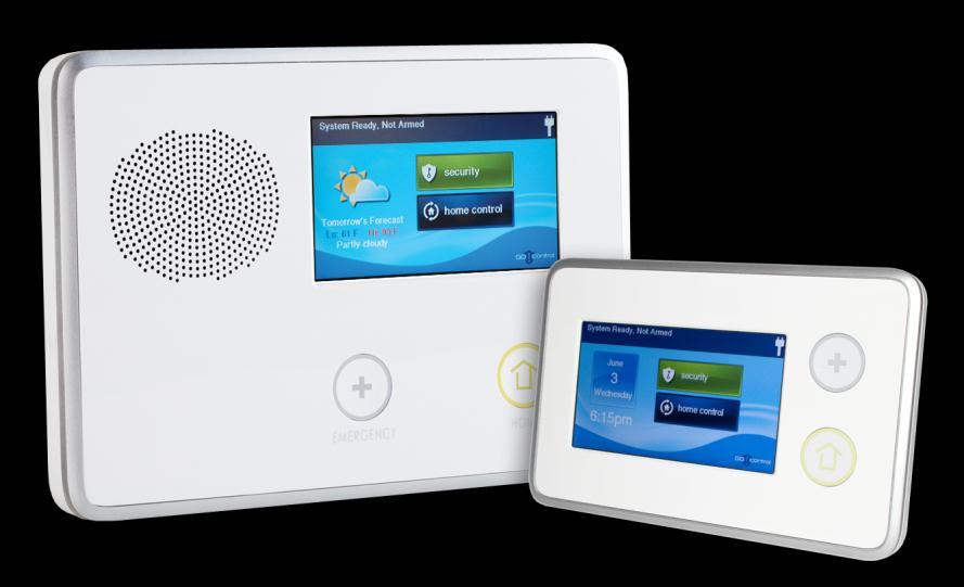

1 Go!Control Installation and Programming Technical Training
2 HARDWARE System Capabilities What s Inside The Transformer Terminal Block GSM Unit

 2-Way Over POTS (optional)")
3 SYSTEM CAPABILITIES 48 Wireless Zones 2 Hardwired Zones 8 Keyfobs 4 Secondary Keypads 2-Way Over GSM (default) 2-Way Over POTS (optional) 232 Z-Wave devices
 24 HR Back-Up Battery")

4 HARDWARE WHAT S IN THE PANEL Third Hand RJ45 Connector (POTS) 24 HR Back-Up Battery 345Mhz Receiver Terminal Block GSM Antenna Compartment Pop-In Style GSM Unit 85dB Siren/Speaker
 Wire to port 1 (+)")
 Wire to port 2 (-) inside")
5 HARDWARE THE TRANSFORMER VDC Positive (+) Wire to port 1 (+) inside the panel VDC Negative (-) Wire to port 2 (-) inside the panel
 5) External Bell (+) (6-12 VDC @ 120mA max) 4) Open Collector")
 1) 14VDC Input (+) from Transformer")
6 HARDWARE TERMINAL BLOCK 8) Hardwire Zone 2 7) Hardwire Zone 1 6) External Bell (-) 5) External Bell (+) ( mA max) 4) Open Collector Output max) 3) Ground (hardwire zones) 2) 14VDC Input (-) from Transformer negative (-) 1) 14VDC Input (+) from Transformer positive (+)


7 HARDWARE GSM MODULE Antenna Port Mounting Screws IMEI# (Serial Number)
8 PROGRAMMING Installer Toolbox System Configuration Programming a Zone Programming a Keyfob Programming a Keypad Radio Status System Restore Walk Test Disable Sounder
9 PROGRAMMING INSTALLER TOOLBOX Press SECURITY

10 PROGRAMMING INSTALLER TOOLBOX Press MENU

11 PROGRAMMING INSTALLER TOOLBOX Press TOOLBOX

12 PROGRAMMING INSTALLER TOOLBOX Press RIGHT ARROW
13 PROGRAMMING INSTALLER TOOLBOX Press RIGHT ARROW

14 PROGRAMMING INSTALLER TOOLBOX Press INSTALLER TOOLBOX

15 PROGRAMMING INSTALLER TOOLBOX Installer Code (1561)
16 PROGRAMMING INSTALLER TOOLBOX Press SYSTEM CONFIGURATION
17 PROGRAMMING SYSTEM CONFIGURATION NAVIGATION Navigated by Questions rather than Field Values Q1: Wireless Zones Q2: Hardwire Zones Q3: Keyfobs Q4: Wireless Keypads Q5-Q86: System Settings Press GO TO followed by the twodigit Question (01-86)
18 PROGRAMMING SYSTEM CONFIGURATION Q1 Q4 Use the and arrows to move back and forth between SUB-QUESTIONS Use the and arrows to scroll through the different options
19 PROGRAMMING SYSTEM CONFIGURATION Q5 Q86 Use the and arrows to move back and forth between QUESTIONS Use the and arrows to scroll through the different options
20 PROGRAMMING Q1: RF SENSORS Select RF Sensor # (01-48) Up to 48 wireless RF sensors can be used with each Control Panel. The options for each sensor are programmed with sub-questions. Begin by entering the RF sensor number or select it using the or arrows. After selecting the sensor number, program the sensor details by using the and arrows to select each of the suboptions. Press the arrow to continue
21 PROGRAMMING Q1: RF SENSORS Select RF Sensor (#) Type Default: Unused (00) Each RF sensor needs to be assigned to a sensor type. The sensor type determines how and when the Control Panel responds to signals from the sensor. Select the sensor type that matches the sensor s function using the or arrows, or enter the sensor type number directly on the keypad.
22 PROGRAMMING Q1: RF SENSORS Select RF Sensor (#) Type Default: Unused (00) SENSOR TYPES (00) unused (01) exit/entry 1 (02) exit/entry 2 (03) perimeter (04) interior follower (05) day zone (06) 24-hour silent alarm (07) 24-hour audible alarm (08) 24-hour auxiliary alarm (09) 24-hour fire (10) interior with delay (14) 24-hour carbon monoxide (16) 24-hour fire with verification (23) no response type (24) silent burglary Press the arrow to continue
23 PROGRAMMING Q1: RF SENSORS Select RF Sensor (#) Equipment Code Default: (0000) Other The equipment code is a 4-digit code that is assigned to the model of sensor being used. The Control Panel will display a list of sensor models and their associated 4-digit equipment code. Select the model of RF sensor being programmed for this sensor number using the or arrows, or enter the equipment code number directly on the keypad.
24 PROGRAMMING Q1: RF SENSORS Select RF Sensor (#) Equipment Code SENSOR EQUIPMENT CODES (0000) other (0862) DW thin door/window contact (0863) DW20R-345 recessed door contact (0869) PIR1-345 PIR with pet immunity (0864) GB1-345 glass break detector (0895) SMKT2-345 GE smoke/heat detector (USA/Canada) (1058) SMKT gig smoke detector (0872) SMKE1-345 smoke detector (USA) (0871) SMKE1-345C smoke detector (Canada) (0868) PANIC1-345 panic button remote (0860) CO1-345 CO detector (USA) (0859) CO1-345C CO detector (Canada) (1026) CO gig CO detector (USA/Canada) (0873) TAKE-345 takeover module (0637) HW D/W 5816 (0470) HW R-D/W 5818MNL (0533) HW PIR 5890 (0530) HW PIR 5894PI (0519) HW Glass Break 5853 (0589) HW Smoke 5808W3 (0557) HW Heat Sensor 5809 (0624) HW Flood Sensor 5821 (0491) HW Panic Pendant 5802MN2 (0655) Existing door/window contact (0609) Existing motion detector (0475) Existing glass break detector (0616) Existing smoke detector (0692) Existing CO detector (0708) Existing heat sensor (0556) Existing flood/temp sensor (1061) GARAGE01 Resolution Products tilt sensor Press the arrow to continue
25 PROGRAMMING Q1: RF SENSORS Select RF Sensor (#) Serial # Default: ( ) RF sensor serial #s can be manually entered or learned from the sensor. For manual entry, enter the sensor number that was logged for the sensor being programmed. Use the SHIFT button to access alpha characters. For automatic entry, press SHIFT, then press LEARN. The Control Panel will wait for a sensor transmission. Trigger the sensor being programmed and the Control Panel will beep four times and learn the sensor s serial number. Press the arrow to continue
26 PROGRAMMING Q1: RF SENSORS Select RF Sensor (#) Equipment Age Default: New (0) The Control Panel can be used with new or existing RF sensors. If this RF sensor is new for the installation, leave the default of new (0). If this RF sensor is already installed, select existing (1). Press the arrow to continue
27 PROGRAMMING Q1: RF SENSORS Select RF Sensor (#) Loop Number Default: (1) 2GIG-DW10 door/window sensors have two inputs. Either or both sensor inputs can be used. LOOP 1 An external normally closed hardwired input LOOP 2 An internal magnetic contact Press the arrow to continue
28 PROGRAMMING Q1: RF SENSORS Select RF Sensor (#) Dialer Delay Default: Enabled (1) RF sensors can trigger the communicator immediately or after a delay. The delay time is set by the abort window dialer delay programming question Q-35 (the default delay is 30 seconds). The default (1) causes delayed dialing for this RF sensor number. For immediate dialing for this RF sensor number, select disabled (0). NOTE: This default can be changed without affecting SIA CP01 compliance. Press the arrow to continue
29 PROGRAMMING Q1: RF SENSORS Select RF Sensor (#) Voice Descriptor The voice descriptors are the words the Control Panel will announce for this RF sensor if this sensor is programmed for voice annunciation. Press INSERT to place a word from the vocabulary into the data entry field. Use the or arrows to scroll through the words, or enter the word s 3-digit index number (see vocabulary table on Page 19). Press INSERT again for the next word. Up to five words are allowed. To move between words, press the FWD and BACK buttons. To remove a word, press DELETE. Press the arrow to continue
30 PROGRAMMING Q1: RF SENSORS Select RF Sensor (#) Reports Default: Enabled (1) RF sensors can trigger a report to the Central Station or not. The default (1) enables reporting for this RF sensor number. To prevent reporting for this RF sensor number, select disabled (0). Press the arrow to continue
31 PROGRAMMING Q1: RF SENSORS Select RF Sensor (#) Supervised Default: Enabled (1) When a sensor is set to supervised, the Control Panel will expect regular timed signals from this sensor or else a sensor supervisory trouble alert will occur. The default (1) allows supervision for this RF sensor. To turn off supervision for this RF sensor, select disabled (0). NOTE: Portable sensors such as panic buttons should not be set as supervised if the sensor will be removed from the premises at times. Press the arrow to continue
32 PROGRAMMING Q1: RF SENSORS Select RF Sensor (#) Chime Default: Disabled (0) Each RF sensor can be set to sound a ding-dong chime and/or sound its voice descriptor when the sensor is triggered. The default (0) disables the chime for this RF sensor. If a chime and/or voice is required for this RF sensor, choose one of the other chime options: RF SENSOR CHIME (0) disabled (1) voice only (2) voice with ding-dong #1 (3) ding-dong #2 (4) voice with ding-dong #2 (5) ding-dong #1 Press the arrow to continue
33 PROGRAMMING Q1: RF SENSORS Summary of RF Sensor (#) The summary page allows you to quickly look over the different settings you chose for that zone and make sure everything is correct. If you need to adjust a setting, press EDIT CURRENT. If everything looks correct, you can press EDIT NEXT to move onto the next zone Press SKIP to move onto the next Question (WIRED ZONES.) Press SKIP to continue
34 PROGRAMMING Q2: WIRED SENSORS Select Wired Sensor # (1 to 2) The Control Panel can be programmed with up to two wired sensors. The wired sensors are hardwired contact loops connected to the loop input terminals on the Control Panel s terminal strip. WIRED SENSOR REPORTING CODES Wired sensor #1 Reports as sensor #49 Wired sensor #2 Reports as sensor #50 NOTE: Wired sensors CANNOT be used for a CO or Fire Sensor loop Press the arrow to continue
35 PROGRAMMING Q2: WIRED SENSORS Select Wired Sensor (#) Type Default: Unused (00) Select the sensor type that matches the wired sensor s function using the or arrows or enter the sensor type number directly on the keypad. SENSOR TYPES (00) unused (01) exit/entry 1 (02) exit/entry 2 (03) perimeter (04) interior follower (05) day zone (06) 24-hour silent alarm (07) 24-hour audible alarm (08) 24-hour auxiliary alarm (10) interior with delay (23) no response type (24) silent burglary Press the arrow to continue
36 PROGRAMMING Q2: WIRED SENSORS Select Wired Sensor (#) Equipment Code Default: (0) The wired sensor equipment code defines the sensor s manufacturer and type. Enter the 4-digit equipment code for the sensor Press the arrow to continue
37 PROGRAMMING Q2: WIRED SENSORS Select Wired Sensor (#) Equipment Age Default: New (0) The Control Panel can be used with new or existing wired sensors. If this wired sensor is new for the installation, leave the default of new (0). If this wired sensor is already installed, select existing (1). Press the arrow to continue
38 PROGRAMMING Q2: WIRED SENSORS Select Wired Sensor (#) Normal State Default: Not Used (0) The two hardwired loops can be wired for normally open (N/O) or normally closed (N/C) contacts, or for end-of-line (EOL) resistor. WIRED SENSOR NORMAL STATE (0) not used (1) closed (2) open (3) end-of-line resistor Press the arrow to continue
39 PROGRAMMING Q2: WIRED SENSORS Select Wired Sensor (#) Dialer Delay Default: Enabled (1) Wired sensors can trigger the communicator immediately or after a delay. The delay time is set by the abort window dialer delay programming question Q-35 (the default delay is 30 seconds). The default (1) causes delayed dialing for this wired sensor number. For immediate dialing for this wired sensor number, select disabled (0). NOTE: This default can be changed without affecting SIA CP01 compliance. Press the arrow to continue
40 PROGRAMMING Q2: WIRED SENSORS Select Wired Sensor (#) Voice Descriptor The voice descriptors are the words the Control Panel will announce for this wired sensor if this sensor is programmed for voice annunciation. Press INSERT to place a word from the vocabulary into the data entry field. Use the or arrows to scroll through the words, or enter the word s 3-digit index number (see vocabulary table on Page 19). Press INSERT again for the next word. Up to five words are allowed. To move between words, press the FWD and BACK buttons. To remove a word, press DELETE. Press the arrow to continue
41 PROGRAMMING Q2: WIRED SENSORS Select Wired Sensor (#) Reports Default: Enabled (1) Wired sensors can trigger a report to the Central Station or not. The default (1) enables reporting for this wired sensor number. To prevent reporting for this wired sensor number, select disabled (0). Press the arrow to continue
42 PROGRAMMING Q2: WIRED SENSORS Select Wired Sensor (#) Chime Default: Disabled (0) Each wired sensor can be set to sound a ding-dong chime and/or sound its voice descriptor when the sensor is triggered. The default (0) disables the chime for this wired sensor. If a chime and/or voice is required for this wired sensor, choose one of the other chime options: WIRED SENSOR CHIME (0) disabled (1) voice only (2) voice with ding-dong #1 (3) ding-dong #2 (4) voice with ding-dong #2 (5) ding-dong #1 Press the arrow to continue
43 PROGRAMMING Q2: WIRED SENSORS Summary of Wired Sensor (#) The summary page allows you to quickly look over the different settings you chose for that zone and make sure everything is correct. If you need to adjust a setting, press EDIT CURRENT. If everything looks correct, you can press EDIT NEXT to move onto the next zone Press SKIP to move onto the next Question. (KEYFOBS) Press SKIP to continue
44 PROGRAMMING Q3: KEYFOBS Select Fob # (1 8) The Control Panel can be programmed with up to eight RF remote control key fobs. RF KEY FOB REPORTING CODES RF key fob #1 Reports as sensor #51 RF key fob #2 Reports as sensor #52 RF key fob #3 Reports as sensor #53 RF key fob #4 Reports as sensor #54 RF key fob #5 Reports as sensor #55 RF key fob #6 Reports as sensor #56 RF key fob #7 Reports as sensor #57 RF key fob #8 Reports as sensor #58 Press the arrow to continue
45 PROGRAMMING Q3: KEYFOBS Select Fob (#) Used Default: Unused (0) Key fobs can be used with the Control Panel or not. The default (0) sets all key fobs as unused (0). To enable programming for this key fob, select used (1). Press the arrow to continue
46 PROGRAMMING Q3: KEYFOBS Select Fob (#) Equipment Code Default: (0000) Other The key fob equipment code defines the sensor s manufacturer and type. The default is (0000) other. Select (0866) KEY button keyfob remote for a 2GIG-KEY1 key fob remote. Select (0577) Existing keyfob remote for an existing key fob remote. NOTE: Only 2GIG-KEY1 key fobs can be used with this system. Press the arrow to continue
47 PROGRAMMING Q3: KEYFOBS Select Fob (#) Serial Number Default: Key fob serial numbers can be manually entered or learned from the fob. For manual entry, enter the fob number that was logged for the fob being programmed. Use the SHIFT button to access alpha characters. For automatic entry, press SHIFT, then press LEARN. The Control Panel will wait for a fob transmission. Trigger the fob being programmed and the Control Panel will learn the fob s serial number. Press the arrow to continue

")
48 PROGRAMMING Q3: KEYFOBS Select Fob (#) Emergency Key Default: Disabled (0) Pressing the AWAY and DISARM buttons on a key fob at the same time for five seconds can trigger an emergency alarm. The default (0) disables the emergency function for this fob. To enable the emergency function for this fob, select one of the four options: FOB EMERGENCY KEY FUNCTION (0) disabled (1) auxiliary alarm (2) audible alarm (3) silent panic (4) fire Press the arrow to continue
49 PROGRAMMING Q3: KEYFOBS Select Fob (#) Key 2 Can Disarm Default: Enabled (1) Key fobs can be set to allow disarming the Control Panel with the fob s DISARM button or not. If using a key fob as a stationary wall fob, it can be set to prevent someone from using it to disarm the system. The default (1) allows this fob to disarm the system. To not allow this fob to disarm the system, select disabled (0). Press the arrow to continue
50 PROGRAMMING Q3: KEYFOBS Select Fob (#) Voice Descriptor Default: Keyfob (#) The voice descriptors are the words the Control Panel will announce for this keyfob sensor for low battery announcements and log entries. Press INSERT to place a word from the vocabulary into the data entry field. Use the or arrows to scroll through the words, or enter the word s 3-digit index number. Press INSERT again for the next word. Up to five words are allowed. To move between words, press the FWD and BACK buttons. To remove a word, press DELETE. Press the arrow to continue
51 PROGRAMMING Q3: KEYFOBS Select Fob (#) Arm No Delay (Instant) Default: Disabled (0) Key fobs can be set to arm the Control Panel with or without an Entry Delay. The default (0) sets this fob to arm the system with an Entry Delay. To set this fob to arm the system without an Entry Delay, select enabled (1). Press the arrow to continue
52 PROGRAMMING Q3: KEYFOBS Select Fob (#) Key 4 Output Default: Disabled (0) The key fob s AUXILARY (*) button can be used to trigger the Control Panel s open collector output. The default (0) disables this fob s auxiliary button. To use this fob s auxiliary button, select the output function. FOB KEY 4 OUTPUT (0) disabled (1) toggle output (2) momentary output Press the arrow to continue
53 PROGRAMMING Q3: KEYFOBS Summary of Fob (#) The summary page allows you to quickly look over the different settings you chose for that keyfob and make sure everything is correct. If you need to adjust a setting, press EDIT CURRENT. If everything looks correct, you can press EDIT NEXT to move onto the next keyfob. Press SKIP to move onto the next Question (KEYPADS.) Press SKIP to continue
54 PROGRAMMING Q4: KEYPADS Select RF Keypad # (1 4) The Control Panel can be programmed with up to four RF remote control keypads or wireless touch screen keypads. RF KEYPAD REPORTING CODES RF Keypad #1 Reports as sensor #59 RF Keypad #2 Reports as sensor #60 RF Keypad #3 Reports as sensor #61 RF Keypad #4 Reports as sensor #62 Press the arrow to continue
55 PROGRAMMING Q4: KEYPADS Select RF Keypad (#) Used Default: Unused (0) Keypads can be used with the Control Panel or not. The default (0) sets all keypads as unused (0). To enable programming for this keypad, select used (1). Press the arrow to continue
56 PROGRAMMING Q4: KEYPADS Select RF Keypad (#) Equipment Code Default: (0000) Other The RF keypad equipment code defines the sensor s manufacturer and type. Select (0867) PAD1-345 wireless keypad for a 2GIG-PAD1 RF keypad. Select (1059) TS-1 wireless touchscreen keypad for a 2GIG-TS1 Wireless Touch Screen Keypad. NOTE: The TS-1 wireless keypad is not for UL985 installations. Press the arrow to continue
57 PROGRAMMING Q4: KEYPADS Select RF Keypad (#) Serial Number Default: Keypad serial numbers can be manually entered or learned from the fob. For manual entry, enter the keypad number that was logged for the fob being programmed. Use the SHIFT button to access alpha characters. For automatic entry, press SHIFT, then press LEARN. The Control Panel will wait for a keypad transmission. Trigger the keypad being programmed and the Control Panel will learn the keypad s serial number. Press the arrow to continue

58 PROGRAMMING Q4: KEYPADS Select RF Keypad (#) Serial Number Default: For 2GIG-TS1 Wireless Touch Screen Keypads press LEARN. The Control Panel will display Pair with TS-1. Initiating learning process. Press the TS1 keypad s PAIR WITH PANEL button. Both the TS1 and the Control Panel will display The learn operation succeeded when complete. The Control Panel will display RF keypad (#1-4) for keypad identification. The TS1 will display Network ID: xxxx which is the unique serial number identifying the specific keypad. Press OK on both the Control Panel and TS1 to continue. NOTE: The Model 2GIG-TS1 wireless touch screen keypad will display The security system is temporarily not operational after learning the keypad. This is normal, and will be displayed anytime the Control Panel is in system configuration (programming) mode. Press the arrow to continue

59 PROGRAMMING Q4: KEYPADS Summary of RF Keypad (#) The summary page allows you to quickly look over the different settings you chose for that keypad and make sure everything is correct. If you need to adjust a setting, press EDIT CURRENT. If everything looks correct, you can press EDIT NEXT to move onto the next keypad. Press SKIP to move onto the next Question (SETTINGS) Press SKIP to continue
60 IMPORTANT QUESTIONS Q:8 Dialer (default 0) If the system you are installing is POTS primary or GSM back-up, you must enable Q:8 so the system will look for a POTS line. Q:11 Enter CS Phone # (no default) Here is where you would enter the Central Station Receiver line. Remember to check for prefixes that might be required to dial out (Q:9). Only necessary for POTS systems. Q:12 CS Account # (no default) Here is where you would enter the last 4 digits of your Central Station account #. Only necessary for POTS systems. Q:63 Phone Fail Detect (default 0) Again, if the system you are installing is POTS primary or GSM back-up, you must enable Q:63 so the system will look for a POTS line and then send a trouble signal if the line is lost.
61 IMPORTANT QUESTIONS Q:43 Enter Installer Code (1561) Here is where you can change your installer code. Q:44 Lock Installer Programming (default 0) The installer programming lockout feature is provided to prevent takeovers. The Control Panel can be set To limit an installer s access to programming questions after a period of 48 hrs. The 48 hr lockout timer Starts when the installer exits system configuration. 0 unlimited full access (default) 1 deny access to programming after 48 hrs 2 limited access to programming after 48 hrs. Installer can view, but not change CS phone # or or account #, or change installer lock settings. Q:79 Select Z-Wave feature (default 1) Here is where you can enable Z-Wave and remote access settings.

62 INSTALLER TOOLBOX RADIO STATUS The radio status option allows you to monitor your cell strength, the activity of the cell unit, its serial number, and other information. You can also run a cell phone test manually to check to make sure it is linked correctly to your Central Station.

63 INSTALLER TOOLBOX RESTORING DEFAULTS You can choose to restore the system to its original default settings, or reset only the console or zones individually.

64 INSTALLER TOOLBOX WALK TEST The Walk Test (Installer Toolbox) and System Test (Customer Toolbox) are identical. This will enable you, or the customer to trip the sensors to test the signal strength of the equipment and to make sure the components are installed correctly. This will not send a signal to your Central Station.

65 INSTALLER TOOLBOX DISABLE SOUNDER By pressing ok, you will disable the sounder (siren) for 30 min. After that, It will automatically enable itself. Or you can manually enable the sounder with the same menu option.
66 TAKEOVER MODULE SUPER SWITCH Convert 8 hardwire zones into 8 wireless zones by utilizing the existing hardwire system. Stack up to 6 Takeover Modules onto 1 GO!CONTROL system. Take over dry contacts as well as powered zones.

67 TAKEOVER MODULE SUPER SWITCH G PORT Common ground port LO wires from the existing system 12V PORT 12 VDC power from the existing systems AUX power ZONE PORTS HI wires from existing system
 Connect back-up battery terminals (module and existing system) 4)")

68 TAKEOVER MODULE WIRING 12V BATT *Wiring order: 1) Disconnect all power to existing hardwire system 2) Completely wire the takeover module 3) Connect back-up battery terminals (module and existing system) 4) Reconnect the existing systems power supply DC (AUX) POWER LO WIRES HI WIRES EXISTING SYSTEMS AC POWER *If not powered up in correct order, The system will show a low battery On each zone controlled by the Takeover module.
69 TAKEOVER MODULE PROGRAMMING Type: Equipment: Serial#: Age: Loop: Dialer Delay: Voice Descriptor: Reports: Supervised: Chime: entry/exit, perimeter, etc 0873 TAKE-345 XXX-XXX1 for each zone after, add 1 to the last digit 1 st zone new each zone after - existing 1 (always) disabled (unless required) program accordingly enabled enabled (customer) XXX-XXX2 XXX-XXX1 XXX-XXX3


70 HOME SERVICES WHAT IS Z-WAVE? SYSTEM CONFIGURATION ADDING A Z-WAVE DEVICE CREATING SCENES CREATING RULES Z-STAT (CT30)


71 HOME SERVICES WHAT IS Z-WAVE? Z-Wave is a next-generation wireless ecosystem that lets all your home electronics talk to each other, and to you, via remote control. It uses simple, reliable, low-power radio waves that easily travel through walls, floors and cabinets. Z-Wave control can be added to almost any electronic device in your house, even devices that you wouldn't ordinarily think of as "intelligent," such as appliances, window shades, thermostats and home lighting. Z-Wave Is Simple Z-Wave control is easily added to almost any device in minutes. Simply plug the device you want to control into a Z-Wave module, and "join" it to your Z-Wave network! Z-Wave Is Modular With Z-Wave, you can add as much or as little home control as you want over time. You can add Z-Wave to a device, a room, a floor or the entire home, according to your needs and desires. Z-Wave Is Affordable Unlike costly whole-home control systems that need special wiring and professional installation, Z-Wave is accessible and easy for the do-it-yourselfer Z-Wave Is Powerful Z-Wave's intelligent mesh networking 'understands" the present status of any enabled device, and gives you confirmation that your devices have received the automatic or manual control commands you want Z-Wave Is Versatile Z-Wave can be added to almost anything in your home that uses electricity, and gives you the power to control or monitor them from your home or away from home. Z-Wave Is Intelligent Z-Wave enabled devices can work together as a team. Have your garage door turn on your house lights when you come home. Have your door locks notify you when your children arrive home from school. Turn your downstairs lights off from upstairs. Create your own intelligent control "scenes" with Z-Wave!

72 Z-Wave Z-Wave is a WIRELESS COMMUNICATION PROTOCOL using the MHz frequency. Simple, energy efficient, two-way communication Easily control lights, thermostats, locks, etc. Uses mesh network topology for increased network robustness and range Used by over 200 companies to make a wide variety of products.
 will relay the signal to the out of range device.")
73 Z-Wave & the Install Most Z-Wave devices have a lineof-sight range of feet. Unfortunately, homes have walls, appliances, or other things that can interfere with the signal. Using another Z-Wave device that repeats (like an Evolve lamp module) will relay the signal to the out of range device. The more devices you add to your network, the more reliable your network becomes.

74 HOME SERVICES PROGRAMMING Questions in System configuration are required to be modified for The Home Services portion of the Go!Control panel to function. Below are the questions and their options.
75 HOME SERVICES PROGRAMMING Q79 SELECT Z-WAVE FEATURE Defaulted as (1) Disabled, Visible (0) Disabled (the Home Services button is hidden globally) (1) Disabled, Visible (The Home Services button is visible and when user presses the Home Services button the panel will read: The Home Services feature is not currently activated. To activate Home Services, please call your security provider. (2) Local fully enabled, remote access disabled (3) Local partially enabled, local rules disabled, remote control enabled
 Disabled (0) Disabled (1) Enabled")
76 HOME SERVICES PROGRAMMING Q80 SELECT Z-WAVE SWITCH CONTROL FEATURE Defaulted as (0) Disabled (0) Disabled (1) Enabled
77 HOME SERVICES PROGRAMMING Q81 SELECT Z-WAVE THERMOSTAT CONTROL FEATURE Defaulted as (0) Disabled (0) Disabled (1) Enabled
78 HOME SERVICES PROGRAMMING Q82 SELECT Z-WAVE DOOR LOCK CONTROL FEATURE Defaulted as (0) Disabled (0) Disabled (1) Enabled
79 HOME SERVICES ADDING & REMOVING DEVICES Press SERVICES
80 HOME SERVICES ADDING & REMOVING DEVICES Press TOOLBOX
81 HOME SERVICES ADDING & REMOVING DEVICES Enter INSTALLER CODE
82 HOME SERVICES ADDING & REMOVING DEVICES Press ADD/REMOVE DEVICES

83 HOME SERVICES ADDING & REMOVING DEVICES
84 HOME SERVICES ADDING & REMOVING DEVICES DISCOVERY SCREEN: PRESS AND RELEASE DEVICE BINDING SWITCH WHEN A DEVICE IS DISCOVERED, IT WILL SHOW THE MANUFACTURER AND THE NODE #

85 HOME SERVICES ADDING & REMOVING DEVICES DISCOVERY SCREEN: PRESS AND RELEASE DEVICE BINDING SWITCH WHEN A DEVICE IS REMOVED IT WILL SHOW THAT IT HAS BEEN REMOVED
86 HOME SERVICES RENAMING A DEVICE Press SWITCHES

87 HOME SERVICES RENAMING A DEVICE Press DEVICE BAR

88 HOME SERVICES RENAMING A DEVICE Press RENAME
89 HOME SERVICES RENAMING A DEVICE KEYBOARD: USE THE KEYBOARD TO CUSTOM NAME THE DEVICE

90 HOME SERVICES RENAMING A DEVICE KEYBOARD: USE THE KEYBOARD TO CUSTOM NAME THE DEVICE NOW THE STATUS SCREEN WILL SHOW THE DEVICE NAME RATHER THAN THE MANUFACTURER
91 HOME SERVICES CREATING A SCENE Press SCENES

92 HOME SERVICES CREATING A SCENE Press ADD SCENE
93 HOME SERVICES CREATING A SCENE Name the Scene
94 HOME SERVICES CREATING A SCENE Press ADD ACTION

95 HOME SERVICES CREATING A SCENE Select a Device Type

96 HOME SERVICES CREATING A SCENE Select The Action Press OK

97 HOME SERVICES CREATING A SCENE List of Scenes

98 HOME SERVICES CREATING A RULE Press RULES
99 HOME SERVICES CREATING A RULE Press ADD RULES

100 HOME SERVICES CREATING A RULE Select the EVENT Select the SCENE

101 HOME SERVICES CREATING A RULE List of Rules

102 HOME SERVICES CREATING A RULE ON ALARM.COM
103 THERMOSTAT CT-30e WHY DO WE OFFER ONE? INSTALLATION STEPS NETWORK INCLUSION
104 THERMOSTAT CT-30e The Z-Stat (CT-30e) Manufactured by Radio Thermostat Co Flawless integration with the CNTRL2 Panel Touch Screen Interface 10 month battery life Also has a C wire for powered applications
105 THERMOSTAT WIRING Step 1 Cut all power to the HVAC system (turn off the breaker) Step 2 LABEL! LABEL! LABEL! There isn t any wire color code with HVAC systems, so it is vital that you label the wires as you remove them from the existing thermostat. Step 3 Install your new 2GIG-Z-Stat by lining up your labeled wires with the ports. If some of your labeled wires do not correspond with any ports on the thermostat, see your installation guide for alternative labeling (p ) Step 4 Power up the HVAC system. A good way to test if the thermostat is working is to manually turn on the fan. You will hear the fan kick on. USE THE INSTALLATION GUIDE INCLUDED WITH THE THERMOSTAT TO IDENTIFY WHAT TYPE OF HVAC SYSTEM YOU ARE WORKING WITH SO YOU CAN SET UP THE THERMOSTAT CORRECTLY.
106 THERMOSTAT NETWORK INCLUSION Step 1 Make sure Questions 79 and 81 are enabled Step 2 Now, go to ADD DEVICES and link the thermostat. Press the MENU button on the right, then the MATE touch screen button on the left twice. Wait for the ADD DEVICES page to upload all the information from the thermostat, this may take a little bit (30 sec or so).

107 THERMOSTAT NETWORK INCLUSION Step 1 Make sure Questions 79 and 81 are enabled Step 2 Now, go to ADD DEVICES and link the thermostat. Press the MENU button on the right, then the MATE touch screen button on the left twice. Wait for the ADD DEVICES page to upload all the information from the thermostat, this may take a little bit (30 sec or so).
108 THERMOSTAT NETWORK DISCOVERY Step 3 Allow device to fully query and upload Step 4 Add to scenes or rules
109 2GIG Technical Support 855.2GIGTEC HRS of Operation Mon Fri: 8am 7pm (MST) Sat: 8am 4pm (MST) Alarm.com Tech Support 9am 7pm (EST M-F) Radio Thermostat Tech Support 9am 12am (EST 7 days/week) support@radiothermostat.com
110 Andrew Curtis Director of Customer Support o: c:
Testing the System. Battery Test. Dialer Test. Fire Drill Test (Code + [#] + 69) One-Man Fire Walk-Test (Code + [#] + 68)
![Testing the System. Battery Test. Dialer Test. Fire Drill Test (Code + [#] + 69) One-Man Fire Walk-Test (Code + [#] + 68)](/thumbs/79/79864325.jpg "Testing the System. Battery Test. Dialer Test. Fire Drill Test (Code + [#] + 69) One-Man Fire Walk-Test (Code + [#] + 68)") F A 1 7 0 0 c Testing the System Battery Test When AC power is present, the FA1700C runs a brief battery test every 60 seconds to determine if there is a battery connected, and runs an extended battery
F A 1 7 0 0 c Testing the System Battery Test When AC power is present, the FA1700C runs a brief battery test every 60 seconds to determine if there is a battery connected, and runs an extended battery
RE6100 Series Helix Security and Automation Platform
 CONFIGURATION Resolution Compatibles RE6100 Series Helix Security and Automation Platform C G UI D E Configuration Settings Table 1 - Panel Settings Table 2 - Zone Settings Table 3 - Device Settings Table
Wireless Security System
 Wireless Security System 2GIG-CNTRL2 Operation & User s Guide WARNING: Owner s Instruction Notice Not to be removed by anyone except occupant Technical Support 866-670-1591 www.2gig.com The GO!control
All-In-One Wireless Security System V3.2 Programming Guide. Model # MG6130 / MG6160
 All-In-One Wireless Security System V3.2 Programming Guide Model # MG6130 / MG6160 We hope this product performs to your complete satisfaction. Should you have any questions or comments, please visit www.paradox.com
LyricTM. Programming Guide. Controller. Ref: LCP500-L/LCP500-LC V1 11/15 Rev A
 LyricTM Controller Programming Guide Ref: LCP500-L/LCP500-LC 800-18077V1 11/15 Rev A RECOMMENDATIONS FOR PROPER PROTECTION The Following Recommendations for the Location of Fire and Burglary Detection
Installation Instructions
 NX-148E-RF LCD Touchpad with Receiver 466-2198C February 2006 Copyright 2006, GE Security Inc. Contents Product summary 1 Installation 1 Transmitter programming 2 Touchpad programming 5 Reference tables
Honeywell Control Panels FOR RESIDENTIAL AND COMMERCIAL INSTALLATIONS. Feature Charts
 Honeywell Control Panels FOR RESIDENTIAL AND COMMERCIAL INSTALLATIONS Feature Charts Control Panels FEATURE CHART LYNX Plus (L3000) (Supported Feature) (Not Supported) N/A (Not Applicable) LYNX Touch (L5210)
USER'S GUIDE FA1220CV. 2-Partition Security System N7003-1V2 7/98
 USER'S GUIDE FA1220CV 2-Partition Security System N7003-1V2 7/98 SYSTEM OVERVIEW... 3 General... 3 A Partitioned System... 3 Zones... 3 Burglary Protection... 4 Fire Protection... 4 Alarms... 5 Emergency
EVO192 v3.0 Fire and Burglary What s New
 EVO192 v3.0 Fire and Burglary What s New Compatibility: EVO192 v3.0 TM50 v1.31 K641 v2.41 Overview: CP-01 Compliancy Wiring Diagram The following sections/options have been added to the EVO192 panel. They
User s Guide. SUB-MA7240O-0001.OG.Solution doc. Created: 6/05/03. Last Updated: 23/09/03. MA7240AO-0001 Version 1.0
 User s Guide SUB-MA7240O-0001.OG.Solution40-111.doc Created: 6/05/03 Last Updated: 23/09/03 MA7240AO-0001 Version 1.0 2 Table Of Contents User List...6 Quick Reference..7 Features...7 Keypad User's Guide...8
Supervised Security System Owner's Guide
 Owner's Guide PSC06 READ THIS FIRST This equipment generates and uses radio frequency energy, and if not installed and used properly, that is, in strict accordance with the manufacturers instructions,
Fire Burglary Instruments Inc. XL-2G Gold Control/Communicator Installation Training Seminar Rev. 5/96
 Fire Burglary Instruments Inc. XL-2G Gold Control/Communicator Installation Training Seminar Rev. 5/96 XL-2G Gold Product Overview 7 Zones (6 programmable + panic or keyswitch zone) Fast Loop Response
$'(0&2 9,67$ 3DUWLWLRQHG 6HFXULW\ 6\VWHP 8VHU *XLGH N7003V3 5/04 Rev A
 $'(0&29,67$ 3DUWLWLRQHG6HFXULW\6\VWHP 8VHU*XLGH N7003V3 5/04 Rev A 2 TABLE OF CONTENTS SYSTEM OVERVIEW...5 General...5 A Partitioned System...5 Zones...5 Fire Protection...6 Burglary Protection...6 Alarms...6
LYNX Touch Security System
 LYNX Touch Security System Programming Guide ARMED READY 800-06895 3/11 Rev. A Table of Contents Entering Programming Mode... 3 Programming the Data Fields... 3 Loading a Default Set... 3 Exiting Programming
VISTA-50P VISTA-50PUL
 Security System User's Manual VISTA-50P VISTA-50PUL N5943-6V1 Rev B 4/99 TABLE OF CONTENTS SYSTEM OVERVIEW...4 General...4 A Partitioned System...4 Zones...4 Fire Protection...5 Burglary Protection...5
ADEMCO LYNX XL SERIES Security System
 ADEMCO LYNX XL SERIES Security System LXL-1010 Installation and Setup Guide BETA DRAFT COPY 8/23/04 K9349-1 8/04 Rev. A RECOMMENDATIONS FOR PROPER PROTECTION The Following Recommendations for the Location
Contents. Glossary
 Contents Glossary ------------------------------------------------------------------------------------------------------ 6 1. Introduction to the IDS 1632 -------------------------------------------------------------
All-In-One Wireless Security System V1.0. Model #: MG Reference and Installation Manual
 All-In-One Wireless Security System V1.0 Model #: MG-6060 Reference and Installation Manual Table of Contents Introduction... 3 About Magellan and this Manual... 3 Conventions... 3 Specifications... 3
Congratulations! This manual consists of four sections: SECTION 1 introduces you to the components of your CareTaker system.
 Congratulations! Your purchase of the CareTaker security system is a decision which will afford you greater peace of mind for the many years of service the system is designed to provide. The CareTaker
DESTINY OWNER S MANUAL
 DESTINY OWNER S MANUAL DESTINY You have made a wise decision to protect your family and property with the DESTINY Security System. The DESTINY has been designed to provide you with a maximum level of security
DSC PowerSeries NEO Quick Start Guide
 DSC PowerSeries NEO Quick Start Guide WE DO NOT RECOMMEND BEING IN ANY PROGRAMMING SECTION THAT IS NOT IN THIS GUIDE UNLESS YOU FULLY UNDERSTAND THE FUNCTION OF THAT SECTION. Doing so may cause problems
ATS1235 Advanced Wireless DGP on 868 MHz AM Installation Sheet
 ATS1235 Advanced Wireless DGP on 868 MHz AM Installation Sheet EN 1 2 1 3 2 4 1 5 12V 6 2 0V D+ D- CON3 7 CON1 ON 3 1 2 3 4 1234 8 3 4 1 0 ON 1 2 3 4 METAL METAL Address 1 1 0 ON 1 2 3 4 Address 2 2011
Security System Proposal
 Security System Proposal Thank you for the opportunity to present this proposal for a complete security and installation for your home. Our family has been selling security systems, home automation and
&RPPHUFLDO)LUHDQG%XUJODU\ 3DUWLWLRQHG6HFXULW\6\VWHP ZLWK6FKHGXOLQJ
LUHDQG%XUJODU\ 3DUWLWLRQHG6HFXULW\6\VWHP ZLWK6FKHGXOLQJ") 9,67$)% &RPPHUFLDO)LUHDQG%XUJODU\ 3DUWLWLRQHG6HFXULW\6\VWHP ZLWK6FKHGXOLQJ 8VHU*XLGH FIRE FIRE * PULL K3522 3/99 TABLE OF CONTENTS SYSTEM OVERVIEW...4 General...4 A Partitioned System...4 Zones...5 Fire
9,67$)% &RPPHUFLDO)LUHDQG%XUJODU\ 3DUWLWLRQHG6HFXULW\6\VWHP ZLWK6FKHGXOLQJ 8VHU*XLGH FIRE FIRE * PULL K3522 3/99 TABLE OF CONTENTS SYSTEM OVERVIEW...4 General...4 A Partitioned System...4 Zones...5 Fire
First Alert 1200C Installer Notes M. Leuck
 First Alert 2C Installer Notes M. Leuck. Programming can done by standard keypads 2. Enter programming with Installer Code + 8 + + 3. Another method of entering programming: Power system down, then back
All-In-One Wireless Security System V1.0. Model #: MG-6060
 All-In-One Wireless Security System V1.0 Model #: MG-6060 Reference and Installation Manual DRAFT Table of Contents Introduction... 5 About Magellan and this Manual... 5 Conventions... 5 Specifications...
PiSector GSM Cellular Wireless Alarm System
 PiSector GSM Cellular Wireless Alarm System User Manual ( GS08 ) Read manual fully before use. PiSector Inc., USA, www.pisector.com Welcome to PiSECTOR Thank you for choosing PiSECTOR. Everyone at PiSECTOR
Wireless Devices. This chapter introduces the suite of DSC wireless sensors and devices used with the Impassa and other series of DSC alarm systems
 Wireless Devices This chapter introduces the suite of DSC wireless sensors and devices used with the Impassa and other series of DSC alarm systems ALARM DETECTORS WS4945 DOOR/WINDOW SENSOR The WS4945 is
icontrol OpenHome Converge Panel Interface Module Installation Guide Congratulations on purchasing your Panel Interface module.
 icontrol OpenHome Converge Panel Interface Module Installation Guide Congratulations on purchasing your Panel Interface module. The icontrol Networks, Inc. OpenHome Converge Panel Interface Module (PIM)
&RPPHUFLDO%XUJODU\ 3DUWLWLRQHG6HFXULW\6\VWHP ZLWK6FKHGXOLQJ
 READY ARMED READY 1 OFF 7 INSTANT READY 2 AWAY 8 CODE 6BYPASS 9 CHIME 9,67$% &RPPHUFLDO%XUJODU\ 3DUWLWLRQHG6HFXULW\6\VWHP ZLWK6FKHGXOLQJ 8VHU*XLGH ARMED READY 1 OFF 2 AWAY 3 STAY 4 MAX 5 TEST 6 BYPASS
Control/Communicator Installation Manual
 DAS NETWORX NX-12 Control/Communicator Installation Manual General Description...2 Ordering Information...2 Option Definitions...3 Programming the LED Code Pads...5 Programming the NX-12...9 Types of Programming
**** **** A B ARMED FIRE FIRE C D READY OFF AWAY STAY 2 3 MAXIMUM TEST BYPASS PULL INSTANT CODE CHIME. First Alert READY. * 0 # Professional
 ARMED READY READY )$&&$&% )LUHDQG%XUJODU\ 3DUWLWLRQHG6HFXULW\6\VWHPV ZLWK6FKHGXOLQJ **** **** A B C D FIRE FIRE First Alert OFF AWAY STAY 2 3 1 4 5 6 7 8 9 MAXIMUM TEST BYPASS INSTANT CODE CHIME * 0 #
Lyric Gateway. User Reference Guide. Ref: LCP300-L/LCP300-LC /16 Rev A
 Lyric Gateway User Reference Guide Ref: LCP300-L/LCP300-LC 800-21670 10/16 Rev A Your Honeywell security system is designed for use with devices manufactured or approved by Honeywell for use with your
Simon XTi Quick Operation Guide
 Simon XTi Quick Operation Guide This is the Quick Operation Guide for the Simon XTi system (models 600-1054-95R-12 & 600-1054-95R-12-CN). The Simon XTi provides a graphical user interface for programming
DESTINY 6100 SERIES SECURITY SYSTEM OWNER S MANUAL V1 12/01
 DESTINY 6100 SERIES SECURITY SYSTEM OWNER S MANUAL 800-6006V1 12/01 System Overview General Information Control Panel Detection Devices You have made a wise decision to protect your family and property
INSTALLATION MANUAL. Qolsys IQ Panel 2 Software Version 2.0
 INSTALLATION MANUAL Qolsys IQ Panel 2 Software Version 2.0 The Qolsys IQ Panel 2 is a 7 touchscreen built with an Android operating system, providing full security and smart home functionality in an easy
abode Web app Functionality
 abode Web app Functionality System mode display controls the state of the alarm system. The user can change the mode of the system by simply clicking on the desired mode. When arming the system with the
/10 Rev A
 VISTA-128BPT/ VISTA-250BPT/ VISTA-128BPTSIA Commercial Burglary Partitioned Security System With Scheduling User Guide 800-06905 6/10 Rev A Your Honeywell security system is designed for use with devices
INSTALLATION MANUAL. Qolsys IQ Panel 2 Software Version 2.0.6
 INSTALLATION MANUAL Qolsys IQ Panel 2 Software Version 2.0.6 The Qolsys IQ Panel 2 is a 7 touchscreen built with an Android operating system, providing full security and smart home functionality in an
P Zone Expandable Hybrid Security System
 Page 1 of 11 up to 8 hardwired keypads and 4 wireless keypads 4 hardwired keypads available with zone input PWLS910 wireless handheld keypad added wireless control is provided by - PWLS908 wireless panic
VISTA-32FBPT. Commercial Fire and Burglary Partitioned Security Systems with Scheduling. User Guide /12 Rev. B
 VISTA-32FBPT Commercial Fire and Burglary Partitioned Security Systems with Scheduling User Guide 800-11045 2/12 Rev. B 2 TABLE OF CONTENTS SYSTEM OVERVIEW...5 General...5 A Partitioned System...5 Zones...6
3 User s settings. 3.3 Internal clock setting
 2.9 Subsystem arming In a large building a sub control panel can be enrolled to the JA-63. The subsystem reports all alarms and failures to the main system. The installer can program if the systems will
HMS MODEL 925 OWNER'S MANUAL
 HMS MODEL 925 OWNER'S MANUAL Document Number 889150 Rev B November, 1999 Copyright 1999 HAI All Rights Reserved OnQ Technologies, Inc. i Contents INTRODUCTION...1 Underwriter's Laboratories (UL) Listing...1
HMS MODEL 800 Owner s Manual
 HMS MODEL 800 Owner s Manual OnQ Document Number 1307535 Rev A October, 2000 Copyright v 2000 HAI All Rights Reserved www.onqtech.com Contents INTRODUCTION... 1 Underwriter's Laboratories (UL) Listing...
/14 Rev. A LYNX Touch L5210 Series
 800-19975 12/14 Rev. A LYNX Touch L5210 Series Your Honeywell security system is designed for use with devices manufactured or approved by Honeywell for use with your security system. Your Honeywell security
M2M Services Ltd. RControl Alarm - Installer Manual V 1.0
 M2M Services Ltd. RControl Alarm - Installer Manual V 1.0 Content Content... 2 Wiring the power supply module... 3 Wiring a siren... 3 SMARTEnroll self-learning zones... 3 Wireless keyfobs... 3 Supported
LYNX Touch L5210 Series Security System
 LYNX Touch L5210 Series Security System User Guide 800-19975 12/14 Rev. B LYNX Touch L5210 Series Your Honeywell security system is designed for use with devices manufactured or approved by Honeywell for
TABLE OF CONTENTS TABLE OF CONTENTS 1
 TABLE OF CONTENTS TABLE OF CONTENTS 1 FEATURES 2 Keypad Programmable... 2 EEPROM Memory... 2 Static/Lightning Protection... 2 Supervision... 2 Operation... 2 SPECIFICATIONS 2 PC1550 Control Panel... 2
User's Manual VISTA-40 N7003V1 6/97
 S e c u r i t y S y s t e m User's Manual VISTA-40 N7003V1 6/97 SYSTEM OVERVIEW...3 General...3 A Partitioned System...3 Zones...3 Burglary Protection...4 Fire Protection...4 Alarms...5 Emergency (Panic)
Safewatch Pro 3000 System Manual
 «Help Center Select System System Arm & Panic Alarms Trouble User Access System Other System Overview Keywords Disarm the Conditions Codes Testing Information System System Overview Overview The Safewatch
INSTALLATION MANUAL. Qolsys IQ Panel 2 Software Version 2.1.0
 INSTALLATION MANUAL Qolsys IQ Panel 2 Software Version 2.1.0 The Qolsys IQ Panel 2 is a 7 touchscreen built with an Android operating system, providing full security and smart home functionality in an
INSTALLATION GUIDE XTLN-WIFI PANEL
 INSTALLATION GUIDE XTLN-WIFI PANEL MODEL XTLN-WiFi INSTALLATION GUIDE FCC NOTICE This equipment has been tested and found to comply with the limits for a Class B digital device, pursuant to part 15 of
Digiplex System V2.14 / V2.2ACC. Control Panel Programming Guide
 Digiplex System V2.14 / V2.2ACC Control Panel Programming Guide Table of Contents Getting Started...2 What Do I Do First?...2 How Do I Program the Control Panel?...2 Single Digit Entry Method...2 Multiple
LYNXR-2 Series Security System
 For Service Call: (866) 401-4842 LYNXR-2 Series Security System User Guide ARMED READY OFF 1 2 3 ESCAPE RECORD VOLUME AWAY 4 5 6 PLAY ADD STAY LIGHTS ON TEST BYPASS 7 8 9 DELETE LIGHTS OFF CODE CHIME AUX
PROGRAMMING GUIDE SPECTRA CONTROL PANELS V , 1725EX, 1728 AND 1728EX 1755, 1755EX, 1758, AND 1758EX
 PROGRAMMING GUIDE SPECTRA CONTROL PANELS V1.2 1725, 1725EX, 1728 AND 1728EX 1755, 1755EX, 1758, AND 1758EX TABLE OF CONTENTS HOW DO I PROGRAM THE SYSTEM?... 4 Single Digit Data Entry Method (Hexadecimal
AdvisorOne Quick Operation Guide
 AdvisorOne Quick Operation Guide EN CNF ES PR English: Quick Operation Guide Introduction AdvisorOne (part # AVO-1037) is a wireless, self-contained system used to detect, control and inform of security
USER GUIDE WIRE-FREE HOME PROTECTION SYSTEM AG100+ CONTENTS
 CONTENTS USER GUIDE WIRE-FREE HOME PROTECTION SYSTEM AG00 Section Getting started. General system overview. Introduction to the system. Items included with the system. Introduction to the Smart Panel.5
LYNX Touch Security System
 LYNX Touch Security System User Guide 1:35 2 PM October 26, 2011 72 Mostly Sunny 68 F F Feels Like 71 Security Messages Automation 5-Day Forecast News Traffic 800-10615 1/12 Rev. A LYNX Touch L5100 Series
Omni LTe WEB VERSION. Owner's Manual. Control & Security System. Includes the SIA CP-01 Control Panel Standard Features for False Alarm Reduction
 Omni LTe Control & Security System Includes the SIA CP-01 Control Panel Standard Features for False Alarm Reduction Owner's Manual WARNINGS AND CAUTIONS Read and understand all instructions. Follow all
CONTENTS. (User s Manual)
") CONTENTS (User s Manual) 1. Foreword & Main Features & Brief introduction of the Product 2. Understanding of Alarm Host 3. Specifications 4. Type and definition of Defense Line 5. Programming the alarm
CONTENTS (User s Manual) 1. Foreword & Main Features & Brief introduction of the Product 2. Understanding of Alarm Host 3. Specifications 4. Type and definition of Defense Line 5. Programming the alarm
NetworX NX-548E Receiver Installation Instructions
 NetworX NX-548E Receiver Installation Instructions Content Introduction... 1 Internal mounting... 1 External mounting... 2 Wiring... 3 DIP switch settings... 3 Power up... 3 Programming... 4 Testing and
SILENCING AN ALARM When the alarm bell or siren is sounding, enter your user code or present your SecuraProx fob to your keypad.
 SYSTEM USER GUIDE SILENCING AN ALARM When the alarm bell or siren is sounding, enter your user code or present your SecuraProx fob to your keypad. IS THIS A FALSE ALARM? YES NO displays. REAL ALARM If
NetworX Series. NX-8 Commercial Fire Panel Installation and Startup
 NetworX Series NX-8 Commercial Fire Panel Installation and Startup 2004 GE Security All rights reserved. Printed in the United States of America. These instructions do not purport to cover all details
2GIG GC3 Security & Automation System. Fingertip Guide
 2GIG GC3 Security & Automation System Fingertip Guide Copyright 2015 Nortek Security & Control LLC. All Rights Reserved. U.S. Patent D727,857. Australian Patent No. 357098. Additional Patents Pending.
OPERATING GUIDE for your GEM-RP1CAe2 KEYPAD
 OPERATING GUIDE for your GEM-RP1CAe2 KEYPAD GEMINI SYSTEM READY 09/01/05 12:09 AM ARMED STATUS A 1 2 3 B 4 5 6 J C 7 8 9 0 NEXT / YES E PRIOR / NO F AREA G COMPUTERIZED SECURITY SYSTEM Simplified instructions
Security System With Scheduling. User Guide. N5943-8V4 7/04 Rev A
 ADEMCO VISTA-120 Security System With Scheduling User Guide N5943-8V4 7/04 Rev A Your Honeywell security system is designed for use with devices manufactured or approved by Honeywell for use with your
Interactive Technologies Inc North 2nd Street North St. Paul, MN Technical Manuals Online! -
 Security System Owner s Manual Interactive Technologies Inc. 2266 North 2nd Street North St. Paul, MN 55109 FCC Notices FCC Part 15 Information to the User Changes or modifications not expressly approved
IDS816 User Manual H Issued January 2009
 1 Contents Glossary-------------------------------------------------------------------------------------------------------------------6 1. Introduction to the IDS 816---------------------------------------------------------------------------7
1. Introduction. 2. Product overview
 1. Introduction The AG400011 GSM Alarm panel is a control panel that is compatible with other H-net security devices from Everspring, such as wireless sensors, remote keyfobs, tags, and keypad. With this
The complete wirefree security alarm solution
 The complete wirefree security alarm solution www.espuk.com Wirefree home security and management system Infinite prime offers the professional installer a comprehensive and reliable intruder alarm solution
System Introduction. 1.1 Specifications
 System Introduction S E C T I O N 1 1.1 Specifications Downloading Software Support PC585 uses DLS-1 v6.5 and up. Flexible Zone Configuration Four fully programmable zones; system expandable to eight zones
MG Partition 64-Zone Wireless Console with GPRS/GSM Version 1.6. Section Programming Guide
 MG6250 2-Partition 64-Zone Wireless Console with GPRS/GSM Version.6 Section Programming Guide Things You Need to Know About this Programming Guide The MG6250 All-in-one Wireless Console can be programmed
Security System. User s Guide for the Text Command Center
 User s Guide for the Text Command Center MY ALARM COMPANY IS: CALL BEFORE TEST: THIS SECURITY SYSTEM IS CONNECTED TO TELEPHONE NUMBER: THE SECURITY CONTROL PANEL IS CONNECTED TO THE PHONE JACK LOCATED:
ThinkPro Security and Automation Panel User Guide
 ThinkPro Security and Automation Panel User Guide North America s Fastest Growing Alarm Company 1-855-768-4465 (1-855-76-THINK) V.1.1 Welcome to Think Protection Thank you for choosing a Think Protection
Quick Reference Guide
 infinite Prime with Hybrid Connections User Manual - Version 1.00 Catalog Number: ZI0473A (1/07) All data is subject to change without prior notice. Hereby, Electronics Line 3000 Ltd. declares that this
Owner's Manual. Includes the SIA CP-01 Control Panel Standard Features for False Alarm Reduction
 Owner's Manual Includes the SIA CP-01 Control Panel Standard Features for False Alarm Reduction Document Number 21R00-1 Rev. 2.14 February, 2007 Document Number 21R00-1 Rev. 2.14 February, 2007 Copyright
MG5000 V2.4 MG5050 V2.4 SP5500 V2.4 SP6000 V2.4 SP7000 V2.4. Programming Guide
 MG5000 V2.4 MG5050 V2.4 SP5500 V2.4 SP6000 V2.4 SP7000 V2.4 Programming Guide We hope this product performs to your complete satisfaction. Should you have any questions or comments, please visit www.paradox.com
VISTA-128BPT/ VISTA-250BPT/ VISTA-128BPTSIA
 VISTA-128BPT/ VISTA-250BPT/ VISTA-128BPTSIA Commercial Burglary Partitioned Security System With Scheduling User Guide 800-06905 6/10 Rev. E IMPORTANT! RECOMMENDATIONS FOR PROPER INTRUSION PROTECTION For
System Introduction. 1.1 PC5015 Specifications S E C T I O N 1
 1.1 PC5015 Specifications System Introduction S E C T I O N 1 Flexible Zone Configuration: 8 Fully Programmable Zones 38 Access Codes: 32 User, 1 System Master, 2 Partition Master, 2 Duress and 1 maintenance
Destiny Destiny Owners Manual
 Destiny 4100 Destiny 4100 Owners Manual TABLE OF CONTENTS INTRODUCTION Control Panel...3 Detection Devices...3 Telephone Keypads...3 GLOSSARY... 4-5 LOCAL PHONE ACCESS Using Your Telephones As Keypads...6
JA-63 Profi User manual
 JA-63 Profi User manual Contents: 1 Limited warranty... 2 2 Indicators... 3 3 Controlling the system... 4 3.1 Arming... 5 3.2 Disarming... 6 3.3 Panic Alarm... 6 3.4 To stop ALARM... 6 3.5 Home arming...
TABLE OF CONTENTS. FOR THE RECORD 15 PROGRAMMING WORK SHEETS 16 CONTROL PANEL WIRING DIAGRAM inside back cover
 TABLE OF CONTENTS FEATURES 2 SPECIFICATIONS 2 INSTALLATION 3 Mounting the Panel... 3 Mounting the Keypad... 3 Auxiliary Power Connection... 3 PGM Terminal Connections... 3 Bell/Siren Connection... 3 Keypad
NX-148 LCD CODE PAD TABLE OF CONTENTS
 NX-148 LCD CODE PAD TABLE OF CONTENTS Glossary Of Terms... 4 Understanding The Lights... 5 Code Pad Functions Arming In The ON Mode... 6 Making The System Ready To Arm... 7 Using Quick Arm... 7 Arming
NetworX NX-8V2. LED Keypad User Manual
 NetworX NX-8V2 LED Keypad User Manual POWER Light is on when AC power is present; flashes to indicate a low battery condition. ARMED Light is on when armed; off when disarmed; flashes to indicate a previous
Simon XT User Manual R-11 and R-11-CN P/N REV B ISS 13JAN11
 Simon XT User Manual 600-1054-95R-11 and 600-1054-95R-11-CN P/N 466-2266-02 REV B ISS 13JAN11 Copyright Trademarks and patents Manufacturer FCC compliance Contact information 2011 UTC Fire & Security.
WIRELESS ALARM SYSTEM WITH TELEPHONE AUTO DIALER
 BAT.LOW AC WIRELESS ALARM SYSTEM WITH TELEPHONE AUTO DIALER THE SYSTEM THAT CALLS YOU! Our WIRELESS ALARM SYSTEM WITH TELEPHONE AUTO DIALER is designed to allow you to create your own security system.
Contents. Programming Worksheets 22. Appendix A: Guidelines for Locating Smoke Detectors 27. Index 28
 Contents Section 1: Introduction 4 1.1 How to use this Manual...4 1.2 Specifications and Features...4 1.3 Compatible Wireless Devices... 5 1.4 Batteries...5 Section 2: PC5132-RS Set up & Wiring 6 2.1 Unpack
VISTA-100 Commercial Fire & Burglary Partitioned System
 VISTA-100 Commercial Fire & Burglary Partitioned System 4XLFN6WDUW Step-by Step Programming Procedure Single and Multiple Programming Forms System Worksheets FIRE FIRE * PULL VISTA-100PR Rev B 4/99 TABLE
ADEMCO VISTA-10P ADEMCO VISTA-10PSIA Security Systems
 ADEMCO VISTA-10P ADEMCO VISTA-10PSIA Security Systems Programming Guide K0735PRV5 3/15 Rev A COMPATIBILITY: This Programming Guide is intended for VISTA-10P/VISTA-10PSIA controls with firmware revision
Engineer Reference. EN :2006+A1:2009 EN :2009 EN :2008 EN :2005+A1:2008 Security Grade 2 Environmental Class II
 EN50131-1:2006+A1:2009 EN50131-3:2009 EN50131-6:2008 EN50131-5-3:2005+A1:2008 Security Grade 2 Environmental Class II Engineer Reference INTERNAL SIREN WARNING The Enforcer 32-WE control panel contains
Security System. User Guide for the LED Command Center
 Security System User Guide for the LED Command Center National Security Systems Inc (800)457-1999 MY SECURITY COMPANY IS: CALL BEFORE TEST: THIS SECURITY SYSTEM IS CONNECTED TO TELEPHONE NUMBER: THE SECURITY
System Introduction. 1.1 Specifications S E C T I O N 1
 System Introduction S E C T I O N 1 1.1 Specifications Control Panel Specifications Flexible Zone Configuration: 8 Fully Programmable Zones 37 Access Codes: 32 User, 1 System Master, 2 Partition Master
ITI Caretaker Basic Commands
 ITI Caretaker Basic Commands System can be accessed by telephone or wireless keypad Zones - Up to 30 Wireless or 24 Hardwired Battery - 12 volt 1.9 amp rechargeable Lead-Acid inside main panel, only found
The most user friendly Security Alarm System L S Section 1 Overview of System Section 2 Planning your Installation
 The most user friendly Contents Section 1 Overview of System 1.1 Kit Contents 1.2 Tools Required 1.3 System Features Security Alarm System L S 4 0 0 Section 2 Planning your Installation 2.1 Location of
ReadyGuardR-2. Security Systems. User Guide. K /08 Rev. A OFF ARMED READY PLAY ESCAPE VOLUME AWAY 4 5 RECORD TEST ADD STAY LIGHTS ON
 ReadyGuardR-2 Security Systems User Guide ARMED READY OFF 1 2 3 ESCAPE RECORD VOLUME AWAY 4 5 6 PLAY ADD STAY LIGHTS ON TEST BYPASS 7 8 9 DELETE LIGHTS OFF CODE CHIME AUX 0 SELECT STATUS NO DELAY FUNCTION
ADEMCO VISTA SERIES User Guide
 ADEMCO VISTA SERIES VISTA-15P VISTA-15PSIA VISTA-20P VISTA-20PSIA User Guide K5309-1V7 3/15 Rev B IMPORTANT! PROPER INTRUSION PROTECTION For proper intrusion coverage, sensors should be located at every
0 4 / 0 4 / 1 4. GE Concord 4 Quick User Guide. GE Concord 4 Quick User Guide Page 1
 0 4 / 0 4 / 1 4 GE Concord 4 Quick User Guide GE Concord 4 Quick User Guide Page 1 Before Calling Is the keypad beeping? Press *. This will silence the beeping and let you know where the trouble is. Is
User's Manual 5120XM N8031 6/96
 Fire and Burglary System User's Manual 5120XM N8031 6/96 SYSTEM OVERVIEW...3 General...3 Zones...3 Fire & Emergency Protection...3 Burglary Protection...4 Alarms...4 Memory of Alarm...4 ABOUT THE KEYPADS...5
UltraSync Modular Hub
 Intrusion UltraSync Modular Hub UM-5000-CPU OVERVIEW The UltraSync Modular Hub is a smart security system ideal for residential installations requiring hardwired and/or wireless intrusion systems, as well
4286/4500 Voice Module Set up and Troubleshooting
 4286/4500 Voice Module Set up and Troubleshooting In this document we will discuss the following: 1. Pre-Installation Notes 2. The Wiring 3. System Programming 4. 4286 1 st Time Accessing and Programming