Operating Instructions Edition 02/2007
|
|
|
- Linda Wells
- 6 years ago
- Views:
Transcription


1 Operating Instructions Edition 02/2007 Temperature Transmitter 7NG3214 with PROFIBUS PA 7NG3215 with FOUNDATION Fieldbus sitrans
2
3 Introduction 1 General safety notes 2 SITRANS T Temperature transmitter Operating Instructions Description 3 Assembly 4 Connecting 5 Functions 6 Service and maintenance 7 Technical data 8 Dimension drawings 9 7NG3214 with PROFIBUS PA 7NG3215 with FOUNDATION fieldbus 02/2007 A5E
4 Safety Guidelines This manual contains notices you have to observe in order to ensure your personal safety, as well as to prevent damage to property. The notices referring to your personal safety are highlighted in the manual by a safety alert symbol, notices referring only to property damage have no safety alert symbol. These notices shown below are graded according to the degree of danger. Danger indicates that death or severe personal injury will result if proper precautions are not taken. Warning indicates that death or severe personal injury may result if proper precautions are not taken. Caution with a safety alert symbol, indicates that minor personal injury can result if proper precautions are not taken. Caution without a safety alert symbol, indicates that property damage can result if proper precautions are not taken. Notice Qualified Personnel Prescribed Usage Trademarks indicates that an unintended result or situation can occur if the corresponding information is not taken into account. If more than one degree of danger is present, the warning notice representing the highest degree of danger will be used. A notice warning of injury to persons with a safety alert symbol may also include a warning relating to property damage. The device/system may only be set up and used in conjunction with this documentation. Commissioning and operation of a device/system may only be performed by qualified personnel. Within the context of the safety notes in this documentation qualified persons are defined as persons who are authorized to commission, ground and label devices, systems and circuits in accordance with established safety practices and standards. Note the following: Warning Disclaimer of Liability This device may only be used for the applications described in the catalog or the technical description and only in connection with devices or components from other manufacturers which have been approved or recommended by Siemens. Correct, reliable operation of the product requires proper transport, storage, positioning and assembly as well as careful operation and maintenance. All names identified by are registered trademarks of the Siemens AG. The remaining trademarks in this publication may be trademarks whose use by third parties for their own purposes could violate the rights of the owner. We have reviewed the contents of this publication to ensure consistency with the hardware and software described. Since variance cannot be precluded entirely, we cannot guarantee full consistency. However, the information in this publication is reviewed regularly and any necessary corrections are included in subsequent editions. Siemens AG Automation and Drives Postfach NÜRNBERG GERMANY A5E P 02/2007 Copyright Siemens AG Technical data subject to change
5 Table of contents 1 Introduction Purpose of this documentation History Further information General safety notes General information Correct usage Laws and directives Measures Qualified Personnel Description Summary Application range Product features Type plate structure Mode of operation System communication Assembly Connecting Bus installation General connection notes Connection in hazardous zones with explosive atmospheres Connection assignments Options for sensor connection assignments Functions Summary Device address PROFIBUS PA FOUNDATION field bus Device delivery condition Simulation mode Simulation mode in PROFIBUS PA Simulation mode with FOUNDATION fieldbus...30 Operating Instructions, 02/2007, A5E
6 Table of contents 7 Service and maintenance Technical data Dimension drawings Index Operating Instructions, 02/2007, A5E
7 Introduction Purpose of this documentation These instructions contain all the information you need for commissioning and using the device. It is aimed both at persons mechanically installing the device, connecting it electronically, configuring the parameters and commissioning it as well as service and maintenance engineers. 1.2 History This history establishes the correlation between the current documentation and the valid firmware of the device. The documentation of this edition is applicable for the following firmware variants: Edition Firmware identification type plate PROFIBUS PA version: 01 02/2007 System integration FW: V2.03 PDM V6.0 DD rev FOUNDATION fieldbus version: 01 FW: V /2007 Standard fieldbus compatible control systems Installation path for PDM Not relevant. The most important changes in the documentation when compared with the respective previous edition are given in the following table. Edition 01 02/2007 Remarks First edition Operating Instructions, 02/2007, A5E
8 Introduction 1.3 Further information 1.3 Further information Information The contents of these instructions shall not become part of or modify any prior or existing agreement, commitment or legal relationship. All obligations on the part of Siemens AG are contained in the respective sales contract which also contains the complete and solely applicable warranty conditions. Any statements contained herein do not create new warranties or modify the existing warranty. The content reflects the technical status at the time of printing. We reserve the right to make technical changes in the course of further development. Worldwide contact person If you need more information or have particular problems which are not covered sufficiently by the operating instructions, get in touch with your contact person. You can find contact information for your local contact person in the Internet. Product information on the Internet The Programming Manual is an integral part of the companion CD, which may be ordered separately. In addition, the Programming Manual is available on the Internet on the Siemens homepage. On the CD you will also find the technical data sheet containing the ordering data, the Device Install software for SIMATIC PDM for subsequent installation and the required software. See also Instructions and Manuals ( Product information on SITRANS T in the Internet ( Contacts ( 8 Operating Instructions, 02/2007, A5E
9 General safety notes General information This device left the factory free from safety problems. In order to maintain this status and to ensure safe operation of the device, please observe the safety information and warnings contained in these instructions. 2.2 Correct usage The device may only be used for the purposes specified in these instructions. Insofar as they are not expressly stated in these instructions, all changes to the device are the sole responsibility of the user. 2.3 Laws and directives The regulations of the test certification valid in your country are to be observed. Electrical connection in hazardous zones with explosive atmospheres The national directives and laws for hazardous areas valid in your country must be observed for electrical connection. For example, in Germany these are: Operational safety regulations Directive for the installation of electrical systems in hazardous areas DIN EN (previously VDE 0165, T1) Operating Instructions, 02/2007, A5E
10 General safety notes 2.4 Measures 2.4 Measures For the sake of safety, the following precautions must be observed: Warning Type of protection "pressure-proof encapsulation" Devices with "pressure-proof encapsulation" protection may only be opened when off circuit. "Intrinsically safe" protection type "Intrinsically-safe" devices lose their certification as soon as they are operated on circuits which do not correspond with the test certification valid in their country. Protection type "limited energy" nl (zone 2) Devices with "limited energy" may be connected and disconnected while in operation. Protection type "non-sparking" na (zone 2) Devices with "non-sparking" protection may only be connected and disconnected when off circuit. Warning Exposure to aggressive and hazardous media The device can be operated both at high pressure and with aggressive and hazardous media. Therefore, improper use of this device may lead to serious injury and or considerable damage to property. Above all, it must be noted when the device was in use and is to be exchanged. Caution Electrostatic Sensitive Devices (ESD) This device contains electrostatic sensitive devices. Electrostatic sensitive devices may be destroyed by voltages that are undetectable to a human. Voltages of this kind occur as soon as a component or an assembly is touched by a person who is not grounded against static electricity. The damage to a module as a result of overvoltage cannot usually be detected immediately. It may only become apparent after a long period of operation. 10 Operating Instructions, 02/2007, A5E
11 General safety notes 2.5 Qualified Personnel 2.5 Qualified Personnel Qualified personnel are people who are familiar with the installation, mounting, commissioning, and operation of the product. These people have the following qualifications: They are authorized, trained or instructed in operating and maintaining devices and systems according to the safety regulations for electrical circuits, high pressures and aggressive as well as hazardous media. For explosion-proof devices: They are authorized, trained, or instructed in carrying out work on electrical circuits for hazardous systems. They are trained or instructed in maintenance and use of appropriate safety equipment according to the safety regulations. They should be trained in first aid. Operating Instructions, 02/2007, A5E
12 General safety notes 2.5 Qualified Personnel 12 Operating Instructions, 02/2007, A5E
13 Description Summary The temperature transmitter is available in to basic versions for the fieldbus protocols: PROFIBUS PA (7NG ) FOUNDATION fieldbus (7NG ) 3.2 Application range Linearized temperature measurement with a resistance thermometer or thermocouple; Difference, mean value, or redundant temperature measurement with resistance thermometer or thermocouple; Linear resistance and bipolar millivolt measurements; Difference, mean value or redundant resistance and bipolar millivolt measurement. Install and operate the explosion-proof transmitter in hazardous areas according to the specifications of the EC-type examination certificate per ATEX and these Operating Instructions or the inspection certificate valid in your country. 3.3 Product features Installation in the type B connection head per DIN or a larger connection head. Transmitter with PROFIBUS PA communication Transmitter with FOUNDATION fieldbus communication Capable of communication via PROFIBUS PA and FOUNDATION fieldbus. For example, sensor activation and measuring range can be programmed with it. Configuration via PROFIBUS PA with SIMATIC PDM ( as PROFIBUS PA version) or via FOUNDATION fieldbus with Emerson AMS, handheld 375 (SITRANS TH400 as FOUNDATION fieldbus version). The simulation mode in FOUNDATION fieldbus is activated with a magnetic pin. Polarity-independent bus connection 24 bit analog-to-digital converter for a high resolution Operating Instructions, 02/2007, A5E
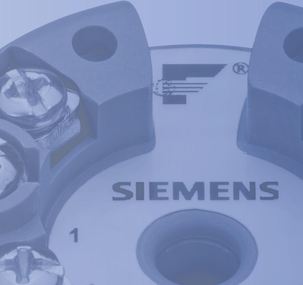
14 Description 3.4 Type plate structure PROFIBUS PA function blocks: Two analog FOUNDATION fieldbus function blocks: Two analog and one PID FOUNDATION fieldbus functionality: Basic or LAS. Galvanical isolation Intrinsically safe version for use in hazardous areas Special characteristic curve 3.4 Type plate structure The type plate is located on the housing and carries the order number and other important product information; see following example. Figure 3-1 Example: Type plate 1 Manufacturer 5 Order number 2 Pay attention to the Operating Instructions 6 Serial number with coded production year and production month. 3 Version; 7 Type designation PROFIBUS PA or FOUNDATION fieldbus 4 Hardware and firmware revision 8 Place of manufacture 14 Operating Instructions, 02/2007, A5E
15 Description 3.5 Mode of operation 3.5 Mode of operation In what follows, the mode of operation of the transmitter is explained using the function block diagram. The two versions of the (7NG and 7NG ) are distinguished solely by the type of the fieldbus protocols (PROFIBUS PA or FOUNDATION fieldbus). Figure 3-2 Function block diagram Operating Instructions, 02/2007, A5E
16 Description 3.6 System communication 3.6 System communication s s Figure 3-3 Communications interface 16 Operating Instructions, 02/2007, A5E
17 Assembly 4 Notice The transmitter is intended only for installation in the type B connection head or larger. Caution Before assembling the head-mounted transmitter, observe the following notes: Install the transmitter in a suitable housing. Adapt the degree of protection and the housing material to the specific requirements. Comply with the ambient conditions specified in the technical data. Springs and fixing screw for the transmitter are included in the delivery. The transmitter may be secured optionally in the base of the connection head or in the raised cover of the connection head. Securing the transmitter in the connection head base Securing the transmitter in the connection head cover 1 Transmitter 1 Transmitter 2 Connection head 2 Ceramic base of the measuring element 3 Connection head Operating Instructions, 02/2007, A5E
18 Assembly 18 Operating Instructions, 02/2007, A5E
19 Connecting Bus installation s s Figure 5-1 Bus installation using PROFIBUS PA as an example. The FOUNDATION fieldbus should be connected correspondingly. Operating Instructions, 02/2007, A5E
20 Connecting 5.2 General connection notes 5.2 General connection notes Warning Electrical connection in hazardous zones with explosive atmospheres For electrical connection, observe the national directives and laws for hazardous areas valid in your country. For example, in Germany, the following hold: the working reliability regulation; the directive for the installation of electrical systems in hazardous areas, DIN EN (previously VDE 0165, T1) the EC-type examination certificate. If a power supply is required, check to see if the specifications on power supply agree with those on the type plate and the inspection certificate valid in your country. Connecting the sensor, cf. chapter: Options for sensor connection assignments (Page 24) Bus connection: The transmitter is connected with its connecting terminals "1" and "2" to the segment coupler. The transmitter acts independent of polarity. Connection cable: Max. cable cross-section 2.5 mm 2 ; Install the signal cable separately from cables with voltages of U > 60 V; Use cable with twisted wires; Avoid getting too close to large electrical systems or use shielded cables; Full specification according to PROFIBUS PA or FOUNDATION fieldbus only with shielded cables; Use only cable entries and covers that are approved for the relevant use; At an ambient temperature of T 60 C, use heat-resistant cables approved at least for an ambient temperature at least 20 K higher. 20 Operating Instructions, 02/2007, A5E
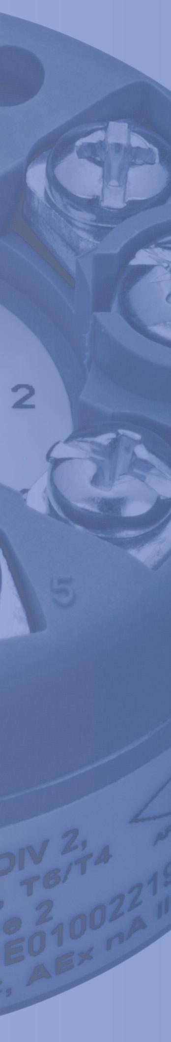
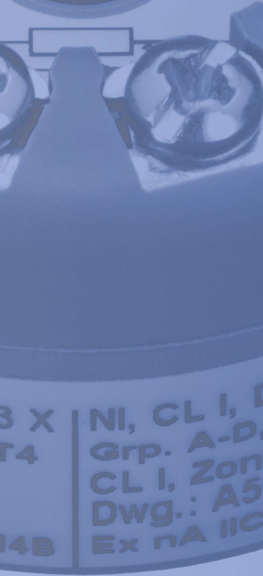
21 Connecting 5.3 Connection in hazardous zones with explosive atmospheres 5.3 Connection in hazardous zones with explosive atmospheres Warning When installing the device in hazardous areas, use housings with the degree of protection corresponding to the inspection certificate valid in your country. Observe the specifications of the EC-type examination certificate or the inspection certificate valid in your country. The bus input circuit and sensor circuit are galvanically isolated and tested with a test voltage of AC 500 V/1 minute. According to the intrinsic safety rules of explosion protection, the requirements for separating the bus input circuit from the ground are met. The galvanical isolation does not meet the requirements for an "infallible galvanical isolation" in the sense of the intrinsic safety standards EN or IEC Be sure to observe the construction directives valid at the construction location for electrical resources in hazardous areas. In Europe, this is the standard EN Use only cable entries and covers that are approved for the relevant use. At an ambient temperature 60 C, use heat-resistant cables approved at least for an ambient temperature at least 20 K higher. Zone 0 and Zone 1 Only connect the transmitter to devices that are certified as intrinsically safe in accordance with the EC-type examination certificate. Be sure to comply with the parameters and limits listed there. If the connection head is made of aluminum, the requirements of EN 50284, section must be observed for uses where the device category 1 G is required. Zone 2 in type of protection "nl" - limited energy Install the transmitter in a housing meeting the protection IP54 per EN 60529, e.g. in a type B connection head per DIN Only connect the transmitter to the following devices: Devices that are certified as intrinsically safe in category 1 or 2. "nl" certified devices (limited energy) in category 3. The maximum approved input voltage is Ui = DC 30 V. Observe the relevant permitted values for external capacitance and inductance. You can find the permissible values in the chapter "Technical data". Operating Instructions, 02/2007, A5E
22 Connecting 5.3 Connection in hazardous zones with explosive atmospheres Zone 2 in type of protection "na" - non-sparking Install the transmitter in a housing meeting the protection IP54 per EN 60529, e.g. in a type B connection head per DIN Adhere to the conditions for installers applicable to this type of protection. The maximum approved input voltage is Um = DC 32 V. Take measures to ensure that the supply voltage does not rise above 40% of the rated voltage. Additional requirements for use in dust explosion protected areas Only use the transmitter in a potentially explosive atmosphere with flammable dust when the following points are ensured: The transmitter is installed in a form B metal head in accordance with DIN The metal head must have a protection of at least IP6X in accordance with EN The transmitter is approved for use in an explosive atmosphere with flammable dust. For a dust layer up to 5 mm thick a surface temperature of the housing 20 K above the ambient temperature is permissible. If the transmitter is used in a potentially explosive atmosphere consisting of an air/dust mixture and the housing used is made of aluminum, observe the requirements from chapter of IEC Operating Instructions, 02/2007, A5E
23 Connecting 5.4 Connection assignments 5.4 Connection assignments s W 5 6 Figure 5-2 connections ➀ Fixing screw M4x30 ➁ Inside diameter of center hole 6.3 mm (0.25 inch) 3 Fixing screws for the connecting cables 1 to 6 Operating Instructions, 02/2007, A5E
24 Connecting 5.5 Options for sensor connection assignments 5.5 Options for sensor connection assignments Resistance thermometer Thermocouple Two-wire input 1) Cold junction compensation, internal Three-wire input Cold junction compensation with external Pt100 in two-wire input 1) Four-wire input Cold junction compensation with external Pt100 in three-wire input Determination of mean value, difference, or redundancy, 2 two-wire inputs 1) Determination of mean value/difference with internal cold junction compensation 1) Line resistance to the correction can be programmed 24 Operating Instructions, 02/2007, A5E
25 Connecting 5.5 Options for sensor connection assignments Resistance thermometer Thermocouple Determination of mean value, difference, or redundancy: One sensor in two-wire input 1) One sensor in three-wire input Determination of mean value, difference, or redundancy and cold junction compensation with external Pt100 in two-wire input 1) 1) Line resistance to the correction can be programmed Further connection assignments are found on the next page. Operating Instructions, 02/2007, A5E
26 Connecting 5.5 Options for sensor connection assignments Resistance Voltage measurement Two-wire input 1) Three-wire input A power supply Four-wire input Determination of mean value, difference, or redundancy One resistance in two-wire input 1) or One resistance in three-wire input Measuring mean value, difference, and redundancy using two power supplies 1) Line resistance to the correction can be programmed 26 Operating Instructions, 02/2007, A5E
27 Functions Summary You can find detailed information about the software of the - PA/FF for PROFIBUS PA or FOUNDATION fieldbus in the following Programming Manual: PROFIBUS PA: Configuration manual, document number A5E ; FOUNDATION field bus: Configuration manual, document number A5E You can find both documents on the "sitrans t - temperature transmitters" CD, ordered separately, order number A5E or on the Internet at Device address PROFIBUS PA Note Before operating two or more field devices, make sure that the device addresses are set on the bus. Assign each address only once, so that the addresses are allocated uniquely. The address range is from 1 to 125. From the warehouse, the -PA is set to the address 126. Normally in the PROFIBUS PA systems the masters are assigned the lower addresses. Begin the address assignment at 30. Operating Instructions, 02/2007, A5E
28 Functions 6.2 Device address FOUNDATION field bus Note The following points are necessary for the -FF to function properly: a unique node address; a physical device identifier for the fieldbus. The node address must be unique within the link (segment), while the physical device identifier must be unique within the entire network. When delivered, the -FF has a unique physical device identifier. The device identifier is a concatenation of the string "" and part of the serial number. The node address is set to "22". In the unit configuration, set the node address to a value that is unique within the link. To avoid address conflicts, the -FF automatically sets its address to one of the temporary standard addresses between 248 and 251 as soon as it recognizes another device with the same node address. 28 Operating Instructions, 02/2007, A5E
29 Functions 6.3 Device delivery condition 6.3 Device delivery condition The device parameters of the - PA/FF are set to default values. You will find the default settings in the relevant "Configuration Manuals". When the is delivered, the following parameters are set differently from the default assignment: Parameter -PA (7NG3214) Break monitoring, channel 1 Short circuit monitoring, channel 1 -FF (7NG3215) Break monitoring, channel 1 Short circuit monitoring, channel 1 Set value ON OFF ON OFF Excerpt of important default values for -PA and -FF Sensor Pt100 (IEC) Connection type Three-wire input Unit C Failure behavior Last valid value Filter time 0 s Only for -PA devices PA address 126 PROFIBUS identification Manufacturer-specific number Only for -FF devices Node address 22 Operating Instructions, 02/2007, A5E
30 Functions 6.4 Simulation mode 6.4 Simulation mode Simulation mode in PROFIBUS PA The simulation mode of the PROFIBUS PA has no simulation write protection Simulation mode with FOUNDATION fieldbus Note To use the simulation mode in FOUNDATION fieldbus you need a special magnetic pin to enable the software simulation mode. You can obtain this magnetic pin from technical support in the Internet at To switch to the software simulation mode in the FOUNDATION fieldbus version, place to the connecting terminals 1 and 2 on the special magnetic pin; see the following picture. s W 5 6 Figure 6-1 Activation of reed contact in FF Magnetic pin Connecting terminal FF As long as the device is operated in simulation mode, the magnetic pin must be located on the device. 30 Operating Instructions, 02/2007, A5E
31 Service and maintenance 7 The device is maintenance-free Operating Instructions, 02/2007, A5E
32 Service and maintenance 32 Operating Instructions, 02/2007, A5E
33 Technical data 8 Input Measurement rate of the analog-to-digital conversion Resolution of the analog-to-digital conversion < 50 ms 24 Bit Resistance thermometer and linear resistance input: Resistance thermometer Min. value Max. value Standard Pt25... Pt C +850 C IEC60751/JIS C 1604 NI25... Ni C +250 C DIN Cu10... Cu C +200 C α = Line resistance per sensor cable Sensor current Max. 50 Ω Nominal 0.2 ma Sensor fault recognition Sensor break recognition Sensor short circuit recognition Short circuit recognition Yes Yes < 15 Ω Input of resistance-type transmitter Resistance-type Min. value Max. value transmitter Resistance-type transmitter 0 Ω 10 kω Line resistance per sensor cable Sensor current Max. 50 Ω Nominal 0.2 ma Sensor fault recognition Sensor break recognition Sensor short circuit recognition Short circuit recognition Yes Yes < 15 Ω Operating Instructions, 02/2007, A5E
34 Technical data Thermocouple input: Type Min. value Max. value Standard B +400 C C IEC584 E -100 C C IEC 584 J -100 C C IEC 584 K -100 C C IEC 584 L -200 C +900 C DIN N -180 C C IEC 584 R -50 C C IEC 584 S -50 C C IEC 584 T -200 C +400 C IEC 584 U -200 C +600 C DIN W3 0 C C ASTM E W5 0 C C ASTM E External cold junction -40 C +135 C IEC compensation Sensor fault recognition Sensor break recognition Sensor short circuit recognition Short circuit recognition Sensor current in case of break monitoring Yes Yes < 3 mv 4 μa Millivolt transmitter - voltage input Measuring range Input resistance mv 10 MΩ Output Filter time (programmable) Updating time s < 400 ms Power supply Supply voltage: Standard DC V ATEX, FM, UL, and CSA DC V In FISCO installation DC V 34 Operating Instructions, 02/2007, A5E
35 Technical data Supply voltage: Power consumption Max. increase of power consumption in case of fault < 11 ma < 7 ma Ambient condition Warning Explosion hazard The specifications of the permissible ambient temperatures are not valid for use in hazardous areas. Observe the approvals and certificates. Permissible ambient temperature Permissible storage temperature Relative humidity C (-40 to +185 F) C (-40 to +185 F) 98%, condensing Dielectric strength Test voltage Continuous operation AC 500 V for 60 s AC 50 V/DC 75 V Mechanical testing Vibrations (DIN class B) IEC and IEC g/ Hz Measuring accuracy The accuracy is defined as the higher value of general values and basic values. General values Input type Absolute accuracy Temperature coefficient All ±0.05% of measured value ±0.002% of measured value / C Basic values Input type Basic accuracy Temperature coefficient Pt100 and Pt1000 ±0.1 C ±0.002 C / C Ni100 ±0.15 C ±0.002 C / C Operating Instructions, 02/2007, A5E
36 Technical data Basic values Cu10 ±1.3 C ±0.02 C / C Resistance-type transmitter ±0.05 Ω ±0.002 Ω / C Voltage sensor ±10 μv ±0.2 Ω / C Thermocouple type: ±0.5 C ±0.010 C / C E, J, K, L, N, T, U Thermocouple type: ±1 C ±0.025 C / C B, R, S, W3, W5 Cold junction compensation < ± 0.5 C Reference conditions Heat-up time 30 s Signal-to-noise ratio Min. 60 db Calibration condition C EMC EMC of interference voltage influence Extended EMC interference immunity: NAMUR NE 21, criterion A, burst < ±0.1% of the measuring span < ±1% of the measuring span Regulations observed EMC 2004/108/EC Emission and interference immunity Standard EN Approvals Regulations observed Standard ATEX 94/9/EC EN 50014, EN 50020, EN , EN 50284, IEC (FISCO) FM 3600, 3610, 3611 CSA, CAN/CSA C22.2 No. 142, No. 157, No. 213 CAN/CAS E79-0, -11, -15 Construction Dimensions Degree of protection (transmitter housing/terminal) Weight 44 x 26.3 mm IP40/IP00 55 g 36 Operating Instructions, 02/2007, A5E
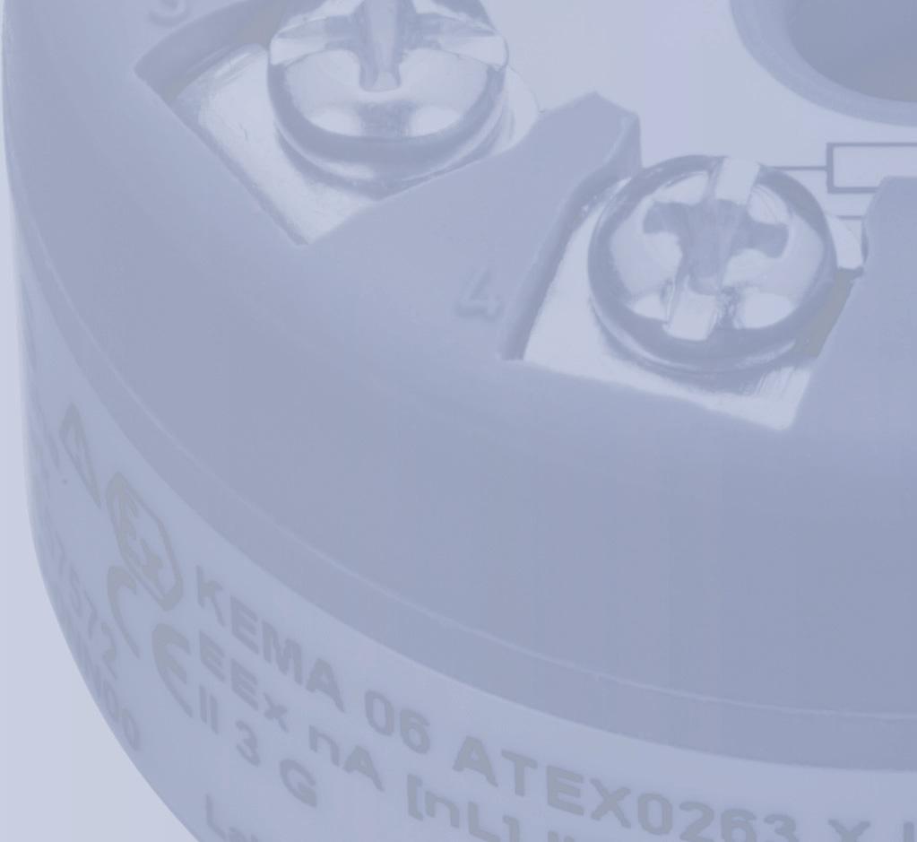
37 Technical data Certificates and approvals Notice For uses in hazardous areas, only the specifications of the inspection certificates valid in your country apply. Approval for operation in hazardous areas zone 0 and zone 1 KEMA 06 ATEX 0264 X 7NG3214-0AN00 or 7NG3215-0AN00 II 1 GD or II 2 (1) GD, T65 C... T105 C EEx ia IIC or EEx ib [ia] IIC T4... T6 Electrical specifications Intrinsically safe supply voltage at Po < 0.84 W Input parameters: Terminals 1 and 2 Intrinsically safe supply voltage at Po < 1.3 W Use in FISCO systems at Uo= 17.5 V Use in FISCO systems at Uo= 15 V Ui DC 30 V DC 30 V DC 17.5 V DC 15 V Ii AC 120 ma AC 300 ma AC 250 ma AC 900 ma Pi 0.84 W 1.3 W 2.0 W 5.32 W Li 1 μh 1 μh 1 μh 1 μh Ci 2.0 nf 2.0 nf 2.0 nf 2.0 nf Output parameters: Terminals 3, 4, 5, and 6 UO 5.7 V IO 8.4 ma PO 12 mw LO 200 mh CO 40 µf Permissible ambient temperature Temperature C C C C class T1... T4 Temperature C C C C class T5 Temperature class T C C C C Operating Instructions, 02/2007, A5E
38 Technical data Approval for operation in hazardous areas zone 2 KEMA 06 ATEX 0263 X 7NG3214-0NN00 7NG3215-0NN00 EEx na [nl] II C T4... T6 Input parameters: Terminals 1 and 2 in the degree of protection "na" Ui Permissible ambient temperature Temperature class T1... T4 Temperature class T5 Temperature class T6 DC 32 V C C C Input parameters: Terminals 1 and 2 in the degree of protection "nl" FNICO Ui Li Ci Permissible ambient temperature Temperature class T1... T4 Temperature class T5 Temperature class T V 1 μh 2.0 nf C C C Output parameters: Terminal 3, 4, 5, and 6 for connecting thermocouples and resistance thermometer in the degrees of protection "na" and "nl": Uo Io Po Lo Co DC 5.7 V 8.4 ma 12 mw 200 mh 40 μf FM approvals for USA 7NG3214-0AN00 7NG3215-0AN00 FM IS Class I, Div 1, Groups A, B, C, D T4/T5/T6, FISCO IS Class I, Zone 0, AEx ia, IIC T4/T5/T6, FISCO NI Class I, Div 2, Groups A, B, C, D T4/T5/T6, FNICO FM approvals for USA FM NG3214-0NN00 7NG3215-0NN00 NI Class I, Div 2, Groups A, B, C, D T4/T5/T6, FNICO The complete parameters (entity) and rated conditions can be found in the FM certificate of compliance no and the installation drawing A5E A. 38 Operating Instructions, 02/2007, A5E
39 Technical data CSA approvals for Canada 7NG3214-0AN00 7NG3215-0AN00 CSA IS Class I, Groups A, B, C, D T4/T5/T6 Ex ia IIC T4/T5/T6 and Ex ib [ia] IIC T4/T5/T6 CSA approvals for Canada 7NG3214-0NN00 7NG3215-0NN00 CSA Class I, Div 2, Groups A, B, C, D T4/T5/T6 Ex na II T4/T5/T6 and Ex ib [ia] IIC T4/T5/T6 The complete parameters (entity) and rated conditions can be found in the CSA certificate of compliance no and the installation drawing A5E A. Parameter assignment interface PROFIBUS PA connection: PROFIBUS PA protocol A&D profile, ver. 3.0 PROFIBUS PA protocol standard EN vol. 2 PROFIBUS PA address (on delivery) 126 PROFIBUS PA function blocks Two analog FOUNDATION fieldbus connection FOUNDATION fieldbus protocol FF protocol FOUNDATION fieldbus protocol standard FF design regulations FOUNDATION fieldbus functionality Basic or LAS FOUNDATION fieldbus version ITK 4.6 FOUNDATION fieldbus function blocks Two analog and one PID Operating Instructions, 02/2007, A5E
40 Technical data 40 Operating Instructions, 02/2007, A5E
41 Dimension drawings 9 Dimension drawing for s W Figure 9-1 dimensions Note The dimensions hold for PROFIBUS PA and FOUNDATION fieldbus. Operating Instructions, 02/2007, A5E
42 Dimension drawings 42 Operating Instructions, 02/2007, A5E
43 Index C Componentry At electrostatic risk, 10 Correct usage, 9 E Electrical connection Hazardous area, 9 F Firmware, 7 Firmware identification Type plate, 7 Flameproof enclosure, 10 H Hazardous area Electrical connection, 9 History, 7 Q Qualified personnel, 11 S Standard fieldbus, 7 System integration, 7 T Type of protection Flameproof enclosure, 10 Intrinsic safety, 10 Limited energy nl (zone 2), 10 Non-sparking na (zone 2), 10 W Working reliability regulation, 9 worldwide Contact person, 8 Worldwide contact person, 8 I Installation path PDM, 7 Intrinsic safety, 10 Z Zone 2, 10 M More information, 8 P Precautions, 10 Product information on the Internet, 8 Operating Instructions, 02/2007, A5E
44 A5E A5E Siemens Aktiengesellschaft Automation and Drives (A&D) Sensors and Communication Process Sensors KARLSRUHE GERMANY
Operating Instructions Edition 11/2005. Process monitoring Ex-barrier for Diagnostics Unit SITRANS DA400 7MJ2010-1AA. sitrans
 Operating Instructions Edition 11/2005 Process monitoring Ex-barrier for Diagnostics Unit SITRANS DA400 7MJ2010-1AA sitrans Introduction 1 General safety instructions 2 SITRANS Process monitoring Ex-barrier
SITRANS T. SITRANS T Explosion protected temperature sensor. General information. Marking of the degree of protection. Range of uses.
 General information 1 Marking of the degree of protection 2 SITRANS T SITRANS T Explosion protected temperature sensor Operating Instructions Range of uses 3 Installation 4 Assembly and disassembly 5 Commissioning
SITRANS. Temperature transmitter Functional safety for SITRANS TW. Introduction. General safety instructions 2. Device-specific safety instructions
 Introduction 1 General safety instructions 2 SITRANS Temperature transmitter Device-specific safety instructions 3 Appendix List of Abbreviations/Acronyms A B Product Information Supplement to Operating
Temperature Measurement Transmitters for field mounting
 Siemens AG 07 Overview Application The SITRANS TF can be used everywhere where temperatures need to be measured under particularly harsh conditions. For that reasons users from all industries have opted
Model 144H. Product Data Sheet , Rev DB February Content
 Rosemount 144 PC-Programmable Temperature Transmitter Provides an installation-ready solution for temperature monitoring applications using Complete Point Solutions (CPS) Increases measurement accuracy
FAHM Co. Temperature Transmitter PTT74 Series
 FAHM Co. PTT74 Series The PTT74 is a versatile temperature transmitter that delivers field reliability and advanced accuracy and stability to meet demanding process needs. PTT74 Family of Transmitters
SITRANS T temperature transmitters A broad product family for every application. sitrans
 SITRANS T temperature transmitters A broad product family for every application sitrans The SITRANS T family High-precision, intrinsically safe, and available for a wide variety of sensors Whether you
Functional Safety Manual June pointek CLS500/LC500
 Functional Safety Manual June 2009 pointek CLS500/LC500 Introduction 1 Level Switch Pointek CLS500 SITRANS LC500 SIL Safety Manual Supplement to device manual General safety instructions 2 Device-specific
Installing the assembly SIMATIC. Installing the assembly. Overview 1. Installing the assembly. Getting Started A5E
 Overview 1 2 SIMATIC Getting Started 03/2013 A5E03973659-01 Legal information Warning notice system This manual contains notices you have to observe in order to ensure your personal safety, as well as
Model 144H. Product Data Sheet , Rev DB February Content
 Rosemount 144 PC-Programmable Temperature Transmitter Provides an installation-ready solution for temperature monitoring applications using Complete Point Solutions (CPS) Increases measurement accuracy
Inductive slot sensor
 0102 Model Number Features 2 mm slot width Technical Data specifications Switching function Normally closed (NC) Output type NAMUR Slot width 2 mm Depth of immersion (lateral) 5... 7 mm, typ. 6 mm Output
... RD0-TI-Ex8.FF.* Temperature Multi-Input Device for Cabinet Installation. Features. Assembly. Function. Connection. Zone 1
 emperature Multi-Input Device for Cabinet Installation Features Assembly For 8 temperature or analog sensors Installation in Zone 1/Div. 1, intrinsically safe Sensors in Zone 0/Div. 1 Connection to fieldbus
PROZESSAUTOMATION. Manual SEGMENT PROTECTOR R-SP-!12. Zone 1 Zone 2 / Div 2 FNICO
 PROZESSAUTOMATION Manual SEGMENT PROTECTOR R-SP-!12 FieldConnex TM Segment Protectors with overloaod protection and short-circuit current limitation for the connection of 12 field devices Zone 1 Zone 2
SITRANS T. Temperature transmitter SITRANS TH100. Introduction 1. General safety information 2. Description 3. Assembly 4. Connecting 5.
 Introduction 1 General safety information 2 SITRANS T Temperature transmitter Operating Instructions Description 3 Assembly 4 Connecting 5 Operation 6 Commissioning 7 Functions 8 Service and maintenance
Technical Data. Dimensions
 0102 Model Number Features 8 mm non-flush Stainless steel housing Usable up to SIL2 acc. to IEC 61508 Technical Data specifications Switching element function NAMUR, NC Rated operating distance s n 8 mm
Additional Operating Instructions SITRANS F. Vortex flowmeters. SITRANS FX330 Ex-nA.
 Additional Operating Instructions SITRANS F Vortex flowmeters Ex-nA Edition 08/207 CONTENTS Safety instructions 3. General notes... 3.2 EU conformity... 3.3 Approval according to the IECEx scheme... 3.4
Technical Data. General specifications Switching element function Rated operating distance s n 5 mm
 0102 Model Number Features 5 mm flush Usable up to SIL 3 acc. to IEC 61508 Application Danger! In safety-related applications the sensor must be operated with a qualified fail safe interface from Pepperl+Fuchs,
PEPPERL+FUCHS GmbH
 Comfort series 1.5 mm embeddable M8x1 4 25 16 13 LED Switching element function NAMUR NC Rated operating distance s n 1,5 mm Installation embeddable Assured operating distance s a 0... 1,215 mm Reduction
Additional Operating Instructions SITRANS F. Vortex flowmeters. SITRANS FX330 Ex-d.
 Additional Operating Instructions SITRANS F Vortex flowmeters Ex-d Edition 09/208 CONTENTS Safety instructions 3. General notes... 3.2 EU conformity... 3.3 Approval according to the IECEx scheme... 3.4
Additional Operating Instructions SITRANS F. Vortex flowmeters. SITRANS FX330 Ex-i.
 Additional Operating Instructions SITRANS F Vortex flowmeters Ex-i Edition 09/2018 CONTENTS 1 Safety instructions 3 1.1 General notes... 3 1.2 EU conformity... 3 1.3 Approval according to the IECEx scheme...
Certificate of Compliance
 FF0002 Certificate of Compliance Certificate: 2792948 Issued to: Siemens Canada Limited 1954 Technology Drive Peterborough, ON K9J 7B1 Canada Attention: Mr. Lee Rogers The products listed below are eligible
User s Manual YTA610 and YTA710 NEPSI Certification
 User s Manual YTA60 and YTA70 NEPSI Certification [Option code: /NS, /NS5 and /NF] st Edition . INTRODUCTION Thank you for purchasing the YTA60 and YTA70 Temperature transmitters. This manual contains
OilSET Installation and Operating Instructions. Oil Separator Alarm Device with SET/DM3AL sensor
 Labkotec UK Ltd Adminicle House 1 Lumb Lane Audenshaw Manchester M34 5WH GREAT BRITAIN Tel: 0844 3350 477 Fax: 0161 4281 179 E-mail: info@labkotec.co.uk 10.8.2012 Internet: www.labkotec.co.uk 1/13 OilSET-1000
Safety instructions VEGADIF DF65.GX*****H/Z/P/F***** IECEx BVS
 Safety instructions VEGADIF DF65.GX*****H/Z/P/F***** IECEx BVS 10.0008 Ex td A20, A20/21, A20/22, A21 IP66 T 0044 37675 Contents 1 Area of applicability 3 2 General information 3 2.1 Zone 20 instruments
7NG , 7NG
 SITRANS TK-- L 7NG3120-- 0, 7NG3122-- 0 Edition 01/2003... Transmitter for temperature (Pt100) O per at ing ins t r uc t... ions SITR AN S TK--L A 5E 00095604-- 02 1 SIMATICr, SIPARTr, SIPROMr, SIRECr,
Technical Data. Dimensions
 0102 Model Number Features 5 mm flush Usable up to SIL2 acc. to IEC 61508 Accessories EXG-18 Quick mounting bracket with dead stop BF 18 Mounting flange, 18 mm Technical Data specifications Switching element
Technical Data. General specifications Switching element function Rated operating distance s n 5 mm
 0102 Model Number Features 5 mm non-flush Usable up to SIL2 acc. to IEC 61508 Technical Data specifications Switching element function NAMUR, NC Rated operating distance s n 5 mm Installation non-flush
Technical Data. General specifications Switching element function DC Dual NC Rated operating distance s n 3 mm
 0102 Model Number Features Direct mounting on standard actuators EC-Type Examination Certificate TÜV99 ATEX 1479X Accessories BT32 BT32XS BT32XAS BT33 BT34 V1-G-N4-5M-PUR Female cordset, M12, 4-pin, NAMUR,
Annubar Flowmeter Series
 Reference Manual Appendix B Approvals Annubar Flowmeter Series Hazardous Locations Installations.................. page B-1 Rosemount 3051SFA Product Certifications.......... page B-1 Rosemount 3095MFA
Technical Data. General specifications. Rated operating distance s n 5 mm
 0102 Model Number Features 5 mm non-flush Usable up to SIL 2 acc. to IEC 61508 Technical Data specifications Switching function Normally closed (NC) Output type NAMUR Rated operating distance s n 5 mm
Installing Foundation Fieldbus H1 in Hazardous Areas. Presented By: Jim Peterson Sr. Applications Engineer MTL/USA
 Installing Foundation Fieldbus H1 in Hazardous Areas Presented By: Jim Peterson Sr. Applications Engineer MTL/USA (Divisions) (Zones) Zone 0 ia) Intrinsically Safe Class I Division 1 Explosion Proof Purged
itemp RTD TMT 187 itemp TC TMT 188 Temperature head transmitter
 BA 104R/24/ae/10.03 itemp RTD TMT 187 itemp TC TMT 188 Temperature head transmitter Operating instructions RTD TC TMT 187 TMT 188 Temperature head transmitter Safety message # Warning! Instructions and
Product Information to the manual
 Product Information to the manual Distributed I/O device ET 200iS, Version 10/2001 Introduction This product information contains fixes and additional information relevant to the user manual Distributed
RADAR LEVEL GAUGE SPECIAL SAFETY INSTRUCTION
 Special Safety Instruction en RADAR LEVEL GAUGE SPECIAL SAFETY INSTRUCTION Contents TankRadar Pro European ATEX Directive Information............................... 2 ATEX marking and Ex Certification
SET Installation and Operating Instructions. Level switch for one sensor
 Labkotec Oy Myllyhaantie 6 FI-33960 PIRKKALA FINLAND Tel.: +358 29 006 260 Fax: +358 29 006 1260 7.11.2013 Internet: www.labkotec.fi 1/14 SET-1000 Level switch for one sensor Copyright 2013 Labkotec Oy
YTA Series Temperature Transmitters [Style: S3] EN :2006, -11:2007, -26:2007. Supply circuit: Ui=30 V, Ii=165 ma,
![YTA Series Temperature Transmitters [Style: S3] EN :2006, -11:2007, -26:2007. Supply circuit: Ui=30 V, Ii=165 ma,](/thumbs/89/98785336.jpg "YTA Series Temperature Transmitters [Style: S3] EN :2006, -11:2007, -26:2007. Supply circuit: Ui=30 V, Ii=165 ma,") User s Manual YTA Series Temperature Transmitters [Style: S3] Manual Change No. 10-008 Please use the attached sheets in the following manuals when the product is with /KU2 option and EN60000 Series based
User s Manual YTA Series Temperature Transmitters [Style: S3] Manual Change No. 10-008 Please use the attached sheets in the following manuals when the product is with /KU2 option and EN60000 Series based
SET-2000 Oil/Sludge 12 VDC
 Labkotec Oy Myllyhaantie 6 FI-33960 PIRKKALA FINLAND Tel: + 358 29 006 260 Fax: + 358 29 006 1260 12.2.2015 Internet: www.labkotec.fi 1/14 SET-2000 Oil/Sludge 12 VDC Alarm Device for Oil Separators with
Technical Data. Dimensions
 0102 Model Number Features 15 mm non-flush Technical Data specifications Switching element function NAMUR, NC Rated operating distance s n 15 mm Installation non-flush Assured operating distance s a 0...
Radar Transmitters SITRANS LR400 (HART/PROFIBUS PA) Quick Start Manual 03/2013 SITRANS
 Quick Start Manual 03/2013 SITRANS") Radar Transmitters SITRANS LR400 (HART/PROFIBUS PA) Quick Start Manual 03/2013 SITRANS SITRANS LR 400 Quick Start Manual This manual outlines the essential features and functions of the SITRANS LR 400
Radar Transmitters SITRANS LR400 (HART/PROFIBUS PA) Quick Start Manual 03/2013 SITRANS SITRANS LR 400 Quick Start Manual This manual outlines the essential features and functions of the SITRANS LR 400
Technical Data. General specifications Switching element function Rated operating distance s n 8 mm
 0102 Model Number Features 8 mm non-flush Usable up to SIL 3 acc. to IEC 61508 Application Danger! In safety-related applications the sensor must be operated with a qualified fail safe interface from Pepperl+Fuchs,
OPTIBAR DP 7060 Supplementary Instructions
 OPTIBAR DP 7060 Supplementary Instructions Differential pressure transmitter Category ATEX II 1/2G, 2G Ex db ia IIC T6...T1 Ga/Gb, Gb IECEx Ex db ia IIC T6...T1 Ga/Gb, Gb Housing Aluminium: Single chamber,
Additional Information. Introduction. Temperature transmitter for all communications protocols. Redundancy thanks to two inputs. Measurement made easy
 ABB MEASUREMENT & ANALYTICS COMMISSIONING INSTRUCTION TTF300 Field-mount temperature transmitter Temperature transmitter for all communications protocols. Redundancy thanks to two inputs. Measurement made
Certificate of Compliance
 Certificate of Compliance Certificate: 70033893 (166720) Issued to: WIKA Alexander Wiegand SE & Co. KG Alexander-Wiegand-Str 30 Klingenberg, 63911 GERMANY Attention: Uwe Schmidt The products listed below
5.1 Safety instructions for system configuration and explosion protection. Zone-specific conditions for system configuration
 Planning and configuration of the I.S. 1 system 5 ENGINEERING 5.1 Safety instructions for system configuration and explosion protection During engineering, comply with the guidelines set out in EN 60 079-14.
SBEx-4 BISTATE SEPARATOR 1, 2, 3 or 4 channels in rail housing (TS35, 22,5mm width)
") SBEx-4 BISTATE SEPARATOR,, 3 or 4 channels in rail housing (TS3,,mm width) - group I category (M), group II and III category () accompanying device, - intrinsically safe input circuits with ia protection
SBEx-4 BISTATE SEPARATOR,, 3 or 4 channels in rail housing (TS3,,mm width) - group I category (M), group II and III category () accompanying device, - intrinsically safe input circuits with ia protection
Temperature measurement with SITRANS T siemens.com/processinstrumentation
 Top values in precision and reliability Temperature measurement with SITRANS T siemens.com/processinstrumentation Temperatures firmly under control Top process quality and efficiency are key factors for
AM54. Armored Variable Area Flowmeter Series AM54331/32 Series AM54371/72/73/74 Series AM54431/32 Series AM54471/72/73/74
 AM54 Instruction Bulletin North American Installation Addendum Document Number PN25016 Armored Variable Area Flowmeter Series AM54331/32 Series AM54371/72/73/74 Series AM54431/32 Series AM54471/72/73/74
SITRANS Pressure transmitter SITRANS LH300 (7MF1575..) Transmitter for hydrostatic level Compact Operating Instructions
 Transmitter for hydrostatic level Compact Operating Instructions") SITRANS Pressure transmitter Compact Operating Instructions Legal information Warning notice system This manual contains notices you have to observe in order to ensure your personal safety, as well as
SITRANS Pressure transmitter Compact Operating Instructions Legal information Warning notice system This manual contains notices you have to observe in order to ensure your personal safety, as well as
SITRANS F M MAG 3100 P:
 Dedicated for the chemical industry SITRANS F M MAG 3100 P: The electromagnetic flowmeter solution with devoted features. Process Instrumentation usa.siemens.com/mag The best choice for the chemical industry
IECEx Certificate of Conformity
 Page 1 of 10 IECEx Certificate of Conformity INTERNATIONAL ELECTROTECHNICAL COMMISSION IEC Certification Scheme for Explosive Atmospheres for rules and details of the IECEx Scheme visit www.iecex.com Certificate
ABB Instrumentation. Specifications. COMMANDER 150 Universal Process Indicator. the 1 /8 DIN indicator to match all your display requirements
 Specifications COMMANDER 150 Universal Process Indicator High visibility 6-digit LED display the clearest view of your process status 0.1% measurement accuracy precise indication of process measurement
OilSET-1000 (12 VDC)
") Labkotec Oy Myllyhaantie 6 FI-33960 PIRKKALA FINLAND Tel: +358 29 006 260 Fax: +358 29 006 1260 Internet: www.labkotec.fi 20.03.2009 1/11 OilSET-1000 (12 VDC) Oil Separator Alarm Device Copyright 2009
Labkotec Oy Myllyhaantie 6 FI-33960 PIRKKALA FINLAND Tel: +358 29 006 260 Fax: +358 29 006 1260 Internet: www.labkotec.fi 20.03.2009 1/11 OilSET-1000 (12 VDC) Oil Separator Alarm Device Copyright 2009
STT 3000 Series STT250 Smart Temperature Transmitters Specifications Models STT25T EN0l-6091 February 2009
 STT 3000 Series STT250 Smart Temperature Transmitters Specifications Models STT25T EN0l-6091 February 2009 Introduction Honeywell s STT 3000 family of microprocessor based transmitters covers the full
Technical Data. General specifications Switching element function Rated operating distance s n 4 mm
 0102 Model Number Features 4 mm non-flush Accessories BF 12 Mounting flange, 12 mm Technical Data specifications Switching element function NAMUR, NO Rated operating distance s n 4 mm Installation non-flush
Intelligent sensing for every temperature and condition
 More information: www.siemens.com/sitranst www.siemens.com/processinstrumentation siemens.com/sitranst Siemens Industry, Inc. 3333 Old Milton Parkway Alpharetta, GA 30005 1-800-241-4453 info.us@siemens.com
Instrumentation Products and Applications
 1 1/0 Instrumentation Products and Applications 1 Instrumentation Safety barriers I.S. Isolators - DIN rail mounting - Eurocards - Modules Remote I/O Operating and monitoring systems Instrumentation systems
SET-2000 Hi Level/Oil
 Labkotec Oy Labkotie 1 FI-36240 KANGASALA FINLAND Tel: + 358 29 006 260 Fax: + 358 29 006 1260 13.03.2008 Internet: www.labkotec.fi Alarm Device for Oil Separators Copyright 2008 Labkotec Oy We reserve
Technical Data. Dimensions
 0102 Model Number Features Comfort series 50 mm non-flush Technical Data specifications Switching element function NAMUR, NC Rated operating distance s n 50 mm Installation non-flush Output polarity NAMUR
OMC Ex interface unit. Manual. Version 1.2 August Author: Observator Instruments
 OMC-158-2 Ex interface unit Manual Version 1.2 August 2017 Author: Observator Instruments Revisions: 0.1 (October 2016) First issue 0.2 (December 2016) Prototype 0.3 (January 2017) Test release 1.0 (March
User s Manual. EJA Series Differential Pressure and Pressure Transmitters Manual Change No Yokogawa Electric Corporation
 User s Manual EJA Series Differential Pressure and Pressure Transmitters Manual Change No. 12-004 For the models EJA and EJA-A series with option code /KF21, /KU21, /KU22 or /KN26, please use this manual
GETTING STARTED GUIDE NI TC, ±78 mv, 24 Bit, 75 S/s Aggregate
 GETTING STARTED GUIDE NI 9213 16 TC, ±78 mv, 24 Bit, 75 S/s Aggregate This document explains how to connect to the NI 9213. Note Before you begin, complete the software and hardware installation procedures
Operating Manual MS220DA
 ZIEHL industrie elektronik GmbH + Co KG Daimlerstraße 13, D 74523 Schwäbisch Hall + 49 791 504-0, info@ziehl.de, www.ziehl.de Temperature Relays and MINIKA Mains Monitoring Digital Panel Meters MINIPAN
Advanced Diagnostic Gateway with Ethernet and FF-H1 Interface and I/O. Assembly
 Advanced Diagnostic Gateway with Ethernet and FF-H1 Interface and I/O Features Assembly System integration kit for Advanced Diagnostics PCS integration via Diagnostic Manager or device DTM Simple automatic
INSTRUCTION MANUAL. SIL 3 - SIL 2 IIB Group Power Supply for Hazardous Area Equipment DIN-Rail Model PSD1001C PSD1001C
 PSD1001C INSTRUCTION MANUAL SIL 3 SIL 2 IIB Group Power Supply for Hazardous Area Equipment DINRail Model PSD1001C PSD1001C SIL 3 SIL 2 IIB Group Power Supply for hazardous Area Equipment ISM006510 General
Pressure sensors. Ex ia I / IIC T6 acc. to ATEX. Features. Description. Measuring ranges. Applications
 Force Pressure Temperature Switch Pressure sensors Ex ia I / IIC T6 acc. to ATEX with internal diaphragm with front flush diaphragm Accuracy: 0,25% and 0,5 % Standard output: 4...20 ma; 2-wire system Description
Fieldbus Non-Incendive Concept takes FISCO into Zone 2 and Division 2 hazardous areas. Phil Saward
 Foundation Fieldbus End Users Council Australia Inc. 9 Corcoran St Duncraig, WA 6023 P.O.Box Z5546 Perth, WA 6831 AUSTRALIA ABN 60 120 236 370 Fieldbus Non-Incendive Concept takes FISCO into Zone 2 and
PROFIBUS-PA Display RID 261 PROFIBUS-PA
 Technical Information TI 071R/09/en Mat.-Nr.: 510 01194 PROFIBUS-PA Display RID 261 PROFIBUS-PA Display of process values and set point alarms on PROFIBUS-PA systems R Applications Direct connection to
OilSET Installation and Operating Instructions. Oil Separator Alarm Device
 Labkotec Oy Myllyhaantie 6 FI-33960 PIRKKALA FINLAND Tel: +358 29 006 260 Fax: +358 29 006 1260 18.11.2010 Internet: www.labkotec.fi 1/10 OilSET-1000 Oil Separator Alarm Device Copyright 2010 Labkotec
SET-2000 Oil/Sludge. Alarm Device for Oil Separators. Installation and Operating Instructions
 SET-000 Oil/Sludge Alarm Device for Oil Separators Copyright 007 Labkotec Oy We reserve the right for changes without notice TABLE OF CONTENTS GENERAL... INSTALLATION... 4. SET-000 Oil/Sludge Control Unit...
ISOMETER IRDH375. Insulation monitoring device for unearthed AC, AC/DC and DC systems (IT systems)
") Insulation monitoring device for unearthed AC, AC/DC and DC systems (IT systems) IRDH375_D00124_01_D_XXEN/07.2018 Insulation monitoring device for unearthed AC, AC/DC and DC systems (IT systems) Product
Insulation monitoring device for unearthed AC, AC/DC and DC systems (IT systems) IRDH375_D00124_01_D_XXEN/07.2018 Insulation monitoring device for unearthed AC, AC/DC and DC systems (IT systems) Product
POINTEK CLS 100 OINTEK CLS 100 CAPACITANCE LIQUIDS/SOLIDS. Instruction Manual March 2001
 POINTEK CLS 100 CAPACITANCE LIQUIDS/SOLIDS Instruction Manual March 2001 OINTEK CLS 100 Safety Guidelines Warning notices must be observed to ensure personal safety as well as that of others, and to protect
Rosemount 3144P Rosemount 3144P Temperature Transmitter
 Temperature Transmitter Sensor Drift Alert and Hot Backup features improve measurement reliability while the Transmitter-Sensor Matching feature improves temperature measurement accuracy Statistical Process
DB5 Intrinsically Safe Sounder Type DB-5
 Operating Instructions RTK Instruments Limited DB5 Intrinsically Safe Sounder Type DB-5 Description The DB5 Sounder is a strong, lightweight warning sounder, CENELEC certified to Ex II 1G EExia IIC T4
SINAMICS G130. Cabinet design and EMC. Operating instructions 03/2011 SINAMICS
 SINAMICS G130 Operating instructions 03/2011 SINAMICS s Safety information 1 General 2 SINAMICS SINAMICS G130 Basic information about EMC 3 EMC-compliant design and control cabinet configuration 4 Cabinet
Isolated Thermocouple Module
 User Manual for the HE693THM665, HE693THM666, HE693THM667, HE693THM668 Isolated Thermocouple Module Twelfth Edition 19 April 2004 PREFACE 19 APR 2004 PAGE 3 PREFACE This manual explains how to use the
ProcessMaster, HygienicMaster FEX300, FEX500
 SM/FEX300/FEX500/ATEX/IECEX-EN ProcessMaster, HygienicMaster FEX300, FEX500 ATEX / IECEx Zone 1, 2, 21, 22 Safety instructions for electrical apparatus in potentially explosive areas, in accordance with
GETTING STARTED GUIDE NI RTD, 0 Ω to 400 Ω, 24 Bit, 400 S/s Aggregate, PT100
 GETTING STARTED GUIDE NI 9217 4 RTD, 0 Ω to 400 Ω, 24 Bit, 400 S/s Aggregate, PT100 This document explains how to connect to the NI 9217. Note Before you begin, complete the software and hardware installation
SITRANS. Temperature sensors SITRANS TSinsert/TS100/TS200/ TS500. Introduction 1. Safety information 2. Description 3. Installation 4.
 Introduction 1 Safety information 2 SITRANS Temperature sensors SITRANS TSinsert/TS100/TS200/ TS500 Operating Instructions Description 3 Installation 4 Connection 5 Commissioning 6 Service and maintenance
Installation and Operating Instruction
 Installation and Operating Instruction Automatic Fire Detectors Series 900 Ex (i) 9893 0.00 GB Technical changes reserved! 0 Installation and Operating Instruction Automatic Fire Detectors Series 900 Ex
AND INSTALLATION MANUAL
 Labkotec Oy Myllyhaantie 6 FI-33960 PIRKKALA FINLAND Tel. +358 29 006 260 Fax +358 29 006 1260 Internet: www.labkotec.fi 10.10.2013 SET/DM3AL Level sensor OPERATION AND INSTALLATION MANUAL 1(5) SYMBOLS
BA334D Intrinsically safe Externally powered pulse input field mounting rate totaliser Issue 13
 TR Automatyka Sp. z o. o. Tel. (+48 022) 886 10 16 www.trautomatyka.pl ul. Lechicka 14 ; 02-156 Warszawa Fax. (+48 022) 846 50 37 biuro@trautomatyka.pl BA334D Intrinsically safe Externally powered pulse
SINAMICS G130. Cabinet design and EMC. Operating Instructions 05/2010 SINAMICS
 SINAMICS G130 Operating Instructions 05/2010 SINAMICS s Safety information 1 General 2 SINAMICS SINAMICS G130 Basic information about EMC 3 EMC-compliant design and control cabinet configuration 4 Cabinet
ATEX Installation Instructions for Micro Motion F-Series Sensors with Certificate DMT 01 ATEX E 158 X
 Installation Instructions P/N MMI-20010174, Rev. A June 2007 ATEX Installation Instructions for Micro Motion F-Series Sensors with Certificate DMT 01 ATEX E 158 X For ATEX-approved sensor installations
BA338C Intrinsically safe Externally powered pulse input panel mounting rate totaliser issue 13
 BA338C Intrinsically safe Externally powered pulse input panel mounting rate totaliser issue 13 Certification information label Total display Rate display Rotating flow indicator Annunciators for optional
Rosemount 752 Fieldbus Remote Indicator
 Product Data Sheet Rosemount 752 Rosemount 752 Fieldbus Remote Indicator ROSEMOUNT 752 DELIVERS: Two-wire segment powered device Displays up to 8 values Link Master Capability Optional PID, Characterizer,
PROCESS AUTOMATION. Instruction manual. Fieldbus Terminators F*-FT-EX1.I.IEC F*-FT-EX1.D.IEC
 PROCESS AUTOMATION Instruction manual Fieldbus Terminators F*-FT-EX1.I.IEC F*-FT-EX1.D.IEC With regard to the supply of products, the current issue of the following document is applicable: The General
VERSAFLOW VORTEX Supplementary instructions
 VERSAFLOW VORTEX Supplementary instructions Vortex flowmeter Equipment category II 2G CONTENTS VERSAFLOW VORTEX 1 Safety instructions 3 1.1 General notes... 3 1.2 EC conformity... 3 1.3 Approval according
Software Version 2.01 LEVEL MONITOR MODEL 220
 Software Version 2.01 LEVEL MONITOR MODEL 220 19 April 2000 CONTENTS 1. Introduction 1 1.1 Model Number Designation 2 1.2 Intrinsic Safety Considerations 3 2. Specification 4 3. Operation 6 3.1 Display
4) Intrinsic Safety Certification
 Intrinsic Safety Certification") INSTRUCTION MANUAL Minialert Intrinsically Safe Round Combined Unit Section Volume Control Tone Generator S2 S3 Tone Selection Switches Fig 1 Simplified block diagram The combined unit is CE marked for
INSTRUCTION MANUAL Minialert Intrinsically Safe Round Combined Unit Section Volume Control Tone Generator S2 S3 Tone Selection Switches Fig 1 Simplified block diagram The combined unit is CE marked for
Module Features are-configurable, no module jumpers to set
 December 2011 PACSystems* RX3i Isolated Thermocouple Input Module, 6 Channels, IC695ALG306 Isolated Thermocouple Input Module, 12 Channels, IC695ALG312 Isolated Thermocouple Input module IC695ALG306 provides
ISOMETER IRDH275BM-7 with coupling device AGH675-7 and AGH675-7MV15
 with coupling device AGH675-7 and AGH675-7MV15 Device combination for insulation monitoring in unearthed AC, AC/DC and DC power systems (IT systems) IRDH275BM-7_D00123_03_D_XXEN/01.2017 with coupling device
PACSystems* RX3i. Thermocouple Input Module, 12 Channels, IC695ALG412. GFK-2578B October 2011
 October 2011 PACSystems* RX3i Thermocouple Input Module, 12 Channels, IC695ALG412 The PACSystems * Thermocouple Input module IC695ALG412 provides twelve isolated differential thermocouple input channels.
DSF xx15.xx xhv Ex-Atex Ex-Atex Certified Two wire Hall Effect Speed Sensor
 DSF xx15.xx xhv Ex-Atex Product ID Type # Product # Drawing # DSF 1215.01 SHV Ex-atex (5m) 304Z-05197 113216 DSF 1415.01 AHV Ex-atex S148 304Z-05256 113351 DSF 1615.01 SHV Ex-atex (5m) 304Z-05196 113214
INSTRUCTION MANUAL. SIL 2 Load Cell/Strain Gauge Bridge Isolating Converter DIN-Rail Power Bus and Termination Board Model D5264S D5264S
 D5264S INSTRUCTION MANUAL SIL 2 Load Cell/Strain Gauge Bridge Isolating Converter DIN-Rail Power Bus and Termination Board Model D5264S Characteristics General Description: The single channel DIN Rail
Intrinsically Safe, NEMA 4, Type 4X, IP67 Loop-Powered Meter
 PD685 Intrinsically Safe, NEMA 4, Type 4X, IP67 Loop-Powered Meter Actual Size Digits C US Intrinsically Safe 3½ Digits LARGE DISPLAY NEMA 4, Type 4X, IP67 Loop-Powered Field-Mount Process Meter 4-20 ma
Tank Gauging System Special Safety Instruction
 Tank Gauging System www.rosemount-tg.com Rosemount TankRadar REX Table of Contents Contents SPECIAL SAFETY INSTRUCTION........................ 1-1 1. GENERAL REQUIREMENTS....................... 1-2 1.1
GETTING STARTED GUIDE NI Channel, 0 ma to 20 ma, 16-Bit Analog Output Module. This document explains how to connect to the NI 9265.
 GETTING STARTED GUIDE NI 9265 4-Channel, 0 ma to 20 ma, 16-Bit Analog Output Module This document explains how to connect to the NI 9265. Note Before you begin, complete the software and hardware installation
Intrinsically Safe Pressure Transmitters for installation in hazardous locations Models IS-20-S, IS-21-S, IS-20-F, IS-21-F WIKA Datasheet IS-20
 Electronic Pressure Measurement Intrinsically Safe Pressure Transmitters for installation in hazardous locations Models IS-20-S, IS-21-S, IS-20-F, IS-21-F WIKA Datasheet IS-20 Applications Chemical, Petrochemical
DSF xx10.xx xhv Ex-Atex Hall Effect Single Channel Speed Sensor
 Product ID Type # Product # Drawing # DSF 1210.00 SHV Ex-atex (2m) 374Z-05066 110428F1 DSF 1210.00 SHV Ex-atex (5m) 374Z-05176 110428F1 DSF 1210.00 SHV Ex-atex (10m) 374Z-05590 110428F1 DSF 1410.00 SHV
Rosemount 248 Temperature Transmitter
 Product Data Sheet November 2013 00813-0100-4825, Rev KA Rosemount 248 Temperature Transmitter Basic temperature transmitter offers a reliable solution for temperature monitoring points transmitter design