Trios Training Manual
|
|
|
- Dominic Johnson
- 6 years ago
- Views:
Transcription


1 Trios Training Manual Version 1.2, June 2002
2 TRIOS training-manual TRIOS SYSTEM INTRODUCTION... 2 The Trios Concept... 2 Trios Multi-functionality... 2 Trios Flexibility... 2 Trios Simplicity... 2 Trios functionality... 2 Manual control... 2 Manual control with Energy saving... 3 Light sensor combined with infrared remote control... 3 Hands-free control with Energy saving TRIOS SYSTEM OVERVIEW... 4 Connecting peripherals INTERLINKED TRIOS LIGHT CONTROLLERS... 8 Master/slave configurations... 9 Switching lighting loads via external mains contactors Regulating lighting loads DAYLIGHT LINKING Daylight switching (LRC1010/1015) Daylight regulation and Constant lux (1020/25;1030/35) Daylight regulation: Constant Lux level: CHANGING THE REFERENCE LEVEL IN TRIOS Trios controller LRC Trios controller 1020/25; 1030/ Changing the reference level by potentiometer Slow light reactions when reference levels are changed IR remote control for commissioning and for light control IRT 8030 INFRARED REMOTE CONTROL Functionality IR group addresses Changing channel and group addresses of Trios light controllers Changing the channel address Changing the group address FUNCTIONS WITH COMBINED PERIPHERALS Manual / Remote control Trios controller with only a light-sensor, or a light-sensor in combination with a potentiometer... 40
3 TRIOS training-manual TRIOS SYSTEM INTRODUCTION The Trios Concept Trios is a multi-functional, stand-alone lighting control system that meets today s demand for energy efficient, flexible and user-friendly lighting solutions. When the light controller is combined with the Philips range of sensors, potentiometer and/or standard push-button switches, Trios becomes a versatile control system for indoor applications such as offices, schools, sports halls and industrial sites. A Trios system is easy to install, it does not require any complex adjustments and it can be used to control any type of dimmable and non-dimmable lighting load. Philips sensors are simply snapped into the light controller using telejack cables with modular plugs while its built-in intelligence ensures that the correct lighting functions are obtained at all times. Trios Multi-functionality The most essential aspect of Trios lies in its multi-functionality. Energy savings of up to 70% are possible when lights are controlled automatically by a light sensor and movement detector. Infrared remote control can be added to enhance user-comfort by offering full light control from anywhere in an office. Potentiometers and push-button switches can be used if conventional light control is preferred. Trios Flexibility Individual Trios light controllers can be addressed by infrared remote control so that the lighting installation in modular and open-plan offices can be easily adapted when partition walls are relocated. This enhances the flexible use of office areas without the need for electrical re-wiring when layouts change. Since the need for vertical switching wires to wall switches is eliminated, the initial electrical installation costs are significantly reduced. Trios Simplicity of Installation Installing the Trios system does not require much time or expert knowledge. Sensors are simply snapped into the light controller s input socket using standard telejack cables and plugs. Extension cables with telejack plugs and sockets are available to increase existing cable lengths. Branching connectors are used to add more sensors to Trios. Commissioning efforts are minimal because Trios can automatically identify the connected peripheral configuration and choose the correct lighting functionality for that configuration. Trios functionality The Trios lighting control system includes a variety of functionality s. Manual control Infrared Remote control. Lights can be switched and regulated with any number of hand-held or wall-mounted transmitters. Up to four different lighting scenes can be stored with the hand-held transmitter and recalled with the hand-held and wall transmitter. Conventional light control. Light switching (toggle on/off) with any number of push-button switches and dimming with an electronic potentiometer.
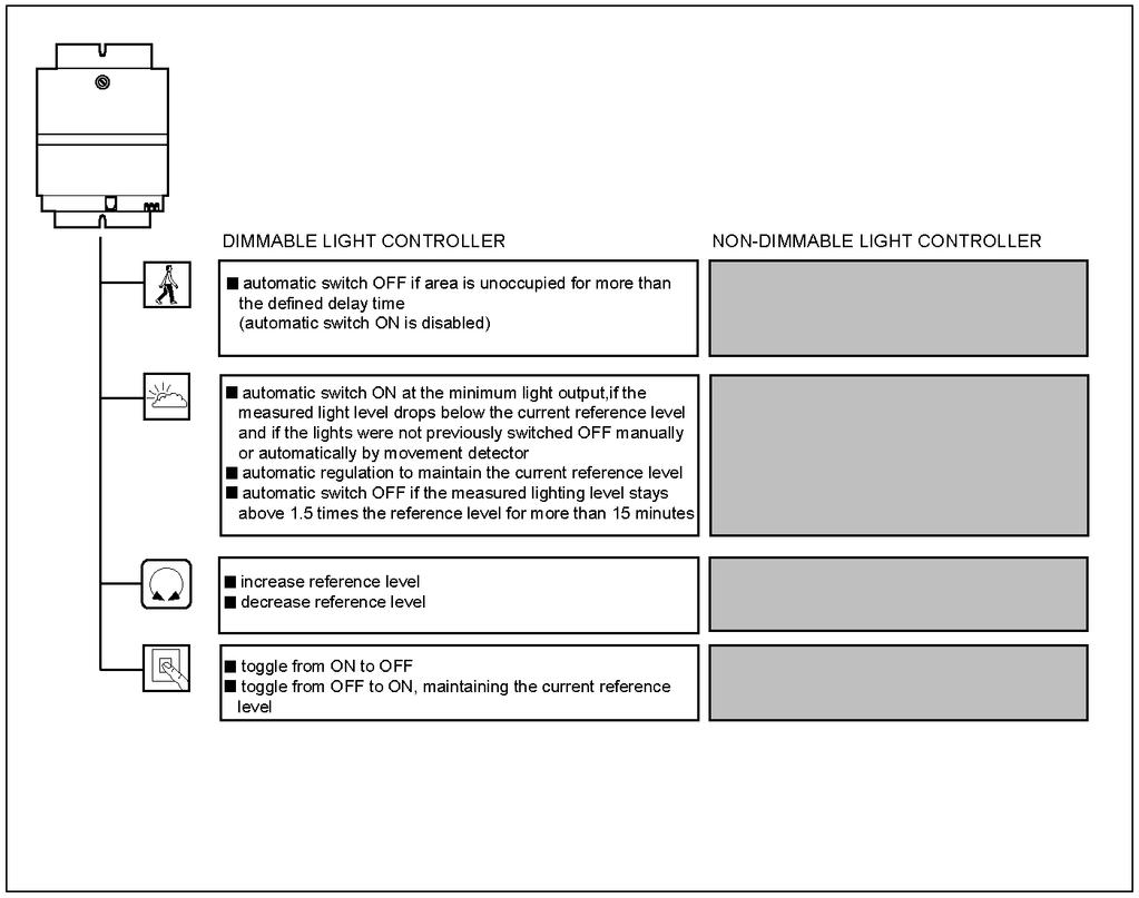
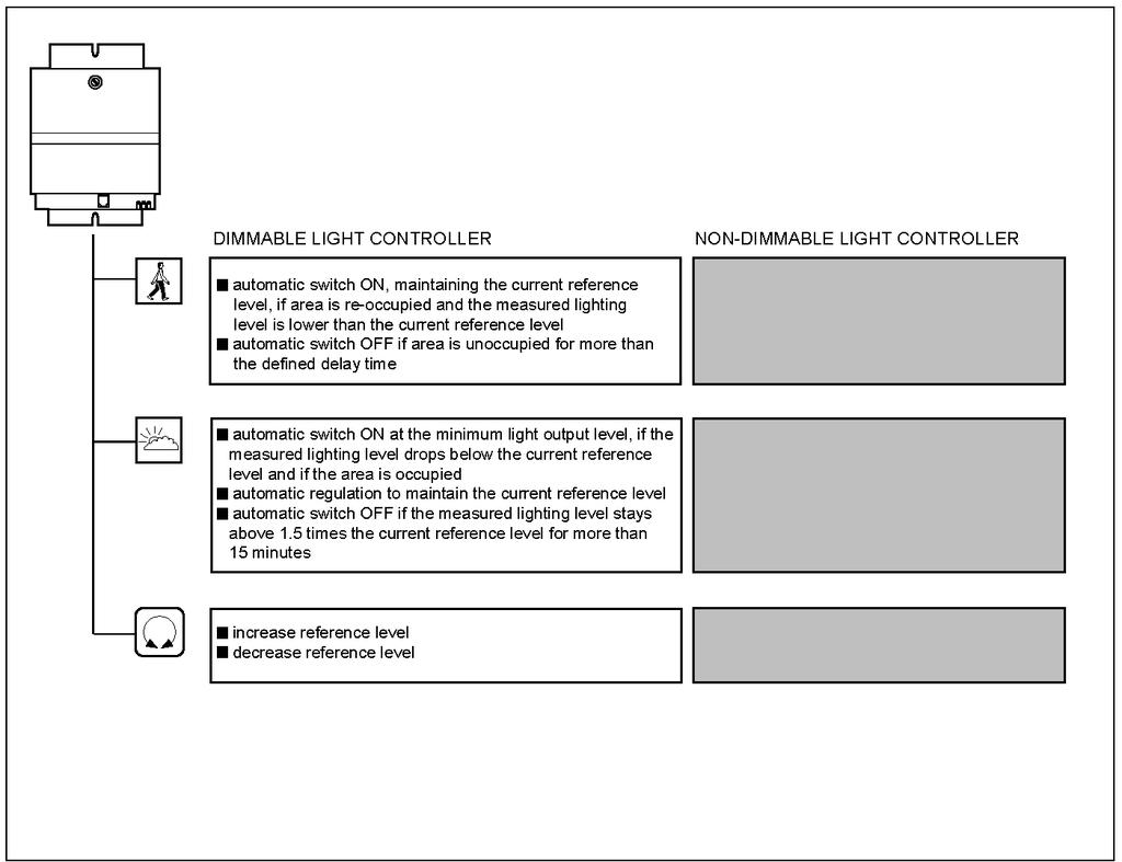
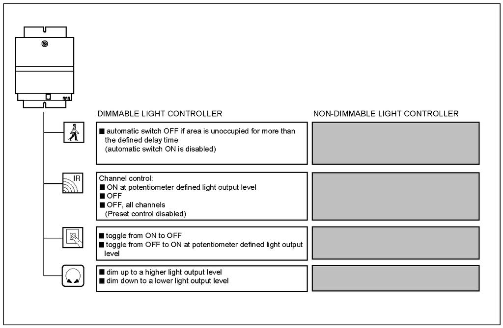
4 TRIOS training-manual Multi-functional push-button control. Switching, dimming and presets for lighting scenes using standard push-button switches connected to Trios via the push-button interface. Manual control with Energy saving Movement detector with infrared remote control. IR is used to recall stored lighting scenes and to switch and regulate individual luminaire groups. The movement detector ensures that the lights are automatically switched off when areas are unoccupied for longer than the defined delay time. Lights are not automatically switched on when areas are re-occupied. Light sensor combined with infrared remote control IR is used to set reference levels for constant lux and daylight linking applications without having to adjust the sensitivity of the light sensor. Lights are automatically regulated to maintain the selected lux level when daylight levels change and are automatically switched off when measured lux levels are too high. Lights are not switched on automatically when daylight levels drop below the defined reference level. Light sensor and movement detector with IR remote control. Lights are automatically regulated to maintain the IR remote control selected lux level and switched on or off when measured lux levels are too low or too high respectively. Lights automatically switch off when areas are unoccupied but cannot automatically switch on when reoccupied, i.e lights have to be switched on by IR remote control Hands-free control with Energy saving Light sensor and movement detector with potentiometer. The potentiometer is used to set the reference level for the light sensor. Lights are automatically switched and regulated to maintain the selected lux level. The movement detector automatically switches lights off when an area is unoccupied, and on when it is re-occupied.

5 TRIOS training-manual TRIOS SYSTEM OVERVIEW The range of multi-functional light controllers, sensors and potentiometers from Philips, the pushbutton switches from e.g. Busch & Jaeger and Merten, the special sensor cables and extension cables, interlink cables and branching connectors from Philips or other suppliers are the components that can be found in a Trios lighting control system. Sensors, push-button switches and potentiometer are connected to the light controller to obtain the desired lighting functionality. Sensor cables terminated with modular plugs at both ends and extension cables with modular plugs and sockets are used to bridge the distance between the sensor and light controller. Interlink cables terminated with modular plugs at both ends are used to link various Trios light controllers, and branching connectors are used when more sensors have to be connected to the light controller. All the Trios light controllers are designed to switch inductive, capacitive and resistive lighting loads upto 5A. The dimmable versions can regulate up to 150 luminaires simultaneously if they are fitted with Philips HF-Regulating ballasts for fluorescent lamps. Incandescent lamps, high-volt halogen lamps and low-volt halogen lamps can be regulated via the 100 VA electronic dimmers of Philips or via other suitable dimmers with a 1-10Vdc control voltage interface. Key to symbols 1. Multisensor LRI Infrared receiver IRR Movement detector LRM Light sensor LRL Sensor surface mounting plate 6. Sensor recessed mounting ring 7. Push-button interface LCU Trios light controller (DIN-rail version) LRC10x5 9. Trios light controller LRC10x0 10. Potentiometer LPS100/ Potentiometer LPS100/ Multi-purpose wall transmitter IRT Hand-held transmitter IRT8030
 and dimmable version (LRC1020 and LRC1025) with fixed lighting functions for standard solutions, and")

6 TRIOS training-manual Trios is an intelligent, multi-functional light controller that translates peripheral inputs into light switching and regulating commands via a functional control program. Light controllers are available in three functional versions; a non-dimmable (LRC1010 and LRC1015) and dimmable version (LRC1020 and LRC1025) with fixed lighting functions for standard solutions, and a dimmable version with programmable functions for tailor-made solutions (LRC1030 and LRC1035). As an additional feature, the LRC1030/1035 has two control outputs for the individual dimming of window side luminaries and corridor side luminaries in a room. The programmable control functions are defined by a personal computer through menu controlled programming software (the programming manual for the programmable light controller version is included in Appendix A). installations Housing To take account of the various installation practices, all three functional versions are available in an installer box housing for screw mounting against a ceiling or wall and in a DIN-rail housing for standard 35mm DIN rail mounting in mains distribution cabinets or similar. The installer box version has been designed for various types of cable gland options. Its front panel has four, 19mm wide slots with removable gates: 2 gates with open access holes for mains connections and 2 with knock-outs for the control voltage connections. The access holes are primarily dimensioned for standard PG 13.5 cable glands but the gates can also be removed for other cable access solutions (e.g. HAF 3525 gates with pull-relief or HAF 3529 gates for 19mm diameter pipes).
7 TRIOS training-manual
8 TRIOS training-manual Connecting peripherals The number of peripherals connected to a Trios light controller is limited to one potentiometer, one light sensor, three movement detectors, three IR receivers and three push-button interfaces for multi-functional push-buttons. Any combination is possible as long as the given maximum numbers are not exceeded. The number of push-button switches connected to one light controller is unlimited. Three-fold branching connectors (LCC8024) must be used when more than one sensor is connected to a light controller. The sensor cables can be extended by using one or more extension cables, which are available in 5m (LCC8012) and 20m lengths (LCC8013). Extension cables have modular plugs and sockets to simplify connections. The maximum distance between a light sensor and a light controller is 125 meter The maximum distance between a movement detector and a light controller is 125 meter. The maximum distance between a IR receiver and a light controller is 30 meter The sum of all sensor cabling must be less than 125m. The maximum allowable potentiometer cable length is 30m The maximum allowable cable length from a push-button to a controller is 125m. The figure shows how peripherals can be connected to a single light controller. Remark: The maximum cable length s in the drawing are different comparing to the text, the info in the text is OK! 1
9 TRIOS training-manual Interlinked Trios light controllers Infrared receivers, movement detectors and a light sensor can be connected to a group of linked light controllers to allow for the use of lighting scenes, or simply to increase the controlled lighting load. As shown in the diagram (fig2.4 a), each light controller is connected to the mains power supply, switches and regulates its own lighting load and receives the same sensor signals via the interlink cables. Up to five Trios lighting controllers can be linked together via their sensor input sockets with 1m long, LCC8011 interlink cables and LCC fold branching connectors. If interlink cables lengths are insufficient, sensor cable LCC8014 or extension cables can be used to increase the distance between the light controllers. Sensors can be connected to any available input socket within the group. The number of infrared receivers, movement detectors and light sensors that may be connected to a group of interlinked light controllers, is the same as for a single light controller. This also applies to the distance between the sensors and light controller. If more than two light controllers are interlinked, the allowable sum of cable lengths is reduced from 125m to 100m or 85m. Up to 50 light controllers (fig.2.4 b) can be connected to (no more than) one potentiometer so that large numbers of luminaries can be regulated simultaneously. Any number of light controllers can be connected to one or more push-button switches. A typical application could be conventional light control with multiple switch points in large industrial halls. The maximum cable length between a light controller and push-button switch or potentiometer may not be more than 125 m or 30 m respectively.
10 TRIOS training-manual Master/slave configurations If many luminaires have to be controlled by for example, infrared remote control and/or light sensor, the regulating output of the master light controller can be connected in parallel to the potentiometer inputs of up to 25 slave controllers. The slave controllers (dimmable versions only) pass the received control voltage directly to the regulating inputs of the ballasts. The slave controllers act as amplifiers to increase the number of simultaneously regulated luminaries. Since each slave controller can regulate up to 150 Philips HF ballasts (ETC/R or HFR range), a single master controller is therefore able to control a maximum of 3750 ballasts simultaneously. A typical application could be daylight regulation in large, glass-roofed livestock enclosures (e.g. chicken farms) containing a very large number of dimmable luminaries. A Trios master / slave configuration is only useful if the number of luminaires that have to be controlled simultaneously is larger than the maximum number of luminaires that can be controlled in a group of linked light controllers As shown in the diagram the slave controllers are switched by an external mains contactor. The lights connected to the slave controllers can only switch on after a power interruption if the embedded application software in each slave controller detects movement. Since movement detectors are not connected, an active movement detector signal must be simulated by other means. This can be done by short circuiting the movement detector pins of a telejack plug and connecting this plug to each slave controller s sensor input socket. The short circuit can be realised by interconnecting pins 2 and 6 of a telejack plug with an electrical wire. The external mains contactor can be switched by the master light controller or by other means. The type of peripherals connected to the master controller determines the obtained lighting functionality. The number and type of peripherals connected to the master controller and the allowable cable lengths, are the same as for a single light controller
11 TRIOS training-manual Switching lighting loads via external mains contactors Trios employs an ingenious switching method using a triac circuit in combination with a relay contact to ensure that any type of lighting load can be switched up to 5A without generating sparks or inrush-currents. In some applications, e.g. sports halls and industrial complexes, Trios must switch large lighting loads (> 5A) via high inductive external mains Contactors. Contactors can cause problems in Trios switching circuit when they have to be opened to switch lights off (closing the contactor is never a problem). When inductive loads (cos phi «0.5) are switched off, Trios switching circuit re-triggers the triac and prevents the external contactor from opening. The problem can be alleviated by either placing a small resistive load parallel to the external contactor (e.g. small lamp) or by simply adding a transient suppresser (i.e. a RC-unit or sparksuppresser ) over the switched output of Trios as shown in the diagram A suitable transient suppresser for most external contactors is one with a capacitor value of: C = 0.25µF and a resistor value range of: R = Ohm. Other types of transient suppressers can also be used but your choice depends on the contactor s specified coil consumption. If the contactor s coil consumption( needed to close the contactor) is higher than 50VA, a transient suppresser with a capacitor value of C = 0.1µF is sufficient, otherwise a higher capacitor is needed (e.g. 0.25µF). The resistor value must be larger or equal to 22 Ohm. Regulating lighting loads Dimmable Trios light controllers have a separate 1-10 V dc control interface to regulate the output level of a lighting load. Because lamps cannot be regulated directly, they have to be connected to Trios regulating output via dimmable ballasts or dimmers with a 1-10 V dc control interface. Philips regulating ballasts and dimmers have a standardised dim-curve which relates the light output level to the control voltage between 1 and 10 V dc (lighting levels increase with increasing control voltages). Trios control voltage may produce different lighting levels when dimmers and ballasts from other suppliers are used. Control interfaces have two polarity sensitive terminals (plus and minus) that are either current sinking (light controllers) or current sourcing (HF ballast and dimmers). Current sinking interfaces absorb the current generated by one or more current sourcing interfaces. The number of ballasts and/or dimmers that can be regulated simultaneously by a single dimmable light controller therefore depends on the specified current sourcing of each connected ballast or dimmer.
12 TRIOS training-manual Because Philips HF ballasts (ETC/R and HFR range) and dimmers (LRD8000 and 8010) source 0.15 ma and 0.5 ma respectively, a maximum of 160 ballasts or 50 dimmers can be regulated simultaneously by a Trios dimmable light controller, which sinks up to 25 ma. The programmable light controllers (LRC1030/1035) have two regulating outputs that can sink up to 20 ma each. Trios light controllers and Philips dimmers have a double (4kV) isolation barrier between their control interface and main parts. Philips HF regulating ballasts have a basic (2kV) barrier. This means that signal wire cables can be used to connect the control interfaces of Philips dimmers to the regulating output of Trios. For the connection of HF regulating ballasts to the regulating output of a Trios light controller, mains type of wiring must be used. In order to avoid interference, control cables must not be placed in the same cable duct compartment as the mains cables.
13 TRIOS training-manual Daylight linking Daylight linking can be divided into two principles: G Daylight switching G Daylight regulating Daylight switching (LRC1010/1015) Production halls and large warehouses often have windows on the roof to increase the contribution of daylight in working areas. The amount of natural light during the day is usually sufficient for some luminaires to remain off. In these applications, a light sensor and nondimmable Trios light controllers (LRC1010 or LRC1015) are ideal to automatically switch selected luminaires off when measured ambient lux levels are sufficiently high or on when they are too low. Luminaires in daylight switching application have non-dimmable HF ballasts and cannot maintain a constant lux level. As a result, lux levels change abruptly when Trios automatically switches the lights on and off. The daylight level at which Trios automatically switches lights on is defined by the reference level in Trios and by the sensitivity of the connected light sensor. Since the reference levels are fixed in non-dimmable light controllers, the only way to change the lux level at which Trios automatically switches lights on, is to change the factory adjusted sensitivity of the light sensor. As with daylight regulation, automatic switch on is only possible when movement detectors are connected to Trios. This is to prevent lights from automatically switching on at night when areas are unoccupied. It is important to note that it is not possible to use dimmable light controllers in daylight switching applications because their programmed switch-off levels are too low (1.5 x reference level). Daylight switching applications need relatively high switch-off levels to prevent ambient lighting levels from dropping below the default reference level immediately after switch off (lights will otherwise automatically switch back on). It is therefore essential to use non-dimmable Trios light controllers in daylight switching applications. They are programmed to automatically switch lights off if the measured ambient lighting level remains higher than 2.2 times the default reference level for more than 15 minutes
14 TRIOS training-manual Luminaires connected to non-dimmable light controllers switch on automatically when the light sensor s output signal drops below 4Vdc (= reference level) and off when the output signal is above 8.8Vdc (2.2 x reference level) for more than 15 minutes. The ambient lighting levels required to generate these control signals are determined by the light sensor s sensitivity. Example: In a daylight switching application with non-dimmable luminaires and light controllers, the light sensor s default sensitivity of 22mV/lux causes the lights to switch on automatically when the ambient lighting level drops below 600 lux. If the requirement for the application is that lights must switch on automatically when ambient lighting level drops below 500 lux which, in this example, is assumed to be equal to the installed lighting capacity, the following steps must be followed: 1. Create a lighting level equal to the new switch-on level of 500 lux. Since this is equal to the installed lighting capacity, it can only be obtained when the lights are switched on at night or when they are switched on during the day with closed curtains. When the ambient lighting level is 500 lux, the light sensor s LED indicator will not be at maximum brightness because the generated control voltage is lower than Trios reference level of 4Vdc (the light sensor s control signal drops below 4V dc when the measured light level drops from 600 lux to 500 lux 2. Change the light sensor s sensitivity so that it generates a control voltage of 4Vdc at 500 lux The sensitivity must be increased to decrease the automatic switch-on level from 600 lux to 500 This is done by turning the linear potentiometer clockwise until the LED indicator is fully on The potentiometer must be turned less than 180 at a time with a 5 second interval between each increment. If, after an increment, the LED indicator remains on (the control voltage is then above 4Vdc), the sensitivity must be reduced again by turning the potentiometer counter-clockwise in smaller increments. This process is repeated until the LED indicator just reaches its maximum brightness. Once the correct sensitivity is obtained, the lights will switch on automatically when ambient lighting levels drop below 500 lux (i.e. when the control signal drops below 4Vdc). If the ambient lighting level remains above 1100 lux (2.2 times the reference level = 8.8Vdc) for more than 15 minutes, Trios will switch the lights off automatically.
15 TRIOS training-manual NOTES: - If a light sensor plus a movement detector are connected to a Trios controller, lights can be switched on automatically when movement is detected and daylight levels are insufficiently high. - Automatic switch On is also possible if the light sensor is connected to the Trios controller (eventually combined with a potentiometer) and if the movement detector input has been short circuited.

16 TRIOS training-manual Example: The sensitivity of the light sensor is 22mV/lux and the average reflection coefficient of the area is 30%, the light sensor must measure reflected light below 182 lux (4000mVdc/(22mVdc)) or above 400 lux (8800mVdc/(22mVdc/lux)) before Trios can generate a switch-on or off command respectively The corresponding ambient lighting levels in the area are 600 lux (182lux/0.3) and 1320 lux (400lux/0.3) respectively. If the automatic switch-on level is too high and should instead be 500 lux (e.g. the installed capacity of the lighting installation), the sensitivity of the light sensor must be increased. Lux levels can only be adjusted by potentiometer or IR remote control in daylight regulation or constant lux applications (with dimmable light controllers and luminaires). In daylight switching applications with non-dimmable light controllers (e.g. industrial halls), the automatic switching level can only be changed by changing the sensitivity of the light sensor.
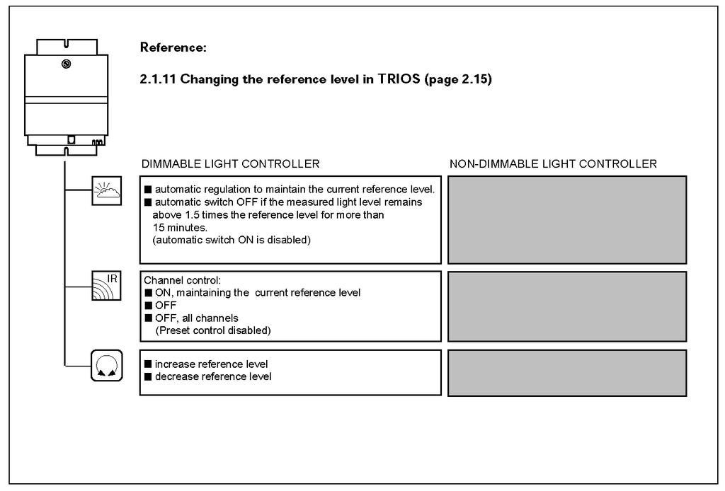
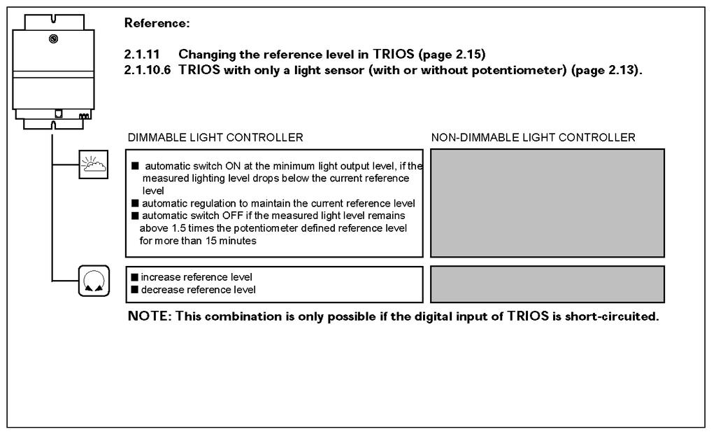
17 TRIOS training-manual Although it is possible to calculate the required sensitivity to obtain 500 lux (see formulas above), it is impossible to find the corresponding setting for the potentiometer without additional aids. The light sensor s LED indicator must therefore be used when sensitivities are changed. Daylight regulation and Constant lux (1020/25;1030/35) Trios becomes very powerful when the light sensor is combined with manual light control in multitask areas like open-plan offices, schools and sporting facilities. With Trios, any lighting level can be obtained by potentiometer or IR remote control without interrupting automatic light control. The selected lighting level automatically creates a new reference level for Trios so that energy is saved for all lighting levels. The light sensor is used for two types of indoor applications; - a daylight regulation application where artificial light control is directly linked to the available daylight, and - a constant lux application where an over-installed capacity is eliminated and a constant lux level is maintained throughout the lighting installation s life-time. Daylight regulation: A dimmable light controller automatically reduces the artificial lighting level when daylight levels increase and/or automatically switches them off when daylight levels are sufficiently high. The purpose of daylight regulation is to maintain a defined lux level (reference level) in an area for optimal working conditions. When the defined lux level cannot be maintained due to increasing daylight levels, Trios will automatically switch the lights off if the measured ambient lighting level is 1.5 times higher than the reference level for at least 15 minutes Since the light sensor s output signal is limited to 10Vdc, it is possible that Trios cannot generate a switch-off command if its switch-off level is higher than 10Vdc i.e. if its reference level is higher than 6.7Vdc. In this case, the lights will remain at their minimum output level and will not switch off automatically. Constant Lux level: A light sensor can also be used to reduce the energy consumption of initially over-designed lighting installations. When it is combined with a dimmable light controller, the over-design capacity is eliminated by obtaining the desired lux level immediately after installation. As the installation s output deteriorates due to lamp ageing, Trios automatically increases the lighting level to maintain the desired lux level. Constant lux applications can only be realised with dimmable light controllers and dimmable ballasts. The lux level that is required for the application can be defined by potentiometer, IR remote control, RC5 encoded push-button switches or by changing the sensitivity of the light sensor.
18 TRIOS training-manual Changing the reference level in Trios. Trios controller LRC1010 The Trios-reference level (fixed 4V) and the light sensor sensitivity setting together define at which lux level the lights will switch ON. The lights will switch OFF at 2.2 times the reference level (=2.2 x 4 Volt = 8.8Volt) Since the reference level is fixed, the only possibility to change the level at which Trios will switch the lights ON and OFF is to change the light sensor sensitivity. (see paragraph daylight switching). Trios controller 1020/25; 1030/35 Also in these controllers the reference level and the light sensor sensitivity setting together define at what lux level lights will switch ON. The lights will switch OFF at 1,5 times the reference level. The reference level in the dimmable controller is not fixed, but it can be changed by IR commands or with a potentiometer. If the controllers default reference level (=4Volt) does not produce correct lux levels, it can be changed with IR transmitters, RC5 pushbutton interfaces or with a potentiometer. Artificial lights are simply dimmed up or down until the desired lux levels are reached. This desired lux level, which is a combination of artificial and daylight, is reflected back to the light sensor. The sensor s output value is the new (temporary) reference level. (The value will be stored as the new temporary reference level 5 seconds after the last IR command was given.) This temporary reference level remains valid until a new IR command or potentiometer adjustment is generated. The initial light sensor sensitivity (factory adjustment) has to correspond to the applications installed light level, other wise it has to be adjusted to adapt to this level.
19 TRIOS training-manual It is possible to store 4 preset light-levels in the Trios (dimmable)controller. This can be done with the IRT8030 handheld transmitter. To recall these presets, the IRT8030 or the IRT8050 wall transmitter can be used. NOTE: If you would like to store one of Trios four preset memories, the store command should not be executed on the IRT8030 transmitter earlier than five seconds after the new reference level has been selected (by the channel keys). Otherwise an incorrect reference level will be stored.
20 TRIOS training-manual Changing the reference level by potentiometer When a LPS 100 potentiometer is combined with a light sensor, the reference level in Trios is always equal to the potentiometer s control voltage. Slow light reactions when reference levels are changed. When reference levels are changed by adjusting the potentiometer, the balance between the light sensor s output signal (A) and the potentiometer s selected reference level (B) is lost temporarily. Trios control program corrects this imbalance by regulating the lights up or down until the balance is restored (C). It takes some time to change lux levels with a potentiometer because the result is unknown immediately after each adjustment. The lux level corresponding to the potentiometer adjustment is only known once Trios restores the balance. Due to these reaction delay times, a potentiometer in combination with a light sensor should not be used in applications where a user is able to adjust lux levels. Potentiometers are however, very useful when the constant lux level in an application must be fixed during normal conditions and when it has to be easily changed if working conditions change. If for example, 500 lux must be maintained in an administration office, a dimmable light controller and light sensor can be used together with push-buttons for manual switching and a potentiometer for defining constant lux levels. To prevent users from changing reference levels, the potentiometer should be placed outside the office within easy reach (e.g. in an installation cabinet). In this type of application, a potentiometer is ideal to obtain the required lux level quickly and accurately during commissioning without having to climb a ladder to change the light sensor s sensitivity.
21 TRIOS training-manual IR remote control for commissioning and for light control The light controller s reference level is continuously updated when IR remote control is used. This can be done by recalling presets or by dimming. Since the reaction to IR commands are immediate, the desired (reference) lux level is obtained quickly and efficiently. IR remote control is therefore an ideal commissioning tool for installers or facility managers who use it to define or adapt an application s constant lux level. If this lux level is subsequently stored in the preset memory of Trios (using the IRT8030 hand transmitter), a user can switch the lights with the IRT8050 wall transmitter (in four different presets) without being able to change the pre-defined lux levels. If the user is permitted to change lux levels, the IRT8030 hand transmitter or RC5-encoded push-button switches can be used for maximum flexibility in light control. Reference levels can be defined at any time of day The power of this concept is that a reference level can be defined and stored in Trios at any time of day without worrying about the effect of daylight levels. Since reference levels are derived from light sensor measurements (= daylight level + artificial light level) immediately prior to storing, a stored reference level will always obtain the desired lux level on a working surface. Recalling preset reference levels When a transmitter or RC5-encoded push-button switch is used to recall preset 1 then the associated artificial light output is depending on the amount of daylight at the moment of recalling. Trios control program automatically selects the correct artificial light output based on the inputs of the light sensor. If for example 500 lux is stored in preset 1, the associated artificial light output is much lower during daytime than at night (when it is dark). Working principal of Trios 1030/35. Preset 1. If the reference level stored under preset 1 is not sufficient (e.g. 500 lux), lights can be dimmed up or down until the desired light level is reached (e.g. 750 lux). This is then the new reference level (daylight + artificial light) at which the artificial lights will regulate. If a movement detector is installed and lights switch off because no movement is detected; the lights will automatically switch back on in preset 1 if movement is detected again. This means that daylight regulation is active. If lights are switched off manually, they can only be switched back on manually by pressing one of the four preset buttons. Preset 2 Preset 3 Preset 4 are adjustable light level presets without daylight regulation possibilities. E.g. if preset 2 is 500 lux and daylight is increasing the artificial light output remains at 500 lux, unless the lights are dimmed manually. This means there is not automatic daylight regulation. If daylight regulation is required preset 1 has to be selected and lights will regulate to the reference level stored under preset 1.
22 TRIOS training-manual IRT 8030 Infrared remote control The advantage of IR remote control from an installation point of view is that vertical switching wires to wall switches are no longer needed. This reduces the initial electrical installation costs and eliminates future re-wiring costs when partition walls are moved. The user is offered both flexibility and comfort; lights can be switched and regulated from any point in the room, groups of luminaires can be controlled independently in both open-plan and modular offices and predefined lighting scenes can be recalled. Functionality Four presets can be selected with the four large keys on the front of the transmitter. The fifth large key is the all off command. This transmitter has five different infrared channels for individual control of a maximum of five different control circuits. As this function is normally required only during installation or adaptation of the lighting installation, the necessary keys are located behind a hinged cover. A preferred setting of the lights can be stored in the memory of the controller(s). For incidental changes of system parameters, the transmitter can be switched temporarily into a teach mode. The IRT8030 can then be used as a Trios programming tool, thus offering the same (programming) functionality as the Trios programming tool IRT1090 and as included in the remote control transmitter IRT8050. For an overview of the key allocation refer to figure 1: key functions of the IRT8030
23 TRIOS training-manual For an overview of the key allocation in teach mode refer to figure 2: key functions of the IRT8030 in teach mode. Operating instructions General information The allocation of keys is such that the most common functions can be operated with the large upper keys and the less common functions with the keys under the hinged cover. Dimming and switching of individual control circuits and the programming functions in teach mode require a two-step operation: First the required channel or parameter must be selected, then the required operation can be executed or the selected value entered. The following paragraphs give a short description of the various control functions. Obviously these descriptions are only relevant provided that this function is supported by the corresponding control system. For details on specific functions please refer to the documentation on the relevant control system. Selecting presets (light scenes) One out of four presets can be selected directly using one of the four large keys on the front of the transmitter. Lights can be switched off simultaneously with the fifth large key. Controlling individual lighting control circuits in Helio and Trios First the required channel must be selected, then the required operation can be executed. Channel selection is achieved with the Select key. An LED indicates the selected channel. When the Select key is momentarily pressed (less than 1/2 sec.) the led shows the (last) selected channel. When the key is pressed continuously or repeatedly, the next channels are selected. This action can be continued or repeated until the required channel has been selected. If no further keys are pressed the LED s stay on during 5 seconds after the last key release.
24 TRIOS training-manual With the "#I" and "$O keys the selected channel can be switched and /or regulated, as allowed by the corresponding controller(s). During the actual transmission of infrared signals, the LED flashes for verification of the selected channel. After transmission the LED is switched off. Programming presets The procedure to be followed is: 1. adjust individual control circuits as described before 2. press the store key 3. press the wanted preset key Recall installer presets At any time the user can revert to the pre-programmed presets as set by the installer, by pressing the Recall key. Programming Operational Mode, Group Address and Channel Address For programming the group, or channel, addresses or the operational mode of a controller, the transmitter must be set in the teach mode. This is done by pressing the "#I" and "$O keys (under the cover) simultaneously until (after about 3 seconds) a flashing LED (2 flashes per second) indicates the teach mode. The functions of the keys in teach mode are shown in figure 2. First the parameter to be programmed (group, channel or mode) must be selected, and then the required value can be entered. Parameter selection is done with the Select key. An LED indicates the selected parameter. When the Select key is momentarily pressed (less than 1/2 sec.) the led shows the (last) selected parameter. When the key is pressed continuously or repeatedly, the next parameters are selected. This action can be continued or repeated until the required parameter has been selected. If no further keys are pressed the LED s stay on during 5 seconds after the last key release. The value required is programmed by pressing the appropriate upper key (0-9 / A-G). The transmitter sends the codes that set the appropriate address or mode of the controller. During the transmission of the programming instructions, the infrared indicator LED will flash rapidly. When finished it returns to slow flashing. Also the function indicator LED will flash, thus showing the actual function. After programming is completed, the transmitter can be reset to normal operation by pressing the "#I" and "$O keys again until the LED s will switch off. The transmitter will revert to normal operation automatically 1 minute after the last key press. NOTES: 1. When transmitting in teach mode, the infrared radiation pattern of the IRT8030 is reduced to a narrow beam, in order to achieve selective programming of luminaires or controllers. Therefore the transmitter must be pointed directly at the receiver and the distance from transmitter to receiver must be less than 3 meters. (See figure 3) 2. All commands of the Trios teaching mode are transmitted in the general group, in order to assure proper reaction regardless the group address of Trios. IR channel addresses It is important in some IR remote control applications that a single transmitter is used to control several clusters of luminaires independently. In a large, multi-task office for example, the luminaires along a window, above a desk and above a meeting table have to be controlled separately to obtain the required lighting level for a specific task. This is done by connecting each luminaire cluster to its own Trios light controller and by giving each light controller a channel address. The channel control keys on the transmitter can then be used to control each luminaire cluster separately. Maximum 5 different addresses are possible.

25 TRIOS training-manual IR group addresses If IR remote control is used in multi-user areas like open plan offices, it is essential to limit light control to defined areas. This is done by giving Trios light controllers in each sector a group address. A transmitter with address A will only control the luminaries connected to light controllers with the same address and will not interfere with light controllers with other address numbers. A maximum of 7 groups (each having a maximum of 5 channels) is possible. The figure gives a typical example of an open-plan office sub-divided into seven sections with independent light control in each section. Using the IR functions, lighting scenes can be customised for different tasks in each office section Transmitters also have a General Group address (ALL GROUPS) enabling them to control all the light controllers irrespective of their group address. Transmitters set to the General address are especially useful for night cleaning or night patrol purposes when lights anywhere in the building have to be controlled by a single person. The Trios teach mode is used to define the channel and group address in the light controllers by IR remote control. Presets Lighting levels that are needed more often can be stored in the light controller s preset memory with a transmitter. The transmitters preset keys are used to recall predefined lighting levels ( single-channel applications) or predefined lighting scenes ( multi-channel applications) quickly and efficiently when lights have to be adapted for specific tasks. The figure shows an example of four preset lighting levels stored in a light controller with a channel 1 address.

.")
26 TRIOS training-manual Changing channel and group addresses of Trios light controllers The Figure illustrates how to change the channel and group addresses of light controllers in an office with multi-channel control. Changing the channel address If the light controllers are interlinked, as in this example, first disconnect the interlink cables. Connect an infrared receiver to the controller that needs to be addressed. To change the channel address, point the transmitter to the IR receiver and press the required channel address key (1-5). Trios will confirm a successful programming action by a double state toggle of the output. Repeat this procedure for all light controllers that need to be addressed. Finally re-connect the interlink cable and the sensor. Changing the group address. The group addresses of the light controllers have to be set to group address (B). If the light controllers are interlinked and connected to an infrared receiver, the group address of all controllers can be changed at ones. To change the Trios light controllers group address, point the Trios programming tool towards the IR receiver and press the required group address key (A - G). Trios will confirm a successful programming action by a double state toggle of the output. Communication between programming tool and light controller. In order to communicate with each other, the light controller and the Trios programming tool must have the same group address. Normally the programming tool is (factory)set to the general group. Therefore all Trios controllers will react (irrespective of its own group address A-G). The reaction of Trios can be tested by using the ALL OFF and Preset 1 key on the programming tool.

27 TRIOS training-manual Functions with combined peripherals

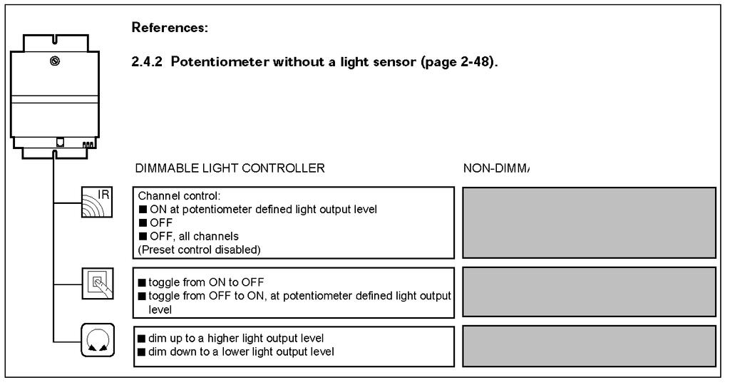
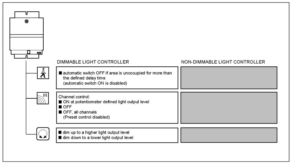
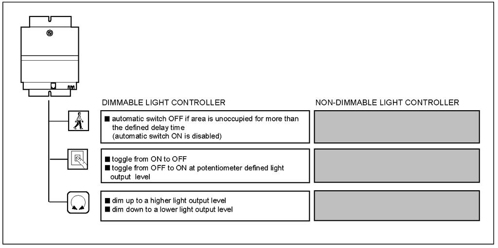
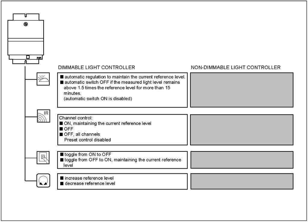
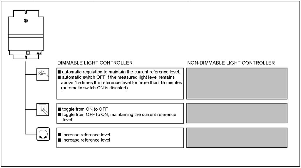
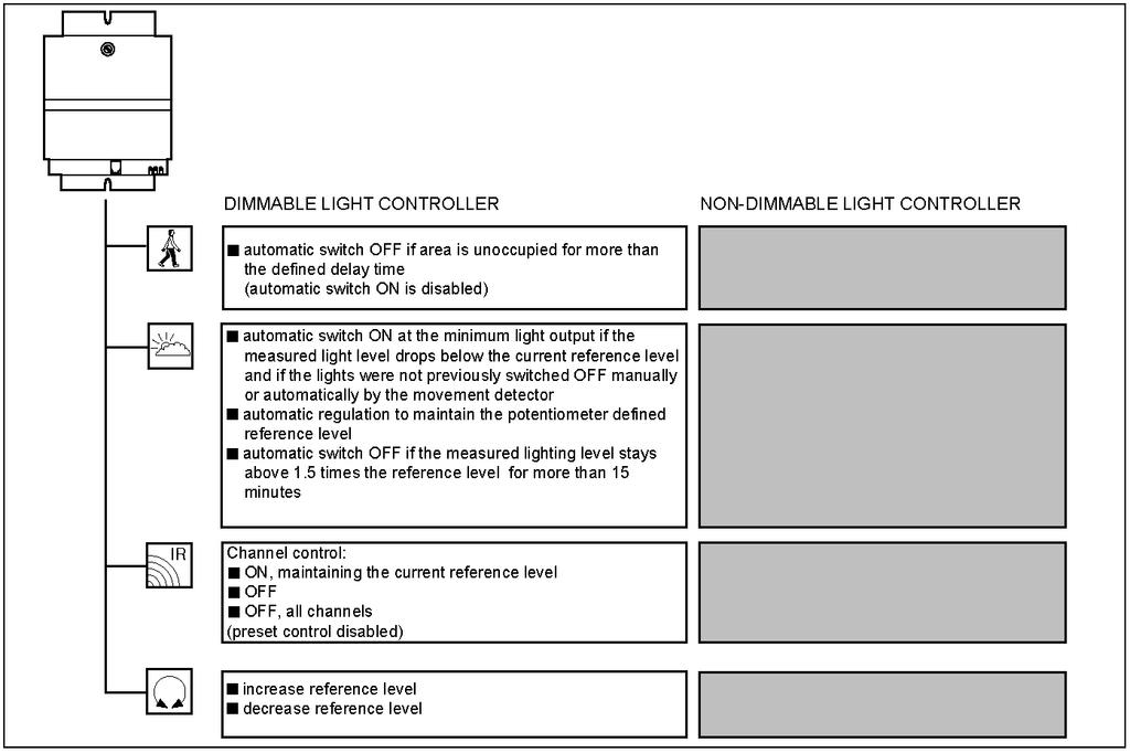
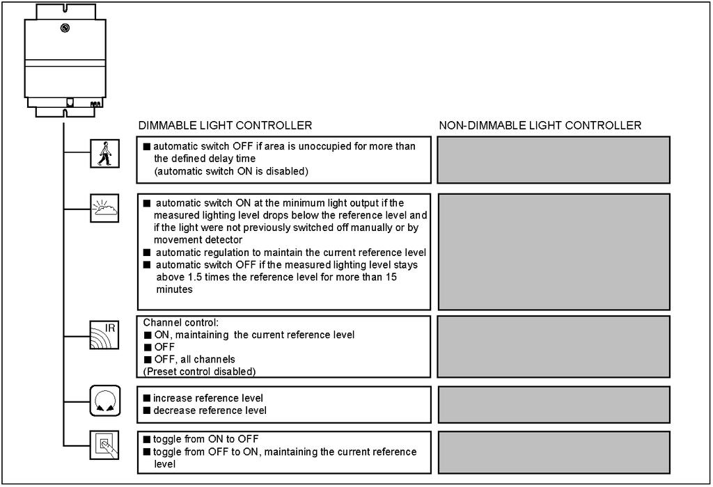
28 TRIOS training-manual Manual / Remote control There are four manual control possibilities with TRIOS light controllers: - IR remote control with IRR8124 receivers and IRT8030/IRT8050 transmitters, - multi-functional control with push-button switches and push-button interface, - basic toggle switching with push-button switches and - dimming with LPS100 potentiometers. The manual control options can be used separately or combined with other types of sensors, like movement detectors, light-sensors and potentiometers. In the following sections a detailed description is given of the functionality of all possible sensor combinations. Since IR remote control and RC5 encoded push-button switching are functionally the same, no distinction is made between the two when they are discussed in combination with other peripherals. The push-button interface however has four extra toggle functions
29 TRIOS training-manual
30 TRIOS training-manual
31 TRIOS training-manual
32 TRIOS training-manual
33 TRIOS training-manual
34 TRIOS training-manual
35 TRIOS training-manual
36 TRIOS training-manual
37 TRIOS training-manual
38 TRIOS training-manual
39 TRIOS training-manual
40 TRIOS training-manual
41 TRIOS training-manual Trios controller with only a light-sensor, or a light-sensor in combination with a potentiometer If the peripherals connected to a Trios light-controller consists of only a light sensor, or a light sensor in combination with a potentiometer, special care must be taken. The light controller will not switch On if only a light sensor is connected. Therefore the movement detector input (pin 2 and 6 of the telejack plug) has to be short circuit. 2 and 6 shortcircuit
DALI SPECIFICATION GUIDE
 DALI SPECIFICATION GUIDE Page 2/3 contents Page 1. INTRODUCTION 6 2. DALI - THE STANDARD 6 2.1. Industry standard 6 2.2. Light control 6 2.3. Digital control 7 2.4. Switching in the electronic ballast
Connections, displays and operating elements C D E G H. Installing the control unit
 1 2 3 GB Control unit 0-10 V REG-K/3-gang with manual mode Operating instructions Art. no. MTN646991 ¼ DANGER Risk of fatal injury from electrical current. All work on the device should only be carried
Stellar Panelboard Dimming Systems
 create a new dimension in lighting control. While lighting systems consume energy, Stellar dimming panels conserve and redirect energy into the atmosphere of your facility. The panel s universal dimmers
Ceiling PIR HS presence detector 1-10V, low temperature. PIR Sensor. IR Receiver. Light Level Sensor. Status LEDs. IR Receiver
 Product Guide EBDHS-AD-LT30 Ceiling PIR HS presence detector 1-10V, low temperature Overview The EBDHS-AD-LT30 PIR (passive infrared) presence detector provides automatic control of lighting loads with
Ceiling PIR presence detector DALI / DSI dimming. PIR Sensor. IR Receiver. Light Level Sensor. Status LEDs. PIR Sensor.
 Product Guide EBDSM-DD Ceiling PIR presence detector DALI / DSI dimming Overview The EBDSM-DD PIR (passive infrared) presence detector provides automatic control of lighting loads with optional manual
SMART BASIC BASIC-IR DAYLIGHT
 LUXMATE Lighting Control System LUXMATE. The ing system for maximum quality and dimming convenience. SMART BASIC BASIC-IR DAYLIGHT The art of modern technology lies in making complicated things simple.
EBDHS-DD-LT30. Ceiling PIR HS presence detector DALI / DSI, low temperature. Product Guide. Overview. Features
 EBDHS-DD-LT30 Product Guide Ceiling PIR HS presence detector DALI / DSI, low temperature Overview The EBDHS-DD-LT30 PIR (passive infrared) presence detector provides automatic control of lighting loads
High bay PIR presence detector 1-10V dimming. PIR Sensor. IR Receiver. Light Level Sensor. Status LEDs. IR Receiver
 Product Guide EBDSPIR-HB-AD High bay PIR presence detector 1-10V dimming Overview The EBDSPIR-HB-AD PIR (passive infrared) presence detector provides automatic control of lighting loads with optional manual
Description of the application programme for KNX occupancy detectors version 3.1
 Contents 1. General...1 1.1 Basics for the KNX/EIB BUS...1 1.2 Application versions...1 1.2 Application versions Switchgear application Version 3.1: BEG_SWI_HKL_V3.1 Part numbers: 1.3 Symbols used...1
MWS5. Miniature Microwave Presence Detector (standalone) Product Guide. Overview. Features
 Product Guide. Overview. Features") Product Guide MWS5 Miniature Microwave Presence Detector (standalone) Overview The MWS5 series of miniature microwave presence detectors provide automatic control of lighting loads with optional manual
Product Guide MWS5 Miniature Microwave Presence Detector (standalone) Overview The MWS5 series of miniature microwave presence detectors provide automatic control of lighting loads with optional manual
Ceiling Microwave presence detector - DALI / DSI 12-24V AC/DC. Microwave Sensor. IR Receiver. Light Level Sensor. Status LEDs.
 MWS6-DD-LV Product Guide Ceiling Microwave presence detector - DALI / DSI 12-24V AC/DC Overview The MWS6-DD-LV microwave presence detector provides automatic control of lighting loads with optional manual
High bay PIR presence detector DALI / DSI dimming. PIR Sensor. IR Receiver. Light Level Sensor. Status LEDs. IR Receiver
 EBDSPIR-HB-DD Product Guide High bay PIR presence detector DALI / DSI dimming Overview The EBDSPIR-HB-DD PIR (passive infrared) presence detector provides automatic control of lighting loads with optional
Product Guide. Ceiling microwave presence detector DALI / DSI. Microwave Sensor. IR Receiver. Light Level Sensor. Status LEDs.
 MPAD-C-DALI-230V Product Guide Ceiling microwave presence detector DALI / DSI Overview The MPAD-C-DALI-230V microwave presence detector provides automatic control of lighting loads with optional manual
Product Guide. Ceiling PIR HS presence detector DALI / DSI dimming. PIR Sensor. IR Receiver. Light Level Sensor. Status LEDs.
 PPAD-C-HB-DALI-230V Product Guide Ceiling PIR HS presence detector DALI / DSI dimming Overview The PPAD-C-HB-DALI-230V PIR (passive infrared) presence detector provides automatic control of lighting loads
Use of the application program
 Contents overview Use of the application program Use of the application program 1 1. Functional description 2 Switching on / off 2 Dimming brighter / darker 2 Dimming value (8 bit) 3 Status Switching (1
KNX/EIB - Product database - Application description
 KNX/EIB - Product database - pplication description Theben HTS KNX/EIB Product Database V3.2 for Theben HTS presence detectors ECO-IR 360EIB-C ECO-IR 180EIB-C ECO-IR DUL-EIB compact office EIB compact
3. Proper use. 4. Function. 1. Product characteristics. 2. Safety. Function description. Channel A light. Motion detector
 307021 3. Proper use EN Motion detector themova P360-100 UP WH 1030600 themova P360-100 UP GR 1030601 The motion detector is intended for interior. The motion detector is eclusively intended for the use
, ,
 796-2028, 796-2021, 796-2025 Batten mount PIR detectors Overview This series of miniature PIR (passive infrared) presence detectors provide automatic control of lighting loads with optional manual control
PIR/INT & PIR/INT-D. Batten mount PIR detectors. Product Guide. Overview. Features
 Product Guide PIR/INT & PIR/INT-D Batten mount PIR detectors Overview The PIR/INT & PIR/INT-D miniature PIR (passive infrared) presence detectors provide automatic control of lighting loads with optional
Motion detector themova P360 KNX UP WH themova P360 KNX UP GR
 307079 EN Motion detector themova P360 KNX UP WH 1039600 themova P360 KNX UP GR 1039601 1. Product characteristics 4 2. Safety 5 3. Proper use 6 4. Function 6 5. Detection area 10 6. Installation 13 7.
B.E.G. LUXOMAT KNX-OCCUPANCY DETECTOR
 B.E.G. LUXOMAT KNX-OCCUPANCY DETECTOR GB Contents 1. GENERAL 1 1.1 KNX bus basics 1 1.2. Overview 1 1.3 Symbols 1 2. OCCUPANCY DETECTOR BASICS 2-3 2.1 Introduction 2 2.2 Motion detection with the B.E.G.
User Manual 120/240/300 Outdoor Motion Detector
 User Manual 120/240/300 Outdoor Motion Detector Swiss Garde 4000 Warning! - Any work on the main power supply must only be completed by trained specialists. - The product must be installed in accordance
Ceiling PIR HS presence detector. Product Guide. Overview. Features
 Product Guide 796-2047 Ceiling PIR HS presence detector Overview The 796-2047 (passive infrared) presence detector provides automatic control of lighting loads with optional manual control. This is a high
HF Motion Sensor Introduction
 HF Motion Sensor Introduction Completely built-in the lighting fixture, the motion sensor utilizes Doppler principle and RADAR technology to detect moving objects at certain speed & reflection surface,
Integrated PIR detectors
 EBMINT - Product Guide Integrated PIR detectors Overview The EBMINT series of miniature PIR (passive infrared) presence detectors provide automatic control of lighting loads with optional manual control
EBMPIR-MB. Batten mount PIR detectors. Product Guide. Overview. Features
 Product Guide EBMPIR-MB Batten mount PIR detectors Overview The EBMPIR-MB series of miniature PIR (passive infrared) presence detectors provide automatic control of lighting loads with optional manual
Digital Addressable Lighting Interface
 Digital Addressable Lighting Interface Who started DALI? It is supported by major manufacturers of ballasts Initially promoted by: And now including: BAG, Erco, Insta, Johnson controls, Magnetek, FCS lighting,
Product and Applications Description
 Product and Applications Description The presence detector with a sensing range of 360 allows the automatic execution of control functions in the electrical system by detecting movements. For example,
Tebis application software
 5 Tebis application software STCC530E 2-channel presence detector 360 A faire Product reference Description TP device RF devices TCC530E Bi-zone presence detector TCC530E Output module: Dimmer Loads connected
ABOUT THIS DOCUMENT AND THE DOCUMENT STRUCTURE WE USE
 ABOUT THIS DOCUMENT AND THE DOCUMENT STRUCTURE WE USE isocket Smart Relay is a complex Smart House system which is installed in the fuse cabinet (electric cabinet) in the house. We therefore assume that
Ceiling Microwave presence detector - DALI / DSI 12-24V AC/DC. Microwave Sensor. IR Receiver. Light Level Sensor. Status LEDs.
 MWS3A-DD-LV Product Guide Ceiling Microwave presence detector - DALI / DSI 12-24V AC/DC Overview The MWS3A-DD-LV microwave presence detector provides automatic control of lighting loads with optional manual
PRESENCE DETECTOR. PD-C360i/8 mini KNX PD-C360i/12 mini KNX / 13 7 REMOTE CONTROL PRESENCE DETECTOR
 In the Master function, the remote control entries will be acknowledged as follows: acknowledged 3 x with the red LED In the Slave function, each detection is acknowledged 2 x with the green LED. NOTE:
solar Tilbehør Lyssensorer Minilux Sensor (lyssensor) type med klemmetilslutning for udendørs montage
 type med klemmetilslutning for udendørs montage") Tilbehør Lyser Minilux Sensor (lys) type 43-193 med klemmetilslutning for udendørs montage Klemmerækketilslutning Tæthedsgrad IP 54 Lux-område 2-200 lux Minilux Sensor 43-193 er en lys, som dækker over
Tilbehør Lyser Minilux Sensor (lys) type 43-193 med klemmetilslutning for udendørs montage Klemmerækketilslutning Tæthedsgrad IP 54 Lux-område 2-200 lux Minilux Sensor 43-193 er en lys, som dækker over
EBMHS (standard & slim-line PSU)
") Product Guide EBMHS (standard & slim-line PSU) Miniature HS PIR Presence Detector (luminaire fitting) Overview The EBMHS series of miniature PIR (passive infrared) presence detectors provide automatic
Product Guide EBMHS (standard & slim-line PSU) Miniature HS PIR Presence Detector (luminaire fitting) Overview The EBMHS series of miniature PIR (passive infrared) presence detectors provide automatic
GE Lighting. Lighting Controls. DALI Digital Lighting Controls
 GE ighting ighting Controls I Digital ighting Controls the I Protocol Multi-functional control of I-ready GE uminaires 1-1 to I converters available for analogue luminaires I CB Type 2 - complete programmable
SWITCHLITE MRE DDM ADJ
 96239889 SWITCHLITE MRE DDM ADJ Front features Mounting Bezel Back features Retaining Spring Power Input & Switched Output Connector (Channel 1) Sensor Lens which covers... Microwave Sensor IR Receiver
1. Product characteristics 4 2. Safety 5 3. Proper use 5 4. Operation 6
 307214 1103107701 EN Presence detector theronda S360-101 DE WH 2080565 theronda S360-101 DE GR 2080566 theronda S360-101 AP WH 2080555 theronda S360-101 AP GR 2080556 1. Product characteristics 4 2. Safety
Product Guide. Ceiling microwave presence detector DALI / DSI. Microwave Sensor. IR Receiver. Light Level Sensor. Status LEDs.
 MPAD-C-A-DALI-230V Product Guide Ceiling microwave presence detector DALI / DSI Overview The MPAD-C-A-DALI-230V microwave presence detector provides automatic control of lighting loads with optional manual
FR-A180 FR-A360. Occupancy detector. Use
 5 488 Occupancy detector with daylight sensor Occupancy detector with integral daylight sensor for demand-based control of HVAC systems and lighting. Adjustable switch-on and switch-off delay Adjustable
Devices for Special Applications
 Overview AP 2/11 UP 2/12 N 26/02 UP 28/11 UP 28/21 N 342 AP24/02 GE 22 GE 23 GE 24 UP 2 AP 2 Control Integrated constant light level control 1-channel 3-channel -- -- -- 1-channel -- -- 1-channel -- 1-channel
SENSA MRE DDM MR
 96239831 SENSA MRE DDM MR Contents Section Contents Page 1 Dimensional information 1 2 Description and operation 2 3 Wiring and fixing 3 4 Programming 6 5 Wiring diagrams 8 6 Detection pattern diagrams
2. Safety. 1. Product characteristics. 3. Proper use. 4. Operation. Function description. Presence detector
 EN Presence detector theprema P360-101 E UP WH 2070105 theprema P360-101 E UP GR 2070106 1. Product characteristics 307175 1103087101 Passive infrared presence detector for ceiling installation Square
PSC-ID-x-CM Series Ceiling Mount Occupancy Sensor
 TECHNICAL SPECIFICATIONS PSC-ID-x-CM Series Ceiling Mount Occupancy Sensor Basic Features Line voltage version: 120-277VAC, 60Hz Low voltage version: 24VDC, requires separate class 2 power supply PIR sensor
OVEN INDUSTRIES, INC.
 OVEN INDUSTRIES, INC. OPERATING MANUAL Model 5C7-252 TEMPERATURE CONTROLLER With PLC Inputs Introduction Thank you for purchasing our controller. The Model 5C7-252 is an exceptionally versatile unit and
PresenceLight 180A-KNX.. PresenceLight 360A-KNX.. PresenceLight 180B-KNX.. PresenceLight 360B-KNX..
 Presence detector PresenceLight 180A-KNX.. PresenceLight 360A-KNX.. PresenceLight 180B-KNX.. PresenceLight 360B-KNX.. D F GB E I NL S N FIN DK Bedienungsanleitung 2 Notice d utilisation 32 Operating Manual
LPCMPIRM65 & LPCMPIRDSI65
 Product Guide LPCMPIRM65 & LPCMPIRDSI65 Luminaire high mount PIR detectors Overview The LPCMPIR PIR (passive infrared) presence detector provides automatic control of lighting loads with optional manual
OPERATING INSTRUCTIONS
 4 START-UP All parameter settings are carried out via the ETS (Engineering Tool Software). The magnet provided can be used to activate the programming status for the physical address on the PD-ATMO 360i/8
Analogue Dimming Microwave Presence/Absence Detector
 Product Guide MWS3A-AD Analogue Dimming Microwave Presence/Absence Detector Contents Section Contents Page 1 Dimensional information 1 2 Description and operation 2 3 Wiring & Fixing 3 4 Installation 3
Rev KNX Technical Reference Manual Busch Präsenz tech 6131/ /11-500
 0073-1-7613 Rev. 01 06.2011 KNX Technical Reference Manual Busch Präsenz tech 6131/10-500 6131/11-500 KNX Technical Reference Manual Busch Präsenz tech 1 Safety instructions Work on the 230 V power supply
UNIVERSAL LIGHTING OFFERS BREAKTHROUGHS FOR BOTH ANALOG AND DIGITAL DIMMING APPLICATIONS
 UNIVERSAL LIGHTING OFFERS BREAKTHROUGHS FOR BOTH ANALOG AND DIGITAL DIMMING APPLICATIONS SuperDim and AddressPro provide dimming versatility and time-saving convenience SuperDim Analog Dimming Ballasts
11,9. Ordering data. Max. cable length sensor head 1 basicdim ILD lx 150 lx m 1
 Compact dimensions for luminaire installation For up to 10 DSI or DALI devices (max. 5 per output channel) DALI/DSI output channels with adjustable negative offset from channel to channel 1 Ambient light
2. Safety. 1. Product characteristics. 3. Proper use. 4. Operation. Function description. Presence detector
 EN Presence detector theprema S360-100 E UP WH 2070600 theprema S360-100 E UP GR 2070601 1. Product characteristics 307184 1103087901 Passive infrared presence detector for ceiling installation Square
UP 258E11 OPTISENS OFFICE
 Product and functional description The UP 258E11 is a presence/motion detector with integrated 2-point light control. The UP 258E11 device communicates via KNX/EIB with actuators or other KNX devices.
EBDSPIR-PRM-VFC & EBDSPIR-PRM-VFC-NC
 Product Guide EBDSPIR-PRM-VFC & EBDSPIR-PRM-VFC-NC Ceiling PIR presence/absence detector Overview The EBDSPIR-PRM-VFC PIR (passive infrared) presence detector provides automatic control of lighting loads
Operating instructions
 MA00929301 09/2015 Operating instructions ED10429002 ESYLUX GmbH An der Strusbek 40 22926 Ahrensburg Germany info@esylux.com www.esylux.com 1 Table of contents 1 Using the manual 8 2 Safety instructions
Detailed operating instructions
 MA00613903 Detailed operating instructions MD 360/8 Basic EB10430404 MD 360i/8 Basic EB10430428 MD 360/24 Basic EB10430848 MD 360i/24 Basic EB10430862 MD 360/8 Basic SMB EB10430497 MD 360i/8 Basic SMB
3. Intended use. 4. Function. 1. Product characteristics. 2. Safety. Functional description. Channel A light. Motion detector
 EN Motion detector themova S360-101 DE WH 1030565 themova S360-101 DE GR 1030566 themova S360-101 AP WH 1030555 themova S360-101 AP GR 1030556 1. Product characteristics 307067 Passive infra-red motion
64.7 Ø85. (1) Sensor inset (2) Lens pluggable. (3) Protection cover (covers the high-voltage terminals). (4) Ceiling (drill hole Ø70mm).
 Sensor inset (2) Lens pluggable. (3) Protection cover (covers the high-voltage terminals). (4) Ceiling (drill hole Ø70mm).") Flush Mount PIR Motion Sensor PIR 1-10V Dimming with Remote Control Mechanical Structure 70mm 64.7 4 56 68.1 73.3 Ø85 3 (1) Sensor inset (2) Lens pluggable Infrared receiver 1 Photocell LED indicator (3)
Flush Mount PIR Motion Sensor PIR 1-10V Dimming with Remote Control Mechanical Structure 70mm 64.7 4 56 68.1 73.3 Ø85 3 (1) Sensor inset (2) Lens pluggable Infrared receiver 1 Photocell LED indicator (3)
LEVEL SWITCH NP-3T DL v1.0 Installation instructions Order no E-no
 LEVEL SWITCH v1. Installation instructions Order no. 13181 E-no. 13 6 81 Control that uses a light sensor Presence Power regulating up to two hours No presence Low level Blue knob1% Rest No presence Completely
B.E.G. LUXOMAT. Find the right detector.
 B.E.G. LUXOMAT Find the right detector www.beg-luxomat.com B.E.G. B.E.G. SMARTPHONE APP The new B.E.G. remote control app 92726 Rapid programming by smartphone The B.E.G. remote control app is the easiest
Product Guide. Ceiling PIR presence detector DALI / DSI dimming. PIR Sensor. IR Receiver. Light Level Sensor. Status LEDs.
 Product Guide LPCMPIRDSI Ceiling PIR presence detector DALI / DSI dimming Overview The LPCMPIRDSI PIR (passive infrared) presence detector provides automatic control of lighting loads with optional manual
Direct Dim Microwave Presence/Absence Detector
 Product Guide MWS3A-DD Direct Dim Microwave Presence/Absence Detector Contents Section Contents Page 1 Dimensional information 1 2 Description and operation 2 3 Wiring & Fixing 3 4 Installation 3 5 Fixing
PRODUCT DATA AND INSTALLATION SHEET MWS5-SA STAND ALONE MINIATURE CEILING MOUNTED MICROWAVE PRESENCE DETECTOR
 8. SPECIFICATION LOAD 6 Amps fluorescent and incandescent lighting. 3 Amps compact fluorescent lighting. 3 Amps low energy lighting. 3 Amps low voltage lighting (switch primary of transformer). Switch
IP65 High Bay Dual Sense Sensor
 IP65 High Bay Dual Sense Sensor TM and, 1-10V Dimming with Remote Control Technical Data Input Characteristics Sensor Data Model No. Model No. Mains voltage 220-240VAC 50/60Hz Sensor principle High Frequency
luxcontrol lighting control system basicdim basicdim ILD Compact control module with ambient light sensor and motion sensor
 ILD Compact control module with ambient light sensor and motion sensor Compact dimensions for luminaire installation For up to 10 DSI or DALI devices (max. 5 per output channel) 2 DALI/DSI output channels
Built-in HF Sensor for High Bay
 Daylight Monitoring RX TM Synchronisation control Ambient daylight threshold Built-in HF Sensor for High Bay HC419VRC/R Tri-level Control With Synchronisation and Remote Control Applications Occupancy
C-Bus Four Channel Analogue Output Unit Installation Instructions
 C-Bus Four Channel Analogue Output Unit Installation Instructions 5504AMP Series REGISTERED PATENT Table of Contents Section... Page 1.0 Product Range...3 2.0 Description...3 3.0 Capabilities...3 4.0 Wiring
luxcontrol lighting control system basicdim basicdim ILD 16DPI 69f Compact control module with ambient light sensor and motion sensor
 ILD 16DPI 69f Compact control module with ambient light sensor and motion sensor Product description Compact dimensions for luminaire installation For up to 10 DSI or LI devices (max. 5 per output channel)
North America Version / Dimming Function. Introduction
 orth America Version / Dimming Function /OFF Introduction Automatic switching or dimming when used in combination with 1-10V dimmable ED drivers or ballasts. Built-in daylight. 1-10V interface can match
Universal Dimmer N 528D01, 2 x 300VA, AC 230 V 5WG DB01
 Gamma instabus Universal Dimmer N 528D01, 2 x 300VA, AC 230 V 5WG1 528-1DB01 Technical Product Information Universal Dimmer for switching or dimming of dimmable lamps Supports dimmable lamps including
Busch-Watchdog presence. Overview and applications of presence detectors.
 Busch-Watchdog presence Overview and applications of presence detectors. Do without the unnecessary. And save energy. Presence detectors automatically detect the presence of someone inside the room to
B.E.G. Already heard of it? News
 B.E.G. Already heard of it? News 2014 Discover energy-savings potentials with OCCULOG* and convince your clients! How to save energy Knowing today about your energy-savings for tomorrow It is common knowledge
PIR movement and presence detectors 10 A
 PIR movement and presence detectors 10 A Hotel room energy-enabling units ighting control in corridors (for hotels, offices and hospitals) Offices, swimming baths and schools SЕRIES Staircase light control
IP65 High Bay Dual Sense Sensor
 IP65 High Bay Dual Sense Sensor TM and, Daylight Harvest with Remote Control Technical Data Input Characteristics Sensor Data Model No. Model No. Mains voltage 220-240VAC 50/60Hz Sensor principle High
SECTION LIGHTING CONTROLS
 PART 1 - GENERAL 1.1 DESCRIPTION SECTION 26 09 23 LIGHTING CONTROLS SPEC WRITER NOTE: 1. Delete between //----// if not applicable to project. Also, delete any other item or paragraph not applicable to
0701 CO Light, HVAC, Monitoring, Brightness
 Using the application program Communication objects Product range: Product type: Manufacturer: Name: Order No.: Phys. sensors presence detector Siemens UP 258/21 presence detector 5WG1 258-2AB21 Functional
Connections, displays and operating elements E F. 20s 3min
 40s 80s 20s 3min 1s 8min KNX FUGA Movement detector 180Art.-Nr. 507D6350, 507D5350, 507D8350 Merten2005V6326-541-0009/09 KNX FUGA Movement detector 180 Operating instructions Connections, displays and
IN2 Lighting Control Devices
 Illinois Math and Science Academy DigitalCommons@IMSA Project Manuals IN2 2015 IN2 Lighting Control Devices Illinois Mathematics and Science Academy Follow this and additional works at: http://digitalcommons.imsa.edu/facility_in2_manuals
AddressPro Digital Dimming Technical Product Information
 AddressPro Digital Dimming Technical Product Information Installation Guidelines Control Wiring: Additional control wiring is required for AddressPro systems. The control wiring (violet and gray wires)
REPEATER FS5200R INSTRUCTION MANUAL
 REPEATER FS5200R INSTRUCTION MANUAL Instruction Manual Page1 CONTENTS 1. Introduction... 3 2. Function... 3 3. Technical data... 3 4. Contents of delivery... 4 5. General information... 5 6. Duty Mode...
Frequently asked questions: Intelligent Transmitter Series
 Frequently asked questions: Intelligent Transmitter Series The Wilcoxon family of Intelligent Transmitters, relay alarms, and communication modules can be used to implement low-cost online vibration monitoring
User Manual. Dryer Controller M720
 User Manual Dryer Controller M720 Hardware version 1.00 Software version 1.00 Preliminary version Manual M720 Dryer controller Page 1 of 42 Document history Preliminary version: - Created in April, 2009
EKC 347 Liquid Level Controller REFRIGERATION AND AIR CONDITIONING. Manual
 EKC 347 Liquid Level Controller REFRIGERATION AND AIR CONDITIONING Manual Contents Introduction...3 Valve compatibility...3 Features...3 Application examples...3 Ordering...3 Operating the EKC 347...4-5
Instruction Manual SCD24. Read this document prior to installation. Contents
 SCD24 Instruction Manual Contents 2. Warning 3. Installation 4. ican Network 6. Service Switches and LED s 7. RS485, RJ12 and Alarm Input 8. Appendix i. Technical Specification Read this document prior
Dryer Controller M720
 User Manual Dryer Controller M720 Hardware version 2.00 Software version 2.00 Manual M720 Dryer controller Page 1 of 60 Document history Preliminary version: - Created in April, 2009 Hardware Version 2.00,
LPC3BSP65 & LPC3BDP65
 Product Guide LPC3BSP65 & LPC3BDP65 Batten mount PIR detectors Overview The LPC3B series of miniature PIR (passive infrared) presence detectors provide automatic control of lighting loads with optional
Presence detector Komfort attachment Installation Instructions
 Presence detector Standard attachment Order no.: 0304 0x Order no.: 0319 0x System information This unit is a product of the Instabus-EIB-System and corresponds to the EIBA Guidelines. Detailed technical
luxcontrol DALI basicdim DGC Product Manual
 luxcontrol DALI basicdim DGC Product Manual Table of Contents 1. Scope of documentation 3 1.1. Copyright.................................................................................................................
Installation Instructions Azatrax Dual Infrared Model Train Detector MRD2 'Turnout' Edition
 Installation Instructions Azatrax Dual Infrared Model Train Detector MRD2 'Turnout' Edition What it is: The MRD2 'turnout' edition is a two-channel model train detector. It can detect model trains at two
MPAD-C 12-24V. Ceiling microwave presence/absence detector 12-24V AC/DC. Product Guide. Overview. Features
 Product Guide MPAD-C 12-24V Ceiling microwave presence/absence detector 12-24V AC/DC Overview The MPAD-C 12-24V Microwave presence detector provides automatic control of low voltage loads including lighting
Detailed operating instructions
 MA00744002 Detailed operating instructions MD-FLAT 360i/8 RW EP10427886 MD-FLAT 360i/8 SW EP10427893 MD-FLAT 360i/8 RB EP10428074 MD-FLAT 360i/8 SB EP10428081 MD-FLAT-E 360i/8 RW GST EP10427862 MD-FLAT-E
LED Compatible Daylight Harvesting and Motion Sensor System
 MADE IN GERMANY BY OUR FRIENDS AT EPV DH1 Technical Data MAX. MOUNTING HEIGHT AMBIENT TEMP. CURRENT CONSUMPTION 5m 0 50 C (Indoor) max. 15mA at 24V SWITCHING CAPACITY Occupancy Signal: Max. Dimming Status
11,1 30. Ordering data
 ID Compact control module with ambient light sensor and motion sensor Compact dimensions for luminaire installation For up to 10 DSI or I ballasts I/DSI output channels with adjustable negative offset
The two type sensors are innovative and active motion dimmable LED drivers or ballasts.
 Dimming Function (Standard Version) R (Reinforced Version) Introduction Automatic dimming when used in combination with 1-V The two type sensors are innovative and active motion dimmable LED drivers or
Imperial War Museum. Case Study 17. clipsal.com UNITED KINGDOM. C-Bus Control and Management System
 Imperial War Museum UNITED KINGDOM C-Bus Control and Management System Case Study 17 clipsal.com C-Bus brings Visionary Manchester Landmark to Life The Imperial War Museum North is the first building in
Tri-level Control Sensor
 Daylight Monitoring Photocell Advance TM One-Key Commissioning Ambient daylight threshold oop in oop out Tri-level Control Sensor HC038V HCD038 Detached inear Version with Remote Control Applications Occupancy
Independent Zone Control (I.Z.C.)
") Operation and Installation Guide Independent Zone Control (I.Z.C.) DELAYED INSTANT ARMED 1 2 3 4 7 5 6 8 9 * * fi Radionics R D279A Operation & Installation Guide 46456B Page 2 Copyright 2000 Radionics
Operation and Installation Guide Independent Zone Control (I.Z.C.) DELAYED INSTANT ARMED 1 2 3 4 7 5 6 8 9 * * fi Radionics R D279A Operation & Installation Guide 46456B Page 2 Copyright 2000 Radionics
EBDSPIR-PRM-LV Product Guide
 EBDSPIR-PRM-LV Product Guide Ceiling PIR presence/absence detector 12-24V AC/DC Overview The EBDSPIR-PRM-LV PIR (passive infrared) presence detector provides automatic control of low voltage loads including
Rectifier RC-series. Manual RC-series English MA doc. Manual Wall and 19 English
 Rectifier RC-series Manual RC-series English Manual Wall and 19 English Presentation The RC-series is a rectifier for either directly powering the load or for use together with batteries. It is designed