Operating Instructions
|
|
|
- Warren Lucas
- 6 years ago
- Views:
Transcription

1 Operating Instructions System 57
2 5701 CONTROL SYSTEM OPERATING INSTRUCTIONS Helping to make a safer world Ensure that you read and understand these instructions BEFORE operating the equipment. Please pay particular attention to the Safety Warnings. WARNINGS The items of equipment covered by this manual are: 1. Not designed or certified for use in hazardous areas. 2. Designed for indoor use only. 3. Not to be exposed to rain or moisture. CAUTIONS 1. Use only approved parts and accessories with the 5701 Control System. 2. To maintain safety standards, regular maintenance, calibration and operation of the by qualified personnel is essential. IMPORTANT NOTICES 1. Honeywell Analytics Limited can take no responsibility for installation and/or use of its equipment if this is not done in accordance with the appropriate issue and/or amendment of the manual. 2. The user of this manual should ensure that it is appropriate in all details to the exact equipment to be installed and/or operated. If in doubt, the user should contact Honeywell Analytics Limited for advice. Honeywell Analytics Limited reserve the right to change or revise the information supplied in this document without notice and without obligation to notify any person or organisation of such revision or change. If further details are required which do not appear in this manual, contact Honeywell Analytics Limited or one of their agents. The following table indicates the issue status of this manual and of the individual chapters within the manual. 2
3 5701 CONTROL SYSTEM OPERATING INSTRUCTIONS MANUAL ISSUE STATUS ISSUE 13, AUGUST 2004 Section Pages File Issue Front Pages 1 to 6 MAN0443A 14 Chapter to 1-8 MAN0443B 14 Chapter to 2-32 MAN0443C 14 Chapter to 3-18 MAN0443D 14 Chapter to 4-78 MAN0443E 14 Chapter to 5-22 MAN0443G 14 Chapter to 6-12 MAN0443H 14 Chapter to 7-20 MAN0443I 14 Chapter to 8-12 MAN0443J 14 Chapter to 9-4 MAN0443K 14 Chapter to 10-6 MAN0443L 14 Since the 'Front Pages' of a manual contain the above manual issue status table these pages will always carry the overall issue status of the manual. The remaining chapter issues will reflect the latest issue of those chapters at the time of print of a manual, e.g., Issue A, B, C, etc., for chapters of provisional information and 1, 2, 3, etc., for chapters of confirmed information. HELP US TO HELP YOU Every effort has been made to ensure the accuracy in the contents of our documents, however, Honeywell Analytics Limited can assume no responsibility for any errors or omissions in our documents or their consequences. Honeywell Analytics Limited would greatly appreciate being informed of any errors or omissions that may be found in our documents. 3
4 5701 CONTROL SYSTEM OPERATING INSTRUCTIONS 4
5 5701 CONTROL SYSTEM OPERATING INSTRUCTIONS CONTENTS Chapter 1. SYSTEM CONCEPT 2. SYSTEM DESCRIPTION 3. CONTROLS AND FACILITIES 4. INSTALLATION INSTRUCTIONS 5. COMMISSIONING AND MAINTENANCE INSTRUCTIONS 6. OPERATING INSTRUCTIONS 7. ENGINEER'S OPERATING INSTRUCTIONS 8. SPECIFICATION 9. ORDERING INFORMATION 10. SPECIAL CONDITIONS FOR SAFE USE ACCORDING TO EC-TYPE EXAMINATION CERTIFICATE BVS 04 ATEX G 001 X 5
6 5701 CONTROL SYSTEM OPERATING INSTRUCTIONS 6
7 CHAPTER 1 - SYSTEM CONCEPT 5701 SERIES CONTROL SYSTEM CHAPTER 1 SYSTEM CONCEPT 1-1
8 CHAPTER 1 - SYSTEM CONCEPT CONTENTS Section Page 1. PRINCIPAL FEATURES CONSTRUCTION 1-4 FIGURES Figure Page Over View
9 CHAPTER 1 - SYSTEM CONCEPT 1. PRINCIPAL FEATURES The 5701 Series Control System is part of the System 57 family and is designed to monitor field mounted industrial gas detectors. The principal features of the system are: * Provides up to 16 channels of gas detection in a standard 19'' subrack using a 3U card format. * Provides up to eight channels of gas detection in a half 19'' sub-rack using a 3U card format. * Racking available for both front and rear access field wiring. * Simple field connections for wire up to 2.5mm 2. * Single channel mode of operation for high integrity systems. * Channel Control Cards removable without disturbing other wiring. * Catalytic bridge or 4-20mA input. * Optional alarm change-over relay outputs. * Multi-alarm mode for master, zoned and voted alarms. * Rising, falling, STEL and LTEL / RATE alarm outputs. * Update alarm on individual or multi channel alarms. * Remote inhibit and reset inputs. * Time delay on switch on and/or switch off of relay outputs. * Optional 0-20mA or 4-20mA isolated monitor output. * Easy to calibrate and operate using a dedicated Engineering card. * EMC compliant. * Options provided via Engineering Card: * Master Alarm Update. * Event Printers. * Serial communication using Modbus protocol. 1-3
10 CHAPTER 1 - SYSTEM CONCEPT 2. CONSTRUCTION The system consists of individual 1'' (2.54cm) wide cards fitted to a rigid custom rack designed to fit Euro rack cabinets. Two rack widths are available: a. 19 inch with 17 card slots to house up to 16 Channel Control Cards and an Engineering Card. b. Half 19 inch with nine card slots to house up to eight Channel Control Cards and an Engineering Card. Each sub-rack contains an Engineering Card and a DC Input Card to make up the rack system The system is designed to meet the differing customer wiring configurations and to achieve this the control functions are split away from the relays and field wiring connections. A single channel of gas detection therefore consists of: a. Sensor Drive Module In order to achieve compatibility with a range of different inputs and sensor types, the circuitry necessary to control the sensor is housed on an independent plug-in Sensor Drive Module. These modules plug directly into a Channel Control Card and are factory fitted. There are two different modules, one for catalytic inputs and one for 4-20mA inputs. b. Single Channel Control Card Each Single Channel Control Card functions independently and contains all the necessary electronic circuitry to provide the sensor drive, alarm detection and gas level display for that channel of gas detection. c. Field Interface or Relay Card The Field Interface/Relay Cards provide the interface connections between the Control Cards and their respective field connected gas sensor. In addition, Relay Cards provide alarm outputs to the field connections. 1-4
11 CHAPTER 1 - SYSTEM CONCEPT In a system where the field wiring is required to be connected to the rear of the system, the rack is centrally divided into front and rear sections by a printed circuit board backplane which provides common power and signal routeing between individual Channel Control Cards. Channel Control Cards are fitted at the front of the rack while Interface/Relay cards are fitted directly behind the Channel Control Cards at the rear of the rack. The Channel Control Cards and their respective Interface/ Relay Cards are interconnected by a plug and socket arrangement. In a system where the field wiring is required to be connected to the front of a system, the Channel Control Cards and Interface/Relay Cards are mounted one above the other in a 6U rack. The backplane printed circuit board still provides the common power and signal routeing between the individual Channel Control Cards while short cables at the rear of the cards connect each Channel Control Card to their respective Interface/Relay Card. Simple calibration and checking of the system is carried out using push buttons on the Engineering Card fitted to each rack. More complex configuration can be carried out using the RS232 link between the Engineering Card and an external IBM compatible personal computer running the engineering interface software. Additional functions can be provided by the Engineering Card using optional modules that plug into the Engineering Card. See the following module operating instruction manuals: 05701M5006 Modbus Interface Module 05701M5007 Event Printing Module 05701M5008 Master Alarm Update Module The is shown in Figure 1 with an overview at Figure
12 CHAPTER 1 - SYSTEM CONCEPT Sub Rack Sensor Interface Section Field Interface or Relay Card Control Card Section - RFI Protected Single Channel Control Card Sensor Field Interface or Relay Card Single Channel Control Card Sensor Field Interface or Relay Card Single Channel Control Card External DC or 8/16-Way AC to DC PSU DC Input Card Engineering Card Optional module Backplane Interface RS232 Optional Module Outputs PC or Printer Figure 1 1-6
13 CHAPTER 1 - SYSTEM CONCEPT Front Access 8 or 16-Way Analogue Output Module Sensor Sensor Blank Panels OR Relay DC Input Card Engineering Card Control Cards A1, A2, Fault Sensor Sensor Drive Modules OR OR 4-20mA Catalytic OR A1, A2, A3, Fault, Inhibit, 2 x A1, 2 x A2, 2 x A3, Fault, Inhibit, Relay Sensor Relay Optional Modules: Master Alarm Update or Event Printing or Modbus Interface Interface Cards Figure 2 Over View Rear Access 8 or 16-Way 1-7
14 CHAPTER 2 - SYSTEM DESCRIPTION 5701 SERIES CONTROL SYSTEM CHAPTER 2 SYSTEM DESCRIPTION 2-1
15 CHAPTER 2 - SYSTEM DESCRIPTION CONTENTS Section Page 1. INTRODUCTION RACKS CABINETS SINGLE CHANNEL CONTROL CARDS General Single Channel Control Card Sensor Drive Modules Analogue Output Module Single Channel Control Card Physical Layout FIELD INTERFACE AND RELAY CARDS General Field Interface Card Double SPCO Relay Card Triple SPCO Relay Card Triple DPCO Relay Card High Integrity Relay Card ENGINEERING CARD DC INPUT CARD General Rear Access Connections Front Access Connections AC TO DC POWER SUPPLY UNITS Types of Power Supply Unit Power Supply Unit Upgrades Power Supply Connections Way AC to DC Power Supply Unit Layout Way AC to DC Power Supply Unit Layout W Sub-Unit Layout W Sub-Unit Layout FRONT PANEL BLANKING PANEL
16 CHAPTER 2 - SYSTEM DESCRIPTION 1. INTRODUCTION The 5701 Series Control System is a microprocessor based system which displays the reading and status of connected gas detectors. The system provides complex alarm handling facilities with a full maintenance capability. A rack system is fitted with a number of single channel control cards each with an associated field/ relay card which provides the necessary sensor input and optional relay output connections. Simple alarm handling and operation is provided by each channel control card. Complex alarm handling is achieved by communication between a specified number of control cards via the backplane of the rack. An engineering card is fitted to each rack and provides control of the rack backplane communications, control card interrogation and facilitates maintenance. In addition, optional modules fitted to the engineering card can provide additional system outputs. System power supplies, auxiliary power supplies and battery back up systems are all normally connected to the rack via a DC Input Card, however, for high integrity system installations power supplies can be connected directly to each individual control card. 2-3
17 CHAPTER 2 - SYSTEM DESCRIPTION 2. RACKS Each rack assembly contains a sub-rack, Engineering Card, DC Input Card, key kit and where necessary an interconnecting cable. Dependent upon configuration, the control system is housed in one of four standard size sub-racks as follows: a. Full 19 inch wide by 3U high - Part Number A-0511, for rear field wiring connections. b. Full 19 inch wide by 6U high - Part Number A-0501, for front field wiring connections. c. Half 19 inch wide by 3U high - Part Number A-0512, for rear field wiring connections. d. Half 19 inch wide by 6U high - Part Number A-0502, for front field wiring connections. All four versions have two separate chambers. One is sealed against electromagnetic interference and contains the control cards while the other chamber contains the field/relay interface cards. A backplane between the two chambers provides a path for signal routeing between individual cards and the Engineering Card, and power supply distribution. Typical Eight Channel Rear Access Rack - Front View 2-4
18 CHAPTER 2 - SYSTEM DESCRIPTION Typical Eight Channel Rear Access Rack - Rear View Typical Eight Channel Front Access Rack (Relay/Interface Chamber Front Cover Removed) 2-5
19 CHAPTER 2 - SYSTEM DESCRIPTION 3. CABINETS Two wall mounted cabinets are used to house: a. the full width 16 channel front access rack, (Part Number A-0451) b. or the eight channel half width front access rack. (Part Number A-0452) A front door on each cabinet provides security and dust protection, while a clear panel in the door allows the channel card displays to be viewed when the door is closed. The base of each cabinet contains a selection of preformed knockout cable gland entries. Cabinet 2-6
20 CHAPTER 2 - SYSTEM DESCRIPTION Eight Channel Cabinet Installation Blanking Panel 8-Way AC to DC Power Supply Unit Channel Cards and Engineering Card Interface/Relay Cards and DC Input Card Accessory Plate suitable for mounting DIN rails, circuit breakers, relays, etc. 16 Channel Cabinet Installation Blanking Panel 16-Way AC to DC Power Supply Unit Channel Cards and Engineering Card Interface/Relay Cards and DC input Card Accessory Plate suitable for mounting DIN rails, circuit breakers, relays, etc. 2-7
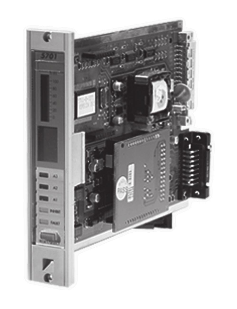
21 CHAPTER 2 - SYSTEM DESCRIPTION 4. SINGLE CHANNEL CONTROL CARDS 4.1 General 5701 % LEL The 5701 Single Channel Control Card provides control, display and alarm facilities for a connected gas detector. The front panel display indicates the gas reading and channel status while LEDs are used for alarms. A push-button is provided for resetting the alarms and selecting the card for use with the Engineering Card. The operation of the control card is microprocessor controlled and is fully definable for a wide range of connected gas detectors and application requirements. The software configuration setup is stored in an EEPROM. There are two types of control card depending on the type of gas detector being fitted to the system: A3 A2 A1 INHIBIT FAULT RESET/SELECT a. Single Channel Control Card 4-20mA. Part Number A b. Single Channel Control Card Catalytic. Part Number A Each of the above control cards consist of a single channel control card fitted with the respective plug-in sensor drive module. An optional Analogue Output Module can also be plugged into the single channel control card to provide a remote output of the channel card readings. 2-8
22 CHAPTER 2 - SYSTEM DESCRIPTION 4.2 Single Channel Control Card The Single Channel Control Card carries out the control functions for a single loop of gas detection as follows: a. Processes the incoming sensor drive module signal. b. Displays the signal level on the front panel liquid crystal display. c. Compares the signal level with pre-defined alarm limits. d. When the pre-defined alarm limits are exceeded, raises the alarms by lighting up front panel LEDs and operating optional connected relays. e. Informs other cards with the alarm status information. f. Self validates the operation of its circuit components, software operation and the condition of the sensor. 4.3 Sensor Drive Modules Two sensor drive modules are provided: a. Sensor Drive Module, 4-20mA, Part Number A-0283 b. Sensor Drive Module Catalytic, Part Number A-0284 The Sensor Drive Module conditions the incoming catalytic or 4-20mA sensor signal and provides the necessary sensor power supply. It contains all the circuitry necessary to generate the voltages and currents required to drive the sensor, the circuitry to acquire the sensor signal and to scale the sensor signal to a standard output. The sensor drive modules are factory fitted and plug directly onto the channel control card. 4.4 Analogue Output Module An optional Analogue Output Module, (Part Number A-0285), may be factory fitted to the Single Channel Control Card and is used on a channel of gas detection to provide an isolated current loop output which follows the sensor signal level. This may be set electronically to produce a 0-20mA output or a 4-20mA output and can be used to operate a chart recorder, etc. 2-9
23 CHAPTER 2 - SYSTEM DESCRIPTION 4.5 Single Channel Control Card Physical Layout The physical layout of the Single Channel Control Card is shown below. The Sensor Drive Modules plug into the 14-way connectors J1 and J2 while the Analogue Output Module, when fitted, plugs into J3 and J4. Link LK1, available on MkII cards only, is used when individually powering control cards See Chapter 4, Section Way Socket (SK2) To Backplane Fuse FS1 15-Way D Type Socket (SK1) To Interface or Relay Link LK1 Cards (MkII Cards Only) Way Connectors To Sensor Drive Modules 8-Way Analogue Output Module Connectors Liquid Crystal Display LEDs Reset/Select Push Button Switch 2-10
24 CHAPTER 2 - SYSTEM DESCRIPTION 5. FIELD INTERFACE AND RELAY CARDS 5.1 General The Field Interface Card and the four types of relay card provide the interface between a Single Channel Control Card and the field wiring. 5.2 Field Interface Card (Part Number A-0326) General For use in systems with master relays. Used on all channels except the master. Provides connections between the sensor and the control card only. No relays fitted. 2-11
25 CHAPTER 2 - SYSTEM DESCRIPTION Rear Access Connections Slot Location Ground 25 Sensor S Connection 27 Sensor NS Connection 29 Analogue O/P (+) 31 Remote Inhibit In V (Out/In) Ground 28 Sensor 01 Connection 30 Not Connected 32 Analogue O/P (-) 34 Remote Reset In 36 0V (Out/In) User Terminal Reference 2-12
26 CHAPTER 2 - SYSTEM DESCRIPTION Front Access Connections User Terminal Reference 0V (Out/In) 36 Remote Reset In 34 Analogue O/P (-) 32 Not Connected 30 Sensor 01 Connection 28 Ground V (Out/In) 33 Remote Inhibit In 31 Analogue O/P (+) 29 Sensor NS Connection 27 Sensor S Connection 25 Ground Slot Location 2-13
27 CHAPTER 2 - SYSTEM DESCRIPTION 5.3 Double SPCO Relay Card (Part Number A-0327) General Provides connections between the sensor and the control card in the same way as the Field Interface Card. In addition, single pole relays provide voltage free contact outputs for the A1 alarm level, A2 alarm level and fault condition Rear Access Connections Slot Location Fault NC 1 Fault COM 3 Not Connected 5 A1(1) NC 7 A1(1) COM 9 A2(1) NC 11 2 Fault NO 4 Not Connected 6 Not Connected 8 A1(1) NO 10 A2(1) COM 12 A2(1) NO Ground 25 Sensor S Connection 27 Sensor NS Connection 29 Analogue O/P (+) 31 Remote Inhibit In V (Out/In) Ground 28 Sensor 01 Connection 30 Not Connected 32 Analogue O/P (-) 34 Remote Reset In 36 0V (Out/In) User Terminal Reference NC = Normally Closed. NO = Normally Open. COM = Common. Relay contact conditions refer to the no power state of the relay. 2-14
28 CHAPTER 2 - SYSTEM DESCRIPTION Front Access Connections User Terminal Reference 0V (Out/In) 36 Remote Reset In 34 Analogue O/P (-) 32 Not Connected 30 Sensor 01 Connection 28 Ground V (Out/In) 33 Remote Inhibit In 31 Analogue O/P (+) 29 Sensor NS Connection 27 Sensor S Connection 25 Ground A2(1) NO 12 A2(1) COM 10 A1(1) NO 8 Not Connected 6 Not Connected 4 Fault NO 2 11 A2(1) NC 9 A1(1) COM 7 A1(1) NC 5 Not Connected 3 Fault COM 1 Fault NC Slot Location NC = Normally Closed. NO = Normally Open. COM = Common. Relay contact conditions refer to the no power state of the relay. 2-15
29 CHAPTER 2 - SYSTEM DESCRIPTION 5.4 Triple SPCO Relay Card (Part Number A-0328) General Provides connections between the sensor and the control card in the same way as the Field Interface Card. In addition, single pole relays provide voltage free contact outputs for the A1 alarm level, A2 alarm level, A3 alarm level, fault and inhibit conditions Rear Access Connections Slot Location Fault NC 1 Fault COM 3 Inhibit NC 5 A1(1) NC 7 A1(1) COM 9 A2(1) NC 11 A3(1) NC 13 A3(1) COM 15 Not Connected 17 Not Connected 19 Not Connected 21 Not Connected 23 Ground 25 Sensor S Connection 27 Sensor NS Connection 29 Analogue O/P (+) 31 Remote Inhibit IN V (Out/In) 35 2 Fault NO 4 Inhibit COM 6 Inhibit NO 8 A1(1) NO 10 A2(1) COM 12 A2(1) NO 14 A3(1) NO 16 Not Connected 18 Not Connected 20 Not Connected 22 Not Connected 24 Not Connected 26 Ground 28 Sensor 01 Connection 30 Not Connected 32 Analogue O/P (-) 34 Remote Reset In 36 0V (Out/In) User Terminal Reference NC = Normally Closed. NO = Normally Open. COM = Common. Relay contact conditions refer to the no power state of the relay. 2-16
30 CHAPTER 2 - SYSTEM DESCRIPTION Front Access Connections User Terminal Reference 0V (Out/In) 36 Remote Reset In 34 Analogue O/P (-) 32 Not Connected 30 Sensor 01 Connection 28 Ground 26 Not Connected 24 Not Connected 22 Not Connected 20 Not Connected 18 Not Connected 16 A3(1) NO 14 A2(1) NO 12 A2(1) COM 10 A1(1) NO 8 Inhibit NO 6 Inhibit COM 4 Fault NO V (Out/In) 33 Remote Inhibit In 31 Analogue O/P (+) 29 Sensor NS Connection 27 Sensor S Connection 25 Ground 23 Not Connected 21 Not Connected 19 Not Connected 17 Not Connected 15 A3(1) COM 13 A3(1) NC 11 A2(1) NC 9 A1(1) COM 7 A1(1) NC 5 Inhibit NC 3 Fault COM 1 Fault NC Slot Location NC = Normally Closed. NO = Normally Open. COM = Common. Relay contact conditions refer to the no power state of the relay. 2-17
31 CHAPTER 2 - SYSTEM DESCRIPTION 5.5 Triple DPCO Relay Card (Part Number A-0329) General Provides connections between the sensor and the control card in the same way as the Field Interface Card. In addition, single pole relays provide voltage free contact outputs for 2 x A1 alarm level, 2 x A2 alarm level, 2 x A3 alarm level, fault and inhibit conditions Rear Access Connections Slot Location Fault NC 1 Fault COM 3 Inhibit NC 5 A1(1) NC 7 A1(1) COM 9 A2(1) NC 11 A3(1) NC 13 A3(1) COM 15 A1(2) NC 17 A2(2) NC 19 A2(2) COM 21 A3(2) NC 23 Ground 25 Sensor S Connection 27 Sensor NS Connection 29 Analogue O/P (+) 31 Remote Inhibit In V (Out/In) 35 2 Fault NO 4 Inhibit COM 6 Inhibit NO 8 A1(1) NO 10 A2(1) COM 12 A2(1) NO 14 A3(1) NO 16 A1(2) COM 18 A1(2) NO 20 A2(2) NO 22 A3(2) COM 24 A3(2) NO 26 Ground 28 Sensor 01 Connection 30 Not Connected 32 Analogue O/P (-) 34 Remote Reset In 36 0V (Out/In) User Terminal Reference NC = Normally Closed. NO = Normally Open. COM = Common. Relay contact conditions refer to the no power state of the relay. 2-18
32 CHAPTER 2 - SYSTEM DESCRIPTION Front Access Connections User Terminal Reference 0V (Out/In) 36 Remote Reset In 34 Analogue O/P (-) 32 Not Connected 30 Sensor 01 Connection 28 Ground 26 A3(2) NO 24 A3(2) COM 22 A2(2) NO 20 A1(2) NO 18 A1(2) COM 16 A3(1) NO 14 A2(1) NO 12 A2(1) COM 10 A1(1) NO 8 Inhibit NO 6 Inhibit COM 4 Fault NO V (Out/In) 33 Remote Inhibit In 31 Analogue O/P (+) 29 Sensor NS Connection 27 Sensor S Connection 25 Ground 23 A3(2) NC 21 A2(2) COM 19 A2(2) NC 17 A1(2) NC 15 A3(1) COM 13 A3(1) NC 11 A2(1) NC 9 A1(1) COM 7 A1(1) NC 5 Inhibit NC 3 Fault COM 1 Fault NC Slot Location NC = Normally Closed. NO = Normally Open. COM = Common. Relay contact conditions refer to the no power state of the relay. 2-19
33 CHAPTER 2 - SYSTEM DESCRIPTION 5.6 High Integrity Relay Card (Part Number A-0330) General Provides connections between the sensor and the control card in the same way as the Field Interface Card. This card is used to provide master alarm functions or a mixture of master and individual alarms. The card is fitted with eight relays, seven of which are fully configurable while the eighth is used for fault alarm. The relay states are monitored by the control card to ensure correct operation of the relays. In the case of a malfunction, the fault relay of the high integrity relay card deenergises. The fault relay shall always be monitored in order to ensure correct operation of the system. Additional capabilities are available with this card including delayed switch on or switch off of the alarm relays. Note: The High Integrity Relay Card can only be used with MKII Control Cards. 2-20
34 CHAPTER 2 - SYSTEM DESCRIPTION Rear Access Connections IMPORTANT Refer to configuration printout, or use the Relays Screen of the Engineering Interface Software, to determine the relay function. Slot Location RL1-NC (Fault) 1 RL1-COM (Fault) 3 RL2 NC 5 RL3 NC 7 RL3 COM 9 RL4 NC 11 RL5 NC 13 RL5 COM 15 RL6 NC 17 RL7 NC 19 RL7 COM 21 RL8 NC 23 Ground 25 Sensor S Connection 27 Sensor NS Connection 29 Analogue O/P (+) 31 Remote Inhibit In V (Out/In) 35 2 RL1 NO (Fault) 4 RL2 COM 6 RL2 NO 8 RL3 NO 10 RL4 COM 12 RL4 NO 14 RL5 NO 16 RL6 COM 18 RL6 NO 20 RL7 NO 22 RL8 COM 24 RL8 NO 26 Ground 28 Sensor 01 Connection 30 Not Connected 32 Analogue O/P (-) 34 Remote Reset In 36 0V (Out/In) User Terminal Reference NC = Normally Closed. NO = Normally Open. COM = Common. Relay contact conditions refer to the no power state of the relay. 2-21
35 CHAPTER 2 - SYSTEM DESCRIPTION Front Access Connections IMPORTANT Refer to configuration printout, or use the Relays Screen of the Engineering Interface Software, to determine the relay function. User Terminal Reference 0V (Out/In) 36 Remote Reset In 34 Analogue O/P (-) 32 Not Connected 30 Sensor 01 Connection 28 Ground 26 RL8 NO 24 RL8 COM 22 RL7 NO 20 RL6 NO 18 RL6 COM 16 RL5 NO 14 RL4 NO 12 RL4 COM 10 RL3 NO 8 RL2 NO 6 RL2 COM 4 RL1 NO (Fault) V (Out/In) 33 Remote Inhibit In 31 Analogue O/P (+) 29 Sensor NS Connection 27 Sensor S Connection 25 Ground 23 RL8 NC 21 RL7 COM 19 RL7 NC 17 RL6 NC 15 RL5 COM 13 RL5 NC 11 RL4 NC 9 RL3 COM 7 RL3 NC 5 RL2 NC 3 RL1 COM (Fault) 1 RL1 NC (Fault) Slot Location NC = Normally Closed. NO = Normally Open. COM = Common. Relay contact conditions refer to the no power state of the relay. 2-22
36 CHAPTER 2 - SYSTEM DESCRIPTION 6. ENGINEERING CARD The Engineering Card (Part Number A-0361) is used on a System 57 rack to provide a common interface that enables the user to perform all the required functions to commission and operate each fitted control card. The front panel is fitted with a series of tactile pushbuttons for the operation of various functions, LEDs to provide rack power and communications status and a mini DIN socket for the connection of a serial printer, computer or an engineering key. The Engineering Key is used to unlock functions that can alter the operation of a control card. PRINT The Engineering Card is always fitted into the righthand slot of the rack and provides: a. Routeing of the 24V dc input from the DC Input Card to the backplane of the rack. BEAD ma ZERO SPAN INHIBIT ALARMS SIGNAL 1 ST SPAN CLOCK b. A backplane serial communications controller and monitor. c. A time and date reference. d. An RS232 external engineering interface. e. Depending upon the security level, the operation of the following rack facilities: Catalytic sensor head current monitoring and adjustment. Alarm set point checking, adjustment and testing. Sensor signal zero adjustment. Sensor signal span adjustment and setting of sensor life monitoring values. Sensor line monitoring. Enabling of control card alarm inhibit. Checking and adjustment of the system clock. f. Self validation of the operation of its circuit components, software operation and the backplane communications. 2-23
37 CHAPTER 2 - SYSTEM DESCRIPTION One of four optional modules may be fitted to the Engineering Card: a. Master Alarm Update Module This facility provides an indication when a new alarm occurs on any channel in the rack, even if a previous alarm condition already exists. b. Event Printing Module This facility provides time stamped reporting of alarm and fault events as they occur and system status at predetermined regular intervals. c. Modbus Interface Module RS422/485 This facility provides for digital communication between the System 57 Control System and an external computer system using the RS422/485 serial data format and the Modbus communication protocol. d. Modbus Interface Module RS232 This facility provides for digital communication between the System 57 Control System and an external computer system using the RS232 serial data format and the Modbus communication protocol. 2-24
38 CHAPTER 2 - SYSTEM DESCRIPTION 7. DC INPUT CARD 7.1 General The dc power to the rack normally enters the sub-rack via the DC Input Card (Part Number A-0325). This power may be supplied by the user from an external nominal 24V dc supply. The dc supply is routed through the Engineering Card and sub-rack back plane to all cards in the rack and is protected by a fuse on the DC Input Card. There is a two part terminal block, TB1, to aid removal of the card without disconnecting each of the connected wires. If required, a stand-by backup battery supply may also be connected to the auxiliary dc input connections. The PSU and AUX connections are isolated from each other by diodes. The DC Input Card also provides RFI filtering and reverse polarity protection. 2-25
39 CHAPTER 2 - SYSTEM DESCRIPTION 7.2 Rear Access Connections User Terminal Reference TB V In (PSU 1) 11 0V In (PSU 1) V In (PSU 2*) or +24V Out (PSU 1) 9 0V In (PSU 2) or 0V Out (PSU 1) 8 +24V In (AUX 1) 7 0V In (AUX 1) 6 +24V In (AUX 2*) or +24V Out (AUX 1) 5 0V In (AUX 2) or 0V Out (AUX 1) 4 +24V Out (Fused) 3 0V Out (Fused) 2 Ground 1 Ground TB Connections to the Engineering Card optional modules. Functions vary depending upon type of module fitted. Slot Location * PSU 1 and PSU 2 (and AUX 1 and AUX 2) must be compatible with parallel connection. Note: For high integrity systems it is possible to connect the dc power direct to individual relay cards. 2-26
40 CHAPTER 2 - SYSTEM DESCRIPTION 7.3 Front Access Connections Slot Location TB TB1 1 Ground 2 Ground 3 0V Out (Fused) 4 +24V Out (Fused) 5 0V In (AUX 2) or 0V Out (AUX 1) 6 +24V In (AUX 2*) or +24V Out (AUX 1) 7 0V In (AUX 1) 8 +24V In (AUX 1) 9 0V In (PSU 2) or 0V Out (PSU 1) V In (PSU 2*) or +24V Out (PSU 1) 11 0V In (PSU 1) Connections to the Engineering Card optional modules. Functions vary depending upon type of module fitted V In (PSU 1) User Terminal Reference * PSU 1 and PSU 2 (and AUX 1 and AUX 2) must be compatible with parallel connection. Note: For high integrity systems it is possible to connect the dc power direct to individual relay cards. 2-27
41 CHAPTER 2 - SYSTEM DESCRIPTION 8. AC TO DC POWER SUPPLY UNITS 8.1 Types of Power Supply Unit There are two types of AC to DC power supply units: a. 8-Way AC to DC Power Supply Unit (Part Number A-0406) A 1U high half width 19 inch rack mounted unit that contains a single 50W Switched Mode AC to DC Power Supply Module. b. 16-Way AC to DC Power Supply Unit (Part Number A- 0405) A 1U high 19 inch rack mounted unit that contains a single 50W Switched Mode AC to DC Power Supply Module. Both power supply units will operate from an 85V to 264V, 47Hz to 440Hz ac supply, or a 110V to 340V dc supply (Refer to Honeywell Analytics for information on dc supplies). 8.2 Power Supply Unit Upgrades Both power supply units are provided with internal connections to enable a power upgrade to 100W by the addition of a second 50W Switched Mode AC to DC Power Supply Module (Part Number A-0440). A second sub-unit (Part Number A-0441) can be fitted to the basic 16-way power supply unit if more than 100W is required to operate the system. The additional sub-unit will contain a 50W Switched Mode AC to DC Power Supply Module as standard and will therefore give an additional 50W of available power. If required a further 50W Switched Mode AC to DC Power Supply Module (Part Number A-0440) can be added to this second sub-unit to bring the power availability up to 200W. The switched mode power supply modules used are fully overload protected and are designed to be connected together. 8.3 Power Supply Connections The input ac power supply is connected via a three core cable at the rear of each unit. The nominal 24V dc output supply is connected via a twin core cable at the rear of each unit. 2-28
42 CHAPTER 2 - SYSTEM DESCRIPTION Way AC to DC Power Supply Unit Layout Front View Top View Rear View Input ac Supply Voltage 24V dc Output Voltage. 50W per Fitted Module Way AC to DC Power Supply Unit Layout Optional Sub Unit Input ac Supply Voltage 24V dc Output Voltage. 50W per Fitted Module Input ac Supply Voltage 24V dc Output Voltage. 50W per Fitted Module 2-29
43 CHAPTER 2 - SYSTEM DESCRIPTION W Sub-Unit Layout The 50W Sub-unit is fitted with a single 50W Switched Mode AC to DC Power Supply Module as shown below: Top View 50W Switched Mode AC to DC Power Supply Module This type of unit is identified on the identification label as follows: POWER SUPPLY UNIT A-0405 Iss. 2 INPUT = V AC OUTPUT = 24V DC Hz POWER = 50W OR V DC = 100W Indicates 50W Unit W Sub-Unit Layout The 100W Sub-unit is a 50W Sub-unit with an additional 50W Switched Mode AC to DC Power Supply Module fitted as shown below: Top View 50W Switched Mode AC to DC Power Supply Module Additional 50W Switched Mode AC to DC Power Supply Module This type of unit is identified on the identification label as follows: POWER SUPPLY UNIT A-0405 Iss. 2 INPUT = V AC OUTPUT = 24V DC Hz POWER = 50W OR V DC = 100W Indicates 100W Unit 2-30
44 CHAPTER 2 - SYSTEM DESCRIPTION 9. FRONT PANEL BLANKING PANEL Matching blank front panels are available for fitting to the rack in all unused single channel control card spaces. 2-31
45 CHAPTER 2 - SYSTEM DESCRIPTION 2-32
46 CHAPTER 3 CONTROLS AND FACILITIES 5701 SERIES CONTROL SYSTEM CHAPTER 3 CONTROLS AND FACILITIES 3-1
47 CHAPTER 3 CONTROLS AND FACILITIES CONTENTS Section Page 1. INTRODUCTION SINGLE CHANNEL CONTROL CARD General Liquid Crystal Display LEDs Reset/Select Push-button Extraction Slot Display Label and Cover ENGINEERING CARD General LED Indicators Engineering Push-buttons
48 CHAPTER 3 CONTROLS AND FACILITIES 1. INTRODUCTION The 5701 Series Control System is equipped to provide the operational and engineering facilities necessary to fully maintain a system of gas detection equipment. Each control card within a rack system displays a sensor reading, alarm status and condition of that channel. Further information can be gathered and, depending on the security status, certain settings can be adjusted by means of an Engineering Card fitted to the rack. The relay outputs of the system are configured to provide a range of output alarm functions as follows: a. Fault Alarm The fault alarm activates when a fault is detected in the control card or associated sensor and is not user configurable. In addition the FAULT LED will be illuminated. b. Inhibit Alarm The inhibit alarm activates when the system alarms are inhibited for any reason and is not user configurable. In addition the INHIBIT LED will be illuminated. c. A1, A2 and A3 Level Alarms The A1, A2 and A3 level alarms are activated when the level of gas being measured crosses the preconfigured alarm threshold. In addition the relevant LED will be illuminated. d. STEL Alarm (Short Term Exposure Limit) The STEL alarm will be activated when the time weighted average concentration of a toxic gas, usually averaged over 10, 15 or 30 minutes, crosses a preconfigured threshold. When active STEL will be shown on the message display of the control card. For certain relay cards and configurations, the alarm LED associated during setup to the STEL alarm will be illuminated. 3-3
49 CHAPTER 3 CONTROLS AND FACILITIES e. LTEL Alarm (Long Term Exposure Limit). The LTEL alarm will be activated when the time weighted average concentration of a toxic gas, usually averaged over 8 hours, crosses a preconfigured threshold. When active LTEL will be shown on the message display of the control card. For certain relay cards and configurations, the alarm LED associated during setup to the LTEL alarm will be illuminated. f. Rate Alarm (Version 2Vx Software only) The rate alarm predicts the future gas concentration by monitoring the rate of rise of the sensor signal and provides an early alarm indication before the sensor signal reaches the next level alarm set point. g. Individual Alarm An individual alarm is caused by the input to an individual control channel crossing a preconfigured threshold and is not related to any other control channel. The relevant LED (A1, A2, A3, Fault, Inhibit) will illuminate on the control card with the alarm condition. CAUTION* Depending upon the configuration, control cards configured for Zoned, Master or Voted alarms may not give individual alarm outputs. h. Zoned Alarm* A zoned alarm is caused by the input to any control channel, from a sensor in a designated area, crossing a preconfigured threshold. The relevant LED (A1, A2, A3, Fault, Inhibit) will illuminate on the control card with the alarm condition and also on the control card designated the Zone Master Card (unless it is fitted with a High Integrity Relay Card). i. Master Alarm* A master alarm is caused by the input to any designated control channel within a single rack crossing a preconfigured threshold. The relevant LED (A1, A2, A3, Fault, Inhibit) will illuminate on the control card with the alarm condition and also on the control card designated the Master Card (unless it is fitted with a High Integrity Relay Card). 3-4
50 CHAPTER 3 CONTROLS AND FACILITIES j. Voted Alarm* A voted alarm is caused by the simultaneous presence of an identical alarm on more than one control channel within a preconfigured group. The relevant LED (A1, A2, A3, Fault, Inhibit) will illuminate on the control cards with the alarm condition and also on the control card designated the Vote Master Card (unless it is fitted with a High Integrity Relay). Vote compensation (Version 2V6 and above Software only) may be applied to the voted alarm output operation by selecting one of the following configurations: a. No compensation. b. Faults counted as alarms. c. Faults and inhibits counted as alarms. d. Vote count reduction on faults. e. Vote count reduction on faults and inhibit. Vote compensation is useful to ensure that sensors in fault (or inhibit) do not prevent voted alarm outputs. k. Update Alarm (Version 2Vx Software only) The update alarm facility provides a common alarm indication whenever a new alarm occurs, even if a previous alarm condition exists. The update alarm can be configured to operate on a single channel or on a grouped alarm. eg. master or zoned. The update alarm is especially useful in systems configured with only master or group/zone relays, where the occurrence of subsequent alarms will not cause further relay output compared to that caused by the initial alarm. The relevant LED (A1, A2, A3, Fault, Inhibit) will illuminate on the control card with the alarm condition as described in section 2.3. When relays are used for signalling update alarms, no other alarms or messages must be allocated to them. Configuration of update messages for inhibit should be avoided. l. Rising Alarm A rising alarm is caused by a rising level of the parameter being measured crossing a preconfigured threshold and will also cause the associated alarm LED to illuminate. 3-5
51 CHAPTER 3 CONTROLS AND FACILITIES m. Falling Alarm A falling alarm is caused by a falling level of the parameter being measured crossing a preconfigured threshold and will also cause the associated alarm LED to illuminate. n. Latched Alarm A latched alarm is an alarm that will remain active even though the level monitored no longer crosses the alarm threshold. The alarm LED will remain lit until the alarm reset is operated. o. Non-latched Alarm A non-latched alarm is an alarm that only remains active while the level being monitored crosses the alarm threshold. The alarm LED will remain lit while the alarm level remains but will automatically be reset when the level monitored no longer crosses the alarm threshold. p. Normally Energised A normally energised relay is activated when the power is removed from it, (eg. in the event of a system power failure). The LEDs will illuminate when an alarm or fault condition occurs irrespective of the relay configured state. q. Normally De-energised A normally de-energised relay is activated when the power is applied to it, (eg. in the event of an alarm condition). The LEDs will illuminate when an alarm or fault condition occurs irrespective of the relay configured state. r. Time Delay Alarms (Version 2Vx Software only) The operation in response to alarm events of certain relays may be modified by applying a delay function to the relays. Time delay functions are available to delay the activation of a relay for a short period after an alarm event occurs and/or to maintain relay activation for a period after the alarm event has cleared. The time delay facilities are available for relays RL2 to RL8 of the High Integrity Relay Card only. The time delay function is useful to prevent spurious alarms and to ensure appropriate minimum operating times for external electrical apparatus connected to the relay. 3-6
52 CHAPTER 3 CONTROLS AND FACILITIES Control Card Versions Since the original launch of System 57 several new features have been added to enhance the capabilities of the 5701 Control Card. The key features for each software version are illustrated in the following table. Note that the software fitted to existing cards cannot be upgraded, however all versions of software and hardware are fully backward compatible so new cards can be incorporated into existing systems without difficulty. Control Card and Software Versions Function Mark I Mark II 0v7 1v1 2V4 2V5 2V6 Fault Alarm Yes Yes Yes Yes Yes Inhibit Alarm Yes Yes Yes Yes Yes A1, A2, A3 Alarm Yes Yes Yes Yes Yes STEL/LTEL Alarm No Yes Yes Yes Yes 30 Minute STEL No No Yes Yes Yes Rate Alarm No No Yes Yes Yes Zoned Alarm Yes Yes Yes Yes Yes Master Alarm Yes Yes Yes Yes Yes Voted Alarm Yes Yes Yes Yes Yes Vote Compensation No No No No Yes Update Alarm No No Yes* Yes* Yes* Time Delay Relays No No Yes Yes Yes Standard Relay Cards Yes Yes Yes Yes Yes High Integrity Relay Cards No No Yes* Yes* Yes Fault Warm-Up No No Yes Yes Yes MODBUS Compatible No Yes** Yes Yes Yes Complex Alarms include 5704 No No Yes Yes Yes *Special configuration criteria apply, consult Honeywell Analytics or your local distributor for more details. **Restricted functionality only, consult Honeywell Analytics or your local distributor for more details. 3-7
53 CHAPTER 3 CONTROLS AND FACILITIES 2. SINGLE CHANNEL CONTROL CARD 2.1 General The Single Channel Control Card provides the necessary power supplies to the associated sensor and conditions the incoming sensor signal. The received sensor signal is then processed by the microprocessor and the resultant value and any necessary alarm action, depending on the channel configuration, is carried out. The channel card front panel can be subdivided into five areas: 5701 % LEL Display Label and Cover. LCD Display. Alarm LEDs. Reset/Select Push-button. Extraction Slot. A3 A2 A1 INHIBIT FAULT RESET/SELECT 3-8
54 CHAPTER 3 CONTROLS AND FACILITIES 2.2 Liquid Crystal Display General The LCD provides a display of the connected sensor reading and its status, or if maintenance is being carried out on the sensor, information on the sensor set points and calibration data The display can be divided into four parts: Analogue Display. Message Display % LEL Digital Display. Icon Display Analogue Display This consists of 25 segments providing an indication of the sensor gas reading in the form of an analogue bar graph which covers the sensor range between -10% and +110% fsd. There are two possible modes of operation: a. Solid in which the segments fill the area between zero and the actual gas reading. b. Single Line in which a single segment indicates the actual gas reading. Each of these modes can be operated as either a rising or falling display. A peak reading facility is available which maintains a segment at the highest, or lowest, gas value obtained by the sensor since the previous peak reading reset. This is a useful recording tool for the behaviour of the connected sensor. The default mode of operation is solid current gas reading display with a peak reading facility. % LEL % LEL % LEL % LEL
55 CHAPTER 3 CONTROLS AND FACILITIES Digital Display The digital display is a four character, seven segment display which provides either an indication of the sensor gas reading or a value relating to a function selected from the Engineering Card. Depending on the sensor range and the configuration setting, the digital display shows a gas value to either no decimal place (the default setting) or to one decimal place Message Display The message display consists of a four character, 14 segment display which provides intelligent reporting of the sensor status or information on a selected engineering function. For control cards fitted with the high integrity relay outputs performing master, zone or voted alarms, the alarm state will also be indicated as follows: BEAM - Beam Blocked Alarm MSTR - Master Alarm ZONE - Zoned Alarm VOTE - Voted Alarm In the case of an Update alarm the cause of the update is indicated as follows: -FT- - Fault Alarm -IN- - Inhibit Alarm -A1- - A1 alarm -A3- - A2 alarm -A3- - A3 alarm -ST- - STEL alarm -LT- - LTEL alarm -RT- - Rate alarm Icon The icon provides a simple indication that the display is functioning and changes when the channel card is selected for operation with the Engineering Card. Normal Operation Selected 3-10
56 CHAPTER 3 CONTROLS AND FACILITIES 2.3 LEDS Five LEDs on the front panel of the control card indicate the operational status of the channel as follows: a. FAULT - Amber LED The fault LED provides an indication in the event of a sensor hardware failure, if the sensor signal is outside pre-defined limits or if the channel card has detected a hardware or software fault. b. INHIBIT - Amber LED The inhibit LED indicates when the channel is in the inhibit condition. This condition can be selected manually and remotely, or occurs automatically: during start-up for a pre-defined period of approximately 30 seconds, when carrying out certain engineering functions such as zero, span, 1st span and alarm test. Depending upon the configuration, the control card may enter the inhibit mode for a short period of time immediately after a fault condition is cleared During the inhibit condition, the channel card will continue to read the gas sensor reading, however, no action is taken in the event of an alarm condition being exceeded. c. A1 - Red LED The A1 LED indicates that the preset first level gas alarm has been exceeded. This alarm will not function in the event of either a fault or inhibit condition being active. d. A2 - Red LED The A2 LED indicates that the preset second level gas alarm has been exceeded. This alarm will not function in the event of either a fault or inhibit condition being active. e. A3 - Red LED The A3 LED indicates that the preset third level gas alarm has been exceeded. This alarm will not function in the event of either a fault or inhibit condition being active. 3-11
57 CHAPTER 3 CONTROLS AND FACILITIES 2.4 Reset/Select Push-button The front panel RESET/SELECT push-button provides four functions depending upon how it is operated: a. Alarm Reset The RESET/SELECT push-button, when pressed momentarily, resets any latched alarm, non active alarms, faults, warning or information messages, clears the display peak reading indicator and will acknowledge an update if such a condition is present. Note: 'Non active alarms' describe the occasion where the alarm condition has cleared but the alarm is still indicated due to latched information. For non-latched setups the indicated alarms will clear automatically when the alarm condition clears. b. Channel Select The RESET/SELECT push-button, when pressed for approximately 1.5 seconds, selects the control card for operations controlled from the Engineering Card. c. Extended Reset The RESET/SELECT push-button, when pressed continuously for five seconds: i. Clears the channel maximum and minimum gas readings. ii. Resets any active short term (STEL) and long term (LTEL) exposure alarms clearing the timer to zero. iii. For active time delay functions, activates any relay with impending trigger and clears any relay being held. d. Channel Deselect The RESET/SELECT push-button, when pressed momentarily while a control card is selected, deselects the control card from the Engineering Card functions. Note: The control card may also be deselected by pressing the key. 3-12
58 CHAPTER 3 CONTROLS AND FACILITIES 2.5 Extraction Slot An extraction tool is used in conjunction with the extraction slot, just below the select push-button, to remove the card from the rack. The extraction tool is provided as part of the Key Kit (05701-A-0550) supplied with each rack assembly. The card is removed by first unscrewing the two card securing screws, one at the top of the card and the other at the bottom of the card, and then hooking the extraction tool into the extraction slot and then gently pulling the card out of the rack. 2.6 Display Label and Cover A clear perspex cover clips to the front panel and retains the label which provides identification of the control card type, sensor scale, LED and push-button functions. Two different label colours are used: a. Grey/Blue - Control cards fitted with Catalytic Sensor Drive Modules. b. Violet - Control cards fitted with 4-20mA Sensor Drive Modules. The perspex cover is removed by first removing the control card from the rack and then locating a small hole on the inside of the front panel just above the LCD display. A blunt object, such as a screwdriver, is then pushed through the hole to unclip the perspex cover. A small recess in the perspex cover allows a label to be inserted to indicate the channel tag name or gas type. Extraction Hole 3-13
Operating Instructions
 Operating Instructions System 57 Module Kit (05701-A-0309) Alarm Update Panel (05701-A-0339) Helping to make a safer world Ensure that you read and understand these instructions BEFORE operating the equipment.
Pioneer-R16 Gas Monitor Operator s Manual
 Pioneer-R16 Gas Monitor Operator s Manual Edition 7/2/97 RKI INSTRUMENTS, INC RKI Instruments, Inc. 33248 Central Ave, Union City, CA 94587 (510) 441-5656 Chapter 1: Description About the Pioneer-R16 Gas
System 57. An advanced World of intelligent gas detection system management
 An advanced World of intelligent gas detection system management A World of control technology High precision, intelligent control Master / voted alarm options High packing density Flexible I/O configuration
SCAN200E USER S MANUAL
 SCAN200E USER S MANUAL Code No. 2071 1052 rev. 1.4 Code No. 2071 1052 Rev. 1.4 Page 2/16 SCAN200E User s Manual Foreword This manual is for SCAN200E Controller running software version 2.03 or later. We
Installation, Operating and Maintenance Manual
 STATUS ZONES CONTROLS FIRE FAULT DISABLED FIRE 1 2 3 4 5 6 7 8 TEST FAULT DISABLED 1 5 BUZZER SILENCE RESET 1 2 TEST 2 6 LAMP TEST 3 SUPPLY 3 7 SYSTEM FAULT 4 8 SOUNDERS ACTIVATE/ SILENCE 4 FAULTS INSTRUCTIONS
System 57. An advanced world of intelligent gas detection system management
 An advanced world of intelligent gas detection system management A world of control technology High precision, intelligent control Master/voted alarm options High packing density Flexible I/O configuration
REGARD. REGARD 4-20 AND Ex CHANNEL CARDS INSTALLATION AND OPERATING MANUAL (FOR ATEX VERSION CARDS)
") REGARD REGARD 4-20 AND Ex CHANNEL CARDS INSTALLATION AND OPERATING MANUAL (FOR ATEX VERSION CARDS) Part No. 4206712 For use with Regard 4-20 and Ex cards software version 3.0 or later. Draeger Safety UK
REGARD REGARD 4-20 AND Ex CHANNEL CARDS INSTALLATION AND OPERATING MANUAL (FOR ATEX VERSION CARDS) Part No. 4206712 For use with Regard 4-20 and Ex cards software version 3.0 or later. Draeger Safety UK
APPLICATION DATA SHEET
 APPLICATION DATA SHEET Control Systems Transmitters Sensors Accessories Wall, 19 Rack or Panel Mounting Units 110/230V 50/60Hz AC operation 250 Addressable devices as: Relays, 4-20 Inputs or Gas Detectors
PNC 1000 SERIES 2, 4, 8 Zone Fire Alarm Control Panel
 PNC 1000 SERIES 2, 4, 8 Zone Fire Alarm Control Panel INSTALLATION, OPERATION AND MAINTENANCE MANUAL Version: CN-PM-1000.VER1.1-12/2012 EN54 INFORMATION In accordance with EN 54-2 clause 13.7, the maximum
Operating Instructions
 Operating Instructions Sensepoint / Signalpoint Bridge to 4 20mA Converter TOTAL ENVIRONMENTAL SOLUTIONS Ensure that you read and understand these instructions BEFORE operating the equipment. Please pay
Fire Extinguishing Control Panel INSTRUCTION MANUAL. Revision 8/ Instruction Manual Page 1 Revision 8/01.17 of 63
 Fire Extinguishing Control Panel FS5200Е INSTRUCTION MANUAL Revision 8/01.17 Instruction Manual Page 1 1. 2. 3. 4. 4.1. 4.2. 4.2.1. 4.2.2. 4.2.3. 4.2.4. 4.2.5. 4.2.6. 4.2.7. 4.2.8. 4.2.9. 4.2.10. 4.2.11.
P R O D U C T D ATA S H E E T
 P R O D U C T D ATA S H E E T www.internationalgasdetectors.com Transmitters Control Systems Sensors Accessories TOCSIN 90 SYSTEM UPGRADE Use existing MK3 Pellistor Flammable Gas Sensors and upgrade to
APPLICATION DATA SHEET
 APPLICATION DATA SHEET Wed : www.saenchotesei.com WWW.-..UK Control Systems Transmitters Sensors Accessories TOCSIN 920 - Wall, 19 Rack or Panel Mounting Units - 110/230V 50/60Hz AC operation - 250 Addressable
SUPREMATouch. Modular Fire & Gas Detection System
 SUPREMATouch Modular Fire & Gas Detection System Tel: +44 (0)8 9388 Email: info@ Fire & Gas Detection Solutions MSA permanent gas detection systems are used throughout the world to protect plant and personnel
Interface Modules for SENTRI
 EQUIPMENT INTERFACED Data and Installation Interface s for SENTRI Low voltage (LV) / SEN-INT-INPUT 1- Interface (low voltage) SEN-INT-OUTPUT 1- & 1- Interface (low voltage) SEN-INT-4IO # 4- / Interface
SUPREMATouch. Modular Fire & Gas Detection System
 SUPREMATouch Modular Fire & Gas Detection System Fire & Gas Detection Solutions MSA permanent gas detection systems are used throughout the world to protect plant and personnel from hazardous gases in
Analox 1000 Series. User Manual. Analox Sensor Technology Ltd. 15 Ellerbeck Court, Stokesley Business Park North Yorkshire, TS9 5PT, UK
 Analox 1000 Series User Manual Analox Sensor Technology Ltd. 15 Ellerbeck Court, Stokesley Business Park North Yorkshire, TS9 5PT, UK T: +44 (0)1642 711400 F: +44 (0)1642 713900 W: www.analox.net E: info@analox.net
ZX1e ZX2e ZX5e. Document No Issue 01 user manual
 ZX1e ZX2e ZX5e Document No. 996-130 Issue 01 user manual MORLEY-IAS ZX2E/ZX5E Fire Alarm Control Panels Table of Contents 1 INTRODUCTION... 4 1.1 NOTICE... 4 1.2 WARNINGS AND CAUTIONS... 4 1.3 NATIONAL
Replaceable LED modules. Sleep or unattended mode. Auto-silence and auto-acknowledge
 Replaceable LED modules 11 Alarm Sequences as per ISA-18.1 standard Each channel/window fully field programmable RS232 or RS485 MODBUS-RTU communication Repeat relay for each window and multifunction relays
Fire and Gas Monitoring Panel ST7-HV
 Fire and Gas Monitoring Panel ST7-HV INTRODUCTION TO THE ST7-HV SYSTEM The ST7-HV system is a programmable PLC suitable for safety and security installations with a high technological and economic content
Meridian wiredhart. HART Field Device Specification Goldmine Rd. Monroe, NC USA
 HART Field Device Specification Meridian wiredhart 4320 Goldmine Rd. Monroe, NC 28110 USA HART is a registered trademark of the HART Communication Foundation TABLE OF CONTENTS 1. Introduction...5 1.1 Scope...5
P R O D U C T D ATA S H E E T
 P R O D U C T D ATA S H E E T www.internationalgasdetectors.com Transmitters Control Systems Sensors Accessories TOCSIN 90 Wall, 19 Rack or Panel Mounting Units 110/30V 50/60Hz AC operation 50 Addressable
Gasmonitor+ Installation, Operation and Maintenance Manual
 M07210 Issue 8 February 2015 Notes: The equipment described in this manual may have mains voltages applied to it. Ensure correct safety procedures are adopted before working on the equipment. The equipment
SAFETY CERTIFIED MODEL FP-700 COMBUSTIBLE GAS DETECTOR
 SAFETY MANUAL SIL 2 Certified Model FP-700 Combustible Hydrocarbon Gas Sensor Version 2.0 1 SAFETY CERTIFIED MODEL FP-700 COMBUSTIBLE GAS DETECTOR This manual addresses the specific requirements and recommendations
The supplier and installer of the system should be approved by the local civil defence authority.
 ANALOGUE ADDRESSABLE FIRE ALARM SYSTEM 1. Scope of Work The contractor shall supply, install, test and commission a modern Analogue Addressable Fire Detection and Alarm System of an approved manufacturer
EXTINGUISHING AGENT RELEASE MODULE
 EXTINGUISHING AGENT RELEASE MODULE Operation, Installation & Programming Manual Revision 3.00 Distributors For: 18-20 Brookhollow Ave telephone 02 8850 2888 www.firesense.com.au Baulkham Hills NSW 2153
P R O D U C T D ATA S H E E T
 TOCSIN i700 SERIES Addressable & Analogue Gas Detection System Addressable technology from International Gas Detectors. Typical System is 40% Faster to Install with Fewer Connections Improved Reliability
M2500 Engine Controller Installation Manual
 M2500 Engine Controller Installation Manual Revision: 23-04-2012 Page 1 Contents 1 Preface... 4 2 Installation... 5 3 Terminal Connections... 6 4 Inputs... 7 4.1 Power Supply... 7 4.2 Mode/ Control Inputs...
End To End Optical Beam Smoke Detector. Additional Information
 End To End Optical Beam Smoke Detector Additional Information EN 1. Multiple Zone Wiring When using more than one System Controller on a single zone of a conventional Fire Control Panel (FCP), it is important
Touchpoint Pro Flexible Gas Control System
 Gas Detection Touchpoint Pro Flexible Gas Control System THE IDEAL SAFETY SYSTEM Honeywell s Touchpoint Pro makes gas control system design, installation, configuration and operation simple. Touchpoint
MX43. Analog and digital controller. 4 or 8 lines / 16 to 32 detectors max. Highly versatile controller. Cost savings on wiring installation
 Gas Detection Control Panel MX Analog and digital controller or 8 lines / 6 to s max Highly versatile controller Cost savings on wiring installation The Fixed Gas Detection People www.oldhamgas.com an
HRX Technical Manual. Version 1.2
 HRX 5000 Technical Manual Version 1.2 Contents: Specification...2 Connectors...5 RS-485 Network Connectors (J6 and J7)...5 RS-232 to Printer (J19)...6 RS-232 to PC (J8)...7 TCP/IP...8 Power (J21)...9 Fire
Flostop TS D7E and A8E. Operation Manual
 Flostop TS D7E and A8E Operation Manual United Kingdom Spectron Gas Control Systems Ltd, Unit 4, ATU1, University of Warwick science Park, Coventry, +44 (0) 24 7641 6234 sales@spectron-gcs.com Germany
APC BC300 Series 40kW 208/450/480V User Guide
 APC BC300 Series 40kW 208/450/480V User Guide Copyright 2002 APC Denmark ApS This manual is subject to change without notice and does not represent a commitment on the part of the vendor Thank You Thank
ZIOU/230 - MAINS IO INSTRUCTION MANUAL
 Description ZIOU/230 - MAINS IO INSTRUCTION MANUAL The Mains IO Modules are fully monitored loop powered devices which permit the interfacing of third party equipment with the Fire Alarm Control panel
GasScanner 8C. Eight Channel Monitor. Operator s Manual. MINT-0281-XX Rev. A 01/29/08
 GasScanner 8C Eight Channel Monitor Operator s Manual MINT-0281-XX Rev. A 01/29/08 Product Warranty Matheson Tri-Gas, Inc., warrants gas alarm equipment sold by us to be free from defects in materials,
MODEL 5100 VOTING LOGIC MODULE
 DESCRIPTION DESCRIPTION The SST Model 5100 Multi-Input Voting Logic Module is used to monitor the status of up to 14 different points in a hazard zone, and report when a selectable number of these points
MX43. Analog and digital controller. 4 or 8 lines / 16 to 32 detectors max. Highly versatile controller. SIL1 reliability. Gas Detection Control Panel
 Gas Detection Control Panel MX Analog and digital controller or 8 lines / 6 to s max Highly versatile controller SIL reliability Fixed The Fixed Gas Gas Detection Detection Experts People www.oldhamgas.com
PTE0705 Electric Fence Monitor
 PTE0705 Electric Fence Monitor The JVA logo is a registered trademark of JVA Technologies. JVA Technologies. TABLE OF CONTENTS DESCRIPTION... 2 QUICK START GUIDE... 3 FEATURES... 4 EXPLANATION OF TERMS...
SmartTerminal AS7240. Installation and Operation Guide MAN2990-1
 SmartTerminal AS7240 Installation and Operation Guide MAN2990-1 Table of Contents Page No. 1 Introduction... 3 2 Mechanical... 4 2.1 Mounting the Enclosure... 4 2.1.1 Enclosure Details... 4 2.1.2 Fixing
MODEL 9010/9020 LCD CONTROL UNIT
 Data Sheet MODEL 9010/9020 LCD CONTROL UNIT The Sophisticated Hazardous Gas Warning System Supplied by.com Call us on +44 (0)118 916 9420 Email info@247able.com Model 9010/9020 LCD Control Unit [ The Sophisticated
Flopurge TS. Operation Manual
 Flopurge TS Operation Manual Part Number 079-0204 Spectron Gas Control Systems United Kingdom Unit 4, Herald Court, University of Warwick Science Park, Coventry, CV4 7EZ +44 (0)24 7641 6234 sales@spectron-gcs.com
SEC 2000 Millenium Infrared Gas Detector
 SEC 2000 Millenium Infrared Gas Detector Instruction and Operation Manual Sensor Electronics Corporation 5500 Lincoln Drive Minneapolis, Minnesota 55436 USA (952) 938-9486 Fax (952) 938-9617 Email: sales@sensorelectronic.com
Frequently asked questions: Intelligent Transmitter Series
 Frequently asked questions: Intelligent Transmitter Series The Wilcoxon family of Intelligent Transmitters, relay alarms, and communication modules can be used to implement low-cost online vibration monitoring
GMA 301. Operation Manual. Worldwide Supplier of Safety Solutions. Part Number
 Worldwide Supplier of Safety Solutions GfG Instrumentation 1194 Oak Valley Drive #20 Phone: 734-769-0573 Fax: 734-769-1888 E-Mail: info@gfg-inc.com Internet: www.gfg-inc.com GMA 301 Operation Manual Part
Technical Manual. Touchpoint 4 4 Channel Gas Detector Controller
 Technical Manual Touchpoint 4 4 Channel Gas Detector Controller TP4MAN Issue 3 Apr 06 (MAN0631) 2 Safety Safety Ensure that this Technical Manual is read and understand BEFORE installing/operating/ maintaining
BS-316. Gas detection control panel up to 16 inputs. Installation operation manual
 BS-316 Gas detection control panel up to 16 inputs Installation operation manual Page 1 from 21 Contents 1 Operation instructions--------------------------------------------------------------------------------------------------------------------3
Multi-Gas-Controller MGC2
 Page 1 Aug. 2018 Gas measuring, monitoring and warning controller based on state-of-the-art micro-technology for continuous monitoring of the ambient air to detect toxic and combustible gases, refrigerants
ZXSe Range Data Sheet
 ZXSe Range Data Sheet Analogue addressable fire alarm control panel Product Overview The ZXSe range of analogue addressable fire alarm control panels have been designed and constructed around proven and
Analog and digital controller. 4 or 8 lines / 16 to 32 detectors max. Highly versatile controller. Cost savings on wiring installation
 Gas Detection Control Panel Analog and digital controller 4 or 8 lines / 6 to detectors max Highly versatile controller Cost savings on wiring installation Certifications The The Fixed Fixed Gas Gas Detection
P2267 NETWORK INTERFACE
 P2267 NETWORK INTERFACE USER MANUAL FOR OPERATING SYSTEMS: 22031-03 23636-01 October 2009 Associated Controls (Australia) Pty. Limited 2-4 Norfolk Road Greenacre, NSW, 2190. PH +61 2 9642 4922, FAX +61
ZM2 OPERATING AND MAINTENANCE INSTRUCTIONS
 ZM2 OPERATING AND MAINTENANCE INSTRUCTIONS CONTENTS 1. System Overview 2. User responsibilities 3. First Line controls and indications 3.1 Logging on to the fire alarm system 3.2 Checking system status
Engineering Guideline. pac-carriers Type SIEMENS ET-200M Fail-safe signal modules
 Engineering Guideline pac-carriers Type 9195 SIEMENS ET-200M Fail-safe signal modules pac-carrier Type 9195 2 Engineering Guideline/SIEMENS 19.05.2015 pac-carrier Type 9195 Integration of conventional
Beacon 800 Gas Monitor Operator s Manual
 Beacon 800 Gas Monitor Operator s Manual Part Number: 71-0037RK Revision: F Released: 4/18/17 www.rkiinstruments.com Product Warranty RKI Instruments, Inc. warrants gas alarm equipment sold by us to be
ZXSe Range. Fire Safety. Analogue addressable fire alarm control panel KEY FEATURES. Panel Features
 Fire Safety ZXSe Range Analogue addressable fire alarm control panel The ZXSe range of analogue addressable fire alarm control panels have been designed and constructed around proven and reliable microprocessor
Interface and EOL Modules 8
 Interface and EOL Modules Interface Modules Series 420 25 Interface Modules Series 100 291 EOL Modules 293 254 Interface and EOL Modules Interface Modules Series 420 Interface Modules Serie 420 Interface
Engineering Guideline. pac-carriers Type for Yokogawa ProSafe-RS
 Engineering Guideline pac-carriers Type 9195 for Yokogawa ProSafe-RS 2 Engineering Guideline / Yokogawa ProSafe-RS 06.06.2017 Integrated solutions for Yokogawa R. STAHL offers a wide range of customized
7XG3120 ReyArc20 Arc Fault Monitor Relay Energy Management
 Reyrolle Protection Devices 7XG3120 ReyArc20 Arc Fault Monitor Relay Energy Management 7XG3120 - Arc Fault Monitor Relay The over-current caused by an arc is, due to its resistance, lower than the over-current
USER MANUAL FOR OPERATING SYSTEM
 P2262 ALARM PANEL USER MANUAL FOR OPERATING SYSTEM 21765-07 September 1999 Associated Controls (Aust) PTY. LTD. 29 Smith Street, Hillsdale, NSW, 2036. PH (02) 9311 3255, FAX (02) 9311 3779 Page 1 of 177
Operations Manual TS400. Test Station for G450/G460 Gas Detector
 TS400 Test Station for G450/G460 Gas Detector Operations Manual 1194 Oak Valley Dr, Ste 20, Ann Arbor MI 48108 USA (800) 959-0329 (734) 769-0573 www.gfg-inc.com GfG Products for Increased Safety Congratulations
Beacon 410A Gas Monitor Operator s Manual
 Beacon 410A Gas Monitor Operator s Manual Part Number: 71-0397 Revision: F Released: 12/5/17 www.rkiinstruments.com Product Warranty RKI Instruments, Inc., warrants gas alarm equipment sold by us to be
4100U City and Relay Cards Installation Instructions
 4100U City and Relay Cards Installation Instructions Introduction This publication describes the installation procedure for the following: 4100-6031/6032 City Circuit Cards 4100-6033 Alarm Relay Card Inspecting
Engineering Guideline. pac- Carriers Type Universal
 Engineering Guideline pac- Carriers Type 9195 Universal Integration of conventional process automation interfaces pac- Carrier The pac- Carrier reflects the intention of R. STAHL to provide state-of-the-art
ESP TECHNOLOGIES LIMITED
 Alarm Technology ESPAN-01 Series Annunciator System Combination type User Manual (Rev. 1) ESP TECHNOLOGIES LIMITED www.esptechno.com Content Page Introduction 2 General Description 2 Overview - Annunciator
Syncro AS. Analogue Addressable Fire Control Panel. User Manual
 Syncro AS Analogue Addressable Fire Control Panel User Manual Man-1100 Issue 02 Nov. 2008 Index Section Page 1. Introduction...3 2. Safety...3 3. Panel Controls...4 3.1 Access Level 1...4 3.2 Access Level
S304 and S305 Dust Emission Monitors. User Manual. Distributor
 S304 and S305 Dust Emission Monitors User Manual Distributor Version 6.4 30/5/2012 Table of Contents 1. INTRODUCTION... 3 1.1 Safety... 3 1.2 Product overview... 4 1.3 Principle of operation... 4 2. INSTALLATION...
Speed and Frequency Seite 1 von 7
 Speed and Frequency Seite 1 von 7 E16 Systems for High Safety Speed ing, all with Triple Modular Redundancy. A choice of versions to meet various demands. Compliant with SIL3 / IEC 61508 and/or API 670.
Centaur TM II Cube Slave Alarm Signalling Equipment INSTALLATION GUIDE
 Centaur TM II Cube Slave Alarm Signalling Equipment INSTALLATION GUIDE General Description This guide provides a summary for installing and configuring the Centaur TM Cube Slave Alarm Signalling Equipment
ANALOX 5001 Carbon Dioxide Monitor. User Manual ANALOX Analox 5001 Carbon Dioxide Monitor User Manual
 ANALOX 5001 ANALOX 5001 Carbon Dioxide Monitor User Manual Analox Sensor Technology Ltd 15 Ellerbeck Court, Stokesley Business Park North Yorkshire, TS9 5PT T: +44 (0)1642 711400 F: +44 (0)1642 713900
Unipoint Controller. The Unipoint, a simple DIN rail mounted controller
 Unipoint ontroller The Unipoint, a simple DIN rail mounted controller Unipoint DIN ontroller Typical Applications Small and medium integrated systems ustom control cabinets and panels Unmanned equipment
ZXe INTELLIGENT MULTI PROTOCOL FIRE ALARM CONTROL PANEL
 ZXe INTELLIGENT MULTI PROTOCOL FIRE ALARM CONTROL PANEL PRODUCT Specification FEATURES Designed To Meet The Requirements Of EN54 Expandable From 1 To 5 Loops As Standard A Variety Of Networking Options
General Routing Interface
 General Routing Interface Features The General Routing Interface Card is an optional module to provide Fire and Fault Routing Outputs compliant with BSEN54-2: 1998 Clauses 7.9 and 8.9 and BS5839-1: 2002.
Mark 25 Ultrapure Water Conductivity Analyzer
 Martek Instruments, Inc. Mark 25 Ultrapure Water Conductivity Analyzer Instruction Manual WARRANTY POLICY Unless otherwise stated, MARTEK INSTRUMENTS, INC. warrants this equipment to be free from defects
Intelligent Security & Fire Ltd
 full installation, commissioning and operating manuals can be downloaded from www.haes-systems.co.uk combined addressable / conventional fire alarm control panel User Guide Approved Document No. MFBU-04
Multi-Output Access Control Power Supply Charger VDC or 24VDC VDC or 3 24VDC.
 M Series Multi-Output Access Control Power Supply Charger Installation Guide Models Include: AL300ULM AL400ULM - 2.5 amp @ 12VDC or 24VDC. - 4 amp @ 12VDC or 3 amp @ 24VDC. AL600ULM AL1012ULM - 6 amp @
MODEL B2 INSTALLATION MANUAL
 RELEASE DEVICES GENERAL DESCRIPTION MODEL B2 INSTALLATION MANUAL S/N: The B2 Series Time Delay Release Devices are UL Listed, Canadian Listed, and CSFM Listed for use on rolling doors, single-slide and
THERMOMAX COLTREC RCX 100 MICROPROCESSOR REFRIGERATION CONTROL SYSTEM ENGLISH.
 THERMOMAX COLTREC RCX 100 MICROPROCESSOR REFRIGERATION CONTROL SYSTEM ENGLISH www.thermomax-group.com CONTENTS SECTION 1 - INTRODUCTION... 2 SECTION 2 - INSTALLATION... 3 2.1 - RCX 100 UNIT... 4 2.2 -
An introduction to... Sigma
 An introduction to... Sigma XT+ Sigma XT+ Overview The Sigma XT+ 21000 series are the latest additions to the Sigma family of control equipment from Kentec Electronics Limited. The Sigma XT+ range combines
RELEASE DEVICE CONTROLS
 RELEASE DEVICE CONTROLS RELEASE DEVICE MODEL C+ INSTALLATION MANUAL UL LISTED CANADIAN LISTED CSFM: 7300-48:00 GENERAL DESCRIPTION: MADE IN THE U.S.A. S/N: The LM0-C+ Release Device/Control Panel is a
ABOUT THIS DOCUMENT AND THE DOCUMENT STRUCTURE WE USE
 ABOUT THIS DOCUMENT AND THE DOCUMENT STRUCTURE WE USE isocket Smart Relay is a complex Smart House system which is installed in the fuse cabinet (electric cabinet) in the house. We therefore assume that
Networked Access Control Panel. Installation Guide
 XP2M Networked Access Control Panel V1.0X Installation Guide X P 2 M A C C E S S C O N T R O L S Y S T E M Installation Guide Document Ref: PLAN XP2M Installation Guide V4(G)2010 Access Control Services
Dryer Controller M720
 User Manual Dryer Controller M720 Hardware version 2.00 Software version 2.00 Manual M720 Dryer controller Page 1 of 60 Document history Preliminary version: - Created in April, 2009 Hardware Version 2.00,
Series DCT1000DC Dust Collector Timer Controller Specifications Installation and Operating Instructions
 Series DCT1000DC Dust Collector Timer Controller Specifications Installation and Operating Instructions Bulletin E-97DC Thank you for purchasing the Dwyer DCT1000DC Dust Collector Timer Controller. You
The ID51 & ID52 can be upgraded to 2 loops without the need to change back box. FEATURES. Intelligent Features
 990-052, Issue 6 20 March 2006 ID50 Series Single Loop Intelligent Fire Alarm Panels Section: Intelligent Fire Alarm Panels GENERAL The NOTIFIER ID50 series single loop intelligent fire alarm panels, has
Instruction Manual SCD24. Read this document prior to installation. Contents
 SCD24 Instruction Manual Contents 2. Warning 3. Installation 4. ican Network 6. Service Switches and LED s 7. RS485, RJ12 and Alarm Input 8. Appendix i. Technical Specification Read this document prior
Installation and user manual for the FX range of fire panels. 1, 2, 4 and 8 zone panels
 Installation and user manual for the FX range of fire panels 1, 2, 4 and 8 zone panels Contents Panel installation 3 Panel connections 3 Wiring connection drawings 4 Panel facilities 6 Installation check
RTD TEMPERATURE SENSING SYSTEM
 General Overview RTD TEMPERATURE SENSING SYSTEM The Prime Technology RTD Temperature System 9219-00-0002 is a three-channel temperature measuring system that utilizes two RTD Temperature Sensor inputs
The EN54 Part 2 & 4 Fire System
 Scope of work: To design, supply, install and commission an Analogue Addressable Fire Alarm Control System in accordance with the details specified herein and in accordance with supplied drawings The EN54
Operating & Maintenance Manual. Alert-4 Ethernet LCD Master Alarm
 Operating & Maintenance Manual Alert-4 Ethernet LCD Master Alarm w w w. a m i c o. c o m Contents User Responsibility 4 Introduction 4 Features 5 Description of the Alarm 5 Shipment Details 5 The Alarm
Operations Manual TS400. Test Station for G450/G460 Gas Detector
 TS400 Test Station for G450/G460 Gas Detector Operations Manual 1194 Oak Valley Dr, Ste 20, Ann Arbor MI 48108 USA (800) 959-0329 (734) 769-0573 www.goodforgas.com GfG Products for Increased Safety Congratulations
La Marche Manufacturing Company Option 46 Series. Digital Combined Accessory Package. Installation and Operation Manual
 La Marche Manufacturing Company www.lamarchemfg.com Option 46 Series Digital Combined Accessory Package Installation and Operation Manual This manual is subject to change without notice. You may obtain
SIMPLICITY CO CARBON MONOXIDE DETECTION & VENTILATION PANEL
 SIMPLICITY CO CARBON MONOXIDE DETECTION & VENTILATION PANEL USER MANUAL 1 Table of Contents 1 SAFETY INFORMATION...3 1.1 SAFETY PRECAUTIONS DURING NORMAL OPERATION OF PANEL...3 1.3 BATTERY INFORMATION...3
Refrigeration Controller Operator s Manual (HRC) PO Box 6183 Kennewick, WA
 PO Box 6183 Kennewick, WA") Refrigeration Controller Operator s Manual (HRC) PO Box 6183 Kennewick, WA 99336 www.jmcvr.com 1-509-586-9893 Table of Contents TABLE OF FIGURES...1 OVERVIEW OF THE HRC CAPABILITIES...2 INSTALLATION AND
Refrigeration Controller Operator s Manual (HRC) PO Box 6183 Kennewick, WA 99336 www.jmcvr.com 1-509-586-9893 Table of Contents TABLE OF FIGURES...1 OVERVIEW OF THE HRC CAPABILITIES...2 INSTALLATION AND
SOLO Single Loop Addressable Fire Control Panel
 Solo Single Loop Analogue Addressable Fire Control Panel Apollo Protocol Installation, Commissioning & Operating Manual Issue 03 June 1999 CONTENTS Section... Page 1. Introduction...1 2. Safety...2 3.
TECHNICAL DATA OBSOLETE
 Deluge Devices 270a 1. PRODUCT NAME VIKING PAR-3 Available since 1991 2. MANUFACTURED FOR: THE VIKING CORPORATION 210 N. Industrial Park Road Hastings, Michigan 49058 U.S.A. Telephone: (269) 945-9501 (877)
1S25. Arc Fault Monitor 4 Zones, 8 Sensors. Features. Introduction. ARC Fault Protection
 Technical Bulletin Arc Fault Monitor 4 Zones, 8 Sensors Features Four independent arc fault tripping zones 1 or 2 arc fault sensors per zone allowing up to 8 arc fault sensors per module Trip indication
1200-HCM DIN RAIL MOUNTING FIRE SYSTEM MODULE Fire Detection & Extinguishant Control A R T PATOL LIMITED SUPPLY FAULT SOUNDER
 Application The unit is primarily intended for use where there is a requirement to integrate a limited fire protection function into a larger control equipment scheme, or in specialist applications where
SUPREMATouch Modular Fire & Gas Detection System
 SUPREMATouch Modular Fire & Gas Detection System Because every life has a purpose Class Leading Fire & Gas Detection Solutions MSA s permanent gas detection systems are relied upon by a huge number of
PRODUCT INSTRUCTIONS. Fire Door Control Panel (FDCP) Stock Code Description Doc No: PI-115. Ellard Fire Door Control Panel Ellard Slave Repeater Unit
 Stock Code Description Doc No: PI-115. Ellard Fire Door Control Panel Ellard Slave Repeater Unit") PRODUCT INSTRUCTIONS Fire Door Control Panel (FDCP) Floats Rd, Wythenshawe, Manchester. M23 9WB T: 44 (0)161 945 4561 F: 44 (0)161 945 4566 Stock Code Description Doc No: PI115 00133 00134 Ellard Fire
PRODUCT INSTRUCTIONS Fire Door Control Panel (FDCP) Floats Rd, Wythenshawe, Manchester. M23 9WB T: 44 (0)161 945 4561 F: 44 (0)161 945 4566 Stock Code Description Doc No: PI115 00133 00134 Ellard Fire
Model 9010 and 9020 Monitoring Systems
 Model 9010 and 9020 Monitoring Systems Instruction Manual " WARNING THIS MANUAL MUST BE CAREFULLY READ BY ALL INDIVIDUALS WHO HAVE OR WILL HAVE THE RESPONSIBILITY FOR USING OR SERVICING THE PRODUCT. Like