ENERGY EFFICIENCY EXPERTS
|
|
|
- Clifford Whitehead
- 6 years ago
- Views:
Transcription


1 ENERGY EFFICIENCY EXPERTS Sensors maximize energy savings by ensuring that lights are turned off or to a lower level when spaces are unoccupied or adequate daylight exists. WattStopper s sensors provide convenient automatic-on or manual-on control and are packed with innovative features and options. Many models are available in line or low voltage, and wireless options, for flexibility in placement and wiring. Occupancy and vacancy sensors use passive infrared, ultrasonic and WattStopper s patented dual technology. Daylighting sensors offer stand-alone, singlezone, switching or dimming control. Additional controls, including plug load controls, time switches and hotel card-key switches, round out this comprehensive product line. IN THIS SECTION: Product Line Introduction Product Matrix Wireless Occupancy Sensors Wall Switch Sensors Ceiling/Wall Mount Sensors Power Packs Wall Switch Sensor Dimmers Plug Controls Outdoor Sensors Accessories Daylighting Sensors Services C1-C6 C7-C10 C11-C20 C21-C84 C85-C114 C115-C130 C131-C138 C139-C142 C143-C148 C149-C156 C157-C162 C163-C164 C1

2 C2


3 PROVEN PERFORMANCE AT EVERY PRICE POINT WattStopper offers the most comprehensive portfolio of sensors from the highest performance wall switch and ceiling sensors to innovative daylighting control solutions. Our popular standalone lighting controls offer proven performance for virtually every application, whether at work or at home. And you can rely on WattStopper to help solve energy code compliance issues cost effectively. IT S EASY TO CHOOSE THE RIGHT SENSOR TECHNOLOGY... PIR Passive Infared technology detects heat emitted from a human body in motion and relies on a clear line of sight. Ultrasonic Ultrasonic technology detects occupant movement within a room and has the ability to detect movement around partitions. Occupancy and Vacancy Sensors Occupancy-based sensors maximize energy savings by ensuring that lights are turned off when spaces are unoccupied. Most occupancy sensors can be set for manual-on or automatic-on operation to meet energy code requirements in commercial spaces. Vacancy sensors are similar, but only allow manual-on operation, as required by certain energy codes, including California s Title 24. WattStopper s low-profile sensors are available in a choice of detection technologies to ensure optimal coverage in different types of spaces, and prevent false triggering. Many models are available in line or low voltage for flexibility in placement and wiring. Advanced sensor options include integral nightlighting, dual relays for bi-level control, multi-way control and dimming capability. Dual-Technology Combines PIR and ultrasonic technology for hard to sense spaces when maximized sensitivity is required. C3


4 Wireless Occupancy Sensors NEW Flexible enough for applications where re-wiring isn t possible, WattStopper s new wireless sensors enable easy retrofit solutions that meet energy code requirements for Manual-on and Auto on to 50%. The devices demonstrate a renewed commitment to sustainability, with solar cells for self-powered operation and no batteries for reduced waste. Plug Control Plug-in products are a leading source of energy consumption. In fact, plug loads can account for up to 15 to 20% of the energy consumed by commercial buildings and homes. WattStopper helps you manage power outlets for maximum efficiency. Daylighting Control WattStopper leads the industry in innovative automatic daylighting controls with features such as automatic calibration. Use on/off switching control for areas of transient activity with high levels of ambient light. Dimming control, which can subtly change lighting levels, is ideal for spaces where occupants must concentrate on their activities. Capture energy savings for your customers and grow your business with proven lighting controls C4


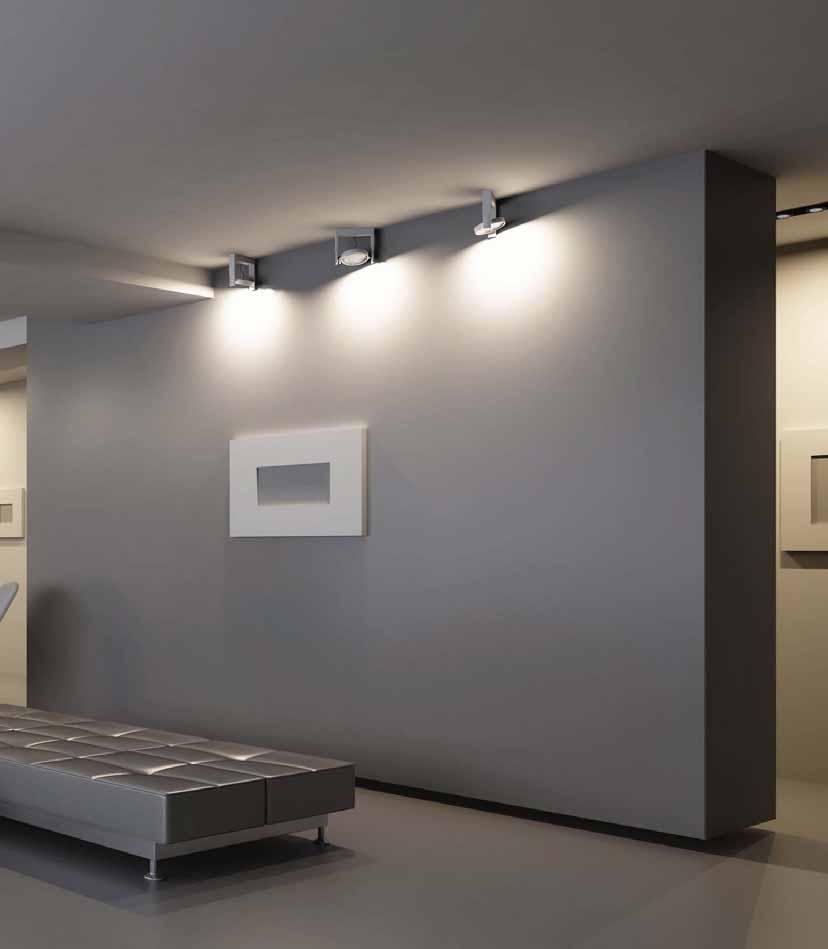
5 BRING ENERGY SAVINGS TO COMMON APPLICATIONS Small Offices Potential Energy Savings: 15 to 30% Bedrooms & Living Rooms Potential Energy Savings: Up to 50% Conference Rooms Potential Energy Savings: Up to 40% Open Offices Potential Energy Savings: Up to 30% Halls & Stairs Potential Energy Savings: 40 to 80% C5


6 Restrooms Potential Energy Savings: 50 to 70% Partitioned Restrooms Potential Energy Savings: 50 to 70% Lunch & Break Rooms Potential Energy Savings: 15 to 30% Storage Rooms Potential Energy Savings: 20 to 30% Exteriors Potential Energy Savings: 20 to 40% C6

7 PRODUCT MATRIX WIRELESS OCCUPANCY MODEL AND PAGE # WIRELESS OCCUPANCY SENSOR WALL SWITCH VACANCY SENSOR NEW NEW NEW NEW NEW NEW NEW NEW NEW NEW NEW EOPC-100 P. C13-14 EOSW-101 P. C15-16 EOSW-102 P. C15-16 EOSW-111 P. C15-16 EOSW-112 P. C15-16 EORS-101 P. C17-18 EORS-102 P. C17-18 EOHR-101 P. C19-20 EOHR-102 P. C19-20 EOKT-101 P. C13-14 EOKT-102 P. C13-14 MODEL AND PAGE # CS-50 P. C23-24 RS-150BA-N P. C25-26 CS-350-N P. C27-28 CH-250 P. C29-30 CU-250 P. C31-32 TECHNOLOGY PIR PIR PIR TECHNOLOGY VOLTAGE 120V 277V 347V 24VPP VOLTAGE 120V 277V 347V 24VPP UNIQUE FEATURES COVERAGE NEUTRAL REQ. RF; self-powered 1-relay; RF; Default Manual-on 2-relay;RF. Default Auto on to 50% 1-relay; RF; Default Manual-on 2-relay;RF. Default Auto on to 50% Self-powered wireless RF 1-button switch Self-powered wireless RF 2-button switch Handheld 1-button RF switch Handheld 2-button RF switch Sensor and 1-button RF switch Sensor and 2-button RF switch 360 ; up to 1200 ft ; up to 1200 ft ; up to 1200 ft 2 UNIQUE FEATURES COVERAGE NEUTRAL REQ. SO BLR CR HS SO BLR CR HS APPLICATIONS APPLICATIONS PIR Field Customizable 600 ft 2 PIR Nightlight 600 ft 2 PIR Dual Relay/Nightlight 600 ft 2 PIR Multi-Way 600 ft 2 Ultrasonic Multi-Way 600 ft 2 R R PR LBR SR PR LBR SR APPLICATION LEGEND SO-Small Offices BLR-Bedrooms & Living Rooms CR-Conference Rooms OO-Open Offices HS-Hallways & Stairs R-Restrooms PR-Partitioned Restrooms LBR-Lunch & Break Rooms SR-Storage Rooms E-Exteriors VOLTAGE LEGEND 115V 277V 120V 347V 240V 480V 24VPP = Power Pack Required C7


8 WALL SWITCH MODEL AND PAGE # CONVERTIBLE OCCUPANCY SENSOR RS-250 P. C33-34 RH-250 P. C35-36 RH-253 P. C37-38 OCCUPANCY SENSOR WS-250 ¹ P. C39-40 NEW NEW NEW NEW NEW WS-301 P. C41-42 PW-100 Series¹ P. C43-44,47-48 PW-101 ¹ P. C45-46 PW-103N ¹ P. C49-50 PW-200 ¹ P. C51-52 PW-201 P. C53-54 PW-203 ¹ P. C55-56 PW-301 P. C57-58 PW-302 P. C59-60 UW-100 Series¹ P. C61-64 UW-200 ¹ P. C65-66 DSW-100 ¹ P. C67-68 DSW-200 ¹ P. C69-70 DSW-301 P. C71-72 DSW-302 P. C73-74 DW-100 Series¹ P. C75-78 DW-103 ¹ P. C79-80 DW-200 ¹ P. C81-82 DW-203 ¹ P. C83-84 TECHNOLOGY VOLTAGE UNIQUE FEATURES COVERAGE NEUTRAL REQ. APPLICATIONS PIR Light Level Sensor 600 ft 2 PIR Multi-Way/Light Level Sensor 600 ft 2 PIR Multi-Way/Light Level Sensor 600 ft 2 PIR Light Level Sensor 900 ft 2 PIR Optional Connection 900 ft 2 PIR Low Profile, Selectable 1050 ft Operation Mode PIR Low Profile, Selectable 1050 ft Operation Mode PIR Nightlight, Multi-Way, 1050 ft Selectable Operation Mode PIR Dual Relay, 1050 ft Selectable Operation Mode PIR 120V 277V 347V 24VPP Dimmer, Vandal Resistant Lens 300 ft 2 SO BLR CR HS PIR Dual Relay, Multi-Way, 1050 ft Selectable Operation Mode PIR Optional Connection, 1050 ft Multi-way PIR Optional Connection, 1050 ft Multi-way, Dual Relay Ultrasonic High Sensitivity, Selectable 400 ft Operation Mode 2 Ultrasonic Dual Relay, Selectable 400 ft Operation Mode 2 Dual-Technology PIR Trigger, Selectable 1050 ft Operation Mode Dual-Technology Dual Relay, PIR Trigger 1050 ft 2 Dual-Technology Optional Connection, 1050 ft Multi-way Dual-Technology Optional Connection, 1050 ft Multi-way, Dual Relay Dual-Technology Premium Performance, 1050 ft Selectable Trigger Mode Dual-Technology Multi-Way, Selectable Trigger 1050 ft Mode Dual-Technology Dual Relay, Selectable Trigger 1050 ft Mode Dual-Technology Dual Relay, Multi-Way, 1050 ft Selectable Operation Mode R PR LBR SR Optional neutral connection ¹ Multiple voltage options available. Please visit for detailed product information. C8

9 PRODUCT MATRIX CEILING/ WALL MOUNT MODEL AND PAGE # CEILING MOUNT SENSOR CI-24² P. C87-88 WALL MOUNT SENSOR POWER PACKS ON/OFF AUXILIARY POWER PACKS CI-200/205² P. C89-90 CI-300/305² P. C91-92 CI-355¹ ² P. C93-94 W series² P. C95-96 UT-300/305² P. C97-98 WT series² P. C UT-355¹ ² P. C DT-300/305 P. C DT-355¹ P. C WPIR P. C CX-100/105² P. C CB-100² P. C DT-200/205² P. C TECHNOLOGY VOLTAGE UNIQUE FEATURES COVERAGE APPLICATIONS PIR 37mA, Low Profile ft 2 Isolated Relay, Light Level, PIR 20mA; 11mA, Low Profile ft 2 Isolated Relay, Light Level, PIR 20mA; 9mA, Low Profile ft 2 Line Voltage, PIR No Power Pack required ft 2 Ultrasonic Ultrasonic Ultrasonic Ultrasonic Dual Technology Dual Technology 16mA, 25kHz Isolated Relay, 40mA; 30mA, 40kHz 27mA; 30mA; 37mA; 40mA; Isolated Relay Line Voltage, No Power Pack required Isolated Relay, Light Level, 35mA, 43mA, Selectable Trigger Mode; Line Voltage, No Power Pack required ft 2, 90 ft linear ft ft 2, 90 ft linear ft ft ft 2 PIR Well Defined Coverage 300 ft 2 Isolated Relay, Light Level, 8mA, ft PIR 2, 19mA ft linear PIR Dual Technology MODEL AND PAGE # BZ-50 P. C BZ-50RC P. C BZ-150 P. C BD-100E-P P. C BD-100M P. C B347-P P. C BZ-480 P. C AT-120 P. C129 A120C-P P. C129 C120E-P P. C129 AT-277 P. C129 A277C-P P. C129 C277E-P P. C129 S120/277/347E-P P. C V 277V 347V 24VPP VOLTAGE 120V 277V 347V 480V Cold Location Isolated Relay, Light Level, 35mA, 43mA, Selectable Trigger Mode UNIQUE FEATURES Automatic On/Off Automatic On/Off Automatic or Manual On/Off Hold-On, Hold-Off, Din Rail Mount Manual-On, Din Rail Mount Automatic On/Off Two-Phase Form C 2-Relay Form C 2-Relay Two-Phase SO CR OO HS R 2000 ft 2, ft linear 2000 ft 2 APPLICATION LEGEND SO-Small Offices BLR-Bedrooms & Living Rooms CR-Conference Rooms OO-Open Offices HS-Hallways & Stairs R-Restrooms PR-Partitioned Restrooms LBR-Lunch & Break Rooms SR-Storage Rooms E-Exteriors VOLTAGE LEGEND 115V 277V PR LBR SR 120V 347V 240V 480V 24VPP = Power Pack Required ¹ Multiple voltage options available. Please visit for detailed product information. ² Models with different coverage options available. Please visit for detailed product information. C9


10 WALL SWITCH SENSOR DIMMERS VACANCY SENSOR/DIMMER MODEL AND PAGE # CD-250 P. C CONVERTIBLE OCCUPANCY SENSOR/DIMMER RD-250 P. C TECHNOLOGY LOAD TYPE VOLTAGE APPLICATIONS UNIQUE FEATURES COVERAGE 120V 277V SO BLR CR HS R PIR Incandescent Up to 600W 600 ft 2 PIR Incandescent Multi-Way, Up to 600W 600 ft 2 OCCUPANCY SENSOR/DIMMER PW-100D PW-101D P. C PIR Incandescent, Fluorescent Vandal Resistant Lens 600 ft 2 PLUG LOAD CONTROL MODEL AND PAGE # VOLTAGE TECHNOLOGY 120V UNIQUE FEATURES IDP-3050 P. C PIR Power strip w/ Personal Sensor for automatic control of Plug s OUTDOOR SENSOR MODEL AND PAGE # TECHNOLOGY LOAD TYPE VOLTAGE 120V 277V UNIQUE FEATURES COVERAGE EW-200 P. C PIR Incandescent Up to 600W 600 ft 2 EW P. C PIR Incandescent ACCESSORIES MODEL AND PAGE # UNIQUE FEATURES MB-1 P. C151 Up to 600W MB-2 P. C151 WC-1 P. C152 IT-200 P. C HS-100 P. C Low voltage HS-150 P. C Line voltage DAYLIGHTING CONTROLS MODEL AND PAGE # VOLTAGE 24VPP UNIQUE FEATURES APPLICATIONS SO HS LBR CR OO ON/OFF SWITCHING LS-102 P. C Automatic calibration; adjustable deadband, setpoints and time delay DIMMING CONTROL LS-301 P. C Handheld setup and occupant remotes; adjustable sliding setpoint control SERVICES P. C Comprehensive services include design, startup, onsite training and troubleshooting as necessary. C10


11 WIRELESS OCCUPANCY When re-wiring is not an option, wireless occupancy sensors, RF switches and wireless remotes are the perfect choice for energy efficiency upgrades. WattStopper s wireless products incorporate the company s single- and dual-relay options with code-compliant manual-on default operation. And these sustainable self-powered devices require no batteries, reducing waste and maintenance requirements. Photovoltaics power the sensors, while remote switches harness kinetic energy. C11

12 C12

13 EOPC-100 Wireless RF PIR Occupancy Sensor Self-powered extended range ceiling mount sensor Photovoltaic panels power sensor; no batteries required Transmitter for wireless communication with RF wall switches Works with 1- and 2-relay RF wall switches Reversible snap mounting disc Adds energy code compliance without the need for rewiring PROJECT LOCATION/TYPE Wireless Sensors Product Overview Description The EOPC-100 Wireless RF PIR Occupancy Sensor works with EOSW-100 Series RF Wall Switches to turn lights on and off based on occupancy. The sensor mounts on the ceiling and provides 360 passive infrared coverage. Operation EOPC-100 wireless sensors operate on power supplied by two photovoltaic panels capable of reaching a full charge in 6 hours when the ambient light level is 20 footcandles (215 lux). Each sensor can be paired with multiple loads controlled by RF wall switches. Paired loads configured for automatic-on operation turn on when a sensor transmits an RF signal that it has detected occupancy. As long as the sensor detects occupany it continues transmitting signals to the paired wall switch receivers. All paired loads turn off when no occupancy has been detected for the duration of the selected time delay. RF Communications The EOPC-100 sensor includes a non-directional helical antenna, so the sensor does not need to be oriented in a specific direction during installation. The RF (radio frequency) communication range is approximately 50' to 100', depending on product placement. Applications Wireless RF occupancy sensors are ideal for retrofit applications where it is difficult to install wiring to a ceiling mount sensor. The extended range EOPC-100 sensors are perfect for applications including small conference rooms, private offices, executives office, hallways and storage rooms. They detect minor motion up to 15' away and major motion up to 22' away when mounted at 8'. Coverage depends on a clear line of sight to the motion. Features Wireless RF occupancy sensors work with EOSW-100 Series RF wall switches Detection Signature Processing to eliminate false triggers and provide immunity to RFI and EMI Trim pot for sensitivity adjustment Test mode allows quick and easy set up Includes plate for mounting to single- or double-gang junction boxes or ceiling tile Reversible magnetic/adhesive disc for surface mounting Sensor coverage tested to NEMA Guide Publication WD C13
14 Specifications Powered by 2 photovoltaic panels; operates for up to 72 hours in total darkness Photovoltaic panel operating range: footcandles ( lux) Optional battery (CR2032, or equivalent) Multilevel Fresnel lens provides 360 coverage Adjustable PIR sensitivity Pairs with RF Wall Switch(es) Frequency: 902 MHz, helical antenna Mounting options: ceiling tile, junction box, surface mount (adhesive or magnetic) Operating conditions: for indoor use only; F (0-55 C); 5-95% RH, non condensing UL and cul listed FCC part 15 compliant Five year warranty Dimensions & Controls Dimensions 3.43" (87mm) 4.92" (125mm) Product Controls Test Button Pairing Button Sensitivity Trimpot Battery Tray 1.26" (32mm) Mounting Surface Mounting Options Coverage Reversable mounting disc One side is a supermagnet for mounting to metal, reverse side acts as foam tape for mounting to non-metal surfaces Coverage Patterns Mounting disc Snap mounting disc to mounting insert on back of sensor, magnet end face up. Snap magnet to surface. Major motion: Up to 44 diameter coverage when mounted at 8 Minor motion: Up to 30 diameter coverage when mounted at at 8 Wireless Sensors 44' 13.4m 0' Ordering Information Pub. No rev. 8/2013 8' 22' 13' 7' 3' 0' 3' 7' 13' 22' Catalog No. Color Description Coverage EOPC-100 EOKT-101-W EOKT-102-W Wireless self powered RF PIR occupancy sensor Wireless RF sensor 1 load kit (EOPC-100 and EOSW- 101-W single relay RF wall switch, no neutral) Wireless RF sensor 2 load kit (EOPC-100 and EOSW- 102-W dual relay RF wall switch, no neutral) 360 ; up to 1200 ft 2 (111.5 m 2 ) Order wall plate separately for switch in kits C14
 PROJECT")

15 EOSW-100 Series RF Wall Switches Single and dual relay 120/277 VAC RF-enabled switches Receiver for wireless communication with RF occupancy sensors and remote switches Default settings for most energy efficient operating mode out of the box Replace standard wall switches for energy code compliance without the need for rewiring s can be assigned to either button (dual relay switches) PROJECT LOCATION/TYPE Wireless Sensors Product Overview Description EOSW-100 Series RF Wall Switches work with EOPC-100 wireless occupancy sensors, and optional EORS-100 and EOHR-100 remote switches, to turn lights on and off based on occupancy. Models are available to control one or two switched legs in applications with or without neutral wires at the switch box. Operation Both single and dual relay RF wall switches fit in single gang junction boxes for direct control of one or two loads. Each wall switch can be paired with one or more EOPC-100 wireless sensors for occupancy-based control. By default, single relay wall switches operate in manual-on/automaticoff mode. Dual relay switches are factory set for auto-on to 50%; relay 1 is automatic on/off, and relay 2 is manual-on/automatic-off. When occupancy is no longer detected and the time delay elapses, lights automatically turn off. These sequences of operation, and other default settings, may be changed using hidden configuration buttons. Control Options and RF Communications EOSW-100 RF dual relay switches allow for separate pairing of each controlled load (relay) to the integral switch buttons. Additionally, each load may be paired with selected wireless occupancy sensors and selected buttons on RF remote switches. The RF transmission range is approximately 50' to 150' depending on product placement. Applications RF wall switches are ideal for retrofit applications with or without neutral wires where the switch location is not suitable for sensing occupancy, and it is difficult to install a wired ceiling sensor. Paired with wireless occupancy sensors, EOSW- 100 RF switches are perfect for retofiting small conference rooms, private offices, executives office, hallways and storage rooms. Features RF wall switches work with EOPC-100 wireless occupancy sensors Zero-crossing for long relay life Choice of manual-on or auto-on operation EOSW-111 and EOSW-112 comply with 2011 NEC requirements Selectable time delay Test mode allows quick and easy set up Compatible with decorator wall plates C15
16 Specifications 120/277VAC; 60 Hz rating, per 120VAC, 800W ballast, LED driver, ELV, MLV or tungsten, or 1/6hp motor (EOSW-10x, 15W minimum for load 277VAC, 1200W ballast, LED driver, ELV or MLV (EOSW-10x, 30W minimum for load 1) Relay Type: Form A latching relay 1 or 2 load buttons, each with LED status indicator Time Delays: 5, 15, 30 minutes (default 15 min.) Memory: Stores up to 10 transmitter IDs Frequency: 902MHz, integrated whip antenna Operating conditions: for indoor use only; 5-95% RH, non condensing Operating temperature: EOSW-10x: F (0-40 C); EOSW-11x: F (0-55 C) UL and cul listed FCC part 15 compliant Five year warranty Controls & Settings Product Dimensions and Controls 4.15" (105.3mm) 1.75" (44.4mm) 1.31" (33.3mm) Green Time Delay LEDs (3) Time Delay Button Green Operating Mode LEDs (2) Operating Mode Button Air Gap Release Button (EOSW-10x only) Blue Status LED Button Green Pairing LED Pairing Button Button Configuration Button Air Gap Button (EOSW-10x only) Wiring Diagrams Dual relay switch, no neutral EOSW-102 Dual relay switch, with neutral wire EOSW-112 Ordering Information Pub. No rev. 8/2013 Line Ground Green EOSW-101-W EOSW-101-LA Lt. Almond EOSW-101-I Ivory EOSW-101-G Grey EOSW-101-B EOSW-102-W EOSW-102-LA Lt. Almond EOSW-102-I Ivory EOSW-102-G Grey EOSW-102-B EOSW-111-W EOSW-111-LA Lt. Almond EOSW-111-I Ivory EOSW-111-G Grey EOSW-111-B EOSW-112-W EOSW-112-LA Lt. Almond EOSW-112-I Ivory EOSW-112-G Grey EOSW-112-B Order wall plate separately. Brown Primary Secondary Note: 1 relay switches are equipped with a red wire for a single load Line Ground Green Brown Primary Secondary Catalog No. Color Description Voltage Rating, per relay Single relay RF wall switch, no neutral Dual relay RF wall switch, no neutral Single relay RF wall switch, with neutral Dual relay RF wall switch, with neutral 120/277 VAC; 60 Hz 120VAC, W or 277VAC, W 120VAC, 0-800W or 277VAC, W s 1 & 120VAC, 0-800W or 277VAC, W Wireless Sensors C16

.")
17 EORS-100 Series Self-powered RF Remote Switches Wireless 1- and 2-button wall switches Mount in standard J-box Transmitter for wireless communication with RF wall switches Work with 1- and 2-relay RF wall switches Provide multi-way control with no wiring or batteries Radio transmission range up to 150' PROJECT LOCATION/TYPE Wireless Sensors Product Overview Description EORS-100 Series remote switches provide wireless remote control of lighting loads wired to EOSW-100 Series RF Wall Switches. They do not require any electrical connections or any batteries for operation. Models are available with one or two control buttons in a single-gang device. Operation Prior to use, each control button on an EORS- 100 remote switch must be paired with selected load(s). The remote switches operate using kinetic energy generated when a user pushes a control button. The button action transmits an RF signal to the paired RF Wall Switch(es) connected to the controlled load(s) to toggle the load(s) on or off. RF Communications The RF transmission range is approximately 50' to 150', depending on product placement. Applications Self-powered remote switches are ideal for retrofit applications where rewiring is prohibitive. Paired with RF wall switches and wireless occupancy sensors, EORS-100 remote switches are perfect for retofiting small conference rooms, private offices, executives office, hallways and storage rooms. Features Remote switches work with EOSW-100 RF wall switches Provide multi-way control without wires Self powered switches do not require batteries Compatible with decorator wall plates C17
18 Specifications Self-powered when switch is pressed 1 or 2 control buttons Pair with RF Wall Switch(es) Frequency: 902 MHz, integrated whip antenna Operating conditions: for indoor use only; F (0-40 C); 5-95% RH, non condensing UL and cul listed FCC part 15 compliant Five year warranty Controls & Settings Product Dimensions and Controls EORS-101 EORS " (105mm) Control Buttons 1.69" (42.8mm) 0.75" (19mm) Mounting Diagram Mounting in Standard Electrical Box Armando to update image of wall plate EORS-101 Junction box Wireless Sensors Wall plate Ordering Information Catalog No. Color Description Voltage EORS-101-W EORS-101-LA EORS-101-I EORS-101-G EORS-101-B EORS-102-W EORS-102-LA EORS-102-I EORS-102-G EORS-102-B Lt. Almond Ivory Grey Lt. Almond Ivory Grey 1-button RF remote wall switch 2-button RF remote wall switch Self-powered when switch is pressed Order wall plate separately. Pub. No rev. 8/ C18
19 EOHR-100 Series Self-powered RF Handheld Remotes Wireless 1- and 2-button handheld or wall mount switches Transmitter for wireless communication with RF wall switches Work with 1- and 2-relay RF wall switches Provide multi-way control without wiring or batteries Radio transmission range up to 150' PROJECT LOCATION/TYPE Wireless Sensors Product Overview Description EOHR-100 Series handheld remotes provide wireless remote control of lighting loads wired to EOSW-100 Series RF Wall Switches. They do not require any electrical connections or any batteries for operation. Models are available with one or two control buttons. Operation Prior to use, each control button on an EOHR-100 remote must be paired with selected load(s). The remote switches operate using kinetic energy generated when a user pushes a control button. The button action transmits an RF signal to the paired RF Wall Switch(es) connected to the controlled load(s) to toggle the load(s) on or off. RF Communications The RF transmission range is approximately 50' to 150', depending on product placement. Applications Self-powered handheld remotes are ideal for mounting on wall surfaces without the need for a junction box, and for portable lighting control. Paired with RF wall switches and wireless occupancy sensors, EOHR-100 remote switches are perfect for retofitting small conference rooms, private offices, executives office, hallways and storage rooms. Features Handheld remotes work with EOSW-100 RF wall switches Provide multi-way control without wires Self powered switches do not require batteries Include holster for optional mounting C19
20 Specifications Controls & Settings Self-powered when switch is pressed 1 or 2 control buttons Pairs with RF Wall Switch(es) Frequency: 902 MHz, integrated whip antenna Product Dimensions and Controls Operating conditions: for indoor use only; F (0-40 C); 5-95% RH, non condensing FCC part 15 compliant Five year warranty EOHR-101 EOHR " (120mm) Control Buttons 1.97" (50mm) 0.87" (22.1mm) Mounting Diagram Mounting on Glass Wall Mounting Bracket EOHR-102 Wall Mount Use two screws to mount the EOHR-10x to a hard wall using the mounting bracket Double-backed foam tape Use the double-backed foam tape on the back of EOHR mounting bracket to mount to a glass wall Slide EOHR onto mounting bracket to secure Wireless Sensors Ordering Information Catalog No. Color Description Voltage EOHR-101-W EOHR-101-LA EOHR-101-I EOHR-101-G EOHR-101-B EOHR-102-W EOHR-102-LA EOHR-102-I EOHR-102-G EOHR-102-B Lt. Almond Ivory Grey Lt. Almond Ivory Grey 1-button RF handheld remote 2-button RF handheld remote Self-powered when switch is pressed Pub. No rev. 8/ C20


21 WALL SWITCH Occupancy sensors maximize energy savings by ensuring that lights are turned off when spaces are unoccupied. WattStopper s wall switch sensors provide convenient automatic-on or manual-on control and are packed with innovative features and options. Many models are available in line or low voltage for flexibility in placement and wiring. Sensors use passive infrared, ultrasonic and WattStopper s patented dual technology. C21
22 C22
 Vacancy Sensor provides automatic shutoff for single-pole lighting control applications.")
23 CS-50 PIR Wall Switch Vacancy Sensor Manual-on/automatic-off control Adjustable time delay LED status indicator Two-wire sensor; no neutral connection PROJECT LOCATION/TYPE Product Overview Description The CS-50 Passive Infrared (PIR) Vacancy Sensor provides automatic shutoff for single-pole lighting control applications. It is engineered to comply with specific provisions of California s Title energy code. Operation The CS-50 operates as a manual-on sensor. Users must press the pushbutton to turn on lighting. The CS-50 employs PIR technology to sense the difference between the infrared energy from a person in motion and the background space. It keeps lighting on as long as motion is detected and provides automatic shutoff, following a userselected time delay, when motion is no longer detected. Users may turn the lighting off manually. Adjustable Time Delay The CS-50 is shipped preset for a 30 minute time delay, and does not require any adjustment after installation. If desired, the time delay may be easily reduced to 25, 20, 15, 10 or 5 minutes or to 30 seconds. The time delay should be set relative to the anticipated duration of stay and level of activity in the room; 30 minutes for guest room and executive restroom, and 5 to 10 minutes for pantries and laundry rooms. Applications The CS-50 is ideal for many residential and light commercial applications where the switch location has an unobstructed line of sight of the room. It does not require a neutral wire in the switch box and may be used to switch lighting or fan motors. Features Replaces single-pole switches Adjustable time delay, 30 seconds to 30 minutes If enabled, status indicator blinks when motion is detected Low-profile styling Choice of five decorator colors; lens is colormatched to device Operates most common types of lighting or fan motors Relay-based switching No current leakage to load in off mode for safety Compatible with decorator wall plates CA Title 24 compliant C23
24 30min. Specifications 120 VAC, 60 Hz ratings: 0-600W incandescent, LED, fluorescent, compact fluorescent (CFL), magnetic low voltage (MLV) or electronic low voltage (ELV) or 1/6 hp motor Time delay settings: 30 seconds, 5, 10, 15, 20, 25, 30 minutes PIR coverage: 180, 600 ft 2 (56 m 2 ) LED to indicate motion detection 2.67 x 1.73 x 1.77 (68mm x 44mm x 45mm) L x W x D Operating conditions: F (0-55 C), 95% RH, non-condensing; for indoor use only UL and cul listed Five year warranty Installation & Wiring Wiring Diagram -> HOT (power from circuit box) -> LOAD (power to lamp or fan) Time Delay Motion Blink OFF 30sec. 20min. 5min. 10min r1 OPEN Green -> GROUND Adjustments & Coverage Ordering Information Accessing Adjustments Status LED Switch Time Delay Dial OPEN CS-50-W CS-50-I CS-50-LA CS-50-A CS-50-B Time 30min. Delay Status LED OFF 30sec. Ivory Light Almond Almond Order wall plate separately r1 Adjustment controls are located behind the front cover of the unit and are clearly labeled. OPEN 4.0' (1.2m) 120 VAC, 60 Hz floor 12' (3.7m) 25' (7.6m) 25' (7.6m) Catalog No. Color Description Voltage Rating Coverage PIR Wall Switch Vacancy Sensor Coverage Pattern 0-600W incandescent, LED, fluorescent, CFL, MLV, ELV or 1/6 hp motor 180, max. 600 ft 2 (56m 2 ) Pub. No rev. 5/ C24
25 RS-150BA-N PIR Wall Switch Vacancy Sensor with Nightlight Manual-on/automatic-off control Ideal for bathrooms Integral LED nightlight Fixed 30-minute time delay PROJECT LOCATION/TYPE Product Overview Description The RS-150BA-N Passive Infrared (PIR) Vacancy Sensor provides automatic shutoff for single-pole lighting control applications. It is engineered to comply with specific provisions of California s Title energy code. Operation The RS-150BA-N operates as a manual-on sensor. Users must press the on/off pushbutton to turn on lighting. The RS-150BA-N employs PIR technology to sense the difference between the infrared energy from a person in motion and the background space. It keeps lighting on as long as motion is detected and provides automatic shutoff, following a 30-minute time delay, when motion is no longer detected. Users may turn the lighting off manually. Integral Nightlight The integral nightlight helps preserve night vision by providing low-level illumination when the connected lighting is off. The nightlight uses energy-efficient LEDs. Applications The RS-150BA-N PIR Vacancy Sensor requires no adjustment and is ideal for bathroom and bedroom applications where the switch location has an unobstructed line of sight of the room. Features Complies with 2011 NEC requirements Replaces single-pole switches Fixed 30-minute time delay; no adjustment necessary Amber LED nightlight illuminates whenever connected load is off Lighted switch for visibility in darkened rooms Low-profile styling Choice of five decorator colors; lens is colormatched to device Operates most common types of lighting or fan motors Relay-based switching No current leakage to load in off mode for safety Compatible with decorator wall plates CA Title 24 compliant C25
26 Specifications 120 VAC, 60 Hz; neutral required ratings: 0-600W incandescent, LED, fluorescent, compact fluorescent (CFL), magnetic low voltage (MLV) or electronic low voltage (ELV) or 1/6 hp motor Fixed time delay: 30 minutes PIR coverage: 180, 600 ft 2 (56 m 2 ) 2.63 x 1.69 x 1.88 (67.8mm x 42.9mm x 47.8mm) L x W x D Operating conditions: F (0-55 C), 95% RH, non-condensing; for indoor use only UL and cul listed Five-year warranty Wiring & Controls Wiring Diagram Product Controls -> HOT (power from circuit box) -> LOAD (power to lamp or fan) TOP PIR sensor lens TOP LED nightlight INDOOR USE ONLY -> NEUTRAL On/off pushbutton Y INDOOR USE ONLY Coverage Coverage Pattern 12' (3.7m) Green -> GROUND Terminal 25' (7.6m) 4.0' (1.2m) floor 25' (7.6m) Ordering Information Catalog No. Color Description Voltage Rating Coverage RS-150BA-N-W RS-150BA-N-I RS-150BA-N-LA RS-150BA-N-A RS-150BA-N-B Ivory Lt. Almond Almond PIR Wall Switch Vacancy Sensor with Nightlight 120 VAC, 60 Hz 0-600W incandescent, LED, fluorescent, CFL, MLV, ELV or 1/6 hp motor 180, max. 600 ft 2 (56m 2 ) Order wall plate separately. Pub. No rev. 3/ C26
27 CS-350-N PIR Dual Relay Wall Switch Vacancy Sensor with Nightlight Manual-on/automatic-off control of two separate loads Ideal for bathrooms Integral LED nightlight Adjustable time delay PROJECT LOCATION/TYPE Product Overview Description The CS-350-N Passive Infrared (PIR) Dual Relay Vacancy Sensor provides automatic lighting shutoff for applications that require separate switching of two loads. It is engineered to comply with specific provisions of California s Title energy code. Operation The CS-350-N operates as a manual-on sensor. Users must press one or both of the on/off pushbuttons to turn on the connected loads. The CS-350-N employs PIR technology to sense the difference between the infrared energy from a person in motion and the background space. It keeps the loads on as long as motion is detected and provides automatic shutoff, following a userselected time delay, when motion is no longer detected. Users may turn the connected loads off manually. Integral Nightlight The integral nightlight helps preserve night vision by providing low-level illumination when the connected loads are off. The nightlight uses energy-efficient LEDs. Applications The CS-350-N PIR Dual Relay Vacancy Sensor is appropriate anywhere that manually-activated control of two loads from a single location is desired (e.g. in a bathroom to control the light and exhaust fan). It is also a suitable device for light commercial applications like small offices or storage areas. By providing control of two loads from a single gang device, the CS-350-N helps reduce wall clutter. Features Complies with 2011 NEC requirements Replaces standard switches for control of lighting and/or fans Contains two relays to control two independent lighting loads or circuits Adjustable time delay, 15 seconds to 30 minutes Amber LED nightlight illuminates whenever connected loads are off Lighted switch for visibility in darkened rooms Low-profile styling Choice of five decorator colors; lens is colormatched to device Operates most common types of lighting or fan motors Relay-based switching No current leakage to load in off mode for safety Compatible with decorator wall plates CA Title 24 compliant C27
28 09560r1 15 Specifications 120 VAC, 60 Hz; neutral required ratings: 0-600W incandescent, LED, fluorescent, compact fluorescent (CFL), magnetic low voltage (MLV) or electronic low voltage (ELV) or 1/6 hp motor Adjustable time delay from 15 seconds to 30 minutes PIR coverage: 180, 600 ft 2 (56 m 2 ) 2.63 x 1.69 x 1.88 (67.8mm x 42.9mm x 47.8mm) L x W x D Operating conditions: F (0-55 C), 95% RH, non-condensing; for indoor use only UL and cul listed Five-year warranty Wiring & Controls Wiring Diagram Brown/ -> #2 (power to lamp or fan #2) Product Controls Brown -> HOT (power from circuit box for load #2) TOP -> NEUTRAL TOP Lock Bar Time Delay Recommended time delay for residential use is 15 to 30 minutes. 30 Min. 15 Minutes Sec. Time Delay Adjustment Dial INDOOR USE ONLY -> LOAD (power to lamp or fan #1) -> HOT (power from circuit box) INDOOR USE ON LY Slide down ON/OFF Buttons Coverage Green -> GROUND Terminal Coverage Pattern 12' (3.7m) 25' (7.6m) 4.0' (1.2m) floor To access adjustment dial, gently pull the lock bar away from the switch face and slide the on/off buttons down. 25' (7.6m) Ordering Information Catalog No. Color Description Voltage Rating Coverage CS-350-N-W CS-350-N-I CS-350-N-LA CS-350-N-A CS-350-N-B Ivory Lt. Almond Almond PIR Dual Relay Wall Switch Vacancy Sensor with Nightlight 120 VAC, 60 Hz 0-600W incandescent, LED, fluorescent, CFL, MLV, ELV or 1/6 hp motor 180, max. 600 ft 2 (56m 2 ) Order wall plate separately. Pub. No rev. 3/ C28
 Multi-way Vacancy Sensor provides automatic lighting shutoff")
29 CH-250 PIR Multi-way Wall Switch Vacancy Sensor Manual-on/automatic-off control with multi-way capability Ideal for hallways, stairwells and large rooms with multiple entrances Lighted pushbutton for visibility in darkened rooms Adjustable time delay PROJECT LOCATION/TYPE Product Overview Description The CH-250 Passive Infrared (PIR) Multi-way Vacancy Sensor provides automatic lighting shutoff for a variety of applications including those with multiple switch locations. It is engineered to comply with specific provisions of California s Title energy code. Operation The CH-250 operates as a manual-on sensor. Users must press the pushbutton to turn on lighting. The CH-250 employs PIR technology to sense the difference between the infrared energy from a person in motion and the background space. It keeps lighting on as long as motion is detected and provides automatic shutoff, following a user-selected time delay, when motion is no longer detected. Users may turn the connected load off manually. Multi-way Operation A CH-250 connected to other CH-250s and/ or RH-253 Decorator Single Pole Momentary Switches provides true multi-way on/off control. An occupant simply presses the on/off pushbutton of any connected device to turn on the lighting. Lights remain on as long as one of the CH-250s continues to detect occupancy. The user may turn off the lighting by pressing the on/off button on any of the connected devices. If the room becomes vacant and lights are on, they will be switched off automatically following the time delay of the last CH-250 to detect occupancy. Applications CH-250s are appropriate for residential and light commercial applications where the switch location has an unobstructed line of sight of the room. Multiple CH-250s are ideal for hallways, stairwells and large rooms with multiple entrances, as each sensor expands the coverage area. Features Complies with 2011 NEC requirements Replaces single- or multi-pole switches Provides multi-way control when used with other CH-250s or RH-253s Adjustable time delay, 15 seconds to 30 minutes Lighted switch for visibility in darkened rooms Low-profile styling Choice of five decorator colors; lens is colormatched to device Operates most common types of lighting Relay-based switching No current leakage to load in off mode for safety Compatible with decorator wall plates CA Title 24 compliant C29
30 TOP 30 Suggested time delays Bath or Ded room: 30: min. Half or Stairway: 5-15 min 09560r1 15 qot Specifications 120 VAC, 60 Hz; neutral required ratings: 0-600W incandescent, LED, fluorescent, compact fluorescent (CFL), magnetic low voltage (MLV) or electronic low voltage (ELV) or 1/6 hp motor Time delay settings: 15 seconds, 5, 15, 30 minutes PIR coverage: 180, 600 ft 2 (56 m 2 ) 2.67 x 1.73 x 1.77 (68mm x 44mm x 45mm) L x W x D Operating conditions: F (0-55 C), 95% RH, non-condensing; for indoor use only UL and cul listed Five year warranty Installation & Wiring Wiring Diagrams Yellow-> TRAVELER 2 to AUX CH-250 -> LOAD (power to lamp or fan) -> TRAVELER 1 power from AUX CH-250 Yellow-> TRAVELER 2 to MASTER CH-250 HOT (power from circuit box) -> TRAVELER 1 power to MASTER CH-250 -> capped -> NEUTRAL -> NEUTRAL INDOOR USE ONLY GROUND TERMINAL GROUND TERMINAL MASTER CH-250 AUXILIARY CH-250 For single pole applications, cap off the yellow wire. Up to four multi-location sensors may be connected together. For details on connecting RH-253s for multi-location control, see the RH-253 cut sheet. Hot TOP TOP Controls & Coverage INDOOR USE ONLY MASTER CH-250 Yellow Ground Product Controls TOP INDOOR USE ON LY Min. 15 Min. Sec. 5 Min. Traveler 1 Traveler 2 Lock Bar Time Delay Adjustment Dial Slide down ON/OFF Buttons Yellow Ground INDOOR USE ONLY AUXILIARY CH-250 Coverage Pattern 12' (3.7m) 25' (7.6m) To access adjustment dial, gently pull the lock bar away from the switch face and slide the on/off button down. 4.0' (1.2m) floor 25' (7.6m) Ordering Information Catalog No. Color Description Voltage Rating Coverage CH-250-W CH-250-I CH-250-LA CH-250-A CH-250-B Ivory Light Almond Almond PIR Multi-way Wall Switch Vacancy Sensor 120 VAC, 60 Hz 0-600W incandescent, LED, fluorescent, CFL, MLV, ELV lighting load or 1/6 hp motor load 180, max. 600 ft 2 (56m 2 ) Order wall plate separately. Pub. No rev. 3/ C30

31 CU-250 Ultrasonic Multi-way Wall Switch Vacancy Sensor Manual-on/automatic-off control with multi-way capability Ideal for bathrooms, L-shaped rooms and spaces with obstructions Lighted pushbutton for visibility in darkened rooms Adjustable sensitivity and time delay PROJECT LOCATION/TYPE Product Overview Description The CU-250 Ultrasonic Multi-way Vacancy Sensor provides automatic lighting shutoff for a variety of applications including those with multiple switch locations. It is engineered to comply with specific provisions of California s Title energy code. Operation The CU-250 operates as a manual-on sensor. Users must press the pushbutton to turn on lighting. The CU-250 employs 40kHz high frequency ultrasound to sense motion within an enclosed space, and does not require a clear line of sight for proper operation. It keeps lighting on as long as motion is detected and provides automatic shutoff, following a user-selected time delay, when motion is no longer detected. Users may turn the connected load off manually. Multi-way Operation A CU-250 connected to other CU-250s and/ or RH-253 Decorator Single Pole Momentary Switches provides true multi-way on/off control. An occupant simply presses the on/off pushbutton of any connected device to turn on the lighting. Lights remain on as long as one of the CU-250s continues to detect occupancy. The user may turn off the lighting by pressing the on/off button on any of the connected devices. If the room becomes vacant and lights are on, they will be switched off automatically following the time delay of the last CU-250 to detect occupancy. Applications CU-250s are ideal for bathrooms, L-shaped rooms, storage areas and other applications where the sensor may have an obstructed view of the covered area. Features Complies with 2011 NEC requirements Replaces single- or multi-pole switches Provides multi-way control when used with other CU-250s or RH-253s Adjustable time delay, 15 seconds to 30 minutes Adjustable sensitivity Lighted switch for visibility in darkened rooms Low-profile styling Choice of five decorator colors Operates most common types of lighting Relay-based switching No current leakage to load in off mode for safety Compatible with decorator wall plates CA Title 24 compliant C31
32 09575r Min. 5 Min. 15 Specifications 120 VAC, 60 Hz; neutral required ratings: 0-600W incandescent, LED, fluorescent, compact fluorescent (CFL), magnetic low voltage (MLV) or electronic low voltage (ELV) or 1/6 hp motor Time delay settings: 15 seconds, 5, 15, 30 minutes Coverage: 180, 600 ft 2 (56 m 2 ) 2.67 x 1.73 x 1.77 (68mm x 44mm x 45mm) L x W x D Operating conditions: F (0-50 C); for indoor use only UL and cul listed Five year warranty Installation & Wiring Wiring Diagrams -> HOT (power from circuit box) Hot Yellow (not used) -> LOAD (power to lamp or fan) TOP Traveler 1 TOP TOP Yellow Traveler 2 Yellow INDOOR USE ONLY Ground Ground INDOOR USE ONLY INDOOR USE ONLY -> NEUTRAL MASTER CU-250 AUXILIARY CU-250 Industry standard switch cover plate (not provided) LY Green -> GROUND Terminal Up to four multi-location sensors may be connected together. For details on connecting RH-253s for multi-location control, see the RH-253 cut sheet. Controls & Coverage Product Controls max min Sensitivity TOP Min. INDOOR USE ON Sec. Time Delay LY Lock Bar Adjustment Dials Slide Down ON/OFF Button To access adjustment dials, gently pull the lock bar away from the switch face and slide the on/off buttons down. Coverage Pattern Minor Motion (hand motion) Major Motion (walking motion) 7.5 (2.2m) 10 (3.0m) Minor Motion 15 (4.5m) Major Motion 20 (6.1m) Ordering Information Catalog No. Color Description Voltage Rating Coverage CU-250-W CU-250-I CU-250-LA CU-250-A CU-250-B Ivory Light Almond Almond Ultrasonic Multiway Wall Switch Vacancy Sensor 120 VAC, 60 Hz 0-600W incandescent, LED, fluorescent, CFL, MLV, ELV lighting load or 1/6 hp motor load 180, max. 600 ft 2 (56m 2 ) Order wall plate separately. Pub. No rev. 3/ C32
33 RS-250 PIR Wall Switch Occupancy Sensor Automatic-off control Light level sensor for added energy savings when automatic-on operation is selected Adjustable time delay Lighted pushbutton for visibility in darkened rooms Choice of manual-on or automatic-on operation PROJECT LOCATION/TYPE Product Overview Description The RS-250 Passive Infrared (PIR) Occupancy Sensor provides automatic lighting shutoff for single-pole lighting control applications. It offers optional automatic lighting activation. Light Level Sensor When automatic-on operation has been selected, the adjustable light level sensor may be set to prevent lights from turning on automatically if sufficient daylight is present. Operation The RS-250 operates either as a manual- or automatic-on sensor. When in manual-on mode, users must press the pushbutton to turn on lighting. The RS-250 employs PIR technology to sense the difference between the infrared energy from a person in motion and the background space. It keeps lighting on as long as motion is detected and provides automatic shutoff, following a user-selected time delay, when motion is no longer detected. Users may turn the lighting off manually. Applications The RS-250 is ideal for many residential and light commercial applications where the switch location has an unobstructed line of sight of the room. It should be used in manual-on mode for small offices, bedrooms and bathrooms. Automatic-on mode may be selected for convenience in spaces such as laundry rooms, storage rooms or closets. C33 Features Complies with 2011 NEC requirements Replaces single-pole switches Adjustable time delay, 15 seconds to 30 minutes Lighted switch for visibility in darkened rooms If enabled, light level sensing prevents automatic-on when adequate daylight exists Low-profile styling Choice of five decorator colors; lens is colormatched to device Operates most common types of lighting Relay-based switching No current leakage to load in off mode for safety Compatible with decorator wall plates Compliant with Nonresidential CA Title 24 requirements
34 Manual Min. 2 Auto-ON 06689r1 5 Min. 15 Specifications 120 VAC, 60 Hz; neutral required ratings: 0-600W incandescent, LED, fluorescent, compact fluorescent (CFL), magnetic low voltage (MLV) or electronic low voltage (ELV) or 1/6 hp motor Adjustable time delay from 15 seconds to 30 minutes Adjustable light level setting from fc ( lux) for daylight sensing PIR coverage: 180, 600 ft 2 (56 m 2 ) 2.67 x 1.73 x 1.77 (68mm x 44mm x 45mm) L x W x D Operating conditions: F (0-55 C), 95% RH, non-condensing; for indoor use only UL and cul listed Five year warranty Installation & Wiring Wiring Diagram -> HOT (power from circuit box) -> LOAD (power to lamp or fan) TOP INDOOR USE ONLY -> NEUTRAL Y Green -> GROUND Terminal Controls & Coverage Product Controls max Light Level min TOP Mode Time Delay INDOOR USE ONLY Min. Sec. Lock Bar Mode but ton and adjustment trimpots Slide down ON/OFF Button Coverage Pattern 12' (3.7m) 25' (7.6m) To access adjustment dial, gently pull the lock bar away from the switch face and slide the on/off button down. 4.0' (1.2m) floor 25' (7.6m) Ordering Information Catalog No. Color Description Voltage Rating Coverage RS-250-W RS-250-I RS-250-LA RS-250-A RS-250-B Ivory Light Almond Almond PIR Wall Switch Convertible Occupancy Sensor 120 VAC, 60 Hz 0-600W incandescent, LED, fluorescent, CFL, MLV, ELV lighting load or 1/6 hp motor load 180, max. 600 ft 2 (56m 2 ) Order wall plate separately. Pub. No rev. 3/ C34
35 RH-250 PIR Multi-way Wall Switch Occupancy Sensor Automatic-off control with multi-way capability Ideal for hallways, stairwells and large rooms with multiple entrances Adjustable time delay Lighted pushbutton for visibility in darkened rooms Choice of manual-on or automatic-on operation PROJECT LOCATION/TYPE Product Overview Description The RH-250 Passive Infrared (PIR) Multi-way Occupancy Sensor provides automatic lighting shutoff for a variety of applications including those with multiple switch locations. It offers optional automatic lighting activation. Operation The RH-250 operates either as a manual- or automatic-on sensor. When in manual-on mode, users must press the pushbutton to turn on lighting. The RH-250 employs PIR technology to sense the difference between the infrared energy from a person in motion and the background space. It keeps lighting on as long as motion is detected and provides automatic shutoff, following a user-selected time delay, when motion is no longer detected. Users may turn the lighting off manually. When automatic-on operation has been selected, the adjustable light level sensor may be set to prevent lights from turning on automatically if sufficient daylight is present. Multi-way Operation An RH-250 connected to other RH-250s and/ or RH-253 Decorator Single Pole Momentary Switches provides true multi-way on/off control. An occupant simply presses the on/off pushbutton of any connected device to turn on the lighting. Lights remain on as long as one of the RH-250s continues to detect occupancy. The user may turn off the lighting by pressing the on/off button on any of the connected devices. If the room becomes vacant and lights are on, they will be switched off automatically following the time delay of the last RH-250 to detect occupancy. Applications RH-250s are ideal for applications where the switch location has an unobstructed line of sight of the room. Multiple RH-250s can be used for lighting control in hallways, stairwells and large rooms with multiple entrances, as each sensor expands the coverage area. C35 Features Complies with 2011 NEC requirements Replaces single- or multi-pole switches Provides multi-way control when used with other RH-250s or RH-253s Adjustable time delay, 15 seconds to 30 minutes Lighted switch for visibility in darkened rooms If enabled, light level sensing prevents automatic-on when adequate daylight exists Low-profile styling Choice of five decorator colors; lens is colormatched to device Operates most common types of lighting Relay-based switching No current leakage to load in off mode for safety Compatible with decorator wall plates Compliant with Nonresidential CA Title 24 requirements
36 TOP Manual Min. 2 Auto-ON 06689r1 5 Min. 15 qot Specifications 120 VAC, 60 Hz; neutral required ratings: 0-600W incandescent, LED, fluorescent, compact fluorescent (CFL), magnetic low voltage (MLV) or electronic low voltage (ELV) or 1/6 hp motor Time delay settings: 15 seconds, 5, 15, 30 minutes Adjustable light level setting from fc ( lux) for daylight sensing PIR coverage: 180, 600 ft 2 (56 m 2 ) 2.67 x 1.73 x 1.77 (68mm x 44mm x 45mm) L x W x D Operating conditions: F (0-55 C), 95% RH, non-condensing; for indoor use only UL and cul listed Five year warranty Installation & Wiring Wiring Diagrams Yellow-> TRAVELER 2 to AUX RH-250 -> LOAD (power to lamp or fan) -> TRAVELER 1 power from AUX RH-250 Yellow-> TRAVELER 2 to MASTER RH-250 HOT (power from circuit box) -> TRAVELER 1 power to MASTER RH-250 -> capped -> NEUTRAL -> NEUTRAL INDOOR USE ONLY GROUND TERMINAL GROUND TERMINAL MASTER RH-250 AUXILIARY RH-250 For single pole applications, cap off the yellow wire. Up to four multi-location sensors may be connected together. For details on connecting RH-253s for multi-location control, see the RH-253 cut sheet. Hot 120V/60Hz TOP TOP Controls & Coverage INDOOR USE ONLY MASTER RH-250 Yellow Ground Product Controls max Light Level min TOP Mode Time Delay INDOOR USE ONLY Min. Sec. Lock Bar Slide down ON/OFF Button Traveler 1 Traveler 2 Mode but ton and adjustment trimpots Yellow Ground INDOOR USE ONLY AUXILIARY RH-250 Coverage Pattern 12' (3.7m) 25' (7.6m) To access adjustment dial, gently pull the lock bar away from the switch face and slide the on/off button down. 4.0' (1.2m) floor 25' (7.6m) Ordering Information Catalog No. Color Description Voltage Rating Coverage RH-250-W RH-250-I RH-250-LA RH-250-A RH-250-B Ivory Light Almond Almond PIR Multi-way Wall Switch Convertible Occupancy Sensor 120 VAC, 60 Hz 0-600W incandescent, LED, fluorescent, CFL, MLV, ELV lighting load or 1/6 hp motor load 180, max. 600 ft 2 (56m 2 ) Order wall plate separately. Pub. No rev. 3/ C36
37 RH-253 Decorator Single Pole Momentary Switch On/off switch for multi-way operation of occupancy and vacancy sensors Ideal for stairways, hallways, large spaces and bathrooms with multiple entrances Permits control from up to four locations PROJECT LOCATION/TYPE Product Overview Description The RH-253 is a single pole momentary switch for on/off control. It is typically used with multi-way occupancy and vacancy sensors for applications requiring multiple switch locations. Applications RH-253 switches provide economical control for three-, four- and multi-way lighting applications. Use RH-253s where additional sensor coverage is not needed, such as in a Jack and Jill bathroom. Operation Users tap the switch to turn connected lighting on or off. The RH-253 provides true multi-way on/off control when connected to one or more CH-250, CU-250, CD-250, RH-250 or RD-250 wall switch sensors. Features Replaces three-way or four-way switches when used with multi-way sensors Works with CH-250, CU-250 and RH-250 sensors and CD-250 and RD-250 sensor dimmers. Low-profile styling Choice of five decorator colors Compatible with decorator wall plates C37
38 Specifications 120 VAC, 60 Hz 2.67 x 1.73 x 1.77 (68mm x 44mm x 45mm) L x W x D Operating conditions: F (0-55 C), 95% RH, non-condensing; for indoor use only UL and cul listed Five year warranty Installation & Wiring Installation Wiring for Multi-way Sensor Operation RH-253 Hot TRAVELER 1 to RH-250 HOT (power from circuit box) TOP Yellow Traveler 1 (Hot) Traveler 2 Traveler 1 Traveler 2 INDOOR USE ONLY Ground Ground MASTER RH-250 GROUND TERMINAL TRAVELER 2 to RH-250 Traveler 1 Traveler 2 Traveler 1 Traveler 2 RH-253 Ground Ground RH-253 RH-253 The RH-253 may be used with the RH-250, as shown in these drawings, or with a CH-250, CD-250, CU-250 or RD-250 multi-way sensor in place of the RH-250. Applications Bedroom, Jack & Jill Bathroom, and Stairway Applications ML ML Bedroom 1 Stairway ML RH-253 ML Bathroom ML RH-253 Bedroom 2 Key ML - Surface mounted decorative incandescent fixture ML - Represents multi-way sensor (CD-250, CH-250, CU-250, RD-250, or RH-250) - Represents connection between sensors and/or momentary switches Ordering Information Catalog No. Color Description Voltage Rating Coverage RH-253-W RH-253-I RH-253-LA RH-253-B Ivory Light Almond Decorator Single Pole Momentary Switch 120 VAC, 60 Hz N/A N/A Order wall plate separately. Pub. No rev. 3/ C38
39 WS-250 Passive Infrared Wall Switch Occupancy Sensor 180 coverage, maximum of 900 ft 2 Button provides positive tactile feedback Shallow (1 ) back housing and flying leads for easy installation Dual voltage model, 120/277 VAC Compatible with all electronic ballasts Built-in light level sensor PROJECT LOCATION/TYPE Product Overview Features Description The WS-250 Passive Infrared (PIR) Wall Switch Sensor turns lighting on and off based on occupancy and ambient light level. It replaces existing wall switches and fits behind a standard decorator wall plate. Operation The WS-250 utilizes advanced PIR technology to detect occupancy. Detection occurs when the WS-250 senses the difference between infrared energy from a human body in motion and the background space. Lighting automatically turns on when occupancy is detected. After a user-specified length of time when no occupancy is detected, lighting automatically switches off. The sensor can also be used with line voltage switches for multilevel lighting. Pulse Count Processing eliminates false offs without reducing sensitivity Detection Signature Processing eliminates false triggers; provides immunity to RFI and EMI Zero crossing circuitry reduces stress on the relay and results in increased sensor life Time delay adjustment from 30 seconds up to 30 minutes Adjustable unit sensitivity from 20% to 100% Light level sensor holds lights off when ambient lighting is above the preset level Light Level Sensor The WS-250 features a built-in light level sensor. This feature holds lighting systems off when natural light levels are above the preset level. Once lights are switched on, the sensor will not switch them off even if daylight levels increase. Using the light level feature is optional and the setting is adjustable by the user. Applications The WS-250 has the flexibility to work in a variety of applications including offices, conference rooms, break rooms and utility rooms. Energy savings for these areas can be as high as 60% since lighting will no longer remain on once the room is vacant. With a competitive price, low installation cost, and high energy savings, paybacks are usually well under two years. Custom two-tier Fresnel lens enhances detection at the desktop level Sensor coverage tested to NEMA Guide Publication WD Patented voltage drop protection For safety, there is no leakage to load in the off mode and sensor is safety grounded LED indicates occupancy detection Compatible with decorator wall plates Qualifies for ARRA-funded public works projects C39
40 Specifications Controls & Installation 120/277VAC, 60Hz, or 347VAC, 60Hz Time delay adjustable from 30 seconds up to 30 minutes Adjustable unit sensitivity from 20% to 100% Adjustable light level setting of 2 to 200 footcandles (21.5 to 2,153 lux) Compatible with all electronic ballasts and PL lamp ballasts Product Controls Auto-off Switch Coverage: Major motion 35 x 30 Minor motion 20 x 15 Dimensions: 2.6 x 1.7 x 1.55 (66.0mm x 43.1mm x 39.4mm) L x W x D UL and cul listed Five year warranty Installation Light Level Time Delay Sensitivity LED Fresnel Lens Factory settings: 30-minute time delay, maximum light level and sensitivity L T S MIN MAX - + Extremely shallow (1 ) back housing and 6 flying leads facilitate quick installation in standard wall box 1 Coverage & Wiring Coverage Pattern Major motion Minor motion PIR Coverage Single Level Lighting Line 35 (10.6m) Ground Ordering Information 20 (6.1m) 4 (1.2m) 0 15 (4.5m) 7.5 (2.2m) 20 (6.1m) For best performance, WattStopper recommends using this sensor in spaces no larger than 15 x 12. WS-250-W WS-250-W-U WS-250-LA WS-250-I WS-250-I-U WS-250-G WS-250-B WS W WS I WS G WS B Light Almond Ivory Gray Ivory Gray 35 (10.6m) Catalog No. Color Voltage Rating Order wall plate separately. -U = ARRA compliant. Product produced in the U.S. 120 VAC; 60 Hz or 277 VAC; 60 Hz 347 VAC; 60 Hz Manual Bi-level Lighting 120 VAC, W ballast or tungsten or 1/6 277 VAC W ballast W ballast Line Pub. No rev. 5/ C40

41 WS-301 Passive Infrared Wall Switch Occupancy Sensor 180 coverage, maximum of 900 ft 2 Optional neutral connection with break off tab to expose neutral terminals Shallow (1 ) back housing and flying leads for easy installation 120/277 VAC and 347 VAC models Built-in light level sensor Button provides positive tactile feedback PROJECT LOCATION/TYPE Product Overview Description The WS-301 Passive Infrared (PIR) Wall Switch Sensor turns lighting or fan loads on and off based on occupancy and ambient light level. The sensor replaces existing wall switches and fits behind a standard decorator wall plate. Operation The WS-301 senses the difference between infrared energy from a human body in motion and the background space to turn on lighting automatically when occupancy is detected. After a user-specified length of time when no occupancy is detected, lighting automatically switches off. The sensor can also be used with line voltage switches for multi-level lighting. Optional Connection The WS-301 sensor uses a patent pending Sense Technology. Any WS-301 sensor can be used for a two-wire or three wire application, either to work with existing wiring, or to meet local or national code requirements. An easy-to-break plastic tab covers neutral screw terminals. Once the sensor is connected to neutral it complies with all codes that restrict current leakage to ground. Applications The WS-301 is great for retrofit projects and has the flexibility to work in a variety of applications including offices, conference rooms, break rooms and utility rooms. Energy savings for these areas can be as high as 60% since lighting will no longer remain on once the room is vacant. With a competitive price, low installation cost, and high energy savings, paybacks are usually well under two years. Features Complies with 2011 NEC requirements Zero crossing circuitry reduces stress on the relay and results in increased sensor life Adjustable time delay and sensitivity Custom two-tier Fresnel lens enhances detection at the desktop level Sensor coverage tested to NEMA Guide Publication WD Light level sensor holds lights off when ambient lighting is above the preset level Patented voltage drop protection For safety, there is no leakage to load in the off mode and sensor is safety grounded LED indicates occupancy detection C41
42 Specifications WS-301: 120/277VAC; 50/60Hz, 1/6 120VAC, W ballast, LED, and 277VAC, W ballast and LED WS : 347VAC; 50/60Hz, 1/6 hp; W ballast and LED Time delay adjustable from 30 seconds up to 30 minutes Adjustable sensitivity from 20% to 100% Adjustable light level setting of 10 to 200 footcandles (107.6 to 2,153 lux) Coverage: Major motion 35 x 30 Minor motion 20 x 15 Dimensions (L x W x D): - WS-301: 4.1 x 1.58 x 1 (104.6mm x 40.3mm x 26.5mm) - WS : 4.5 x 1.58 x 1.39 (114.36mm x 40.3mm x 35.5mm) UL and cul listed Five year warranty Controls & Installation Product Controls Option L T S MIN MAX - + Auto-off Switch Factory settings: 30-minute time delay, maximum light level and sensitivity 1" Light Level Time Delay Sensitivity LED Fresnel Lens Breakaway tab 6" flying leads for line, load and ground connections Optional neutral terminals behind breakaway tab Simple optional neutral connection allows installation in any 2-wire or 3-wire application. Coverage & Wiring Coverage Pattern Major motion Minor motion PIR Coverage 35 (10.6m) 20 (6.1m) 4 (1.2m) 0 15 (4.5m) 7.5 (2.2m) 20 (6.1m) For best performance, WattStopper recommends using this sensor in spaces no larger than 15 x (10.6m) Single Level Lighting Green Green Optional Manual Bi-level Lighting to Line Optional to Line Ordering Information Pub. No rev. 8/2013 Catalog No. Color Voltage Rating WS-301-W 120VAC; 120VAC, W ballast, LED, tungsten, 1/6 hp WS-301-LA Light Almond or WS-301-I WS-301-G WS-301-B WS W WS I WS G WS B Ivory Gray Ivory Gray 277VAC; 50/60Hz 347VAC; 50/60Hz 277VAC W ballast, LED, 1/6 hp W ballast & LED, 1/6 hp Order wall plate separately C42
43 PW-100 Passive Infrared Wall Switch Occupancy Sensor High sensitivity and dense coverage for exceptional performance Selectable operation, walk-through, test and presentation modes for increased energy savings and convenience No neutral wire required Color-matched lens and low profile for appealing design Defaults to Manual-ON operation for maximum energy savings PROJECT LOCATION/TYPE Product Overview Features Description The PW-100 passive infrared (PIR) wall switch sensor can turn lights OFF and ON based on occupancy. It is characterized by high sensitivity to small and large movements, appealing aesthetics, and a variety of features. Operation The PW-100 replaces existing wall switches and fits in a single gang junction box. It uses advanced PIR technology to detect occupancy and keep lighting ON when it is needed. Once the space is vacated and the time delay elapses, lights automatically turn OFF. DIP switch settings allow for a variety of control options such as Auto-ON operation, walk-through and test modes. Detection Signature Processing eliminates false triggers and provides immunity to RFI and EMI Zero-crossing for long relay life Vandal resistant lens combines precise coverage with durability Choice of Manual-ON or Auto-ON operation Selectable walk-through mode turns lights off three minutes after the room is initially occupied if no motion is detected after the first 30 seconds Test mode allows quick and easy adjustments Selectable audible and/or visual alerts for impending shutoff Manual-on Control Factory default operation is for Manual-ON, so that users turn lights on only when needed. This control strategy is proven to save more energy than Auto-ON, and is in ASHRAE If desired, the PW-100 may be reconfigured to turn lights on automatically. Applications The PW-100 sensor is well suited for small, enclosed spaces with clear line of sight of the occupant. Common applications include small office, small conference room and lunch/break rooms. In automatic mode, sensor returns automatically to Auto-ON after lights are turned off manually; ideal for presentations LED indicates occupancy detection Optional light level sensing with simple setup Service mode allows sensor to operate as a service switch in the unlikely event of a failure Sensor coverage tested to NEMA Guide Publication WD Compatible with decorator wall plates Qualifies for ARRA-funded public works projects C43
44 Specifications Controls & Settings PW-100: 120/277 VAC; 50/ VAC, W ballast or tungsten,1/6 277 VAC, W ballast PW : 347 VAC; 50/60Hz; W ballast Time delays: 5, 10, 15, 20, 25 or 30 minutes, walkthrough, test-mode Product Controls DELAY WALK PIR 50 % TRIGGE R ALERTS RLY 1 MAN RLY 2 MAN ON/OFF Button DIP Switches Detection LED Coverage: Major motion 35 x 30 Minor motion 20 x 15 Sensitivity adjustment: PIR (high/low) Dimensions: 2.73 x 1.76 x 1.83 (69.3mm x 44.7mm x 46.5mm) L x W x D UL and cul listed Five year warranty DIP Switch Settings Time Delay Test 5 minutes 10 minutes 15 minutes 20 minutes 25 minutes 30 minutes Service Walk-Through 4 Disabled Enabled ON Service bypasses occupancy & light level functions. Control the load manually using ON/OFF button. Time Delay Walk-Through Audible Alerts PIR Sensitivity PIR Sensitivity High Low, 50% ON Mode Visible Not Used Alerts Visible Alert Disabled Enabled Audible Alert Disabled Enabled ON Mode Auto On Manual On 7 8 Switch 9 is not used =ON =OFF =Factory Setting PIR Lens Coverage & Wiring Ordering Information Coverage Pattern Major motion Minor motion PIR Coverage 35 (10.6m) 20 (6.1m) 4 (1.2m) 0 15 (4.5m) 7.5 (2.2m) 20 (6.1m) 35 (10.6m) PW-100-W PW-100-W-U PW-100-LA PW-100-I PW-100-I-U PW-100-G PW-100-B Lt. Almond Ivory Grey 120/277 VAC; 50/60 Hz 2-wire sensor; no neutral connection PW W 347 VAC; 50/60 Hz PW LA Lt. Almond 2-wire sensor; no neutral PW I Ivory connection PW G Grey PW B Order wall plate separately. -U = ARRA compliant. Product produced in the U.S. Wiring Diagrams Line Ground Green/Yellow Ground Green Catalog No. Color Voltage Rating For best performance, WattStopper recommends using this sensor in spaces no larger than 15 x 120 VAC, W ballast or tungsten,1/6 277 VAC, W ballast W ballast Pub. No rev. 5/ C44
45 PW-101 Passive Infrared Wall Switch Occupancy Sensor High sensitivity and dense coverage for exceptional performance Selectable operation, walk-through, test and presentation modes for increased energy savings and convenience Includes neutral wire to meet NEC 2011 code Color-matched lens and low profile for appealing design Defaults to Manual-ON operation for maximum energy savings PROJECT LOCATION/TYPE Product Overview Features Description The PW-101 passive infrared (PIR) wall switch sensor can turn lights OFF and ON based on occupancy. It is characterized by high sensitivity to small and large movements, appealing aesthetics, and a variety of features. Operation The PW-101 replaces existing wall switches and fits in a single gang junction box. It uses advanced PIR technology to detect occupancy and keep lighting ON when it is needed. Once the space is vacated and the time delay elapses, lights automatically turn OFF. DIP switch settings allow for a variety of control options such as Auto-ON operation, walk-through and test modes. Detection Signature Processing eliminates false triggers and provides immunity to RFI and EMI Zero-crossing for long relay life Vandal resistant lens combines precise coverage with durability Choice of Manual-ON or Auto-ON operation Selectable walk-through mode turns lights off three minutes after the room is initially occupied if no motion is detected after the first 30 seconds Test mode allows quick and easy adjustments Selectable audible and/or visual alerts for impending shutoff Manual-on Control Factory default operation is for Manual-ON, so that users turn lights on only when needed. This control strategy is proven to save more energy than Auto-ON, and is in ASHRAE If desired, the PW-101 may be reconfigured to turn lights on automatically. Applications The PW-101 sensor is well suited for small, enclosed spaces with clear line of sight of the occupant. Common applications include small office, small conference room and lunch/break rooms. In automatic mode, sensor returns automatically to Auto-ON after lights are turned off manually; ideal for presentations LED indicates occupancy detection Optional light level sensing with simple setup Service mode allows sensor to operate as a service switch in the unlikely event of a failure required to meet NEC 2011 code Sensor coverage tested to NEMA Guide Publication WD Compatible with decorator wall plates C45
46 Specifications Controls & Settings PW-101: 120/277 VAC; 50/ VAC, W ballast or tungsten,1/6 277 VAC, W ballast Time delays: 5, 10, 15, 20, 25 or 30 minutes, walkthrough, test-mode Coverage: Major motion 35 x 30 Minor motion 20 x 15 Product Controls DELAY WALK PIR 50 % TRIGGE R ALERTS RLY 1 MAN RLY 2 MAN ON/OFF Button DIP Switches Detection LED Sensitivity adjustment: PIR (high/low) Dimensions: 2.73 x 1.76 x 1.83 (69.3mm x 44.7mm x 46.5mm) L x W x D UL and cul listed Five year warranty DIP Switch Settings Time Delay Test 5 minutes 10 minutes 15 minutes 20 minutes 25 minutes 30 minutes Service Walk-Through 4 Disabled Enabled ON Service bypasses occupancy & light level functions. Control the load manually using ON/OFF button. Time Delay Walk-Through Audible Alerts PIR Sensitivity PIR Sensitivity High Low, 50% ON Mode Visible Not Used Alerts Visible Alert Disabled Enabled Audible Alert Disabled Enabled ON Mode Auto On Manual On 7 8 Switch 9 is not used =ON =OFF =Factory Setting PIR Lens Coverage & Wiring Ordering Information Coverage Pattern Major motion Minor motion PIR Coverage 35 (10.6m) 20 (6.1m) 4 (1.2m) 0 15 (4.5m) 7.5 (2.2m) Order wall plate separately. 20 (6.1m) Lt. Almond Ivory Grey 35 (10.6m) 120/277 VAC; 50/60 Hz 3-wire sensor; requires neutral connection Wiring Diagrams Line Ground Green Catalog No. Color Voltage Rating PW-101-W PW-101-LA PW-101-I PW-101-G PW-101-B For best performance, WattStopper recommends using this sensor in spaces no larger than 15 x 120 VAC, W ballast or tungsten,1/6 277 VAC, W ballast Pub. No rev. 5/ C46
47 PW Passive Infrared Low Voltage Wall Switch Occupancy Sensor High sensitivity and dense coverage for exceptional performance Selectable operation, walk-through, test and presentation modes for increased energy savings and convenience Low voltage input Color-matched lens and low profile for appealing design Defaults to Manual-ON operation for maximum energy savings PROJECT LOCATION/TYPE Product Overview Description The PW passive infrared (PIR) low voltage wall switch sensor can turn lights OFF and ON based on occupancy. It is characterized by high sensitivity to small and large movements, appealing aesthetics, and a variety of features. Operation Factory default operation is for Manual-ON, so that users turn lights on only when needed. The PW uses advanced PIR technology to detect occupancy and keep lighting ON when it is needed. Once the space is vacated and the time delay elapses, lights automatically turn OFF. DIP switch settings allow for a variety of control options such as Auto-ON operation, walk-through and test modes. Low Voltage Low voltage wall switch sensors can offer advantages over line voltage models. Using an isolated form-c relay output, the PW sensor integrates seamlessly with VAV or other building systems for greater energy savings. Multiple PW sensors can also be connected on a single circuit and can switch loads that exceed the rating of a standard line voltage switch. In addition, low voltage sensor installations do not require the use of conduits reducing installation costs and making relocation easier. Applications The PW is the perfect choice for locations where line voltage wiring is not possible or for jurisdictions prohibiting the use of 277V switches. It is well suited for small enclosed spaces with clear line of sight of the occupant. Common applications include small offices, small conference rooms, and lunch/break rooms. C47 Features Detection Signature Processing eliminates false triggers and provides immunity to RFI and EMI Zero-crossing for long relay life Vandal resistant lens combines precise coverage with durability Choice of Manual-ON or Auto-ON operation Selectable walk-through mode turns lights off three minutes after the room is initially occupied if no motion is detected after the first 30 seconds Test mode allows quick and easy adjustments LED indicates occupancy detection Selectable audible and/or visual alerts for impending shutoff In automatic mode, sensor returns automatically to Auto-ON after lights are turned off manually; ideal for presentations Optional light level sensing with simple setup Service mode allows sensor to operate as a service switch in the unlikely event of a failure Sensor coverage tested to NEMA Guide Publication WD Compatible with decorator wall plates
48 Specifications Controls & Settings VDC, 24 VAC and halfwave rectified AC Current consumption: 20 ma PW contains single-pole, double-throw isolated relay rated for 1 30 VDC Time delays: 5, 10, 15, 20, 25 or 30 minutes, walk-through, test-mode Product Controls DELAY WALK PIR 50 % TRIGGE R ALERTS RLY 1 MAN RLY 2 MAN ON/OFF Button DIP Switches Detection LED Coverage: Major motion 35 x 30 Minor motion 20 x 15 Sensitivity adjustment: PIR (high/low) Dimensions: 2.73 x 1.76 x 1.83 (69.3mm x 44.7mm x 46.5mm) L x W x D UL and cul listed Five year warranty DIP Switch Settings Time Delay Test 5 minutes 10 minutes 15 minutes 20 minutes 25 minutes 30 minutes Service Walk-Through 4 Disabled Enabled ON Service bypasses occupancy & light level functions. Control the load manually using ON/OFF button. Time Delay PIR Sensitivity High Low, 50% ON Mode Visible Not Used Alerts Walk-Through Audible Alerts PIR Sensitivity Visible Alert Disabled Enabled Audible Alert Disabled Enabled ON Mode Auto On Manual On 7 8 Switch 9 is not used =ON =OFF =Factory Setting PIR Lens Coverage & Wiring Ordering Information Coverage Pattern Major motion Minor motion PIR Coverage 35 (10.6m) 20 (6.1m) 4 (1.2m) 0 15 (4.5m) 7.5 (2.2m) 20 (6.1m) 35 (10.6m) For best performance, WattStopper recommends using this sensor in spaces no larger than 15 x 12. Catalog No. Color Voltage PW W PW LA PW I PW G PW B Order wall plate separately. Lt. Almond Ivory Grey PW Low Voltage Wiring Hot VDC, 24 VAC and halfwave rectified AC () (Line) Power Pack +24 VDC Common Control Outputs Blue Normally closed contact Common Normally open contact Not used () Lighting Isolated Relay Outputs Pub. No rev. 5/ C48
49 PW-103N Passive Infrared Multi-way Wall Switch Occupancy Sensor with Nightlight High sensitivity and dense coverage for exceptional performance Optional nightlight with choice of three colors and two light levels Allows multi-way control from one of up to four control locations Selectable operation, walk-through, test and presentation modes for increased energy savings and convenience Color-matched lens and low profile for appealing design Defaults to Manual-ON operation for maximum energy savings PROJECT LOCATION/TYPE Product Overview Features Description The PW-103N passive infrared (PIR) multi-way wall switch sensor can turn lights OFF and ON based on occupancy. It provides high sensitivity to small and large movements, appealing aesthetics, a field selectable nightlight and a variety of features. Operation The PW-103N replaces existing wall switches and fits in a single gang junction box. It uses advanced PIR technology to detect occupancy and keep lighting ON when it is needed. Once the space is vacated and the time delay elapses, lights automatically turn OFF. DIP switch settings allow control options including Auto-ON operation, walkthrough and test modes. The PW-103N has an LED nightlight that can be set to high or low intensity and to amber, white or blue, or to off. Multiple PW-103N sensors may be used for control of one or more loads from up to four locations. Detection Signature Processing eliminates false triggers and provides immunity to RFI and EMI Zero-crossing for long relay life Vandal resistant lens combines precise coverage with durability Choice of Manual-ON or Auto-ON operation Selectable walk-through mode turns lights off three minutes after the room is initially occupied if no motion is detected after the first 30 seconds Test mode allows quick and easy adjustments Selectable audible and/or visual alerts for impending shutoff Multi-way Control The PW-103N offers true multi-way functionality. When connected sensors are in Manual-ON mode (default), an occupant must press the ON/OFF button of one of the sensors to turn the load ON. When sensors are in Auto-ON mode, the load will automatically turn ON when occupancy is detected by one of the sensors. Lights will remain ON as long as occupancy is detected. The last sensor to detect occupancy will turn the load OFF after the time delay has elapsed. In either operating mode, an occupant may turn the load OFF manually. Applications The PW-103N sensor is well suited for spaces with multiple doorways or switch locations, or spaces that would benefit from nightlighting. Common applications include private offices, small conference rooms, lunch/break rooms, individual restrooms and hotel guest bathrooms. In automatic mode, sensor returns automatically to Auto-ON after lights are turned off manually; ideal for presentations LED indicates occupancy detection Field selectable high or low intensity amber, white or blue nightlight Optional light level sensing with simple setup Service mode allows sensor to operate as a service switch in the unlikely event of a failure Sensor coverage tested to NEMA Guide Publication WD Compatible with decorator wall plates C49
50 Specifications Controls & Settings PW-103N: 120/277 VAC; 50/ VAC, W ballast or tungsten,1/6 277 VAC, W ballast Time delays: 5, 10, 15, 20, 25 or 30 minutes, walk-through, test-mode Coverage: Major motion 35 x 30 Minor motion 20 x 15 Product Controls DELAY WALK PIR 50 % TRIGGE R ALERTS RLY 1 MAN RLY 2 MAN ON/OFF Button DIP Switches Nightlight Detection LED Sensitivity adjustment: PIR (high/low) Dimensions: 2.73 x 1.76 x 1.83 (69.3mm x 44.7mm x 46.5mm) L x W x D UL and cul listed Five year warranty DIP Switch Settings Time Delay Test 5 minutes 10 minutes 15 minutes 20 minutes 25 minutes 30 minutes Service Walk-Through Enabled Disabled 4 ON Service bypasses occupancy & light level functions. Control the load manually using ON/OFF button. Time Delay PIR Sensitivity Low, 50% High On Mode Visible Nightlight Alerts Walk-Through Audible Alerts PIR Sensitivity 5 9 Audible Alert Enabled Disabled On Mode Manual On Auto On Visible Alert 6 Nightlight 9 Enabled Enabled Disabled Disabled =ON =OFF =Factory Setting 7 8 PIR Lens Coverage & Wiring Multi-way Wiring Diagram 1 Junction Box PW-103N () (Line) ( 1) Yellow (Traveler) Ground Junction Box PIR Coverage Major motion 120/277V 50/60Hz () (Line) PW-103N Coverage Pattern 35 (10.6m) 4 (1.2m) Major motion Minor motion PIR Coverage 20 (6.1m) 0 15 (4.5m) 7.5 (2.2m) 20 (6.1m) 35 (10.6m) For best performance in single location applications, WattStopper recommends using this sensor in spaces no larger than 15 x 12. In multi-way applications, each connected sensor expands the coverage area. Minor motion Ordering Information Catalog No. Color Voltage Rating PW-103N-W PW-103N-LA PW-103N-I PW-103N-G PW-103N-B Lt. Almond Ivory Grey 120/277 VAC; 50/ VAC, W ballast or tungsten,1/6 277 VAC, W ballast Order wall plate separately. Pub. No rev. 5/ C50
51 PW-200 Passive Infrared Dual Relay Wall Switch Occupancy Sensor High sensitivity and dense coverage for exceptional performance Selectable operation, walk-through, test and presentation modes for increased energy savings and convenience Two relays for control of two separate lighting loads or circuits Color-matched lens and low profile for appealing design Defaults to Auto-ON to 50% operation for maximum energy savings PROJECT LOCATION/TYPE C51 Product Overview Features Description The PW-200 passive infrared (PIR) wall switch sensor turns lights ON and OFF based on occupancy. It contains two relays for controlling two independent lighting loads or circuits, and a variety of features. Operation The PW-200 replaces existing wall switches and fits in a single gang junction box. Each of the PW-200 s relays can control a separate lighting load. It uses advanced PIR technology to detect occupancy and turn the first relay ON. Once the space is vacated and the time delay elapses, lights automatically turn OFF. Dual ON/OFF buttons allow the user to manually turn on and off each of the loads. DIP switch settings allow for a variety of control options such as Manual-ON or Auto-ON for each relay, walk-through and test modes. Detection Signature Processing eliminates false triggers and provides immunity to RFI and EMI Zero-crossing on both relays for long relay life Vandal resistant lens combines precise coverage with durability Choice of Manual-ON or Auto-ON operation, selectable for each relay Selectable walk-through mode turns lights off three minutes after the room is initially occupied if no motion is detected after the first 30 seconds Test mode allows quick and easy adjustments LED indicates occupancy detection Bi-Level Control The PW-200 features a built-in light level sensor that controls the second (secondary) relay. If adequate daylight is present, the sensor will hold secondary lights off until daylight levels drop, providing increased energy savings. The PW-200 satisfies energy codes requiring bi-level or daylight control switching. The two relays in the sensor give it the ability to control two lighting loads independently. This provides A/B switching where the user can achieve half-lighting (or another desired portion) from a single switch. Applications The PW-200 sensor is well suited for small, enclosed spaces with a clear line of sight of the occupant. In addition, its dual relays allow bi-level switching or control of a secondary load. Common applications include small office, small conference room and lunch/break rooms. Selectable audible and/or visual alerts for impending shutoff In automatic mode, sensor returns automatically to Auto-ON after lights are turned off manually; ideal for presentations Optional light level sensing with simple setup Service mode allows sensor to operate as a service switch in the unlikely event of a failure Sensor coverage tested to NEMA Guide Publication WD Compatible with decorator wall plates Qualifies for ARRA-funded public works projects
52 Specifications Controls & Settings PW-200: 120/277 VAC; 50/ VAC, W ballast or tungsten,1/6 277 VAC, W ballast PW : 347 VAC; 50/60 Hz; W ballast Time delays: 5, 10, 15, 20, 25 or 30 minutes, walk-through, test-mode Product Controls DELAY WALK PIR 50% VIS. ALERT AUD. ALERT RLY 1 MAN RLY 2 MAN ON/OFF Button DIP Switches Detection LED PIR Lens Coverage: Major motion 35 x 30 Minor motion 20 x 15 Sensitivity adjustment: PIR (high/low) Dimensions: 2.73 x 1.76 x 1.83 (69.3mm x 44.7mm x 46.5mm) L x W x D UL and cul listed Five year warranty DIP Switch Settings Time Delay Test 5 minutes 10 minutes 15 minutes 20 minutes 25 minutes 30 minutes override Walk-Through 4 Disabled Enabled Bypass occupancy & light level functions. s are manually controlled with PW-200 buttons. ON Time Delay Walk-Through Audible Alerts PIR Sensitivity PIR Sensitivity High Low, 50% =ON Visible Alerts Visible Alert Disabled Enabled =OFF Relay 1 Mode Relay 2 Mode Audible Alert Disabled 9 Enabled Relay 1 Mode 8 Auto On Manual On PW-200 ONLY Relay 2 Mode 9 Auto On Manual On Factory Settings: All models 1 PW-100 series 2 PW-200 series 2 1 Coverage & Wiring Ordering Information Coverage Pattern Major motion Minor motion PIR Coverage 35 (10.6m) 4 (1.2m) 20 (6.1m) 0 15 (4.5m) 7.5 (2.2m) 20 (6.1m) 35 (10.6m) For best performance, WattStopper recommends using this sensor in spaces no larger than 15 x 12. PW-200-W PW-200-W-U PW-200-LA PW-200-I PW-200-I-U PW-200-G PW-200-B PW W PW LA PW I PW G PW B Lt. Almond Ivory Grey 120/277 VAC; 50/60 Hz 2-wire sensor; no neutral connection Wiring Diagrams Line 1 Line 2 Ground Green Blue Ground Green/Yellow Catalog No. Color Voltage Rating Lt. Almond Ivory Grey Order wall plate separately. -U = ARRA compliant. Product produced in the U.S. 347 VAC; 50/60 Hz 2-wire sensor; no neutral connection Line Blue Ground Green/Yellow Ground Green Brown Primary Secondary Bi-level 120 VAC, W ballast or tungsten,1/6 277 VAC, W ballast W ballast Brown Primary Secondary Two circuit wiring Pub. No rev. 5/ C52
53 PW-201 Passive Infrared Dual Relay Wall Switch Occupancy Sensor High sensitivity and dense coverage for exceptional performance Two relays for control of two separate lighting loads or circuits Includes neutral wire to meet NEC 2011 code Selectable operation, walk-through, test and presentation modes for increased energy savings and convenience Color-matched lens and low profile for appealing design Defaults to Auto-ON to 50% operation for maximum energy savings PROJECT LOCATION/TYPE Product Overview Features Description The PW-201 passive infrared (PIR) wall switch sensor turns lights ON and OFF based on occupancy. It contains two relays for controlling two independent lighting loads or circuits, and a variety of features. Operation The PW-201 replaces existing wall switches and fits in a single gang junction box. Each of the PW-201 s relays can control a separate lighting load. It uses advanced PIR technology to detect occupancy and turn the first relay ON. Once the space is vacated and the time delay elapses, lights automatically turn OFF. Dual ON/OFF buttons allow the user to manually turn on and off each of the loads. DIP switch settings allow for a variety of control options such as Manual-ON or Auto-ON for each relay, walk-through and test modes. Detection Signature Processing eliminates false triggers and provides immunity to RFI and EMI Zero-crossing on both relays for long relay life Vandal resistant lens combines precise coverage with durability Choice of Manual-ON or Auto-ON operation, selectable for each relay Selectable walk-through mode turns lights off three minutes after the room is initially occupied if no motion is detected after the first 30 seconds Test mode allows quick and easy adjustments LED indicates occupancy detection Bi-Level Control The PW-201 features a built-in light level sensor that controls the second (secondary) relay. If adequate daylight is present, the sensor will hold secondary lights off until daylight levels drop, providing increased energy savings. The PW-201 satisfies energy codes requiring bi-level or daylight control switching. The two relays in the sensor give it the ability to control two lighting loads independently. This provides A/B switching where the user can achieve half-lighting (or another desired portion) from a single switch. Applications The PW-201 sensor is well suited for small, enclosed spaces with a clear line of sight of the occupant. In addition, its dual relays allow bi-level switching or control of a secondary load. Common applications include small office, small conference room and lunch/break rooms. Selectable audible and/or visual alerts for impending shutoff In automatic mode, sensor returns automatically to Auto-ON after lights are turned off manually; ideal for presentations required to meet NEC 2011 code Optional light level sensing with simple setup Service mode allows sensor to operate as a service switch in the unlikely event of a failure Sensor coverage tested to NEMA Guide Publication WD Compatible with decorator wall plates C53
54 Specifications Controls & Settings PW-201: 120/277 VAC; 50/ VAC, W ballast or tungsten,1/6 277 VAC, W ballast Time delays: 5, 10, 15, 20, 25 or 30 minutes, walk-through, test-mode Coverage: Major motion 35 x 30 Minor motion 20 x 15 Product Controls DELAY WALK PIR 50% VIS. ALERT AUD. ALERT RLY 1 MAN RLY 2 MAN ON/OFF Button DIP Switches Detection LED PIR Lens Sensitivity adjustment: PIR (high/low) Dimensions: 2.73 x 1.76 x 1.83 (69.3mm x 44.7mm x 46.5mm) L x W x D UL and cul listed Five year warranty DIP Switch Settings Time Delay Test 5 minutes 10 minutes 15 minutes 20 minutes 25 minutes 30 minutes override Walk-Through 4 Disabled Enabled Bypass occupancy & light level functions. s are manually controlled with PW-200 buttons. ON Time Delay Walk-Through Audible Alerts PIR Sensitivity PIR Sensitivity High Low, 50% =ON Visible Alerts Visible Alert Disabled Enabled =OFF Relay 1 Mode Relay 2 Mode Audible Alert Disabled 9 Enabled Relay 1 Mode 8 Auto On Manual On PW-200 ONLY Relay 2 Mode 9 Auto On Manual On Factory Settings: All models 1 PW-100 series 2 PW-200 series 2 1 Coverage & Wiring Ordering Information Coverage Pattern Major motion Minor motion PIR Coverage 35 (10.6m) 4 (1.2m) 20 (6.1m) 0 15 (4.5m) 7.5 (2.2m) 20 (6.1m) 35 (10.6m) For best performance, WattStopper recommends using this sensor in spaces no larger than 15 x 12. Wiring Diagrams Line 1 Line 2 Ground Green Blue Ground Green/Yellow Brown Primary Secondary Catalog No. Color Voltage Rating PW-201-W PW-201-LA PW-201-I Lt. Almond Ivory 120/277 VAC; 50/60 Hz 3-wire sensor; requires neutral 120 VAC, W ballast or tungsten,1/6 277 VAC, W ballast PW-201-G Grey PW-201-B Order wall plate separately. Line Blue Ground Green/Yellow Ground Green Brown Primary Secondary Bi-level wiring Two circuit wiring Pub. No rev. 5/ C54
55 PW-203 Passive Infrared Multi-way Dual Relay Wall Switch Occupancy Sensor High sensitivity and dense coverage for exceptional performance Two relays for control of two separate lighting loads Allows multi-way control from one of up to four control locations Selectable operation, walk-through, test and presentation modes for increased energy savings and convenience Color-matched lens and low profile for appealing design Defaults to Auto-ON operation for greatest energy savings PROJECT LOCATION/TYPE C55 Product Overview Features Description The PW-203 passive infrared (PIR) multi-way wall switch sensor turns lights ON and OFF based on occupancy. It contains two relays for controlling two independent lighting loads and a variety of features. Operation The PW-203 replaces existing wall switches and fits in a single gang box. Each of the PW-203 s relays can control a separate lighting load. It uses advanced PIR technology to detect occupancy and turn the first relay ON. Once the space is vacated and the time delay elapses, lights automatically turn OFF. Dual ON/OFF buttons allow the user to manually switch each of the loads, and each relay can be set for Manual-ON or Auto-ON. The PW-203 features a built-in light level sensor that controls the second relay. If adequate daylight is present, the sensor will hold the second relay off until daylight levels drop for increased energy savings. Detection Signature Processing eliminates false triggers and provides immunity to RFI and EMI Zero-crossing on both relays for long relay life Vandal resistant lens combines precise coverage with durability Choice of Manual-ON or Auto-ON operation, selectable for each relay Selectable walk-through mode turns lights off three minutes after the room is initially occupied if no motion is detected after the first 30 seconds Test mode allows quick and easy adjustments Multi-way Control Multiple PW-203 sensors may be connected for control from up to four locations, and provide true multi-way functionality. When Manual-ON mode is active, an occupant must press an ON/OFF button on one of the sensors to turn a load ON. When Auto-ON mode is active, the load will automatically turn ON when occupancy is detected by one of the sensors. Lights will remain ON as long as occupancy is detected. The last sensor to detect occupancy will turn the loads OFF after the time delay has elapsed. In either operating mode, an occupant may turn the load OFF manually. Applications The PW-203 sensor is well suited for spaces requiring bi-level lighting control, or control of two independent loads, that have multiple doorways or switch locations. Common applications include small offices, small conference rooms and lunch/ break rooms. Selectable audible and/or visual alerts for impending shutoff In automatic mode, sensor returns automatically to Auto-ON after lights are turned off manually; ideal for presentations LED indicates occupancy detection Optional light level sensing with simple setup Service mode allows sensor to operate as a service switch in the unlikely event of a failure Sensor coverage tested to NEMA Guide Publication WD Compatible with decorator wall plates
56 Specifications Controls & Settings 120/277 VAC; 50/ VAC, W ballast or tungsten,1/6 277 VAC, W ballast Time delays: 5, 10, 15, 20, 25 or 30 minutes, walk-through, test-mode Product Controls DELAY WALK PIR 50% VIS. ALERT AUD. ALERT RLY 1 MAN RLY 2 MAN ON/OFF Buttons DIP Switches Detection LED PIR Lens Coverage: Major motion 35 x 30 Minor motion 20 x 15 Sensitivity adjustment: PIR (high/low) Dimensions: 2.73 x 1.76 x 1.83 (69.3mm x 44.7mm x 46.5mm) L x W x D UL and cul listed Five year warranty DIP Switch Settings Time Delay Test 5 minutes 10 minutes 15 minutes 20 minutes 25 minutes 30 minutes Service Walk-Through 4 Disabled Enabled ON Service bypasses occupancy & light level functions. Control the load manually using ON/OFF button. Time Delay PIR Sensitivity High Low, 50% Relay 1 Mode Visible Relay 2 Mode Alerts Walk-Through Audible Alerts PIR Sensitivity Visible Alert Disabled Enabled Audible Alert Disabled Enabled Relay 1 Mode Auto On Manual On Relay 2 Mode Auto On Manual On =ON =OFF =Factory Setting Coverage & Wiring Multi-way Bi-level Wiring Diagram PW-203 () (Line) Blue (Line) ( 1) Brown ( 2) Yellow (Traveler) Ground Junction Box Junction Box PIR Coverage Major motion Minor motion 120/277V 50/60Hz () (Line) PW-203 Coverage Patterns Major motion Minor motion PIR Coverage 35 (10.6m) 4 (1.2m) 20 (6.1m) 0 15 (4.5m) 7.5 (2.2m) 20 (6.1m) 35 (10.6m) For best performance in single location applications, WattStopper recommends using this sensor in spaces no larger than 15 x 12. In multi-way applications, each connected sensor expands the coverage area. Ordering Information Catalog No. Color Voltage Rating PW-203-W PW-203-LA PW-203-I PW-203-G PW-203-B Lt. Almond Ivory Grey 120/277 VAC; 50/ VAC, W ballast or tungsten,1/6 277 VAC, W ballast Order wall plate separately. Pub. No rev. 5/ C56
57 PW-301 Passive Infrared Wall Switch Occupancy Sensor High sensitivity and dense coverage for exceptional performance Optional neutral connection with break off tab to expose neutral terminals Defaults to Manual-ON operation for maximum energy savings 120/277 VAC and 347 VAC models Color-matched lens and low profile for appealing design Allows multi-way control from one of up to four control locations PROJECT LOCATION/TYPE Product Overview Description The PW-301 passive infrared (PIR) wall switch sensor can turn lights OFF and ON based on occupancy. It is characterized by high sensitivity to small and large movements, appealing aesthetics, and a variety of features. Operation The PW-301 replaces existing wall switches and installs in a single gang junction box with or without either neutral wiring. Factory default operation is for Manual-ON, so that users turn lights on only when needed. It uses advanced PIR technology to detect occupancy and keep lighting ON when it is needed. Once the space is vacated and the time delay elapses, lights automatically turn OFF. DIP switch settings allow for a variety of control options such as Auto-ON operation, walkthrough and test modes. Multiple sensors may be used for control of one or more loads from up to four locations. Optional Connection The PW-301 sensor uses a patent pending Sense Technology. Any PW-301 sensor can be used for a two-wire or three wire application, either to work with existing wiring, or to meet local or national code requirements. An easy-to-break plastic tab covers neutral screw terminals. Once the sensor is connected to neutral it complies with all codes that restrict current leakage to ground. Applications The PW-301 sensor is great for retrofit projects and well suited for small, enclosed spaces with clear line of sight of the occupant. Common applications include small offices, small conference rooms and lunch/break rooms. Features Complies with 2011 NEC requirements Zero-crossing for long relay life Vandal resistant lens combines precise coverage with durability Selectable walk-through mode turns lights off three minutes after the room is initially occupied if no motion is detected after the first 30 seconds Test mode allows quick and easy adjustments Selectable audible and/or visual alerts for impending shutoff LED indicates occupancy detection In automatic mode, sensor returns automatically to Auto-ON after lights are turned off manually; ideal for presentations Optional light level sensing with simple setup Service mode allows sensor to operate as a service switch in the unlikely event of a failure Sensor coverage tested to NEMA Guide Publication WD Compatible with decorator wall plates C57
58 Specifications PW-301: 120/277VAC; 50/60Hz, 1/6 120VAC, W ballast, LED, and 277VAC, W ballast and LED PW : 347VAC; 50/60Hz, 1/6 hp; W ballast and LED Time delays: 5, 10, 15, 20, 25 or 30 minutes, walk-through, test-mode Coverage: Major motion 35 x 30 Minor motion 20 x 15 Sensitivity adjustment: PIR (high/low) Dimensions (L x W x D): - PW-301: 4.1 x 1.58 x 1.39 (104.6mm x 40.3mm x 35.5mm) - PW : 4.5 x 1.58 x 1.39 (114.36mm x 40.3mm x 35.5mm) UL and cul listed Five year warranty Controls & Settings Product Controls & Option DIP Switches Detection LED PIR Lens DELAY WALK PIR 50 % TRIGGE R ALERTS RLY 1 MAN RLY 2 MAN ON/OFF Button 6" flying leads for line, load, ground and multi-way connections DIP Switch Settings Time Delay Test/20 min 5 minutes 10 minutes 15 minutes 20 minutes 25 minutes 30 minutes Service Walk-Through Enabled Disabled 4 ON Service bypasses occupancy & light level functions. Control the load manually using ON/OFF button. Time Delay Visible Alerts Walk-Through Audible Alerts PIR Sensitivity PIR Sensitivity Low, 50% High Visible Alert 6 Enabled Disabled =ON =OFF Relay 1 Mode Relay 2 Mode Audible Alert 7 Enabled 9 Disabled Relay 1 Mode 8 Manual On 5 Auto On PW-302 ONLY Relay 2 Mode Manual On Auto On 9 Factory Settings: All models 1 PW-301 series 2 PW-302 series 1 2 Breakaway tab Simple optional neutral connection allows installation in any 2-wire or 3-wire application. Optional neutral terminals behind breakaway tab Coverage & Wiring Coverage Pattern Major motion Minor motion PIR Coverage 35 (10.6m) 20 (6.1m) 4 (1.2m) 0 15 (4.5m) 7.5 (2.2m) 20 (6.1m) 35 (10.6m) For best performance, WattStopper recommends using this sensor in spaces no larger than 15 x 12. Wiring Diagrams Line Line Ground Green Green Ground Green Green Yellow traveler Yellow (optional) Yellow Green Green (optional) Ground Multi-way wiring (optional) Ordering Information Pub. No rev. 8/2013 Catalog No. Color Voltage Rating PW-301-W 120VAC; 120VAC, W ballast, LED, tungsten, 1/6 hp PW-301-LA Lt. Almond or or PW-301-I Ivory 277VAC; 277VAC W ballast, LED, 1/6 hp PW-301-G Grey PW-301-B PW W 347VAC; 50/60Hz W ballast & LED, 1/6 hp PW LA Lt. Almond PW I Ivory PW G Grey PW B Order wall plate separately. C58
59 PW-302 Passive Infrared Dual Relay Wall Switch Occupancy Sensor High sensitivity and dense coverage for exceptional performance Optional neutral connection with break off tab to expose neutral terminals Two relays for control of two separate lighting loads or circuits 120/277 VAC and 347 VAC models Defaults to Auto-ON to 50% operation for maximum energy savings Allows multi-way control from one of up to four control locations PROJECT LOCATION/TYPE Product Overview Description The PW-302 passive infrared (PIR) wall switch sensor turns lights ON and OFF based on occupancy. It contains two relays for controlling two independent lighting loads or circuits, and a variety of features. Operation The PW-302 replaces existing wall switches and installs in a single gang junction box with or without either neutral wiring. Each of the PW-302 s relays can control a separate lighting load. The device uses advanced PIR technology to detect occupancy and turn the first relay ON. The other relay must be manually engaged to turn remaining lights on. Once the space is vacated and the time delay elapses, all lights automatically turn OFF. Dual ON/OFF buttons allow the user to manually turn on and off each of the loads. DIP switch settings allow for a variety of control options such as Manual-ON or Auto-ON for each relay, walkthrough and test modes. Multiple sensors may be used for control of one or more loads from up to four locations. Optional Connection The PW-302 sensor uses a patent pending Sense Technology. Any PW-302 sensor can be used for a two-wire or three wire application, either to work with existing wiring, or to meet local or national code requirements. An easy-to-break plastic tab covers neutral screw terminals. Once the sensor is connected to neutral it complies with all codes that restrict current leakage to ground. Applications The PW-302 sensor is great for retrofit projects and well suited for small, enclosed spaces with a clear line of sight of the occupant. In addition, its dual relays allow bi-level switching or control of a secondary load. Common applications include small office, small conference room and lunch/ break rooms. C59 Features Complies with 2011 NEC requirements Zero-crossing on both relays for long relay life Vandal resistant lens combines precise coverage with durability Selectable walk-through mode turns lights off three minutes after the room is initially occupied if no motion is detected after the first 30 seconds Test mode allows quick and easy adjustments LED indicates occupancy detection Selectable audible and/or visual alerts for impending shutoff In automatic mode, sensor returns automatically to Auto-ON after lights are turned off manually; ideal for presentations Optional light level sensor holds secondary lights off when ambient lighting is above the preset level Service mode allows sensor to operate as a service switch in the unlikely event of a failure Sensor coverage tested to NEMA Guide Publication WD Compatible with decorator wall plates
60 Specifications PW-302: 120/277VAC; 50/60Hz, 1/6 120VAC, 0-800W ballast, LED, and 277VAC, W ballast and LED PW : 347VAC; 50/60Hz, 1/6 hp; W ballast and LED Time delays: 5, 10, 15, 20, 25 or 30 minutes, walk-through, test-mode Coverage: Major motion 35 x 30 Minor motion 20 x 15 Sensitivity adjustment: PIR (high/low) Dimensions (L x W x D): - PW-302: 4.1 x 1.58 x 1.39 (104.6mm x 40.3mm x 35.5mm) - PW : 4.5 x 1.58 x 1.39 (114.36mm x 40.3mm x 35.5mm) UL and cul listed Five year warranty Controls & Settings Product Controls & Option DIP Switches Detection LED PIR Lens DELAY WALK PIR 50% VIS. ALERT AUD. ALERT RLY 1 MAN RLY 2 MAN ON/OFF Button Simple optional neutral connection allows installation in any 2-wire or 3-wire application. Breakaway tab 6" flying leads for line, load, ground and multi-way connections Optional neutral terminals behind breakaway tab DIP Switch Settings Time Delay Test/20 min 5 minutes 10 minutes 15 minutes 20 minutes 25 minutes 30 minutes Service Walk-Through Enabled Disabled 4 Service bypasses occupancy & light level functions. Control the load manually using ON/OFF button. Relay 1 Mode Time Delay Visible Relay 2 Mode Alerts Audible Alert ON Enabled Disabled Walk-Through Audible Alerts PIR Sensitivity PIR Sensitivity Low, 50% High Visible Alert Enabled Disabled =ON 5 6 =OFF Relay 1 Mode Manual On Auto On PW-302 ONLY Relay 2 Mode Manual On Auto On Factory Settings: All models 1 PW-301 series 2 PW-302 series 1 2 Coverage & Wiring Coverage Pattern Major motion Minor motion PIR Coverage 35 (10.6m) 4 (1.2m) 20 (6.1m) 0 15 (4.5m) 7.5 (2.2m) 20 (6.1m) 35 (10.6m) For best performance, WattStopper recommends using this sensor in spaces no larger than 15 x 12. Wiring Diagrams Line Ground Blue Green Green Line 1 Blue Green Green Ground Yellow Brown (optional) Ground Blue Green Green Bi-level and multi-way wiring Yellow Brown Line 2 (optional) Ground Blue Green Green Two circuit and multi-way wiring Brown (optional) Brown (optional) Primary Secondary Primary Secondary Ordering Information Catalog No. Color Voltage Rating PW-302-W PW-302-LA PW-302-I PW-302-G PW-302-B Lt. Almond Ivory Grey 120VAC; 50/60Hz or 277VAC; 120VAC, 0-800W ballast, LED, tungsten, 1/6 hp 277VAC W ballast, LED, 1/6 hp PW W 347VAC; 50/60Hz W ballast & LED, 1/6 hp PW LA Lt. Almond PW I Ivory PW G Grey PW B Order wall plate separately. Pub. No rev. 8/ C60
61 UW-100 Ultrasonic Wall Switch Occupancy Sensor High sensitivity for exceptional performance Selectable operation, walk-through, test and presentation modes for increased energy savings and convenience Defaults to Manual-ON operation for maximum energy savings Low profile design Part of a comprehensive line of PIR, Ultrasonic and Dual Technology wall switch sensors PROJECT LOCATION/TYPE Product Overview Description The UW-100 ultrasonic wall switch sensor can turn lights OFF and ON based on occupancy. It is characterized by high sensitivity to small and large movements, appealing aesthetics, and a variety of features. Operation The UW-100 fits in a single junction box. It uses high frequency (40kHz) ultrasound to detect occupancy and keep lighting ON when it is needed. Once the space is vacated and the time delay elapses, lights automatically turn OFF. DIP switch settings allow for a variety of control options such as Auto-ON operation, walk-through and test modes. Manual-on Control Factory default operation is for Manual-ON, so that users turn lights on only when needed. This control strategy is proven to save more energy than Auto-ON, and is in ASHRAE If desired, the UW-100 may be reconfigured to turn lights on automatically. Applications The UW-100 sensor is ideal for applications where the sensor may have a partially obstructed line of sight of the occupant. Common applications include individual restrooms, restrooms with two stalls and utility/storage rooms. C61 Features Complies with 2011 NEC requirements Detection Signature Processing eliminates false triggers and provides immunity to RFI and EMI Zero-crossing for long relay life Choice of Manual-ON or Auto-ON operation Selectable walk-through mode turns lights off three minutes after the room is initially occupied if no motion is detected after the first 30 seconds Selectable audible and/or visual alerts for impending shutoff Test mode allows quick and easy adjustments In automatic mode, sensor returns automatically to Auto-ON after lights are turned off manually; ideal for presentations LED indicates occupancy detection Optional light level sensing with simple setup Service mode allows sensor to operate as a service switch in the unlikely event of a failure Sensor coverage tested to NEMA Guide Publication WD Compatible with decorator wall plates
62 Specifications Controls & Settings UW-100: 120/277 VAC; 50/ VAC, W ballast or tungsten,1/6 277 VAC, W ballast UW : 347 VAC; 50/60Hz, W ballast Time delays: 5, 10, 15, 20, 25 or 30 minutes, walk-through, test-mode Product Controls ON/OFF Button Ultrasonic Sensitivity Adjustment Trimpot DIP Switches Ultrasonic Cones Coverage: Major motion 20 x 20 Minor motion 15 x 15 Sensitivity adjustment: Ultrasonic (fully variable) Dimensions: 2.73 x 1.76 x 1.83 (69.3mm x 44.7mm x 46.5mm) L x W x D UL and cul listed Five year warranty DIP Switch Settings Time Delay Test 5 minutes 10 minutes 15 minutes 20 minutes 25 minutes 30 minutes Service Service bypasses occupancy & light level functions. Disables ultrasonic transmissions. Manual load control with ON/OFF button. ON Time Delay Audible Alerts Walk-Through ON Mode Visible Alert Walk-Through Disabled Enabled Visible Alert Disabled Enabled Not Used Audible Alert Disabled Enabled ON Mode Auto On Manual On 6 7 Switches 8 & 9 are not used. =ON =OFF =Factory Setting Coverage & Wiring Coverage Pattern Major motion Minor motion Ultrasonic Coverage Wiring Diagram Line Ordering Information 7.5 (2.2m) 10' (3.0m) 20 (6.1m) 15 (4.5m) For best performance, WattStopper recommends using this sensor in spaces no larger than 15 x 15. Catalog No. Color Voltage Rating UW-100-W UW-100-LA UW-100-I Lt. Almond Ivory 120/277 VAC; 50/60 Hz Ground 120 VAC, W ballast or tungsten,1/6 277 VAC, W ballast UW-100-G Grey UW-100-B UW W UW LA Lt. Almond 347 VAC; 50/60 Hz W ballast UW I Ivory UW G Grey UW B Order wall plate separately. Pub. No rev. 5/ C62

63 UW Ultrasonic Low Voltage Wall Switch Occupancy Sensor High sensitivity for exceptional performance Selectable operation, walk-through, test and presentation modes for increased energy savings and convenience Low voltage input Defaults to Manual-ON operation for maximum energy savings Low profile design Part of a comprehensive line of PIR, Ultrasonic and Dual Technology wall switch sensors PROJECT LOCATION/TYPE Product Overview Description The UW ultrasonic low voltage wall switch sensor can turn lights OFF and ON based on occupancy. It is characterized by high sensitivity to small and large movements, appealing aesthetics, and a variety of features. Operation Factory default operation is for Manual-ON, so that users turn lights on only when needed. The UW uses high frequency (40kHz) ultrasound to detect occupancy and keep lighting ON. Once the space is vacated and the time delay elapses, lights automatically turn OFF. DIP switch settings allow for a variety of control options such as Auto-ON operation, walk-through and test modes. Low Voltage Low voltage wall switch sensors can offer advantages over line voltage models. Using an isolated form-c relay output, the UW sensor integrates seamlessly with VAV or other building systems for greater energy savings. Multiple UW sensors can also be connected on a single circuit and can switch loads that exceed the rating of a standard line voltage switch. In addition, low voltage sensor installations do not require the use of conduits reducing installation costs and making relocation easier. Applications The UW is the perfect choice for locations where line voltage wiring is not possible or for jurisdictions prohibiting the use of 277V switches. It is well suited for applications where the sensor may have a partially obstructed line of sight of the occupant such as individual restrooms, restrooms with two stalls and utility/storage rooms. C63 Features Detection Signature Processing eliminates false triggers and provides immunity to RFI and EMI Zero-crossing for long relay life Choice of Manual-ON or Auto-ON operation Selectable walk-through mode turns lights off three minutes after the room is initially occupied if no motion is detected after the first 30 seconds Test mode allows quick and easy adjustments Selectable audible and/or visual alerts for impending shutoff In automatic mode, sensor returns automatically to Auto-ON after lights are turned off manually; ideal for presentations LED indicates occupancy detection Optional light level sensing with simple setup Service mode allows sensor to operate as a service switch in the unlikely event of a failure Sensor coverage tested to NEMA Guide Publication WD Compatible with decorator wall plates
64 Specifications Controls & Settings VDC, 24 VAC and halfwave rectified AC Current consumption: 35 ma UW contains single-pole, double-throw isolated relay rated for 1 30 VDC Time delays: 5, 10, 15, 20, 25 or 30 minutes, walk-through, test-mode Product Controls ON/OFF Button Ultrasonic Sensitivity Adjustment Trimpot DIP Switches Ultrasonic Cones Coverage: Major motion 20 x 20 Minor motion 15 x 15 Sensitivity adjustment: Ultrasonic (fully variable) Dimensions: 2.73 x 1.76 x 1.83 (69.3mm x 44.7mm x 46.5mm) L x W x D UL and cul listed Five year warranty DIP Switch Settings Time Delay Test 5 minutes 10 minutes 15 minutes 20 minutes 25 minutes 30 minutes Service Service bypasses occupancy & light level functions. Disables ultrasonic transmissions. Manual load control with ON/OFF button. ON Time Delay Audible Alerts Walk-Through Disabled Enabled Visible Alert Disabled Enabled Not Used Walk-Through ON Mode Visible Alert Audible Alert Disabled Enabled ON Mode Auto On Manual On 6 7 Switches 8 & 9 are not used. =ON =OFF =Factory Setting Coverage & Wiring Coverage Pattern Major motion UW Low Voltage Wiring () Minor motion Ultrasonic Coverage Hot (Line) Power Pack () Lighting 7.5 (2.2m) 10' (3.0m) 20 (6.1m) 15 (4.5m) For best performance, WattStopper recommends using this sensor in spaces no larger than 15 x VDC Common Control Outputs Blue Normally closed contact Common Normally open contact Not used Isolated Relay Outputs Ordering Information Catalog No. Color Voltage UW W UW LA UW I UW G UW B Lt. Almond Ivory Grey VDC, 24 VAC and halfwave rectified AC Order wall plate separately. Pub. No rev. 5/ C64
65 UW-200 Ultrasonic Dual Relay Wall Switch Occupancy Sensor High sensitivity for exceptional performance Selectable operation, walk-through, test and presentation modes for increased energy savings and convenience Two relays for control of two separate lighting loads or circuits Defaults to Auto-ON to 50% operation for maximum energy savings Low profile design Part of a comprehensive line of PIR, Ultrasonic and Dual Technology wall switch sensors PROJECT LOCATION/TYPE Product Overview Description The UW-200 ultrasonic wall switch sensor turns lights ON and OFF based on occupancy. It contains two relays for controlling two independent lighting loads or circuits and a variety of features. Operation The UW-200 fits in a single gang junction box. Each of the UW-200 s relays can control a separate lighting load. It uses high frequency (40kHz) ultrasound to detect occupancy and turn the first relay ON. Once the space is vacated and the time delay elapses, lights automatically turn OFF. Dual ON/OFF buttons allow the user to manually turn on and off each of the loads. DIP switch settings allow for a variety of control options such as Manual-ON or Auto-ON for each relay, walk-through and test modes. Bi-Level Control The UW-200 features a built-in light level sensor that controls the second (secondary) relay. If adequate daylight is present, the sensor will hold secondary lights off until daylight levels drop, providing increased energy savings. The UW-200 satisfies energy codes requiring bi-level or daylight control switching. The two relays in the sensor give it the ability to control two lighting loads independently. This provides A/B switching where the user can achieve half-lighting (or another desired portion) from a single switch. Applications The UW-200 sensor is ideal for applications where the sensor may have a partially obstructed line of sight of the occupant. In addition, its dual relays allow bi-level switching or control of a secondary load such as an exhaust fan. Common applications include individual restrooms, restrooms with two stalls and utility/storage rooms. C65 Features Complies with 2011 NEC requirements Detection Signature Processing eliminates false triggers and provides immunity to RFI and EMI Zero-crossing on both relays for long relay life Choice of Manual-ON or Auto-ON operation, selectable for each relay Selectable walk-through mode turns lights off three minutes after the room is initially occupied if no motion is detected after the first 30 seconds Test mode allows quick and easy adjustments Selectable audible and/or visual alerts for impending shutoff In automatic mode, sensor returns automatically to Auto-ON after lights are turned off manually; ideal for presentations LED indicates occupancy detection Optional light level sensing with simple setup Service mode allows sensor to operate as a service switch in the unlikely event of a failure Sensor coverage tested to NEMA Guide Publication WD Compatible with decorator wall plates
66 Specifications Controls & Settings 120/277 VAC; 50/ VAC, W ballast or tungsten,1/6 277 VAC, W ballast Time delays: 5, 10, 15, 20, 25 or 30 minutes, walk-through, test-mode Product Controls DELAY WALK PIR 50% TRIGGER ALERTS RLY 1 MAN RLY 2 MAN ON/OFF Button Ultrasonic Sensitivity Adjustment Trimpot DIP Switches Ultrasonic Cones Coverage: Major motion 20 x 20 Minor motion 15 x 15 Sensitivity adjustment: Ultrasonic (fully variable) Dimensions: 2.73 x 1.76 x 1.83 (69.3mm x 44.7mm x 46.5mm) L x W x D UL and cul listed Five year warranty DIP Switch Settings Time Delay Test 5 minutes 10 minutes 15 minutes 20 minutes 25 minutes 30 minutes Service Walk-Through 4 Disabled Enabled Service bypasses occupancy & light level functions. Control loads manually using ON/OFF buttons. ON Time Delay Relay 2 Mode Audible Not Used Alerts Walk-Through Relay 1 Mode Visible Alert Visible Alert Disabled Enabled Audible Alert Disabled Enabled Relay 1 Mode 7 2 Auto On 1 Manual On UW-200 ONLY Relay 2 Mode 8 Auto On Manual On No Function 9 Factory Settings: All models 1 UW-100 series 2 UW-200 series Wiring UW-200 Bi-level Wiring UW-200 Two Circuit Wiring Coverage Line Blue Ground Green Coverage Pattern Brown Major motion Minor motion Ultrasonic Coverage 20 (6.1m) 15 (4.5m) Primary Secondary Line 1 Line 2 Blue Ground Green Brown Primary Secondary 7.5 (2.2m) 10' (3.0m) For best performance, WattStopper recommends using this sensor in spaces no larger than 15 x 15. Ordering Information Catalog No. Color Voltage Rating UW-200-W UW-200-LA UW-200-I UW-200-G UW-200-B Lt. Almond Ivory Grey 120/277 VAC; 50/ VAC, W ballast or tungsten,1/6 277 VAC, W ballast Order wall plate separately. Pub. No rev. 5/ C66
67 DSW-100 Dual Technology Wall Switch Occupancy Sensor High sensitivity and dense coverage for exceptional performance Selectable operation, walk-through, test and presentation modes for increased energy savings and convenience Defaults to Manual-ON operation for maximum energy savings Color-matched lens and low profile for appealing design Part of a comprehensive line of PIR, Ultrasonic and Dual Technology wall switch sensors PROJECT LOCATION/TYPE Product Overview Description The DSW-100 dual technology wall switch sensor turns lights OFF and ON based on occupancy. It combines the benefits of passive infrared (PIR) and ultrasonic detection technologies, and is characterized by high sensitivity to small and large movements. The DSW-100 replaces existing wall switches and fits behind a standard decorator wall plate. Operation Once the lights are ON, detection by either PIR or ultrasonic technology holds lights ON until occupancy is no longer detected and the time delay elapses. DIP switch settings allow for a variety of control options including Auto-ON operation, walk-through and test mode. In Auto-ON mode, the DSW-100 turns lighting on when the PIR sensor detects occupancy. Additional DIP switch settings allow the user to choose which sensing technologies hold ON or retrigger the lighting. Manual-on Control Factory default operation is for Manual-ON mode, so that users turn light on only when needed. This control strategy is proven to save more energy than Auto-ON, and is required in ASHRAE Installers can easily reconfigure the DSW-100 to turn lights on automatically. In Auto-on, walk-through mode can increase energy savings by quickly turning lights off following occupancy of less than 30 seconds. Applications WattStopper s dual technology has the flexibility to work in a variety of applications where one technology alone may not be sufficient. Common applications include small and executive offices, small and medium conference rooms and lunch/ break rooms. In addition, dual technology sensors are the perfect choice for ADA-compliant buildings due to lower mounting height requirements. C67 Features Complies with 2011 NEC requirements Detection Signature Processing eliminates false triggers and provides immunity to RFI and EMI Zero-crossing for long relay life Vandal resistant lens combines precise coverage with durability Choice of Manual-ON or Auto-ON operation Selectable walk-through mode turns lights off three minutes after the room is initially occupied if no motion is detected after the first 30 seconds Test mode allows quick and easy adjustments Selectable audible alert for impending shutoff In automatic mode, sensor returns automatically to Auto-ON after lights are turned off manually; ideal for presentations Four occupancy logic options give users the ability to customize control to meet application needs Optional light level sensing with simple setup Service mode allows sensor to operate as a service switch in the unlikely event of a failure Sensor coverage tested to NEMA Guide Publication WD Compatible with decorator wall plates
68 Specifications 120/277 VAC; 50/ VAC, W ballast or tungsten,1/6 277 VAC, W ballast Time delays: 5, 15 or 30 minutes, walk-through, test-mode/20 minutes Coverage: Major motion, PIR 35 x 30, Ultrasonic 20 x 20 Minor motion, PIR 20 x 15, Ultrasonic 15 x 15 Sensitivity adjustment: PIR (high/low), Ultrasonic (fully variable) Dimensions: 2.73 x 1.76 x 1.83 (69.3mm x 44.7mm x 46.5mm) L x W x D UL and cul listed Five year warranty Controls & Settings Product Controls ON/OFF Button Ultrasonic Sensitivity Adjustment Trimpot DIP Switches Ultrasonic Cones Detection LEDs = PIR Green = Ultrasonic DIP Switch Settings Time Delay 1 2 Test/20 min 5 minutes 15 minutes 30 minutes Walk-Through Enabled Disabled PIR Sensitivity Low, 50% High 3 4 Time Delay ON On Mode Relay 1 not used Walk-Through Audible Alerts PIR Sensitivity Trigger Mode Standard Trigger Mode Initial Occupancy Maintain Occupancy Re-trigger (seconds duration) PIR Either Either Option A PIR PIR PIR Option B PIR Both Both Option C PIR Both Both Audible Alert Enabled Disabled Relay 1 On Mode Manual On Auto On 7 8 PIR Lens =ON =OFF = Factory Settings Coverage & Wiring Coverage Pattern Major motion Minor motion PIR Coverage Major motion Minor motion Ultrasonic Coverage Wiring Diagram 35 (10.6m) 4 (1.2m) 20 (6.1m) 0 15 (4.5m) 7.5 (2.2m) 7.5 (2.2m) 10' (3.0m) 20 (6.1m) 20 (6.1m) 15 (4.5m) 35 (10.6m) For best performance, WattStopper recommends using this sensor in spaces no larger than 18 x 15. Line Ground Green Ordering Information Catalog No. Color Voltage Rating DSW-100-W DSW-100-LA DSW-100-I DSW-100-G DSW-100-B Lt. Almond Ivory Grey 120/277 VAC; 50/ VAC, W ballast or tungsten,1/6 277 VAC, W ballast Order wall plate separately. Pub. No rev. 5/ C68
69 DSW-200 Dual Technology Dual Relay Wall Switch Occupancy Sensor High sensitivity and dense coverage for exceptional performance Two relays for control of two separate lighting loads or circuits Selectable operation, walk-through, test and presentation modes for increased energy savings and convenience Defaults to Auto-ON to 50% operation for maximum energy savings Color-matched lens and low profile for appealing design Part of a comprehensive line of PIR, Ultrasonic and Dual Technology wall switch sensors PROJECT LOCATION/TYPE C69 Product Overview Features Description The DSW-200 dual technology wall switch sensor turns lights ON and OFF based on occupancy and contains two relays for controlling two independent lighting loads or circuits. It combines the benefits of passive infrared (PIR) and ultrasonic detection technologies for high sensitivity to small and large movements. The DSW-200 replaces existing wall switches and fits a standard decorator wall plate. Operation Each of the DSW-200 s relays can control a separate lighting load. By default, when the PIR sensor detects occupancy, relay 1 turns ON automatically. Detection by either PIR or ultrasonic technology holds lights ON. When occupancy is no longer detected and the time delay elapses, lights automatically turn OFF. Dual ON/OFF buttons allow the user to turn on and off each of the loads manually. DIP switch settings allow for a variety of control options such as Auto-ON or Manual-ON for each relay, walk-through, and test mode. Complies with 2011 NEC requirements Detection Signature Processing eliminates false triggers and provides immunity to RFI and EMI Zero-crossing on both relays for long relay life Vandal resistant lens combines precise coverage with durability Choice of Manual-ON or Auto-ON operation, selectable for each relay Selectable walk-through mode turns lights off three minutes after the room is initially occupied if no motion is detected after the first 30 seconds Test mode allows quick and easy adjustments Bi-Level Control The DSW-200 features a built-in light level sensor that controls the second (secondary) relay. If adequate daylight is present, the sensor will hold secondary lights off until daylight levels drop, providing increased energy savings. The DSW-200 satisfies energy codes requiring bi-level or daylight control switching. The two relays in the sensor give it the ability to control two lighting loads independently. This provides A/B switching where the user can achieve half-lighting (or another desired portion) from a single switch. Applications The DSW-200 has the flexibility for applications where one technology alone may not be sufficient. In addition, its dual relays allow bi-level switching or control of two loads. Applications include small and executive offices, small and medium conference rooms and lunch/break rooms. This sensor is also a perfect choice for ADA-compliant buildings due to lower mounting height requirements. Selectable audible alert for impending shutoff In automatic mode, sensor returns automatically to Auto-ON after lights are turned off manually; ideal for presentations Four occupancy logic options give users the ability to customize control to meet application needs Optional light level sensing with simple setup Service mode allows sensor to operate as a service switch in the unlikely event of a failure Sensor coverage tested to NEMA Guide Publication WD Compatible with decorator wall plates
70 Specifications 120/277 VAC; 50/ VAC, W ballast or tungsten,1/6 277 VAC, W ballast Time delays: 5, 15 or 30 minutes), walk-through, test-mode/20 minutes Coverage: Major motion, PIR 35 x 30, Ultrasonic 20 x 20 Minor motion, PIR 20 x 15, Ultrasonic 15 x 15 Sensitivity adjustment: PIR (high/low), Ultrasonic (fully variable) Dimensions: 2.73 x 1.76 x 1.83 (69.3mm x 44.7mm x 46.5mm) L x W x D UL and cul listed Five year warranty Controls & Settings Product Controls DELAY WALK PIR 50% TRIGGER ALERTS RLY 1 MAN RLY 2 MAN PIR Lens ON/OFF Buttons Relay 1 Relay 2 Ultrasonic Sensitivity Adjustment Trimpot DIP Switches Ultrasonic Cones Detection LEDs = PIR Green = Ultrasonic DIP Switch Settings Time Delay 1 2 Test/20 min 5 minutes 15 minutes 30 minutes Walk-Through Enabled Disabled 3 PIR Sensitivity 4 Low, 50% High =ON =OFF Time Delay ON On Mode Relay 1 Relay 2 Walk-Through Audible Alerts PIR Sensitivity Trigger Mode Standard Trigger Mode Initial Occupancy Maintain Occupancy Re-trigger (seconds duration) PIR Either Either Option A PIR PIR PIR Option B PIR Both Both Option C PIR Both Both Audible Alert Enabled Disabled Relay 1 On Mode Manual On Auto On DSW-200 only: 7 8 Relay 2 On Mode 9 Manual On Auto On Factory Settings: All models 1 DSW-100 series 2 DSW-200 series 1 2 Coverage & Wiring Coverage Pattern Major motion Minor motion PIR Coverage Major motion Minor motion Ultrasonic Coverage Wiring Diagrams 35 (10.6m) 20 (6.1m) 4 (1.2m) 0 15 (4.5m) 7.5 (2.2m) 7.5 (2.2m) 10' (3.0m) 20 (6.1m) 15 (4.5m) 20 (6.1m) 35 (10.6m) For best performance, WattStopper recommends using this sensor in spaces no larger than 18 x 15. Line Blue Ground Green Line 1 Line 2 Blue Ground Green Brown Brown Primary Secondary Bi-level wiring Primary Secondary Two circuit wiring Ordering Information Catalog No. Color Voltage Rating DSW-200-W DSW-200-LA DSW-200-I DSW-200-G DSW-200-B Lt. Almond Ivory Grey 120/277 VAC; 50/ VAC, W ballast or tungsten,1/6 277 VAC, W ballast Order wall plate separately. Pub. No rev. 5/ C70
71 DSW-301 Dual Technology Wall Switch Occupancy Sensor High sensitivity and dense coverage for exceptional performance Optional neutral connection with break off tab to expose neutral terminals Allows multi-way control from one of up to four control locations Color-matched lens and low profile for appealing design 120/277 VAC and 347 VAC models Defaults to Manual-ON operation for maximum energy savings PROJECT LOCATION/TYPE Product Overview Description The DSW-301 dual technology wall switch sensor turns lights OFF and ON based on occupancy. It combines the benefits of passive infrared (PIR) and ultrasonic detection technologies. The DSW-301 replaces existing wall switches and fits behind a standard decorator wall plate. Operation Once the lights are ON, detection by either technology holds lights ON until occupancy is no longer detected and the time delay elapses. Factory default operation is for Manual-ON, so that users must turn lights on. DIP switch settings allow for a variety of control options including Auto-ON operation, walk-through and test mode. In Auto-ON mode, the DSW-301 turns lighting on when the PIR sensor detects occupancy. Additional DIP switch settings allow the user to choose which sensing technologies hold ON or retrigger the lighting. Multiple sensors may be used for control of one or more loads from up to four locations. Optional Connection The DSW-301 sensor uses a patent pending Sense Technology. Any DSW-301 sensor can be used for a two-wire or three wire application, either to work with existing wiring, or to meet local or national code requirements. An easy-to-break plastic tab covers neutral screw terminals. Once the sensor is connected to neutral it complies with all codes that restrict current leakage to ground. Applications The DSW-301 sensor is great for retrofit projects and WattStopper s dual technology has the flexibility to work in a variety of applications where one technology alone may not be sufficient. Common applications include small and executive offices, small and medium conference rooms, small classrooms and lunch/break rooms. In addition, dual technology sensors are the perfect choice for ADA-compliant buildings due to lower mounting height requirements. C71 Features Complies with 2011 NEC requirements Zero-crossing for long relay life Vandal resistant lens combines precise coverage with durability Selectable walk-through mode turns lights off three minutes after initial occupancy if no motion is detected after the first 30 seconds Test mode allows quick and easy adjustments Selectable audible alert for impending shutoff In automatic mode, sensor returns automatically to Auto-ON after lights are turned off manually; ideal for presentations Four occupancy logic options to customize control to meet application needs Optional light level sensing with simple setup Service mode allows sensor to operate as a service switch in the unlikely event of a failure Sensor coverage tested to NEMA Guide Publication WD
72 Specifications DSW-301: 120/277VAC; 50/60Hz, 1/6 120VAC, W ballast, LED, and 277VAC, W ballast and LED DSW : 347VAC; 50/60Hz, 1/6 hp; W ballast and LED Time delays: 5, 15 or 30 minutes, walk-through, test-mode/20 minutes Sensitivity adjustment: PIR (high/low), Ultrasonic (fully variable) Coverage: Major motion, PIR 35 x 30, Ultrasonic 20 x 20 Minor motion, PIR 20 x 15, Ultrasonic 15 x 15 Dimensions (L x W x D): - DSW-301: 4.1 x 1.58 x 1.39 (104.6mm x 40.3mm x 35.5mm) - DSW : 4.5 x 1.58 x 1.39 (114.36mm x 40.3mm x 35.5mm) UL and cul listed Five year warranty Controls & Settings Product Controls & Option Detection LEDs = PIR Green = Ultrasonic PIR Lens ON/OFF Button Ultrasonic Sensitivity Adjustment Trimpot DIP Switches Ultrasonic Cones 6" flying leads for line, load, ground and multi-way connections DIP Switch Settings Time Delay 1 2 Test/20 min 5 minutes 15 minutes 30 minutes Walk-Through Enabled Disabled 3 PIR Sensitivity 4 Low, 50% High =ON =OFF Time Delay ON Trigger Mode On Mode Relay 1 Relay 2 Walk-Through Audible Alerts PIR Sensitivity Initial Occupancy Maintain Occupancy Re-trigger (seconds duration) Trigger Mode Standard Both Either Either (5) Option A Either Either (5) PIR Option B PIR PIR PIR (5) Option C Both Both Both (5) Audible Alert Enabled Disabled Relay 1 On Mode Manual On Auto On DSW-302 ONLY 7 8 Relay 2 On Mode 9 Manual On Auto On Factory Settings: All models 1 DSW DSW Simple optional neutral connection allows installation in any 2-wire or 3-wire application. Breakaway tab Optional neutral terminals behind breakaway tab Coverage & Wiring Ordering Information Pub. No rev. 8/2013 Coverage Patterns Major motion Minor motion PIR Coverage 35 (10.6m) 4 (1.2m) 20 (6.1m) 0 15 (4.5m) Order wall plate separately. 7.5 (2.2m) 7.5 (2.2m) 10' (3.0m) 13 (4.0m) Major motion Minor motion Ultrasonic Coverage 13 (4.0m) 10 (3.0m) 35 (10.6m) For best performance, WattStopper recommends using this sensor in spaces no larger than 18 x 15. DIP Switch Settings Line Ground Green Green Yellow (optional) Catalog No. Color Voltage Rating DSW-301-W 120VAC; 120VAC, W ballast, LED, tungsten, 1/6 hp DSW-301-LA Lt. Almond or or DSW-301-I Ivory 277VAC; 277VAC W ballast, LED, 1/6 hp DSW-301-G Grey DSW-301-B DSW W 347VAC; 50/60Hz W ballast & LED, 1/6 hp DSW LA Lt. Almond DSW I Ivory DSW G Grey DSW B Line Ground Green Green Yellow traveler Yellow Green Green (optional) Ground Multi-way wiring (optional) C72
73 DSW-302 Dual Technology Dual Relay Wall Switch Occupancy Sensor High sensitivity and dense coverage for exceptional performance Two relays for control of two separate lighting loads or circuits Allows multi-way control from one of up to four control locations Color-matched lens and low profile for appealing design Optional neutral connection with break off tab to expose neutral terminals 120/277 VAC and 347 VAC models Defaults to Auto-ON to 50% operation for maximum energy savings PROJECT LOCATION/TYPE Product Overview Description The DSW-302 dual technology wall switch sensor turns lights ON and OFF based on occupancy and contains two relays for controlling two independent lighting loads or circuits. It combines the benefits of passive infrared (PIR) and ultrasonic detection technologies for high sensitivity to small and large movements. The DSW-302 replaces existing wall switches and fits a standard decorator wall plate. Operation Each of the DSW-302 s relays can control a separate lighting load. By default, when the PIR sensor detects occupancy, relay 1 turns ON automatically. Remaining lighting must be turned on manually. Detection by either PIR or ultrasonic technology holds lights ON. When occupancy is no longer detected and the time delay elapses, lights automatically turn OFF. Dual ON/OFF buttons allow the user to turn on and off each of the loads manually. DIP switch settings allow for a variety of control options such as Auto-ON or Manual-ON for each relay, walk-through, and test mode. Multiple sensors may be used for control of one or more loads from up to four locations. Optional Connection The DSW-302 sensor uses a patent pending Sense Technology. Any DSW-302 sensor can be used for a two-wire or three wire application, either to work with existing wiring, or to meet local or national code requirements. An easy-to-break plastic tab covers neutral screw terminals. Once the sensor is connected to neutral it complies with all codes that restrict current leakage to ground. Applications The DSW-302 sensor is great for retrofit projects and has the flexibility for applications where one technology alone may not be sufficient. In addition, its dual relays allow bi-level switching or control of two loads. Applications include small and executive offices, small and medium conference rooms and lunch/break rooms. This sensor is also a perfect choice for ADA-compliant buildings due to lower mounting height requirements. C73 Features Complies with 2011 NEC requirements Zero-crossing on both relays for long relay life Vandal resistant lens combines precise coverage with durability Selectable walk-through mode turns lights off three minutes after the room is initially occupied if no motion is detected after the first 30 seconds Selectable audible alert for impending shutoff In automatic mode, sensor returns automatically to Auto-ON after lights are turned off manually; ideal for presentations Test mode allows quick and easy adjustments Four occupancy logic options to customize control to meet application needs Optional light level sensor holds secondary lights off when ambient lighting is above the preset level Service mode allows sensor to operate as a service switch in the unlikely event of a failure Sensor coverage tested to NEMA Guide Publication WD
74 Specifications DSW-302: 120/277VAC; 50/60Hz, 1/6 120VAC, 0-800W ballast, LED, and 277VAC, W ballast and LED DSW : 347VAC; 50/60Hz, 1/6 hp; W ballast and LED Time delays: 5, 15 or 30 minutes), walk-through, test-mode/20 minutes Sensitivity adjustment: PIR (high/low), Ultrasonic (fully variable) Coverage: Major motion, PIR 35 x 30, Ultrasonic 20 x 20 Minor motion, PIR 20 x 15, Ultrasonic 15 x 15 Dimensions (L x W x D): - DSW-302: 4.1 x 1.58 x 1.39 (104.6mm x 40.3mm x 35.5mm) - DSW : 4.5 x 1.58 x 1.39 (114.36mm x 40.3mm x 35.5mm) UL and cul listed Five year warranty Controls & Settings Product Controls & Option Detection LEDs = PIR Green = Ultrasonic PIR Lens DELAY WALK PIR 50% TRIGGER ALERTS RLY 1 MAN RLY 2 MAN ON/OFF Buttons Relay 1 Relay 2 Ultrasonic Sensitivity Adjustment Trimpot DIP Switches Ultrasonic Cones 6" flying leads for line, load, ground and multi-way connections DIP Switch Settings Time Delay 1 2 Test/20 min 5 minutes 15 minutes 30 minutes Walk-Through Enabled Disabled 3 PIR Sensitivity 4 Low, 50% High =ON =OFF Time Delay ON Trigger Mode On Mode Relay 1 Relay 2 Walk-Through Audible Alerts PIR Sensitivity Initial Occupancy Maintain Occupancy Re-trigger (seconds duration) Trigger Mode Standard Both Either Either (5) Option A Either Either (5) PIR Option B PIR PIR PIR (5) Option C Both Both Both (5) Audible Alert Enabled Disabled Relay 1 On Mode Manual On Auto On DSW-302 ONLY 7 8 Relay 2 On Mode 9 Manual On Auto On Factory Settings: All models 1 DSW DSW Coverage & Wiring Ordering Information Pub. No rev. 8/2013 Simple optional neutral connection allows installation in any 2-wire or 3-wire application. Coverage Pattern Major motion Minor motion PIR Coverage 35 (10.6m) 4 (1.2m) 20 (6.1m) 0 15 (4.5m) 7.5 (2.2m) 7.5 (2.2m) 10' (3.0m) 13 (4.0m) Major motion Minor motion Ultrasonic Coverage 10 (3.0m) 13 (4.0m) 35 (10.6m) For best performance, WattStopper recommends using this sensor in spaces no larger than 18 x 15. Order wall plate separately. Breakaway tab Optional neutral terminals behind breakaway tab Wiring Diagrams Line Ground Line 1 Ground Blue Green Green Blue Green Green Yellow (optional) Brown Yellow Brown Line 2 (optional) Ground Ground Blue Green Green Blue Green Green Bi-level and multi-way wiring Brown Brown (optional) (optional) Two circuit and multi-way wiring Primary Secondary Primary Secondary Catalog No. Color Voltage Rating DSW-302-W 120VAC; 120VAC, 0-800W ballast, LED, tungsten, 1/6 hp DSW-302-LA Lt. Almond or or DSW-302-I Ivory 277VAC; 277VAC W ballast, LED, 1/6 hp DSW-302-G Grey DSW-302-B DSW W 347VAC; 50/60Hz W ballast & LED, 1/6 hp DSW LA Lt. Almond DSW I Ivory DSW G Grey DSW B C74
75 DW-100 Dual Technology Wall Switch Occupancy Sensor High sensitivity and dense coverage for exceptional performance Selectable operation, walk-through, test and presentation modes for increased energy savings and convenience Defaults to Manual-ON operation for maximum energy savings Color-matched lens and low profile for appealing design Part of a comprehensive line of PIR, Ultrasonic and Dual Technology wall switch sensors PROJECT LOCATION/TYPE C75 Product Overview Features Description The DW-100 dual technology wall switch sensor combines the benefits of passive infrared (PIR) and ultrasonic technologies, and can turn lights OFF and ON based on occupancy. It is characterized by high sensitivity to small and large movements, appealing aesthetics, and a variety of features. Operation The DW-100 fits in a single gang junction box. Once the lights are ON, detection by either technology holds lights ON until occupancy is no longer detected and the time delay elapses. DIP switch settings allow for a variety of control options including Auto-ON operation, walk-through and test mode. By default, Auto-ON turns lighting on when both PIR and ultrasonic technologies detect occupancy. Additional DIP switch settings allow the user to choose which sensing technologies turn ON and hold ON the lighting. Complies with 2011 NEC requirements Detection Signature Processing eliminates false triggers and provides immunity to RFI and EMI Zero-crossing for long relay life Vandal resistant lens combines precise coverage with durability Choice of Manual-ON or Auto-ON operation Selectable walk-through mode turns lights off three minutes after the room is initially occupied if no motion is detected after the first 30 seconds Test mode allows quick and easy adjustments Manual-on Control Factory default operation is for Manual-ON, so that users turn lights on only when needed. This control strategy is proven to save more energy than Auto-ON, and is required in ASHRAE If desired, the DW-100 may be reconfigured to turn lights on automatically. Applications WattStopper s dual technology has the flexibility to work in a variety of applications where one technology alone may not be sufficient. Common applications include small and executive offices, small and medium conference rooms and lunch/ break rooms. In addition, dual technology sensors are the perfect choice for ADA-compliant buildings due to lower mounting height requirements. Selectable audible alert for impending shutoff In automatic mode, sensor returns automatically to Auto-ON after lights are turned off manually; ideal for presentations Four occupancy logic options give users the ability to customize control to meet application needs Optional light level sensing with simple setup Service mode allows sensor to operate as a service switch in the unlikely event of a failure Sensor coverage tested to NEMA Guide Publication WD Compatible with decorator wall plates Qualifies for ARRA-funded public works projects
76 Specifications DW-100: 120/277 VAC; 50/ VAC, W ballast or tungsten, 1/6 277 VAC, W ballast DW : 347 VAC; 50/60Hz, W ballast Time delays: 5, 15 or 30 minutes, walk-through, test-mode Coverage: Major motion, PIR 35 x 30, Ultrasonic 20 x 20 Minor motion, PIR 20 x 15, Ultrasonic 15 x 15 Sensitivity adjustment: PIR (high/low), Ultrasonic (fully variable) Dimensions: 2.73 x 1.76 x 1.83 (69.3mm x 44.7mm x 46.5mm) L x W x D UL and cul listed Five year warranty Controls & Settings Product Controls ON/OFF Button Ultrasonic Sensitivity Adjustment Trimpot DIP Switches Ultrasonic Cones Detection LEDs = PIR Green = Ultrasonic DIP Switch Settings Time Delay 1 2 Test 5 minutes 15 minutes 30 minutes Walk-Through Disabled Enabled PIR Sensitivty High Low, 50% 3 4 ON Time Delay ON Mode Trigger Not Used Mode Walk-Through Audible Alerts PIR Sensitivity Trigger Mode Standard Both Initial Occupancy Maintain Occupancy Re-trigger (seconds duration) 5 6 Either Either(5) Option A PIR Either Either(5) Option B PIR PIR PIR Option C Both Both Both 9 Audible Alert Disabled Enabled ON Mode Auto On Manual On 7 8 Switch 9 is not used =ON =OFF =Factory Setting PIR Lens Coverage & Wiring Coverage Pattern Major motion Major motion Wiring Diagram Minor motion PIR Coverage Minor motion Ultrasonic Coverage Ordering Information 35 (10.6m) 4 (1.2m) 20 (6.1m) 0 DW-100-W DW-100-W-U DW-100-LA DW-100-I DW-100-I-U DW-100-G DW-100-B DW W DW LA DW I DW G DW B 15 (4.5m) 7.5 (2.2m) 7.5 (2.2m) 10' (3.0m) 20 (6.1m) Lt. Almond Ivory Grey 15 (4.5m) 20 (6.1m) 35 (10.6m) 120/277 VAC; 50/60 Hz Line Ground Green Catalog No. Color Voltage Rating Lt. Almond Ivory Grey Order wall plate separately. -U = ARRA compliant. Product produced in the U.S. 347 VAC; 50/60 Hz W ballast For best performance, WattStopper recommends using this sensor in spaces no larger than 18 x 120 VAC, W ballast or tungsten, 1/6 277 VAC, W ballast Pub. No rev. 5/ C76
77 DW Dual Technology Low Voltage Wall Switch Occupancy Sensor High sensitivity and dense coverage for exceptional performance Low voltage input Selectable operation, walk-through, test and presentation modes for increased energy savings and convenience Defaults to Manual-ON operation for maximum energy savings Color-matched lens and low profile for appealing design Part of a comprehensive line of PIR, Ultrasonic and Dual Technology wall switch sensors PROJECT LOCATION/TYPE C77 Product Overview Features Description The DW dual technology low voltage wall switch sensor combines the benefits of passive infrared (PIR) and ultrasonic technologies to turn lights OFF and ON based on occupancy. It is characterized by high sensitivity to small and large movements, appealing aesthetics, and a variety of features. Operation Factory default operation is for Manual-ON, so that users turn lights on only when needed. Once the lights are ON, detection by either technology holds lights ON until occupancy is no longer detected and the time delay elapses. DIP switch settings allow for a variety of control options including Auto-ON operation, walk-through and test mode. By default, Auto-ON turns lighting on when both PIR and ultrasonic technologies detect occupancy. Additional DIP switch settings allow the user to choose which sensing technologies turn ON and hold ON the lighting. Detection Signature Processing eliminates false triggers and provides immunity to RFI and EMI Zero-crossing for long relay life Vandal resistant lens combines precise coverage with durability Choice of Manual-ON or Auto-ON operation Selectable walk-through mode turns lights off three minutes after the room is initially occupied if no motion is detected after the first 30 seconds Test mode allows quick and easy adjustments Selectable audible alert for impending shutoff Low Voltage Low voltage wall switch sensors can offer advantages over line voltage models. Using an isolated form-c relay output, the DW sensor integrates seamlessly with VAV or other building systems for greater energy savings. Multiple DW sensors can also be connected on a single circuit and can switch loads that exceed the rating of a standard line voltage switch. In addition, low voltage sensor installations do not require the use of conduits reducing installation costs and making relocation easier. Applications WattStopper s dual technology has the flexibility to work in a variety of applications where one technology alone may not be sufficient. The DW is the perfect choice for locations where line voltage wiring is not possible or for jurisdictions prohibiting the use of 277V switches. Common applications include small and executive offices, small and medium conference rooms and lunch/break rooms. In automatic mode, sensor returns automatically to Auto-ON after lights are turned off manually; ideal for presentations Four occupancy logic options give users the ability to customize control to meet application needs Optional light level sensing with simple setup Service mode allows sensor to operate as a service switch in the unlikely event of a failure Sensor coverage tested to NEMA Guide Publication WD Compatible with decorator wall plates Qualifies for ARRA-funded public works projects
78 Specifications VDC, 24 VAC and halfwave rectified AC Current consumption: 35 ma DW contains single-pole, double-throw isolated relay rated for 1 30 VDC Time delays: 5, 15 or 30 minutes, walk-through, test-mode Coverage: Major motion, PIR 35 x 30, Ultrasonic 20 x 20 Minor motion, PIR 20 x 15, Ultrasonic 15 x 15 Sensitivity adjustment: PIR (high/low), Ultrasonic (fully variable) Dimensions: 2.73 x 1.76 x 1.83 (69.3mm x 44.7mm x 46.5mm) L x W x D UL and cul listed Five year warranty Controls & Settings Product Controls ON/OFF Button Ultrasonic Sensitivity Adjustment Trimpot DIP Switches Ultrasonic Cones Detection LEDs = PIR Green = Ultrasonic DIP Switch Settings Time Delay 1 2 Test 5 minutes 15 minutes 30 minutes Walk-Through Disabled Enabled PIR Sensitivty High Low, 50% 3 4 ON Time Delay ON Mode Trigger Not Used Mode Walk-Through Audible Alerts PIR Sensitivity Trigger Mode Standard Both Initial Occupancy Maintain Occupancy Re-trigger (seconds duration) 5 6 Either Either(5) Option A Either Either(5) PIR Option B PIR PIR PIR Option C Both Both Both 9 Audible Alert Disabled Enabled ON Mode Auto On Manual On 7 8 Switch 9 is not used =ON =OFF =Factory Setting PIR Lens Coverage & Wiring Coverage Pattern 35 (10.6m) PIR Coverage 20 (6.1m) 4 (1.2m) Major motion Minor motion 0 15 (4.5m) 7.5 (2.2m) 20 (6.1m) 7.5 (2.2m) 10' (3.0m) Major motion Minor motion Ultrasonic Coverage 20 (6.1m) 15 (4.5m) 35 (10.6m) For best performance, WattStopper recommends using this sensor in spaces no larger than 18 x 15. DW Low Voltage Wiring Hot () (Line) Power Pack +24 VDC Common Control Outputs Blue Normally closed contact Common Normally open contact Not used () Lighting Isolated Relay Outputs Ordering Information Catalog No. Color Voltage DW W DW W-U DW LA DW I DW G DW B Lt. Almond Ivory Grey VDC, 24 VAC and halfwave rectified AC Order wall plate separately. -U = ARRA compliant. Product produced in the U.S. Pub. No rev. 5/ C78
79 DW-103 Dual Technology Multi-way Wall Switch Occupancy Sensor High sensitivity and dense coverage for exceptional performance Defaults to Manual-ON operation for maximum energy savings Allows multi-way control from one of up to four control locations Selectable operation, walk-through, test and presentation modes for increased energy savings and convenience Color-matched lens and low profile for appealing design Part of a comprehensive line of PIR, Ultrasonic and Dual Technology wall switch sensors PROJECT LOCATION/TYPE Product Overview Features Description The DW-103 dual technology multi-way wall switch sensor combines the benefits of passive infrared (PIR) and ultrasonic technologies, and can turn lights OFF and ON based on occupancy. It provides high sensitivity to small and large movements, appealing aesthetics and a variety of features. Operation The DW-103 replaces existing wall switches and fits in a single gang junction box. Factory default operation is for Manual-ON, and detection by either technology keeps lights ON until occupancy is no longer detected and a time delay elapses. DIP switch settings allow control options including Auto-ON operation, walk-through and test modes. Additional DIP switches determine which sensing technologies turn ON and hold ON the lighting. Multiple DW-103 sensors may be used for control of one or more loads from up to four locations. Complies with 2011 NEC requirements Detection Signature Processing eliminates false triggers and provides immunity to RFI and EMI Zero-crossing for long relay life Vandal resistant lens combines precise coverage with durability Choice of Manual-ON or Auto-ON operation Selectable walk-through mode turns lights off three minutes after the room is initially occupied if no motion is detected after the first 30 seconds Test mode allows quick and easy adjustments Multi-way Control The DW-103 offers true multi-way functionality. When connected sensors are in Manual-ON mode, an occupant must press the ON/OFF button of one of the sensors to turn the load ON. When sensors are in Auto-ON mode, the load will automatically turn ON when occupancy is detected by one of the sensors. Lights will remain ON as long as occupancy is detected. The last sensor to detect occupancy will turn the load OFF after the time delay has elapsed. In either operating mode, an occupant may turn the load OFF manually. Applications WattStopper s dual technology is recommended for spaces where one technology alone may not be sufficient. Common applications include private offices, conference rooms and lunch/break rooms. Additionally, dual technology sensors may be mounted at a height suitable for ADA compliance. Selectable audible alert for impending shutoff In automatic mode, sensor returns automatically to Auto-ON after lights are turned off manually; ideal for presentations Four occupancy logic options give users the ability to customize control to meet application needs Optional light level sensing with simple setup Service mode allows sensor to operate as a service switch in the unlikely event of a failure Sensor coverage tested to NEMA Guide Publication WD Compatible with decorator wall plates C79
80 Specifications DW-103: 120/277 VAC; 50/ VAC, W ballast or tungsten, 1/6 277 VAC, W ballast Time delays: 5, 15, or 30 minutes, walk-through, test-mode Coverage: Major motion, PIR 35 x 30, Ultrasonic 20 x 20 Minor motion, PIR 20 x 15, Ultrasonic 15 x 15 Sensitivity adjustment: PIR (high/low), Ultrasonic (fully variable) Dimensions: 2.73 x 1.76 x 1.83 (69.3mm x 44.7mm x 46.5mm) L x W x D UL and cul listed Five year warranty Controls & Settings Product Controls ON/OFF Button Ultrasonic Sensitivity Adjustment Trimpot DIP Switches Ultrasonic Cones Detection LEDs = PIR Green = Ultrasonic DIP Switch Settings Time Delay 1 2 Test 5 minutes 15 minutes 30 minutes Walk-Through Disabled Enabled PIR Sensitivty High Low, 50% 3 4 ON Time Delay ON Mode Trigger Not Used Mode Walk-Through Audible Alerts PIR Sensitivity Trigger Mode Standard Both Initial Occupancy Maintain Occupancy Re-trigger (seconds duration) 5 6 Either Either(5) Option A Either Either(5) PIR Option B PIR PIR PIR Option C Both Both Both 9 Audible Alert Disabled Enabled ON Mode Auto On Manual On 7 8 Switch 9 is not used =ON =OFF =Factory Setting PIR Lens Wiring & Coverage Multi-way Wiring Diagram 1 Coverage Patterns Major motion Major motion () (Line) Minor motion PIR Coverage Minor motion Ultrasonic Coverage DW-103 Remote Junction Box Junction Box () DW-103 Main 35 (10.6m) PIR Coverage Major motion Minor motion Ultrasonic Coverage Major motion Minor motion (Line) ( 1) Yellow (Traveler) Ground 4 (1.2m) 20 (6.1m) 0 15 (4.5m) 7.5 (2.2m) 7.5 (2.2m) 10' (3.0m) 20 (6.1m) 15 (4.5m) For best performance in single location applications, WattStopper recommends using this sensor in spaces no larger than 18 x 15. In multi-way applications, each connected sensor expands the coverage area. 20 (6.1m) 35 (10.6m) Ordering Information Catalog No. Color Voltage Rating DW-103-W DW-103-LA DW-103-I DW-103-G DW-103-B Lt. Almond Ivory Grey 120/277 VAC; 50/ VAC, W ballast or tungsten, 1/6 277 VAC, W ballast Order wall plate separately. Pub. No rev. 5/ C80
81 DW-200 Dual Technology Dual Relay Wall Switch Occupancy Sensor High sensitivity and dense coverage for exceptional performance Two relays for control of two separate lighting loads or circuits Selectable operation, walk-through, test and presentation modes for increased energy savings and convenience Color-matched lens and low profile for appealing design Defaults to Auto-ON to 50% operation for maximum energy savings PROJECT LOCATION/TYPE C81 Product Overview Features Description The DW-200 dual technology wall switch sensor combines the benefits of passive infrared (PIR) and ultrasonic technologies to turn lights ON and OFF based on occupancy. It contains two relays for controlling two independent lighting loads or circuits and a variety of features. Operation The DW-200 fits in a single gang junction box. Each of the DW-200 s relays can control a separate lighting load. By default, when both PIR and ultrasonic technologies detect occupancy, relay 1 turns ON automatically. Detection by either technology holds lights ON. When occupancy is no longer detected and the time delay elapses, lights automatically turn OFF. Dual ON/OFF buttons allow the user to manually turn on and off each of the loads. DIP switch settings allow for a variety of control options such as Auto-ON or Manual-ON for each relay, walk-through, and test mode. Complies with 2011 NEC requirements Detection Signature Processing eliminates false triggers and provides immunity to RFI and EMI Zero-crossing on both relays for long relay life Vandal resistant lens combines precise coverage with durability Choice of Manual-ON or Auto-ON operation, selectable for each relay Selectable walk-through mode turns lights off three minutes after the room is initially occupied if no motion is detected after the first 30 seconds Test mode allows quick and easy adjustments Bi-Level Control The DW-200 features a built-in light level sensor that controls the second (secondary) relay. If adequate daylight is present, the sensor will hold secondary lights off until daylight levels drop, providing increased energy savings. The DW-200 satisfies energy codes requiring bi-level or daylight control switching. The two relays in the sensor give it the ability to control two lighting loads independently. This provides A/B switching where the user can achieve half-lighting (or another desired portion) from a single switch. Applications The DW-200 has the flexibility for applications where one technology alone may not be sufficient. In addition, its dual relays allow bi-level switching or control of two loads. Applications include small and executive offices, small and medium conference rooms and lunch/break rooms. This sensor is also a perfect choice for ADA-compliant buildings due to lower mounting height requirements. Selectable audible alert for impending shutoff In automatic mode, sensor returns automatically to Auto-ON after lights are turned off manually; ideal for presentations Four occupancy logic options give users the ability to customize control to meet application needs Optional light level sensing with simple setup Service mode allows sensor to operate as a service switch in the unlikely event of a failure Sensor coverage tested to NEMA Guide Publication WD Compatible with decorator wall plates Qualifies for ARRA-funded public works projects
82 Specifications 120/277 VAC; 50/ VAC, W ballast or tungsten, 1/6 277 VAC, W ballast Time delays: 5, 15 or 30 minutes, walk-through, test-mode Coverage: Major motion, PIR 35 x 30, Ultrasonic 20 x 20 Minor motion, PIR 20 x 15, Ultrasonic 15 x 15 Sensitivity adjustment: PIR (high/low), Ultrasonic (fully variable) Dimensions: 2.73 x 1.76 x 1.83 (69.3mm x 44.7mm x 46.5mm) L x W x D UL and cul listed Five year warranty Controls & Settings Product Controls DELAY WALK PIR 50% TRIGGER ALERTS RLY 1 MAN RLY 2 MAN PIR Lens ON/OFF Buttons Relay 1 Relay 2 Ultrasonic Sensitivity Adjustment Trimpot DIP Switches Ultrasonic Cones Detection LEDs = PIR Green = Ultrasonic DIP Switch Settings Time Delay 1 2 Test 5 minutes 15 minutes 30 minutes Walk-Through Enabled Disabled PIR Sensitivty Low, 50% High =ON =OFF 3 4 ON Time Delay Walk-Through Audible Alerts PIR Sensitivity Trigger Mode Standard Both Trigger Mode Initial Occupancy Maintain Occupancy Re-trigger (seconds duration) On Mode Relay 1 Relay Either Either(5) Option A Either Either(5) PIR Option B PIR PIR PIR Option C Both Both Both 9 Audible Alert Enabled Disabled 7 Relay 1 ON Mode 8 Manual On Auto On DW-203 only: Relay 2 On Mode 9 Manual On Auto On Factory Settings: All models 1 DW-100 series 2 DW-200 series 1 2 Coverage & Wiring Coverage Pattern Major motion Minor motion PIR Coverage Major motion Minor motion Ultrasonic Coverage Wiring Diagrams Ordering Information 35 (10.6m) 20 (6.1m) 4 (1.2m) 0 15 (4.5m) 7.5 (2.2m) 7.5 (2.2m) 10' (3.0m) 20 (6.1m) 15 (4.5m) 20 (6.1m) 35 (10.6m) For best performance, WattStopper recommends using this sensor in spaces no larger than 18 x 15. Line Line 1 Line 2 Blue Ground Blue Ground Green Catalog No. Color Voltage Rating DW-200-W DW-200-W-U DW-200-LA DW-200-I DW-200-I-U DW-200-G DW-200-B Lt. Almond Ivory Grey Order wall plate separately. -U = ARRA compliant. Product produced in the U.S. 120/277 VAC; 50/60 Hz Green Brown Brown Primary Secondary Bi-level wiring Primary Secondary Two circuit 120 VAC, W ballast or tungsten, 1/6 277 VAC, W ballast Pub. No rev. 5/ C82
83 DW-203 Dual Technology Multi-way Dual Relay Wall Switch Occupancy Sensor High sensitivity and dense coverage for exceptional performance Two relays for control of two separate lighting loads or circuits Allows multi-way control from one of up to four control locations Selectable operation, walk-through, test and presentation modes for increased energy savings and convenience Color-matched lens and low profile for appealing design Part of a comprehensive line of PIR, Ultrasonic and Dual Technology wall switch sensors PROJECT LOCATION/TYPE Product Overview Description The DW-203 dual technology multi-way wall switch sensor combines the benefits of passive infrared (PIR) and ultrasonic technologies to turn lights ON and OFF based on occupancy. It has two relays for controlling two independent lighting loads or circuits and a variety of features. Operation The DW-203 fits in a single gang box. By default, when both PIR and ultrasonic technologies detect occupancy, it turns the first relay ON. Continued detection by either technology keeps lights ON until occupancy is no longer detected and a time delay elapses. Dual ON/OFF buttons allow the user to manually switch each load, and each relay may be set to Manual-ON or Auto-ON. The DW-203 features a light level sensor that controls the second relay when it is in Auto-ON mode. If adequate daylight is present, the sensor will hold the second relay off until daylight levels drop. Multi-way Control Multiple DW-203 sensors may be connected for control from up to four locations, and provide true multi-way functionality. When Manual-ON mode is active, an occupant must press an ON/OFF button on one of the sensors to turn a load ON. When Auto-ON mode is active, the load will automatically turn ON when occupancy is detected by one of the sensors. Lights will remain ON as long as occupancy is detected. The last sensor to detect occupancy will turn the loads OFF after the time delay has elapsed. In either operating mode, an occupant may turn the load OFF manually. Applications Dual technology is recommended for spaces where one technology alone may not be sufficient. Applications include private offices, conference rooms and lunch/break rooms with multiple switch locations. Dual technology sensors may be mounted at a height suitable for ADA compliance. C83 Features Complies with 2011 NEC requirements Detection Signature Processing eliminates false triggers and provides immunity to RFI and EMI Zero-crossing for long relay life Vandal resistant lens combines precise coverage with durability Choice of Manual-ON or Auto-ON operation, selectable for each relay Selectable walk-through mode turns lights off three minutes after the room is initially occupied if no motion is detected after the first 30 seconds Test mode allows quick and easy adjustments Selectable audible alert for impending shutoff In automatic mode, sensor returns automatically to Auto-ON after lights are turned off manually; ideal for presentations Four occupancy logic options give users the ability to customize control Optional light level sensing with simple setup Service mode allows sensor to operate as a service switch in the unlikely event of a failure Sensor coverage tested to NEMA Guide Publication WD Compatible with decorator wall plates
84 Specifications Controls & Settings DW-203: 120/277 VAC; 50/ VAC, W ballast or tungsten, 1/6 277 VAC, W ballast Time delays: 5, 15, or 30 minutes, walk-through, test-mode Coverage: Major motion, PIR 35 x 30, Ultrasonic 20 x 20 Minor motion, PIR 20 x 15, Ultrasonic 15 x 15 Product Controls DELAY WALK PIR 50% TRIGGER ALERTS RLY 1 MAN RLY 2 MAN PIR Lens ON/OFF Buttons Relay 1 Relay 2 Ultrasonic Sensitivity Adjustment Trimpot DIP Switches Ultrasonic Cones Detection LEDs = PIR Green = Ultrasonic Sensitivity adjustment: PIR (high/low), Ultrasonic (fully variable) Dimensions: 2.73 x 1.76 x 1.83 (69.3mm x 44.7mm x 46.5mm) L x W x D UL and cul listed Five year warranty DIP Switch Settings Time Delay 1 2 Test 5 minutes 15 minutes 30 minutes Walk-Through Enabled Disabled PIR Sensitivty Low, 50% High =ON =OFF 3 4 ON Time Delay Walk-Through Audible Alerts PIR Sensitivity Trigger Mode Standard Both Trigger Mode Initial Occupancy Maintain Occupancy Re-trigger (seconds duration) On Mode Relay 1 Relay Either Either(5) Option A PIR Either Either(5) Option B PIR PIR PIR Option C Both Both Both 9 Audible Alert Enabled Disabled 7 Relay 1 ON Mode 8 Manual On Auto On DW-203 only: Relay 2 On Mode 9 Manual On Auto On Factory Settings: All models 1 DW-100 series 2 DW-200 series 1 2 Wiring & Coverage Multi-way Bi-level Wiring Diagram 2 Coverage Patterns 2 1 Major motion Major motion () (Line) 1 Minor motion PIR Coverage Minor motion Ultrasonic Coverage DW-203 Remote Junction Box Junction Box () DW-203 Main 35 (10.6m) (Line) PIR Coverage Major motion Minor motion Ultrasonic Coverage Major motion Minor motion Blue (Line) ( 1) Brown ( 2) Yellow (Traveler) Ground 20 (6.1m) 4 (1.2m) 0 15 (4.5m) 7.5 (2.2m) 7.5 (2.2m) 10' (3.0m) 20 (6.1m) 15 (4.5m) 20 (6.1m) 35 (10.6m) For best performance in single location applications, WattStopper recommends using this sensor in spaces no larger than 18 x 15. In multi-way applications, each connected sensor expands the coverage area. Ordering Information Catalog No. Color Voltage Rating DW-203-W DW-203-LA DW-203-I DW-203-G DW-203-B Lt. Almond Ivory Grey 120/277 VAC; 50/ VAC, W ballast or tungsten, 1/6 277 VAC, W ballast Order wall plate separately. Pub. No rev. 5/ C84


85 CEILING/WALL MOUNT WattStopper s ceiling and wall mount sensors provide robust control and many innovative features and options. Models are available in line or low voltage for flexibility in placement and wiring. Sensors use passive infrared, ultrasonic and WattStopper s patented dual technology. C85
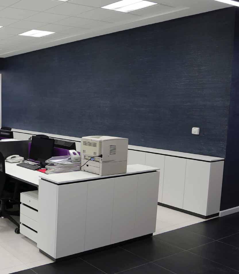
86 C86

87 CI-24 Passive Infrared HVAC/BAS Ceiling Sensor 360 coverage Interfaces directly with EMS or HVAC system through internal isolated relay Four-level Fresnel lens offers superior desktop detection Low profile design User adjustable time delay and sensitivity via DIP switch PROJECT LOCATION/TYPE Product Overview Description WattStopper s CI-24 ceiling mount passive infrared occupancy sensor reduces energy waste in unoccupied building spaces by communicating occupancy to EMS and HVAC systems. Operation The CI-24 occupancy sensor integrates with building control systems via an internal isolated relay. The isolated relay has normally open and normally closed outputs and is rated for 1 Amp at 24 VAC/ VDC. The CI-24 connects to 24 VAC or 24 VDC building control systems. Power pack use is not necessary. When occupancy is detected, the sensor signals a building control system that in turn either turns on devices, such as heating or air conditioning, or increases their levels. Likewise, when the controlled area is vacated, the building control system will reduce airflow and fan speed or turn devices off. Coverage Sensor coverage can reach up to 1200 square feet using the Extended Range lens and 500 square feet using the High Density lens (circular pattern) for walking motion. For typical desktop level activity, coverage can reach up to 300 square feet. Applications The CI-24 offers an easy way to reduce energy consumption in a large variety of building spaces. By working directly with a Building Automation System, the cost of purchasing power packs and the cost of labor for power pack installation is eliminated. Furthermore, the sensor s low unit cost and reduction in energy consumption result in fast paybacks. Features Detection Signature Analysis eliminates false triggers; provides immunity to RFI and EMI Digital time delay adjustment from 30 seconds to 30 minutes Two levels of sensitivity (minimum or maximum) are selectable through the DIP switch Multi-level Fresnel lens for superior desktop detection LED indicates occupancy detection Qualifies for ARRA-funded public works projects C87
88 O N Specifications Wiring, Mounting & Settings Dual-element, temperature compensated pyroelectric sensor Time delay adjustment from 30 seconds to 30 minutes Isolated relay with normally open and normally closed outputs; rated 1 24 VDC/VAC Operates at 24 VAC or 24 VDC +/- 10% Wiring Diagram 24VAC/VDC Supply* Cable Wires 1- Mounting options: ceiling tile or round mudring Dimensions: 3.3 diameter x 2.2 depth (85mm x 56mm), extends approximately 0.36 (9.1mm) from ceiling UL and cul listed Five year warranty EMS (or other building control system) Isolated Relay Contacts Normally Closed Contact Common Normally Open Contact 2-Grn 3-Orn 4-Yel O N DIP Switch Control for Time Delay, Sensitivity, and Override LED 24VAC/VDC Supply 24VAC/VDC Return Normally Closed Contact (closed when occupancy is not detected) Normally Open Contact (closed when occupancy is detected) 12VDC or 24VAC/VDC Return 5-Blk Common *CI-24 requires: 24VAC/VDC EMS VAV Mounting Ceiling 24VAC/VDC Supply Normally Closed Contact Coverage Coverage Patterns 8 ft Typical desk-top level Mud ring hole Ceiling attachment ring Rear housing Front housing 44 ft Extended Range Lens (Standard) CI-24 24VAC/VDC Return DIP Switch Settings DIP Switch # seconds 10 minutes 20 minutes 30 minutes 8 ft Typical desk-top level Blk 24 ft Common Normally Open Contact Sensitivity Minimum Maximum High Density Lens CI-24-1 Normal Override =ON =OFF =factory presets 22 ft 13 ft 7 ft 3 ft 0 3 ft 7 ft 13 ft 22 ft 12 ft 9 ft 7 ft 5 ft 3 ft 0 3 ft 5 ft 7 ft 9 ft 12 ft Coverage shown is maximum and represents coverage for half-step walking motion. Under ideal conditions, with no barriers or obstacles, coverage for half-step walking motion can reach up to 1200 ft 2 using the Extended Range lens and up to 500 ft 2 using the High Density lens. For typical desktop level of activity, coverage can reach up to 300 ft 2 using the High Density lens. Ordering Information Pub. No rev. 10/2013 Catalog No. Voltage Current Coverage CI VAC or 24 VDC CI-24-U 24 VAC or 24 VDC CI VAC or 24 VDC CI-24-1-U 24 VAC or 24 VDC Units are white -U = Product produced in the U.S. 37 ma 37 ma 37 ma 37 ma 360 ; up to 1200 ft 2 (111.5 m 2 ) 360 ; up to 1200 ft 2 (111.5 m 2 ) 360 ; up to 500 ft 2 (46.5 m 2 ) 360 ; up to 500 ft 2 (46.5 m 2 ) C88

89 CI-200 Series Passive Infrared Ceiling Sensors 360 coverage User-adjustable time delay and sensitivity Isolated relay for use with HVAC or other control systems ASIC enhances reliability and helps eliminate false triggers Low-profile design Built-in light level sensor Automatic or manual-on operation when used with a BZ-150 Power Pack PROJECT LOCATION/TYPE Product Overview Features Description WattStopper s CI-200 Series Passive Infrared (PIR) Ceiling Sensors provide 360 coverage to detect occupancy in the controlled area. These lowprofile sensors reliably control lighting in a variety of applications. Operation The CI-200 Series Sensors are 24 VDC and control lighting through WattStopper power packs. Utilizing the latest PIR technology, they turn lighting on when a difference is detected between the infrared energy from a human being in motion and the background space within the controlled area. After the area is vacated for a user-adjustable time delay, lighting automatically turns off. ASIC technology reduces components and enhances reliability Pulse Count Processing eliminates false off without reducing sensitivity Detection Signature Analysis eliminates false triggers and provides immunity to RFI and EMI Low-profile design ensures a clean and uncluttered ceiling appearance User-adjustable time delay from 15 seconds to 30 minutes by two-minute increments Coverage Coverage from the CI-200 Series Sensors can reach up to 1200 square feet using the Extended Range Lens, and 500 square feet using the High Density Lens (circular pattern) for walking motion. For typical desktop-level activity, coverage can reach up to 300 square feet. Applications Applications include open office spaces, computer rooms, conference rooms, classrooms and warehouses. Areas with high ceilings or with twolevel lighting can also be controlled. Due to low initial cost and the great energy saving potential, the sensors offer fast paybacks. Sensitivity is programmed through a DIP switch which has four settings ranging from minimum to maximum Light-level output can create bi-level lighting for added convenience and energy savings Isolated relay can be used to interface with HVAC, EMS or an additional lighting load LED indicates occupancy detection Qualifies for ARRA-funded public works projects C89
90 Specifications Wiring, Mounting & Settings Dual-element, temperature compensated pyroelectric sensor CI-200 contains isolated relay with N/O and N/C outputs; rated for 1 Amp at 24 VDC/VAC Adjustable digital time delay: 15 seconds to 30 minutes with ± 2% tolerance Integrated light level sensor: footcandles (43-2,045 lux) Wiring Diagram N Hot (Line) Power Pack / () Switch Mounting options: ceiling tile, round mud ring Max. CI-200s per power pack: B = 5, BZ = 7 Max. CI-205s per power pack: B = 10, BZ = 13 Dimensions: 3.3 x 2.2 (84mm x 56mm) diameter x depth; extends approximately.36 (9.1mm) from ceiling UL and cul listed Five year warranty Lighting DIP Switch for Time Delay and Sensitivity Blue Isolated Relay Outputs Closure upon Occupancy Normally Closed Contact Common Normally Open Contact Light Level Output 24VDC +24VDC Common Cable Wires 1-Brn 2-3-Orn Control Output 24VDC 4-Yel Control Return 5-Grn 6-Blu 7-Vio 8-Gra MAX MIN Coverage DIP Switch Settings DIP Switch # 15 seconds 2 minutes 4 minutes 6 minutes 8 minutes 10 minutes 12 minutes 14 minutes 16 minutes 18 minutes 20 minutes 22 minutes 24 minutes 26 minutes 28 minutes 30 minutes Coverage Patterns 8 ft Typical desk-top level DIP Switch # 7 8 Sensitivity Minimum Medium Low Medium High Maximum = ON = OFF = Factory Presets 44 ft Extended Range Lens (Standard) CI-200, CI-205 LED Mounting 8 ft Typical desk-top level Light Level Adjustment Ceiling Mud ring hole Ceiling attachment ring Rear housing Front housing 24 ft High Density Lens CI-200-1, CI ft 13 ft 7 ft 3 ft 0 3 ft 7 ft 13 ft 22 ft 12 ft 9 ft 7 ft 5 ft 3 ft 0 3 ft 5 ft 7 ft 9 ft 12 ft Ordering Information Pub. No rev. 5/2013 Catalog No. Voltage Current Coverage Features CI-200 CI-200-U CI CI-205 CI-205-U CI VDC 24 VDC 24 VDC 24 VDC 20 ma 20 ma 11 ma 11 ma 360 ; up to 1200 ft 2 (111.5 m 2 ) 360 ; up to 500 ft 2 (46.5 m 2 ) 360 ; up to 1200 ft 2 (111.5 m 2 ) 360 ; up to 500 ft 2 (46.5 m 2 ) MB-1 MB-2 Industrial Mounting Bracket Industrial Mounting Bracket for HID fixtures All units are white and use WattStopper power packs. Current consumption can be slightly higher when only one sensor per power pack is used. -U = ARRA compliant. Product produced in the U.S. Isolated relay, light level Isolated relay, light level C90

91 CI-300 Series Low Voltage PIR Ceiling Sensors Architecturally appealing low-profile appearance Plug terminal wiring for quick and easy installation Accepts low-voltage switch input for manual-on operation Automatic or manual-on operation when used with a BZ-150 Power Pack 360 coverage Walk-through mode increases savings potential PROJECT LOCATION/TYPE Product Overview Description WattStopper s CI-300 Passive Infrared (PIR) Ceiling Sensors automatically turn lighting on and off based on occupancy. The sensor mounts on the ceiling with a flat, low-profile appearance and provides 360 degrees of coverage. Operation CI-300 Series Sensors operate on 24 VDC, VAC or halfwave rectified. Utilizing the latest PIR technology, they automatically turn lighting on when a difference is detected between infrared energy from a human body in motion and the background space. When no occupancy is detected for the length of the time delay, lighting automatically turns off. For manual-on operation, the CI-300 will operate with a low-voltage momentary switch. Time Delay Options The CI-300 is factory set for a 20 minute time delay, ideal for both energy savings and user satisfaction in most applications. Installers can quickly select other fixed time delays (5, 10, 15 or 30 minutes) via DIP switches. Fixed time delays eliminate the occupant dissatisfaction associated with an automatically adjusted time delay option, and reduce callbacks. Walk-through mode may be enabled for added energy savings in spaces with frequent transient traffic. Applications CI-300 Series Sensors have the flexibility to work in a variety of applications that include open office spaces, computer rooms, conference rooms, classrooms and warehouses. Areas with high ceilings or with two-level lighting can also be controlled. The convenient mounting system keeps installation costs down to speed up the product s payback. Features Advanced control logic based on RISC microcontroller provides: - Detection Signature Processing to eliminate false triggers and provide immunity to RFI and EMI - Walk-through Mode turns lights off three minutes after the area is initially occupied ideal for brief visits such as mail delivery - Built-in light level sensor featuring simple, one-step setup LED indicates occupancy detection CI-300 Series Sensors work with low-voltage momentary switches for manual control DIP switch simplifies sensor adjustments Clip-mounting system simplifies ceiling tile installation Plug terminal wiring system for quick and easy installation Available with isolated relay for integration with BAS or HVAC Sensor coverage tested to NEMA Guide Publication WD C91
92 ON ECE Specifications 24 VDC/VAC Time delays: 5, 10, 15, 20, or 30 minutes, walkthrough, test mode Sensitivity adjustment: PIR (high/low) Multilevel Fresnel lens provides 360 coverage CI-300 contains isolated relay with N/O and N/C outputs; rated for 1 Amp at 30 VDC/VAC CI-300 built-in light level sensor: 10 to 300 footcandles (107.6 to 3,229.2 lux) Mounting options: ceiling tile; 4 square junction box with double-gang mud ring Max. CI-300s per power pack: B=5, BZ=7 Max. CI-305s per power pack: B=12, BZ=16 Dimensions: 4.5 x 1.02 (114.3mm x 25.9mm) diameter x depth UL and cul listed Five year warranty Wiring & Mounting Wiring Diagram (Line) () Ceiling Mounting N Hot Power Pack () Switch Lighting load Ceiling Blue Isolated Relay Outputs Common Normally Open Contact Normally Closed Contact Relay Common N.O. N.C. Depluggable terminal Optional Momentary Switch * Light Level (24VDC Out) Control (24VDC) Out Man. Switch +24V (In) Common Spring clips (2) Rear housing CI-300 Terminals * Connect * wire Connect only wire when only when momentary switch is momentary switch is installed Front cover Controls & Settings Coverage Product Controls Light level pushbutton DIP switches PIR lens Coverage Patterns 44 ft 13.4m Keyhole slots (for mounting to 4" octagonal box) Double gang mudring mounting holes PIR Activity LED () Extended Range Lens (Standard) CI-300, CI-305 DIP Switch Settings Switch# Time Delay Test Mode/20 min 30 seconds 5 minutes 10 minutes 15 minutes 20 minutes 25 minutes 30 minutes Walk-Through 4 Enabled Disabled PIR Sensitivity 5 Minimum Maximum 24 ft 7.3m Service Service Normal 6 On Mode 7 Manual On Auto On = Factory Setting = ON = OFF High Density Lens CI-300-1, CI ft 8 ft Typical desk-top level Typical desk-top level Ordering Information Pub. No rev. 5/ ft 13 ft 7 ft 3 ft 0 3 ft 7 ft 13 ft 22 ft 12 ft 9 ft 7 ft 5 ft 3 ft 0 3 ft 5 ft 7 ft 9 ft 12 ft Catalog No. Voltage Current Coverage Features CI-300 CI CI-305 CI VDC 24 VDC 24 VDC 24 VDC 20 ma 20 ma 9 ma 9 ma 360 ; up to 1200 ft 2 (111.5 m 2 ) 360 ; up to 500 ft 2 (46.5 m 2 ) 360 ; up to 1200 ft 2 (111.5 m 2 ) 360 ; up to 500 ft 2 (46.5 m 2 ) Isolated relay, light level Isolated relay, light level Sensors are white C92
 occupancy sensor")
93 CI-355 Passive Infrared Line Voltage Ceiling Sensor Architecturally appealing low profile appearance Terminal wiring for quick and easy installation Operates at 120, 230 (single phase), 277 or 347 VAC, 50/60 Hz 360 coverage Walk-through mode increases savings potential PROJECT LOCATION/TYPE Product Overview Features Description WattStopper s CI-355 passive infrared (PIR) occupancy sensor automatically turns lighting on and off based on occupancy. The sensor mounts on the ceiling with a flat, low-profile appearance and provides 360 degrees of coverage. Operation The CI-355 is line voltage and operates on a single phase at 120, 230, 277 or 347 VAC. The sensor uses passive infrared technology (PIR) to sense occupancy and automatically turn lighting on. PIR works by sensing the difference between infrared energy from a human body in motion and the background space. When no occupancy is detected for the length of the time delay, lighting automatically turns off. Advanced control logic based on RISC microcontroller provides: - Detection Signature Processing eliminates false triggers and provides immunity to RFI and EMI - Walk-through mode turns lights off 3 minutes after the area is initially occupied ideal for brief visits such as mail delivery - Built-in light level sensor featuring simple, one-step set-up Time Delay Options The CI-355 is factory set for a 20 minute time delay, ideal for both energy savings and user satisfaction in most applications. Installers can quickly select other fixed time delays (5, 10, 15 or 30 minutes) via DIP switches. Fixed time delays eliminate the occupant dissatisfaction associated with an automatically adjusted time delay option, and reduce callbacks. Walk-through mode may be enabled for added energy savings in spaces with frequent transient traffic. Applications The CI-355 works well in open office spaces, computer rooms, conference rooms, classrooms, and warehouses. It is a good choice for areas with high ceilings or with two-level lighting. The convenient mounting system keeps installation costs down. It also eliminates the need for a power pack by using line voltage wiring. Zero-crossing for long relay life LED indicates occupancy detection DIP switch simplifies sensor adjustments Clip mounting system makes ceiling tile installation simple Uses existing line voltage wiring and doesn t require a power pack Sensor coverage tested to NEMA Guide Publication WD C93
94 ON ECE Specifications 120/230 (single phase)/277/347 VAC, 50/60 Hz Time delays: 5, 10, 15, 20, or 30 minutes, walkthrough, test-mode Sensitivity adjustment: PIR (high/low) Multi-level, 360 Fresnel lens for superior occupancy detection Built-in light level sensor works from 10 to 300 footcandles (107.6 to 3,229.2 lux) Mounting options: 4 square junction box with double gang mudring; 4 inch octagonal j-box Dimensions: 4.5 diameter x 1.45 deep (114.3mm x 25.9mm) UL and cul listed Five year warranty Wiring & Mounting Wiring Diagram Ceiling Mounting 4" Square, 2.25" Deep* Junction Box with Double Gang Mudring attached Switch Hot Drop Ceiling Ground (Optional) CA-1 Adapter Rear Housing Sensor Flange Screws Controls & Settings Coverage Product Controls Light level pushbutton DIP switches PIR lens 8 ft Coverage Patterns Keyhole slots (for mounting to 4" octagonal box) 44 ft 13.4m Double gang mudring mounting holes PIR Activity LED (Green) Extended Range Lens (Standard) CI ft DIP Switch Settings Feature Switch# Time Delay Test Mode/20 min 30 seconds 5 minutes 10 minutes 15 minutes 20 minutes 25 minutes 30 minutes Front Cover Walk-Through 4 Enabled Disabled PIR Sensitivity 5 24 ft 7.3m Minimum Maximum Service Service Normal = Factory Setting = ON = OFF 6 High Density Lens CI Typical desk-top level Typical desk-top level Ordering Information Pub. No rev.5/ ft 13 ft 7 ft 3 ft 0 3 ft 7 ft 13 ft 22 ft CI-355 CI ft 9 ft 7 ft 5 ft 3 ft 0 3 ft 5 ft 7 ft 9 ft 12 ft Catalog No. Voltage Rating Coverage CA-1 Sensors are white. 120 VAC, 50/60 Hz 230 VAC (single phase), 50/60 Hz 277 VAC, 50/60 Hz 347 VAC, 50/60 Hz 120 VAC, 50/60 Hz 230 VAC (single phase), 50/60 Hz 277 VAC, 50/60 Hz 347 VAC, 50/60 Hz 0-800W Ballast/Tungsten/LED W Ballast/LED W Ballast/LED 0-800W Ballast/Tungsten/LED W Ballast/LED W Ballast/LED Cosmetic adapter for ceiling installations with 4 square j-box or Wiremold #V5752 box 360 ; up to 1200 ft 2 (111.5 m 2 ) 360 ; up to 500 ft 2 (46.5 m 2 ) C94
 circuitry automatically adjusts detection threshold Automatic or manual-on")
95 W Series Ultrasonic Ceiling Sensors Turns lights on and off based on occupancy to reduce energy costs Hallway and 500, 1000 and 2000 square foot coverage available Ideal for open office areas, conference rooms and restrooms Adjustable time delay from 15 seconds to 15 minutes Advanced Signal Processing (ASP) circuitry automatically adjusts detection threshold Automatic or manual-on operation when used with a BZ-150 Power Pack PROJECT LOCATION/TYPE Product Overview Description WattStopper s W Series Ultrasonic Ceiling Sensors are versatile motion detectors that control lighting in a wide variety of applications. W Series Sensors can be used individually or as part of an integrated system of WattStopper lighting control products. Operation The 24 VDC W Series Sensors utilize advanced omni-directional, ultrasonic technology to sense occupancy. When movement is detected in a controlled area, the W Series Sensors will switch lights on via low-voltage wiring through to a WattStopper power or auxiliary pack. Once the area is vacated and the user-adjustable time delay (15 seconds to 15 minutes) has elapsed, lighting systems automatically switch off. Manual-on Option To comply with code or for additional control options, W Series Sensors can be used with a BZ-150 power pack for manual-on/auto-off control. If this option is selected, occupants utilize a low-voltage momentary wall switch to turn on lights. Lights automatically turn off after the area is vacated and the user-adjustable time delay has elapsed. Applications Ultrasonic sensors effectively control offices, restrooms, utility areas, open office spaces and warehouses. The W-500A is perfect for offices, conference rooms, restrooms and other areas up to 500 square feet. The W-1000A fits in larger spaces, such as storage areas. The W-2000A is ideal for open office areas or large warehouses and can control partitioned open office spaces when configured in highly versatile zone patterns. The W-2000H reliably covers hallways with walls. Features ASP circuitry helps to eliminate false on Utilizes advanced omni-directional, ultrasonic technology for reliable occupancy detection Omni-directional transmission provides 360 of coverage Time delay adjustable from 15 seconds to 15 minutes 500, 1000, 2000-square foot and hallway coverage available to fit needs of specific applications Optional on override by installing the Override Pin provided with the sensor LED indicates occupancy detection Qualifies for ARRA-funded public works projects C95
96 Specifications Solid state, crystal-controlled (25 khz ± 0.005%) Temperature and humidity-resistant 25 khz receivers: W-500A contains one receiver, other models contain two receivers Adjustable time delay: 15 seconds to 15 minutes Wiring Standard Wiring Diagram Hot Power Pack Mounting options: ceiling tile, 4 sq. junction box Max. units per power pack: B = seven; BZ = nine Dimensions: 4.5 x 4.5 x 1.25 (115mm x 115mm x 32mm) W x L x D UL listed Five year warranty Multiple Sensor Wiring Diagram N Hot Power Pack (neutral) (line) (load) L O A D BLU Control Output Blue BLK Common RED +24VDC Switch Occupancy Sensor BLU Control Output Occupancy Sensor BLK Common RED +24VDC Coverage, Installation & Placement Coverage Pattern W-2000A 20' W-1000A 29' 12' W-500A 24' **W-2000H 10' Installation Occupancy Sensor 5' 45' 25' 20' 5' 5' 15' 20' 25' 45' Ordering Information Enclosed Office Sensor Placement W-500A W-500A-U W-1000A W-1000A-U W-2000A W-2000A-U W-2000H W-2000H-U 10' 12' 20' sensor Coverage shown represent half-step walking motion. Actual coverage can vary for each application depending on the shape and the use of space and the obstacles present. Coverage may be reduced if product is mounted greater than 12 feet high. The W-2000H drawing is not drawn to scale. Coverage is 10 x 90 in a hallway; enclosed spaces enhance coverage. Figure A Figure B For enclosed spaces, place sensors as in Figure A. Fixtures Fixtures Sensors placed Sensor as in Figure B may see out the 15' x 20' 15' x 20' door and cause Correct Incorrect false triggers. Sensor 24 VDC 24 VDC 24 VDC 24 VDC 30' x 30' Catalog No. Voltage Current Coverage 16 ma 16 ma 16 ma 16 ma All units are white and use WattStopper power packs. **Coverage for an enclosed hallway is 10 x 90 (see pattern above). -U = ARRA compliant. Product produced in the U.S. Time delay Sensitivity Bypass Open Office Sensor Placement 360 ; 500 ft 2 (46.5 m 2 ) 360 ; 1000 ft 2 (92.9 m 2 ) LED 360 ; 2000 ft 2 (185.8 m 2 ) 360 ; 90 linear ft (27.4 m)** Receiver Attach sensor to a vibration-free surface. Mount the sensors with the receivers facing the area of coverage. Note: Ultrasonic sensors should be placed 4 away from supply ducts, 6 from horizontal discharge ducts, and 6 from power packs. A typical layout for an open office space would be to place W-2000A sensors so they control zones that overlap. For partitioned spaces, a typical zone is about 25 x 25 with an overlap on the coverage that senses motion up to 30 x 30. Pub. No rev. 5/ C96

97 UT-300 Series Ultrasonic Low Voltage Ceiling Sensors Architecturally appealing low-profile appearance Accepts low-voltage switch input for manual-on operation Plug terminal wiring for quick and easy installation Walk-through mode increases savings potential Ultrasonic diffusers give more comprehensive coverage Automatic or manual-on operation when used with a BZ-150 Power Pack PROJECT LOCATION/TYPE Product Overview Features Description WattStopper s UT-300 Ultrasonic Ceiling Sensors automatically turn lighting on and off based on occupancy. The sensors mount on the ceiling with a flat, unobtrusive appearance and provides 360 coverage. Operation UT-300 Series Sensors operate on 24 VDC, VAC or halfwave rectified. They use 40 KHz high frequency ultrasound to sense occupancy and automatically turn lighting on. When no occupancy is detected for the length of the time delay, lighting automatically turns off. For manual-on operation, the units work with a lowvoltage momentary switch. Advanced control logic based on RISC microcontroller provides: - Advanced Signal Processing eliminates false triggers and provides immunity to RFI and EMI - Walk-through mode turns lights off three minutes after the area is initially occupied ideal for brief visits such as mail delivery LED indicates occupancy detection Coverage 500-2,000 square feet Available with isolated relay for integration with BAS or HVAC Time Delay Options The UT-300 is factory set for a 20 minute time delay, ideal for both energy savings and user satisfaction in most applications. Installers can quickly select other fixed time delays (5, 10, 15 or 30 minutes) via DIP switches. Fixed time delays eliminate the occupant dissatisfaction associated with an automatically adjusted time delay option, and reduce callbacks. Walk-through mode may be enabled for added energy savings in spaces with frequent transient traffic. Application UT-300 Series Sensors offer excellent control of lighting for many spaces, including restrooms, large offices, open office areas and hallways. They can control large partitioned office spaces when configured in zone patterns. Unit performance combined with ease of installation will provide fast payback and many years of energy savings. DIP switch simplifies sensor adjustments Patented ultrasonic diffusion technology spreads coverage to a wider area UT-300 Series Sensors work with low-voltage momentary switches for manual control Clip mounting system makes ceiling tile installation simple Uses plug terminal wiring system for quick and easy installation Qualifies for ARRA-funded public works projects Sensor coverage tested to NEMA Guide Publication WD C97
98 ON ECE Specifications Wiring & Mounting 24 VDC/VAC Time delays: 5, 10, 15, 20 or 30 minutes, Walkthrough/Test Modes Sensitivity adjustment: variable with trimpot Ultrasonic frequency: 40 khz UT-300 contains isolated relay with N/O and N/C outputs; rated for 1 Amp at 30 VDC/VAC Wiring Diagram (Line) () Mounting options: ceiling tile; 4 square junction box with double-gang mud ring Max. UT-300s per power pack: B=2, BZ=3 Max. UT-305s per power pack: B=3, BZ=4 Dimensions: 4.5 x 1 (114.3mm x 25.9mm) diameter x depth UL and cul listed Five year warranty Ceiling Mounting Ceiling N Hot Power Pack () Switch Lighting load Controls & Settings Coverage & Placement Ordering Information Pub. No rev. 5/2013 Blue Product Controls Ultrasonic transducer cones Ultrasonic activity LED (Green) Coverage Patterns 23' 16' 12' 5' 0' 5' 12' 16' 23' DIP switches Catalog No. Voltage Current Coverage Feature UT UT U UT UT U UT UT U UT UT UT OPTIONAL Momentary Switch* VDC 24 VDC 24 VDC 24 VDC 24 VDC 24 VDC Isolated Relay Outputs Common Normally Open Contact Normally Closed Contact * Connect * wire Connect only wire when only momentary switch is installed momentary switch is installed 45' 23' 16' 12' 0' UT-300/355-3 UT-300/305-3 UT-300/355-2 UT-300/305-2 UT-300/355-1 UT-300/305-1 Relay Common N.O. N.C. Control (24VDC) Out Man. Switch 40 ma 40 ma 45 ma +24V (In) 30 ma 30 ma 35 ma Common UT-300 Terminals Keyhole slots (for mounting to 4" octagonal box) Ultrasonic sensitivity trimpot 12' 16' 23' 45' UT-300/355-3 UT-300/305-3 HALLWAY APPLICATION Light level pushbutton Double gang mudring mounting holes Coverages shown represent halfstep walking motion when sensor is mounted 8-10 high. Actual coverage can vary for each application depending on the shape and use of space and the obstacles present. 500 ft 2 (46.5 m 2 ) 1000 ft 2 (92.9 m 2 ) 2000 ft 2 (185.8 m 2 ) 500 ft 2 (46.5 m 2 ) 1000 ft 2 (92.9 m 2 ) 2000 ft 2 (185.8 m 2 ) DIP Switch Settings Feature Switch# Time Delay Test Mode/20 min 30 seconds 5 minutes 10 minutes 15 minutes 20 minutes 25 minutes 30 minutes Placement All units are white and use WattStopper power packs. Current consumption can be slightly higher when only one sensor per power pack is used. -U = ARRA compliant. Product produced in the U.S. 30' x 30' Depluggable terminal Spring clips (2) Rear housing Front cover Walk-Through 4 Enabled Disabled = ON = OFF Typical layout for open office space would be to place UT sensors so they control zones that overlap. For partitioned spaces, a typical zone is about 25 x 25 with an overlap on the coverage up to 30 x 30. Isolated relay Isolated relay Isolated relay Service 5 Service Normal = Factory Setting C98

99 WT Ultrasonic Ceiling Sensors Ultrasonic technology with 32 KHz frequency Automatic or manual-on operation when used with a BZ-150 Power Pack User-adjustable DIP switch time delay and sensitivity settings Hallway and 600, 1100 and 2200 square foot coverages available Advanced Signal Processing circuitry automatically adjusts detection threshold Isolated relay allows sensor to interface with building control systems PROJECT LOCATION/TYPE Product Overview Description WattStopper s WT Ultrasonic Ceiling Sensors utilize 32 KHz frequency ultrasonic technology to detect occupancy. The sensors are available in several models to control lighting in a wide variety of applications. Operation WT Sensors are 24 VDC and utilize advanced, omni-directional, ultrasonic technology. When movement is detected in a controlled area, it switches lighting on through a WattStopper power or auxiliary pack. The sensor controls the power pack through low voltage wiring. Once the area is vacated and the time delay has elapsed, lighting systems automatically switch off. Advanced Signal Processing (ASP) WT Sensors use WattStopper s ASP circuitry, which filters out moving air noise by checking for small cyclical changes found in turbulent air. This helps to eliminate false on problems found in sensors without ASP. Applications WT sensors offer excellent control of lighting for many areas of a building. The sensors are designed to effectively control offices, restrooms, storage areas and open office areas, and can control large partitioned office spaces when configured in zone patterns. The WT can be used with BD Din Rail Mounted Power Packs and low-voltage momentary wall switches to achieve manual-on/auto-off control. The WT sensors superior performance and ease of installation will provide fast paybacks and many years of energy savings. Features ASP circuitry helps to eliminate false on Advanced, omni-directional, ultrasonic technology for reliable occupancy detection Angled transmitter and receiver pairs help optimize sensitivity while eliminating unwanted detection from ceiling air movement Coverage ranges from 600 to 2200 square feet, and 90 linear feet for hallways Isolated relay can interface with HVAC, EMS or an additional lighting load DIP switch-adjustable time delay and sensitivity LED indicates occupancy detection Qualifies for ARRA-funded public works projects C99
100 S Specifications Solid state, crystal-controlled ( khz ± 0.002%) Omni-directional transmission (360 coverage) Temperature and humidity resistant 32 khz receivers Digital DIP switch time delay: 15 seconds to 30 minutes Isolated relay with N/O and N/C outputs; rated for 1 30 VDC/VAC Mounts to ceiling tile or Wiremold V5738-WH box Max. WT-605s per power pack: B=4, BZ=5 Max. WT-600s per power pack: B= 3, BZ=4 Max. WT-1105s, WT-2205s, WT-2255s: B=3, BZ=5 Max. WT-1100s, WT-2200s, WT-2250s: B=2, BZ=3 Dimensions: 4.8 x 1.5 (122mm x 38mm) diameter x depth UL and cul listed Five year warranty Wiring, Installation & Placement Wiring & Controls () (Line) N Power Pack Hot () Switch Lighting Transducers Installation Blue Isolated Relay Outputs Cable Closure upon Occupancy Wires Normally Closed Contact 1 Brn Common 2 Normally Open Contact 3 Orn Control Output 24VDC 4 Yel Control Return 5 Grn No Connection 6 Blu +24VDC 7 Vio Common 8 Gra ON DIP switch LED Sensitivity Mount the sensors to a vibration-free surface with the receivers facing the area of coverage. Note: Place 4 away from supply ducts, 6 from horizontal discharge ducts and 6 from power packs. Enclosed Office Placement Open Office Placement Coverage & Settings Coverage Pattern 21' 14' 5' 0' 5' 14' 21' Figure A Fixtures Correct Fixtures 15' x 20' 15' x 20' Incorrect For enclosed spaces, place sensors as in Figure A. Sensors placed as in Figure B may see out the door and cause false triggers. 45' 26' 22' 0' 22' 26' 45' WT-1100/1105 Figure B WT-2200/2205 WT-600/605 WT-2250/2255 Coverages shown represent half-step walking motion. Actual coverages can vary for each application depending on the shape and use of space and the obstacles present. Coverage may be reduced if product is mounted greater than 12 feet high. 30' x 30' DIP Switch Settings = factory preset =ON =OFF DIP Switch # Time Delay seconds 2 minutes 4 minutes 6 minutes 8 minutes 10 minutes 12 minutes 14 minutes A typical layout for an open office space would be to place WT-2200 or WT-2205 sensors so they control zones that overlap. For partitioned spaces, a typical zone is about 25 x 25 with an overlap on the coverages that senses motion up to 30 x minutes *16 minutes 18 minutes 20 minutes 22 minutes 24 minutes 26 minutes 28 minutes 30 minutes Output Disable Override Ordering Information Pub. No rev. 10/2010 Catalog No. Voltage Current Coverage Feature WT-605 WT-600 WT-1105 WT-1100 WT-2205 WT-2200 WT-2255 WT VDC 24 VDC 24 VDC 24 VDC 24 VDC 24 VDC 24 VDC 24 VDC 27 ma 37 ma 30 ma 40 ma 30 ma 40 ma 30 ma 40 ma 180 one-sided, 600 ft 2 (55.7 m 2 ) 180 one-sided, 600 ft 2 (55.7 m 2 ) 360 two-sided, 1100 ft 2 (102.2 m 2 ) 360 two-sided, 1100 ft 2 (102.2 m 2 ) 360 two-sided, 2200 ft 2 (204.4 m 2 ) 360 two-sided, 2200 ft 2 (204.4 m 2 ) 360 two-sided, 90 linear ft (27.4 m) 360 two-sided, 90 linear ft (27.4 m) Isolated relay Isolated relay Isolated relay Isolated relay All units are white and use WattStopper power packs. Current consumption can be slightly higher when only one sensor per power pack is used C100

101 UT-355 Ultrasonic Line Voltage Ceiling Sensor Utilizes advanced, omni-directional, ultrasonic technology Architecturally appealing low-profile appearance Operates at 120, 230 (single phase), 277 or 347 VAC, 50/60 Hz Terminal wiring for quick and easy installation Ultrasonic diffusers provide more comprehensive coverage PROJECT LOCATION/TYPE Walk-through mode increases savings potential Product Overview Description WattStopper s low-profile UT-355 Ultrasonic Line Voltage Ceiling Sensor automatically turns lighting on and off based on occupancy. The sensor mounts on the ceiling with a flat, unobtrusive appearance and provides 360 coverage. Operation The UT-355 is line voltage and operates on a single phase at 120, 230, 277, or 347 VAC. It uses high frequency (40 KHz) ultrasound to sense occupancy and automatically turn lighting on. When no occupancy is detected for the length of the time delay, lighting automatically turns off. Time Delay Options The UT-355 is factory set for a 20 minute time delay, ideal for both energy savings and user satisfaction in most applications. Installers can quickly select other fixed time delays (5, 10, 15 or 30 minutes) via DIP switches. Fixed time delays eliminate the occupant dissatisfaction associated with an automatically adjusted time delay option, and reduce callbacks. Walk-through mode may be enabled for added energy savings in spaces with frequent transient traffic. Application UT sensors offer excellent control of lighting for many spaces, including restrooms and large offices. The UT sensors performance and ease of installation will provide fast paybacks and many years of energy savings. Features Advanced control logic based on RISC microcontroller provides: - Advanced Signal Processing to eliminate false triggers and provide immunity to RFI and EMI - Walk-through Mode to turn lights off three minutes after the area is initially occupied, ideal for brief visits such as mail delivery Zero-crossing for long relay life LED indicates occupancy detection Coverage 500-2,000 square feet DIP switch simplifies sensor adjustments Patented ultrasonic diffusion technology spreads coverage to a wider area Clip mounting system makes ceiling tile installation simple Terminal wiring system provides quick and easy installation Sensor coverage tested to NEMA Guide Publication WD Qualifies for ARRA-funded public works projects C101
102 ON ECE Specifications Wiring & Mounting 120/230 (single phase)/277/347 VAC, 50/60 Hz Time delays: 5, 10, 15, 20, or 30 minutes, Walkthrough & Test modes Sensitivity adjustment: variable with trimpot Ultrasonic frequency of 40 khz Wiring Diagram Mounting options: 4 square junction box with double-gang mud ring; 4 octagonal junction box Dimensions: 4.5 x 1.45 (114.3mm x 25.9mm) diameter x depth UL and cul listed Five year warranty Ceiling Mounting 4" Square, 2.25" Deep* Junction Box with Double Gang Mudring attached Switch Hot Drop Ceiling CA-1 Adapter Ground (Optional) Rear Housing Sensor Flange Screws Front Cover Controls & Settings Coverage & Placement Ordering Information Product Controls Ultrasonic transducer cones Ultrasonic activity LED (Green) DIP switches Coverage Patterns 45' 23' 16' 12' 23' 16' 12' 5' 0' 5' 12' 16' 23' Catalog No. Voltage/Description Rating Coverage UT UT U UT UT U UT UT U CA VAC, 50/60 Hz; 230 VAC (single phase)50/60 Hz; 277 VAC, 50/60 Hz; or 347 VAC, 50/600 Hz Cosmetic adapter for ceiling installations with 4 square j-box or Wiremold #V5752 box Sensors are white. -U = ARRA compliant. Product produced in the U.S. 0' UT UT-300/305-3 UT UT-300/305-2 UT UT-300/ Maximum Mounting Height Keyhole slots (for mounting to 4" octagonal box) Ultrasonic sensitivity trimpot Light level pushbutton 12' 16' 23' 45' UT UT-300/305-3 HALLWAY APPLICATION Double gang mudring mounting holes Coverages shown represent half-step walking motion when sensor is mounted 8-10 high. Actual coverage can vary for each application depending on the shape and use of space and the obstacles present. DIP Switch Settings Feature Switch# Time Delay Test Mode/20 min 30 seconds 5 minutes 10 minutes 15 minutes 20 minutes 25 minutes 30 minutes Placement W Ballast/Tungsten/ LED W Ballast/LED, or W Ballast/LED 30' x 30' Typical layout for open office space would be to place UT sensors so they control zones that overlap. For partitioned spaces, a typical zone is about 25 x 25 with an overlap on the coverage up to 30 x ft 2 (45.5 m 2 ) 1000 ft 2 (92.9 m 2 ) 2000 ft 2 (185.8 m 2 ) Walk-Through 4 Enabled Disabled = ON = OFF Service 5 Service Normal = Factory Setting Pub. No rev. 5/ C102

103 DT-300 Series Low Voltage Dual Technology Ceiling Sensors Architecturally appealing low-profile appearance Walk-through mode increases savings potential Plug terminal wiring for quick and easy installation Accepts low-voltage switch input for manual-on operation Ultrasonic diffusers give more comprehensive coverage Supports automatic or manual-on operation PROJECT LOCATION/TYPE Product Overview Description The DT-300 Series Dual Technology Ceiling Sensors combine the benefits of passive infrared (PIR) and ultrasonic technologies to detect occupancy. Sensors have a flat, unobtrusive appearance and provide 360 degrees of coverage. Operation Low voltage DT-300 Series sensors utilize a WattStopper power pack to turn lights on when both PIR and ultrasonic technologies detect occupancy. They can also work with a low voltage switch for manual-on operation. PIR technology senses motion via a change in infrared energy within the controlled area, whereas ultrasonic uses 40KHz high frequency ultrasound. Once lights are on, detection by either technology holds them on. When no occupancy is detected for the length of the time delay, lights turns off. DT-300 Series Sensors can also be set to trigger lights on when either technology or both detect occupancy, or to require both technologies to hold lighting on. Time Delay Options The DT-300 is factory set for a 20 minute time delay, ideal for both energy savings and user satisfaction in most applications. Installers can quickly select other fixed time delays (5, 10, 15 or 30 minutes) via DIP switches. Fixed time delays eliminate the occupant dissatisfaction associated with an automatically adjusted time delay option, and reduce callbacks. Walk-through mode may be enabled for added energy savings in spaces with frequent transient traffic. Application DT-300 Series Dual Technology Sensors have the flexibility to work in a variety of applications, where one technology alone could cause false triggers. Ideal applications include classrooms, open office spaces, large offices and computer rooms. The DT-300 Series mounting system makes them easy to install in ceiling tiles or to junction boxes, providing the flexibility to be used in a wide range of spaces. C103 Features Advanced control logic based on RISC microcontroller provides: - Detection Signature Processing eliminates false triggers and provides immunity to RFI and EMI - Walk-through mode turns lights off three minutes after the area is initially occupied ideal for brief visits such as mail delivery - Available with built-in light level sensor featuring simple, one-step setup Sensors work with low-voltage momentary switches to provide manual control Patented ultrasonic diffusion technology spreads coverage to a wider area LEDs indicate occupancy detection Uses plug terminal wiring system for quick and easy installation Eight occupancy logic options provide the ability to customize control to meet application needs Available with isolated relay for integration with BAS or HVAC Qualifies for ARRA-funded public works projects Sensor coverage tested to NEMA Guide Publication WD
104 ON ECE Specifications 24 VDC/VAC Ultrasonic frequency: 40kHz Time delays: 5, 10, 15, 20, or 30 minutes, Walkthrough/Test Modes Sensitivity adjustment: High/low (PIR); variable with trim pot (ultrasonic) Built-in light level sensor: 10 to 300 footcandles (107.6 to 3,229.2 lux) Low-voltage, momentary switch input for manual on or off operation DT-300 contains an isolated relay with N/O and N/C outputs; rated for 1 30 VDC/VAC Multi-level Fresnel lens provides 360 coverage Mounting options: ceiling tile; 4 octagonal J-box, 1.5 deep Max DT-300s per power pack: B=2, BZ=3 Max DT-305s per power pack: B=3, BZ=4 Dimensions: 4.50 diameter x 1.02 deep (114.3mm x 25.9mm) UL and cul listed Five year warranty Wiring & Mounting Wiring Diagram () Ceiling Mounting (Line) N Hot Power Pack () Switch Lighting load Ceiling Blue Isolated Relay Outputs Common Normally Open Contact Normally Closed Contact Momentary Switch Relay Common N.O. N.C. Control (24VDC) Out Man. Switch +24V (In) Common Depluggable terminal Spring clips (2) Rear housing Front cover *Momentary switch connection is optional. Connect only when momentary switch is installed. DT-300 Terminals Controls & Settings Coverage Product Controls Ultrasonic sensitivity trimpot DIP switches Ultrasonic transducer cones Ultrasonic activity LED (Green) Light level pushbutton Coverage Pattern Keyhole slots (for mounting to 4" octagonal box) Double gang mudring mounting holes 36 ft (10.97m) PIR Activity LED () PIR lens DIP Switch Settings Feature Switch# Time Delay Test Mode/20 min 30 seconds 5 minutes 10 minutes 15 minutes 20 minutes 25 minutes 30 minutes Walk-Through Enabled Disabled 4 PIR Sensitivity 5 Minimum Maximum Occupancy Logic Initial Occupancy Maintain Occupancy Re-trigger (seconds duration) The control technology (occupancy logic) is selectable. The default setting requires both technologies to trigger on, either to hold on, and is recommended for most applications. Occupancy Logic Settings Standard Option 1 Option 2 Option 3 Option 4 Option 5 Option 6 Option 7 Trigger Standard Both Either Either(5) Option 1 Either Either Either(5) Option 2 PIR Either Either(5) Option 3 Both PIR Both(5) Option 4 PIR PIR PIR(5) Option 5 Either PIR Either(5) Option 6 Man. Either Either(30) Option 7 Man. PIR Both(30) = Factory Setting = ON = OFF 36 ft x 36 ft (10.97m x 10.97m) Coverage shown is maximum and represents half-step walking motion. Under ideal conditions, coverage for half-step walking motion can reach up to 1000 ft 2. Ordering Information Pub. No rev. 5/2013 Catalog No. Voltage Current Coverage Features DT-300 DT-300-U DT-305 DT-305-U 24 VDC/VAC 24 VDC/VAC 43 ma 35 ma up to 1000 ft 2 (92.9 m 2 ) up to 1000 ft 2 (92.9 m 2 ) Sensors are white and use WattStopper power packs. Current consumption can be slightly higher when only one sensor per power pack is used. -U = ARRA compliant. Product produced in the U.S. Isolated relay, light level C104

105 DT-355 Dual Technology Line Voltage Ceiling Sensor Architecturally appealing low profile appearance Operates at 120, 230 (single phase), 277 or 347 VAC, 50/60 Hz Terminal wiring for quick and easy installation Ultrasonic diffusers give more comprehensive coverage Walk-through mode increases savings potential PROJECT LOCATION/TYPE Product Overview Description WattStopper s low profile DT-355 dual technology occupancy sensor combines the benefits of passive infrared (PIR) and ultrasonic technologies. The sensor mounts on the ceiling with a flat, unobtrusive appearance and provides 360 degrees of coverage. Operation The DT-355 is line voltage and operates on a single phase at 120, 230, 277 or 347 VAC. The sensor turns lighting on when both PIR and ultrasonic technologies detect occupancy. PIR technology senses the difference between infrared energy from a human body in motion and the background space. Ultrasonic technology uses high frequency (40KHz) ultrasound to sense motion within the space. Once lighting is on, detection by either technology holds lighting on. When no occupancy is detected for the length of the time delay, lighting turns off. The DT-355 can also be set so that only one technology is needed to trigger or both technologies are needed to hold lighting on. Time Delay Options The DT-355 is factory set for a 20 minute time delay, ideal for both energy savings and user satisfaction in most applications. Installers can quickly select other fixed time delays (5, 10, 15 or 30 minutes) via DIP switches. Fixed time delays eliminate the occupant dissatisfaction associated with an automatically adjusted time delay option, and reduce callbacks. Walk-through mode may be enabled for added energy savings in spaces with frequent transient traffic. Application WattStopper s patented dual technology has the flexibility to work in a variety of applications, where one technology alone could encounter false triggers. Ideal applications include classrooms, open office spaces, large offices, and computer rooms. In addition, because the DT-355 can be mounted onto a variety of junction boxes, the sensor has the flexibility to be used in a wide range of spaces. The sensors eliminate the need for a power pack by using line voltage wiring. C105 Features Advanced control logic based on RISC microcontroller provides: - Detection Signature Processing eliminates false triggers and provides immunity to RFI and EMI - Walk-through mode turns lights off 3 minutes after the area is initially occupied ideal for brief visits such as mail delivery - Built-in light level sensor featuring simple, one-step setup Zero-crossing for long relay life Ultrasonic diffusion technology spreads coverage to a wider area (patent pending) DIP switch simplifies sensor adjustments LEDs indicate occupancy detection Uses existing line voltage wiring and doesn t require a power pack Six occupancy logic options give users the ability to customize control to meet application needs Qualifies for ARRA-funded public works projects Sensor coverage tested to NEMA Guide Publication WD
106 ON ECE Specifications 120/230 (single phase)/277/347 VAC, 50/60 Hz Ultrasonic frequency of 40kHz Time delays: 5, 10, 15, 20, or 30 minutes, walkthrough, test-mode Sensitivity adjustment: High/low (for PIR sensitivity); ultrasonic sensitivity is variable with trimpot Built-in light level sensor works from 10 to 300 footcandles (107.6 to 3,229.2 lux) Multi-level, 360 Fresnel lens for superior occupancy detection Mounting options: 4 square junction box with double gang mudring; 4 inch octagonal junction box Dimensions: 4.50 diameter x 1.45 deep (114.3mm x 25.9mm) UL and cul listed Five year warranty Wiring & Mounting DT-355 Wiring Diagram Ceiling Mounting 4" Square, 2.25" Deep* Junction Box with Double Gang Mudring attached Drop Ceiling Hot CA-1 Adapter Ground (Optional) Rear Housing Sensor Flange Screws Controls & Settings Coverage Product Controls Ultrasonic sensitivity trimpot DIP switches Ultrasonic transducer cones Ultrasonic activity LED (Green) Light level pushbutton Coverage Pattern Keyhole slots (for mounting to 4" octagonal box) Double gang mudring mounting holes PIR Activity LED () PIR lens 36 ft (10.97m) DIP Switch Settings Feature Switch# Time Delay Test Mode/20 min 30 seconds 5 minutes 10 minutes 15 minutes 20 minutes 25 minutes 30 minutes Walk-Through Enabled Disabled 4 PIR Sensitivity 5 Minimum Maximum Front Cover Occupancy Logic Initial Occupancy Maintain Occupancy Re-trigger (seconds duration) Trigger Standard Both Either Either(5) Option 1 Either Either Either(5) Option 2 PIR Either Either(5) Option 3 Both PIR Both(5) Option 4 PIR PIR PIR(5) Option 5 Either PIR Either(5) Option 6 Man. Either Either(30) Option 7 Man. PIR Both(30) = Factory Setting = ON = OFF The control technology (occupancy logic) is selectable. The default setting requires both technologies to trigger on, either to hold on, and is recommended for most applications. Occupancy Logic Settings Standard Option 1 Option 2 Option 3 Option 4 Option 5 Option 6 Option 7 36 ft x 36 ft (10.97m x 10.97m) Coverage shown is maximum and represents half-step walking motion. Under ideal conditions, coverage for half-step walking motion can reach up to 1000 ft 2 (92.9 m 2 ). Ordering Information Catalog No. Voltage Rating Coverage DT-355 DT-355-U 120 VAC, 50/60 Hz 277 VAC, 50/60 Hz 347 VAC, 50/60 Hz 0-800W Ballast/Tungsten/LED W Ballast/LED W Ballast/LED up to 1000 ft 2, (92.9 m 2 ) CA-1 Cosmetic adapter for ceiling installations with 4 square j-box or Wiremold #V box Sensors are white. -U = ARRA compliant. Product produced in the U.S. Pub. No rev. 5/ C106

107 WPIR Passive Infrared Ceiling Sensor PIR sensor turns lights on and off based on occupancy User-adjustable time delay of 30 seconds to 30 minutes ASIC technology reduces components and provides greater reliability 30-segment, multi-element Fresnel lens Automatic or manual-on operation when used with a BZ-150 Power Pack PROJECT LOCATION/TYPE Product Overview Description WattStopper s WPIR Sensor is a versatile ceilingmount sensor that utilizes the latest passive infrared (PIR) technology to turn lights on and off based on occupancy. The WPIR controls lighting in a wide variety of applications, but is especially adept at controlling small spaces with well-defined coverage. Operation The WPIR Ceiling Sensor utilizes the latest PIR technology to detect the difference between the infrared energy from a person in motion and the background space within the controlled area. When occupancy is detected, this 24 VDC sensor turns lighting or HVAC systems on through a WattStopper power pack controlled through low voltage wiring. When occupants leave the area, lighting is switched off after the user-adjustable time delay has elapsed. Fresnel Lens and Coverage The WPIR is equipped with a multi-element Fresnel lens that allows the sensor to efficiently collect infrared energy and provides optical gain over a defined field of view. The profile of each groove facet is determined by computer simulation to produce the sharpest images possible from a distant object. The use of a 30-segment lens allows overlapping coverage within the defined field of view. The coverage is partially determined by the view available to the sensor. Mounted to a wall, the WPIR will produce a completely different viewing pattern. Zone 4 and 5 (see diagram on back) are then capable of sensing up to 45 feet. Applications The WPIR can effectively cover small offices, utility areas or computer rooms. Additional applications include racquetball courts, garage areas, library aisleways and storage rooms. Features ASIC technology enhances reliability and provides immunity to RFI and EMI Uses the latest PIR technology to reliably control lighting in a variety of applications User-adjustable time delay of 30 seconds to 30 minutes Incorporated daylight filter prevents shortwavelength infrared waves, such as those emitted by the sun, from affecting WPIR Multi-element Fresnel lens allows the sensor to efficiently collect infrared energy and provide optical gain over a defined field of view Alternate viewing patterns depending on mounting choice Optional on override through logic key/on bypass LED indicates occupancy detection C107
108 Specifications Dual-element, temperature compensated pyroelectric sensor Adjustable time delay: 30 seconds to 30 minutes Poly IR4 lens, optical filter material Control output: 100mA maximum Max. units per power pack: B = 8; BZ = 10 Dimensions: 2.5 x 2.5 x 1.14 (64mm x 64mm x 29mm) W x L x D UL and cul listed Five year warranty Wiring & Controls Product Controls LED Indicator Time Delay Adjustment SENSE TIME Sensitivity Adjustment Override Mounting Holes Sensor Window Factory preset 30-minute time delay for maximum sensitivity Wiring Diagram Hot Power Pack Blue Switch WPIR Sensor Coverage & Placement Coverage Pattern Horizontal Pattern for Ceiling Mount Typical Office Placement 15' Ceiling Height 8' 10' 12' 15' 20' 25' *8' Zone Zone 1 Zone 2 Zone 3 Zone 4 Zone 5 Detection Zones Zone 4 Zone 3 Zone Vertical Pattern for Ceiling Mount Zone * Wall mounted Horizontally 15' Sensor For an enclosed office, the WPIR should be placed in the corner of the room so that it will detect occupants as they enter the room. For the aisleway between bookstacks, the WPIR should be placed at the end of each bookstack to detect occupancy upon entrance to the aisle way from either direction. For longer bookstacks, two or more WPIRs can be used. Aisleway Library Bookstack Placement WPIR Sensor Bookstack Fixture Ordering Information Pub. No rev. 10/2009 Catalog No. Voltage Current Coverage WPIR 24 VDC 14 ma 300 ft 2 (27.9 m 2 ) All units are white and use WattStopper power packs C108

109 CX-100 Series Passive Infrared Ceiling/Wall Sensors Turns lights on and off based on occupancy User-adjustable time delay and sensitivity ASIC technology reduces components and provides greater reliability Choice of four coverage patterns Built-in light level sensor Isolated relay for use with HVAC or other control systems Automatic or manual-on operation when used with a BZ-150 Power Pack PROJECT LOCATION/TYPE Product Overview Features Description WattStopper s CX-100 Series Passive Infrared (PIR) Ceiling/Wall Sensors detect occupancy to control lighting in a wide variety of applications. These sensors provide superior coverage and performance with great energy savings. Operation CX-100 Series Sensors are 24 VDC and control lighting systems through WattStopper power packs. Utilizing the latest PIR technology, they turn lights on when a difference is detected between infrared energy from a human body in motion and the background space. After the area is vacated and the time delay elapses, lighting automatically turns off. ASIC technology reduces components and enhances reliability Pulse Count Processing eliminates false off without reducing sensitivity Detection Signature Analysis eliminates false triggers and provides immunity to RFI and EMI Digital time delay adjustable from 15 seconds to 30 minutes Adjustable sensitivity enables occupancy detection to match the level of activity for each space LED indicates occupancy detection Coverage Choices The CX-100 Series Sensors are available with a choice of coverage patterns. The standard lens offers coverage up to 1000 square feet for typical desktop activity. When using the CX-100/105-1 or -3 lens, motion moving toward sensors will begin to be detected at 55 to 60 feet. Applications The CX sensors are ideal for large areas and can cover up to 2000 square feet of walking motion. By choosing the proper lens pattern for each application, the sensors can reliably cover large offices, computer rooms, classrooms, aisleways, warehouses and open offices where coverage cut-off is desired. Corner mounting to a wall or ceiling adds versatility and more control to the coverage. The CX-100 s integrated light level sensor can create bi-level control for added energy savings Multilevel Fresnel lens for superior desktop occupancy detection with four lens patterns Isolated relay can interface with HVAC, EMS and monitoring systems, or with an additional lighting load Dual-element, temperature compensated pyroelectric sensor Swivel mounting bracket for convenient corner mounting to wall or ceiling Qualifies for ARRA-funded public works projects C109
110 Specifications Wiring & Settings Coverage & Mounting Dual-element, temperature compensated pyroelectric sensor CX-100 contains isolated relay with N/O and N/C outputs; rated for 1 Amp at 24 VDC/VAC Adjustable time delay: 15 seconds to 30 minutes CX-100 integrated light level sensor: three to 200 footcandles (32 to 2,152 lux) Wiring Diagram Coverage Patterns Top N Hot 50ft. (Line) Power Pack Blue () () Isolated Relay Outputs Wires Normally Closed Contact BRN Common RED Normally Open Contact ORN Control Output 24VDC YEL Common GRN Light Level Output 24VDC BLU +24VDC VIO Common GRA CX-100 Dense wide angle standard 55ft. 16ft 8ft 0 8ft 16ft Switch on Lighting Time Delay DIP CX Long range Max.CX-100s per power pack: B=6, BZ=8 Max. CX-105s per power pack: B=14, BZ=18 Dimensions: 3.3 x 3.3 x 2.1 (83.8mm x 83.8mm x 53.3mm) W x L x D UL and cul listed Five year warranty Light Level Sensitivity DIP Switch Settings DIP Switch # Time Delays seconds 2 minutes 4 minutes 6 minutes 8 minutes 10 minutes 12 minutes 14 minutes 16 minutes 18 minutes 20 minutes 22 minutes 24 minutes 26 minutes 28 minutes 30 minutes Override =on =off =factory preset Mounting Ceiling A swivel mounting bracket allows the sensor to be angled for wall or ceiling mounting. Ordering Information Pub. No rev. 5/ ft Side 5ft 0 30ft 15ft ft 7ft 15ft 25ft 55ft CX Two-sided aisleway 33.5ft 38ft 21ft 10ft CX-100 CX CX CX CX-105 CX-105-U CX CX U CX CX MB-1 MB ft 21ft 33.5ft 38ft 24 VDC 24 VDC 24 VDC 24 VDC 24 VDC 24 VDC 67ft 15ft 0 10ft 0 3 ft 0 30ft 15ft ft 55ft 85 90ft CX One-sided aisleway 10 ft 0 10 ft 20 ft 30 ft 40 ft 50 ft Industrial Mounting Catalog No. Voltage Current Coverage Features 19 ma 19 ma 19 ma 19 ma 8 ma 8 ma 33 using MB-1 with maximum rotation up to 2000 ft 2 (185.8 m 2 ) up to 90 linear ft (27.4 m) up to 120 linear ft (36.6 m) up to 50 linear ft (15.2 m) up to 2000 ft 2 (185.8 m 2 ) up to 90 linear ft (27.4 m) 24 VDC 24 VDC 8 ma 8 ma up to 120 linear ft (36.6 m) up to 50 linear ft (15.2 m) Industrial Mounting Bracket (recommended for use with -3 and -4 lenses) Industrial Mounting Bracket for HID fixtures All units are white and use WattStopper power packs. Current consumption can be slightly higher when only one sensor per power pack is used. -U = ARRA compliant. Product produced in the U.S. Grooves on the bracket help to achieve desired angle for coverage. MB-1 Industrial Mounting Bracket The MB-1 is used for ceiling or fixture installations in industrial settings. Coverages shown are maximum and represent half-step walking motion. Under ideal conditions with no barriers or obstacles, coverage for half-step walking motion with the standard lens can reach up to 2000 ft 2, while coverage for typical desktop activity can reach up to 1000 ft 2. When using the CX-100/105-1 or -3 lens, motion moving toward sensors will begin to be detected at 55 to 60 feet. isolated relay, light level isolated relay, light level isolated relay, light level isolated relay, light level C110

111 CB Low Temperature Passive Infrared Occupancy Sensor PIR occupancy sensor for areas of extreme low temperature Watertight enclosure prevents moisture and dust from affecting detection Choice of three coverage patterns Convenient DIP switch adjustments of time delay and sensitivity Ideal for cold storage rooms, freezers and outdoor locations Isolated relay contact for use with HVAC or other control systems PROJECT LOCATION/TYPE Product Overview Description The CB-100 passive infrared (PIR) occupancy sensor was engineered for installation in cold and damp conditions including the outdoors. It uses electronic components to allow for reliable operation in extreme temperature and environmental conditions. Operation The CB-100 operates on 24 VDC and controls lighting through WattStopper power packs. It is equipped with a swivel mount bracket for convenient installation. The unit detects occupancy and turns lighting on when it senses a change in infrared heat radiated within the controlled area. After the area is vacated and after a user-adjustable time delay, lighting automatically turns off. Cold Application Engineering Specifically designed for low temperature applications, the CB-100 features a gasketted, watertight enclosure which prevents moisture and dust from entering the sensor and affecting occupancy detection. By operating in areas as low as -40 F, the CB-100 saves energy in areas that would not typically be suited for occupancy based control. Applications The CB-100 has been manufactured for the specification of lighting control in low temperature areas. With this sensor, areas such as cold storage rooms, freezers, and unconditioned spaces subject to extreme low temperatures can receive the same reliable lighting control and energy savings as other building areas. Using the isolated relay contact to interface with HVAC, EMS or other building control systems will also increase savings. Features Operates in areas with temperatures as low as -40 F Gasketted, watertight enclosure prevents moisture and dust from entering the sensor and affecting occupancy detection Choice of three different coverage patterns depending on needs of the application Swivel mount bracket for convenient installation Convenient DIP switch adjustable digital time delay of 15 seconds, 5 minutes or 10 minutes DIP switch adjustable sensitivity has 4 settings ranging from minimum to maximum Isolated relay can interface with HVAC, EMS systems, monitoring systems, or with an additional lighting load LED indicates occupancy detection C111
112 on off Specifications Dual-element, temperature compensated pyroelectric sensor Temperature range: -40 F (-40 C) to +95 F (+35 C) (The CB-100 can function at temperatures greater than 95 F but coverage may be reduced) Isolated relay with N/O and N/C outputs; rated for 1 Amp at 24 VDC/VAC Digital time delay settings of 15 seconds, 5 minutes, or 10 minutes Units per power pack: up to 5 (B); up to 7 (BZ) Dimensions: 3.94 x 3.74 x 2.36 (100mm x 95mm x 60mm) L x W x D UL and cul listed Five year warranty Wiring, Mounting & Settings Wiring Diagram N (Line) Power Pack / Lighting Hot () Switch Blue Isolated Relay Outputs Closure upon Occupancy Normally Closed Contact Common Normally Open Contact Cable Wires 1-Brn 2-3-Orn Control Output 24VDC +24VDC Control Return 4-Yel 5-n/a 6-n/a 7-Vio 8-Gra LED DIP Switch DIP Switch Settings Wall Mounting Coverage Top Sensitivity 1 2 Maximum Med High Med Low Minimum = ON = OFF =factory preset Coverage Patterns 50ft. Time Delay minutes 5 minutes 15 seconds CB-100 Dense Wide Angle Coverage 55ft. 5ft 0 30ft 15ft 0 67ft 16ft 8ft ft 38ft 21ft 10ft 0 10ft Ceiling 21ft ft 38ft Wall 67ft 15ft 0 CB Long Range Coverage CB Two-sided Aisleway Coverage 8ft 10ft 16ft Side 10ft 0 7ft 15ft 25ft 55ft ft 55ft 85 90ft Ordering Information Pub. No rev. 10/2009 Catalog No. Voltage Current Coverage CB-100 CB CB VDC 24 VDC 24 VDC 20 ma 20 ma 20 ma up to 2000 ft 2 (185.8m 2 ) up to 90 linear ft (27.4m) up to 120 linear ft (36.6m) Units are beige and use WattStopper power packs C112

113 DT-200 Series Dual Technology Ceiling/Wall Sensors Combines passive infrared (PIR) and ultrasonic technologies Auto set automatically selects optimal settings for each space Built-in light level sensor Accepts low-voltage switch input for manual-on operation Walk-through mode increases savings potential Automatic or manual-on operation when used with a BZ-150 Power Pack PROJECT LOCATION/TYPE Product Overview Description WattStopper s DT-200 Series Dual Technology Ceiling Sensors combine PIR and ultrasonic technologies into one unit to achieve precise coverage in detecting occupancy. Operation Low voltage DT-200 Series Sensors utilize a WattStopper power pack to turn lights on when both PIR and ultrasonic technologies detect occupancy. They can also work with a low voltage switch for manual-on operation. PIR technology senses motion via a change in infrared energy within the controlled area, whereas ultrasonic uses 40 khz high frequency ultrasound. Once on, detection by either technology holds lights on. When no occupancy is detected for the length of the time delay, lights turns off. DT-200 Series Sensors can also be set to trigger lights on when either technology or both detect occupancy, or to require both technologies to hold lighting on. Auto set The DT-200 requires no adjustment at installation. Auto set continuously monitors the controlled space to identify usage patterns. Based on these patterns, units automatically adjust time delay and sensitivity settings for optimal performance and energy efficiency. Sensors assign short delays (as low as five minutes) for times when the space is usually vacant, and longer delays (up to 30 minutes) for busier times. Application DT-200 Series Sensors have the flexibility to work in a variety of applications. Mounted at ten feet, the sensors can cover up to 2000 square feet of walking motion and 1000 square feet of desktop motion. The sensors are designed to control lighting in difficult applications where one technology alone could encounter false triggers. The DT-200 works well in classrooms, warehouses, large offices, open office spaces and computer rooms. Features Advanced control logic based on RISC microcontroller provides: - Detection Signature Processing to eliminate false triggers and provides immunity to RFI and EMI - Walk-through Mode turns lights off three minutes after the area is initially occupied ideal for brief visits, such as mail delivery - Available with built-in light level sensor featuring simple, one-step setup Sensors work with low-voltage momentary switches to provide manual control LEDs indicate occupancy detection Eight occupancy logic options provide the ability to customize control to meet application needs Available with isolated relay for integration with BAS or HVAC Swivel mounting bracket for convenient corner mounting to wall or ceiling Qualifies for ARRA-funded public works projects C113
114 Specifications 24 VDC/VAC and halfwave rectified AC 40 khz frequency ultrasonic transmission Time delays: Auto set, fixed (5, 10, 15, 20 or 30 minutes), Walk-through/Test Modes Sensitivity adjustment: Auto set; reduced sensitivity (PIR); variable with trim pot (ultrasonic) Built-in light level sensor: 2 to 200 footcandles (21 to 2,152 lux) Low voltage, momentary switch input for manual operation DT-200 contains an isolated relay with N/O and N/C outputs; rated for 1 Amp at 24 VDC/VAC 2000 ft 2 of walking motion mounted at 10 ft; 1000 ft 2 of desktop motion Max. DT-200s per power pack: B=2, BZ=3 Max. DT-205s per power pack: B=3, BZ=4 Dimensions: 4.4 x 3.4 x 2 (110.3mm x 85.9mm x 49.6mm) L x W x D UL and cul listed Five year warranty Wiring & Mounting Wiring Diagram N Hot (Line) Power Pack Blue Light Level (24VDC Out) Control (24VDC) Out Momentary Switch* +24V (In) Common () () Isolated Relay Outputs Common Normally Open Contact Normally Closed Contact RED ORG BRN BLU YEL VIO GRA Switch GRN Lighting load Mounting A swivel mounting bracket attached to the sensor allows the sensor to be angled for wall or ceiling mounting. Grooves on the bracket help to achieve desired angle for coverage. *Momentary switch connection is optional. Connect only when momentary switch is installed. DT-200 wires Mount to mud ring. Controls & Settings Coverage Ordering Information Product Controls 10ft PIR Lens Photocell Ultrasonic Transducer Cones 0 Catalog No. Voltage Current Coverage Features DT-200 DT-205 Front Cover Sensitivity DIP Switch Light Level Button Min Max See Press for Auto set Back Hold 5 sec to disable Coverage Pattern 7ft 15ft 25ft 55ft 24 VDC 24 VDC PIR coverage 55ft. Ultrasonic coverage 38ft. PIR Activity LED Ultrasonic Activity LED 43 ma 35 ma DIP Switch Settings Coverages shown are maximum and represent half-step walking motion. Under ideal conditions with no barriers or obstacles, coverage for half-step walking motion can reach up to 2000 ft 2, while coverage for typical desktop activity can reach up to 1000 ft ft 2 (185.8 m 2 ) 2000 ft 2 (185.8 m 2 ) Standard Both Either Option 1 Either Either Option 2 PIR Either Option 3 Both Both Option 4 PIR PIR Option 5 Ultra Ultra Option 6 Man. Either Option 7 Man. Both LEDs Disabled Enabled PIR Sensitivity 8 Minimum Max./SmartSet light level, isolated relay Sensors are white and use WattStopper power packs. Current consumption can be slightly higher when only one sensor per power pack is used. = ON = OFF Occupancy Switch# Logic Standard Option 1 Option 2 Option 3 Option 4 Option 5 Option 6 Option 7 Time Delay sec/smartset 5 minutes 10 min. 10 minutes 15 min. 15 minutes 20 minutes 30 min. = walk-through mode Occupancy Logic Trigger Initial Occupancy Maintain Occupancy Re-trigger (seconds duration) 7 Either(5) Either(5) Either(5) Both(5) PIR(5) Ultra(5) Either(30) Both(30) Pub. No rev.10/ C114


115 POWER PACKS WattStopper power packs are the cornerstone of any low voltage lighting control system. They reliably switch high voltage loads in response to low voltage signals from control devices such as occupancy sensors, daylighting controls, lighting control panels, and switches. Just as no two applications are alike in terms of their lighting control needs, the same is true of power packs. That s why WattStopper offers more choices in power pack configurations and models than any other controls manufacturer. We recognize that unique applications demand unique solutions. C115

116 C116

117 BZ-50 Universal Voltage Power Pack High-efficiency switching power supply Overcurrent protection (low-voltage) Plenum rated 120/277VAC, 50/60Hz Zero crossing for reliability and increased product life PROJECT LOCATION/TYPE Power Packs Product Overview Description The BZ-50 Universal Voltage Power Pack provides 24 VDC operating voltage to WattStopper s low-voltage occupancy sensors. This device is constructed with environmentally friendly materials and is RoHS-compliant. Operation The BZ-50 consists of a high-efficiency switching power supply and a high-current relay. It has an input of 120/277 VAC, 50/60Hz, and an output of 24VDC, 225mA. It turns the connected load on and off automatically based on occupancy sensor input. Plenum Rated The BZ-50 Power Pack is comprised of Tefloncoated low-voltage leads and an ABS, UL 2043 and 94V-0 plastic resin enclosure that is plenum-rated. As a result, the BZ-50 does not require installation into the junction box, but can be cost-effectively installed directly into the plenum. Applications The BZ-50 Power Pack is designed to be flexible enough to control almost any lighting or HVAC load, such as lighting circuits, self-contained air conditioners, pumps, fans, motors, VAV systems, motorized damper controls and setback thermostats. The BZ-50 is well-suited for any application which requires high-voltage switching through low-voltage controls. By linking power packs and sensors, an almost unlimited number of configurations can be obtained. C117 Features Self-contained power supply relay system Efficient switching power supply providing optimized current output based on number of sensors LED indicates status of relay or if there is a low-voltage overcurrent RoHS-compliant Zero crossing circuitry for reliability and increased product life UL 2043 plenum rated for cost-effective installation 1/2 snap-in nipple attaches to standard electrical enclosures through 1/2 knockouts 14 AWG wires on the relay for 20A operation Qualifies for ARRA-funded public works projects
118 Specifications 120/277VAC, 50/60Hz voltage input Secondary voltage of 24 VDC Secondary output of 225 ma (with relay connected) Low-voltage leads are rated for 300 volts UL-rated 94 V-O grey plastic enclosure Dimensions: 1.6 x 2.75 x 1.6 (40.6mm x 69.9mm x 40.6mm) H x W x D with a 1/2 (12.7mm) snap-in nipple UL and cul listed Five year warranty System Layout & Wiring Installation Diagram High voltage connection made inside J-box Power Pack Wiring with Occupancy Sensor Auxiliary Relay Pack with Sensor (neutral) Ordering Information Neut. Line BZ-50 BZ-50-U Blue BZ VDC Common Control Output 120/277VAC; 50/60Hz Switch (optional) Any 3-Wire 24VDC Sensor Lighting Catalog No. Input Voltage Ballast(A) Incan(A) Motor(HP) Output *1 Hp rated at 120/250 VAC. **Output is 225 ma with relay connected. -U = ARRA compliant. Product produced in the U.S. N Hot Hot Power Pack RED BLK BLK Slave Pack Ratings BLU BLU (line) (load) BLU Control Output BLK Common RED +24VDC (load) (line) Off Switch Off Switch Occupancy Sensor * 24 VDC; 225 ma** L O A D L O A D Power Packs Installation Notes 1) All WattStopper power packs should be installed in accordance with state. local, and national electrical codes and requirements. 2) Power packs are designed to attach to existing or new electrical enclosures with mmJ knockout (check electrical codes in your area). 3) Most applications require UL-listed, AWG, 3-conductor, Class 2 cables for low-voltage wiring. For plenum return ceilings use UL-listed plenum-approved cables. Pub. No rev. 5/ C118

119 BZ-50RC Universal Voltage Power Pack High-efficiency switching power supply RJ45 connection Overcurrent protection (low-voltage) Hold ON and Hold OFF inputs Zero crossing for reliability and increased product life Plenum rated PROJECT LOCATION/TYPE Power Packs Product Overview Features Description The BZ-50RC Universal Voltage Power Pack provides 24 VDC operating voltage to WattStopper s low-voltage occupancy sensors equipped with RJ45 jacks. This device is constructed with environmentally friendly materials and is RoHS-compliant. Operation The BZ-50RC consists of a high-efficiency switching power supply and a high-current relay. It has an input of 120/277 VAC, 50/60Hz, and an output of 24VDC, 225mA. It switches line voltage in response to the signal coming from the occupancy sensor. The BZ-50RC can be attached to existing junction boxes or mounted into fixture wiring trays. Self-contained power supply relay system Efficient switching power supply providing optimized current output based on number of sensors LED indicates status of relay or if there is a low-voltage overcurrent Zero crossing circuitry for reliability and increased product life Plenum Rated The BZ-50RC Power Pack is comprised of Tefloncoated low-voltage leads and an ABS, UL 2043 and 94V-0 plastic resin enclosure that is plenumrated. As a result, the BZ-50RC does not require installation into the junction box, but can be costeffectively installed directly into a lighting fixture. Applications The BZ-50RC Power Pack is designed to be flexible enough to control almost any lighting or HVAC load, such as lighting circuits, self-contained air conditioners, pumps, fans, motors, VAV systems, motorized damper controls and setback thermostats. The BZ-50RC is well-suited for any application which requires high-voltage switching through low-voltage controls. By linking power packs and sensors, an almost unlimited number of configurations can be obtained. UL 2043 plenum rated for cost-effective installation 1/2 snap-in nipple attaches to standard electrical enclosures through 1/2 knockouts 14 AWG wires on the relay for 20A operation Easy RJ45 connection RoHS-compliant C119
120 Specifications 120/277VAC, 50/60Hz voltage input requirements: Ballast: /277 VAC Incan: VAC Motor: 1 120/250 VAC Secondary voltage of 24 VDC Secondary output of 225 ma (with relay connected) Connection: BZ-50RC with RJ45 connections UL-rated 94 V-O grey plastic enclosure Dimensions: 1.6 x 2.75 x 1.6 (40.6mm x 69.9mm x 40.6mm) H x W x D with a 1/2 (12.7mm) snap-in nipple UL and cul listed Five year warranty System Layout & Wiring Installation Diagram High Voltage Low Voltage cable with RJ45 connector Wiring with Occupancy Sensor Neut. Hot Power Pack Switch Lighting Ordering Information BZ-50RC FS-C1 FS-C2 FS-C3 FS-C4 FS-C5 RJ45 connection 24VDC Sensor Ratings Catalog No. Description Ballast(A) Incan(A) Motor(HP) Output Universal Power Pack with RJ45 connection 10 cable with shielded RJ45 male connectors at each end 6 cable with 3 flying leads at one end and a shielded RJ45 male connector on the other 3 cable with shielded 90º male RJ45 on one end and a shielded straight male RJ45 at the other Shielded RJ45 splitter with female to dual female receptacles Shielded RJ45 male to male coupler * 24 VDC; RJ45 connection Power Packs *1 Hp rated at 120/250 VAC. **Output is 225 ma with relay connected. Installation Notes 1) All WattStopper power packs should be installed in accordance with state. local, and national electrical codes and requirements. 2) Power packs are designed to attach to existing or new electrical enclosures with mmJ knockout (check electrical codes in your area). 3) Most applications require UL-listed, AWG, 3-conductor, Class 2 cables for low-voltage wiring. For plenum return ceilings use UL-listed plenum-approved cables. Pub. No rev. 11/ C120
121 BZ-150 Universal Voltage Power Pack High-efficiency switching power supply Plenum rated Hold-on and hold-off inputs Overcurrent protection (low-voltage) Zero crossing for reliability and increased product life 120/277VAC, 50/60Hz Auto-ON or Manual-ON operating mode PROJECT LOCATION/TYPE Power Packs Product Overview Description The BZ-150 Universal Voltage Power Pack is full featured and can provide 24 VDC operating voltage to WattStopper s low-voltage occupancy sensors. In addition, the BZ-150 enables manual-on, holdon, hold-off and load shed applications when used with lighting control panels or building management systems. This device is constructed with environmentally friendly materials and is RoHS-compliant. Operation The BZ-150 consists of a high-efficiency switching power supply and a high-current relay. It has an input of 120/277 VAC, 50/60Hz, and an output of 24VDC, 225mA. It turns the connected load on and off automatically based on occupancy sensor input, or manually with a low-voltage momentary switch. The dip switch setting allows the user to select Auto ON or Manual ON as the operating mode. Additional low-voltage inputs provide hold-on and hold-off features for broader applications. Manual On and Bi-level Switching Energy codes require automatic off. Some codes and EPAct require bi-level switching. The BZ-150 meets both of these requirements, while seamlessly integrating manual on for maximum energy savings. When used with a low-voltage wall switch, Auto ON and Manual ON can be selected while in the field by using the conveniently located dip switch on the front. Combining switches, power packs and sensors provides easy and cost-effective code-compliant solutions. Applications The BZ-150 can control lighting circuits, self-contained air conditioners, pumps, fans, motors, VAV systems, motorized damper controls and setback thermostats. By using two low-voltage switches, a ceiling sensor and two BZ-150s (one set to Auto ON and one set to Manual ON) bi-level switching with manual-on operation can be achieved. The hold-on input is ideal for retail and commercial facilities that want to override an occupancy sensor and force lighting on during normal business hours. After hours, a time clock signals the BZ-150 to cancel the hold-on lighting mode, allowing the sensor to resume control. The hold-off input can be used for load shedding or security systems. C121 Features Self-contained power supply relay system Efficient switching power supply providing optimized current output based on number of sensors LED indicates status of relay or if there is a low-voltage overcurrent Hold-on and hold-off inputs integrate with BMS, lighting control panels & other building systems Integrates with low-voltage momentary switch to control any 24VDC occupancy sensor RoHS-compliant Provides auto-on or manual-on field-selectable operating mode Zero crossing circuitry for reliability and increased product life UL 2043 plenum rated for cost-effective installation 1/2 snap-in nipple attaches to standard electrical enclosures through 1/2 knockouts 14 AWG wires on the relay for 20A operation Qualifies for ARRA-funded public works projects
122 Specifications System Layout & Wiring 120/277VAC, 50/60Hz voltage input Secondary voltage of 24 VDC Secondary output of 225 ma (with relay connected) Low-voltage leads are rated for 300 volts UL-rated 94 V-O grey plastic enclosure Installation Diagram Power Pack Dimensions: 1.6 x 2.75 x 1.6 (40.6mm x 69.9mm x 40.6mm) H x W x D with a 1/2 (12.7mm) snap-in nipple UL and cul listed Five year warranty Wiring with Occupancy Sensor Neut. Power Pack Lighting 120VAC Hot 277VAC Low Voltage Wires High voltage connection made inside J-box VDC In Hold ON Dry Contact Orange Grey Blue Control Common +24VDC Any 3-Wire 24VDC Sensor VDC In Hold OFF Brown Momentary Switch (optional) Manual-on & Bi-level Switching Orange Brown Blue Grey Low Voltage Wires Momentary Switch (B) 120VAC Hot 277VAC Neut. BZ-150 (B) MANUAL ON Lighting (B) +24VDC Common Any 3-Wire 24VDC Sensor Control Brown Momentary Switch (A) Orange Blue Grey Low Voltage Wires 120VAC Hot 277VAC Neut. BZ-150 (A) AUTO ON Lighting (A) Low-voltage Momentary Switch Options Two-wire Switch Grey Manual ON 24VDC Multibutton Switch Do not use pilot or locator light connects Three-wire Switch Grey Manual ON 24VDC Install Jumper Wire Hold-off & Hold-on Applications Ordering Information By using two low-voltage switches, a ceiling sensor and two BZ-150s (one set to Auto ON and one set to Manual ON) bi-level switching with manual-on operation can be achieved. Shed (Hold-off) Application for Open Office Spaces BZ-150 BZ1 BZ2 120/277VAC; 50/60Hz BZ Hold-OFF Signal Occupancy Sensor BZ-150 Power Pack Low Voltage Line Voltage The occupancy sensor connected to each BZ-150 keeps all lights on when the space is occupied. When the load shed command is given (by utility meter, BMS, etc.), lights connected to BZ 2 are held off. Remaining lights (connected to BZ 1 ) are still controlled by occupancy sensor. Grey Manual ON 24VDC Retail (Hold-on) Application BZ1 BZ3 BZ2 BZ4 Hold-ON Signal Catalog No. Input Voltage Ballast(A) Incan(A) Motor Output BZ-150-U HP 120/250 VAC-rated BZ 24 VDC 225 ma w/relay connected Occupancy Sensor BZ-150 Power Pack Low Voltage Line Voltage During store hours, a signal from a time clock to the BZ-150 holds lights on, regardless of occupancy. After hours, the clock schedule cancels the hold-on and occupancy sensor control takes over. Ratings For a complete listing of Multibutton Low-voltage and Momentary Toggle Switches that will provide manual-on switching with the BZ-150, please refer to the product cut sheets in the section on Lighting Control Systems. -U = ARRA compliant. Product produced in the U.S. S(x) Com Power Packs Installation Notes Pub. No rev. 5/2013 1) All WattStopper power packs should be installed in accordance with state. local, and national electrical codes and requirements. 2) Power packs are designed to attach to existing or new electrical enclosures with mmJ knockout (check electrical codes in your area). 3) Most applications require UL-listed, AWG, 3-conductor, Class 2 cables for low-voltage wiring. For plenum return ceilings use UL-listed plenum-approved cables C122
123 BD Din Rail Mounted Power Packs DIN rail mounted Zero crossing for reliability and increased product life Fully self-contained transformer and relay Manual-ON option (BD-100M) Hold-ON and hold- OFF inputs (BD-100E-P) 120/277 VAC input 24 VDC/175 ma output PROJECT LOCATION/TYPE Power Packs Product Overview Features Description The BD-100 is a versatile, DIN rail mounted power pack supplying 24 VDC operating voltage to low voltage occupancy sensors and other lighting controls. The BD-100 is available in two models, the BD-100E-P with hold-on and hold-off functions, and the BD-100M for manual-on applications. Operation BD power packs consist of a transformer and a high-current relay. The transformer has a high voltage input of 120/277 VAC. The secondary output, which provides the operating power for occupancy sensors and lighting control devices, is 24 VDC, 175 ma. This 175 ma output is available with the power pack s relay connected. The power packs receive input from occupancy sensors, switches or light level sensors to switch lighting on and off. For example, when an occupancy sensor detects motion, it electronically closes an internal circuit which sends 24 VDC to the power pack. This closes the power pack relay and turns lights on. The BD-100M works with low voltage momentary switches for manual ON/OFF as well as automatic OFF control. Self-contained transformer relay system LED indicates status of relay or if there is an overcurrent on the low voltage output Hold-ON and hold-off inputs integrate with lighting control panels, BMS and other building systems (BD-100E-P) Hold-OFF input can provide load shedding function (BD-100E-P) DIN Rail The BD can mount to any junction box or electrical housing fitted with a DIN rail. This means that the power pack is seated in a junction box by snapping it into place onto the DIN rail. Once attached, the BD-100 accepts line voltage on one side and low voltage on the other, keeping the two voltages separate. Applications BD-100E-P power packs control lighting circuits, self-contained VAV systems, and setback thermostats. The hold-off input can be used to perform load shedding. During a power alert or peak demand, a signal from a BMS or utility meter triggers the BD to shed non-critical lighting loads. The hold-on input is ideal for retail and commercial facilities that want to hold certain lighting ON during normal business hours. After-hours, a time clock signals the BD to no longer hold lights ON, allowing occupancy sensors to resume control. The BD-100M is well suited to applications where users require manual ON/OFF control. Hold-ON input enables method to override occupancy sensor and hold lighting ON (BD-100E-P) Zero crossing for reliability and increased product life Manual-ON inputs require a low voltage momentary switch (with an attached automatic control device) to provide manual ON/OFF and automatic OFF control (BD-100M) C123
124 Specifications 120/277 VAC; 50/60 Hz Max load ratings: - Ballast /277 VAC - Incandescent VAC - Motor 120/240 VAC Output: 175 VDC ( with relay connected) Low voltage inputs: Control On VDC; Manual ON VDC Terminal torque: 4/428 inch-pound force 0.5Nm Operating temperature 32º-131ºF (0º-55ºC) UL 94 VO rated plastic enclosure CE listed for 230 VAC applications Dimensions: 2.78 x 3.44 x 2.63 (71mm x 87mm x 67mm) UL and cul listed Five year warranty System Layout & Wiring BD-100E-P Wiring Diagram Line BD-100M Wiring Diagram Line Factory Installed Jumper* Switch (optional) Jumper # Included # Remove Jumper to use as an isolated relay High Neut Voltage N Line In Line Out Rly1 1 Rly rX High Neut Voltage Line In Line Out Rly1 Rly rX BD-100E-P DIN Rail Power Pack BD-100M DIN Rail Power Pack Low Voltage Com +24V Hold Off Hold Control On In 04238rX Low Voltage Com +24V Manual Control Control On In In 04661rX VDC In Hold Off VDC In Hold On Blu Blk Any 24VDC Sensor * Momentary Switch Blu Blk Any 24VDC Sensor Hold-ON/ OFF Function * Remove Jumper to use as an isolated relay Hold-ON Retail Application * Momentary Switch required for proper operation Watt Stopper models: LVS-1 or L1S Occupancy Sensor BD BD Power Pack Low Voltage BD1 BD2 BD1 BD2 Line Voltage Hold-OFF Signal Hold-OFF Signal During store hours, a signal from a time clock to the BD holds lights on, regardless of occupancy. After hours, the clock schedule cancels the hold on and occupancy sensor control takes over. Ordering Information Shed (Hold-OFF) Application for Open Office Spaces The occupancy sensor, connected to each BD, keeps all lights on when the space is occupied. BD-100E-P L1S* BD1 BD3 LVS-1** BD2 BD4 Hold-ON Signal When the load shed command is given (by utility meter, BMS, etc.), lights connected to the BD2 are held off. Remaining lights, (BD1) are controlled by occupancy sensor. Ratings Catalog No. Description Input Voltage Ballast (A) Incan. (A) Motor (hp) Power Pack 120/277 VAC; 50/60 Hz BD1 BD3 Single Button switch, contract rating 50 VDC, max pilot load 10mA *Add to the end of catalog number: -2 Ivory, -4 Almond, -7, -9 Grey Output 24 VDC; 175 ma (relay connected) BD-100M Power Pack 120/277 VAC; 50/60 Hz VDC; 175 ma (relay connected) Optional Switches: (Use of BD-100M requires use of 1 low voltage switch) Momentary toggle switch, single-pole; double throw with center position rest, 3A, 24VAC/DC **Add to the end of catalog number: -W, -I Ivory, -G Grey BD2 BD4 Hold-ON Signal BD Occupancy Sensor BD Power Pack Low Voltage Line Voltage Power Packs Pub. No rev. 11/ C124

125 BZ-480 Two-Phase Power Pack Fully self-contained transformer and relay Internal or external fixture mounting Zero crossing for reliability and increased product life Switches two-phase 480 VAC loads PROJECT LOCATION/TYPE Power Packs Product Overview Features Description The BZ-480 is a versatile power pack designed to switch two-phase 480 VAC loads and provide 24 VDC operating voltage to WattStopper low voltage occupancy sensors and other control devices. The BZ-480 is offered in two different models with internal (BZ-480-I), or external (BZ-480-E) mounting abilities. Operation The BZ-480 power packs consist of a transformer and a high-current relay. The transformer has a primary input of 480 VAC. The secondary output, which provides the operating power for WattStopper occupancy sensors and other lighting control devices, is 24 VDC, 130 ma. This 130 ma output is available with the power pack s relay connected. Switches two-phase 480 VAC loads and provides 24 VDC power Zero crossing for reliability and increased product longevity Fully self-contained transformer and relay Mounting The power packs can mount to any lighting fixture, wiring tray or junction box with 1/2 knockouts. The BZ-480-I is designed to mount inside of lighting fixtures, wiring trays, or junction boxes, while the BZ-480-E is designed to mount outside of them. Applications WattStopper BZ-480 power packs are designed to control 480 VAC two-phase loads with low voltage devices. Applications include warehouses, gymnasiums, parking structures and other industrial areas. The versatility of the BZ-480 with its mounting abilities offers a broad range of configurations to address different lighting control needs. Two options for mounting; internal or external of lighting fixtures, wiring trays and junction boxes Capable of switching up to a 6 amp load LED indicates status of relay or if there is an overcurrent C125
126 Specifications 480 VAC, 60 Hz ratings (isolated relay): - General 120/277 VAC - Ballast 480 VAC - Motor 120/240/480 VAC Output: VDC (maximum without relay connected) VDC (with relay connected) Control input requirements; VDC Operating temperature: 32º-131ºF (0º-55ºC) Operating humidity: 5-95% RH, non-condensing UL 94 V-O rated plastic enclosure; units are dark grey Dimensions: (L) x 2.5 (W) x 1.6 (H) mm(l) x 63.5mm(W) x 40.6mm(H) UL and cul listed Five year warranty Wiring & Mounting BZ Power Pack Wiring Diagram Phase 1 480VAC Phase 2 BZ-480 Power Pack () Blue Control (24VDC) Out Ground/Common +24V (In) Mounting BZ-480-E Low Voltage Wires (Blue,, ) Ceiling BZ-480-I High Voltage Wires (, ) Low Voltage Wires (Blue,, ) BZ-480-E Ballast Ceiling Fixture Power Packs Ballast Fixture BZ-480-I High Voltage Wires (, ) Ordering Information BZ-480-E BZ-480-I Power Pack External Mount Power Pack Internal Mount Input Catalog No. Description/Type Voltage Ballast (A) Motor (HP) Output 480 VAC; 60 Hz 480 VAC; 60 Hz 6 6 Ratings VDC; 150 ma* 24 VDC; 150 ma* * 130mA with relay connected Pub. No rev. 10/ C126

127 B347D-P Power and Auxiliary Relay Packs Fully self-contained transformer and relay Snaps in for easy installation Essential component for ceiling mounted occupancy sensor UL 2043 Plenum Rated PROJECT LOCATION/TYPE Product Overview Description WattStopper B347D-P Power Packs provide 24VDC operating voltage to all WattStopper 24VDC occupancy sensors and daylighting controllers. Auxiliary Relay Packs are similar to power packs, but only have an isolated relay and no transformer power supply. Operation Plenum Rated The B347D-P Power Pack is UL 2043 plenum rated with teflon coated low voltage leads and plenum rated plastic. This means that the Power Packs do not need to be installed in the junction box, but can be installed in the plenum. They are housed in ABS, UL-rated 94V-0 plastic enclosures. Applications Power Packs B347D-P Power Packs consist of a transformer and high-current relay combined in one small, powerful package. The transformer has a primary high voltage input and a secondary, low voltage output (24 VDC,114 ma with relay connected). The secondary voltage provides operating power to WattStopper sensors. When the occupancy sensors detect motion or daylighting sensors detect inadequate ambient light, they electrically close an internal circuit, which sends 24 VDC back to the Power or Auxiliary Relay Packs that control the lighting system. WattStopper Power and Auxiliary Relay Packs are designed to be flexible enough to control almost any lighting or HVAC load. For example, B347D-P Power Packs can control lighting circuits, selfcontained air conditioners, pumps, fans, motors, VAV systems, motorized damper controls and setback thermostats. They are excellent for any application which requires high voltage switching through low voltage controls. By linking power packs and sensors, an almost unlimited number of configurations can be obtained. Features Self-contained transformer relay system Available for 347 volt systems Capable of switching up to 20 Amps of electrical load (ballast) at 120/277V for S120/277/347 models, 15A at 347V for all models Low voltage leads are teflon coated for use in plenum applications Can be used as a low voltage switch for other applications or as stand-alone, low voltage switch 1/2 inch snap-in nipple attaches to standard electrical enclosures via 1/2 inch knockouts Installation in junction box not required Qualifies for ARRA-funded public works projects C127
128 Specifications System Layout Secondary voltage of 24 VDC Secondary output of 150 ma, 114 ma with relay connected Low voltage leads are rated for 300 volts UL-rated 94V-0 plastic enclosure UL 2043 plenum rated Power Pack Installation Dimensions: 1.7 x 2.91 x 1.62 (43.2mm x 73.9mm x 41.1mm) H x W x D with a 1/2 (12.7mm) snap-in nipple UL and cul listed Five year warranty Power Pack Schematic (+24 VDC) (Hot) (-COM) Power Pack High voltage connection made inside J-box (High Voltage) (Low Voltage) Blue (+SW) Wiring Diagrams Power Pack with Ceiling Sensor Hot Power Pack Auxiliary Relay Pack with Sensor N Hot Power Pack RED BLK BLU (neutral) (line) (load) Off Switch BLU Control Output BLK Common RED +24VDC L O A D Blue 24VDC Sensor Switch Hot BLK Slave Pack BLU (load) (line) Off Switch Occupancy Sensor L O A D Ordering Information Ratings Catalog No. Description Input Voltage Ballast(A) Incan(A) Motor(HP) Output B347D-P S120/277/347E-P S120/277/347E-P-U Power Pack Aux. Relay Pack 347 VAC; 60 Hz 120/277/347 VAC; 60 Hz 15 20/20/15-13/-/- - 1/-/- 24 VDC; 150 ma* *Output is 150 ma before relay is connected and 114 ma after relay is connected. Power packs are white; auxiliary relay packs are black. -U = ARRA compliant. Product produced in the U.S. Power Packs Installation Notes 1. All WattStopper power packs should be installed in accordance with state, local, and national electrical codes and requirements. 2. Power packs are designed to attach to existing or new electrical enclosures with 1/2 inch knockouts (check electrical codes in your area). 3. Most applications require UL listed, 18 AWG, 3-conductor, Class 2 cable for low voltage wiring. For plenum return ceilings use UL listed plenum-approved cables. Pub. No rev. 5/ C128
129 Special Power Packs & Supplies Product Overview Description PROJECT LOCATION/TYPE WattStopper has several power packs and power supplies that fill the needs of a variety of special applications. These products help to make lighting control installations more cost efficient and flexible. AT Power Supply AT Power Supplies The AT-120 and AT-277 power supplies provide up to 800 ma of 24 VDC to WattStopper occupancy sensors and control products. They contain a transformer and no relay. WattStopper power and/ or auxiliary packs are needed to do the switching. The AT-120 and AT-277 are useful for applications with a large number of sensors such as open offices and warehouses. AT Specifications & Wiring Up to 800 ma of 24 VDC power Secondary voltage of 24 VDC Housed in NEMA 1 enclosure (HOT) (NEUTRAL) (High Voltage) U1 (+24VDC) (COM) (Low Voltage) Form C Power Pack Form C Power Packs The Form C power packs contain a single pole, double-throw isolated relay with a normally open and normally closed output. These power packs can be used with a standard occupancy sensor to interface with HVAC or other systems. Special attention needs to be made to the load ratings as they vary and are significantly lower than standard power packs. Form C Specifications & Wiring Up to 100 ma of 24 VDC power before relay is connected; 64 ma after relay is connected Secondary voltage of 24 VDC UL rated 94V-0 plastic enclosure with snap-in installation (WHT) Hot (BLK) Normally Open (RED) +24 VDC (RED) -COM (BLK) Common (BRN) Normally Closed (BLU) +SW (BLU) (High Voltage) (Low Voltage) Power Packs 2 Relay Power 2 Relay Power Packs The WattStopper C-Series power packs contain 2 isolated relays. These power packs can be used where 2 circuits need to be controlled at the same point. They provide a convenient alternative to using 2 power packs thus reducing installation time and costs. They are also useful where installation space is limited. 2 Relay Specifications & Wiring Up to 150 ma of 24 VDC power before relays are connected; 114 ma after single relay is connected, 78 ma when both relays are connected Secondary voltage of 24 VDC Housed in 4 metal junction box (HOT) (NEUTRAL) Yellow LOAD 1 Yellow Orange LOAD 2 Orange (+24 VDC) (150mA) (COM) Yellow (+SW1) Orange (+SW2) (High Voltage) (Low Voltage) Ordering Ratings Catalog No. Description/Type Input Voltage Ballast (A) Incan (A) Motor (HP) Output AT-120 AT-277 A120C-P A277C-P C120E-P C277E-P Power Supply Power Supply Form C Power Pack Form C Power Pack 2 Relay Power Pack 2 Relay Power Pack 120 VAC, 60 Hz 277 VAC, 60 Hz 120 VAC, 60 Hz 277 VAC, 60 Hz 120 VAC, 60 Hz 277 VAC, 60 Hz - - 8NO/5NC 6NO/3NC 20** 20** - - 5NO/3NC 5NO/2.5NC 13** NO/.25NC 2NO/.5NC 1** - 24 VDC; 800 ma 24 VDC; 800 ma 24 VDC; 100 ma* 24 VDC; 100 ma* 24 VDC; 150 ma 24 VDC; 150 ma *Contains an isolated relay with normally open (NO) and normally closed (NC) contacts.**rating per relay. Output shown is before relay connection C129 Pub No rev. 10/

130 C130


131 WALL SWITCH SENSOR DIMMERS Occupancy sensors maximize energy savings by turning lighting on and off. Extend those savings by managing light levels whenever lighting is on. WattStopper s wall switch sensor dimmers provide both control strategies in a single form factor for greater convenience. C131

132 C132
133 CD-250 PIR Dimming Multi-way Wall Switch Vacancy Sensor Manual-on/automatic-off control with full-range dimming and multi-way capability Ideal dimming and occupancy control for any small room with incandescent lighting Lighted pushbutton for visibility in darkened rooms Adjustable time delay PROJECT LOCATION/TYPE Sensor Dimmers Product Overview Description The CD-250 PIR Dimming Multi-way Vacancy Sensor provides preset dimming control and automatic lighting shutoff for a variety of applications including those with multiple switch locations. It is engineered to comply with specific provisions of California s Title energy code. Operation The CD-250 operates as a manual-on sensor. Users must press the pushbutton to turn on lighting. Once lighting is on, the dimming level may be adjusted by pressing and holding the pushbutton. The CD-250 employs PIR technology to sense the difference between the infrared energy from a person in motion and the background space. It keeps lighting on as long as motion is detected and provides automatic shutoff, following a user-selected time delay, when motion is no longer detected. Users may turn the lighting off manually. The next time the CD-250 is turned on, the lighting will come on to the last light level. Dimming and Multi-way Control The CD-250 can dim incandescent loads from a minimum level of 10% to a maximum level of 100%. When the pushbutton is pressed and held, the CD-250 will fade the lights up and down in a continuous cycle until the pushbutton is released. The dimming direction may be reversed by momentarily releasing the pushbutton and then pressing it again. Lighting may be controlled from multiple locations by connecting additional CD-250s and/or RH-253 Single Pole Momentary Switches. When additional CD-250s are connected, each device provides full on/off and dimming control. Connected RH-253s provide on/off control only. Applications The CD-250 is ideal for bedrooms, living rooms, dining rooms, family rooms and other areas requiring dimming control from one or more locations coupled with automatic shutoff. It helps homeowners and facility managers maximize energy savings and enjoy the most pleasing light level for a given task. C133 Features Replaces single- or multi-pole switches or incandescent dimmers Provides multi-way control when used with other CD-250s or RH-253s Adjustable time delay, 15 seconds to 30 minutes Lighted switch for visibility in darkened rooms Low-profile styling Choice of five decorator colors; lens is color matched to device Soft-start technology to prolong lamp life Air gap isolation switch for safe relamping Compatible with decorator wall plates CA Title 24 compliant
134 09560r1 30 Suggested time delays Bath or Ded room: 30: min. Half or Stairway: 5-15 min 15 Specifications Installation & Wiring 120 VAC, 60 Hz; neutral required Operates incandescent lighting from W Time delay settings: 15 seconds, 5, 15, 30 minutes PIR coverage: 180, 600 ft 2 (56 m 2 ) Wiring Diagrams 2.67 x 1.73 x 1.77 (68mm x 44mm x 45mm) L x W x D Operating conditions: F (0-40 C), 95% RH, non-condensing; for indoor use only UL listed Five year warranty Hot 120V/60Hz -> HOT (power from circuit box) -> LOAD (power to dimmable lamp) Traveler 1 Yellow Traveler 2 Yellow -> NEUTRAL Ground Ground MASTER CD-250 AUXILIARY CD-250 Industry standard switch cover plate (not provided) Green -> GROUND Yellow -> CAP (Traveler, not used for single pole) Up to four multi-location sensors may be connected together. For details on connecting RH-253s for multi-location control, see the RH-253 cut sheet. Controls & Coverage Product Controls Min. 15 Min. Sec. 5 Min. Air Gap Switch Lock Bar Time Delay Adjustment Dial Slide down On/Off/Dim Button Coverage Pattern 12' (3.7m) 25' (7.6m) Sensor Dimmers To access adjustment dial, gently pull the lock bar away from the switch face and slide the on/off button down. 4.0' (1.2m) floor 25' (7.6m) Ordering Information Catalog No. Color Description Voltage Rating Coverage CD-250-W CD-250-I CD-250-LA CD-250-A CD-250-B Ivory Light Almond Almond PIR Dimming Multi-Way Wall Switch Vacancy Sensor 120 VAC, 60 Hz W incandescent lighting 180, max. 600 ft 2 (56 m 2 ) Order wall plate separately. Pub. No rev. 3/ C134
135 RD-250 PIR Dimming Multi-way Wall Switch Convertible Occupancy Sensor Automatic-off control with full-range dimming and multi-way capability Ideal dimming and occupancy control for any small room with incandescent lighting Adjustable time delay and light level sensor Lighted pushbutton for visibility in darkened rooms Choice of manual-on or automatic-on operation PROJECT LOCATION/TYPE Sensor Dimmers C135 Product Overview Features Description The RD-250 PIR Dimming Multi-way Convertible Occupancy Sensor provides preset dimming control, automatic lighting shutoff and optional automatic lighting activation. Operation The RD-250 operates either as a manual- or automatic-on sensor. When in manual-on mode, users must press the pushbutton to turn on lighting. Once lighting is on, the dimming level may be adjusted by pressing and holding the pushbutton. The RD-250 employs PIR technology to sense the difference between the infrared energy from a person in motion and the background space. It keeps lighting on as long as motion is detected and provides automatic shutoff, following a user-selected time delay, when motion is no longer detected. Users may turn the lighting off manually. The next time the RD-250 is turned on, the lighting will come on to the last light level. When automatic-on operation has been selected, the adjustable light level sensor may be set to prevent lights from turning on automatically if sufficient daylight is present. Replaces single- or multi-pole switches or incandescent dimmers Provides multi-way control when used with other RD-250s or RH-253s Adjustable time delay, 15 seconds to 30 minutes If enabled, light level sensing prevents automatic-on when adequate daylight exists Lighted switch for visibility in darkened rooms Dimming and Multi-way Control The RD-250 can dim incandescent loads from a minimum level of 10% to a maximum level of 100%. When the pushbutton is pressed and held, the RD-250 will fade the lights up and down in a continuous cycle until the pushbutton is released. The dimming direction may be reversed by momentarily releasing the pushbutton and then pressing it again. Lighting may be controlled from multiple locations by connecting additional RD-250s and/or RH-253 Single Pole Momentary Switches. When additional RD-250s are connected, each device provides full on/off and dimming control. Connected RH-253s provide on/off control only. Applications The RD-250 is ideal for bedrooms, living rooms, dining rooms, family rooms and senior living facilities requiring dimming control in one or more locations coupled with automatic shutoff. It helps occupants maximize energy savings and enjoy the most pleasing light level for a given task. Low-profile styling Choice of five decorator colors; lens is color matched to device Soft-start technology to prolong lamp life Air gap isolation switch for safe relamping Compatible with decorator wall plates Compliant with Nonresidential CA Title 24 requirements
136 30 l 2- Auto-ON 15 Specifications 120 VAC, 60 Hz; neutral required Operates incandescent lighting from W Time delay settings: 15 seconds, 5, 15, 30 minutes Adjustable light level setting from fc ( lux) for daylight sensing PIR coverage: 180, 600 ft 2 (56 m 2 ) 2.67 x 1.73 x 1.77 (68mm x 44mm x 45mm) L x W x D Operating conditions: F (0-40 C), 95% RH, non-condensing; for indoor use only UL listed Five year warranty Installation & Wiring Wiring Diagrams -> HOT (power from circuit box) -> LOAD (power to dimmable lamp) Hot 120V/60Hz Traveler 1 Yellow Traveler 2 Yellow -> NEUTRAL Ground Ground Industry standard switch cover plate (not provided) Green -> GROUND Yellow -> CAP (Traveler, not used for single pole) MASTER RD-250 AUXILIARY RD-250 Up to four multi-location sensors may be connected together. For details on connecting RH-253s for multi-location control, see the RH-253 cut sheet. Controls & Coverage Product Controls max min Mode Light 1- Manua Level 06006r 1 Min. 15 Min. Sec. 5 Min. Time Delay Air Gap Switch Lock Bar Mode Button & Adjustment Dials Slide down On/Off/Dim Button Coverage Pattern 12' (3.7m) 25' (7.6m) Sensor Dimmers To access adjustment dials, gently pull the lock bar away from the switch face and slide the on/ off button down. 4.0' (1.2m) floor 25' (7.6m) Ordering Information Catalog No. Color Description Voltage Rating Coverage RD-250-W RD-250-I RD-250-LA RD-250-A RD-250-B Ivory Light Almond Almond PIR Dimming Multi-Way Wall Switch Convertible Occupancy Sensor 120 VAC, 60 Hz W incandescent lighting 180, max. 600 ft 2 (56 m 2 ) Order wall plate separately. Pub. No rev. 3/ C136

137 PW-100D Passive Infrared Dimmable Wall Switch Occupancy Sensor High sensitivity and dense coverage for exceptional performance Defaults to Manual-ON operation for maximum energy savings Pushbutton dimming control and optional locked preset level for many lighting types Selectable operation, walk-through, test and presentation modes for increased energy savings and convenience Color-matched lens and low profile for appealing design Part of a comprehensive line of PIR, Ultrasonic and Dual Technology wall switch sensors PROJECT LOCATION/TYPE Sensor Dimmers Product Overview Description The PW-100D passive infrared (PIR) dimmable wall switch sensor can turns light OFF and ON based on occupancy. It is characterized by high sensitivity to small and large movements, appealing aesthetics, and a variety of features. Operation The PW-100D replaces existing wall switches and fits in a single gang junction box. Factory default operation is for Manual-ON. It uses advanced PIR technology to detect occupancy and keep lighting on when it is needed. Once the space is vacated and the time delay elapses, lights automatically fade OFF. The ramp and fade times can be fast or slow. DIP switch settings allow for control options including Auto-ON to the last used level or a locked preset level, walk-through and test modes. Dimming Control The PW-100D can dim lighting from a minimum level of 10% to full output. When the pushbutton is pressed and held, lighting will ramp up or dim down. The dimming direction is reversed when the pushbutton is momentarily released and then pressed and held again. To save energy and increase lamp life, the PW-100D is shipped with a factory preset of 85%. This preset level may be changed to any lighting level. Applications The PW-100D sensor is well suited for small, enclosed spaces with clear line of sight of the occupant. Common applications include small offices and small conference rooms. C137 Features Detection Signature Processing eliminates false triggers and provides immunity to RFI and EMI Zero-crossing for long relay life Vandal resistant lens combines precise coverage with durability Choice of Manual-ON or Auto-ON operation Selectable walk-through mode turns lights off three minutes after the room is initially occupied if no motion is detected after the first 30 seconds Test mode allows quick and easy adjustments Selectable audible and/or visual alerts for impending shutoff Can dim lights to any level without affecting the preset level Preset ramp and fade times In automatic mode, sensor returns automatically to Auto-ON after lights are turned off manually; ideal for presentations LED indicates occupancy detection Optional light level sensing with simple setup Service mode allows sensor to operate as a service switch in the unlikely event of a failure 2-wire and 3-wire models available for applications with or without neutral wire Sensor coverage tested to NEMA Guide Publication WD Compatible with decorator wall plates
138 Specifications 120/277 VAC; 50/60 Hz 120 VAC, W 277 VAC, W PW-100D: Incandescent or two-wire fluorescent ballast PW-101D: Incandescent, MLV, ELV, cold cathode or two-wire fluorescent ballast Time delays: 5, 10, 15, 20, 25 or 30 minutes, walk-through, test-mode Fade rates: Ramp on, 1.5 seconds; fade off, 5 seconds Coverage: Major motion 35 x 30 Minor motion 20 x 15 Sensitivity adjustment: PIR (high/low) Dimensions: 2.73 x 1.76 x 1.83 (69.3mm x 44.7mm x 46.5mm) L x W x D UL and cul listed Five year warranty Controls & Settings Product Controls DELAY WALK PIR 50 % TRIGGE R ALERTS RLY 1 MAN RLY 2 MAN ON/OFF Button DIP Switches Detection LED DIP Switch Settings Time Delay Test/20 min 5 minutes 10 minutes 15 minutes 20 minutes 25 minutes 30 minutes Service Walk-Through Enabled Disabled 4 Service bypasses occupancy & light level functions. Control the load manually using the ON/OFF button. ON Time Delay Preset Light Level Walk-Through Audible Alerts PIR Sensitivity PIR Sensitivity Low, 50% High ON Mode Type 5 Preset Light Level 6 Locked level* Last level set *Factory default 85% 9 Audible Alert Enabled Disabled ON Mode Manual On Auto On Type Fluorescent Incandescent =ON =OFF =Factory Setting PIR Lens Coverage & Wiring Coverage Pattern Major motion Minor motion PIR Coverage Wiring Diagrams PW-100D (Line) Junction Box 120/277V 50/60Hz (Line) () 35 (10.6m) 20 (6.1m) 4 (1.2m) 0 15 (4.5m) 7.5 (2.2m) 20 (6.1m) 35 (10.6m) * For best performance, WattStopper recommends using this sensor in spaces no larger than 15 x 12. Wiring for PW-100D with no neutral wire run to the dimmer. PW-101D Green (Ground) (Line) () Green (Ground) Junction Box 120/277V 50/60Hz (Line) () Wiring for PW-101D with a neutral connection. Sensor Dimmers Ordering Information Catalog No. Color Voltage Rating PW-100D-W PW-100D-LA PW-100D-I PW-100D-G Lt. Almond Ivory Grey 120/277 VAC; 50/60 Hz 2-wire sensor; no neutral 120 VAC, W Incandescent or 2-wire fluorescent dimming ballast (Advance Mark 10 or 277 VAC, W 2-wire fluorescent dimming ballast (Advance Mark 10 or equivalent) PW-100D-B PW-101D-W PW-101D-LA PW-101D-I PW-101D-G PW-101D-B Lt. Almond Ivory Grey 120/277 VAC; 50/60 Hz 3-wire sensor; requires neutral 120 VAC, W Incandescent, MLV, ELV, cold cathode or 2-wire fluorescent dimming ballast (Advance Mark 10 or 277 VAC, W 2-wire fluorescent dimming ballast (Advance Mark 10 or equivalent) Order wall plate separately. Pub. No rev. 5/ C138


139 PLUG LOAD CONTROLS Plug loads account for an increasing percentage of the total energy consumed by buildings as much as 15-20% in commercial buildings and much of this energy is wasted. According to the EPA, energy consumption by office equipment represents the fastest growing use of electricity in the country. WattStopper s stand alone Isolé plug load controls end the energy waste by turning plug loads on and off based on occupancy. C139
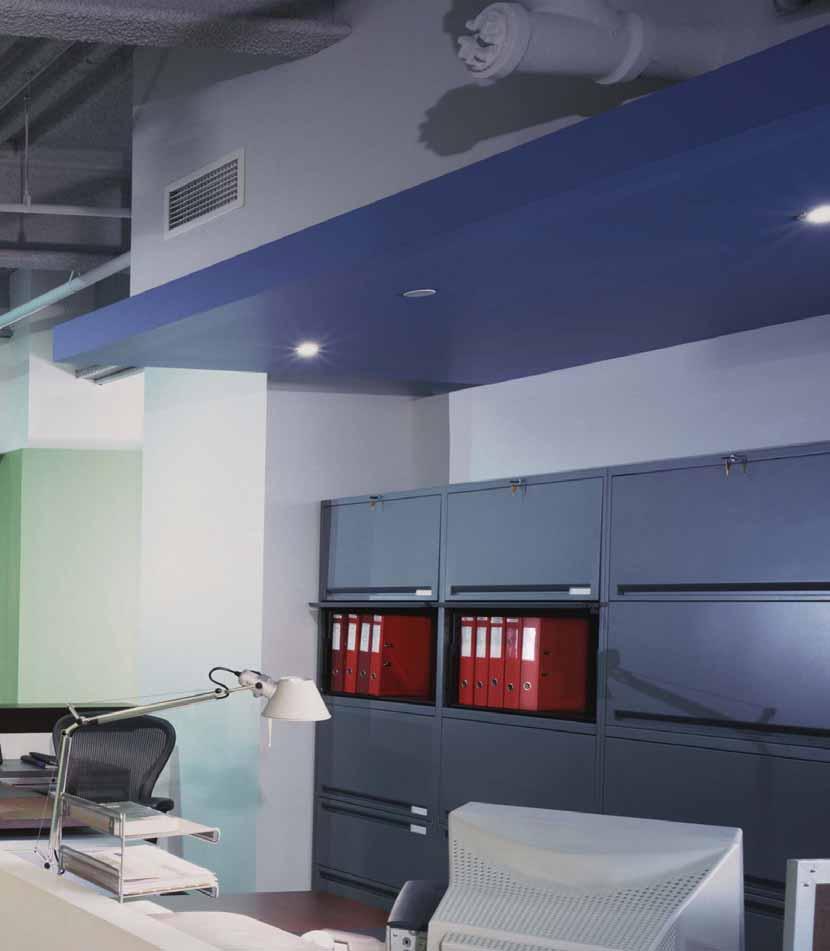
140 C140

141 Isolé IDP-3050 Power Strip with Personal Sensor Energy-saving control system for desktop plug load equipment Eight-outlet power strip with surge protection Six outlets are controlled by occupancy; two outlets are uncontrolled Personal sensor signals controlled equipment on and off based on occupancy PROJECT LOCATION/TYPE Product Overview Description The Isolé IDP-3050 is an energy-saving control system that provides maximum surge and noise suppression while keeping plug load equipment off when there is no occupancy. It consists of an eightoutlet power strip and a personal occupancy sensor. Operation Surge Suppression The power strip provides a high degree of surge suppression that protects connected equipment against threats like power surges, lightning strikes and voltage spikes. It features a resettable circuit breaker and two LEDs that indicate that the outlet is wired and grounded properly and the surge protection is functioning. Plug Controls Features The IDP-3050 turns plug load devices on and off based on occupancy. The personal sensor connects to the eight-outlet power strip with the attached cable. The power strip contains six outlets controlled by occupancy and two outlets that are uncontrolled. The IDP-3050 automatically turns all controlled devices on when the workspace is occupied, and off when the workspace has been unoccupied for the user-defined time delay. Uncontrolled devices remain on regardless of occupancy. Power Strip Eight outlets; six controlled, two uncontrolled Surge and noise suppression protects desktop equipment Ground protected for safety; will not operate without a grounded outlet Two LEDs to indicate: 1) correct wiring and grounding; 2) surge protection is functioning Installation requires no hardwiring Flat offset plug for wire management One uncontrolled outlet and one controlled outlet are wall-transformer-enabled Plugs into a standard three-prong outlet Application The IDP-3050 is ideal for controlling task lighting and computer monitors. Additional devices for the controlled outlets include space heaters, fans and other equipment that can be turned off during unoccupied periods. Devices such as CPUs and fax machines should be plugged into the uncontrolled outlets. Applications include workstations, open office cubicles, offices and engineering stations. Personal Sensor Uses latest passive infrared (PIR) technology to detect occupancy User-adjustable time delay of 30 seconds to 30 minutes Multi-level Fresnel lens for superior occupancy detection 120 coverage, up to 300 square feet ASIC technology reduces components and enhances reliability Instantaneous response time C141
142 Specifications Power Strip: Electrical rating: 120VAC, 12A, 50/60 Hz 12A dry contact relay 6 ft. black cord Transformer provides power to sensor Mounts with screws or double-sided tape UL rd Edition rating: 600V Circuit: High-energy, multistage hybrid Noise filtration: 0-25db (94.38%) Joule rating: 740 joules Maximum surge amperage: 48,000 Amps Protection modes: 500V L-N, 600V L-G, 600V N-G Response time: instantaneous Let-through voltage: 140V Initial clamping voltage: 200V UL and cul listed Five year warranty Personal Sensor: 9 ft. connector cable Supply voltage: 12 VDC 30 sec. to 30 min. Time Delay via Trim Pot (30 min. default) UL and cul listed Five year warranty Controls & Mounting Product Controls two uncontrolled outlets LED indicators on/off switch Personal Sensor Mounting six controlled outlets Double-sided tape or Self-taping screw Coverage Ordering Information Side Coverage Pattern Catalog No. IDP-3050-A DI-110 Products are dark grey LED (blinks when occupancy detected) Occupancy sensor lens Description Eight-outlet power strip with personal sensor Auto-on personal sensor Sensor mounts under desk or binder bin with double-sided tape or self-taping screw Overhead Coverage Pattern Plug Controls Pub. No rev. 5/ C142


143 OUTDOOR Controlling lights outdoors is just as important as indoors. With WattStopper s outdoor motion sensors, building owners not only save energy, they achieve a safer, more secure environment. Outdoor sensors turn lights on when a person or vehicle enters the area, and off after the space is vacated. Designed for use in all weather conditions, the raintight and weatherproof sensors mount anywhere under an eave or on a wall without overhead covering. C143

144 C144

145 EW Outdoor Motion Sensor Optional model with lampholders Rated for use in temperature range of -40 to 130 F Isolated relay enables interface with security systems or other loads Adjustable light level and time delay settings Weatherproof and raintight for reliable performance 270 degree field of view PROJECT LOCATION/TYPE Outdoor Product Overview Description WattStopper s EW outdoor motion sensors provide occupancy based control of outdoor lighting. Raintight and rated for -40 F to 130 F, EW sensors perform reliably in all weather conditions. Operation EW sensors operate at line voltage and can be mounted onto a standard, outdoor junction box. Utilizing advanced PIR technology, the sensors detect the difference between infrared energy in motion and the background space to turn lighting on when a person or vehicle enters the coverage area. After the area is vacated and the time delay elapses, lighting automatically turns off. The EW s dual PIR detectors and three level lens increase the detection density as well as the accuracy of motion detection. Lampholders For situations when a complete outdoor sensor package is desired, the EWF models include durable, polycarbonate lamp holders that accept PAR 20 or 38 lamps. They are UV and impact resistant and are impervious to weathering. The EWF features a unique dual-adjustment aiming system that allows the lamps to be angled and locked into position without the use of tools. The lamp holders unique silicon seals allow them to be aimed above horizontal in damp or wet areas. Applications Applications for commercial settings include walkways, parking lots, dock lighting and warehouses. Typical uses outside a home include garages, backyards, entrance ways and porches. Features Sensors can be mounted on walls, eaves, or ceilings for installation convenience 270 coverage Front rotates for easy coverage adjustment Precision, double-shot tooling with internal silicon gaskets prevents water and dust contamination No tools needed to aim or adjust lamp holders for speedier installation Optional override-on to turn lights on remotely for the length of the time delay ON/OFF control based on daylight levels via adjustable light level setting Zero crossing circuitry reduces stress on the relay and results in increased sensor life ASIC enhances reliability and helps to eliminate false triggers Pulse Count Processing eliminates false triggers and provide RFI and EMI immunity Patented Voltage Drop Protection Solid state digital microprocessor offers increased reliability User-adjustable time delay from 12 seconds to 16 minutes C145
146 Specifications 120 VAC or 277 VAC operation UL 773A rated raintight; UL 1571 rated for wet locations Operating temperature: -40 to 130 F (-40 to 54 C) Adjustable light level of 0.5 to 200 footcandles (5.4-2,152.8 lux) Isolated relay with N/O and N/C outputs; rated for 1 30 VDC/VAC (EW-200) 1/2 threaded nipple fits standard NEMA weatherproof fixture fitting Lamp holders use PAR 20 or 38 lamps, up to 150W each lamp* Compatible with all electronic ballasts and PL lamp ballast systems Sensor dimensions: 6.7 x 3.2 x 2.2 (170mm x 80mm x 55mm) UL and cul listed Five year warranty Wiring, Mounting & Installation Wiring Diagram Line Switch (optional) Sensor () Mounting Diagrams Lighting Wall or pole mounting Ceiling/eave mounting Installation & Positioning Sensor with Lampholders Coverage Coverage Pattern 90 EW-200 Series Coverage (270 ) Outdoor 8ft (2.4m) 9.5ft (3m) 25ft (8m) 52.5ft (16m) Ordering Information Catalog No. Color Voltage Rating Coverage Features EW W Arctic white 120 VAC; 60 Hz watt ballast, 270 Isolated relay EW G Arch. grey tungsten EW W Arctic white 277 VAC; 60 Hz watt ballast 270 Isolated relay EWF W Arctic white 120 VAC; 60 Hz * watt ballast, 270 Lamp holders tungsten *The sensors with lamp holders may use up to 300 watts for lamps even though they have a watt load rating Pub. No rev. 10/ C146

147 EW Low Voltage Outdoor Motion Sensor 24 VDC operation Rated for use in temperature range of -40 to 130 F Adjustable light level and time delay settings 270 degree field of view Works with DM-105-WP for high/low control of outdoor HID lighting Weatherproof and raintight for reliable performance PROJECT LOCATION/TYPE Outdoor Product Overview Description WattStopper s EW outdoor motion sensors provide occupancy based control of outdoor lighting. Raintight and rated for -40 F to 130 F, EW sensors perform reliably in all weather conditions. Operation EW sensors operate at 24 VDC and are mounted onto a standard, outdoor junction box. Utilizing advanced passive infrared (PIR) technology, the sensors detect the difference between infrared energy in motion and the background space to turn lighting on when a person or vehicle enters the coverage area. After the area is vacated and the time delay elapses, lighting automatically turns off. The EW s dual PIR detectors and three level lens increase the detection density as well as the accuracy of motion detection. Applications The low voltage EW sensors are ideal to use in conjunction with WattStopper DM-105-WP outdoor HID control module. Here, the EW allows the outdoor HID lighting to switch between high and low based on motion detection. Applications include walkways, parking lots, dock lighting and warehouses. When used with a power pack, the low voltage EW also provides an outdoor lighting control solution for areas where line voltage is not available or where the load is too large for a single line voltage sensor to handle. Features Sensors can be mounted on walls, eaves, or ceilings for installation convenience 270 coverage pattern Front rotates for easy coverage adjustment Precision, double-shot tooling with internal silicon gaskets prevents water and dust contamination Optional override-on to turn lights on remotely for the length of the time delay User-adjustable time delay from 12 seconds to 16 minutes Adjustable light level setting allows users to set the level at which lighting will turn on upon occupancy ASIC enhances reliability and helps to eliminate false triggers Pulse Count Processing eliminates false triggers and provide RFI and EMI immunity Includes hardware for mounting sensor to standard 4 round outdoor junction box C147
148 Specifications Wiring & Installation Operating temperature range -40 F to +130 F UL 773A rated raintight 24 VDC operation 270 coverage Adjustable light level of 0.5 to 200 footcandles (5.4-2,152.8 lux) Installation & Positioning 1/2 threaded nipple fits standard NEMA weatherproof fixture fitting Sensor dimensions: 6.7 x 3.2 x 2.2 (170mm x 80mm x 55mm) UL and cul listed Five year warranty Mounting Diagrams Wall or pole mounting Ceiling/eave mounting EW Wiring with DM-105-WP HID Control EW and Power Pack Wiring EW Sensor 24VDC Control Output from Sensor Common (Return) from Sensor +24 VDC Out to Sensor Blue N Hot (Line) Power Pack () () Switch Lighting Ballast Blue CAP CAP WH/BLUE BLACK WHITE WH/ORG DM-105-WP Control Output 24VDC (BLU) Control Return (BLK) +24VDC (RED) EW Sensor Coverage Coverage Pattern EW-205 Coverage (270 ) Outdoor 90 8ft (2.4m) 9.5ft (3m) 25ft (8m) 52.5ft (16m) Ordering Information Catalog No. Color Voltage Current Coverage EW W Arctic white 24 VDC 7 ma 270 EW G Arch. grey 24 VDC 7 ma 270 Pub. No rev. 11/ C148


149 ACCESSORIES Specialty accessories include mounting brackets and cages for optimizing sensor installation. In addition, take advantage of data loggers to identify expected energy savings from occupancy sensor installation. Finally, consider card key switches for a unique energy-efficient control solution in spaces such as hospitality and healthcare guestrooms. C149
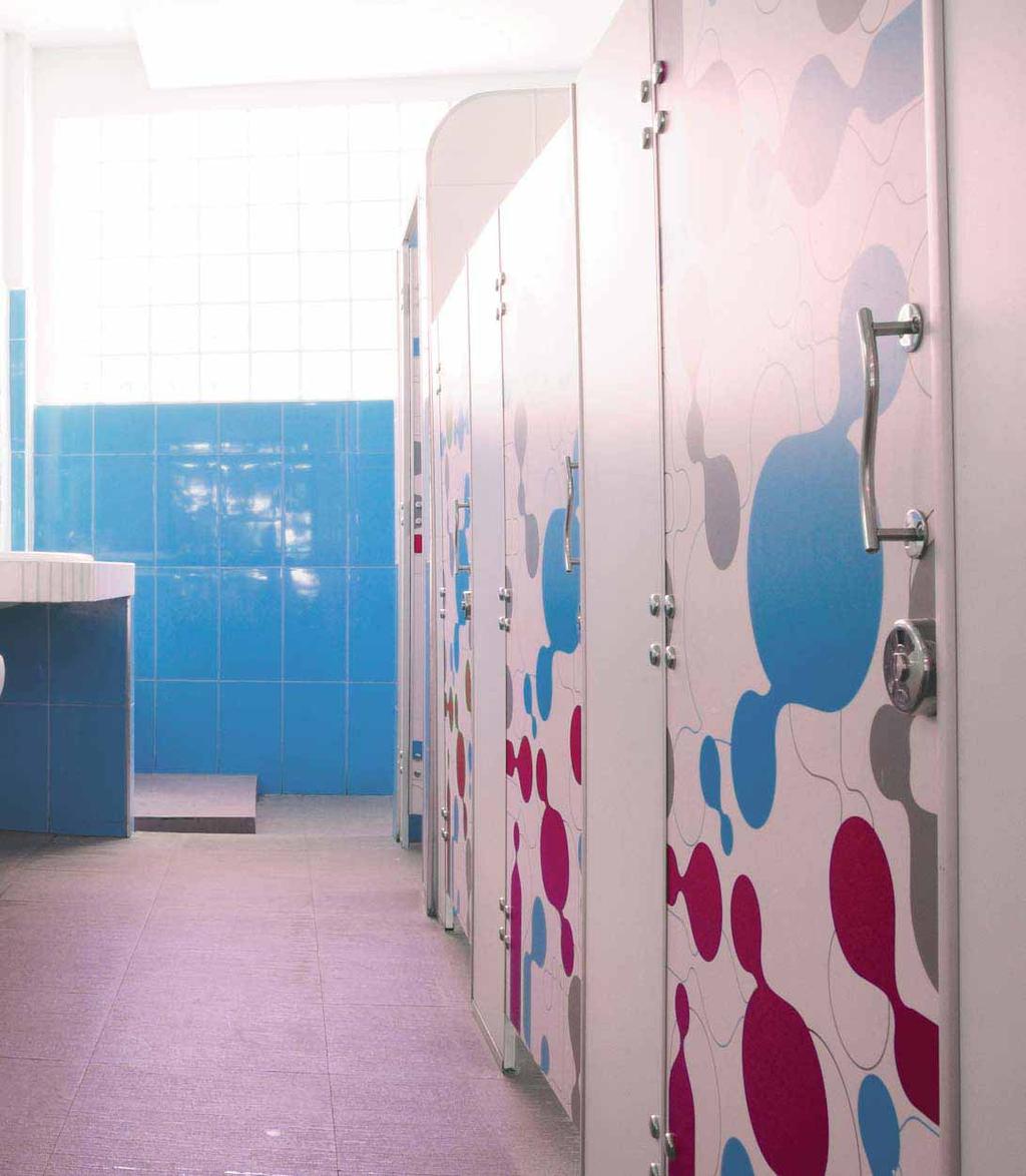
150 C150
 Built-in bubble level for accurate installation PROJECT LOCATION/TYPE Product Overview Description The MB-1 and MB-2 are durable mounting brackets used to install occupancy")

151 MB Sensor Mounting Brackets Brushed aluminum construction Mounting plates adjustable to preset angles Multiple mounting options with MB-1 Compatible with most WattStopper occupancy sensors HID fixture bracket (MB-2) Built-in bubble level for accurate installation PROJECT LOCATION/TYPE Product Overview Description The MB-1 and MB-2 are durable mounting brackets used to install occupancy sensors in a variety of settings. Both brackets include adjustable plates that allow sensor rotation to achieve the desired angle for optimal coverage. The brackets also include built-in bubble levels that afford the installer reliable guides to ensure the bracket is correctly positioned before adjusting the sensor. The MB-1 and MB-2 are constructed of aluminum with a clear powder coating finish. MB-2 With the MB-2, sensors can be attached directly to High Intensity Discharge (HID) fixtures, mounting to the bottom rim of the HID reflector bell and secured to the rim with three clamping screws. Sensors recommended for use with the MB-2 bracket include the CX, CI and HB sensors. The MB-2 includes a J-shaped bracket and a sensor mounting plate. The MB-2 also comes with extension wires that can be used, if needed, to connect the attached sensor to the DM HID controller. MB-1 Bracket Diagrams Accessories The MB-1 bracket enables users to mount sensors to a variety of structures, including fluorescent fixtures, walls, shelves, and girders. Among the many sensors compatible for use with the MB-1 bracket are the WPIR, CX, CI, and HB sensors. The MB-1 features an L-shaped bracket and a sensor mounting plate. When installed, this mounting plate can be rotated to direct the sensor toward the floor or along an aisle way at up to a 33 angle. In addition, the L-shaped bracket can be molded or reshaped to provide other mounting options. CX sensor on HID fixturemounted MB-2 bracket CX CX sensor mounted on MB-2 bracket HB sensor mounted on MB-2 bracket (girders) Ordering Information Catalog No. MB-1 MB-2 Description L-Plate Industrial Mounting Bracket J-Plate HID Mounting Bracket Mounting options for MB-1 bracket C151 Pub. No rev. 10/2009 HB sensor mounted on MB-1 bracket (fluorescent fixtures)


 Fits: DT-200, CX-100, CB-100 for wall mounts WC-3 4.92 (125.0mm) 5 (127.")
 6.8 (172.7mm) Ordering Information 5.4 (137.2mm) 2.52 (64.")
152 Protective Cage for Occupancy Sensors Helps prevent occupancy sensors from being tampered with or damaged Constructed from strong, durable coated steel wire Simple installation PROJECT Product Overview Description LOCATION/TYPE WattStopper protective wire cages enclose our occupancy sensors in a safe cage that prevents the units from being tampered with or damaged. The cages use a strong, durable, web-like design and are constructed with 3/16 coated steel wire. They are ideal for installation in gymnasiums, racquetball courts, classrooms and other institutional facilities, or any area susceptible to vandalism. They are low in cost and simple to install. By protecting occupancy sensors from damage, they also reduce maintenance costs. Specifications WC-1 WC (161.0mm) 9.18 (233.2mm) Fits: DT-200, CX-100, CB-100 for wall mounts WC (125.0mm) 5 (127.0mm) Fits: DT-200, CX-100, CB-100 for corner mounts WC (175.5mm) 4.18 (106.2mm) Accessories 5.4 (137.2mm) 6.8 (172.7mm) Ordering Information 5.4 (137.2mm) 2.52 (64.1mm) Fits: W-500A, W-1000A, W-2000A, W2000H, WT, CI-200, WPIR, DT-300, UT-300, CI-300 Catalog No. WC-1 WC-2 WC-3 WC (104.1mm) 2.32 (58.9mm) Fits: PW, UW, DW, WS, WN, WD, AS, TS Pub. No rev. 10/2009 C152

153 IT-200 InteliTimer Pro Logger Determines energy savings potential from occupancy sensor use Adjustable light pipe observes lighting level IT-ProSoft Software provides single-step data retrieval, storage, analysis, printing Lithium battery with average life of 10 years Logs when a space is occupied/vacant and when lighting is on/off PROJECT LOCATION/TYPE Small and lightweight for ease of use and portability Accessories Product Overview Description The InteliTimer Pro (IT-200) is a revolutionary occupancy and light logger that establishes the energy saving potential when using occupancy sensors. With this versatile tool, spaces for lighting control use can be pinpointed and savings can be verified. Operation The IT-200 records a log entry every time there is a change in either the occupancy status or lighting status and stores a detailed history of these events for retrieval by PC. It utilizes passive infrared technology to detect occupancy. It observes the light level through a clear, plastic light pipe to determine if lights are on or off. The logger distinguishes artificial lighting from natural lighting to give accurate lights-on readings. To log data, a user places the logger so that its lens has a clear view of the workspace and the light-pipe aims towards the nearest light fixture. Software Included with the IT-200 is IT-ProSoft 2.0 software. In a single keystroke or mouse click, users can retrieve, store, analyze, or print data reports. These reports can be directly exported to Microsoft Excel for further analysis. IT-ProSoft also enables users to operate multiple units in multiple locations while ensuring that each logger s identity and logging site information will be correctly merged. Once the logged information is retrieved, the unit can be reset and used to log information at another test site. Users may group logging data from different areas and automatically receive separate reports by utilizing the IT-200 s bookmarking feature. Applications The IT-200 offers a simple and cost-effective method of auditing any building space for wasted lighting. Since the logger is portable and battery operated, it is convenient to quickly move it from one location to download to a computer, and on to the next location for another logging session. Features Reports show graphs of occupancy and lighting and projects savings and statistical information Users set logging parameters for more accurate savings projection Powered by a lithium battery, with an extended life span of approximately ten years Small and lightweight for ease of use and portability Installs quickly and conveniently and requires no wiring IT-ProSoft 2.0 operates in six languages (English, French, German, Spanish, Swedish, and Norwegian) with appropriate currency/ date/time formats, and energy and HVAC defaults Occupancy detection LED helps users confirm that logger is detecting motion in desired space Light level LED helps users set logger to identify the on and off lighting levels of different locations The LEDs work for a 60 second test period to preserve battery life C153
154 Specifications InteliTimer Pro Lithium battery operated. Average battery life ~ 10 years. Battery life indicator Test button activates LEDs for 60 seconds during which sensitivity is set and proper location for occupancy detection is verified LED blinks during occupancy detection Green LED blinks when lighting is detected Recessed reset switch Coverage up to 150 ft 2 (45.7m 2 ) Stores a maximum of 4096 entries Stores site name to identify the area being monitored Connects to computer (PC) for data retrieval via serial connector cable Includes a serial to USB adapter for computers without serial ports IT-ProSoft Software Lists all log entries: entry number, date/time of entry, lighting status, occupancy status Users set logging parameters (energy cost/ kwh, size of load, site name, sensor time-outs) for more accurate savings projection Reports show daily graphs of occupancy and lighting data, and lighting/occupancy analysis projecting savings and statistical information HVAC factor enables calculation of additional potential savings due to reduced HVAC load While connected, software can reset the logger in preparation for a new logging session Merge log capability combines outputs from multiple loggers monitoring a single location Compatible with Windows XP Professional with SP3, Windows Vista Business, and Windows 7 Professional (32 or 64-bit) Downloadable at Controls & Installation Product Controls Light pipe Occupancy sensor lens Light level sensitivity adjustment T-bar Ceiling Installation CEILING TILE T-Bar Reset button Test button (activates LEDs) LED (occupancy) Data connector port Green LED (light) The IT-200 simply clips to a T-bar of a ceiling tile - no wiring is needed. For installation onto other surfaces, the unit comes with a flat bracket and double-stick tape. Coverage & Software Reports Logged Entries Report Entries: 42 From: Sun, Aug 14, 1995 at12:00:00 PM To: Thu, Aug 18, 1995 at 9:32:00 PM Office Placement Example Cost/kWhr: $0.080 HVAC Adder: 15% Size: 180W 1 Sun, Aug 14, 1995 at12:00:00 PM Lights ON Occupied 2 Sun, Aug 14, 1995 at 2:25:00 PM Lights ON Vacant 3 Mon, Aug 15, 1995 at7:50:00 AM Lights ON Occupied 4 Mon, Aug 15, 1995 at10:15:00 AM Lights ON Vacant 5 Mon, Aug 15, 1995 at10:50:00 AM Lights ON Occupied 6 Mon, Aug 15, 1995 at12:15:00 PM Lights OFF Vacant The IT-200 monitors an area of up to 150 ft 2 (13.9m 2 ). The unit should be placed near the light source with the light pipe aimed at the light and the lens facing the occupant s main work area. Lighting & Occupancy Graph Graphs of Ligh ting/occupancy for Oce Suit e #301 Date of Entr ies Midnight 06:00 AM Noon 06:00 PM Monday January 8 graph indicates Monitored Area Lit Lighting & Occupancy Graph ON+Occupied: hours ON+Vacant: hours OFF+Occupied: 0 hours OFF+Vacant: hours graph indicates Monitored Area Occupied LIGHTING/OCCUPANCY SUMMARY 17.8% 24.0% 0.0% 58.2% Accessories Ordering Information Catalog No. IT-200 Description Occupancy and light logger with software for PC Pub. No rev. 10/2013 All units are white C154

155 HS Series Card Key Switches Room key activated master switch for hotel guest room lighting Line and low voltage models Facilitates energy savings in hotels, motels and boarding houses Backlit card key slot for visibility in darkened rooms 30-second egress time Optional key fob for rooms that do not use a card key PROJECT LOCATION/TYPE Product Overview Description The HS Series Card Key Switch turns electrical circuits on or off when a card key or HS-FOB Key Fob is inserted or removed from its slot. Operation Inserting a door entry card key or HS-FOB into the HS Card Key Switch energizes the controlled circuits and loads. Removing the card key initiates a 30-second time delay to allow safe egress from the hotel room. Once this time delay elapses, the power to the circuits is terminated. To restore power to the room s controlled circuits, reinsert the card key into the HS Card Key Switch. Low and Line Voltage Models The HS-100 is a low voltage unit with a normally open and normally closed isolated relay, allowing it to interface with third-party energy and lighting management control systems. Additionally, the HS-100 can connect to one or more WattStopper Power Pack(s). The HS-150 is a line voltage unit that serves as a master switch for a single guest room circuit. Applications HS Card Key Switches are ideal for guest rooms in hotels, motels, boarding houses, senior residences or similar applications with guest rooms. Once installed, they function as control devices located at the main entry door, controlling all permanently installed luminaires. Features Attractive low-profile styling Choice of five decorator colors Backlit card key slot provides visibility in darkened rooms 30-second egress time delay Zero crossing for reliability and increased product longevity (HS-150) HS-100 can connect with one or more WattStopper Power Packs Uses the same card key that unlocks the door Compatible with Building Automation Systems, Energy Management Systems, and Lighting Control Panels C155
156 Model # GROUND Model # Santa Clara, CA LISTED 58GK Photoelectric Switch Santa Clara, CA VAC, 50/60Hz Relay Output: 0-800W tungsten/ballast, 1/6hp@120VAC W ballast, 1/4hp@277VAC Indoor use only APPLIANCE CONTROL 88T9 GROUND LISTED 58GK Photoelectric Switch Specifications HS-100: Input: 24VDC/24VAC Half Wave Rectified, Max. 25mA DC/10mA AC Output: 1A/30VDC/VAC SPDT Isolated Relay HS-150: 120/277 VAC; 50/60Hz W tungsten and ballast, 500W compact fluorescent, 1/2hp W ballast Zero crossing (HS-150) Egress time delay: 30 seconds Compatible with building automation/energy management systems, lighting control panels and WattStopper power packs Dimensions: 2.63 x 1.69 x 1.88 (67.8mm x 42.9mm x 47.8mm) L x W x D Accepts standard hotel card keys with dimensions of: W x H x D (53.975mm x mm x mm) UL and cul listed Five year warranty Installation & Wiring HS-100 Wiring with Power Pack Hot/Line N.C. HS-100 Card Key Switch Input: 24VDC/24VAC Half Wave Rectified Output: 1A/30V SPDT Isolated Relay Indoor use only COMM RLY COMM HS-150 Wiring N.O. +24V IN RLY COMM N.O r1 24V IN COMM Ground HS-100 Card Key Switch () (Line) Power Pack Blue * () Do not wire receptacles directly to HS-100; device is not rated to control receptacles. * Do not exceed the power pack s maximum load rating. C Normally open contactor electrically held 120 VAC Supply Circuits Local OFF switches Lighting load Lighting load Lighting load Controlled receptacles inside the room 3.37 (85.5mm) HS-100 with BAS or LCP Model # HS-100 Santa Clara, CA Card Key Switch Input: 24VDC/24VAC Half Wave Rectified Output: 1A/30V SPDT Isolated Relay Indoor use only GROUND N.C. COMM RLY COMM N.O. +24V IN RLY COMM N.O r1 N.C. +24V IN COMM Cover Plates and Key Fob Lighting control panel or other building control system Hot/Line Ground HS-150 Card Key Switch HS-150 Card Key Switch Do not wire receptacles directly to HS-150; device is not rated to control receptacles. * Do not exceed the HS-150 s maximum load rating 08363r1 * () From Power Panel C Normally open contactor electrically held Local OFF switches Lighting load Lighting load Lighting load Controlled receptacles inside the room 4.7 (119.38mm) 2.51 (63.8mm) 2.63 (67.8mm) HS-WP HS-FOB 6.36 (161.65mm) HS-WPR 6.36 (161.65mm) HS-WPL Ordering Information Catalog No. Color Description HS-100-W Low voltage HS-100-LA Light Almond Card Key Switch HS-100-I Ivory HS-100-B HS-100-G Gray Accessories HS-FOB-W Optional Key Fob for HS-FOB-LA Light Almond guest rooms that are not HS-FOB-I Ivory equipped with card key HS-FOB-B locks HS-FOB-G Gray Catalog No. Color Description HS-150-W HS-150-LA HS-150-I HS-150-B HS-150-G Light Almond Ivory Gray Line voltage Card Key Switch HS-WPR-W Cover plate for three- HS-WPR-LA Light Almond gang box with decorator HS-WPR-I Ivory switch option; card slot HS-WPR-B on the right HS-WPR-G Gray HS-WP-W HS-WP-LA HS-WP-I HS-WP-B Light Almond Ivory Cover plate for singlegang box HS-WPL-W HS-WPL-LA HS-WPL-I HS-WPL-B Light Almond Ivory Cover plate for threegang box with decorator switch option; card slot on the left HS-WP-G Gray HS-WPL-G Gray Pub. No rev. 10/2013 One HS-WP included with each Card Key Switch C156


157 DAYLIGHTING WattStopper leads the industry in innovative automatic daylighting control, one of the most effective ways to capture additional potential energy savings. Choose from On/Off switching or dimming closed loop stand-alone devices for single zone control. For system based daylighting controls refer to Digital Lighting Management (Section A) in this guide. C157

158 C158

159 LightSaver LS-102 Switching Photosensor Single zone, on/off switching photosensor Automatic setpoint selection Automatic startup/calibration Digital multi-band photosensor Easy-to-read LCD display and LED status indicators Multiple user-adjustable control parameters PROJECT LOCATION/TYPE Daylighting Product Overview Description The LS-102 Daylighting Controller is a single zone, on/off switching device designed to be installed in a closed loop application. A self-contained 24 VDC device with an extended range of footcandles, the LS-102 requires a low voltage power pack to operate. The controller consists of an advanced digital multi-band photosensor, an on-board microcontroller, and an LCD display. This photosensor is positioned behind a 100º cone that cuts off unwanted light, preventing false triggers. Operation Setpoints can be selected either automatically or manually. When ambient light levels exceed the off setpoint, the controller turns lighting off. It will turn lighting systems back on when the on setpoint is triggered. Because of its automatic calibration feature, many applications require little or no adjustment of the settings. The LS-102 can be paired with a low voltage wall switch to enable manual override, or with an occupancy sensor to enable its Hold On While Occupied feature. Automatic Startup/Calibration The LS-102 features automatic setpoint calculations. The device initiates a procedure to select an appropriate value for the on setpoint. As part of the process, the controlled load is first turned on for a brief interval to warm up the lamps, and then switched off. This process is repeated several times. At the completion of the calibration, a new value for the on setpoint will have been selected. Other adjustable settings include deadband and time delay settings. If desired, the deadband can be adjusted to a value of 25, 50, 75, or 100 percent above the setpoint. The time delay can be adjusted to 3, 10, 20 or 30 minutes. Applications The LS-102 Daylighting Controller can be used to control any type of lighting: incandescent, fluorescent, compact fluorescent (CFL), HID, and LEDs. The devices work in peripheral offices, skylit areas, cafeterias, warehouses and any other indoor area with natural light contribution. Features Easy-to-read LCD display prompts installer through set-up Four user-adjustable parameters: on setpoint, off setpoint, off setpoint time delay, and Hold On While Occupied Mode (if wired with an occupancy sensor) Test mode overrides programmed time delay, enabling installer to verify accuracy of settings Control load status verification allows testing and confirmation that wiring is correct Form factor designed to eliminate misalignment LED status indicator identifies when device is in override or test mode, or if device has switched lights on or off Mounting options for top- or side-lit applications One-hour manual override capability (when wired with low voltage, pushbutton wall switch) Programmable in most daylight conditions Qualifies for use on ARRA-funded public works projects C159
160 Specifications Wiring, Installation & Location Automatic setpoint calculation Digital Multi-Band Photosensor Range: footcandles ON Setpoint Range: footcandles Status Indicator: Multi-function green LED Power Requirements: 12/24 VDC; 7 ma typical Output Signal: 24VDC; maximum 120 ma Wiring Diagram Neut. Hot/Line 120/277VAC Any 24VDC Occupancy Sensor Blue BZ-150 Power Pack Blue Brown Orange Grey LVS-1 Switch or Equiv. (Optional) Control Out Blue +24VDC in Common Occupancy Input /Yellow (cap if not used) Lighting Cap both wires, not used For other wiring diagrams, please visit the CAD Resource Center at LS-102 Location: Suitable for dry interior locations Environment: ºF (0-49ºC), less than 90% relative humidity Dimensions: 2.4 diameter x 0.7 deep (61mm x 17mm) Five year warranty UL listed Mounting and LED Display Menu Button Light Sensor Mounting Screw Hole FC 57 Status LED Display Mounting Screw Hole Retaining Nut Plastic Washer Ceiling Select Button Side Lighting Application Top Lighting Application LS-102 Skylight LS-102 Light Fixture Window Light Fixture Deadband Level Chart Footcandle Peak Sensitivity Typical Daylit Zone, about 12' (3.6m) OFF Setpoint Deadband Energy Savings Opportunity Daylight Electric Light ON Setpoint 8am 9am 10am 11am 12pm 1pm 2pm 3pm 4pm 5pm 6pm 7pm 8pm 100 If the LS-102 s photosensor lighting level drops below the on setpoint, the lights will remain on. If the sensor s lighting level rises above the off setpoint, the LS-102 will automatically turn the lights off. If the sensor s lighting level remains in the predetermined deadband range (25%, 50%, 75% or 100%) the lighting will be passive until the sensor s level reaches the high or low setpoints. Daylighting Time Ordering Information Catalog No. Description LS-102 On/Off Switching Photosensor LS-102-U On/Off Switching Photosensor, ARRA-compliant* *Product produced in the U.S. Footcandle Range fc fc Deadband Adjustment Range 25%, 50%, 75% & 100% above on setpoint 25%, 50%, 75% & 100% above on setpoint Pub. No rev. 5/ C160

161 LightSaver LS-301 Dimming Photosensor Automatic dimming based on ambient light levels Controls standard 0-10 VDC electronic dimming ballasts or compatible LED drivers All setup performed remotely with handheld Optional occupant adjustment via handheld remote Single zone control Closed loop daylighting control PROJECT LOCATION/TYPE Daylighting Product Overview Description The LightSaver LS-301 is a closed loop, ceiling mount, low voltage indoor photosensor that works with standard, 0-10 VDC electronic dimming ballasts or compatible LED drivers to dim lighting as daylight increases. Operation The LS-301 mounts on a ceiling and utilizes a spectral filtering system to measure daylight and electric light levels. A closed loop daylighting system, the LS-301 measures the total light level from daylight and electric light in the controlled area to adjust electric lighting levels. As the daylight contribution increases, the lights dim down. The photosensor utilizes sliding setpoint control, which responds to the different spatial distribution qualities of electric light and daylight. The LS-301 calculates the required light level for current daylight contribution based on two setpoints. One represents the target level when no daylight is present (night setpoint) and the other when significant daylight is present (day setpoint). Adjustment via Handheld Remote Control All LS-301 adjustments are made with one of two handheld remotes. The LSR-301-S provides five buttons for initial set-up, which is easily completed by first raising or lowering electric light levels to desired levels, then programming this target level into the photosensor. The LSR-301-P provides three buttons for occupants to adjust light levels. With this optional tool, users can increase target light levels by up to 25% or reduce them to the lamp/ballast minimum level. Pressing the Auto button returns the control to programmed levels. Applications The LS-301 is designed to blend into its surroundings when installed in any environment. It provides one zone of daylighting control in a private office or classroom. In these applications, the LS-301 can be combined with an occupancy sensor. Often, it is possible for the LS-301 to share a single power pack with occupancy sensor(s). Features Provides precise control of lighting to maintain desired light level Extremely linear photocell response with greater than 1% accuracy Designed to measure light as the human eye perceives it, eliminating overreporting illumination levels provided by daylight California Title compliant Separate handheld remote controls for setup and occupant adjustment to prevent tampering Boosts energy savings by reducing maximum lamp output, often resulting in a 20% reduction or more compared with lights at full output Achieves lumen maintenance by holding target light level as lamp output decreases over time Qualifies for use on ARRA-funded public works projects C161
162 Specifications Full range dimming:.2 VDC (minimum) to 10 VDC (100% lighting) output voltage Current consumption: VDC In typical applications, setpoints are adjustable from footcandles ( lux) Controls up to 50 standard dimming ballasts in one zone Sensor leads: gray and violet to dimming ballast, red and black to 24 VDC Dimensions: 2.35 diameter. x depth (60mm x 22mm), threaded piece extends 1.25 (31.8mm) from back, fits.5 knockout Five year warranty Product Controls Wiring & Installation Coverage Remote Controls NIGHT AUTO DAY Wiring 6ft. min. 4ft. min. LSR-301-S Photosensor Setup Tool LS-301 Vio (+) Gray (-) Lighting Nighttime setpoint Auto button for automatic dimming Raise/lower light levels Daytime setpoint Vio Gray Yel Yel Window LS-301 Electronic Dimming Ballast Lamp Lamp Lens Orientation () () Blue Blue Lighting AUTO Remote handheld (left) enables easy set-up while optional occupant remote provides adjustability for individual lighting preferences. LSR-301-P Personal Remote Control (Line) Power Pack Blue Control Output 24VDC +24VDC (in) Common Spectral Response Curve Relative Sensitivity (%) Hot Neut. Any 24VDC Occupancy Sensor Placement Guidelines Mount photocell between 6 and 12 feet (1.8m - 3.7m) from window. Do not mount directly above direct/indirect pendant fixtures. Mount at least 4 feet (1.2m) from pendant fixtures Wavelength (nm) The spectral response of the LS-301 photocell closely matches the sensitivity of the human eye. Mounting and Installation Retaining Nut Plastic Washer Ceiling Daylighting Ordering Information Catalog No. Description Input Voltage LS-301 LS-301-U LSR-301-S LSR-301-P Dimming Photosensor Dimming Photosensor, ARRA-compliant* Setup Remote Control Occupant Remote Control LS-301 works with WattStopper power packs *Product produced in the U.S. 24 VDC 24 VDC Pub. No rev. 5/ C162
163 SERVICES Lighting Control System Services Technical services related to design and installation of WattStopper control products Free telephone technical support for purchased product(s) Extended warranties available Complete project assistance Startup and training services PROJECT LOCATION/TYPE Product Overview Description Comprehensive services include design, startup, onsite training and troubleshooting as necessary. Project Engineering Engineering services provide complete design and implementation using WattStopper products. The (SDRAWSYS) services include submittal packages with system one-line diagram (or reflected ceiling plan when applicable) showing system components and quantities for all products. Drawings can include system riser diagrams, individual panel and room controls to show hardware configuration, panel numbering and wiring schedules showing circuit/relay/load relationships as well as occupant overrides, sensors, wiring diagrams for each component, installation instructions and testing procedures for each component. SDRAWSYS provides ongoing Project Management support throughout the installation phase, through to the final startup and project acceptance. Programming Programming Services (SPROGSYS) provide custom programming for special applications requiring advanced logic and customized control solutions including BACnet integration. Graphical interface screens are customizable to enhance efficiency and provide user friendly control of the system (WCGRSCRN). Startup Highly qualified technicians are available for onsite services and maintenance assistance. Comprehensive startup service (SCOM) includes a WattStopper factory-trained technician to verify that all WattStopper system hardware on the bill of material (including standalone occupancy sensors) is installed and configured in accordance with product documentation and project requirements. The service tests and verifies systems are operating as intended, implements sequences of operation (SOO) as directed, or provides a basic starting program configuration. SCOM also includes owner training to review programming, operation and maintenance. Alternate startup service (SCOMEXSEN) provides a WattStopper factory-trained technician to verify all WattStopper system hardware except standalone occupancy sensors as described above. Other services are available to assist commissioning agents with testing, provide system troubleshooting and repair, implement system upgrades or energy optimization, and perform auditing. Training Additional training services (STRAIN) include a WattStopper factory-trained technician to provide additional and separate site visits to conduct system training to review all system hardware, software, and adjustments. C163

 Onsite")

164 Sample Project Engineering Documents SERVICES Sample Graphic Interface Screens Ordering Information Catalog No. SDRAWSYS SPROGSYS WSGRSCRN SCOM SCOMEXSEN STRAIN SERVICE HWARRANTY-1 Description Factory project engineering services Custom factory programming Custom graphic interface screen(s) Onsite startup/training for all WattStopper products Onsite startup/training excluding occupancy sensors Day(s) Onsite training for WattStopper control products On-site support for commissioning assistance, system optimization, troubleshooting and repair Year(s) extended warranty for hardware Pub. No rev 9/ C164
POWER YOUR ENERGY EFFICIENCY PROGRAMS. with proven lighting controls. designed to be better.
 POWER YOUR ENERGY EFFICIENCY PROGRAMS with proven lighting controls designed to be better. CAPTURE ENERGY SAVINGS FOR YOUR CUSTOMERS AND GROW YOUR BUSINESS WITH PROVEN LIGHTING CONTROLS. Legrand s popular
Versatile wall switch sensors maximize payback and simplify code compliance
 Versatile wall switch sensors maximize payback and simplify code compliance Commercial Wall Switch Occupancy Sensors MANUAL-ON MULTI-WAY NIGHTLIGHT Achieve the best energy savings for every wall switch
Technology. Occupancy & Vacancy Sensors & Timers. Technology. Occupancy & Vacancy Sensors & Timers L-2
 Passive Infrared Sensors (PIR) Using a patented fresnel lens which minimizes optical aberrations, each Legrand/Pass & Seymour PIR sensor breaks its coverage area into zones. Upon detecting an infrared
Ceiling Mount Sensors B4-B9. Occupancy and Vacancy Sensors B10-B15 B16-B17. Wall Mount Occupancy Sensors B-1
 Occupancy and Vacancy Sensors ENERLITES offers a wide variety of lighting sensors. They are designed to bring convenience to your life and business while helping to reduce energy consumption in commercial,
Dual Relay Multi-Technology Wall Switch Occupancy Sensors
 Dual Relay Multi-Technology Wall Switch Occupancy Sensors The OSSMD line of dual relay multi-technology Decora style wall switch occupancy sensors features several models to provide automatic lighting
CS1200 WHT Pir Ceiling Mount Occupancy Sensor
 3804 South Street 75964-7263, TX Nacogdoches Phone: 936-569-7941 Fax: 936-560-4685 Catalog Number Manufacturer Description Weight per unit Product Category Features Area Coverage Field of View Load Type
Installation Instructions
 Specifications PW-100 PW-200 PW-100/PW-100-347/PW-200/PW-200-347 v3 Passive Infrared Wall Switch Occupancy Sensor PW-100-347 PW-200-347 Voltages: PW-100 & PW-200................ 120/277VAC, 50/60Hz PW-100-347
v3 360 Dual Technology Low Voltage Occupancy Sensor with Light Level, Isolated Relay and Manual On feature
 DT-300 v3 360 Dual Technology Low Voltage Occupancy Sensor with Light Level, Isolated Relay and Manual On feature Specifications Voltage...18-28VDC/VAC, half wave rectified AC Current Consumption...25
PSC-ID-x-CM Series Ceiling Mount Occupancy Sensor
 TECHNICAL SPECIFICATIONS PSC-ID-x-CM Series Ceiling Mount Occupancy Sensor Basic Features Line voltage version: 120-277VAC, 60Hz Low voltage version: 24VDC, requires separate class 2 power supply PIR sensor
Residential Occupancy & Vacancy Sensors
 Eaton s Wiring Devices Occupancy & vacancy sensors Residential Occupancy & Vacancy Sensors Simple and affordable solutions for energy savings and convenience Eaton s residential occupancy & vacancy sensors
Arrow Hart. Universal Dimmers and Sensors. Eaton s Arrow Hart. Reliable lighting control for commercial installations
 Eaton s Arrow Hart Commercial lighting controls Eaton s Arrow Hart Universal Dimmers and Sensors Reliable lighting control for commercial installations Arrow Hart Eaton s s and dimmers are cost -effective
Passive Infrared (PIR) Wall Switch Occupancy Sensor Dual Circuit
 Wall Switch Occupancy Sensor Dual Circuit") Instruction Bulletin 63249-420-418A1 02/2014 Passive Infrared (PIR) Wall Switch Occupancy Sensor Dual Circuit Commercial Grade with Ground SLSPWD1277C Retain for Future Use INTRODUCTION The Passive Infrared
Instruction Bulletin 63249-420-418A1 02/2014 Passive Infrared (PIR) Wall Switch Occupancy Sensor Dual Circuit Commercial Grade with Ground SLSPWD1277C Retain for Future Use INTRODUCTION The Passive Infrared
Installation Instructions
 DT-300 360 Dual Technology Low Voltage Occupancy Sensor with Light Level, Isolated Relay and Manual On features Specifications Voltage................18-28VDC/VAC, half wave rectified AC Current Consumption...............................43mA
Arrow Hart. Universal Dimmers and Sensors. Eaton s Arrow Hart. Reliable lighting control for commercial installations
 Eaton s Arrow Hart Commercial lighting controls Eaton s Arrow Hart Universal Dimmers and Sensors Reliable lighting control for commercial installations Arrow Hart Eaton s sensors and dimmers are cost -effective
Wireless Plug Load Control
 General Specification Wireless Plug Load Control Model No.: PL20R & PLBPC Description:Enerlites Wireless Plug Load Controller is designed with simplicity, and helps to make plug load control requirements
INTEGRATED LIGHTING CONTROLS
 INTEGRATED LIGHTING CONTROLS With many facilities looking at lighting upgrades as a great energy-saving strategy, embedding controls directly into the fixture makes good economic sense. Choose just the
SENSORS. Vacancy Sensors. Occupancy Sensors A4-A7 A-1
 SENSORS ENERLITES offers a wide variety of Occupancy and Vacancy sensor models that can monitor virtually any area within a building. We cover the spectrum of technologies with our passive infrared, basic
Table of Contents. Fast Fact. Sensor Models 2 Advantages of Sensors 3 FAQs 4-5
 Sensor Buying Guide Table of Contents Sensor Models 2 Advantages of Sensors 3 FAQs 4-5 Occupancy and Vacancy Sensors, which provide automatic switching of lighting and motor loads, are fast becoming a
Dual Technology Wall Switch Occupancy Sensor. Manual & Specification
 Dual Technology Wall Switch Occupancy Sensor Manual & Specification PRODUCT MUST BE INSTALLED IN ACCORDANCE WITH LOCAL ELECTRICAL CODES Douglas Lighting Controls Page 1 November 19, 2014 1. INTRODUCTION
Mini Product Guide.
 Mini Product Guide www.acuitybrands.com/sensorswitch Better Performance Through Advanced Technology 100% Digital Passive Infrared (PIR) Detection Dual Technology Detection utilizing Microphonics Contractor
Ultrasonic Wall Switch Occupancy Sensor Single Circuit
 Instruction Bulletin 63249-420-414A1 02/2014 Ultrasonic Wall Switch Occupancy Sensor Single Circuit Commercial Grade with Ground, Single and Multi Location Switching SLSUWS1277C and SLSUWS3277C Retain
FROM THE WORLD S FIRST GFCI RECEPTACLE TO OUR GAME-CHANGING LINE OF PASS & SEYMOUR PLUGTAIL DEVICES, PASS & SEYMOUR PRODUCTS HAVE A REPUTATION FOR
 FROM THE WORLD S FIRST GFCI RECEPTACLE TO OUR GAME-CHANGING LINE OF PASS & SEYMOUR PLUGTAIL DEVICES, PASS & SEYMOUR PRODUCTS HAVE A REPUTATION FOR INNOVATION AND RELIABILITY THAT SPANS OVER 120 YEARS.
Dual Technology Wall Mounted Occupancy Sensor. Manual & Specification
 Dual Technology Wall Mounted Occupancy Sensor Manual & Specification PRODUCT MUST BE INSTALLED IN ACCORDANCE WITH LOCAL ELECTRICAL CODES Douglas Lighting Controls Page 1 December 16, 2013 1. INTRODUCTION
Lighting and Fan Speed Controls
 Lighting and Fan Speed ontrols Smart Dimmer System -1 Decorator Touch Dimmers -2 Decorator Slide Dimmers -3 Rotary Dimmers -4 Rotary Dimmers Replacement Knobs -5 Toggle Dimmers -6 Architectural Dimmers
Applied Lighting Controls
 Better Buildings By Design 2010 Applied Lighting Controls Steven Mesh, LC, IESNA Senior Lighting Program Coordinator Pacific Energy Center (Pacific Gas & Electric) 851 Howard Street, San Francisco, CA
Ever evolving energy code requirements and the large demand for energy
 Ever evolving energy code requirements and the large demand for energy saving products have made lighting control sensors a must-have for building owners and managers. Hubbell Control Solutions introduces
Maestro Dual-Circuit Occupancy Sensing Switch
 Dual-Circuit Switch with Occupancy/Partial-On Maestro Dual-Circuit Occupancy Sensing Switch The Lutron Maestro Dual-Circuit Occupancy Sensing Switch combines two switches with an in-wall, passive infrared
Wireless Wall-Mount Sensor
 Wireless Wall-Mount Sensor 369-268 1 06.29.10 Lutron wall-mounted occupancy and vacancy sensors are wireless battery-powered passive infrared (PIR) sensors that automatically control lights via RF communication
Never forget to turn the lights off again. Motion Sensors
 Never forget to turn the lights off again. Motion Sensors by Why use motion sensors? Motion Sensors Everyone knows that you can save energy by turning off lights when they re not being used. Even so, sometimes
H-MoSS. Tomorrow s Technology Today! H-MOSS Occupancy and Vacancy Sensors. Adaptive Technology Dual Technology Ultrasonic Passive Infrared
 H-MOSS Occupancy and Vacancy Sensors H-MoSS Hubbell Motion Sensing Switches Tomorrow s Technology Today! Adaptive Technology Dual Technology Ultrasonic Technology for Today s Needs Dual Technology H-MOSS
Lighting Control Strategies. to meet code requirements save energy and improve building performance
 Lighting Control Strategies to meet code requirements save energy and improve building performance 1 Lighting Control Strategies Agenda Why Lighting Control Manual Light Reduction Scheduling Occupancy
Installation Instructions
 HB-15NB High Bay Line Voltage Passive Infrared Occupancy Sensors with Nipple Backbox SPECIFICATIONS HB-15NB Power Module Voltages.............................12/277VAC, 6Hz Load Requirements @ 12VAC, 6Hz.............-8W
National Grid Small Business Program Rebate Manual
 National Grid Small Business Program Rebate Manual Rebate Manual Munro Distributing has prepared this manual to aid you and your clients in taking advantage of available rebate programs offered by National
DIVISION 26 ELECTRICAL SECTION LIGHTING CONTROL SYSTEM
 DIVISION 26 ELECTRICAL SECTION 26 09 26 PART 1 GENERAL 1.01 DESCRIPTION A. The intent of this set of specifications is to provide a complete, functional, intelligent, lowvoltage lighting control system
F series. echoflex. Slim Line Dimming Controller. Product Overview ER1S-FC
 echoflex Powered by ETC ER1S-FC Slim Line Dimming Controller F series This guide covers the F series of the Complete Room Controller, model number ER1S-FCU equipped with a 902 MHz radio. The box contents
600 Watt Dimmer Install Guide
 600 Watt Dimmer Install Guide ER6CD This guide covers all models of the ER6CD lighting controller. The box contents includes the controller with lock nut and installation guide. Overview The ER6CD controller
PIR Occupancy & Motion Sensor
 PIR Occupancy & Motion Sensor MOS-17C energy conservation - home and office Overview The MOS-17C is a wireless, energy harvesting, ceiling mount, Passive InfraRed (PIR) occupancy sensor. Used for indoor
Maestro 0 10 V Dimmer Sensor
 NEW Maestro 0 10 V Dimmer Sensor Setting the new standard for 0 10 V control 0 10 V Dimmer Sinking control for 0 10 V fluorescent and LED fixtures Passive Infrared (PIR) Sensor Fine motion detection with
2025 Lavoisier, #135 Quebec, Quebec G1N 4L6 T F E. cristalcontrols.
 2025 Lavoisier, #135 Quebec, Quebec G1N 4L6 T. 418 681-9590 1 800 681-9590 F. 418 681-7393 E. info@cristalcontrols.com cristalcontrols.com TM Index Quick Selection...3-4 Which Technology to use...4 Retrofit
PSC-BL-I-FM-DC0(-BLE) Bi-level Dimming PIR Sensor
 Bi-level Dimming PIR Sensor") TECHNICAL SPECIFICATIONS PSC-BL-I-FM-DC0(-BLE) Bi-level Dimming PIR Sensor Overview Quad Element PIR sensor 0-10V configurable output: set to 0% (OFF)*, 10%, 25% or 50% dimming Photocell for ambient light
TECHNICAL SPECIFICATIONS PSC-BL-I-FM-DC0(-BLE) Bi-level Dimming PIR Sensor Overview Quad Element PIR sensor 0-10V configurable output: set to 0% (OFF)*, 10%, 25% or 50% dimming Photocell for ambient light
Retrofit Solutions NEW. Energy-saving products for single rooms. Lutron energy-saving products. Patient Rooms. Office Spaces. Affordable Solutions
 Lutron energy-saving products NEW Patient Rooms Office Spaces Educational Facilities Affordable Solutions New Wireless Products Energy Savings Government & Military Retrofit Solutions Energy-saving products
GI1DPC/B User Guide. Mains tungsten GLS filament or halogen lamp Min 60W Max 300W. Linear fluorescent
 GI1DPC/B User Guide Single gang PIR Dimmer Replaces a standard light switch or dimmer Turns off automatically Turns on automatically Security mode Night light mode* Scene setting and soft on/off* * only
Maestro Occupancy Sensing Switch
 Maestro Occupancy Sensing Switch Lutron Maestro Occupancy Sensing switches with occupancy and vacancy sensors are lighting controls with passive infrared sensors that automatically control the lights in
Ceiling-Mounted Wireless Occupancy/Vacancy Sensor
 Project name Prepared by Date INDOOR AIRLINK enabled by Lutron Catalog #: ALW OS/VS CM Part #: 624094 624615 The Ceiling-Mounted Wireless Occupancy & Vacancy Sensors are wireless, battery- powered, passive
HUNTERSVILLE, NORTH CAROLINA USA EFFECTIVE SEPTEMBER 1, 2004
 HUNTERSVILLE, NORTH CAROLINA USA EFFECTIVE SEPTEMBER 1, 2004 EPA Green Lights A L L Y USE OF THIS LOGO DOES NOT IMPLY EPA ENDORSEMENT APRIL 2008 www.nsiindustries.com E-mail: nsi@nsiindustries.com Fax:
F series. Complete Room Controller. echoflex Powered by ETC. Product Overview ERDRC-FC
 echoflex Powered by ETC Complete Room Controller F series ERDRC-FC This guide covers the F series of the Complete Room Controller, model number ERDRC-FCU equipped with a 902 MHz radio. The box contents
Maestro Occupancy sensing switch
 Maestro Occupancy sensing switch To power the sensing circuit, occupancy sensing switches require a small flow of current when the load is in the OFF state. This can be accomplished by connecting the power
Maestro Occupancy sensing switch
 Maestro Occupancy sensing switch To power the sensing circuit, occupancy sensing switches require a small flow of current when the load is in the OFF state. This can be accomplished by connecting the power
Product Comparison Guide. EnOcean 868MHz wireless devices for SmartStruxure TM solution and SmartStruxure Lite solution
 Product Comparison Guide EnOcean 868MHz wireless devices for SmartStruxure TM solution and SmartStruxure Lite solution Table of contents EnOcean 868MHz devices Lighting applications....6-10 Occupancy applications....10-12
Maestro Occupancy Sensing Switch
 Maestro Sensing Switch Lutron Maestro Sensing switches with occupancy and vacancy sensors are lighting controls with passive infrared sensors that automatically control the lights in an area. These sensors
ViveTM Basic Packages
 ViveTM Basic Packages 369912a 1 11.10.15 The ViveTM Basic Package incorporates Maestro load controls and wireless sensors which provides a system that delivers energy savings, convenience, and ease of
Vive PowPak Fixture Controls
 Vive 369918g 1 03.12.18 The PowPak wireless fixture control is a radio-frequency (RF) device that controls either the Lutron EcoSystem or 0 10 V- electronic fluorescent ballasts and LED drivers (depending
Infrared Ceiling Mount Sensor
 Infrared Ceiling Mount Sensor LOS-CI Series LOS-CI- 0.0.06 The LOS-CI Series ceiling-mount passive infrared sensors can integrate into Lutron systems or function as standalone controls using a Lutron power
SECTION LIGHTING CONTROL DEVICES EATON S LIGHTING SYSTEMS (FORMERLY COOPER CONTROLS) VACANCY/OCCUPANCY SENSORS
 VACANCY/OCCUPANCY SENSORS") SECTION 260923 LIGHTING CONTROL DEVICES EATON S LIGHTING SYSTEMS (FORMERLY COOPER CONTROLS) VACANCY/OCCUPANCY SENSORS PART 1 - GENERAL 1.1 SUMMARY A. Section Includes: 1. Wall box mounted, wall/corner
SECTION 260923 LIGHTING CONTROL DEVICES EATON S LIGHTING SYSTEMS (FORMERLY COOPER CONTROLS) VACANCY/OCCUPANCY SENSORS PART 1 - GENERAL 1.1 SUMMARY A. Section Includes: 1. Wall box mounted, wall/corner
SECTION 26 NX DISTRIBUTED INTELLIGENCE LIGHTING CONTROL SYSTEM HUBBELL CONTROL SOLUTIONS
 SECTION 26 NX DISTRIBUTED INTELLIGENCE LIGHTING CONTROL SYSTEM HUBBELL CONTROL SOLUTIONS PART - 1 GENERAL 1 SYSTEM DESCRIPTION A. The distributed lighting control system as specified herein shall be comprised
Welcome. Sensor. 1 (844) LIGHTCLOUD Custom manufactured in China RAB Lighting, Inc 170 Ludlow Avenue Northvale, NJ 07647
 LIGHTCLOUD Custom manufactured in China RAB Lighting, Inc 170 Ludlow Avenue Northvale, NJ 07647") Lightcloud is a commercial wireless lighting control system & service. It s powerful and flexible, yet easy to use and install. Learn more at lightcloud.com 1 (844) LIGHTCLOUD 1 (844) 544-4825 support@lightcloud.com
Lightcloud is a commercial wireless lighting control system & service. It s powerful and flexible, yet easy to use and install. Learn more at lightcloud.com 1 (844) LIGHTCLOUD 1 (844) 544-4825 support@lightcloud.com
East Central College
 SECTION 260923 LIGHTING CONTROL DEVICES PART 1 - GENERAL 1.1 RELATED DOCUMENTS A. Drawings and general provisions of the Contract, including General and Supplementary Conditions and Division 01 Specification
Omnistat3 Hospitality Energy Management Thermostat
 Omnistat3 Hospitality Energy Management Thermostat and the temperature is set back within 1 minutes (adjustable). When the room becomes occupied, key loads are turned on and the temperature returns to
Technical Application Guide
 Lighting Control Wireless Occupancy Sensor, Wireless Multi Sensor Technical Application Guide Philips wireless occupancy sensor and multi sensor, which are Interact Ready, mean easy upgrade to a smart
180 Degree Ceiling Mounted Occupancy Sensors
 Instruction Bulletin 63249-420-386A 2/202 80 Degree Ceiling Mounted Occupancy Sensors PS-CDS800 and PS-CUS800 INTRODUCTION The 80 Degree Ceiling Mount Occupancy Sensors are ideal for use in business and
Sensors and Timers P&S. designed to be better. A COMPLETE LINE FOR ENERGY SAVINGS AND CONVENIENCE.
 P&S Sensors and Timers A COMPLETE LINE FOR ENERGY SAVINGS AND CONVENIENCE. designed to be better. Automated energy savings for any business or home. Meet requirements the easy way. Looking to cut lighting
Wireless Wall-Mount Sensor
 Wireless Wall-Mount Sensor Lutron wall-mounted occupancy and vacancy sensors are wireless, battery-powered, passive infrared (PIR) sensors that automatically control lights via RF communication to compatible
Miro Wireless Dimming and Scene Control Made Elegantly Simple
 Miro Wireless Dimming and Scene Control Made Elegantly Simple WIRELESS RF LIGHTING CONTROLS WIRING DEVICES Miro Style Choose from the traditional styling of Miro Decorator (top) or the elegant simplicity
LIGHTING CONTROLS
 260923 LIGHTING CONTROLS PART 1: GENERAL 1.01 SUMMARY COMMENTS A. CU has developed this lighting control guideline to direct design professionals toward standard solutions that meet the University s performance
APPENDIX E LIGHTING CONTROL DATA
 APPENDIX E LIGHTING CONTROL DATA P o w e r P a c k s B Power and Auxiliary Relay Packs Fully selfcontained transformer and relay Snaps in for easy installation Plenum rated Essential component for ceiling
The Power To Supply... All Your Electrical Products
 ENERGY EFFICIENT RETROFIT SOLUTIONS The Power To Supply... All Your Electrical Products www.cef.co.uk All products are subject to availability and are correct at the time of print. Errors and omissions
FCSENS0R Occupancy Sensor. Long Description. Manufacturer Information. Taxonomies, Classifications, and Categories
 3804 South Street 75964-7263, TX Nacogdoches Phone: 936-569-7941 Fax: 936-560-4685 Catalog Number Manufacturer Description Weight per unit Product Category Descriptions Description Long Description Product
0ACDT2000MV Ultasonic/Infared Occ Sensor
 3804 South Street 75964-7263, TX Nacogdoches Phone: 936-569-7941 Fax: 936-560-4685 0ACDT2000MV Ultasonic/Infared Occ Sensor Eaton Lighting Catalog Number 0ACDT2000MV Manufacturer Eaton Lighting Description
Occupancy and Vacancy Sensors
 Occupancy and Vacancy ensors Diversa PIR ensors PIR sensors are the right choice for spaces with a high level of occupant movement and a clean line of sight to the sensor. WOR eries Features Perfect for
Fixture Controller. Applications. Features. Specifications. Certifications & Affiliations. Catalog #: ALC/ALCE Part #: /
 Project name Prepared by Date INDOOR AIRLINK LUTRON Catalog #: ALC/ALCE Part #: 624087/634480 The ALC/ALCE wireless fixture controller is a radio-frequency (RF) device that controls the 0 10V or Lutron
Occupancy Sensor Selection Guide
 Occupancy Sensor Selection Guide Make the most of your energy SM For all your applications 2 Private Office Private Restroom Utility Closet Copier/Mail Room Health Care Labs Wall Switch PIR pg. 4 Wall
Product Comparison Guide
 Product Comparison Guide EnOcean 902MHz wireless devices for SmartStruxure TM solution and SmartStruxure Lite solution Control Performance Energy savings Better building management Table of contents EnOcean
Maestro Wireless dimmers, switches and sensors
 2.94 in (75 mm) 4.69 in (119 mm).30 in (7.6 mm) profile Product family features Uses Lutron s Clear ConnectTM Radio Frequency (RF) Technology which provides reliable RF communication Typical range of PicoTM
Integrated PIR detectors
 EBMINT - Product Guide Integrated PIR detectors Overview The EBMINT series of miniature PIR (passive infrared) presence detectors provide automatic control of lighting loads with optional manual control
Lutron Sensor Solutions. Lutron energy-saving light controls for your home or office. simple. affordable. energy-saving.
 Lutron energy-saving light controls for your home or office Maestro occupancy sensing switch www.lutron.com World Headquarters 1.610.282.3800 Technical Support 1.800.523.9466 (Available 24/7) Customer
Infrared Wall Mount Occupancy Sensor
 LOS-WI LOS-WI-1 02.01.06 Infrared Wall Mount Occupancy Sensor The LOS-WI wall-mounted passive infrared sensor is used in spaces with pendant fixtures, ceiling fans, or high ceilings (more than 12 feet).
Sensors and Detectors
 12/12/2017 Sensors and Detectors - Clipsal by Schneider Electric Sensors and Detectors Add sensors and detectors to make an environment smarter and more efficient. C-Bus sensors and detectors allow environmental
design guide for wireless l i g h t i n g c o n t r o l
 design guide for wireless l i g h t i n g c o n t r o l ON OFF system operation radiotouch Fluorescent Fixtures ( With Lutron dimming ballasts) Power RadioTouch Controller RadioTouch Controller Power Power
Rooftop Unit, Heat Pump and Indoor Air Quality Application Guide VT8600 Series Room Controllers
 Rooftop Unit, Heat Pump and Indoor Air Quality Application Guide VT8600 Series Room Controllers TABLE OF CONTENTS Overview 2 VT86X0U5X00B 2 heating / 2 Cooling for Rooftop unit and Indoor air quality 3
1. Division 26 Section Electrical General Requirements. 2. Division 26 Section "Wiring Devices" for wall-box dimmers and manual light switches.
 PART 1 - GENERAL... 1 1.1 RELATED DOCUMENTS... 1 1.2 SUMMARY... 1 1.3 REFERENCES... 2 1.4 DEFINITIONS... 2 1.5 SUBMITTALS... 2 1.6 QUALITY ASSURANCE... 3 1.7 COORDINATION... 3 1.8 DELIVERY, STORAGE, AND
Wherever the best is needed. Sensors for professionals.
 Wherever the best is needed. Sensors for professionals. 3 Presence Detectors Motion Detectors (indoor) Power Packs Wallswitches from page 14 from page 4 from page 52 from page 6 IR Quattro HD IR Quattro
LED Control Solutions
 LED Control Solutions Smooth, flicker-free dimming for every application 01/19 Table of Contents Dimmers 3 C L dimmers 9 Reverse phase dimmers 11 Phase select dimmers 13 Dimmer capabilities 15 0 10 V dimmers
DUAL TECHNOLOGY OCCUPANCY/VACANCY SENSOR SWITCH (WS XX DT XX/WS OS DTDR XX)
") OVERVIEW The Dual Technology Occupancy/Vacancy Sensor Switch applies Lutron s exclusive XCT Technology to the ultrasonic as well as the passive infrared technology in this sensor to create a product that
OVERVIEW The Dual Technology Occupancy/Vacancy Sensor Switch applies Lutron s exclusive XCT Technology to the ultrasonic as well as the passive infrared technology in this sensor to create a product that
Product Specifications Dialog Room Controller* (*patent pending)
") 1 Product Specifications Dialog Room Controller* (*patent pending) 1. GENERAL 1.1. OVERVIEW 1.1.1. Provide a complete stand-alone, decentralized, low voltage, digital lighting control system for classrooms,
1 Product Specifications Dialog Room Controller* (*patent pending) 1. GENERAL 1.1. OVERVIEW 1.1.1. Provide a complete stand-alone, decentralized, low voltage, digital lighting control system for classrooms,
Tualatin Valley Fire & Rescue Finance Department SW 70 th Ave., Tigard, OR Phone: , Fax:
 Tualatin Valley Fire & Rescue Finance Department 11945 SW 70 th Ave., Tigard, OR 97223 Phone: 503-259-1157, Fax: 503-649-5347 SOLICITATION NO: ITB 13-0002 AMENDMENT NO. 2 General Contractor Construction
Aesthetic, energyefficient. control solutions for hospitality facilities QUICK GUIDE TO LIGHTING CONTROL FOR HOTELS
 Aesthetic, energyefficient lighting control solutions for hospitality facilities QUICK GUIDE TO LIGHTING CONTROL FOR HOTELS Table of Contents Introduction 3 Guest room 4-5 Guest bathroom 6-7 Public areas
Movement-based energy control
 04 Movement-based energy control 94 International catalogue 2015 4.1 Microwave-based movement sensors 4.2 PIR-based movement sensors 4.2.1 Ceiling-mount 4.2.2 Wall-mount 4.3 Twilight switches 4.4 LED lights
SPECIFICATION SUBMITTAL
 SPECIFICATION SUBMITTAL The dimmer with remote control One tap on to selected light level/off; two taps full bright;press & hold for 10-second fade-tooff Press rocker to adjust light level Front accessible
A. Furnish and install wiring devices and plates as specified herein and as shown on the Drawings.
 DIVISION 26 ELECTRICAL SECTION 26 27 26 PART 1 GENERAL 1.01 DESCRIPTION A. Furnish and install wiring devices and plates as specified herein and as shown on the Drawings. B. Specialty switches and outlets
SECTION LIGHTING CONTROLS
 PART 1 - GENERAL 1.1 DESCRIPTION SECTION 26 09 23 LIGHTING CONTROLS SPEC WRITER NOTE: 1. Delete between //----// if not applicable to project. Also, delete any other item or paragraph not applicable to
SECTION LIGHTING CONTROL DEVICES AND CONTROL PANELS
 SECTION 26 09 23 LIGHTING CONTROL DEVICES AND CONTROL PANELS PART 1 - GENERAL 1.1 SUMMARY A. Section Includes: 1. Remote control lighting relays. 2. Lighting contactors. 3. Switches. 4. Switch plates.
The Safer Living Collection
 The Safer Living Collection T H E S A F E R L I V I N G C O L L E C T I O N Improving Home Safety and Your Bottom Line We ve been leading advocates of electrical safety for over 100 years. Advancements
Wireless Wall-Mount Sensor
 Wireless Wall-Mount Sensor 369-481a 1 01.17.12 LutronR wall-mounted occupancy and vacancy sensors are wireless battery-powered passive infrared (PIR) sensors that automatically control lights via RF communication
Dimmer/Switch with Occupancy and Vacancy Sensor
 369-270a 1 07.21.10 Maestro Sensors Lutron s Maestro Dimmer and with occupancy and vacancy sensors are lighting controls with passive infrared sensors that automatically control the lights in an area.
Ceiling-Mounted Motion Detector. 752/CD, 752/CP, 752/CU and 752/Cx180. Installation Instructions
 Ceiling-Mounted Motion Detector 752/CD, 752/CP, 752/CU and 752/Cx180 Installation Instructions Contents 1.0 Description...3 1.1 Contents of the Box...3 2.0 Safety...4 3.0 Coverage Patterns...4 3.1 PIR
Rooftop Unit, Heat Pump and Indoor Air Quality Application Guide. SE8600 Series Room Controllers
 Rooftop Unit, Heat Pump and Indoor Air Quality Application Guide SE8600 Series Room Controllers 2 TABLE OF CONTENTS Overview 2 SE8600 Rooftop Unit and Indoor Air Quality Controllers 3 SE8600UxBxx 2 Heating
Job No A. Submit the following equipment, materials and products, including all fittings and accessories:
 SECTION 262726 - WIRING DEVICES PART 1 - GENERAL 1.1 RELATED DOCUMENTS A. Drawings and general provisions of the Contract, including General and Supplementary Conditions and other Division 01 Specification
IN2 Lighting Control Devices
 Illinois Math and Science Academy DigitalCommons@IMSA Project Manuals IN2 2015 IN2 Lighting Control Devices Illinois Mathematics and Science Academy Follow this and additional works at: http://digitalcommons.imsa.edu/facility_in2_manuals
IP65 High Bay Dual Sense Sensor
 IP65 High Bay Dual Sense Sensor TM and, Daylight Harvest with Remote Control Technical Data Input Characteristics Sensor Data Model No. Model No. Mains voltage 220-240VAC 50/60Hz Sensor principle High