Cerberus ECO. Fire Safety Products and Accessories. Product Catalogue. siemens.com/buildingtechnologies
|
|
|
- Monica Hall
- 6 years ago
- Views:
Transcription

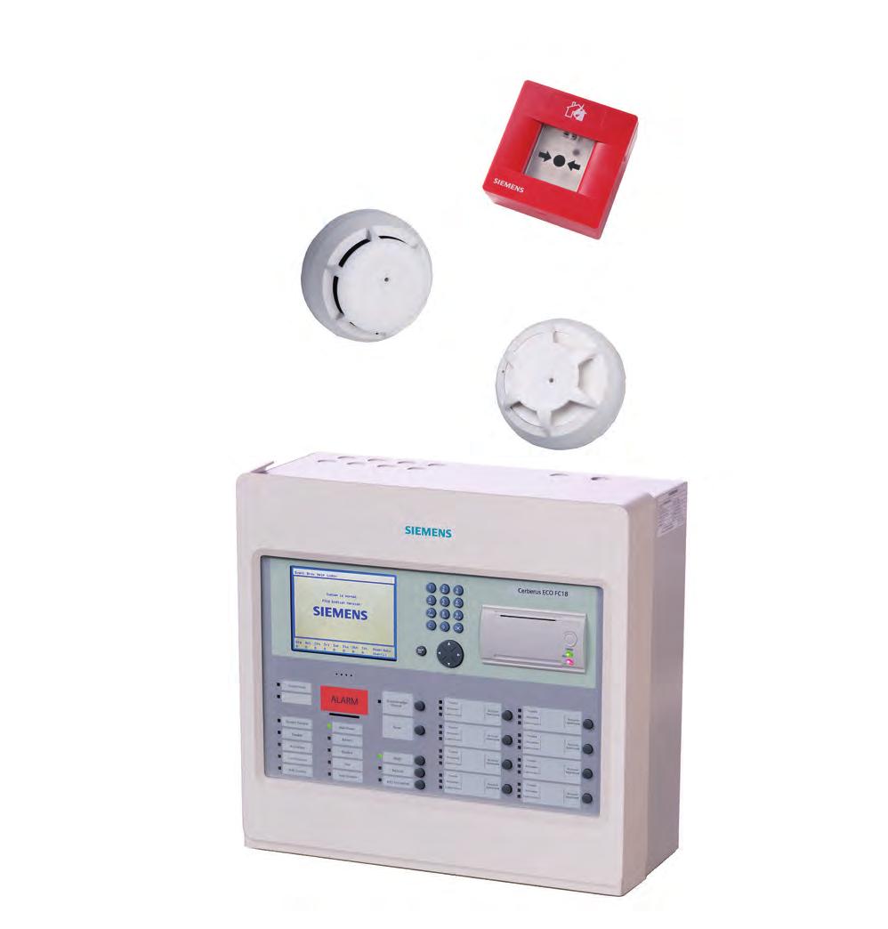

1 2015 NEW Cerberus ECO Fire Safety Products and Accessories Product Catalogue siemens.com/buildingtechnologies
2 Contents Cerberus ECO enjoy protecting 3 FC18 Control Panel Range 4 FD181 device range 5 Cerberus ECO System overview 6 Cerberus ECO at a glance 8 System Load Reference 9 Controller 10 FC1820 / FC1840 Fire Alarm Controller 10 FC1861 / FC1862 / FC1863 Fire Alarm Controller 11 Detectors and other field devices 12 FDO181 Smoke Detector 12 FDO181/FDO181C Dust Cap (Red) 12 FDT181 Heat Detector 13 FDB181 Detector Base 13 FDO181C Collective Smoke Detector 14 FDT181C Collective Heat Detector 14 FDB181C Collective Detector Base 15 FDCAI181 Alarm indicator 16 FDM181 Manual Call Point 17 FDCIO181-1 Input Module 18 FDCIO181-1 Input/Output Module 18 FDCIO181-2 Input/Output Module 19 FDCI181-2 Input Module 20 FDCI183 Collective Input Module 20 FDCL FT1810 Floor Repeater Display 22 Mimic Display Board 22 Spare Parts 26 FCM1811-A1 FC18 CPU Board (For FC1820/40/6x) 23 FCM1820-A1 FC18 Interlocking Board (For FC1820/40/6x) 23 FCI1801-A1 FC18 Card (For FC1820/40) 24 Housing for FC18 Series Module 24 FCI1802-A1 BDS Card for FC18 Controller 25 FCI1802-B1 BDS Card for FC18R Controller 25 FC18 Printer (For FC1820/40/6x) 26 FHA1810-A1 FC18 Housing Front Cover (For FC1820/40) 26 FCM1821-A1 FC18 Terminal Board (For FC1820/40) 26 FCA1804 FC18 USB/RS232 Adapter 27 FC18 Power Supply (5A) (Power supply for FC1820/40) 27 FC18R-FC186x card (For FC186x) 27 FC18R-FC186x Terminal Board of Main board (For FC186x) 28 FC18R-FC186x Terminal Board of Interlocking Panel (For FC186x) 28 FC18R-FC186x Terminal Board of card (For FC186x) 28 FC18R Power Supply (Power supply for FC186x) 28 FC18R-FC186x Main Unit (For FC186x) 28 Order No. Index 29 Appendix 31 Appendix Index 31 System Installation Guidelines 32 Installation and Wiring 41
3 Cerberus ECO enjoy protecting Lives and businesses deserve reliable protection from the risk of fire, and in Siemens Cerberus ECO you can benefit from such protection by the system s exceptionally smart and powerful fire detection product series. Cerberus ECO has specifically been designed with small to medium premises in mind - including commercial buildings, hotels, shopping arcades, residential and a host of similar enterprises. With more than 160 years of Siemens fire safety expertise to draw upon, Cerberus ECO incorporates key state-of-the-art global technologies that are second to none. The products and system adopt simple maintenance and operation design concepts in order to keep installation and commissioning as straightforward as possible. Cerberus ECO delivers dependable fire detection and alarm signalling, while maximising the protection of individuals, buildings and assets. Designed for simple installation, maintenance and operation (SIMO design concept) Tailored for the needs of users in small to medium sized businesses for simple, cost-efficient protection, Cerberus ECO has adopted simple installation, maintenance and operation design concepts for the products and system that take into account the complete working cycle of installers and users. International quality product Cerberus ECO has been specially developed by a dedicated SMART R&D team based in China, a strong centre of competency for SMART products (Simple, Maintenance-friendly, Affordable, Reliable, Timely-to-market). This ECO product series incorporates key state-of-the-art global technologies and system architecture, while complying with Siemens high quality standards. Complete product range - A wide range of applications Cerberus ECO s compact and complete range of cost-efficient fire safety products - tailor-made to protect your staff, buildings and assets - comprises fire detectors as well as control panels and peripheral equipment such as manual call points, and input and output modules. Cerberus ECO is the reliable choice for a wide range of applications whether they are for commercial buildings, hotels, shopping arcades, commercial, residential or similar enterprises. Putting you first - Service is part of the package Siemens recognises that pre-sales and after-sales services are essential for reliable fire detection products, which is why Cerberus ECO comes with a series of valuable service offerings for both installers and users. To support users to effortlessly install and operate the system, Siemens offers a customer hotline, e-training, and quick and reliable logistics. Powerful networking Cerberus ECO installation grows with you. So should you want to extend or convert your building, Cerberus ECO installation can be easily expanded. Free wiring topology Cerberus ECO enables you to achieve higher cost-effectiveness by optimising installation and maintenance costs via free wiring topology. Smart devices - Innovative features Devices in the Cerberus ECO product series are equipped with numerous powerful features for easy installation and commissioning. The dust and dirt compensation feature and Sticker method installation for detectors, 360-degree viewable alarm indicator, PCfree commissioning on panel with large easy-to-read LCD monitor, and easy-touse menu button on panel, are just some of the innovative features of this system. Highlights Reliable product incorporates key state-of-theart global technologies and Siemens high quality standards High cost-effectiveness affordable by small to medium sized businesses Smart design for simple installation, maintenance and operation User-friendly operation expandable and compatible with future developments 3

 with three panel options - FC1820 ( 252 points), FC1840 ( 504 points) and FC186x (504-1,512 points) - are offered in the highly")
4 FC18 Control Panel Range 4 Highlights Highly user-friendly panel range with three panel options. Quick and accurate programming via PC or on panel with large 320 x 240 pixels LCD monitor. Easy-to-use menu button to call out pull-down menu for swift testing, commissioning, configuration, event management, monitoring and report handling. Flexible file handling simplifies commissioning and reduces costs. Easy programming and commissioning enabled by innovative tools and functions. Highly user-friendly panel range A new range of control panels (FC18) with three panel options - FC1820 ( 252 points), FC1840 ( 504 points) and FC186x (504-1,512 points) - are offered in the highly user-friendly Cerberus ECO product series, which makes installation, operation, integration and maintenance easier than ever. Cerberus ECO provides the flexibility you need for system expansion, modernisation and backward-compatibility innovation, and enables you to achieve higher cost-effectiveness by optimising installation and maintenance costs with flexible wiring technology. This new panel stubs on loop as well as star style field bus topology and free polarity wire connection. Each panel can monitor and operate from 252 to 1,512 devices and enables networking with up to 32 panels. Programming - PC or Panel The Cerberus ECO FC18 control panel range supports programming via PC or panel. Equipped with a large 320 x 240 pixels LCD monitor, programming work is rapid and accurate. Easy-to-use - Menu button on panel An easy-to-use menu button is available on the FC18 control panel range. Testing, commissioning, configuration, event management, monitoring and report handling are all easily accomplished by simply pushing the menu button to call out the user-friendly pull-down menu. Flexibility - File handling Cerberus ECO incorporates a series of features to support flexible file handling to reduce commissioning costs: Configuration file can be exported to and imported from Excel file. No re-configuration / re-download of configuration file necessary following firmware version updates. Download & Upload priority enables uninterrupted download and upload process. History record can be uploaded from panel to PC to accommodate Expandable archiving. Customer report file with information on all devices mounted on site can be exported. Easy programming and commissioning Innovative tools and functions to simplify and reduce the time for programming work, such as: Unique ID code for each peripheral enables easy localization and lifecycle identity. Logical expression name to enhance readability. Group programming function to simplify logic relations. Multi-device-select function enables assignment of multiple devices in one group. System copy & paste function for easy merging of configurations by different technicians.


5 FD181 device range Complete range of devices A complete range of devices (FD181) are offered in the Cerberus ECO fire detection product series, including smoke and heat detectors. Dual-channel input module and dual-channel input/output module with open/short circuit monitoring, floor repeat terminal for easy access of alarm information, re-settable manual call point, collective input module, and an isolator module are also provided as part of the comprehensive package. Fast & Accurate fire detection Benefit from Siemens advanced communication protocol from global R&D team, which assures quick identifying of fire dangers and reliable signal transmission. Logical Sticker method installation The detectors are designed for easy commissioning by logical Sticker method installation. Each detector has a unique device ID sticker attached at the back that can be positioned on project drawings for quick and accurate testing and commissioning. Protective caps and dust/dirt compensation Eye-catching protective cap in red is available for the protection of smoke detector during the installation period. Together with a dust/dirt compensation feature, greatly facilitate smoother installation work and reduce costs. Strict enforcement of environmental standard In deference to the environment, all detectors are RoHS compliance. Highlights Advanced communication protocol assures fast & accurate fire detection Complete range of devices with smart designs Logical Sticker method installation via unique device ID sticker Detector protective caps and dust compensation feature facilitate smoother installation and reduce costs 5
6 Cerberus ECO System overview FXS1800 programming tool Graphic Display Equipment Powerful control panels, smart detectors and complete peripheral devices. Cerberus ECO fire detection product series supports powerful networking and provides a smart choice for reliable protection. FC18-FC1820 Fire alarm controller (252 points) Horn / Strobe Horn / Strobe NAC circuit FC18-FC1840 Fire alarm controller (504 points, with BDS line card) FC 18-BUS Controller Network FT1810 Floor Repeater Display FR18-BUS Floor Repeater Display Network NAC circuit Horn / Strobe Horn / Strobe FDO181 Smoke detector BDS221A Output Module FDCIO181-1 I/O module FDCI181-1 Input module FD18-BUS Detection Network FDT181 Heat detector BDS132A Input Module BDS031 Heat Detector FDO181C Collective Smoke detector FDCI181-2 Input module FDM181 Manual Call Point BDS051 Smoke Detector FDT181C Collective Heat detector FDO181 Smoke detector FDCL181 BDS121A Manual Call Point FDCAI181 alarm indicator 6
7 FDO181C Collective Smoke Detector FC18-BUS Controller Network Cerberus ECO FC18 panel range enables interlocking with up to 32 FC18 panels via FC18-BUS. FDCL181 line separator FDO181 Smoke detector FDT181C Collective Heat Detector FDCI183 Collective Input Module FDM181 Manual Call Point FD18-BUS Detection Network Each FC18 panel - FC1820, 1840 or 186X - enables monitoring and operating from 252 to over 1,512 devices via FD18-BUS. This new panel range supports from one loop to eight loops configuration, stub on loop as well as star style field bus topology and free polarity wire connection. FDCL181 line separator FDO181 Smoke detector FDT181 Heat detector FDM181 Manual Call Point FR18-BUS Floor Repeator Display Network A floor repeater display can be connected via FR18-BUS for remote monitoring to further reduce costs. FC18R-FC186x Fire alarm controller (504-1,512 points,with BDS line card) NAC circuit ECO control panels have built-in NAC (Notification Alarm Control) alarm output. It can be directly connected to notification alarm devices such as horn or strobe. FR18-BUS Floor Repeater Display Network FT1810 Floor Repeater Display FTM1811 Mimic Display Board NAC circuit Horn / Strobe Horn / Strobe FDCI181-2 Input module FDCL181 FDO181 Smoke detector FDO181 Smoke detector FDCL181 FD18-BUS Detection FDT181 Heat detector Network FDCI183 Collective Input Module FDCL181 FDO181 Smoke detector FDT181 Heat detector FDCAI181 alarm indicator FDO181 Smoke detector FDM181 Manual Call Point FDCIO181-2 I/O module FDCL181 FDO181 Smoke detector FDT181 Heat detector FDCAI181 alarm indicator 7
8 Cerberus ECO at a glance Control panels Type FC1861 / FC1862 / FC1863 FC1840 FC1820 Description Fire alarm controller Fire alarm controller (504 points) Fire alarm controller (252 points) Features Loop, stub on loop or star style field bus topology, free polarity wire connection, interlocking up to 8 panels, easyto-use menu button, programmable from PC or Panel 2 loops / 4 loops / 6 loops 504 devices / 1,008 devices / 1,512 devices 2 loops, 504 devices 1 loop, 252 devices Detectors Type FDO181 FDT181 FDO181C FDT181C Description Addressable Smoke detector (with protective red cap) Addressable heat detector Collective smoke detector Collective heat detector Features Easy commissioning by Sticker method installation, with dust compensation Easy commissioning by Sticker method installation Collective detector, no address setting, polarity free connection Collective detector, no address setting, polarity free connection Addressable modules Type FDCI183 FDCI181-2 FDCIO181-2 FDCL181 FDCI181-1 FDCIO181-1 Description Collective Input Module Input module I/O module Input module I/O module Features 1 monitored inputs as collective detector connection Dual-channel Input Dual-channel Input/Output - Resettable manual call point Mimic Display Board Floor repeater display Alarm indicator Type FDM181 FTM1811 FT1810 FDCAI181 Description Manual Call Point Mimic Display Board Floor Repeater Display Alarm indicator Features With reset function 60 outputs for LED activation Connected via FR18-BUS for remote monitoring Indicate quickly the source of an alarm signal 8
9 System Load Reference Detectors and other field devices Type Name Load Factor Quiescent current(ma) Max. current(ma) FDO181 Smoke Detector FDT181 Heat Detector FDO181C Collective Smoke Detector FDT181C Collective Heat Detector FDM181 Manual Call Point FDCI181-2 Input Module FDCIO181-2 Input/Output Module FDCL FDCI183 Collective Input Module FDCI181-1 Input module FDCIO181-1 Input/Output module FDCAI181 alarm indicator Floor Panel Type Name Address Quiescent current(ma) Max. current(ma) FT1810 Floor Repeater Display FTM1811 Mimic Display Board Panels Type Name Address FC1820 Fire Alarm Controller ( 252 points) Quiescent current(a) Max. current(a) FC1840 FC1861 FC1862 FC1863 Fire Alarm Controller ( 504 points) Fire Alarm Controller ( 504 points) Fire Alarm Controller ( 1,008 points) Fire Alarm Controller ( 1,512 points)
10 Controller Controller Type FC1820 FC1820 / FC1840 Fire Alarm Controller Order No. S54420-C1-A1 FC1840 Multi-language operation menu designed Windows-like for fast and easy operation Shortcut key (right key) for popping out operation items of equipment/event Large history storage size for up to 10,000 records, first-in-first-out order; all events can be recorded during operation period LCD backlight Auto-off mode. When no operation or message to display within preset time, LCD backlight will automatically turn off. When there are events / operations, LCD will light up automatically to display events and/or interlock devices 2 channels of programmable input/output (Output: 40mA@24VDC can be programmed as general alarm output or general trouble output; Input: dry contact) 1 channel of NAC for audible and visible devices (max. 8 channels of interlocking functions for automatic control and manual operations of control equipment Efficient group programming according to different usage FC1820 controller can connect up to 252 points; FC1840 controller can connect up to 504 points Up to 32 controllers can be networked together Max. distance of controller network bus (FC18-BUS) 1,000m Twisted paired cable for polarity-free detection bus (FD18-BUS); max. loop distance up to 2,500m, and max. stub distance up to 1,500m (wiring capacity from 1.0 to 1.5 mm 2 ) Three user levels for different operation authority. Each user level accessed by pre-defined, changeable password Convenient pluggable terminals with clear marks for field wiring Auto-mapping function supports commissioning task Detection algorithm can be adjusted by controller according to different environment to provide high reliability of alarm report and reduce false alarms Programming either directly from controller or computer Sticker Method for ease of on-site commissioning FD18-BUS detection bus can be configurated as loop or stubs FC18-BUS controller bus can be configurated as stub FC1820 FC1840 No. of line cards 1 2 Number of points LCD screen pixels, backlit No. of programmable input/output on main board 2 No. of zone of interlocking panel 8 No. of NAC 1 Maximum history records 10,000 Max. distance between controllers within FC18-BUS 1,000 m Max. No. of controllers connected within FC18-BUS 32 Max. distance between controller and FRT within FR18-BUS 1,000 m Max. No. of FRT connected to controller 32 Auto-mapping function Operation from terminal Battery (not included) Depends on local regulation Communication interface Special converter module Input voltage 220VAC@1.5A, 110VAC@3A 220VAC/50Hz, 110VAC/60Hz Power supply capacity 5 A@24 VDC External power output 1 A@24 VDC Size (mm) 437Wx 408Hx170D Weight (without battery) kg Power fuse 220VAC@1.5A, 110VAC@3A Battery fuse 24 VDC@5.0 A Operating temperature 0 ~ +40 C Storage temperature 10 ~ +50 C Relative humidity 95% (40±2 C) Protection category IP30 Environment requirement Indoor / Clean A6V S54420-C2-A1 10
 for popping out operation items of equipment/event Large history storage size for up to 10,000 records, first in first out order, all events can be recorded during the operation period LCD")
11 Controller Controller 1 Type FC18R-FC186x FC1861 / FC1862 / FC1863 Fire Alarm Controller Multilanguage operation menu designed with Windows-like style for fast and easy operation Shortcut key (right key) for popping out operation items of equipment/event Large history storage size for up to 10,000 records, first in first out order, all events can be recorded during the operation period LCD backlight Auto-off mode. When there is no operation or message to display within preset time, LCD backlight will be automatically turn off. When there are events / operations, LCD will light up automatically to display events and/or interlock devices 2 channels of programmable input/output (Output: 40mA@24VDC, it can be programmed as general alarm output or general trouble output; Input: dry contact) 1 channel of NAC for audible and visible devices (max. 8 channels of interlocking functions for automatic control and manual operations of control equipments Efficient group programming according to different uses FC1861 controller can support up to 504 points, FC1862 controller can support up to 1,008 points, FC1863 controller can support up to 1,512 points. All the FC18R-FC186x controller can be extended up to 2,016 points by add Cards. Up to 32 controllers can be net worked together Controller network bus (FC18-BUS) has a max. distance of 1,000m Twisted paired cable is for polarity-free detection bus (FD18-BUS), transmission distances is up to 2,500m in loop mode, and 1,500m for a stub line mode (the wiring capacity is between 1.0 to 1.5 mm 2 ) Three user levels for different operation authority. Each user level is accessed by a pre-defined and changeable password Convenient pluggable terminals with clear marks for field wiring Auto-mapping function to support on commissioning task Detection algorithm can be adjusted from controller according to different environment, to provide high reliability of alarm report and reduce false alarm Programming can be done either directly on controller or through computer Sticker Method provide easy for commissioning on site FC1861 FC1862 FC1863 No. of line cards Number of points 504 1,008 1,512 (can extended to 2,016 points) LCD screen pixels, backlit No. of programmable input/output on mainboard 2 No. of zone of interlocking panel 8 No. of NAC 1 Maximum history records 10,000 Max. distance between controllers within FC18-BUS 1,000 m Max. No. of controllers connected within FC18-BUS 32 Max. distance between a controller and a FRT within FR18-BUS 1,000 m Max. No of FRT connected to a controller 32 Auto-mapping function Operation from terminal Battery (not included) Depends on local regulation Communication interface Special converter module Input voltage 220VAC@3A, 110VAC@6A 220VAC/50Hz, 110VAC/60Hz Power supply capacity 10 A@24 VDC Size (mm) 1000 H 600 W 200 D Weight (without battery) 33.5 Kg Power fuse 220VAC@3A, 110VAC@6A Battery fuse 24VDC@10A Operating temperature 0 ~ +40 C Storage temperature 10 ~ +50 C Relative humidity 95% (40±2 C) Environment requirement Indoor / Clean A6V Order No. S54420-C5-A1 S54420-C6-A1 S54420-C7-A1 11
12 Detectors and other field devices Detectors and Base Type FDO181 FDO181 Smoke Detector Order No. S54320-F2-A1 The FDO181 wide-spectrum smoke detector is an optical smoke detector with an optical sensor. It works according to the principle of forward scattering. The detector reacts extremely sensitively to light aerosols caused by fire. The increased sensitivity makes possible the early detection of smouldering and open fires. With built-in CPU, signals received are processed by intelligent algorithm Two kinds of sensitivity settings (standard, sensitive) Opto-electronic sampling chamber more reliably and accurately detects fire Automatically addresses setting without encoder setting or DIP switch For early detection of smoke and smouldering fires Resistant to environment and interference factors such as dust, fibres, insects, humidity, extreme temperatures, electro-magnetic interference, corrosion, vapour, vibration, synthetic aerosols and atypical fire phenomena All-around visible alarm indicator Communication via FD18-BUS, polarity-free connection Sticker Method for ease of commissioning Operating voltage VDC Operating current (quiescent) 0.26 ma Activation current 1.2 ma Sensitivity Standard 2.5% Sensitive1.8% Operating temperature C Storage temperature C Relative humidity 96% (40±2 C) Communication protocol FD18-BUS Load factor 1 Colour White, RAL 9010 Protection category GB IP44 A6V FDO181_DC FDO181/FDO181C Dust Cap (Red) Protects the FDO181 smoke detector and FDO181C collective smoke detector during the installation. (Please remove the dust cap after installation!) 12


13 Detectors and other field devices Detectors and Base 2 Type FDT181 FDT181 Heat Detector Order No. S54320-F3-A1 Heat detector FDT181 is an intelligent detector. It is used for early fire detection inside a building. With built-in CPU, signals received are processed by intelligent algorithm Two operation modes: A2S/A2R Automatically addresses setting without encoder setting or DIP switch All-around visible alarm indicator Resistant to environment and interference factors such as humidity, electro-magnetic interference, corrosion and vibration. Communication via FD18-BUS, polarity-free connection Sticker Method for ease of commissioning Operating voltage VDC Operating current (quiescent) 0.26 ma Activation current 1.2 ma Operating temperature C Storage temperature C Relative humidity 96% (40±2 C) Communication protocol FD18-BUS Load factor 1 Colour White, RAL 9010 Protection category GB IP44 A6V FDB181 FDB181 Detector Base S54320-F1-A1 The FDB181 detector base is a universal base. It is fixed on the fire detection site and used for the installation of FD181 series detectors: FDO181 Smoke detector FDT181 Heat detector Universal bases, applicable to both surface install and conceal install Large opening in the detector base for easy cable insertion Adopt environmentally friendly materials Connection terminals mm 2 Operating temperature According to Storage temperature data of Protection category GB detectors Colour White, RAL 9010 A6V


14 Detectors and other field devices Detector and Base Type FDO181C FDO181C Collective Smoke Detector Order No. S54320-F11-A2 The FDO181C is an optical smoke detector with an optical sensor. It works according to the principle of forward scattering. The detector reacts extremely sensitive on light aerosols caused by fire. The increased sensitivity makes the detection of smoldering and open fire possible. Intelligent detector with built-in CPU, providing advanced distributed intelligence for optimum reliable detection principle Opto-electronic sampling chamber detects fire more reliable and accurate Collective detector, no address setting, polarity free connection Communication with FC18 controller via FDCI183 collective input module, each FDCI183 can connect max. 32 collective detectors Particularly suited for the early detection of smoke-generating flaming and smoldering fires Resistant to environment and interference factors such as dust, fibers, insects, humidity, extreme temperatures, corrosive, vapors, vibration, synthetic aerosols. With immunity against electro-magnetic interference Self-test of operating status, when fault occurs or low voltage happens, indicator can prompt user Automatic drift compensation and dust prompt for reducing false alarm because of dust accumulation 360 visible alarm indicator Dust cap protects the detector from being contaminated by construction work Operating voltage VDC Operating current (quiescent) 0.1 ma Activation current 60.0 ma Sensitivity Standard 2.4%m Operating temperature C Storage temperature C Relative humidity 96% (40±2 C) Colour White, RAL 9010 Protection category GB IP40 A6V FDT181C FDT181C Collective Heat Detector The heat detector FDT181C is a collective detector. It is used for fire detection inside a building. Operation modes: A2 Collective detector, no address setting, polarity free connection Communication with FC18 controller via FDCI183 collective input module, each FDCI183 can connect max. 32 collective detectors 360 visible alarm indicator Resistant to environment and interference factors such as humidity, corrosive and vibration, with immunity against electro-magnetic interference. Operating voltage VDC Operating current (quiescent) 0.1 ma Activation current 60.0 ma Operating temperature C Storage temperature C Relative humidity 96% (40±2 C) Colour White, RAL 9010 Protection category GB IP40 S54320-F12-A2 A6V


15 Detectors and other field devices Detector and Base 2 Type FDB181C FDB181C Collective Detector Base Order No. S54320-F9-A2 The FDB181C collective detector bases are universal bases. It s fixed on fire detection site and are used for installations of FD181C series collective detectors: FDO181C collective smoke detector FDT181C collective heat detector Universal bases, applicable to both surface install and conceal install Large opening in the detector base for easy cable insertion Adopt environmentally friendly materials Connecting terminals mm 2 Operating temperature According to Storage temperature data of Protection category GB detectors Colour White, RAL 9010 A6V

16 Detectors and other field devices Alarm Indicator Type Order No. FDCAI181 FDCAI181 Alarm indicator The FDCAI181 alarm indicator is connected to the loop and can be programmed to indicate quickly the source of an alarm signal from detectors which are not easily accessible or visible. Addressing and control takes place via the control panel. The alarm indicator is switched as if it was a detector in the detector line. The alarm indicator has 2x2 connectors for the detector line. The alarm indicator contains indicator lamps (LEDs). They light up as soon as the connected fire detector gives an alarm. S54370-F21-A1 Addressable external alarm indicator Indication of detectors in alarm in ceiling voids etc. Free programmable Communication via FD18-BUS (individual addressing) Modern flat design Non screw terminals Ecologically processing Recyclable materials Electronic and synthetic materials easily separable Operating voltage Operating current (quiescent) Blinking cycle DC V <200µA 1s: Locate or Alarm 0.5s: Locate when Alarm Load factor 1 Connection terminals mm 2 Operating temperature C Storage temperature C Humidity 95 % rel Communication protocol FD18-BUS Color white, ~RAL 9010 Protection category IP40 A6V

17 Detectors and other field devices Resettable Manual Call Point 2 Type FDM181 FDM181 Manual Call Point Order No. S54321-F1-A1 The manual call point serves for the manual activation of alarms in case of fire. It consists of a housing and an electronic component. Resettable operation panel Automatically address setting without encoder setting or Dip-switch Indicates condition (Alarm or Locate) by means of an LED Communication via FD18-BUS Sticker Method for ease of commissioning Operating voltage VDC Operating current (quiescent) 0.22 ma Activation current 1.2 ma Operating temperature C Storage temperature C Relative humidity 95% Communication protocol FD18-BUS Load factors 1 Connection terminals mm 2 Colour Red, RAL3000 Protection category GB IP44 A6V
18 Detectors and other field devices Module and Fire Repeater Display Type FDCIO181-1 FDCIO181-1 FDCIO181-1 Input Module 1 monitored digital input Input lines are monitored for open line and short/open circuit (terminal resistors is man-datory) Microprocessor-controlled signal evaluation Prevention of noise interference through intelligent analysis of input signals LED display of input status Automatic address setting, without encoder settings or Dip-switch Power supply via FD18-BUS Communication with controller via FD18-BUS(detection line) Directly used in dry areas, Applicable in dusty and humid areas when installed in FDCH221 housing Sticker Method easy for commissioning Operating voltage VDC Operating current(quiescent) 0.27 ma Activation current 0.37 ma Monitoring resistors 3.3KΩ(1/4w) / 680Ω(1/4w) Operating temperature C Storage temperature C Humidity 95 % Communication protocol FD18-BUS Load factors 3 Connection terminals mm 2 Color - Housing white, RAL Cover transparent Protection category EN60529/IEC529/GB With housing FDCH221 IP65 A6V FDCIO181-1 Input/Output Module Microprocessor-controlled signal evaluation Automatic address setting, without encoder settings or DIP switch 1 monitored input, 1 monitored output LED display of input and output status Input lines monitored for open line or short/open circuit Prevention of noise interference through intelligent analysis of input signals Output lines monitored for open line or short/open circuit (when potential output not acti-vated) Output monitoring configurable(on/off) Control output for equipment 24 VDC, max. 2 A Communication with controller via FD18-BUS(detector line) Directly used in dry areas. Applicable in dusty and humid areas when installed in FDCH221 housing Sticker Method easy for commissioning Operating voltage VDC Operating current (quiescent) 0.31 ma Activation current 0.51 ma Output - Capacity 2 24 VDC - Monitoring resistor 3.3k Ω(1/4w) - Diode 1N5404 Input - Monitoring resistor 3.3k Ω / 680 Ω Operating temperature C Storage temperature C Humidity 95 % rel. Communication protocol FD18-BUS Load factors 3 Connection terminals mm 2 Color - Housing white, RAL Cover transparent Protection category EN60529/IEC529/GB With FDCH221 housing IP65 A6V Order No. S54322-F7-A1 S54322-F8-A1 18
")
19 Detectors and other field devices Module and Fire Repeater Display 2 Type FDCIO181-2 FDCIO181-2 Input/Output Module Microprocessor-controlled signal evaluation Automatic address setting, without encoder settings or DIP switch 2 monitored inputs, 2 monitored outputs LED display of input and output status Input lines monitored for open line or short/ open ciruit(terminal resistors mandatory) Prevention of noise interference via intelligent analysis of input signals Output lines monitored for open line or short/open circuit (when potential output not activated) Output monitoring configurable(on/off) Control output for equipment 24 VDC, max. 2 A Communication with controller via FD18-BUS(detector line) Directly used in dry areas. Applicable in dusty and humid areas when installed in FDCH221 housing Sticker Method for ease of commissioning Operating voltage VDC Operating current (quiescent) 0.56 ma Activation current 0.85 ma Output - Capacity 2 24 VDC - Monitoring resistor 3.3k Ω (1/4w) - Diode 1N5404 Input - Monitoring resistor 3.3k Ω(1/4w) / 680 Ω(1/4w) Operating temperature C Storage temperature C Relative humidity 95 % Communication protocol FD18-BUS Load factors 5 Connection terminals mm 2 Colour - Housing white, RAL Cover transparent Protection category EN60529 / IEC529/GB With FDCH221 housing IP65 A6V Order No. S54322-F2-A1 19
 Microprocessor-controlled signal evaluation Prevention of noise interference via intelligent analysis of input signals LED display of input status Automatic address")
 0.")
20 Detectors and other field devices Module and Fire Repeater Display Type FDCI181-2 FDCI181-2 Input Module 2 monitored digital inputs Input lines are monitored for open line or short/open circuit (terminal resistors mandatory) Microprocessor-controlled signal evaluation Prevention of noise interference via intelligent analysis of input signals LED display of input status Automatic address setting, without encoder settings or Dip-switch Power supply via FD18-BUS Communication with controller via FD18-BUS (detection line) Directly used in dry areas. Applicable in dusty and humid areas when installed in FDCH221 housing Sticker Method for ease of commissioning Operating voltage VDC Operating current (quiescent) 0.33 ma Activation current 0.45 ma Monitoring resistors 3.3k Ω (1/4w) / 680Ω(1/4w) Operating temperature C Storage temperature C Relative humidity 95 % Communication protocol FD18-BUS Load factors 3 Connection terminals mm 2 Colour - Housing white, RAL Cover transparent Protection category EN60529 / IEC529/GB With FDCH221 housing IP65 A6V Order No. S54322-F1-A1 FDCI183 FDCI183 Collective Input Module 1 monitored input as collective detector connection LED display of alarm and fault status External 24VDC power required Microprocessor-controlled signal evaluation Earth fault monitoring With the Zener diode barrier, it is also possible to connect intrinsically safe detectors Directly used in dry areas.applicable in dusty and humid areas when installed in FDCH221 housing Sticker Method for ease of commissioning FD18-BUS Operating voltage VDC FD18-BUS Operating current Quiescent: 0.45mA Alarm:1.1mA External power supply - Input voltage A End of line 1.5KE20CA(EOL) or EOL22(ex) Operating temperature C Storage temperature C Relative humidity 95 % Communication protocol FD18-BUS Local factors 3 Connection terminals mm 2 Color - Housing Pure white, RAL Cover transparen Protection category EN60529 / IEC529 - with FDCH221 housing IP65 impedance of collective detection line <150Ω (twins cable) A6V S54312-F8-A2 20

21 Detectors and other field devices Module and Fire Repeater Display 2 Type FDCL181 FDCL181 FDCL181 is used to detect and isolate the short-circuit part of the FD18-BUS. It s also connected to prevent different branches from breaking down at the same time due to short circuit. Protection of FD18-BUS from short-circuit For T branches of FD18-BUS Indicates conditions by LED indicator Automatic address setting without encoder settings or Dip-switch Communication via FD18-BUS (separate address) Directly applicable in dry areas. Applicable in humid and dusty areas with FDCH221 housing Sticker Method for ease of commissioning Operating voltage VDC Operating current (quiescent) 0.25 ma Activation current 0.45 ma Operating temperature C Storage temperature C Relative humidity 95% Communication protocol FD18-BUS Load factors 1 Connection terminals mm 2 Colour - Housing white, RAL Cover transparent Protection category EN60529 / IEC529/GB With FDCH221 housing IP65 A6V Order No. S54322-F3-A1 21

 External 24VDC power required In total, up to 32 floor repeater displays can be connected to one FC18 fire")
22 Detectors and other field devices Module and Fire Repeater Display Type Order No. FT1810 FT1810 Floor Repeater Display The floor repeater display is an indication and operation unit in a fire detection system with following functions: Indication of events Operation Alarm Scrolling through lists Trouble Switch off buzzer Small floor repeater operating and display panels for use with the addressed FC18 fire detection system Large backlight LCD display(192x64 pixels) whose contrast can be set manually Communication with controller via FR18-BUS (individual address) External 24VDC power required In total, up to 32 floor repeater displays can be connected to one FC18 fire alarm controller Flat, elegant housing Operating voltage 24 VDC±20% Operating current (quiescent) 30 ma Activation current 110 ma Operating temperature C Storage temperature C Relative humidity 95 % Communication protocol FR18-BUS Connection terminals mm 2 Colour white, RAL 9010 Protection category GB IP30 S54420-F3-A1 A6V FTM1811 Mimic Display Board 60 outputs for LED activation 1 dry contact output for buzzer 2 inputs for Buzzer silence and Lamp test Communication with controller via FR18-BUS(CAN-Bus) (individual address) External 24VDC power required Input/output are not monitored Operating voltage 24 VDC±30% Operating current (quiescent) 100 ma Max. current 200 ma Rated output per LED 10 ma Max. current per LED 15 ma Operating temperature C Storage temperature C Relative humidity 95 % Communication Protocol FR18-BUS Connection terminals mm 2 S54420-F4-A1 A6V
23 Detectors and other field devices Cerberus ECO Controller Spare Parts 2 Type Order No. FCM1811-A1 FCM1811-A1 FC18 CPU Board (For FC1820/40/6x) CPU board together with main board comprises main part of FC1820/40/6x controller. Integration of some common components makes it more general. Mainly used for storing and loading configuration files. S54420-A12-A1 A6V FCM1820-A1 FCM1820-A1 FC18 Interlocking Board (For FC1820/40/6x) S54420-A13-A1 FCM1820-A1 interlocking panel mainly used for auto-control and manual control of important devices (such as fire-pump, fan, etc.) FCM1820-A1interlocking panel has 8 outputs, rated 24VDC/ 40mA, use to activate extinguishing devices on-site; 8 dry contact inputs, used to receive confirmation of activated devices A6V
 S54420-A9-A1 FCI1801-A1 line card specially designed for FC1820/40 series controllers, can automatically identify controllers.")
24 Detectors and other field devices Cerberus ECO Controller Spare Parts Type Order No. FCI1801-A1 FCI1801-A1 FC18 Card (For FC1820/40) S54420-A9-A1 FCI1801-A1 line card specially designed for FC1820/40 series controllers, can automatically identify controllers. Used for connection with FD181 series field devices FCI1801-A 1 line card contains 1 loop or 2 stubs, can connect 252 points FCI1801-A 1 line card applies 2-wire polarity-free detection bus; stub wiring for field bus and free branch acceptable Overload protection available When short line occurs, will activate line protection application automatically. When trouble resolved, line card recovers automatically A6V FDCH221 Housing for FC18 Series Module Housing with seal for the mounting of FC18 series module The required screwed cable glands and back nuts M20 are not included S54312-F3-A1 Dimensions (W x H x D) 207 x 119 x 48 mm Color white RAL 9010 / transparent matt Protection category IP65 24
25 Detectors and other field devices Cerberus ECO Controller Spare Parts 2 Type Order No. FCI1802-A1 FCI1802-A1 BDS Card for FC18 Controller FCI1802-A1 line card is specially designed for FC18 series controllers. It can be automatically identified by controller. It is used for connection with BC80 series field devices. FCI1802-A1 line card contains two lines and each line can connect 127 points. Compatible with BC80en, BC80-UL, FD180 series field deviecs. Compatible with BDS331 floor repeater display. 2-wire polarity-free of detection bus, stub wring is available and free branch is acceptable. Operating voltage +28 V Quiescent current 650 ma / 24 V Max. current 1.1 A / 24 V Operating temperature 0 ~ +40 ºC Storage temperature -10 ~ +50 ºC Humidity 95% (40±2 ºC) Size 110*120 mm Max. No. of line 2 Max. No. of field devices per line 127 Wire type for FD18-BUS Recommend RVS1.0 ~ RVS1.5 impedance 20 Ω Short circuit auto protection (isolation) available A6V S54420-A25-A1 FCI1802-B1 FCI1802-B1 BDS Card for FC18R Controller FCI1802-B1 line card is specially designed for FC18R series controllers. It can be automatically identified by controller. It is used for connection with BC80 series field devices. FCI1802-B1 line card contains two lines and each line can connect 127 points. Compatible with BC80en, BC80-UL, FD180 series field devices. Compatible with BDS331 floor repeater display. 2-wire polarity-free of detection bus, stub wring is available and free branch is acceptable. operating voltage +28 V Quiescent current 650 ma / 24 V Max. current 1.1 A / 24 V Operating temperature 0 ~ +40 ºC Storage temperature -10 ~ +50 ºC Humidity 95% (40±2 ºC) Size 155*120mm Max. No. of line for each card 2 Max. No. of field devices for each line 127 Wire type for FD18-BUS Recommend RVS1.0~RVS1.5 impedance 20 Ω Short circuit auto protection (isolation) available A6V S54420-A26-A1 25
 S54420-C18-A1")


26 Spare Parts Cerberus ECO Controller Spare Parts Type Order No. FCP1810-A2 FC18 Printer (For FC1820/40/6x) S54420-C18-A1 Printer can print out history event or on real time FHA1810-A1 FHA1810-A1 FC18 Housing Front Cover (For FC1820/40) S54420-B19-A1 For cover of FC1820/40 fire alarm controller A6V FCM1821-A1 FCM1821-A1 FC18 Terminal Board (For FC1820/40) S54420-A14-A1 FCM1821-A1 terminal board specially designed for FC18 series controllers; easy for connection A6V
 (Power supply for")
 S54420-A10-A1 FCI1802-A2 line card is specially designed for FC186x controllers, can automatically identify")

27 Spare Parts Cerberus ECO Controller Spare Parts 2 Type Order No. FCA1804 FCA1804 FC18 USB/RS232 Adapter S54420-F8-A1 For downloading and uploading firmware and configuration file FP1802-A2 FC18 Power Supply (5A) (Power supply for FC1820/40) S54420-C21-A1 Input voltage 220VAC/50Hz, 110VAC/60Hz Output voltage 5 A@24 VDC Operating temperature -20 ~ +55 C Storage temperature -45 ~ +85 C Relative Humidity 95% FCI1802-A2 FC18R-FC186x card (For FC186x) S54420-A10-A1 FCI1802-A2 line card is specially designed for FC186x controllers, can automatically identify controllers. It is used for connection with FD18 field devices FCI1802-A2 line card contains 1 loop or 2 stubs, and each line can connect 252 points FCI1802-A2 line card apply 2-wire polarity-free detection bus, stub wiring for field bus and free branch is acceptable Overload protection is available When short line occurs, it will activate the line protection application automatically. When trouble is resolved, line card can recover normal automatically A6V

 S54420-A17-A1 FCM1823-A2 FC18R-FC186x terminal board of card is specially designed for FC18R card, easy for connection A6V10322581 FP1801-A2 FC18R Power Supply (Power supply for")
 S54420-C11-A1 Main unit for FC186x Include CPU board, main board, interlocking panel, LCD and keypad Used for data collection and analysis, and control the field")
28 Detectors and other field devices Cerberus ECO Controller Spare Parts Type FCM1821-A2 FC18R-FC186x Terminal Board of Main board (For FC186x) Order No. S54420-A15-A1 FC18R-FC186x terminal board of Main board is specially designed for FC18R Main board, easy for connection A6V FCM1822-A2 FC18R-FC186x Terminal Board of Interlocking Panel (For FC186x) S54420-A16-A1 FC18R-FC186x terminal board of Interlocking Panel is specially designed for FC18R interlocking panel, easy for connection A6V FCM1823-A2 FC18R-FC186x Terminal Board of card (For FC186x) S54420-A17-A1 FCM1823-A2 FC18R-FC186x terminal board of card is specially designed for FC18R card, easy for connection A6V FP1801-A2 FC18R Power Supply (Power supply for FC186x) S54420-C20-A1 Input voltage 220VAC/50Hz, 110VAC/60Hz Output voltage 10 VDC Operating temperature -20 ~ +55 C Storage temperature 45 ~ +85 C Relative Humidity 95% A6V FCM1801-A2 FC18R-FC186x Main Unit (For FC186x) S54420-C11-A1 Main unit for FC186x Include CPU board, main board, interlocking panel, LCD and keypad Used for data collection and analysis, and control the field device FCM1801-A2 FC18R-FC186x Main unit is used for operation, programming and display all kinds of events on LCD or front panel A6V
29 Type Name Order No. Page FC1820 Fire Alarm Controller (252 points) S54420-C1-A1 10 FC1840 Fire Alarm Controller (504 points) S54420-C2-A1 10 FC1861 (504) S54420-C5-A1 FC1862 (1,008) Fire Alarm Controller S54420-C6-A1 11 FC1863 (1,512) S54420-C7-A1 FDO181 Smoke Detector S54320-F2-A1 12 FDT181 Heat Detector S54320-F3-A1 13 FDB181 Detector Base S54320-F1-A1 13 FDO181C Collective Smoke Detector S54320-F11-A2 14 FDT181C Collective Heat Detector S54320-F12-A2 14 FDB181C Collective Detector Base S54320-F9-A2 15 FDCAI181 Alarm Indicator S54370-F21-A1 15 FDM181 Manual Call Point S54321-F1-A1 16 FDCIO181-1 Input Module S54322-F7-A1 17 FDCIO181-1 Input/Output Module S54322-F8-A1 17 FDCIO181-2 Input/Output Module S54322-F2-A1 18 FDCI181-2 Input Module S54322-F1-A1 19 FDCI183 Collective Input Module S54312-F8-A2 19 FDCL181 S54322-F3-A1 20 FT1810 Floor Repeater Display S54420-F3-A1 21 FTM1811 Mimic Display Board S54420-F4-A1 21 FCM1811-A1 FC18 CPU Board S54420-A12-A1 22 FCM1820-A1 FC18 Interlocking Board S54420-A13-A1 22 FCI1801-A1 FC18 Card S54420-A9-A1 22 FDCH221 Housing for FC18 Series Module S54312-F3-A1 22 FCI1802-A1 BDS Card for FC18 Controller S54312-F3-A1 23 FCI1802-B1 BDS Card for FC18R Controller S54420-A25-A1 23 FCP1810-A2 FC18 Printer S54420-C18-A1 24 FHA1810-A1 FC18 Front Cover S54420-B19-A1 24 FCM1821-A1 FC18 Terminal Board S54420-A14-A1 24 FCA1804 FCA1804 FC18 USB/RS232 Adapter S54420-F8-A1 24 FP1802-A2 FC18 Power Supply (5A) S54420-C21-A1 24 FCI1802-A2 FC18R-FC186x card S54420-A10-A1 24 FCM1821-A2 FC18R-FC186x Terminal Board of Main board S54420-A15-A1 25 FCM1822-A2 FC18R-FC186x Terminal Board of Interlocking panel S54420-A16-A1 25 FCM1823-A2 FC18R-FC186x Terminal Board of Card S54420-A17-A1 25 FP1801-A2 FC18R Power Supply S54420-C20-A1 25 FCM1801-A2 FC18R-FC186x Main Unit S54420-C11-A


30 Cerberus ECO Fire Safety Products and Accessories Product Catalogue - Appendix
31 Appendix Index System Installation Guidelines 28 System Design Guidelines FC18-BUS FS18-BUS Controller Network Single controller capacity FC18/FC18R Controller Input/output wiring diagram FC18/FC18R Interlocking panel wiring diagram FC18/FC18R alarm device (NAC) wiring diagram System Wiring FR18-BUS FR18-BUS Floor Repeater Display (FRT) wiring diagram FD18-BUS FD18-BUS card diagram FD18-BUS Detection loop topology Loop Topology Stub Topology Stub on loop topology application A application B application C application D application E application F 37 Installation and Wiring FDB181/FDB183 Detector Base Installation FDB181C Collective Detector Base Installation FDCAI181 Addressable Alarm Indicator Installation FDCL181 Installation FDCI181-2 Input Module Installation FDCIO181-2 Input/Output Module Installation FDCI183 Collective Input Module Installation FDM181 Manual Call Point Installation FT1810 Floor Repeater Display Installation FTM1811 Mimic Display Board Installation FT1810 Floor Repeater Display Installation FTM1811 Mimic Display Board Installation 48 31
32 Cerberus ECO System Installation Guidelines Heat detector<10m Smoke detector<15m 0.5m < x < 6m 0.5m < x < 6m In this section, we illustrate best practice for installation of fire detection equipment. While not all possible cases may be covered, these are intended to provide guidelines. Local regulations may be more detailed and must always be observed. Please contact your local Siemens sales organization for more detailed information and documentation. Detectors should be positioned* 1.3~1.5m at least 0.5 m from the wall max. 12 m from the previous detector Manual call points manual call points should be positioned* in a clearly visible location 1.5 m from floor level >1m Fire control panels mounting the fire control panel* Keep a minimum distance to objects which could obscure the panel or the view to it 1.3~1.5m Detector positioning near elevators* > 1.5m > 1.5m > 0.5m 32
33 Cerberus ECO System Installation Guidelines Detector positioning near fresh air supply* > 1.5m Use a support to install a detector at ceiling height* Place the detector at the highest point in the room* 33
34 Cerberus ECO System Installation Guidelines Ensure the correct distance to ceiling obstacles* > 0.5m Position the detector within the top 10% of a space* 10%=0.08m > 0.8m Ensure a minimum distance to objects which could obstruct the view to a manual call point* > 0.1m Manual call points should not be obscured by an open door* * Note: or observe local regulations 34
35 Cerberus ECO System Design Guidelines 1.1 FC18-BUS Communication between controllers (CAN-BUS communication). Twisted-pair is required, the maximum length is 1,000m. 1.2 FC18-BUS Controller Network Cerberus ECO system enables max. connection of 32 Cerberus ECO controllers. Each controller can be configured to monitor and control all connected field devices within entire network. Interlocking controls can be programmed within the same controller or across other controllers. For FC18-Bus network will need to set the EOL through dip switch for the first and last controller. ** ** R=120Ω R=120Ω FCH FCL FCH FCL FCH FCL ** Through dip switch setting FC18-Bus FC18-Bus FC18-Bus FT1810/ FTM1811 Floor Repeat Display FR18-Bus CAN + CAN - FTH FTL FC18 FC1820 Controller FC18 FC1840 Controller FC18R FC186x Controller.. 32Controllers FCI1801 Card FCI1801 Card FCI1802 Card FD18-BUS FD18-BUS FD18-BUS Loop or Stub Loop or Stub Loop or Stub 1.3 Single controller capacity Name Type Build-in card Max. line card Max. loop Max. Points FC18-FC1820 Fire alarm controller FC18-FC FC18-FC1840 Fire alarm controller FC18-FC FC18R-FC1861 Fire alarm controller FC18R-FC *6 *6 504 FC18R-FC1862 Fire alarm controller FC18R-FC *6 *6 1,008 FC18R-FC1863 Fire alarm controller FC18R-FC *6 *6 1,512 * CPU can handle 8 line cards 35
36 Cerberus ECO System Design Guidelines 1.4 FC18/FC18R Controller Input/output wiring diagram Note: the load range of each output is 24VDC, 600Ω 1.2kΩ FC18 To Input/Output IO-EOL-FC18 Red Orange Dry Contact Black Black Output Input 1.5 FC18/FC18R Interlocking panel wiring diagram Note: the load range of each output is 24VDC, 600Ω 1.2kΩ IO-EOL-FC18 FC18 To Int. Chan. 1 Red Orange Dry Contact Black Black Output(40mA@24VDC) 1.6 FC18/FC18R alarm device (NAC) wiring diagram FC18 To NAC NAC-EOL-FC18 Red Orange Black Black Visible and audible device 36
37 Cerberus ECO System Design Guidelines 1.7 System Wiring Below shows the loop that Cerberus ECO FC18/FC18R controllers connect with a line card FCI FR18-BUS Communication between FT1810 floor repeater display and FC18 controllers (CAN-BUS conmmunication). The maximum length is 1,000m. 2.2 FR18-BUS Floor Repeater Display (FRT) wiring diagram Note: Ensure positive and negative connections properly in place, FC18-Bus polarity-sensitive. FR18-BUS network will need to install end of line resistor (120Ω) at both ends (EOL setting via dip-switch or jumper). FC18/FC18R 32 FRT To FRT FT1810/ FTM1811 FT1810/ FTM1811 ** ** ** Through Jumper ** Through Jumper 3.1 FD18-BUS Communication between line cards and field devices. The wiring length should less than 1,500m for stub structure and 2,500m for loop structure. 3.2 FD18-BUS card diagram Note: In loop mode, wires from BP1 must end at AP1; wires from BS1 must end at AS1. Connection of field devices polarity-free. To 1 To Field device To Field device 37
38 Cerberus ECO System Design Guidelines 3.3 FD18-BUS Detection loop topology Detection loop topology for FS18 fire alarm control system: Loop Topology Less than 252 points Loop Topology Stub Topology Less than 252 points Stub Topology Stub on loop topology Less than 252 points Stub on Loop Topology 38
39 Cerberus ECO System Design Guidelines application A Maximum 32 FD181 field devices can be connected to line separator or between two line separator. One node cannot be connected by three or more line separators in the same detection line. (The topologies of Fig to Fig are not supported). The line resistance between the controller and the nearest line separator or between two line separators shall be less than 17.5Ω, otherwise line separators are not guaranteed to work normally. Panel FC18 Less than 32 devices between 2 Iine separators application B Panel FC18 Less than 32 devices between 2 s application C Panel FC18 Panel FC18 39
40 Cerberus ECO System Design Guidelines application D Panel FC application E Panel FC application F Panel FC18 40
41 Cerberus ECO Installation and Wiring 4.1 FDB181/FDB183 Detector Base Installation The installation of a base should strictly follow the engineering design drawings, with bases should be evenly distributed. Procedure of installation: 1. Insert the cables through the base and connect them to the terminals. 2. Fix the base to the ceiling with screws. Note: The detector should be installed once construction has been finished. In order to ensure the reliability of the connection between the base and the detector, please do not use U-type terminals. Twisted-pairs with the wiring requirement of 1.0~1.5mm 2 are recommended. P To controller S FDB181/FDB183 Base 5 1a 6 1b P To next base Terminal resistor is not necessary S 4.2 FDB181C Collective Detector Base Installation The installation of a base should strictly follow the engineering design drawings. The bases should be evenly distributed. Connect to FDCI183 collective input module Procedure of installation: 1. Insert the cables through the base and connect them to the terminals. 2. Fix the base to the ceiling with screws. Note: The detector should be installed after the construction has been finished. In order to ensure the reliability of the connection between the base and the detector, please do not use U-type terminals. Twisted-pairs with the wiring requirement of 1.0~1.5mm 2 are recommended. 41


 on a wall or recessmounted socket using 2 4 screws with max. diameter 3 mm.")
. 4. Refit the white cover cap. 5. Snap the white cover cap into place.")

. 2.")

.")
42 Cerberus ECO Installation and Wiring 4.3 FDCAI181 Addressable Alarm Indicator Installation Fig. 1 Fig. 2 Fig. 3 Fig. 4 S S P P Fig. 5 WARNING Electrical voltage on lines Mortal danger due to electric shock During mounting and installation work, voltage must not be applied to the cables. Installation of FDCAI181: 1. Remove the white cover cap (press the black cam). 2. Mount the base plate (Fig. 2) on a wall or recessmounted socket using 2 4 screws with max. diameter 3 mm. 3. Connect the alarm indicator in accordance with the connection diagram (Fig. 5). 4. Refit the white cover cap. 5. Snap the white cover cap into place. Installation of additional frame AI330: For surface-mounted cable entry the additional frame AI330 must also be mounted. Max. cable diameter: 10 mm 1. Mount the additional frame AI330 (accessory) on a wall or recess-mounted socket using two screws with max. diameter of 4 mm (Fig. 3, Fig. 4). 2. Remove the white cover cap from alarm indicator FDCAI181 (press the black cam). 3. Attach the base plate of the alarm indicator to additional frame AI330 with 2 wood or sheet-metal screws of di-ameter 3 mm, max. 16 mm long. 4. Connect the alarm indicator in accordance with the connection diagram (Fig. 5). 5. Refit the white cover cap. 6. Snap the white cover cap into place. FDCAI181 AI330 Details for ordering Type Part No. Designation Weight FDCAI181 S54370-F21-A1 Addressable alarm indicator kg 42
43 Cerberus ECO Installation and Wiring 4.4 FDCL181 Installation Fig Fig FDCL181 Terminal A/B Fig A P S P S Loop line Stub line B P S P S Loop line Stub line Fig Preparation Installation of module in FDCH221 Determine the type of installation: there are 2 types of installation for FDCL181 line separator: - Installation outside a switching cabinet or a control unit: use FDCH221 housing (Fig ). - Installation directly in a switching cabinet or a control unit: mount the module on an even surface (Fig.4.3.1). Damage by water! In humid or wet environments always use the housing FDCH221! Installation of FDCH221 Housing 1. Open the housing. 2. Determine the cable entries in the housing and break these open. 3. Use two screws (M4) to fit the housing on a plane surface (Fig ). Distance between holes: 182.0±1.0mm. 4. Fix and guide in the cables with waterproof joint (provided by installers). 5. Fix the lid additionally with four screws (Fig ). (Only this way is IP protection guaranteed. The housing lid is transparent. Consider suitable installation position to ensure module LEDs visible at any time. Caution! Overheating of FDCL81line separator. 1. Open the housing. 2. Fix module with two screws in the housing (Fig ). 3. Press the module until it fits the housing. Installation on an flat surface 1. Position module on an flat surface. 2. Fix module with two screws M4x15 (Fig ). Distance between holes: 63.5±1.0mm. Electric connection 1. Connect the cables to the terminals according to Fig

44 Cerberus ECO Installation and Wiring 4.5 Installation of FDCI181-2 Input Module Fig. 2 Fig. 3 Fig. 4 FDCI181-2 Detection line Fig. 5 Connect to controller Connect to device FDCI181-2 Input 1/2 Fig. 6 A B Monitoring open line Rp:3.3kΩ Rs:680Ω Rp Rs Monitoring open line/ short line Rp Preparation Determine the type of installation: there are 2 types of installation for FDCI181-2 Input module: - Installation outside a switching cabinet or a control unit: use FDCH221 housing (Fig. 3). - Installation directly in a switching cabinet or a control unit: mount the module on an even surface (Fig.2). Damage by water! In humid or wet environments always use the housing FDCH221! Installation of FDCH221 Housing 1. Open the housing. 2. Determine the cable entries in the housing and break these open. 3. Use two screws (M 4) to fit the housing on a plane surface (Fig. 3). Distance between holes: 182.0±1.0mm. 4. Fix and guide in the cables with waterproof joint (provided by users themselves). 5. Fix the lid additionally with four screws (Fig. 4). (Only this way is IP65 protection guaranteed.) 44 The housing lid is transparent. Consider a suitable installation position to make sure that the LEDs of the module are visible at any time. Installation of module in FDCH221 housing Caution! Overheating of FDCI181-2 input module. 1. Open the housing. 2. Fix module with two screws in the housing (Fig. 3). 3. Close the housing. Installation on an even surface 1. Position module on an even surface (Fig. 2). 2. Fix module with two M4 screws. Distance between holes:63.5±1.0mm. Electric connection 1. Connect the cables to the terminals according to Fig. 5/6. Connect only one wire per terminal! 2. Connect the resistors to the end of the monitored line. 2 resistors of 3.3KΩ and 2 of 680Ω are delivered with the product.
45 Cerberus ECO Installation and Wiring 4.6 FDCIO181-2 Input/Output Module Installation Fig Fig Fig FDCIO181-2 Detection line Normal operation (Output lines monitored) Connect to controller Connect to next device Potential-free contact (Output not monitored) Preparation Determine type of installation: - Installation outside a switching cabinet or a control unit: use FDCH221 housing (Fig ). - Installation directly in a switching cabinet or a control unit: mount the module on an even surface (Fig ). Damage by water! In humid or wet environments always use FDCH221 housing! Installation of FDCH221 Housing 1. Open the housing. 2. Determine the position of the cable entries in the housing and break them out. 3. Mount the housing on an even surface with two screws (Fig ). Distance between holes: 182.0±1.0mm. 4. Insert the cables and fix the cables in the housing. 5. Insert the seal and fix the lid additionally with four screws (Fig ) (only this way is IP65 protection guaranteed). The housing lid is transparent. Consider suitable installation position to ensure module LEDs visible at any time. Installation of module in FDCIO181-2 Caution! Overheating of FDCIO181-2 input/output module. 1. Open the housing. 2. Place the module in the housing and fix it with two screws (Fig. 9/10). 3. Close the housing. Procedure with installation on an flat surface 1. Place the module on an even surface. 2. Fix the module with two screws (M4x15) (Fig ). Distance between holes: 63.5±1.0mm Electric connection 1. Referring to Figures connect the cables to the corresponding terminals. 2. Connect resistor/ diode.the resistors must be connected at the end of the monitored line. 3. Fix the cables to the module Caution! Mind the positive and negative polar when connecting the diodes. 45
46 Cerberus ECO Installation and Wiring 4.7 FDCI183 Collective Input Module Installation Fig Fig Fig Fig Fig FD18-BUS FD18-BUS - - FDCI VDC - Fig Collective Det detection ect i Li line FDCI183 Preparation I/O + Fig Detection line connection Voltage! No power supply during installation. Determine type of installation: Installation outside a switching cabinet or a control unit: use FDCH221 housing (Fig ). Installation directly in a switching cabinet or a control unit: mount the module on an even surface (Fig ). Procedure with installation on an even surface 1. Put the transponder on an even surface. 2. Fix it with two M4 screws (Fig ). Distance between installation holes: 118.0±1.0mm EOL1.5KE20CA FDCI183 IO + - Non explosion proof area 2 1 SB3 Explosion proof area G Fig Detector line with safety barrier (the earth fault monitoring must be switched off) Installation of module in FDCH Open the housing (Fig ). 2. Determine the cable entries in the housing and break them out. 3. Mount the housing on an flat surface with two M4x15 screws (Fig ). Distance between holes: 182.0±1.0mm. 4. Insert the cables and fix the cables in the housing (Fig ). 5. Insert the seal and fix the lid additionally with four screws (Fig ). (only this way is IP65 protection guaranteed) Electrical connection Input voltage should not be less than 18VDC. Mind the positive and negative polar when connecting the diodes. Connect only one wire per terminal. 1. Connect the cables to the terminals according to the connection diagram (Fig , Fig , Fig ). 2. Connect the line terminators (EOL). These must be connected to the end of the line (Fig /Fig ). 3. Connect the cables to the module with cable ties (max. width 2.6 mm). 4 3 EOL 22(ex) 46
.")
.")
 (only this way is IP65 protection guaranteed). The housing lid is transparent. Consider a suitable instal-lation position to make sure that the LEDs of the module are visible at any time.")
47 Cerberus ECO Installation and Wiring 4.8 FDCIO181-1 Input/Output Module Installation Fig FDCIO181-1 Detection line Fig P S Connect to controller Connect to next device Fig Fig Preparation 1. Determine type of installation: Installation outside a switching cabinet or a control unit: use FDCH221 housing (Fig. 10). Installation directly in a switching cabinet or a control unit: mount the module on an even surface (Fig. 9). Damage by water! In humid or wet environments always use FDCH221 housing! Mounting FDCH221 housing 1. Open the housing. 2. Determine the position of the cable entries in the housing and break them out. 3. Mount the housing on an even surface with two screws (Fig. 10). Distance between holes: 182.0±1.0mm. 4. Insert the cables and fix the cables in the housing. 5. Insert the seal and fix the lid additionally with four screws (Fig. 11) (only this way is IP65 protection guaranteed). The housing lid is transparent. Consider a suitable instal-lation position to make sure that the LEDs of the module are visible at any time. Procedure with installation in the housing CAUTION Overheating of the input/output module! 1. Open the housing. 2. Place the module in the housing and fix it with two screws (Fig. 9/10). 3. Close the housing. Procedure with installation on an even surface 1. Place the module on an even surface. 2. Fix the module with two screws (M4 X15) (Fig. 9). Distance between holes: 63.5±1.0mm Electric connection 1. Referring to Fig. 1,3,5,7,12 connect the cables to the corresponding terminals. 2. Connect resistor/ diode.the resistors must be connected at the end of the monitored line. 3. Fix the cables to the module CAUTION Mind the positive and negative polar when connecting the diodes. 47
.")
48 Cerberus ECO Installation and Wiring 4.9 FDCI181-1 Input Module Installation Fig FDCI181-1 Detection line P S Connect to controller Connect to device Fig Fig Fig FDCI181-1 Input A Rp:3k3 Rs:680R B Monitoring open line Rp Rs Monitoring open line/short line Rp Preparation Fig Determine the type of installation: there are 2 types of installation for FDCI181-1 Input module: Installation outside a switching cabinet or a control unit: use FDCH221 housing (Fig. 3). Installation directly in a switching cabinet or a control unit: mount the module on an even surface (Fig.2). Damage by water! In humid or wet environments always use the housing FDCH221! Installation of FDCH221 Housing 1. Open the housing. 2. Determine the cable entries in the housing and break these open. 3. Use two screws (M 4) to fit the housing on a plane surface (Fig. 3). Distance between holes: 182.0±1.0mm. 4. Fix and guide in the cables with waterproof joint (provided by users themselves). 5. Fix the lid additionally with four screws (Fig. 4). (Only this way is IP65 protection guaranteed.) 48 The housing lid is transparent. Consider a suitable instal-lation position to make sure that the LEDs of the module are visible at any time. Installation of module in FDCH221 housing Caution! Overheating of FDCI81-1 input module. 1. Open the housing. 2. Fix module with two screws in the housing (Fig. 3). 3. Close the housing. Installation on an even surface 1. Position module on an even surface (Fig. 2). 2. Fix module with two M4 screws. Distance between holes:63.5±1.0mm. Electric connection 1. Connect the cables to the terminals according to Fig. 5/6. Connect only one wire per terminal! 2. Connect the resistors to the end of the monitored line. 1 resistors of 3.3KΩ and 1 of 680Ω are delivered with the product.
49 Cerberus ECO Installation and Wiring 4.10 FDM181 Manual Call Point Installation Fig (1/3-housing; 2-electronic component) Fig Exploded view Preparation Remove key, open the housing.(fig ) Keep the key in a safe place. Fix the housing. Drill the inlet opening (Break the joint between the opening and the housing with a screwdriver) Installation Risk of injury! Observe the tool manufacturer s safety notes! 1. Fix the housing at a height of 1.3 to 1.5 m on an flat surface. 2. Pull the cables through the inlet opening(s) and into the housing. 3. Close the housing with the cover. FDM181 + _ + _ P S P S Detection Detection Fig Electrical connection 1. Open cover with key (see Fig ). 2. Connect the feed line to the terminals on the electronic component according to the connection diagram (see Fig ). 3. Place electronic component into housing marked TOP pointing upward (terminals at right) until locking device engages (see Fig ). 4. Close the housing with the cover. Pay attention to the cables when placing the electronic component into the housing! 49

50 Cerberus ECO Installation and Wiring 4.11 FT1810 Floor Repeater Display Installation supply (FR18-BUS) Fig Dimension (In: mm) Fig Connection Fig Fig Installation 1. Insert the loop line and external power wire through the floor repeater display. 2. Mark the drillings for the 3 dowel openings on a flat wall, drill the holes, put expansion bolts in and insert the screws loosely (Fig ). 3. Hang the floor repeater display on those screws through the waist-shape holes. 4. Open the front panel (Fig /4.8.4), (make sure the bolt is on the open position) and tighten the screws. 5. Connect the cables to the terminal in accordance with the connection diagram (Fig ). The terminal equipment of FR18-BUS is required to be parallel connected with a resistance of 120Ω, which can be achieved through internal jumper of FT Close the front panel. 7. Lock it with the key. Remove the key and put it away. 50
2015 NEW. Cerberus ECO. enjoy protecting. Product Brouchure. siemens.com/buildingtechnologies
 2015 NEW www.siemens.com/buildingtechnologies Cerberus ECO enjoy protecting Product Brouchure siemens.com/buildingtechnologies Cerberus ECO enjoy protecting Lives and businesses deserve reliable protection
Cerberus ECO enjoy protecting. Product Brouchure.
 Cerberus ECO enjoy protecting Product Brouchure www.siemens.com/buildingtechnologies Cerberus ECO enjoy protecting Lives and businesses deserve reliable protection from the risk of fire, and in Siemens
Fire control panels FC726 FC726-XA
 Fire control panels FC726 FC726-XA Modular, pre-confectioned, microprocessor-controlled fire control panel for up to max. 1512 device addresses Integrated, user-friendly operating unit Detection and automatic
OOH740-A9-Ex Multisensor fire detector
 OOH740-A9-Ex Multisensor fire detector ASAtechnology TM For potentially explosive areas Cerberus PRO Collective Signal processing with ASAtechnology Multiple protocol detector (collective/c-net-ex) Event-controlled
FC722 Fire control panel
 FC722 Fire control panel Series FS720 (IP4) Cerberus PRO Compact, prefabricated microprocessor-controlled fire control panel for the connection of up to 252 addresses Fire control panel can be used as
FC724 Fire control panel
 FC724 Fire control panel Series FS720 (IP4) Cerberus PRO Compact, prefabricated microprocessor-controlled fire control panel for the connection of up to 504 addresses Fire control panel can be used as
OOH740-A9-Ex Multi-sensor fire detector
 OOH740-A9-Ex Multi-sensor fire detector ASAtechnology TM For potentially explosive areas Cerberus PRO Collective Signal processing with ASAtechnology Multiple protocol detector (collective/c-net-ex) Event-controlled
FC723 Fire control panel
 FC723 Fire control panel FS720 series (IP5) Cerberus PRO Modular, prefabricated, microprocessor-controlled fire control panel with integrated user-friendly operating unit for up to max. 756 addresses Processes
FC724 Fire control panel
 FC724 Fire control panel Series FS720 (IP5) Cerberus PRO Compact, prefabricated microprocessor-controlled fire control panel for the connection of up to 504 addresses Fire control panel can be used as
FDOOT241-9, FDOOT241-A, FDO241, FDT241
 Sinteso S-LINE FDOOT241-9, FDOOT241-A, FDO241, FDT241 Automatic fire detectors For the automatically addressed detector bus FDnet The ideal fire detector for every application Line separators for uninterrupted
FDOOT241-A9-Ex Multisensor fire detector
 FDOOT241-A9-Ex Multisensor fire detector ASAtechnology TM For potentially explosive areas Sinteso Collective Signal processing with ASAtechnology Multiple protocol detector (collective/fdnet-ex) Event-controlled
Input module, input/output modules
 Sinteso / Cerberus PRO Input module, input/output modules FDCI222, FDCIO222, FDCIO224 Input module and input/output modules for the automatically addressed detector line Input module FDCI222: Four monitored
OH110, OP110, HI110 Automatic fire detectors
 OH110, OP110, HI110 Automatic fire detectors For collective and conventional detector lines Signal processing with detector algorithms Selectable parameter sets 3 color LED indication Drift compensation
FDOOT221, FDO221, FDT221
 Sinteso C-LINE FDOOT221, FDO221, FDT221 Automatic fire detectors For the automatically addressed detector bus FDnet The ideal fire detector for every application Signal processing with detection algorithms
FDCIO223 (ES 45) Transponder
 Transponder") FDCIO223 (ES 45) Transponder Addressed (FDnet/C-NET) Sinteso Cerberus PRO 2 monitored inputs/outputs, which can optionally be used as a detector line (collective Siemens/Cerberus, Synova 600, or collective
FDCIO223 (ES 45) Transponder Addressed (FDnet/C-NET) Sinteso Cerberus PRO 2 monitored inputs/outputs, which can optionally be used as a detector line (collective Siemens/Cerberus, Synova 600, or collective
Multi line separator module
 Sinteso Cerberus PRO Multi line separator module FDCL221-M Multi line separator module, addressed (FDnet/C-NET) Automatic module with several separate line separators Formation of stub lines (T-branches)
Fire control panels FC360
 Cerberus TM FIT Fire control panels FC360 FC361-ZZ, FC361-ZA, FC361-YZ, FC361-YA Fire control panels (1-loop) for addressable peripheral devices with integrated operating unit One loop with 126 addresses
Input module, input/output module
 Sinteso / Cerberus PRO Input module, input/output module FDCI221, FDCIO221 Input module and input/output module for the automatically addressed detector line Input module FDCI221: Monitorable contact input
FC722 Fire control panel
 FC722 Fire control panel Series FS720 (MPXS) Cerberus PRO Compact, prefabricated microprocessor-controlled fire control panel for the connection of up to 252 addresses Fire control panel can be used as
Output module (230 V)
") Cerberus FIT Output module (30 V) FCA109-Z1 Output module for use in monitored output lines Output with potential-free relay contacts for controlling fire ventilators, air conditioning systems, elevators,
Cerberus FIT Output module (30 V) FCA109-Z1 Output module for use in monitored output lines Output with potential-free relay contacts for controlling fire ventilators, air conditioning systems, elevators,
OH720, OP720, HI720, HI722
 Cerberus PRO OH720, OP720, HI720, HI722 Automatic fire detectors For the automatically addressable detector bus C-NET The ideal fire detector for every application Signal processing with detection algorithms
Intelligent Single Loop Fire Alarm Control Panel
 Intelligent Single Loop Fire Alarm Control Panel The CAX-CTL-1L Intelligent Single Loop Fire Alarm Control Panel is a member of the industry leading Axis AX Series Intelligent Fre Alarm Control Panels
FC2020 Fire control panel
 FC2020 Fire control panel Series FS20 (MP4.0) Sinteso Compact, prefabricated, microprocessor-controlled fire control panel for the connection of up to 252 addresses Fire control panel can be used as stand-alone
OOH740, OOHC740 Automatic fire detectors
 OOH740, OOHC740 Automatic fire detectors ASAtechnology TM For the automatic addressable detector bus C-NET Collective / Conventional (OOH740 only) Cerberus PRO Signal processing with ASAtechnology TM Event-controlled
OOH740, OOHC740. Cerberus PRO. Automatic fire detectors
 Cerberus PRO OOH740, OOHC740 Automatic fire detectors ASAtechnology For the automatically addressable detector bus C-NET collective / conventional (OOH740 only) Signal processing with ASAtechnology Event-controlled
FDOOT241-A3, FDOOT241-A4, FDOOT241-A5, FDOOT241-A9, FDOOT241-8
 Sinteso S-LINE FDOOT241-A3, FDOOT241-A4, FDOOT241-A5, FDOOT241-A9, FDOOT241-8 Multisensor fire detectors Multi-sensor fire detector for gradual modernization with ASAtechnology For the modernization of
FC330A-ECO1 Auto-addressing analogue 1-Loop fire detection panel
 FC330A-ECO1 Auto-addressing analogue 1-Loop fire detection panel Synova Commissioning in no time thanks to automatic address allocation Auto-addressing makes setting dip switches, punch cards, etc. unnecessary
Intelligent 2 & 4 Loop Fire Alarm Control Panels
 Intelligent 2 & 4 Loop Fire Alarm Control Panels Advanced has combined the latest technology with many years of fire experience, to create the Axis AX Series Intelligent Fire Alarm Control Panels. The
FC2040. Fire control panel. Sinteso. FS20 series, MP6
 FC2040 Sinteso Fire control panel FS20 series, MP6 Compact, pre-assembled, microprocessor-controlled fire control panel with integrated operating unit for up to 504 addresses Fire control panel can be
Cerberus FIT conventional system
 Cerberus FIT conventional system Combining intelligent signal processing and easy installation for reliable fire detection and alarming www.siemens.com/cerberus-fit Reliable, intelligent and cost-efficient
FC330A-ECO Auto-addressing analogue 1-Loop fire detection panel
 FC330A-ECO Auto-addressing analogue 1-Loop fire detection panel Synova TM Commissioning in no time thanks to automatic address allocation Auto-addressing makes setting dip switches unnecessary Automatic
FS20 Fire detection system
 FS20 Fire detection system Components / Spare parts / Repair parts Market package 6 2015-10-23 Control Products and Systems Legal notice Technical specifications and availability subject to change without
FDCW241 Radio gateway Mounting
 FDCW241 Radio gateway Mounting 2017-01-05 Control Products and Systems Legal notice Legal notice Technical specifications and availability subject to change without notice. Transmittal, reproduction, dissemination
FDCL221-M Multi line separator module
 FDCL221-M Multi line separator module addressable (FDnet/C-NET) Sinteso TM Cerberus PRO Automatic module with several line separators Creation of T taps (stub lines) in the FDnet/C-NET Operation of the
LF /2. Fire Alarm Control Panel. Features:
 LF-6100 1/2 Fire Alarm Control Panel Features: Microprocessor Based System Intelligent Distributed System Structure Quick Response Time Fire Alarm in less than 1 Second Capacity of 200/500 Addressable
ASA linear smoke detector
 Sinteso / Cerberus PRO ASA linear smoke detector FDL241-9 Linear smoke detector, used addressed or collectively, ASAtechnology TM Reliable smoke detection in large spaces (indoor application) Detection
Cerberus PRO A comprehensive fire-protection system
 Cerberus PRO A comprehensive fire-protection system Cerberus TM ARCHITECT AND ENGINEER SPECIFICATIONS Standard 252-point and 504-point fire systems Remote viewing for the 252- point and 504-point systems
Sinteso TM product catalog.
 Sinteso product catalog Sinteso TM product catalog. Fire protection products and accessories. Siemens Switzerland Ltd Building Technologies Group International Headquarters Gubelstrasse 22 CH-6301 Zug
Answers for infrastructure. Cerberus PRO enjoy protecting
 Answers for infrastructure. Cerberus PRO enjoy protecting Cerberus PRO enjoy protecting Protecting people and assets. Securing business processes and continuity. This is what fire protection is all about.
PANELS, KEYPADS & MODULES. Take Fire Protection to the Next Level Fire Products from DSC
 Take Fire Protection to the Next Level Fire Products from DSC AFD2000 Addressable Fire Control Panel Series Provides Maximum Flexibility The new AFD2000 is a completely programmable series of addressable,
CerberusTM. PRO intelligent protection. A comprehensive fire protection system. Answers for infrastructure.
 CerberusTM PRO intelligent protection A comprehensive fire protection system Answers for infrastructure. Cerberus PRO intelligent protection Fire safety is all about protecting people and assets and securing
Cerberus TM PRO Fire Safety System A comprehensive fire-protection system
 s Data Sheet Fire Safety & Security Products Cerberus TM PRO Fire Safety System A comprehensive fire-protection system Standard 50-point, 252-point and 504-point-capacity systems Remote viewing for the
FDF Sinteso Cerberus PRO Cerberus FIT. Flame detector. Flame detector addressed or collective, ASAtechnology TM
 Sinteso Cerberus PRO Cerberus FIT FDF241-9 Flame detector Flame detector addressed or collective, ASAtechnology TM Reliable detection using three infrared sensors and ASAtechnology (indoor and outdoor
ADR Analog Addressable Fire Alarm Control Panel. Technical Manual. Control Panels. 3000En. En pdf
 Control Panels Analog Addressable Fire Alarm Control Panel Technical Manual TELEFIRE FIRE & GAS DETECTORS LTD PO Box 7036 Petach Tikva 49250 Israel Tel: 972 3 970 0400 Fax: 972 3 921 1816 email: Web: info@telefire.co.il
DF1101-Ex Infrared flame detector
 DF1101-Ex Infrared flame detector Collective/SynoLINE 600 for explosion-hazard areas of zones 1 and 2 AlgoRex Synova Sinteso Cerberus PRO For inside and outside applications Triple-sensor evaluation Detection
Desigo TM Fire Safety System A comprehensive fire-protection system
 s Desigo TM Fire Safety System A comprehensive fire-protection system Standard 252-point and 504-point capacity systems Remote viewing for the 252- point and 504-point systems One (1) or (2) two-heightunit
Desigo TM Fire Safety System A comprehensive fire-protection system
 s Desigo TM Fire Safety System A comprehensive fire-protection system Standard 50-point, 252-point and 504-point-capacity systems Remote viewing for the 252- point and 504-point systems One (1) or (2)
Fire safety products and accessories siemens.com/cerberus
 Cerberus PRO product catalog Fire safety products and accessories siemens.com/cerberus Does anyone know a clever fire safety system starting with a C? Cerberus PRO enjoy protecting! The new generation
9822 Marine Fire and Detection Equipment. Cerberus PRO. Cerberus PRO. Marine Fire and Detection Equipment. Models FH-2071-UM, BP-62 and USCG-HPLATE
 Cerberus PRO Marine Fire and Detection Equipment s FH-2071-UM, BP-62 and USCG-HPLATE Cerberus PRO Fire Safety Products ARCHITECT AND ENGINEER SPECIFICATIONS Marine equipment is used with Cerberus PRO 252-point
DATA SHEET CYBERCAT 254 INTELLIGENT FIRE ALARM CONTROL SYSTEM DESCRIPTION APPROVALS: SYSTEM OPERATION. Form No. D
 DATA SHEET CYBERCAT 254 INTELLIGENT FIRE ALARM CONTROL SYSTEM DESCRIPTION Fike s CyberCat 254 (P/N 10-066) is a state-of-the-art true intelligent digital peer-to-peer modular fire alarm control system.
MINERVA. Marine. Fire Detection. MX T2000 Panel Range. Features: MINERVA Marine Panel Range
 Fire Detection MINERVA Marine MX T2000 Panel Range Features: Enhances fire detection and eliminates unwanted alarms using fuzzy logic Assists fire fighting and training by providing on-screen risk management
Conventional Releasing Control Panel
 s Data Sheet Fire Safety Products Conventional Releasing Control Panel Pre-Action Deluge Agent-Releasing Fire System Model TXR-320 Remote configurable Up to two (2) hazard areas Operable with the following:
Consultant Specification AGILE Wireless Fire Detection System
 Contents Scope of Work... 2 The EN54 Part 2 & 4 Fire System... 2 Standards... 2 Wireless Intelligent Photoelectric Smoke Detector Specification... 4 Wireless Intelligent Thermal Heat Detector Specification...
ZXSe Range Data Sheet
 ZXSe Range Data Sheet Analogue addressable fire alarm control panel Product Overview The ZXSe range of analogue addressable fire alarm control panels have been designed and constructed around proven and
On the job around the clock 24/7: Fire detection systems
 On the job around the clock 24/7: Fire detection systems Version 02.2010 Version: 02.2010 Product catalogue Fire detection systems This product catalogue is intended for sales purposes only. For planning,
Synova TM product catalog.
 Synova product catalog Synova TM product catalog. Fire protection products and accessories. Siemens Switzerland Ltd Building Technologies Group International Headquarters Gubelstrasse 22 CH-6301 Zug Tel
ARCHITECT AND ENGINEER SPECIFICATIONS
 s Desigo Fire Safety System A comprehensive fire-protection system Standard 50-point, 252-point and 504-point-capacity systems Remote viewing for the 252- point and 504-point systems One (1) or (2) two-heightunit
Intelligent addressable fire alarm control panel
 Intelligent addressable fire alarm control panel Input current consumption: Panel rating: Batteries: Networking and Interfaces Panel to panel communication: Number of panels: Interface port: System capacity
CONVENTIONAL FIRE ALARM CONTROL UNITS. MR-2300 SERIES Fire Alarm Control Units MEA
 CONVENTIONAL FIRE ALARM CONTROL UNITS MR-2300 SERIES Fire Alarm Control Units Description Secutron s MR-2300 Series fire alarm control panels consist of six and twelve zone models which are equipped with
Fire control panel for modernization
 Sinteso Fire control panel for modernization FC2030 Modular, pre-assembled fire control panel with integrated, user-friendly operating unit for gradual migration to Sinteso. Fire control panel for a maximum
Building Technologies
 Building Technologies Synova TM fire protection The FC700A network system. The Synova TM network system. Synova TM detectors Attractive, environmentally aware design Individual identification of detectors
Cerberus PRO enjoy protecting A comprehensive fire protection system
 Cerberus PRO enjoy protecting A comprehensive fire protection system CALL WITH QUESTIONS. RELY ON OUR KNOWLEDGE. DEPEND ON OUR EXPERIENCE. (800) 444-8719 Cerberus PRO enjoy protecting Protecting people
OH110, OP110, HI110. Automatic Fire Detectors. Automatic Fire Detector For collective and conventional detector lines
 Automatic Fire Detector For collective and conventional detector lines Signal processing with detector algorithms Selectable parameter sets 3 colour LED indication Drift compensation Internal fault monitoring
ZXe INTELLIGENT MULTI PROTOCOL FIRE ALARM CONTROL PANEL
 ZXe INTELLIGENT MULTI PROTOCOL FIRE ALARM CONTROL PANEL PRODUCT Specification FEATURES Designed To Meet The Requirements Of EN54 Expandable From 1 To 5 Loops As Standard A Variety Of Networking Options
Cerberus PRO intelligent fire protection. A comprehensive portfolio of innovative and industry-leading technology.
 Cerberus PRO intelligent fire protection A comprehensive portfolio of innovative and industry-leading technology www.usa.siemens.com/cerberus-pro Cerberus PRO the comprehensive fire protection system Intelligent
Addressable Fire Alarm Control System 2100 series
 Addressable Fire Alarm Control System 2100 series It adopts new generation high-speed microprocessor technology that has a data processing speed and a data storage capacity 100 times and 1000 times higher
GE Security EST Fire & Life Safety. Sophisticated io-series. Intelligent Life Safety Systems for small to mid-size buildings
 GE Security EST Fire & Life Safety Sophisticated io-series Intelligent Life Safety Systems for small to mid-size buildings io Series Supports Signature Series intelligent detectors and modules Electronic
PEGAsys. Multi-Loop Intelligent Suppression Control System FEATURES DESCRIPTION. Effective: March 2007 K
 PEGAsys Multi-Loop Intelligent Suppression Control System A UTC Fire & Security Company Effective: March 2007 K-76-028 FEATURES UL Listed CSFM Approved MEA Approved Peer-to-Peer Networking (to 32 nodes)
ZXSe Range. Fire Safety. Analogue addressable fire alarm control panel KEY FEATURES. Panel Features
 Fire Safety ZXSe Range Analogue addressable fire alarm control panel The ZXSe range of analogue addressable fire alarm control panels have been designed and constructed around proven and reliable microprocessor
Addressable Fire Alarm Control Panel
 PRODUCT SPECIFICATION XR2400F Addressable FACP Addressable Fire Alarm Control Panel Description The DMP XR2400F Addressable Fire Alarm Control Panel is an expandable Fire Alarm Control with built-in DACT
Fire & Security Products. Siemens Building Technologies Group
 Fire & Security Products Siemens Building Technologies Group . 1 Brief overview.................................................... 1 1.1 Characteristics....................................................
Siemens aspirating smoke detector (ASD) for the addressed FDnet/C-NET detector line or for standalone operation
 for the addressed FDnet/C-NET detector line or for standalone operation") Sinteso Cerberus PRO FDA241, FDA221 ASD Aspirating smoke detector Siemens aspirating smoke detector (ASD) for the addressed FDnet/C-NET detector line or for standalone operation Patented technology Early
Sinteso Cerberus PRO FDA241, FDA221 ASD Aspirating smoke detector Siemens aspirating smoke detector (ASD) for the addressed FDnet/C-NET detector line or for standalone operation Patented technology Early
FC700A Fire detection control unit
 FC700A Fire detection control unit Synova 4-16 Loop analogue addressable control panel 128 devices per loop (SynoLOOP) and up to 1000 devices per panel Up to 24 collective lines for Synova TM 600 serie
INDEX 1- Introduction The Control Pane...7l 4.1- The Control Panel 1 and 2 Loops The Control Panel 4 and 8 Loops...
 GUIDE MANUAL INDEX 1- Introduction...5...5...6 4- The Control Pane...7l 4.1- The Control Panel 1 and 2 Loops...7 4.2- The Control Panel 4 and 8 Loops...9 5- Installation Guide...10 5.1- Pre-Installation
Manual call points. Sinteso / Cerberus PRO FDM225, FDM226
 Sinteso / Cerberus PRO Manual call points FDM225, FDM226 Manual call points with direct activation for the FDnet/C-NET automatic addressable detector bus Manual call points for addressed Sinteso FS20 and
CHEETAH XI INTELLIGENT SUPPRESSION CONTROL SYSTEM
 CHEETAH XI INTELLIGENT SUPPRESSION CONTROL SYSTEM DESCRIPTION Fike s Cheetah Xi (P/N 10-068) is a state-of-the-art true intelligent digital peer-topeer modular suppression control system. It is ideal for
Installation, Operating and Maintenance Manual
 STATUS ZONES CONTROLS FIRE FAULT DISABLED FIRE 1 2 3 4 5 6 7 8 TEST FAULT DISABLED 1 5 BUZZER SILENCE RESET 1 2 TEST 2 6 LAMP TEST 3 SUPPLY 3 7 SYSTEM FAULT 4 8 SOUNDERS ACTIVATE/ SILENCE 4 FAULTS INSTRUCTIONS
XC10 Extinguishing control panels
 XC10 Extinguishing control panels Market package 2.1 Advanced control panels for detection and alarming as well as for the activation of the extinguishing process Microprocessor-controlled fire detection
CONVENTIONAL FIRE ALARM CONTROL PANELS. SFC-200 Series Fire Alarm Control Panels MEA. Features. Description
 CONVENTIONAL FIRE ALARM CONTROL PANELS SFC-200 Series Fire Alarm Control Panels Description Summit s SFC-200 Series fire alarm control panels consist of six and twelve zone models which are equipped with
Solution F2. Fire Alarm Control Panels one step ahead.
 Solution F2 Fire Alarm Control Panels one step ahead. Sicherheitstechnik Sicherheitstechnik GmbH GmbH The Fire Alarm Control Panel Solution F2 Solution F2 in B2 enclosure (B01090-00) The Concept The Solution
STANDARD TECHNICAL SPECIFICATION FOR AN ANALOGUE ADDRESSABLE FIRE DETECTION SYSTEM
 STANDARD TECHNICAL SPECIFICATION FOR AN ANALOGUE ADDRESSABLE FIRE DETECTION SYSTEM Revision 2: November 1998 INDEX 1. SCOPE 2. GENERAL DESCRIPTION 3. STANDARDS 4. SYSTEM OPERATION 4.1 ACCESS LEVELS 4.2
ED820-24V MODEL INSTRUCTION MANUAL. fire DETECTOR
 ED820 24V MODEL fire DETECTOR INSTRUCTION MANUAL Address: Enigma House, Enigma Business Park, Malvern, Worcestershire, WR14 1GD Tel: 44 (0)1684 891500 Fax: 44 (0)1684 891600 Email: sales@electronicdevices.co.uk
Desigo Fire Safety intelligent detectors for complete safety
 Desigo Fire Safety intelligent detectors for complete safety Providing coverage from standard to sophisticated applications www.usa.siemens.com/desigo-fire-safety Desigo Fire Safety: innovation based on
ID3000 intelligent. fire alarm panel
 ID3000 intelligent fire alarm panel features introduction certified to EN54 parts 2 and 4 The NOTIFIER ID3000 intelligent fire alarm panel offers a technically sophisticated range of facilities and functions
ID3000 intelligent. fire alarm panel
 ID3000 intelligent fire alarm panel features certified to EN54 parts 2 and 4 expandable from 2 to 8 loop capacity up to 198 per loop (99 sensor and 99 modules) 255 fire zones per panel modular design supports
Quick Selection Guide Fire Systems LSN Periphery
 Local SecurityNetwork Easy wiring Auto configuration capability (self-learning mode) Central programming of all device configurations from the panel Flexible network structure (Loop, stub, T-tap & mixed
The system is expanded via the RCC network with each RCC capable of passing information to and from up to 31 detection or output devices.
 FireCell Radio Hub Fully addressable Wireless activation Third party approved (EN54) 2-way radio communication Loop powered Diagnostics port Range in excess of 150 metres Overview The model FCX-500-001
The new detector from Rafiki
 The new detector from Rafiki Three smoke detectors Three heat detectors Combined smoke/heat detector Full alarm sounder Strobe End-of-line device/loop isolator Rafiki s Multipoint ASD detector range have
System 800 Addressable Fire Detection & Alarm System
 SECTION 5: page 1 Section 5: System 800 Addressable Fire Detection & Alarm System SECTION 5: page 3 10 reasons to specify 800 1 Plug and Play A user friendly panel not requiring special software tools
The EN54 Part 2, 4 and 13 Fire System
 Scope of work: To design, supply, install and commission an Analogue Addressable Fire Alarm Control System in accordance with the details specified herein and in accordance with supplied drawings The EN54
FDS229-R / FDS229-A Alarm sounder with supplementary optical indication
 FDS229-R / FDS229-A Alarm sounder with supplementary optical indication For the automatic addressable detector bus C-NET and FDnet Cerberus PRO Sinteso Alarm sounder with 11 tonalities selectable, 2 activation
13 tones to choose from, 2 programmable alarm levels Adjustable sound levels up to 93 dba
 Cerberus PRO Cerberus FIT Interbases DBS721, DBS728, DBS729 Sounder interbase, sounder beacon interbase, sounder interbase with supplementary optical indication for the automatically addressable detector
DC1192 Input /Output module
 DC1192 Input /Output module Interactive, AnalogPLUS/SynoLOOP, collective/synoline600 AlgoRex Synova In-/output module suitable for collective fire detection system as detection line coupler interactive
Manual call point. Sinteso Cerberus PRO FDM223H, FDM224H. 'Heavy Duty' manual call point addressed (FDnet/C-NET)
") Sinteso Cerberus PRO Manual call point FDM223H, FDM224H 'Heavy Duty' manual call point addressed (FDnet/C-NET) Manual call points for addressed Sinteso FS20 and Cerberus PRO FS720 fire detection systems
Sinteso Cerberus PRO Manual call point FDM223H, FDM224H 'Heavy Duty' manual call point addressed (FDnet/C-NET) Manual call points for addressed Sinteso FS20 and Cerberus PRO FS720 fire detection systems
FS720 Fire detection system Planning
 FS720 Fire detection system Planning IP6 2015-12-15 Control Products and Systems Legal notice Legal notice Technical specifications and availability subject to change without notice. Transmittal, reproduction,
DATA SHEET CHEETAH XI 50 INTELLIGENT SUPPRESSION CONTROL SYSTEM DESCRIPTION APPROVALS: SYSTEM OPERATION. Form No. D
 DATA SHEET CHEETAH XI 50 INTELLIGENT SUPPRESSION CONTROL SYSTEM DESCRIPTION Fike s Cheetah Xi 50 (P/N 10-071) is a state-of-the-art true intelligent digital peer-to-peer modular suppression control system.
ID50series. intelligent fire alarm panels
 ID50series intelligent fire alarm panels features LPCB approved to EN54 parts 2 and 4 One loop capacity (99 sensors and 99 modules) 16 fire zones, 16 non fire zones Supports NOTIFIER advanced range of
Different types of Fire Alarm System
 Different types of Fire Alarm System Conventional Fire System Generally comes with Zones. Each zone can have max 20 detectors. Addressable Fire Alarm System This comes in loops. Different manufacturer
SWING radio fire detection system
 Sinteso / Cerberus PRO SWING radio fire detection system FDCW241, FDOOT271, FDM273, FDM275, FDM275(F), FXS2061 SWING radio fire detection system Multihop mesh technology Full integration into the fire
General Routing Interface
 General Routing Interface Features The General Routing Interface Card is an optional module to provide Fire and Fault Routing Outputs compliant with BSEN54-2: 1998 Clauses 7.9 and 8.9 and BS5839-1: 2002.