National Fire Protection Association. 1 Batterymarch Park, Quincy, MA Phone: Fax:
|
|
|
- Amberlynn Walton
- 6 years ago
- Views:
Transcription
 ROP TC Letter")
1 National Fire Protection Association 1 Batterymarch Park, Quincy, MA Phone: Fax: M E M O R A N D U M TO: FROM: Technical Committee on Testing and Maintenance of Fire Alarm and Signaling Systems Kimberly Shea DATE: January 28, 2011 SUBJECT: NFPA72 (SIG-TMS) ROP TC Letter Ballot (A2012) The ROP letter ballot for SIG-TMS is attached. The ballot is for formally voting on whether or not you concur with the committee s actions on the proposals. Reasons must accompany all negative and abstention ballots. Please do not vote negatively because of editorial errors. However, please bring such errors to my attention for action. Please complete and return your ballot as soon as possible but no later than Thursday, February 10, As noted on the ballot form, please return the via to kshea@nfpa.org or via fax to You may also mail your ballot to the attention of Kim Shea at NFPA, 1 Batterymarch Park, Quincy, MA The return of ballots is required by the Regulations Governing Committee Projects. Attachments: Proposals Letter Ballot ROP TC Initial Ballot Cover Memo September 24, 2010
2 Report on Proposals June 2012 NFPA a Log #CP902 SIG-TMS Technical Committee on Testing and Maintenance of Fire Alarm and Signaling Systems, Add a new definition and associated annex material as follows: Published installation and operating documentation provided for each product or component. The documentation includes directions and necessary information for the intended installation, maintenance, and operation of the product or component. (SIG-TMS) A.3.3.x Manufacturer s applicable documentation may be subject to revision. The term "manufacturer's published instructions" is used in a number of requirements without being defined. The recommendation defines what is covered by this term and provides annex material to support the definition. Printed on 1/28/2011 1
3 Report on Proposals June 2012 NFPA Log #436a SIG-TMS Robert P. Schifiliti, R. P. Schifiliti Associates, Inc. This proposal delete section in its entirety, revises , adds new definitions and adds a new. It is proposed that the definitions and the new chapter be the responsibility of SIG-TMS. Revise as follows: Impairments * The requirements of Section Chapter 15 shall be applicable when a system is impaired System defects and malfunctions deficiencies shall be corrected * If a defect or malfunction critical deficiency is not corrected at the conclusion of system inspection, testing, or maintenance, the system owner or the owner s designated representative shall be informed of the impairment in writing within 24 hours. A See 3.3.x for definitions of critical and non-critical deficiencies and 3.3.y for the definition of impairment. A Every effort should be made to correct all deficiencies as soon as possible and to avoid extended impairments. Notification of impairments at the end of testing should not be construed to allow a delay in notification for more that than one day where system testing takes days or weeks to be completed. Add new definitions and annex text:. A condition of that interferes with the service or reliability for which the part, system or equipment was intended.. A deficiency that could cause a threat to life, property or mission if the part, system or equipment fails to operate as intended when required.. A deficiency that would not cause a threat to life, property or mission if the part, system or equipment fails to operate as intended when required. A critical deficiency is one that might cause a system to fail its life safety, property protection or mission continuity goals. A Non-critical Deficiency is an inconvenience or might result in a degraded mode of operation that would not affect life safety, property protection or mission protection. A deficiency in a supplementary might be non-critical. The failure of a circuit board that controls occupant notification would be a critical deficiency and would require emergency impairment procedures. A failure of a loudspeaker in a large space with many loudspeakers would probably be a non-critical failure and would not require impairment management procedures.. A condition where a system or unit or portion thereof is out of order, and the condition can result in the system or unit not functioning when required.. Temporarily shutting down a system as part of performing the routine inspection, testing, and maintenance on that system while under constant attendance by qualified personnel, and where the system can be restored to service quickly, should not be considered an impairment. Good judgment should be considered for the hazards presented. A condition where a system or portion thereof is out of order due to an unexpected deficiency, such as physical damage to a control unit or wiring. A condition where a system or a portion thereof is out of service due to work that has been planned in advance, such as the addition of new devices or appliances or reprogramming of system software. Add a new This chapter shall provide the minimum requirements for a fire alarm or signaling system impairment management program. Measures shall be taken during the impairment to ensure that increased risks are minimized and the duration of the impairment is limited. An impairment management program shall be implemented immediately upon discovery of a critical deficiency. See 3.3.y for definitions of different types of impairments. See 3.3.x for definitions of critical and non-critical deficiencies. The impairment management program shall remain in effect until all critical deficiencies have been corrected. Non-critical deficiencies shall be corrected. Where explicit written permission of the authority having jurisdiction is sought and obtained, supplemental, non-required equipment or features may be removed to eliminate non-critical deficiencies. Where required by the authority having jurisdiction, impairment management programs shall be submitted for review and approval. Printed on 1/28/2011 2
4 Report on Proposals June 2012 NFPA 72 Impairment management programs or procedures required by other governing laws, codes, or standards shall be followed. A record of the impairment and all work done to correct the impairment and to inspect and test the repairs shall be maintained by the system owner or designated representative for a period of 1 year from the date the impairment is corrected. The property owner shall assign an impairment coordinator to comply with the requirements of this chapter. In the absence of a specific designee, the property owner shall be considered the impairment coordinator. Where the lease, written use agreement, or management contract specifically grants the responsibility and the authority for inspection, testing, and maintenance of the fire alarm or signaling system(s) to the tenant, management firm, or managing individual, the tenant, management firm, or managing individual shall assign a person as impairment coordinator. A tag shall be used to indicate that a system, or part thereof, is impaired or has been removed from service. A clearly visible tag alerts building occupants, authorities and emergency forces that all or part of a system is out of service. The tag should be plainly visible, and of sufficient size [typically 4 in. 6 in. (100 mm 150 mm)]. The tag should identify which system or part thereof is impaired, the date and time the impairment began, and the name of the Impairment Coordinator. Figure A illustrates a typical impairment tag. The tag shall be posted at the main control unit and at each remote annunciator and each emergency services interface indicating which system, or part thereof, has been impaired or removed from service. The authority having jurisdiction shall be permitted to specify where tag(s) are to be placed. All preplanned impairments shall be authorized by the impairment coordinator. Before authorization is given, the impairment coordinator shall be responsible for verifying that the following procedures have been implemented: (1) The extent and expected duration of the impairment have been determined. (2) The areas or buildings involved have been inspected and the increase in risk resulting from the impairment has been determined. (3) Recommendations for risk reduction during the impairment have been submitted to management or the property owner/manager. (4) Where a required system is out of service for more than 10 hours in a 24-hour period, the impairment coordinator shall arrange for one of the following: (a) Evacuation of the building or portion of the building affected by the system out of service (b)*an approved fire watch (c)*establishment of a system or procedure to perform the function of the impaired system (5) The affected fire department or emergency team has been notified. (6) The insurance carrier, the alarm company, property owner/ manager, and other authorities having jurisdiction have been notified. (7) The supervisors in the areas to be affected have been notified. (8) A tag impairment system has been implemented. (9) All necessary personnel, tools and materials have been assembled on the impairment site. The need for temporary protection, termination of hazardous operations, and increased frequency of inspections in the areas involved should be determined. All work possible should be done in advance to minimize the length of the impairment. Where possible, temporary systems or procedures should be used to mitigate the impairment. For example, the use of roving fire watch personnel equipped with bullhorns could mitigate an impairment to a detection and alarm system. Fire detection and alarm systems should not be removed from service just because a building is not in use. However, for buildings that undergo season changes, the authority having jurisdiction might permit changes to the system to allow it to function in a degraded mode for the unoccupied season. For example a system might be allowed to use heat detectors in place of smoke detectors in areas where the heat can be turned off safely. Where a system that has been out of service for a prolonged period, such as in the case of idle or vacant properties, is returned to service, qualified personnel should be retained to inspect and test the systems. Emergency impairments include but are not limited to loss of primary power that might last more than 12 hours, lightning, surge or transient voltage damage to equipment, and faults on circuits or pathways. When emergency impairments occur, emergency action shall be taken to minimize potential injury and damage. The Impairment Coordinator shall implement the steps outlined in Section Printed on 1/28/2011 3
5 Report on Proposals June 2012 NFPA 72 When all impaired equipment is restored to normal working order, the impairment coordinator shall verify that the following procedures have been implemented: (1) All inspections and tests, including acceptance and reacceptance tests, have been conducted to verify that affected systems are operational. (2) Supervisors have been advised that protection is restored. (3) The fire department or emergency team has been advised that protection is restored. (4) The property owner/manager, insurance carrier, alarm company, and other authorities having jurisdiction have been advised that protection is restored. (5) The impairment tag has been removed. This new chapter is modeled on Chapter 15 in NFPA 25. The purpose is to provide owners, operators and contractors with specific guidance and minimum requirements for commonly accepted impairment management procedures. In many cases the text is identical to that in NFPA 25, but is not being extracted so that this committee will be able to change it as needed. In many locations additional requirements have been added to be specific to fire alarm and signaling systems. New definitions are proposed to make specific requirements in the new chapter clear and meaningful. The new definitions are modeled on the preferred definitions from the NFPA Glossary of terms, but changed slightly to be more exact or to be more generic. The requirements of existing 2010 section are all incorporated in the proposed new chapter. The proposal includes revisions to existing 2010 section to coordinate with the new chapter Impairments/Deficiencies * The requirements of Section Chapter 15 shall be applicable when a system is impaired System defects and malfunctions deficiencies shall be corrected * If a defect or malfunction critical deficiency is not corrected at the conclusion of system inspection, testing, or maintenance, the system owner or the owner's designated representative shall be informed of the impairment in writing within 24 hours. 3.3.x* Deficiency. A condition of that interferes with the service or reliability for which the part, system or equipment was intended. (SIG-TMS) 3.3.x.1 Critical Deficiency. A deficiency that could cause a threat to life, property or mission if the part, system or equipment fails to operate as intended when required.(sig-tms) 3.3.x.2 Non-critical Deficiency. A deficiency that would not cause a threat to life, property or mission if the part, system or equipment fails to operate as intended when required. (SIG-TMS) A3.3.x A critical deficiency is one that might cause a system to fail its life safety, property protection or mission continuity goals. A non-critical deficiency is an inconvenience or might result in a degraded mode of operation that would not affect life safety, property protection or mission protection. A deficiency in a supplementary might be non-critical. The failure of a circuit board that controls occupant notification would be a critical deficiency and would require emergency impairment procedures. A failure of a loudspeaker in a large space with many loudspeakers would probably be a non-critical failure and would not require impairment management procedures. (SIG-TMS) The committee agrees that more direction in classification and disposition of deficiencies found during inspection, testing and maintenance is required and accepts in principle the recommended text for Chapter 14 and the definitions associated with "deficiency". The committee revisions add clarity. The recommended text for Chapter 15 is rejected. The committee acknowledges that the basis for the recommended text for Chapter 15 comes from NFPA 25 mechanical systems. Fire alarm systems are supervised and have access to technology that can increase reliability. Impairments that are found as a result of testing and maintenance activities are the responsibility of the SIG-TMS technical committee. The committee is not opposed to the creation of a chapter on impairments that falls under the jurisdiction of the SIG-TMS technical committee. Printed on 1/28/2011 4
6 Report on Proposals June 2012 NFPA 72 Printed on 1/28/2011 5
7 Report on Proposals June 2012 NFPA Log #498f SIG-TMS Andrew G. Berezowski, Honeywell Inc. Add new text to read as follows: The state of an environment, fire alarm, or signaling or system A situation, environmental state, or equipment state that warrants some type of signal, notification, communication, response, action or service. An environment that poses an immediate threat to life, property, or mission. A potential threat to life or property may be present and time is available for investigation. The complete failure of a protection system (e.g. fire system inoperable, ECS inoperable, sprinkler system inoperable, etc.), or an event causing the activation of a supervisory initiating device used to monitor an environmental element, system element, component, or function, whose failure poses a high risk to life, property or mission (e.g. sprinkler valve closed, water tank low water level, low building temperature, etc.), or the absence of a guard s tour supervisory signal within prescribed timing requirements, or the presence of a guards tour supervisory signal outside of prescribed sequencing requirements, or the presence of a delinquency signal. High risk elements, components, and functions should be identified using risk analysis. A fault in a portion of a system monitored for integrity that does not render the complete system inoperable. The environment is within acceptable limits, circuits, systems, and components are functioning as designed and no abnormal condition exists. Actions taken on the receipt of a signal and the results of those actions Actions taken on receipt of an alarm signal or of multiple alarm signals and the results of those actions such as: the actuation of alarm notification appliances, elevator recall, smoke control measures, emergency responder dispatch, deployment of resources in accordance with a risk analysis and emergency action plan, etc. Actions taken on receipt of a pre-alarm signal or of multiple pre-alarm signals and the results of those actions such as: the actuation of notification appliances, dispatch of personnel, investigation of circumstances and problem resolution in accordance with a risk analysis and action plan, etc. Actions taken on receipt of a delinquency signal or of a supervisory signal that indicates the presence of a supervisory condition or of multiple supervisory signals that indicate multiple supervisory conditions, and the results of those actions such as: the actuation of supervisory notification appliances, the shutdown of appliances, fan shutdown or activation, dispatch of personnel, investigation of circumstances and problem resolution in accordance with a risk analysis and action plan, etc. Actions taken on receipt of a trouble signal or multiple trouble signals and the results of those actions such as: the activation of trouble notification appliances, dispatch of service personnel, deployment of resources in accordance with an action plan etc. A message status indication indicating a condition, communicated by electrical, visible, audible, wireless, or other means. (SIG-FUN) A signal indicating an emergency condition or an alert that requires action. A message (in any form) that results from the manual or automatic detection of an alarm condition including: outputs of activated alarm initiating devices, the light and sound from actuated alarm notification appliances, etc. (SIG-FUN) Printed on 1/28/2011 6
8 Report on Proposals June 2012 NFPA 72 A signal indicating the need for action in connection with the supervision of guards or system attendants. (SIG-PRO) A distinctive alarm signal intended to be recognized by the occupants as requiring evacuation of the building. (SIG-PRO) A signal initiated by An alarm signal that results from the manual or automatic detection of a fire alarm condition including: outputs from a activated fire alarm-initiating devices such as a manual fire alarm box, automatic fire detector, waterflow switch, or other device in which activation is indicative of the presence of a fire or fire signature. (SIG-FUN) A supervisory signal monitoring the performance of guard patrols indicating that a guard has activated a guard s tour reporting station. (SIG-PRO) A message (in any form) that results from the detection of a pre-alarm condition including: outputs of analog initiating devices prior to reaching alarm levels, information regarding the activities of terrorists, the light and sound from actuated notification appliances, etc. A message (in any form) that results from the return to normal (deactivation) of an activated initiating device or system indicating the absence of an abnormal condition at the location of the initiating device or system. A signal indicating the need for action in connection with the supervision of guard tours, the fire suppression systems or equipment, or the maintenance features of related systems. In systems other than those supporting guard s tour supervisory service, a message (in any form) that results from the manual or automatic detection of a supervisory condition including: activated supervisory signal-initiating device outputs, transmissions to supervising stations, the light and sound from actuated supervisory notification appliances, etc. In systems supporting guard s tour supervisory service, a message indicating that a guard has activated a guard s tour reporting station (not in itself an indication of a supervisory condition) or a delinquency signal indicating a supervisory condition. (SIG-FUN) A signal initiated by a system or device indicative of a fault in a monitored circuit, system, or component. A message (in any form) that results from the manual or automatic detection of a trouble condition including: off-normal outputs from integrity monitoring circuits, the light and sound from actuated trouble notification appliances, etc. (SIG-FUN) This proposal is the result of the work of the SIG-ACC Alarm Trouble and Supervisory Task Group (ATS TG) charged with developing definitions for the use of the terms alarm, trouble and supervisory in the context of their three forms of use (as a condition or state, as a signal indicating the presence of a state, and as a response or action in association with receiving a signal). Those participating in the task group were: Larry Shudak, Wayne Moore, Frank Van Overmeiren, Ray Grill, and Andrew Berezowski. These proposed definitions and revised definitions are provided for use by other TCs in the ROP meetings so that they might develop proposals to clarify the use of terms within their chapters and improve the flow/understanding of the code. New definitions and sub-definitions have been developed for the terms Condition and Response. The term Pre-Alarm has been introduced for possible use in place of supervisory smoke detection and supervisory carbon monoxide so that the original meaning of the term Supervisory might be clarified and preserved. The proposed definitions and revised definitions have been presented as a group so that they may be evaluated collectively. The committee agrees with the recommendation in concept but finds several of the definitions and examples used to be vague and limit the exact conditions. Printed on 1/28/2011 7
9 Report on Proposals June 2012 NFPA Log #117f SIG-TMS Merton W. Bunker, Jr., US Department of State (1) Add new Chapter 4 as follows: ****Insert Include 72_L117_R Here**** 2. Insert existing Figure as new Figure Insert existing Figure A as Figure A Delete existing Section in its entirety, to include Sections A , A , A (1), and A Renumber existing Section as Section Delete existing Sections and A The items required by the proposed sections are necessary to assist technicians in the proper installation, programming, and maintenance of the system. Good shop drawings will facilitate a better installation, resulting in a more reliable and more easily maintained system. 2. These items can, and sometimes do, appear in fire alarm specifications. However, many systems are installed without the benefit of specifications. In this case, there is no requirement to provide adequate drawings. 3. NFPA 13 contains a similar list of requirements for working drawings in the body of the standard. NFPA 72 should also contain these requirements. 4. National and local building codes require some of the items added by this proposal. This proposal seeks to place these requirements in NFPA 72, rather than in a building code. The recommendation is better suited as Annex material. Section of the recommendation is contrary to the current record retention requirements for heat detectors in Chapter 14. Printed on 1/28/2011 8
10 Chapter 4 Approvals and Documentation 4.1 Application. All system approvals and documentation shall comply with the minimum requirements of this chapter. 4.2 Approvals Notification. The authority having jurisdiction shall be notified prior to installation or alteration of equipment or wiring Required Documentation. At the authority having jurisdiction s request, complete information as required by Section 4.3 shall be submitted for approval. 4.3 Documentation Working Plans (Shop drawings). Working plans (shop drawings) shall be drawn to an indicated scale, on sheets of uniform size, with a plan of each floor General. Shop drawings for fire alarm systems shall provide basic information and shall provide the basis for the record (as-built) drawings required elsewhere in this Code Content. Working plans (shop drawings) shall include the following information: (1) Name of protected premises, owner, and occupant (where applicable) (2) Name of installer or contractor (3) Location of protected premises (4) Device legend in accordance with NFPA 170, Standard for Fire Safety and Emergency Symbols (5) Date of issue and any revisions Floor Plans. Floor plan drawings shall be drawn to an indicated scale and shall include the following information: (1) Floor identification (2) Point of compass (indication of north) (3) Graphic scale (4) All walls and doors (5) All partitions extending to within 10 percent of the ceiling height (where applicable) (6) Room descriptions (7) Fire alarm device/component locations (8) Locations of fire alarm primary power connection(s) (9) Locations of monitor/control interfaces to other systems (10) Riser locations (11) Type and number of fire alarm system components/devices on each circuit, on each floor or level (12) Type and quantity of conductors and conduit (if used) used for each circuit (13) Location of all supply and return air diffusers (where automatic detection is used) 1 NFPA 72 Log #117 Rec A2012 ROP
11 (14) Identification of any ceiling over 10 feet in height where automatic fire detection is being proposed. (15) Details of ceiling geometries, including beams and solid joists, where automatic fire detection is being proposed Riser Diagrams. Fire alarm system riser diagrams shall include the following information: (1) General arrangement of the system in building cross-section (2) Number of risers (3) Type and number of circuits in each riser (4) Type and number of fire alarm system components/devices on each circuit, on each floor or level (5) Type and quantity of conductors and conduit (if used) for each circuit Control Unit Diagrams. Control unit wiring diagrams shall be provided for all control equipment (i.e., equipment listed as either a control unit or control unit accessory), power supplies, battery chargers, and annunciators and shall include the following information: (1) Identification of the control equipment depicted (2) Location(s) (3) All field wiring terminals and terminal identifications (4) All circuits connected to field wiring terminals and circuit identifications (5) All indicators and manual controls, including the full text of all labels (6) All field connections to supervising station signaling equipment, releasing equipment, and fire safety control interfaces Typical Wiring Diagrams. Typical wiring diagrams shall be provided for all initiating devices, notification appliances, remote indicators, annunciators, remote test stations, and endof-line and power supervisory devices * Matrix of Operation. A matrix of operation shall be provided on all working drawings Calculations. System calculations shall be provided with all shop drawings as follows: (1) Battery calculations (2) Loop resistance calculations (if required) (3) Notification appliance circuit voltage drop calculations Completion Documents General. Before requesting final approval of the installation, the installing contractor shall furnish a written statement stating that the system has been installed in accordance with approved plans and tested in accordance with the manufacturer s published instructions and the appropriate NFPA requirements Documentation Required. Every system shall include the following documentation, which shall be delivered to the owner or the owner s representative upon final acceptance of the system: 2 NFPA 72 Log #117 Rec A2012 ROP
12 (1)An owner s manual and manufacturer s published instructions covering all system equipment, as described in Section (2) Record (as-built) drawings, as described in Section (3) A record of completion (4) For software-based systems, record copy of the site-specific software (5) A contractor s statement as described in Section Owner s Manual. An owner s manual shall contain the following documentation: (1) A detailed narrative description of the system inputs, evacuation signaling, ancillary functions, annunciation, intended sequence of operations, expansion capability, application considerations, and limitations (2) A written sequence of operation for the system. (3) Operator instructions for basic system operations, including alarm acknowledgment, system reset, interpretation of system output (LEDs, CRT display, and printout), operation of manual evacuation signaling and ancillary function controls, and change of printer paper (4) A detailed description of routine maintenance and testing as required and recommended and as would be provided under a maintenance contract, including testing and maintenance instructions for each type of device installed. This information shall include the following: (a) Listing of the individual system components that require periodic testing and maintenance (b) Step-by-step instructions detailing the requisite testing and maintenance procedures, and the intervals at which these procedures shall be performed, for each type of device installed (c) A schedule that correlates the testing and maintenance procedures that are required by this section (5) Detailed troubleshooting instructions for each trouble condition generated from the monitored field wiring, including opens, grounds, and loop failures. These instructions shall include a list of all trouble signals annunciated by the system, a description of the condition(s) that causes such trouble signals, and step-by-step instructions describing how to isolate such problems and correct them (or how to call for service, as appropriate).] (6) A service directory, including a list of names and telephone numbers of those who provide service for the system Record (As-Built) Drawings. Record drawings shall be drawn to an indicated scale, on sheets of uniform size, with a plan of each floor General. Record drawings for fire alarm systems shall provide basic information and shall reflect the actual installation of all equipment, components, and wiring Content. Record drawings shall include the following information: (1) Name of protected premises, owner, and occupant (where applicable) (2) Name of installer or contractor (3) Location of protected premises (4) Device legend in accordance with NFPA 170, Standard for Fire Safety and Emergency Symbols 3 NFPA 72 Log #117 Rec A2012 ROP
13 (5) Date of issue and any revisions Floor Plans. Floor plan drawings shall be drawn to an indicated scale and shall include the following information: (1) Floor identification (2) Point of compass (indication of north) (3) Graphic scale (4) All walls and doors (5) All partitions extending to within 10 percent of the ceiling height (where applicable) (6) Room descriptions (7) Fire alarm device/component locations (8) Locations of fire alarm primary power connection(s) (9) Locations of monitor/control interfaces to other systems (10) Riser locations (11) Type and number of fire alarm system components/devices on each circuit, on each floor or level (12) Type and quantity of conductors and conduit (if used) used for each circuit (13) Location of all supply and return air diffusers (where automatic detection is used) Riser Diagrams. Fire alarm system riser diagrams shall include the following information: (1) General arrangement of the system in building cross-section (2) Number of risers (3) Type and number of circuits in each riser (4) Type and number of fire alarm system components/devices on each circuit, on each floor or level (5) Type and quantity of conductors and conduit (if used) for each circuit Control Unit Diagrams. Control unit wiring diagrams shall be provided for all control equipment (i.e., equipment listed as either a control unit or control unit accessory), power supplies, battery chargers, and annunciators and shall include the following information: (1) Identification of the control equipment depicted (2) Location(s) (3) All field wiring terminals and terminal identifications (4) All circuits connected to field wiring terminals and circuit identifications (5) All indicators and manual controls, including the full text of all labels (6) All field connections to supervising station signaling equipment, releasing equipment, and fire safety control interfaces Typical Wiring Diagrams. Typical wiring diagrams shall be provided for all initiating devices, notification appliances, remote indicators, annunciators, remote test stations, and end-of-line and power supervisory devices * Matrix of Operation. A matrix of operation shall be provided on all record drawings to reflect actual programming at the time of completion. 4 NFPA 72 Log #117 Rec A2012 ROP
14 Record of Completion * The record of completion form, Figure , shall be permitted to be a part of the written statement required in When more than one contractor has been responsible for the installation, each contractor shall complete the portions of the form for which that contractor had responsibility * The record of completion form, Figure , shall be permitted to be a part of the documents that support the requirements of * The preparation of a record of completion, Figure , shall be the responsibility of the qualified and experienced person described in * The preparation of a record of completion, Figure shall be in accordance with through Parts 1 through 14 of the record of completion shall be completed after the system is installed and the installation wiring has been checked Parts 15 and 16 of the record of completion shall be completed after the operational acceptance tests have been completed A preliminary copy of the record of completion shall be given to the system owner and, if requested, to other authorities having jurisdiction after completion of the installation wiring tests A final copy of the record of completion shall be provided after completion of the operational acceptance tests One copy of the record of completion shall be stored at the fire alarm control unit or other approved location This copy shall be updated to reflect all system additions or modifications and maintained in a current condition at all times Where not stored at the main fire alarm control unit, the location of these documents shall be identified at the main fire alarm control unit If the documents are located in a separate enclosure or cabinet, the separate enclosure or cabinet shall be prominently labeled FIRE ALARM DOCUMENTS Revision. All fire alarm system modifications made after the initial installation shall be recorded on a revised version of the original record of completion All changes from the original information shall be shown. 5 NFPA 72 Log #117 Rec A2012 ROP
15 The revised record of completion shall include a revision date Alternatives to Record of Completion. A document containing the required elements of the Record of Completion shall be permitted to be used as an alternative to the Record of Completion where the installed system contains only certain elements found in the Record of Completion Electronic Record of Completion. Where approved by the authority having jurisdiction, the Record of Completion shall be permitted to be filed electronically instead of on paper. If filed electronically the document must be in a format that cannot be modified and that has been approved by the AHJ * Site Specific Software For software-based systems, a copy of the site-specific software shall be provided to the system owner or owner s designated representative A copy of the site-specific software shall be stored on-site in non-volatile, nonerasable, non-rewritable memory The system owner shall be responsible for maintaining these records for the life of the system for examination by any authority having jurisdiction. Paper or electronic media shall be permitted * Verification of Compliant Installation. Where required by the authority having jurisdiction, compliance of the completed installation with the requirements of this Code, as implemented via the referring code(s), specifications, and/or other criteria applicable to the specific installation, shall be certified by a qualified and impartial third-party organization acceptable to the authority having jurisdiction Verification shall ensure that the installed system includes all components and functions, that those components and functions are installed and operate as required, that the system has been 100 percent acceptance tested in accordance with Chapter 14, and that all required documentation has been provided to the system owner. Exception: Where the installation is an extension, modification, or reconfiguration of an existing system, the verification shall be required for the new work only, and reacceptance testing in accordance with Chapter 14 shall be acceptable For supervising station systems, the verification shall also ascertain proper arrangement, transmission, and receipt of all signals required to be transmitted off-premises. Exception: Where the installation is an extension, modification, or reconfiguration of an existing system, the verification shall be required for the new work only, and reacceptance testing in accordance with Chapter 14 shall be acceptable. 6 NFPA 72 Log #117 Rec A2012 ROP
16 Verification shall include written confirmation that any required corrective actions have been completed Records A complete record of the tests and operations of each system shall be kept until the next test and for 1 year thereafter The record shall be available for examination and, if required, reported to the authority having jurisdiction. Archiving of records by any means shall be permitted if hard copies of the records can be provided promptly when requested If off-premises monitoring is provided, records of all signals, tests, and operations recorded at the supervising station shall be maintained for not less than 1 year. 2. Add related Annex A sections as follows: A See A (9) for an example for a matrix of operation. A See A (9) for an example for a matrix of operation. A Protected premises fire alarm systems are often installed under construction or remodeling contracts and subsequently connected to a supervising station alarm system under a separate contract. All contractors should complete the portions of the record of completion form for the portions of the connected systems for which they are responsible. Several partially completed forms might be accepted by the authority having jurisdiction provided that all portions of the connected systems are covered in the set of forms. A The requirements of Chapter 14 should be used to perform the installation wiring and operational acceptance tests required when completing the record of completion. The record of completion form shall be permitted to be used to record decisions reached prior to installation regarding intended system type(s), circuit designations, device types, notification appliance type, power sources, and the means of transmission to the supervising station. An example of a completed record of completion form is shown in Figure A A The requirements of Chapter 14 should be used to perform the installation wiring and operational acceptance tests required when completing the record of completion. The record of completion form shall be permitted to be used to record decisions reached prior to installation regarding intended system type(s), circuit designations, device types, notification appliance type, power sources, and the means of transmission to the supervising station. An example of a completed record of completion form is shown in Figure A NFPA 72 Log #117 Rec A2012 ROP
17 A This section is intended to provide a basis for the authority having jurisdiction to require third-party verification and certification that the authority having jurisdiction and the system owner can rely on to reasonably assure that the fire alarm system installation complies with the applicable requirements. A With many software-based fire systems, a copy of the site-specific software is required to restore system operation if a catastrophic system failure should occur. Without a back-up copy readily available on site, recovery of system operation by authorized service personnel can be substantially delayed. The intent of this requirement is to provide authorized service personnel with an on-site copy of the site-specific software. The on-site copy should provide a means to recover the last installed and tested version of the site-specific operation of the system. This typically would be an electronic copy of the source files required to load an external programming device with the site-specific data. This requirement does not extend to the system executive software, nor does it require that the external programmer software if required be stored on site. It is intended that this copy of the software be an electronic version stored on a non-rewritable media containing all of the file(s) or data necessary to restore the system and not just a printed version of the operation stored on electronic media. One example of a non-rewritable media is a CD-R. 8 NFPA 72 Log #117 Rec A2012 ROP
18 Report on Proposals June 2012 NFPA Log #333f SIG-TMS Scott Lacey, Lacey Fire Protection Engineering It was suggested that ECS consider a new chapter for Documentation." Chapter 8 is currently reserved. This number was used only to maintain a chapter sequence. ***Include 72_L333_R.docx here*** Currently there are several sections related to documentation within the code. There are also a number of problem areas that are not addressed. The draft provided is an effort to pull criteria into one chapter and to address new areas. Several states have tried to address engineering quality problems through licensing boards. This move has been pushed by the installers. We often hear that more needs to be done to address engineering bid documents. Is it appropriate that it be addressed in the code as well? There are also many other issues that we regularly hear about and see more and more in specs because they are good ideas. This is an attempt to introduce many of these areas into the code so that the AHJ and the bidders can get better documents up front. Language is also provided so that contractors can get the CAD files necessary to prepare shop drawings. Once proposed, it may be good to run this by AIA to see how architects feel before it gets pushed too far. AIA may provide assistance in language and/or contract issues. If this proposal is accepted then the corresponding current documents sections need to be removed from other areas of the code. See the committee action and statement on Proposal (Log #117f). NFPA 72 contains minimum installation requirements for fire alarm and signaling systems and is not an engineering or design manual Log #325 SIG-TMS Thomas J. Parrish, Telgian Add new text to read as follows: 10.4.xx Inspection Personnel. (SIG-TMS) 10.4.xx* Inspection personnel shall be qualified and experienced in the inspection of systems addressed within the scope of this Code. Qualified personnel shall include, but not be limited to, one or more of the following: (1)* Personnel who are factory trained and certified for the specific type and brand of system being serviced (2)* Personnel who are certified by a nationally recognized certification organization acceptable to the authority having jurisdiction (3)* Personnel who are registered, licensed, or certified by a state or local authority to perform service on systems addressed within the scope of this Code (4) Personnel who are employed and qualified by an organization listed by a nationally recognized testing laboratory for the servicing of systems within the scope of this Code. There's a definition of inspection personnel in that has no qualifications listed. Removing the testing and service personnel from this section is to allow them to be listed under separate qualifications as there are instances that inspection activities may be conducted by persons not qualified to test or service the system. recommendation. The committee action on Committee Proposal 72-86a (Log #CP901) meets the intent of the Printed on 1/28/2011 9
19 Proposed new Chapter 8 Documentation by ECS Task Group on Documentation (Currently, Chapter 8 is a reserved chapter so picked for concept) 8.1 Application Systems covered by this standard shall be provided with documentation as outlined by this chapter This chapter outlines a minimum level of documentation that shall be provided for systems covered under this standard. This chapter does not prohibit additional documentation from being provided The requirements of other chapters shall also apply unless they are in conflict with this chapter Unless required by other governing laws, codes, or standards, the requirements of this chapter shall not apply to one and two family residences covered by Chapter Security of Documentation It is recognized that there are circumstances in which the security and protection of some system documents may require measures other than that prescribed in this standard Security for mass notification, and other such system documentation shall be determined by the stakeholders. Where such conditions have been identified, the stakeholders shall clearly identify what and how system documents shall be maintained to satisfy the integrity of this section with regards to, reviews, future service, modifications, and system support Due to freedom of information laws allowing for public access to documents submitted to and retained by code officials, it may be necessary for secure documents to be reviewed by code officials at alternate locations. Such conditions shall be identified by the stakeholders and discussed with the authorities having jurisdiction(s) in advance Where such documents can not be protected from public access, it shall be acceptable to remove sensitive information from submitted documents as long as the owner retains complete documents that will be made accessible to the authority having jurisdiction at an owner designated location. {Since a common expectation of MNS is to function during security and/or terrorist events, it may be critical that system design be protected. The new language is intended to reinforce this deviation from previous practice as necessary.} 8.3 Approval and Acceptance The authority having jurisdiction shall be notified prior to installation or alteration of equipment or wiring * At the authority having jurisdiction s request, complete information regarding the system or system alterations, shall be submitted for approval. Upon request, such documents shall also be submitted to the owner or owners authorized agent Neither approval nor acceptance by an authority having jurisdiction, owner, or owner s agent shall relieve a designer(s) or installer(s) from providing a system compliant with governing laws, codes, standards, or preliminary plan requirements specified by an engineer Deviations from requirements of governing laws, codes, standards, or preliminary plan requirements specified by an engineer, shall be clearly identified and documented as such. Documentation of equivalency shall be provided in accordance with * When a system or component is required to be installed in accordance with performance based criteria as specified by a registered engineer, such systems shall be reviewed and accepted by the respective engineer. A Due to unique design and construction challenges, fire protection concepts are often established on performance based engineering practices. When such practices have been approved by the AHJ, the engineer of record needs to sign off on the final installation documents to ensure that all conditions have been satisfied. Such engineering analysis may be beyond the qualifications of the code authority. As such, it is imperative that the engineer of record review and accept final concepts as accepted by the AHJ Alternate means of submittals and reviews shall be permitted as outlined in Design Documents. {Currently there is no requirement within 72 for design documents to be prepared before installation. Only that they be submitted to the AHJ if the AHJ requests them. If the AHJ does not request them then the contractor can install the system without preparing any design documents or calculations. Tries to address on-going problem of engineers putting a few devices on bid documents and telling contractor to provide a compliant system. } Prior to installing new systems, replacing an existing system, or upgrading a system, design documents shall be prepared Design documents shall contain information related to the system which shall include specifications, shop drawings, input/output matrix, battery calculations, notification appliance voltage drop calculations for strobes and speakers, and product cut-sheets, shall be prepared prior to installation of any new system Systems that are altered shall have design documents prepared that are applicable to the portion(s) of the system being altered Design documents may include preliminary plans issued as guidance and direction, shop drawing submittals, risk assessment, emergency response plan, or a combination of these Design documents shall be revised as necessary following installation to represent as-built conditions and include record drawings. 72/L333/R/A2012/ROP/ P age 1
20 8.4.5 CAD Files Unless approved otherwise by the authority having jurisdiction and with technical justification, the architect, engineer, or owner shall make available electronic Computer Aided Drafting (CAD) files to the individual preparing final shop drawings, and record drawings, when such files exist At minimum, available files shall include base floor plans, elevation details, structural floor/roof framing for exposed spaces, and details necessary to coordinate for unique protection schemes Any fees for providing electronic files or for converting such files shall be included in preliminary documents, or shall be provided upon request during the solicitation stage Written agreements, such as contracts limiting or preventing further distribution, shall be permitted Electronic files shall allow for drawings to be at required scale Electronic files shall allow for un-related text, notes, equipment, etc. to be isolated or removed for clarity Electronic file floor plans and details shall be consistent with those used in drawings issued or revised for building permits If electronic files can not or will not be made available in accordance with , solicitation documents shall indicate such Preliminary Plans {When poor shop drawings are submitted for review, or systems are improperly installed, investigations frequently find that the lack of information, inconsistent information, or non-compliant information such as device spacing within bid documents contribute to system problems. To be competitive in getting a job, contractors regularly must bid device counts based on devices shown. Engineers often show a few devices on drawings and then hold the installing contractor accountable for providing a code compliant system with a drawing note. Prior to now, the requirements within this standard are developed and targeted around the installing contractor. The purpose of this section is to assign initial design accountability where it belongs when an engineer prepares bid documents. Providing this section provides the AHJ the ability to enforce accountability at the top level. Language does not require that an engineer be involved, only what is required when an engineer is involved.} Unless required otherwise by governing laws, codes, standards, or an enforcing authority, preliminary plans such as those used for bidding, solicitation, or for obtaining a building permit, shall comply with section Performance criteria required in support of alternative means and methods for other codes, standards, or construction features shall be clearly identified. Such information shall reference applicable waivers, appeals, variances, or similarly approved deviations from prescriptive criteria When issued by a registered architect or engineer, the architect or engineer shall provide information outlined by as a minimum Such information shall be in compliance with criteria of this standard, listings of the equipment, or performance criteria When preliminary documents for bidding or solicitation are prepared and issued by a qualified designer other than a registered architect or engineer, the documents shall contain information outlined in The qualifications of the designer shall be found acceptable to the authority having jurisdiction prior to preparation of preliminary documents Preliminary documents shall include the following: (1) Specifications applicable to the project (2) When devices are shown on preliminary drawings, the devices shall be located in accordance with standards, listings, and limitations of the equipment specified around. When no particular product limitations are specified around, the prescriptive criteria of applicable standards shall be used. (3) Interface between systems such as fire alarm, mass notification, security, HVAC, smoke control, paging, background music, audio visual equipment, elevators, access control, other fire protection systems, etc. (4) Sequence of operation (5) Survivability of system circuits and equipment (6) Notification zones, when applicable (7) Message content for voice systems (8) Off-site, proprietary, or other means of system monitoring to be provide (as applicable) (9) Codes and editions applicable to the system(s) (10) Any specific requirements of the owner, governing authority, or insurance carrier. (11) Any specific voice delivery components beyond standard industry products required to achieve intelligibility Acoustic properties of spaces shall be considered with respect to speaker selection and placement to ensure intelligibility can be met. A Achieving intelligibility in certain spaces such as large open or hard surfaced spaces often requires evaluation of the environmental acoustic properties. The burden of speech intelligibility is frequently placed on the installing fire alarm contractor. However, this contractor has no control over the architectural acoustic aspects of a space. Speaker selection and/or placement frequently have limited effect in such spaces. Therefore, it is essential that the architects and engineers account for the necessary acoustic treatments and intended speaker placement during the physical design of the space. It is not practical to expect a sub contractor to account for such architectural implications during construction. 72/L333/R/A2012/ROP/ P age 2
21 The architect, engineer, and/or preliminary design professional shall identify the need for, and provide provisions for acoustical treatments required to achieve speech intelligibility. The burden to provide an intelligible acoustic environment beyond the limitations of the voice delivery components shall be independent of the installer responsible for providing final system shop drawing submittal package Acoustical treatments shall include, but not be limited to sound baffles, sound absorption materials, or other such physical treatments to a space. Voice delivery components such as speakers, amplifiers, circuiting, etc. shall not be considered acoustical treatments Risk Assessment When a risk assessment is required to be prepared, such as for a mass notification system, findings of the risk assessment shall be documented When identified by the stakeholders, security and protection of the risk assessment shall be in accordance with The risk assessment shall identify the various scenarios evaluated, and the anticipated outcomes The stakeholders shall identify the worthiness of a respective scenario and shall identify if the scenario and outcome shall be included in documentation [Provide additional info here] Emergency Response Plan When an emergency response plan is required to be prepared, such as for a mass notification system, findings of the plan shall be documented When identified by the stakeholders, security and protection of the emergency response plan shall be in accordance with The emergency response plan shall identify the various scenarios evaluated, and the anticipated outcomes The stakeholders shall identify the worthiness of a respective scenario and shall identify if the scenario and outcome shall be included in documentation [Provide additional info here] Shop Drawing Submittal Package Shop drawings shall be prepared to scale Floor plan scale shall be not smaller than 1/8 = 1 and shall include a bar scale on the respective sheets Drawing package shall include: (1) Floor plans to scale (2) Riser details showing all panels, devices, interconnections with other systems, and interconnections between components (3) Input/Output matrix showing sequence of operation between actions (4) Battery calculations (5) Voltage calculations for strobes and speakers Product cut sheets Product cut sheets or data sheets shall be provided which include manufacture, model, limitations, listings, and other features outlining product features Product cut sheets shall be bound and organized as required by the authority having jurisdiction * Calculations. A [Provide sample calculations in annex] Calculations not included on drawings shall be bound and included with submittal Voltage drop calculations on 24 Volt systems shall use a nominal starting voltage of 20.4 volts DC, and an ending voltage of 16 volts DC, unless listed otherwise Voltage drop calculations for strobes shall be provided in a lump-sum / end-of-line method Voltage drop calculations for strobes prepared using point-to-point method shall allow for a 1 volt safety margin Calculations for speaker circuits shall maintain at least 85% of the starting voltage per circuit. {Research provided by submitter sponsored by the Phoenix Fire Department and the Arizona Chapter of the Automatic Fire Alarm Association validated that when point-to-point calculations are used a safety factor is required to account for field conditions. Report can be made available.} 8.5* Verification of Compliant Installation Where required, compliance of the completed installation with the requirements of this Code, as implemented via the referring code(s), specifications, and/or other criteria applicable to the specific installation, shall be certified by a qualified and impartial third-party organization acceptable to the authority having jurisdiction Verification shall ensure that the installed system includes all components and functions, that those components and functions are installed and operate as required, that the system has been 100 percent acceptance tested in accordance with Chapter 14, and that all required documentation has been provided to the system owner. 72/L333/R/A2012/ROP/ P age 3
22 Exception: Where the installation is an extension, modification, or reconfiguration of an existing system, the verification shall be required for the new work only, and reacceptance testing in accordance with Chapter 14 shall be acceptable For supervising station systems, the verification shall also ascertain proper arrangement, transmission, and receipt of all signals required to be transmitted off-premises. Exception: Where the installation is an extension, modification, or reconfiguration of an existing system, the verification shall be required for the new work only, and reacceptance testing in accordance with Chapter 14 shall be acceptable Verification shall include written confirmation that any required corrective actions have been completed. 8.6 Completion Documents Record of Completion The preparation of a record of completion, similar to Figure , shall be the responsibility of the qualified and experienced person described in A customized form developed around the particular system which contains applicable information may be used. The form is not required to contain information or items that are not applicable to the particular system. The preparation of a record of completion, similar to Figure shall be in accordance with??? through????. {The current language implies that Figure is required to be used. New language clarifies that the figure is a guide for intended information and not necessarily the only option while maintaining intended criteria of through ) All systems that are modified after the initial installation shall have the original, or latest overall system, record of completion revised or attached to show all changes from the original information and shall be identified with a revision date * Where the original, or the latest overall system, record of completion can not be obtained, a new overall system record of completion shall be provided that documents the system configuration as discovered during the current projects scope of work. A It is the intent that if an original or current record of completion is not available for the overall system, the installer will provide a new record of completion that addresses items discovered about the system. The installer will complete the respective sections related to the overall system that have been discovered under the current scope of work. It is not the intent of this section to require an in-depth evaluation of an existing system solely for the purpose of completing a system-wide record of completion. {Current language assumes that there is always an existing record of completion available, when in fact, it is seldom available. In addition the current language provides no alternatives. The proposed language is intended to provide direction towards the intent when no existing documentation is available.} Record Drawings Shop drawings used throughout installation shall be marked to reflect field variations Design documents shall be revised to reflect actual conditions of installation Record drawings shall be turned over to the owner with a copy placed inside the as-built cabinet When identified by the stakeholders and in accordance with 8.2, alternate locations shall be permitted. 8.7 Record Retention System Testing. A complete record of system tests and operations of each system shall be kept until the next test and for 1 year thereafter The test record shall be available for examination and, if required, reported to the authority having jurisdiction. Archiving of records by any means shall be permitted if hard copies of the records can be provided promptly when requested If off-premises monitoring is provided, records of all signals, tests, and operations recorded at the supervising station shall be maintained for not less than 1 year System Documents. Documents regarding system design and function shall be maintained for the life of the system Revisions and alterations to systems shall be recorded and records maintained with the original system design documents System documents shall include the following as applicable: (1) Record Drawings (2) Product data sheets (3) Alternative means and methods, variances, appeals, etc. (4) Risk Assessment (5) Emergency Response Plan 8.7 As-Built Cabinet With every new system or major renovation a cabinet shall be installed adjacent to the main control panels. This cabinet shall be sized to accommodate record drawings, product cut sheets, inspection records, and software media It shall be permitted to locate the as-built cabinet in an alternate location when such location is clearly identified at the system panel location Unless approved otherwise by the authority having jurisdiction, the as-built cabinet shall be provided with a lock keyed the same as the system panel. 72/L333/R/A2012/ROP/ P age 4
23 8.8 Inspection, Testing, and Maintenance [Provide additional info here] 8.9* Impairments The system owner or their designated representative shall be notified when a fire alarm system or part thereof is impaired. Impairments to systems shall include out-of-service events A record shall be maintained by the system owner or designated representative for a period of 1 year from the date the impairment is corrected * Where required, mitigating measures acceptable to the authority having jurisdiction shall be implemented for the period that the system is impaired The system owner or owner s designated representative shall be notified when an impairment period is completed or discontinued. 72/L333/R/A2012/ROP/ P age 5
24 Report on Proposals June 2012 NFPA Log #326 SIG-TMS Thomas J. Parrish, Telgian Add new text to read as follows: 10.4.xx Inspection Personnel. (SIG-TMS) 10.4.xx* Inspection personnel shall be qualified and experienced in the inspection of systems addressed within the scope of this Code. Qualified personnel shall include, but not be limited to, one or more of the following: (1)* Personnel who are factory trained and certified for the specific type and brand of system being serviced (2)* Personnel who are certified by a nationally recognized certification organization acceptable to the authority having jurisdiction (3)* Personnel who are registered, licensed, or certified by a state or local authority to perform service on systems addressed within the scope of this Code (4) Personnel who are employed and qualified by an organization listed by a nationally recognized testing laboratory for the servicing of systems within the scope of this Code. There is a definition of testing personnel in that has no qualifications listed. Removing the inspection and service personnel from this section is to allow them to be listed under separate qualifications, as there are instances that testing activities may be conducted by persons not qualified to service the system. recommendation. The action on Committee Proposal 72-86a (Log #CP901) meets the intent of the Log #327 SIG-TMS Thomas J. Parrish, Telgian Revise text to read as follows: Service personnel shall be qualified and experienced in the inspection, testing, and maintenance of systems addressed within the scope of this Code. Qualified personnel shall include, but not be limited to, one or more of the following: (1)* Personnel who are factory trained and certified for the specific type and brand of system being serviced (2)* Personnel who are certified by a nationally recognized certification organization acceptable to the authority having jurisdiction (3)* Personnel who are registered, licensed, or certified by a state or local authority to perform service on systems addressed within the scope of this Code (4) Personnel who are employed and qualified by an organization listed by a nationally recognized testing laboratory for the servicing of systems within the scope of this Code. There is no definition of maintenance personnel. There is a definition for service personnel that fits the qualifications. Removing the inspection and testing personnel for this section is to allow them to be listed under separate qualifications as there are instances that inspections and testing activities may be conducted by persons not qualified to service the system. Leaving the requirements for service personnel to be able to conduct inspection and testing is required as there are provisions within this document that require reacceptance testing after some system repairs and modifications. recommendation. The action on Committee Proposal 72-86a (Log #CP901) meets the intent of the Printed on 1/28/
25 Report on Proposals June 2012 NFPA Log #483 SIG-TMS Michael A. Anthony, University of Michigan / Rep. APPA.ORG - Association of Education Facilities Executives Add more detail to evidence of qualification criteria as shown below: Service personnel shall be qualified and experienced in the inspection, testing, and maintenance of systems addressed within the scope of this Code. Qualified personnel shall include, but not be limited to, one or more of the following: (1)*Personnel who are factory trained and certified for the specific type and brand of system being serviced (2)*Personnel who are certified by a nationally recognized certification organization acceptable to the authority having jurisdiction (3)*Personnel who are registered, licensed, or certified by a state or local authority to perform service on systems addressed within the scope of this Code (4) Personnel who are employed and qualified by an organization listed by a nationally recognized testing laboratory for the servicing of systems within the scope of this Code Evidence of qualifications, shall be provided to the authority having jurisdiction upon request. We would like the 2013 revision of this document to be more specific about the criteria by which a non-certified person but trained person -- may accompany a certified fire alarm technician to simply observe and report whether or not a horn/strobe is operating. New annex section A implies that it is not the intent to require personnel performing simple inspections or operational tests of initiating or annunciation devices to require factory training or special certification provided such personnel can demonstrate knowledge in these areas. recommendation. The action on Committee Proposal 72-86a (Log #CP901) meets the intent of the Printed on 1/28/
26 Report on Proposals June 2012 NFPA Log #516 SIG-TMS Joshua Elvove, U.S. General Services Administration Revise as follows: Inspections shall be performed by personnel who have developed competence through training and experience. Service and testing personnel shall be qualified and experienced in the inspection, testing, and maintenance of systems addressed within the scope of this Code. Qualified personnel shall include, but not be limited to, one or more of the following: (1)*Personnel who are factory trained and certified for the specific type and brand of system being serviced (2)*Personnel who are certified by a nationally recognized certification organization acceptable to the authority having jurisdiction (3)*Personnel who are registered, licensed, or certified by a state or local authority to perform service on systems addressed within the scope of this Code (4) Personnel who are employed and qualified by an organization listed by a nationally recognized testing laboratory for the servicing of systems within the scope of this Code It is not the intent to require personnel performing simple inspections or operational tests of initiating devices to require factory training or special certification provided such personnel can demonstrate knowledge in these areas. There is a need to distinguish the qualifications for those responsible for conducting inspections and for those responsible for maintenance (i.e., service) and testing. The existing provisions of apply to personnel who do inspection, testing and service and lists four distinct options. However, all four options require personnel to be certified in one form or another. This proposal intends to enable inspection be done by personnel who can demonstrate competence through training and experience without necessarily having to be certified, since inspections are visual in nature, and not necessarily complex in nature (see for scope of inspections). Note: the new text proposed by comes directly from NFPA 25, , and actually applies to inspection, testing and maintenance. However, the intent herein is to only apply the NFPA 25 language to inspections of fire alarm systems and require additional requirements (e.g., certification) for those conducting (text appears to be missing - not receive by NFPA). recommendation. The action on Committee Proposal 72-86a (Log #CP901) meets the intent of the Printed on 1/28/
27 Report on Proposals June 2012 NFPA a Log #CP901 SIG-TMS Technical Committee on Testing and Maintenance of Fire Alarm and Signaling Systems, Revise Section as follows: Personnel shall be qualified and experienced in the inspection, testing, and maintenance of systems addressed within the scope of this Code Inspection Personnel. Inspections shall be performed by personnel who have developed competence through training and experience acceptable to the authority having jurisdiction or meet the requirement of Testing Personnel. Testing personnel shall have knowledge and experience of the testing requirements for fire alarm and signaling equipment of this code acceptable to the authority having jurisdiction or meet the requirement of Maintenance Personnel. Maintenance personnel shall be qualified in the maintenance of systems addressed within the scope of this Code. Qualified personnel shall include, but not be limited to, one or more of the following: (1)*Personnel who are factory trained and certified for the specific type and brand of system being serviced (2)*Personnel who are certified by a nationally recognized certification organization acceptable to the authority having jurisdiction (3)*Personnel who are registered, licensed, or certified by a state or local authority to perform service on systems addressed within the scope of this Code (4) Personnel who are employed and qualified by an organization listed by a nationally recognized testing laboratory for the servicing of systems within the scope of this Code Programming. Personnel programming a system shall be certified by the system manufacturer on the specific system programming. A Inspection personnel knowledge should include equipment selection, placement and installation requirements of this code and the manufacturer's published documentation. A Testing personnel knowledge should include equipment selection, placement and installation requirements of this code and the manufacturer's published documentation. There is a need to separately define the qualifications of those responsible for conducting inspections, of those responsible for maintenance and of those responsible for testing. The existing provisions of apply to personnel who do inspection, testing and service and lists four distinct options. However, all four options require personnel to be certified in one form or another. This proposal intends to enable inspection and testing to be done by personnel who can demonstrate competence through training and experience without necessarily having to be certified. Printed on 1/28/
28 Report on Proposals June 2012 NFPA Log #541 SIG-TMS Frank L. Van Overmeiren, FP&C Consultants, Inc. Add new text to read as follows: * Inspection personnel shall have knowledge of the inspection requirements for fire alarm and signaling equipment of this code * Test personnel shall have knowledge of the testing requirements for fire alarm and signaling equipment of this code. A Inspection personnel knowledge should include equipment selection, placement and installation requirements of this code and the manufactures published documentation. A Testing personnel knowledge should include equipment selection, placement and installation requirements of this code and the manufactures published documentation. Provide specific requirements for inspection and testing personnel. Draft version of the NFPA 72 TMS Task Group for Qualifications. recommendation. The action on Committee Proposal 72-86a (Log #CP901) meets the intent of the Log #485 SIG-TMS Michael A. Anthony, University of Michigan / Rep. APPA.ORG - Association of Education Facilities Executives Revisit Proposal of the 2007 revision cycle submitted by Joshua Elvove of the US General Services Administration: Relocate annex material (as shown below) into the main body of Chapter 10: Service personnel shall be qualified and experienced in the inspection, testing, and maintenance of systems addressed within the scope of this Code. Qualified personnel shall include, but not be limited to, one or more of the following: (1)*Personnel who are factory trained and certified for the specific type and brand of system being serviced (2)*Personnel who are certified by a nationally recognized certification organization acceptable to the authority having jurisdiction (3)*Personnel who are registered, licensed, or certified by a state or local authority to perform service on systems addressed within the scope of this Code (4)Personnel who are employed and qualified by an organization listed by a nationally recognized testing laboratory for the servicing of systems within the scope of this Code The substantiation for this proposal is adapted from the original proposal: AHJs are requiring in-house maintenance staff to either be factory trained or certified when such staff merely are conducting visual inspections to verify equipment is in place or operating manual pull stations to verify alarm transmission. This is driving up the costs of ITM programs with no value added or additional safety assured. Such simple procedures should not warrant these staff to have special qualifications other than the simple knowledge of such systems. recommendation. The action on Committee Proposal 72-86a (Log #CP901) meets the intent of the Printed on 1/28/
29 Report on Proposals June 2012 NFPA Log #482 SIG-TMS Michael A. Anthony, University of Michigan / Rep. APPA.ORG - Association of Education Facilities Executives Break up existing Chapter 14 and separate into three different sections using the reserved chapters accordingly: Chapter 13 Inspection Chapter 14 Testing Chapter 15 Maintenance Carry over all relevant paragraphs and tables. This is obviously something that would best be handled by the technical correlating committee. Users of this document will find it easier to understand IT&M requirements and manage their technical and human resources if distinctions among these activities could be put into greater relief. Having the testing and maintenance requirements in a single location provides greater usability. See the committee action on Proposal (Log #542) which combines the Chapter 14 tables. Printed on 1/28/
30 Report on Proposals June 2012 NFPA Log #25 SIG-TMS Anthony Bloodworth, Siemens Industries, Inc. (Note: # = New section in Chapter 14 or add to an appropriate existing section.) # Testing, Inspection, and Maintenance Labels and Tags. The use of labels and or tags is to provide a quick and consistent means for building owners and emergency responders to understand the most current condition of the alarm system. #.1 At the conclusion of system maintenance, a fixed white label shall be placed in, on, or adjacent to the affected fire alarm control panel. The tag can only be removed if its date is at least two years old. The tag shall contain these elements, or, elements defined by the local AHJ. (a) ONLY TO BE REMOVED BY QUALIFIED PERSONNEL OR AHJ (all capital letters in at least 10-point bold face type); (b) SERVICE RECORD (all capital letters in at least 10-point bold face type); (c) the registered firm s name, address, telephone number (either main office or branch office) and certificate of registration number of the firm performing the service; (d) the date of service performed, the licensee s signature (a stamped signature is prohibited) and license number; (e) a list of services performed; and (f) the type of service performed, either general service or the correction of conditions that resulted in a red label or yellow label. #.2 At the conclusion of system testing per NFPA 72, Section , a fixed blue label shall be placed in, on, or adjacent to the affected fire alarm control panel. The tag can only be removed if its date is at least five years old. The tag shall contain these elements, or, elements defined by the local AHJ. (a) ONLY TO BE REMOVED BY QUALIFIED PERSONNEL OR AHJ (all capital letters in at least 10-point bold face type); (b) TEST RECORD (all capital letters in at least 10-point bold face type); (c) the registered firm s name, address, telephone number (either main office or branch office) and certificate of registration number of the firm performing the inspection/test; (d) the date of the inspection performed, the licensee s signature (a stamped signature is prohibited) and license number; (e) the type of inspection/test performed to be marked, new installation, semi- annual, quarterly or annual; (f) the last date of sensitivity test, if known; and (g) the status after the inspection/test of acceptable or yellow label attached, or red label attached. #.3 If a defect or malfunction is not corrected at the conclusion of system inspection, testing, or maintenance, a removable red label or tag shall be placed on the front each affected fire alarm system and fire command center. The tag can only be removed by qualified personnel that has tested to insure the defect or malfunction is corrected. The tag shall contain these elements, or, elements defined by the local AHJ. (a) ONLY TO BE REMOVED BY QUALIFIED PERSONNEL OR AHJ (all capital letters in at least 10-point bold face type); (b) status of the system to be marked, inoperable or impaired or fault; (c) the registered firm s name, address, telephone number (either main office or branch office) and certificate of registration number of the firm attaching the red label; (d) the date the label was attached, the licensee s signature (a stamped signature is prohibited) and license number; and (e) a list of conditions resulting in the red label. #.4 If an system does not comply with applicable codes and standards adopted at the time the system was installed and not corrected at the conclusion of system inspection, testing, or maintenance, a removable yellow label or tag shall be placed on the front of each affected fire alarm system and fire command center. The tag can only be removed by qualified personnel that can insure the condition has been corrected. The tag shall contain these elements, or, elements defined by the local AHJ. (a) ONLY TO BE REMOVED BY QUALIFIED PERSONNEL OR AHJ (all capital letters in at least 10-point bold face type); (b) SYSTEM DOES NOT COMPLY WITH APPLICABLE CODES & STANDARDS (all capital letters in at least 10-point bold face type); (c) the registered firm s name, address, telephone number (either main office or branch office) and certificate of Printed on 1/28/
31 Report on Proposals June 2012 NFPA 72 registration number of the firm attaching the yellow label; (d) the date the label was attached, the licensee s signature (a stamped signature is prohibited) and license number; and (e) a list of conditions resulting in the yellow label. Although some NFPA chapters, such as NFPA 10 and 25, and some states have required impairment and service tagging, NFPA has yet to require this valuable feature on fire alarm systems. Building owners and emergency responding agents need a quick and reliable method to understand the condition of the system as it was last observed by qualified personnel. This information can be invaluable during an emergency situation and aid as a constant reminder when a system is impaired or does not meet minimum code requirements. The substantiation does not support that the current record keeping requirements are not adequately meeting the needs of the users of NFPA 72. Unlike suppression systems,fire alarm system technology provides real time information on the status of the fire alarm system components without the need for "tagging". The building owner, not the service company is responsible for maintaining the fire alarm system. Printed on 1/28/
32 Report on Proposals June 2012 NFPA Log #543 SIG-TMS Robert P. Schifiliti, R. P. Schifiliti Associates, Inc. Add new text to read as follows: Purpose *The purpose for initial and re-acceptance inspections is to ensure compliance with approved design documents and to ensure installation in accordance with this code and other required installation standards such as the National Electrical Code, NFPA 70. A Initial and re-acceptance inspections are performed to ensure compliance with approved design documents whatever the quality or origin. This involves inspection to ensure that the correct equipment has been used and properly located and installed. Ensuring compliance helps to assure both operational reliability and mission reliability. This concept applies to any type of system, not just fire alarm and signaling systems. At this stage of a system s life, the responsibilities for such inspections rest with the designers of the systems and with the various applicable authorities having jurisdiction *The purpose for initial and re-acceptance tests of fire alarm and signaling systems is to ensure system operation in accordance with the design documents. A If a system is designed to meet a specific mission or set of goals, then operational testing will assure that the system has mission reliability. For example, during acceptance testing, the design ambient noise level might not be present. AHJs and technicians should not be trying to achieve the +5/15 db or +5/10 db requirements at acceptance as they might not know what the maximum average or peak noise levels are. They need only measure the system and determine if it meets the required design level. Therefore, the design level needs to be documented and communicated to them. Acceptance and re-acceptance testing includes proper operation, and non-operation, of the fire alarm or signaling system s ability to properly interface to other systems. The best way to ensure a proper interface operation is to observe the actual operation of the interfaced system. However, exercising an emergency control function every time a related initiating device is activated might not be desirable or practical, or in some cases may not even be permitted. NFPA 72 permits testing of the fire alarm or signaling system up to the end point connection to the interfaced system or emergency control function. Complete end-to-end testing of the integrated systems should then be performed as the final step to ensure that the systems are left operational The purpose for periodic inspections is to assure that obvious damages or changes that might affect the system operability are visually identified. A Visual inspections contribute to the assurance of operational and mission reliability, but do not ensure either *The purpose for periodic testing is to statistically assure operational reliability. A Periodic testing of fire alarm and signaling systems is not necessarily done as a complete system test. NFPA 72 requires parts of the systems to be tested at different frequencies. At any one particular test only a fraction of the system may be tested. Periodic testing contributes to the assurance of operational and mission reliability, but does not ensure either. Periodic testing of the interface between a fire alarm or signaling system in some other system or emergency control function is permitted by NFPA 72 to be performed without actually operating the interfaced system or function. However, the preferred method of testing is to perform an integrated end-to-end test of the combined systems. NFPA 72 requires that where any interfaced system or function is bypassed or disconnected to permit testing of the fire alarm or signaling system alone, a complete integrated end-to-end test or some other method of verification should be performed to ensure that the interfaced system or function is placed back in service at the end of testing of the fire alarm or signaling system. These proposals are taken directly from the ITM Summit Standards Council Summary. They are intended to establish a framework that differentiates initial and reacceptance tests from periodic tests and that differentiates initial and reacceptance inspections from periodic inspections. Revise the recommendation of to read: *The purpose for initial and re-acceptance inspections is to ensure compliance with approved design documents and to ensure installation in accordance with this code and other required installation standards. such as the National Electrical Code, NFPA 70. Remainder of recommendation is accepted as submitted. Section requires compliance with the National Electrical Code and it is not necessary to Printed on 1/28/
33 Report on Proposals June 2012 NFPA 72 repeat the reference in this requirement Log #87 SIG-TMS Anthony Bloodworth, Siemens Industries, Inc. Add new text to read as follows: If a defect or malfunction is not correctable before leaving the protected premise, the system owner or the owner s designated representative and the responding fire department shall be verbally informed of the impairment and be provided with written details within 24 hours. It is believed that the local responding agency should be notified when a system cannot perform as it was designed to in an emergency situation. This action will allow the agency to properly prepare a contingency plan and monitor progress of the correction, even if the customer elects to use another contractor to make the correction. Taking such an action could also reduce the possibility of accidental death caused by a lack of follow-through by building owners or their representatives. The requirement for proper operation of the fire alarm system is the responsibility of the building owner. There may be locations where contacting the local fire department with this type of verbal information is impracticable. Implementation of this type of communication to the local fire department can be required by the authority having jurisdiction. See the committee action on Proposal (Log #436a) Log #429 SIG-TMS Robert P. Schifiliti, R. P. Schifiliti Associates, Inc. Add new and renumber existing: Where the property owner is not the occupant, the property owner shall be permitted to delegate the authority and responsibility for inspecting, testing, and maintaining the fire protection systems to the occupant, management firm, or managing individual through specific provisions in the lease, written use agreement, or management contract. Keep existing , renumber existing to be and revise as follows: Where the building or system owner has delegated any responsibilities for inspection, testing or maintenance, The delegation of responsibility shall be in writing, with a copy of the such written delegation required by shall be provided to the authority having jurisdiction upon request. The new text is similar to text in NFPA 25. Revising existing and placing it after existing provides a logical progression Log #323 SIG-TMS Thomas J. Parrish, Telgian Delete text as follows: Testing and maintenance of central station service systems shall be performed under the contractual arrangements specified in This is a redundant requirement; the contractual requirements are clearly established in sections , , and These contractual arrangements of are already covered by the above cited sections. Central station service has no bearing on these contractual requirements as it has its own requirements stated in The requirement provides good direction to the user of the document. Printed on 1/28/
34 Report on Proposals June 2012 NFPA Log #271 SIG-TMS Peter A. Larrimer, US Department of Veterans Affairs Add new material as follows: * Test Plan: For those systems with emergency control functions, releasing systems, or interfaced equipment, a test plan shall be written clearly establishing the scope of the testing for the emergency control functions, releasing systems, or interfaced equipment, The test plan and results shall be documented with the testing records. A The test plan is intended to clarify exactly what is tested and how it is to be tested. For emergency control functions, the fire alarm system boundary ends at the fire alarm system control relay. However, fire alarm system testing often extends beyond the boundary of the fire alarm system and may verify the actual performance of an emergency control function, releasing system or interfaced equipment. The purpose is to document what devices were and were not actually tested. Some test plans may indicate that the test was terminated at the fire alarm system control relay. This might be necessary where building operations must continue without interruption during the fire alarm testing or where the emergency control function is complicated such as a large smoke control system. Other test plans may test the emergency control function. An elevator test plan may be written to verify all elevator functions such as recall, shunt trip, and illumination of the hat in the cab. Another example would be testing of smoke dampers. The test plan for a smoke damper may verify that the fire alarm system control relay activated, that the smoke damper actuator operated or that the smoke damper actually closed. For a releasing system, the solenoid may be tested after the control head has been removed from a cylinder and the documentation would reflect this. Some organizations may have existing testing protocols and procedures for equipment that may be used to meet the intent of this requirement without writing new plans. This proposal is submitted as part of a task group from the pre-rop meeting. While the boundary of the fire alarm system is established by the fire alarm code, there is a need to establish the appropriate test all of the functions that cross the boundary that the fire alarm system may activate or control such as smoke control, fan shut down, damper control, elevator recall and power shunt trip etc., even though it isn t the responsibility as dictated by NFPA 72 of those persons tasked with testing the fire alarm system. This test plan requirement will document to what extent these interfaces are tested and establishes a requirement to document that extent. This proposal goes along with the proposal to modify item 23 in Table The annex information also allows those organizations that already have written test plans to use them without having to generate addition plans. Revise the recommendation as follows: * Test Plan: For those systems with emergency control functions, releasing systems, or interfaced equipment, a test plan shall be written clearly establishing the scope of the testing for the emergency control functions, releasing systems, or interfaced equipment The test plan and results shall be documented with the testing records. A The test plan is intended to clarify exactly what is tested and how it is to be tested. For emergency control functions, the fire alarm system boundary ends at the fire alarm system control relay emergency control function interface device. However, fire alarm system testing often extends beyond the boundary of the fire alarm system and may verify the actual performance of an emergency control function, releasing system or interfaced equipment. The purpose is to document what devices were and were not actually tested. Some test plans may indicate that the test was terminated at the fire alarm system control relay emergency control function interface device. This might be necessary where building operations must continue without interruption during the fire alarm testing or where the emergency control function is complicated such as a large smoke control system. Other test plans may test the emergency control function. An elevator test plan may be written to verify all elevator functions such as recall, shunt trip, and illumination of the hat in the cab. Another example would be testing of smoke dampers. The test plan for a smoke damper may verify that the fire alarm system control relay emergency control function interface device activated, that the smoke damper actuator operated or that the smoke damper actually closed. Printed on 1/28/
35 Report on Proposals June 2012 NFPA 72 For a releasing system, the solenoid may be tested after the control head has been removed from a cylinder and the documentation would reflect this. Some organizations may have existing testing protocols and procedures for equipment that may be used to meet the intent of this requirement without writing new plans. The committee action is for correlation with terminology used in Proposal (Log #274) Log #135 SIG-TMS Steve Carter, Orr Protection Systems, Inc. Replace Table Visual Inspection Frequencies with new Table Visual Inspection Frequencies and Methods with the following: ****Insert 72_L135_Tbl _R Here**** This is a draft version of the work of the NFPA 72 TMS Technical Committee Task Group on table coordination. The Visual Inspection Frequencies table does not align with the Test Frequencies and Test Methods tables making it difficult for the user of this code to find the requirements for inspection and testing of a particular system component. This proposal along with others to revise the Test Methods table, will align these tables and improve the usability of chapter 14. ****Insert 72_L135_Tbl CA**** The recommendation has been revised in format and editorially for clarity and enhanced usability. Specific inspection criteria has been added to provide additional guidance to users. Printed on 1/28/
36 Table Visual Inspection Frequencies Component Initial/ Periodic Method Reference Reacceptance Frequency 1. All equipment X Annual Visual inspection shall be made to ensure that there are no changes that affect equipment performance. Inspection for changes shall include building modifications, occupancy changes, changes in environmental conditions, device location, physical obstructions, device orientation, physical damage, and degree of cleanliness. [Previously only found in A ] 2. Control equipment: fire alarm systems monitored for alarm, supervisory, and trouble signals (a) Fuses X Annual (b) Interfaced equipment X Annual (c) Lamps and LEDs X Annual (d) Primary (main) power X Annual supply (e) Trouble signals [Previously separate item 5] X Semi-Annual 3. Control equipment: fire alarm systems unmonitored for alarm, supervisory, and trouble signals (a) Fuses X Weekly (b) Interfaced equipment X Weekly (c) Lamps and LEDs X Weekly (d) Primary (main) power X Weekly supply (e) Trouble signals X Weekly Inspection shall include vverifyication that illumination of lamps and/or LEDs indicate a system normal condition. Inspect thatverify all electrical connections are in a good condition. Inspection shall include vverifyication that illumination of lamps and/or LEDs indicate a system normal condition. Inspect thatverify all electrical connections are in a good condition. [Previously separate item 5] 4. Batteries Batteries shall be iinspected for corrosion or leakage. Verify Ttightness of connections. shall be confirmed. Inspection shall confirm Verify marking of the month/year of manufacturer. [Previously in Test Methods table 5a] Formatted Table 1 NFPA 72 Log #135 CA A2012 ROP
37 (a) Lead-acid X Monthly Electrolyte level shall be visually inspected. [Previously in Test Methods table 5a] (b) Nickel-cadmium X Semi-Annual (c) Primary (dry cell) X Monthly (d) Sealed lead-acid X Semi-Annual 5. Transient suppressors X Semi-Annual Verify location and condition 6. Fiber-optic cable connections X Annual Verify location and condition 7. In-building fire emergency voice/alarm communications equipment X Semi-Annual Verify location and condition 8. Remote annunciators X Semi-Annual Verifty location and condition 9. Notification appliance circuit power extenders X Annual Inspection shall include vverifyication of proper fuse ratings, if any. Verify that Llamps and LEDs shall be inspected to indicate normal operating status of the equipment. [Added to match other control equipment] 10. Remote power supplies X Annual Inspection shall include vverifyication of proper fuse ratings, if any. Verify that Llamps and LEDs shall be inspected to indicate normal operating status of the equipment. [Added to match other control equipment] 11. Initiating devices (a) Air sampling (1) General X Semi-Annual Inspection shall vverify that inline filters, if any, are clean. (2) Sampling system piping and sampling ports X NR Inspection shall verify that sampling system piping and fittings are installed airtight and are permanently fixed. Also, cconfirm that sampling pipe is conspicuously identified per the requirements of Inspection shall also vverify that sample ports or points are not obstructed from airflow. (b) Duct detectors (1) General X Semi-Annual Inspection shall vverify that detector is rigidly mounted. Inspection shall also cconfirm that no penetrations in a return air duct exist in the vicinity of the detector. Inspection shall also cconfirm the detector is installed so as to sample the airstream at the proper location in the duct NFPA 72 Log #135 CA A2012 ROP
38 (2) Sampling tube X NR Inspection shall vverify proper orientation. Inspection shall also cconfirm the sampling tube protrudes into the duct in accordance with system design. (c) Electromechanical X Semi-Annual releasing devices (d) Fire extinguishing X Semi-Annual system(s) or suppression system(s) switches (e) Manual fire alarm boxes X Semi-Annual (f) Heat detectors X Semi-Annual (g) Radiant energy fire detectors X Quarterly Inspection shall vverify that no point requiring detection is obstructed or outside the detector s field of view. (h) Video image smoke and fire detectors X Quarterly Same inspection method as Rradiant energy fire detectors. (h) Smoke detectors X Semi-Annual (excluding one- and twofamily dwellings) (i) Supervisory signal X Quarterly devices (j) Waterflow devices X Quarterly 120. Guard s tour equipment X Semi-Annual Verify location and condition 131. Combination systems Verify location and condition (a) Fire extinguisher electronic monitoring device/systems X Semi-Annual (b) Carbon monoxide X Semi-Annual detectors/systems 142. Interface equipment X Semi-Annual Verify location and condition 153. Notification appliances Verify location and condition (a) Audible devices X Semi-Annual (b) Audible textual X Semi-Annual notification appliances (c) Visible devices (1) General X Semi-Annual Appliance locations shall be verified to be per approved layout. [Previously in Test Method table 15c] (2) Candela rating X NR It shall be vverifyied that the candela rating marking agrees with the approved drawings. [Previously in Test Method table 15c] 164. Exit marking audible X Semi-Annual Verify location and condition notification appliances 175. Supervising station alarm Verify location and condition systems transmitters (a)digital alarm X Semi-Annual communicator transmitter (DACT) (b)digital alarm radio X Semi-Annual transmitter (DART) 3 NFPA 72 Log #135 CA A2012 ROP ; Formatted Table
39 (c) McCulloh X Semi-Annual (d) Radio alarm transmitter (RAT) X X Semi-Annual Annual (e) Other transmission technologies 16. Special procedures X Semi-Annual 187. Supervising station alarm X Semi-Annual Verify location and condition systems receivers (1) General X Semi-Annual (2) Signal receipt X Daily Inspection shall vverify receipt of signal. [Moved from table footer] 19. Public emergency alarm reporting system transmission equipment Verify location and condition (a) Publicly accessible alarm X Semi-Annual box (b) Auxiliary box X Annual (c) Master box (1) Manual operation X Semi-Annual (2) Auxiliary operation X Annual 20. Mass notification system, monitored for integrity (a) Control equipment (1) Fuses X Annual (2) Interfaces X Annual (3) Lamps/LED X Annual (4) Primary (main) power X Annual supply (b) Secondary power X Annual batteries (c) Initiating devices X Annual (d) Notification appliances X Annual 21. Mass notification system, not monitored for integrity installed prior to adoption of this edition (a) Control equipment (1) Fuses X Semi-Annual (2) Interfaces X Semi-Annual (3) Lamps/LED X Semi-Annual (4) Primary (main) power X Semi-Annual supply (b) Secondary power X Semi-Annual batteries (c) Initiating devices X Semi-Annual (d) Notification appliances X Semi-Annual Inspection shall include vverifyication that illumination of lamps and/or LEDs indicate a system normal condition. Inspect thatverify all electrical connections are in a good condition. Inspection shall include vverifyication that illumination of lamps and/or LEDs indicate a system normal condition. Inspect thatverify all electrical connections are in a good condition. Formatted: Left 4 NFPA 72 Log #135 CA A2012 ROP
40 22. Mass notification system X Annual Antenna 23. Mass notification system Transceivers X Annual *Reports of automatic signal receipt shall be verified daily. 5 NFPA 72 Log #135 CA A2012 ROP
41 Report on Proposals June 2012 NFPA Log #442 SIG-TMS Larry W. Mann, Central Station, Inc. Revise text to read as follows: Seminannually Annually (a) DACT X X (b) DART X X (c) McCulloh X X (d) RAT X X Change the inspection time to annual based on the fact that each communication device is supervised for transmission at either a four minute poll or a 24 hour test period. Each communication device is located either inside the control panel or within a secured tamper resistant cabinet, therefore, an annual inspection should allow for adequate maintenance. The committee does not agree with all of the substantiation relative to McCulloh transmission systems. This section covers inspection frequencies rather than testing frequencies Log #443 SIG-TMS Larry W. Mann, Central Station, Inc. Revise text to read as follows: (a) DACT Digital alarm connunicator transmitter (DACT) (b) DART Digital alarm radio transmitter (DART) (c) McCulloh (d) RAT Radio alarm transmitter (RAT) (e) Other communicator Change the description of each device to the full name of the device followed by the abbreviation. The change would match the nomenclature used in other sections of the standard. Revise item (e) of the recommendation to read: (e) all other types of communicators The committee revision provides more clarity to the type of equipment covered by Item (e). See the committee action on Proposal for the inspection frequency requirement for "all other types of communicators". Printed on 1/28/
42 Report on Proposals June 2012 NFPA Log #566a SIG-TMS Dave Frable, U.S. General Services Administration Revise text to read as follows: Chapter 14 (Revisions) Table Visual Inspection Frequencies Add new 19 and renumber: 19. Area of Refuge Two-way Communication System. (Initial/reacceptance and annually) Table Test Methods Add new 20 and renumber: 20. Area of Refuge Two-way Communication System. At a minimum, the two-way communication system shall be tested to verify operation and receipt of visual and audible alarm signals and the transmitting and receiving unit. System shall be operated with a minimum of five systems operating simultaneously. Voice quality and clarity shall be verified. Table Testing Frequencies. Add new 26 and renumber: 26. Area of Refuge Two-way Communication System. (Initial/reacceptance and annually). Currently all the applicable building codes (e.g., NFPA 500, IBC, and NFPA 101) have requirements regarding the two-way communication system for areas of refuge. In addition, each of these Codes also have requirements for a two-way communication to be installed at the elevator landing on each floor for communication between the elevator landing and the fire command center or central control point approved by the authority having jurisdiction. It appears the TC has not coordinated the subject two-way communication requirements stated in with any of the requirements in the applicable building codes (e.g., NFPA 5000, IIBC, and NFPA 101). For example, the term areas of rescue assistance is not a defined term. In addition, to my knowledge there currently are no building code requirements for areas such as this to have direct access to an exit. Also, the requirements in Sections thru are covered in the applicable building code. In addition, it also appears that the TC may have overstepped their scope regarding specifying certain requirements in NFPA 72 for the subject two-way communication system. Key factors that the TC did not address include, but are not limited to; monitoring integrity of two-way communication circuits, common talk mode, etc. Based on the above stated reasons, I have deleted the existing text in Section and provided new text to incorporate key factors that need to be addressed in NFPA 72 for these systems. In addition, I have proposed new text in Chapter 14 to coordinate the revisions made in Section Staff Note: A proposal has also been sent to SIG-ECS related to Revise the following portion of the recommendation to read: 20. Area of Refuge Two-way Communication System. At a minimum, the two-way communication system shall be tested to verify operation and receipt of visual and audible alarm signals and at the transmitting and receiving unit respectively. Systems with more than five stations shall be operated with a minimum of five stations systems operating simultaneously. Voice quality and clarity shall be verified. There may be applications where there are not five stations that can be operated simultaneously. The term "alarm" is deleted because the signal most likely not an alarm signal. Additional revisions for clarity of the provision have been made. This action will be incorporated into Committee Proposal CP Log # 900 and the Committee action on Proposal The committee requests the Technical Correlating Committee refer this action to SIG-ECS for review. Printed on 1/28/
43 Report on Proposals June 2012 NFPA Log #46 SIG-TMS Robert E. Butchko, Siemens Industry, Inc. Delete text as follows: Redundant comment not needed and complicates numerical sequence. This proposal was developed by the SIG-TMS Editorial Task Group Meeting during Pre-ROP Meeting. Delete only the header System Testing and renumber Section accordingly. The committee action removes a redundant header Log #47 SIG-TMS Robert E. Butchko, Siemens Industry, Inc. Delete text to read as follows: Reacceptance testing shall be performed as required in through Redundant comment not needed and complicates numerical sequence. This proposal was developed by the SIG-TMS Editorial Task Group Meeting during Pre-ROP Meeting. Delete Sections and The existing subdivisions of these sections are to be renumbered accordingly. The committee action removes redundant introductory text. The main header for each of these sections clearly identifies the type of testing to which the requirements apply Log #27 SIG-TMS William Wayman, Hughes Associates, Inc. Revise text to read as follows: When Cchanges are made to the system executive software, all control units connected or controlled by the system executive software shall require a 10 percent functional test of the system, including a test of at least one device on each input and output circuit to verify critical system functions such as notification appliances, control functions, and off-premises reporting. Existing text is not clear as to whether a change to the control equipment or a change in the executive software triggers the reacceptance test requirement. Proposed text clarifies that a change in the executive software triggers the requirement. Revise the recommendation to read: When Changes are made to the system executive software all control units connected or controlled by the system executive software shall require a 10 percent functional test of the system, including a test of at least one device on each input and output circuit to verify critical system functions such as notification appliances, control functions, and off-premises reporting. The committee action clarifies the requirement, meeting the intent of the recommendation. Printed on 1/28/
44 Report on Proposals June 2012 NFPA Log #542 SIG-TMS Frank L. Van Overmeiren, FP&C Consultants, Inc. Revise Table to read as follows: ***Insert 72_L542_Tbl **** tables. Combine test frequency and test methods tables. Draft version of the NFPA 72 TMS task group for The action on Committee Proposal Log # CP-900 meets the intent of the recommendation a Log #583 SIG-TMS Thomas P. Hammerberg, Automatic Fire Alarm Association, Inc. Revise (14)(j) as follows: Water shall be flowed through an inspector s test connection indicating the flow of water. equal to that from a single sprinkler of the smallest orifice size installed in the system for wet-pipe systems, or an alarm test bypass connection for dry-pipe, pre-action, or deluge systems in accordance with NFPA 25,. A typical fire alarm inspector does not have the ability or knowledge to verify the orifice size, proper flow amount etc. Further, NFPA 25 does not require this in their testing section. NFPA 25, 2008 section states Operational test using inspector s test Connection, nothing further. Why do we impose the fire alarm inspector to test for something the sprinkler inspector is not required to do? Revise (14)(j) to read: Water shall be flowed through a test connection for wet-pipe systems or an alarm bypass for dry-pipe, deluge and preaction systems. The revised text clarifies the requirement and meets the intent of the recommendation. This action has been incorporated into Committee Proposal Log # CP-900. Printed on 1/28/
45 Device 1. Control Equipment Table Testing Initial Periodic Acceptance Method (a) Functions X Annually At a minimum, control equipment shall be tested to verify correct receipt of alarm, supervisory, and trouble signals (inputs); operation of evacuation signals and auxiliary functions (outputs); circuit supervision, including detection of open circuits and ground faults; and power supply supervision for detection of loss of ac power and disconnection of secondary batteries. (b) Fuses X Annually The Verify rating and supervision shall be verified. (c) Interfaced equipment X Annually Verify Integrity of single or multiple circuits providing interface between two or more control units shall be verified. Interfaced equipment connections shall be tested by operating or simulating operation of the equipment being supervised. Signals required to be transmitted shall be verified at the control unit. (d) Lamps and LEDs X Annually Lamps and LEDs shall be illuminated. (e) Primary (main) power supply (f) Transponders X Annually X Annually All secondary (standby) power shall be disconnected and tested under maximum load, including all alarm appliances requiring simultaneous operation. All secondary (standby) power shall be reconnected at end of test. For redundant power supplies, each shall be tested separately. 2 Fire Alarm Control Unit Trouble Signals X Annually (a) Audible and visual (b) Disconnect switches (c) Ground-fault monitoring circuit (d) Transmission of signals to off-premises location 3. Supervising Station Alarm Systems Transmission Equipment g X Annually Operation of control unit trouble signals shall be verified, as well as ring-back feature for systems using a trouble-silencing switch that requires resetting. If control unit has disconnect or isolating switches, performance of intended function of each switch shall be verified and receipt of trouble signal when a supervised function is disconnected shall also be verified. If the system has a ground detection feature, the occurrence of ground-fault indication shall be verified whenever any installation conductor is grounded. An initiating device shall be actuated and receipt of alarm signal at the off-premises location shall be verified. A trouble condition shall be created and receipt of a trouble signal at the off-premises location shall be verified. A supervisory device shall be actuated and receipt of a supervisory signal at the off-premises location shall be verified. If a transmission carrier is capable of operation under a single- or multiple-fault condition, an initiating device shall be activated during such fault condition and receipt of a trouble signal at the off-premises location shall be verified, in addition to the alarm signal. 72_L542_Table _ROP_A2012
46 (a) All equipment (b) Digital alarm communicator transmitter (DACT) (c) Digital alarm radio transmitter (DART) (d) McCulloh transmitter Test shall be performed on all system functions and features in accordance with the equipment manufacturer s published instructions for correct operation in conformance with the applicable sections of Chapter 26. Initiating device shall be actuated. Receipt of the correct initiating device signal at the supervising station within 90 seconds shall be verified. Upon completion of the test, the system shall be restored to its functional operating condition. If test jacks are used, the first and last tests shall be made without the use of the test jack. Connection of the DACT to two separate means of transmission shall be ensured. Exception: DACTs that are connected to a telephone line (number) that is also supervised for adverse conditions by a derived local channel. DACT shall be tested for line seizure capability by initiating a signal while using the primary line for a telephone call. Receipt of the correct signal at the supervising station shall be verified. Completion of the transmission attempt within 90 seconds from going off-hook to on-hook shall be verified. The primary line from the DACT shall be disconnected. Indication of the DACT trouble signal at the premises shall be verified, as well as transmission to the supervising station within 4 minutes of detection of the fault. The secondary means of transmission from the DACT shall be disconnected. Indication of the DACT trouble signal at the premises shall be verified as well as transmission to the supervising station within 4 minutes of detection of the fault. The DACT shall be caused to transmit a signal to the DACR while a fault in the primary telephone number is simulated. Utilization of the secondary telephone number by the DACT to complete the transmission to the DACR shall be verified. The primary telephone line shall be disconnected. Transmission of a trouble signal to the supervising station by the DART within 4 minutes shall be verified. Initiating device shall be actuated. Production of not less than three complete rounds of not less than three signal impulses each by the McCulloh transmitter shall be verified. If end-to-end metallic continuity is present and with a balanced circuit, each of the following four transmission channel fault conditions shall be caused in turn, and receipt of correct signals at the supervising station shall be verified: (1) Open (2) Ground (3) Wire-to-wire short (4) Open and ground If end-to-end metallic continuity is not present and with a properly balanced circuit, each of the following three transmission channel fault conditions shall be caused in turn, and receipt of correct signals at the supervising station shall be verified: (1) Open (2) Ground (3) Wire-to-wire short 72_L542_Table _ROP_A2012
47 (e) Radio alarm transmitter (RAT) 4. Emergency Communications Equipment X Annually A fault between elements of the transmitting equipment shall be caused. Indication of the fault at the protected premises shall be verified, or it shall be verified that a trouble signal is transmitted to the supervising station. (a) Amplifier/tone generators (b) Call-in signal silence (c) Off-hook indicator (ring down) (d) Phone jacks (e) Phone set (f) System performance 5. Engine-Driven Generator X Monthly Weekly 6. Secondary (standby) Power Supplyª 7. Uninterrupted Power Supply (UPS) 7. Public emergency alarm reporting system power supply (a) Lead-acid type (1) Charger Test (b) Nickel-cadmium type (c) Sealed lead-acid type (d) Wired system Correct switching and operation of backup equipment shall be verified. Function shall be operated and receipt of correct visual and audible signals at control unit shall be verified. Phone set shall be installed or phone shall be removed from hook and receipt of signal at control unit shall be verified. Phone jack shall be visually inspected and communications path through jack shall be initiated. Each phone set shall be activated and correct operation shall be verified. System shall be operated with a minimum of any five handsets simultaneously. Voice quality and clarity shall be verified. If an engine-driven generator dedicated to the system is used as a required power source, operation of the generator shall be verified in accordance with NFPA 110, Standard for Emergency and Standby Power Systems, by the building owner. X Annually All primary (main) power supplies shall be disconnected, and the occurrence of required trouble indication for loss of primary power shall be verified. The system s standby and alarm current demand shall be measured or verified, and, using manufacturer s data, the ability of batteries to meet standby and alarm requirements shall be verified. General alarm systems shall be operated for a minimum of 5 minutes, and emergency voice communications systems for a minimum of 15 minutes. Primary (main) power supply shall be reconnected at end of test. X Annually If a UPS system dedicated to the system is used as a required power source, operation of the UPS system shall be verified by the building owner in accordance with NFPA 111, Standard on Stored Electrical Energy Emergency and Standby Power Systems. Perform the battery tests in accordance with item 6(b) Perform the battery tests in accordance with item 6(c) Perform the battery tests in accordance with item 6(d) Manual tests of the power supply for public reporting circuits shall be made and recorded at least once during each 24-hour period. Such tests shall include the following: (1) Current strength of each circuit. Changes in current of any circuit exceeding 10 percent shall be investigated immediately. (2) Voltage across terminals of each circuit inside of terminals of protective devices. Changes in voltage of any circuit exceeding 10 percent shall be investigated immediately. 72_L542_Table _ROP_A2012
48 (3) c Voltage between ground and circuits. If this test shows a reading in excess of 50 percent of that shown in the test specified in (2), the trouble shall be immediately located and cleared. Readings in excess of 25 percent shall be given early attention. These readings shall be taken with a calibrated voltmeter of not more than 100 ohms resistance per volt. Systems in which each circuit is supplied by an independent current source (Forms 3 and 4) require tests between ground and each side of each circuit. Common current source systems (Form 2) require voltage tests between ground and each terminal of each battery and other current source. (4) Ground current reading shall be permitted in lieu of (3). If this method of testing is used, all grounds showing a current reading in excess of 5 percent of the supplied line current shall be given immediate attention. (5) Voltage across terminals of common battery, on switchboard side of fuses. (6) Voltage between common battery terminals and ground. Abnormal ground readings shall be investigated immediately. Tests specified in (5) and (6) shall apply only to those systems using a common battery. If more than one common battery is used, each common battery shall be tested. 8. Batteries General Tests X Annually Prior to conducting any battery testing, the person conducting the test shall ensure that all system software stored in volatile memory is protected from loss. (a) Visual Inspection Batteries shall be inspected for corrosion or leakage. Tightness of connections shall be checked and ensured. If necessary, battery terminals or connections shall be cleaned and coated. Electrolyte level in lead acid batteries shall be visually inspected. (a)(b) Battery replacement Batteries shall be replaced in accordance with the recommendations of the alarm equipment manufacturer or when the recharged battery voltage or current falls below the manufacturer s recommendations. (b)(c) Charger Test Operation of battery charger shall be checked in accordance with charger test for the specific type of battery. (c)(d)discharge Test With the battery charger disconnected, the batteries shall be load tested following the manufacturer s recommendations. The voltage level shall not fall below the levels specified. Exception: An artificial load equal to the full fire alarm load connected to the battery shall be permitted to be used in conducting this test. (d)(e)load voltage test 9. Battery Tests (specific types) With the battery charger disconnected, the terminal voltage shall be measured while supplying the maximum load required by its application. The voltage level shall not fall below the levels specified for the specific type of battery. If the voltage falls below the level specified, corrective action shall be taken and the batteries shall be retested. Exception: An artificial load equal to the full fire alarm load connected to the battery shall be permitted to be used in conducting this test. (a) Primary battery load voltage test The maximum load for a No. 6 primary battery shall not be more than 2 amperes per cell. An individual (1.5 volt) cell shall be replaced when a load of 1 ohm reduces the voltage below 1 volt. A 6-volt assembly shall be replaced when a test load of 4 ohms reduces the voltage below 4 volts. 72_L542_Table _ROP_A2012
49 (a)(b)lead-acid type (1) Charger test X Annually With the batteries fully charged and connected to the charger, the voltage across the batteries shall be measured with a voltmeter. The voltage shall be 2.30 volts per cell ± 0.02 volts at 77 F (25 C) or as specified by the equipment manufacturer. (2) Load voltage test X MonthlySemi- Under load, the battery shall not fall below 2.05 volts per cell. Annually (3) Specific gravity X Semi- Annually (b)(c) Nickel-Cadmium Type (1) Charger test b X Quarterly Annually The specific gravity of the liquid in the pilot cell or all of the cells shall be measured as required. The specific gravity shall be within the range specified by the manufacturer. Although the specified gravity varies from manufacturer to manufacturer, a range of is typical for regular lead-acid batteries, while is typical for highperformance batteries. A hydrometer that shows only a pas or fail condition of the battery and does not indicate the specific gravity shall not be used, because such a reading does not give a true indication of the battery condition. With the batteries fully charged and connected to the charger, an ampere meter shall be placed in series with the battery under charge. The charging current shall be in accordance with the manufacturer s recommendations for the type of battery used in the absence of specific information, 1/30 to 1/25 of the battery rating shall be used. (2) Load voltage test X Semi- Annually Under load the float voltage for the entire battery shall be 1.42 volts per cell, nominal. If possible, cells shall be measured individually. (c)(d) Sealed lead-acid Type (1) Charger test X Annually With the batteries fully charged and connected to the charger, the voltage across the batteries shall be measured with a voltmeter. The voltage shall be 2.30 volts per cell ± 0.02 volts at 77 C (25 C) or as specified by the equipment manufacturer. (2) Load voltage test X Semi- Annually Under load, the battery shall perform in accordance with the battery manufacturer s specifications. 9. Transient suppressors Lightning protection equipment shall be inspected and maintained per the manufacturer s published instructions. Additional inspections shall be required after any lightning strikes. Equipment located in moderate to severe areas outlined in NFPA 780, Standard for the Installation of Lightning Protection Systems, Annex L, shall be inspected semiannually and after any lightning strikes. 10. Remote Annunciators X Annually The correct operation and identification of annunciators shall be verified. If provided, the correct operation of annunciator under a fault condition shall be verified. 11 Conductors Metallic (a) Stray voltage X All installation conductors shall be tested with a volt/ohmmeter to verify that there are no stray (unwanted) voltages between installation conductors or between installation conductors and ground. Unless a different threshold is specified in the published manufacturer's instructions for the installed equipment, the maximum allowable stray voltage shall not exceed 1 volt ac/dc. (b) Ground faults X All installation conductors, other than those intentionally and permanently grounded, shall be tested for isolation from ground per the installed equipment manufacturer s published instructions. 72_L542_Table _ROP_A2012
50 (c) Short-circuit faults X All installation conductors, other than those intentionally connected together, shall be tested for conductor-to-conductor isolation per the published manufacturer's instructions for the installed equipment. These same circuits also shall be tested conductor-to-ground. (d) Loop resistance X With each initiating and indicating circuit installation conductor pair short-circuited at the far end, the resistance of each circuit shall be measured and recorded. It shall be verified that the loop resistance does not exceed the limits specified in the published manufacturer's instructions for the installed equipment. (e) Supervision X Annually Introduction of a fault in any circuit monitored for integrity shall result in a trouble indication at the fire alarm control unit. One connection shall be opened at not less than 10 percent of the initiating devices, notification appliances and controlled devices on every initiating device circuit, notification appliance circuit, and signaling line circuit. 12. Conductors Nonmetallic (a) Circuit integrity X Annually Each initiating device, notification appliance, and signaling line circuit shall be tested to confirm that the installation conductors are monitored for integrity in accordance with the requirements of Chapters 10 and 23. (b) Fiber optics X The fiber-optic transmission line shall be tested in accordance with the manufacturer s published instructions by the use of an optical power meter or by an optical time domain reflectometer used to measure the relative power loss of the line. This relative figure for each fiber-optic line shall be recorded in the fire alarm control unit. If the power level drops 2 percent or more from the value recorded during the initial acceptance test, the transmission line, section thereof, or connectors shall be repaired or replaced by a qualified technician to bring the line back into compliance with the accepted transmission level per the manufacturer s published instructions. (c) Supervision X Annually Introduction of a fault in any supervised circuit shall result in a trouble indication at the control unit. One connection shall be opened at not less than 10 percent of the initiating device, notification appliance, and signaling line circuit. Each initiating device, notification appliance, and signaling line circuit shall be tested for correct indication at the control unit. All circuits shall perform as indicated in , , through , and Initiating Devices (a) Electromechanical releasing device (1) Nonrestorable-type link X Annually Correct operation shall be verified by removal of the fusible link and operation of the associated device. Any moving parts shall be lubricated as necessary. (2) Restorable-type link d Correct operation shall be verified by removal of the fusible link and operation of the associated device. Any moving parts shall be lubricated as necessary. (b) Fire extinguishing system(s) or suppression system(s) alarm switch (c) Fire gas and other detectors (d) Heat detectors X Annually X Annually The switch shall be mechanically or electrically operated and receipt of signal by the fire alarm control unit shall be verified. X Annually Fire gas detectors and other fire detectors shall be tested as prescribed by the manufacturer and as necessary for the application. 72_L542_Table _ROP_A2012
51 (1) Fixed-temperature, rate-of-rise, rate of compensation, restorable line, spot type (excluding pneumatic tube type) (2) Fixed-temperature, nonrestorable line type (3) Fixed-temperature, nonrestorable spot type (4) Nonrestorable (general) (5) Restorable line type, pneumatic tube only (6) Single- and multiplestation heat alarms (e) Manual fire alarm boxes (f) Radiant energy fire detectors (g) Smoke detectors X Annually (1) In other than oneand two-family dwellings, system detectors and singleor multiple-station smoke alarms Heat test shall be performed with a heat source per the manufacturer s published instructions. A test method shall be used that is specified in the manufacturer's published instructions for the installed equipment, or other method shall be used that will not damage the nonrestorable fixed-temperature element of a combination rate-of-rise/fixed-temperature element detector. Heat test shall not be performed. Functionality shall be tested mechanically and electrically. Loop resistance shall be measured and recorded. Changes from acceptance test shall be investigated. After 15 years from initial installation, all devices shall be replaced or 2 detectors per 100 shall be laboratory tested. The 2 detectors shall be replaced with new devices. If a failure occurs on any of the detectors removed, additional detectors shall be removed and tested to determine either a general problem involving faulty detectors or a localized problem involving 1 or 2 defective detectors. If detectors are tested instead of replaced, tests shall be repeated at intervals of 5 years. Heat tests shall not be performed. Functionality shall be tested mechanically and electrically. Heat tests shall be performed (where test chambers are in circuit), or a test with pressure pump shall be conducted. Functional tests shall be conducted according to manufacturer s published instructions. Nonrestorable heat detectors shall not be tested with heat. X Annually Manual fire alarm boxes shall be operated per the manufacturer s published instructions. Key-operated presignal and general alarm X manual fire alarm boxes shall both be tested. Semi-annually Flame detectors and spark/ember detectors shall be tested in accordance with the manufacturer s published instructions to determine that each detector is operative. Flame detector and spark/ember detector sensitivity shall be determined using any of the following: (1) Calibrated test method (2) Manufacturer s calibrated sensitivity test instrument (3) Listed control unit arranged for the purpose (4) Other approved calibrated sensitivity test method that is directly proportional to the input signal from a fire, consistent with the detector listing or approval If designed to be field adjustable, detectors found to be outside of the approved range of sensitivity shall be replaced or adjusted to bring them into the approved range. Flame detector and spark/ember detector sensitivity shall not be determined using a light source that administers an unmeasured quantity of radiation at an undefined distance from the detector. e Smoke detectors/smoke alarms shall be tested in place to ensure smoke entry into the sensing chamber and an alarm response. Testing with smoke or listed aerosol, acceptable to the manufacturer of the aerosol or the manufacturer of the smoke detector/smoke alarm and identified in their published instructions, shall be permitted as acceptable test methods. Other methods listed in the manufacturer's published instructions that ensure smoke entry from the protected area, through the vents, into the sensing chamber shall be permitted. Any of the following tests shall be performed to ensure that each smoke detector is within its listed and marked sensitivity range: 72_L542_Table _ROP_A2012
52 (2) Smoke/carbon monoxide alarms in other than one- and two-family dwellings. (3) Single-and multiplestation smoke alarms connected to protected premises systems (4) Single- and multiplestation smoke alarms and system smoke detectors used in one- and two-family dwellings (1) Calibrated test method (2) Manufacturer s calibrated sensitivity test instrument (3) Listed control equipment arranged for the purpose (4) Smoke detector/control unit arrangement whereby the detector causes a signal at the control unit when its sensitivity is outside its listed sensitivity range (5) Other calibrated sensitivity test method approved by the authority having jurisdiction The smoke alarms shall be tested in place to ensure smoke entry into the sensing chamber and an alarm response. Testing with real smoke or listed simulated aerosol or listed smoke particulate approved by the manufacturer shall be permitted as acceptable test methods. Other methods listed in the manufacturer s published instructions that ensure smoke entry from the protected area, through the vents, into the sensing chamber shall be permitted. Any of the following tests shall be performed to ensure that each smoke alarm is within its listed and marked sensitivity range: (1) Calibrated test method (2) Manufacturer s calibrated sensitivity test instrument (3) Other calibrated sensitivity test method approved by the authority having jurisdiction The carbon monoxide alarm shall be tested in accordance with NFPA 720. A functional test shall be performed on all single-and-multiple station smoke alarms connected to a protected premises fire alarm system by putting the smoke alarm into an alarm condition and verifying that the protected premises system receives a supervisory signal and does not cause a fire alarm signal. Functional tests shall be conducted according to manufacturer s published instructions. (5) Air sampling Per test methods documented in the manufacturer's published instructions, detector alarm response shall be verified through the end sampling port on each pipe run; airflow through all other ports shall be verified as well. (6) Duct type In addition to the testing required in Table (g)(1), duct smoke detectors utilizing sampling tubes shall be tested by verifying the correct pressure differential (within the manufacturer s published ranges) between the inlet and exhaust tubes using a method acceptable to the manufacturer to ensure that the device will properly sample the airstream. These tests shall be made in accordance with the manufacturer s published instructions for the device installed. (7) Projected beam type The detector shall be tested by introducing smoke, other aerosol, or an optical filter into the beam path. (8) Smoke detector with built-in thermal element (9) Smoke detectors with control output functions (h) Carbon monoxide detectors/carbon monoxide alarms for the purposes of fire detection Both portions of the detector shall be operated independently as described for the respective devices. It shall be verified that the control capability shall remain operable even if all of the initiating devices connected to the same initiating device circuit or signaling line circuit are in an alarm state. X Annually The devices shall be tested in place to ensure CO entry to the sensing chamber by introduction of CO gas from the protected area, through the vents, to the sensing chamber. 72_L542_Table _ROP_A2012
53 (i) Initiating devices, supervisory X Annually (1) Control valve switch Valve shall be operated and signal receipt shall be verified to be within the first two revolutions of the handwheel or within one-fifth of the travel distance, or per the manufacturer s published instructions. (2) High- or low-air pressure switch Switch shall be operated. Receipt of signal obtained where the required pressure is increased or decreased a maximum 10 psi (70 (3) Room temperature switch kpa) from the required pressure level shall be verified. Switch shall be operated. Receipt of signal to indicate the decrease in room temperature to 40 F (4.4 C) and its restoration to above 40 F (4.4 C) shall be verified. (4) Water level switch Switch shall be operated. Receipt of signal indicating the water level raised or lowered a maximum 3 in. (70 mm) from the required level within a pressure tank, or a maximum 12 in. (300 mm) from the required level of a nonpressure tank, shall be verified, as shall its restoral to required level. (5) Water temperature switch (j) Mechanical, electrosonic, or pressuretype waterflow device (k) Multi-sensor fire detector or multi-criteria fire detector or combination fire detector 14. Special hazard equipment X Annually Switch shall be operated. Receipt of signal to indicate the decrease in water temperature to 40 F (4.4 C) and its restoration to above 40 F (4.4 C) shall be verified. Water shall be flowed through an inspector s test connection indicating the flow of water equal to that from a single sprinkler of the smallest orifice size installed in the system for wet-pipe systems, or an alarm test bypass connection for dry-pipe, pre-action, or deluge systems in accordance with NFPA 25, Standard for the Inspection, Testing, and Maintenance of Water-Based Fire Protection Systems. (1) Each of the detection principles present within the detector (e.g. smoke/heat/co, etc.) shall be tested independently for the specific detection principle, regardless of the configuration status at the time of testing. Each detector shall also be tested in accordance with the published manufacturer's instructions. (2) Individual sensors shall be tested together if the technology allows individual sensor responses to be verified. (3) Tests shall be performed as described for the respective devices by introduction of the physical phenomena to the sensing chamber of element, and an electronic check (magnets, analogue values, etc.) is not sufficient to comply with this requirement. (4) The result of each sensor test shall be confirmed. This shall be through indication at the detector or control unit. (5) Where individual sensors cannot be tested individually, the primary sensor shall be tested (6) All tests and results shall be recorded. (a) Abort switch (deadman type) (b) Abort switch (recycle type) (c) Abort switch (special type) Abort switch shall be operated. Correct sequence and operation shall be verified. Abort switch shall be operated. Development of correct matrix with each sensor operated shall be verified. Abort switch shall be operated. Correct sequence and operation in accordance with authority having jurisdiction shall be verified. Sequencing on as-built drawings or in system owner s manual shall be observed. 72_L542_Table _ROP_A2012
54 (d) Cross-zone detection circuit (e) Matrix-type circuit (f) Release solenoid circuit (g) Squibb release circuit (h) Verified, sequential, or counting zone circuit (i) All above devices or circuits or combinations thereof 15. Combination Systems One sensor or detector on each zone shall be operated. Occurrence of correct sequence with operation of first zone and then with operation of second zone shall be verified. All sensors in system shall be operated. Development of correct matrix with each sensor operated shall be verified. Solenoid shall be used with equal current requirements. Operation of solenoid shall be verified. AGI flashbulb or other test light approved by the manufacturer shall be used. Operation of flashbulb or light shall be verified. Required sensors at a minimum of four locations in circuit shall be operated. Correct sequence with both the first and second detector in alarm shall be verified. Supervision of circuits shall be verified by creating an open circuit. (a) Fire extinguisher electronic monitoring device/system X Annually Communication between the device connecting the fire extinguisher electronic monitoring device/system and the fire alarm control unit shall be tested to ensure proper signals are received at the fire alarm control unit and remote annunciator(s) if applicable. 16. Interface Equipment X Annually Interface equipment connections shall be tested by operating or simulating the equipment being supervised. Signals required to be transmitted shall be verified at the control unit. Test frequency for interface equipment shall be the same as the frequency required by the applicable NFPA standard(s) for the equipment being supervised. 17. Guard s Tour Equipment X Annually The device shall be tested in accordance with the manufacturer s published instructions. 18. Alarm Notification Appliances X Annually (a) Audible (b) Audible textual notification appliances (speakers and other appliances to convey voice messages) (1) Initial and reacceptance testing shall comply with the following: Sound pressure levels for signals shall be measured with a sound level meter meeting ANSI S1.4a, Specifications for Sound Level Meters, Type 2 requirements. Sound pressure levels throughout the protected area shall be measured to confirm that they are in compliance with Chapter 18. The sound level meter shall be set in accordance with ANSI S3.41, American National Standard Audible Evacuation Signal, using the time-weighted characteristic F (FAST). (2) Periodic testing shall comply with the following: Sound pressure levels for signals shall be measured with a sound level meter meeting ANSI S1.4a, Specifications for Sound Level Meters, Type 2 requirements. Sound pressure levels shall be measured for conformity to Chapter 18 where building, system, or occupancy changes have occurred. The sound level meter shall be set in accordance with ANSI S3.41, American National Standard Audible Evacuation Signal, using the time-weighted characteristic F (FAST). (1) Initial and reacceptance testing shall comply with the following: Sound pressure levels for signals shall be measured with a sound level meter meeting ANSI S1.4a, Specifications for Sound Level Meters, Type 2 requirements. Sound pressure levels throughout the protected area shall be measured to confirm that they are in compliance with Chapter 18. The sound level meter shall be set in accordance with ANSI S3.41, American National Standard Audible Evacuation Signal, using the time-weighted characteristic F (FAST). 72_L542_Table _ROP_A2012
55 (c) Visible 19. Exit Marking Audible Notification Appliances 20. Emergency Control functions h 21. Special Procedures X Annually Audible information shall be verified to be distinguishable and understandable and shall comply with (2) Periodic testing shall comply with the following: Sound pressure levels for signals shall be measured with a sound level meter meeting ANSI S1.4a, Specifications for Sound Level Meters, Type 2 requirements. Sound pressure levels shall be measured for conformity to Chapter 18 where building, system, or occupancy changes have occurred. The sound level meter shall be set in accordance with ANSI S3.41, American National Standard Audible Evacuation Signal, using the time-weighted characteristic F (FAST). Audible information shall be verified to be distinguishable and understandable and shall comply with where building, system, or occupancy changes have occurred. Test shall be performed in accordance with the manufacturer s published instructions. Appliance locations shall be verified to be per approved layout, and it shall be confirmed that no floor plan changes affect the approved layout. It shall be verified that the candela rating marking agrees with the approved drawing. It shall be confirmed that each appliance flashes. X Annually Tests shall be performed in accordance with manufacturer s published instructions. X Annually Emergency control functions (i.e., fan control, smoke damper operation, elevator recall, elevator power shutdown, door holder release, shutter release, door unlocking, etc.) shall be tested by operating or simulating alarm signals. Testing frequency for emergency control functions shall be the same as the frequency required for the initiating device that activates the emergency control function. (a) Alarm verification (b) Multiplex systems 22. Supervising Station Alarm Systems Receiving Equipment X Monthly Time delay and alarm response for smoke detector circuits identified as having alarm verification shall be verified. Communications between sending and receiving units under both primary and secondary power shall be verified. Communications between sending and receiving units under open circuit and short circuit trouble conditions shall be verified. Communications between sending and receiving units in all directions where multiple communications pathways are provided shall be verified. If redundant central control equipment is provided, switchover and all required functions and operations of secondary control equipment shall be verified. All system functions and features shall be verified in accordance with manufacturer s published instructions. (a) All equipment Tests shall be performed on all system functions and features in accordance with the equipment manufacturer s published instructions for correct operation in conformance with the applicable sections of Chapter 26. Initiating device shall be actuated. Receipt of the correct initiating device signal at the supervising station within 90 seconds shall be verified. Upon completion of the test, the system shall be restored to its functional operating condition. 72_L542_Table _ROP_A2012
56 (b) Digital alarm communicator receiver (DACR) (c) Digital alarm radio receiver (DARR) (d) McCulloh systems (e) Radio alarm supervising station receiver (RASSR) and radio alarm repeater station receiver (RARSR) (f) Private microwave radio systems 23. Public emergency alarm reporting system transmission equipment If test jacks are used, the first and last tests shall be made without the use of the test jack. Each telephone line (number) shall be disconnected in turn from the DACR, and audible and visual annunciation of a trouble signal in the supervising station shall be verified. A signal shall be caused to be transmitted on each individual incoming DACR line at least once every 24 hours. Receipt of these signals shall be verified. The following conditions of all DARRs on all subsidiary and repeater station receiving equipment shall be caused. Receipt at the supervising station of correct signals for each of the following conditions shall be verified: (1) AC power failure of the radio equipment (2) Receiver malfunction (3) Antenna and interconnecting cable failure (4) Indication of automatic switchover of the DARR (5) Data transmission line failure between the DARR and the supervising or subsidiary station The current on each circuit at each supervising and subsidiary station under the following conditions shall be tested and recorded: (1) During functional operation (2) On each side of the circuit with the receiving equipment conditioned for an open circuit A single break or ground condition shall be caused on each transmission channel. If such a fault prevents the functioning of the circuit, receipt of a trouble signal shall be verified. Each of the following conditions at each of the supervising or subsidiary stations and all repeater station radio transmitting and receiving equipment shall be caused; receipt of correct signals at the supervising station shall be verified: (1) RF transmitter in use (radiating) (2) AC power failure supplying the radio equipment (3) RF receiver malfunction (4) Indication of automatic switchover Each of the following conditions at each of the supervising or subsidiary stations and all repeater station radio transmitting and receiving equipment shall be caused; receipt of correct signals at the supervising station shall be verified: (1) AC power failure supplying the radio equipment (2) RF receiver malfunction (3) Indication of automatic switchover, if applicable Each of the following conditions at each of the supervising or subsidiary stations and all repeater station radio transmitting and receiving equipment shall be caused; receipt of correct signals at the supervising station shall be verified: (1) RF transmitter in use (radiating) (2) AC power failure supplying the radio equipment (3) RF receiver malfunction (4) Indication of automatic switchover 72_L542_Table _ROP_A2012
57 (a) Publicly accessible alarm box X Semi-annually Publicly accessible initiating device(s) shall be actuated. Receipt of not less than three complete rounds of signal impulses shall be verified. This test shall be performed under normal circuit conditions. If the device is equipped for open circuit operation (ground return), it shall be tested in this condition as one of the semiannual tests. (b) Auxiliary box X Annually Each initiating circuit of the auxiliary box shall be tested by actuation of a protected premises initiating device connected to that circuit. Receipt of not less than three complete rounds of signal impulses shall be verified. (c) Master box (1) Manual operation X Semi-annually Perform the tests prescribed for 8(a). (2) Auxiliary operation X Annually Perform the tests prescribed for 8(b). 24. Low-Power Radio (wireless systems) 25. Mass Notification Systems X Annually X Annually The following procedures describe additional acceptance and reacceptance test methods to verify wireless protection system operation: (1) The manufacturer s published instructions and the as-built drawings provided by the system supplier shall be used to verify correct operation after the initial testing phase has been performed by the supplier or by the supplier s designated representative. (2) Starting from the functional operating condition, the system shall be initialized in accordance with the manufacturer s published instructions. A test shall be conducted to verify the alternative path, or paths, by turning off or disconnecting the primary wireless repeater. The alternative communications path shall exist between the wireless control unit and peripheral devices used to establish initiation, indication, control and annunciation. The system shall be tested for both alarm and trouble conditions. (3) Batteries for all components in the system shall be checked monthly. If the control unit checks all batteries and all components daily, the system shall not require monthly testing of the batteries. (a) Functions (b) Fuses (c) Interfaced Equipment (d) Lamps and LEDs (e) Primary (main) power supply At a minimum, control equipment shall be tested to verify correct receipt of alarm, supervisory, and trouble signals (inputs); operation of evacuation signals and auxiliary functions (outputs); circuit supervision, including detection of open circuits and ground faults; and power supply supervision for detection of loss of ac power and disconnection of secondary batteries. The rating and supervision shall be verified. Integrity of single or multiple circuits providing interface between two or more control units shall be verified. Interfaced equipment connections shall be tested by operating or simulating operation of the equipment being supervised. Signals required to be transmitted shall be verified at the control unit. Lamps and LEDs shall be illuminated. All secondary (standby) power shall be disconnected and tested under maximum load, including all alarm appliances requiring simultaneous operation. All secondary (standby) power shall be reconnected at end of test. For redundant power supplies, each shall be tested separately. 72_L542_Table _ROP_A2012
58 (f) Audible textual notification appliances (speakers and other appliances to convey voice messages) (g) Visible (h) Control unit functions and no diagnostic failures are indicated (i) Control unit reset (j) Control unit security (k) Audible/visible functional test (l) Software backup (m) Secondary power test (n) Wireless signals (o) Antenna (p) Transceivers Sound pressure level shall be measured with a sound level meter meeting ANSI S1.2a Specifications for Sound Level Meters, Type 2 requirements. Levels throughout protected area shall be measured and recorded. The sound level meter shall be set in accordance with ANSI S3.41, American National Standard Audible Evacuation Signal, using the time-weighted characteristic F (FAST). The maximum output shall be recorded when the audible emergency evacuation signal is on. Audible information shall be verified to be distinguishable and understandable. Test shall be performed in accordance with manufacturer s published instructions. Appliance locations shall be verified to be per approved layout, and it shall be confirmed that no floor plan changes affect the approved layout. It shall be verified that the candela rating marking agrees with the approved drawing. It shall be confirmed that each appliance flashes. Review event log file, verify that the correct events were logged. Review system diagnostic log file; correct deficiencies noted in file. Delete unneeded log files. Delete unneeded error files. Verify that sufficient free disk space is available. Verify unobstructed flow of cooling air is available. Change/ clean filters, cooling fans, and intake vents. Power down the central control unit computer and restart it. If remote control software is loaded onto the system, verify that it is disabled to prevent unauthorized system access. Send out an alert to a diverse set of predesignated receiving devices and confirm receipt. Include at least one of each type of receiving device. Make full system software backup. Rotate backups based on accepted practice at site. Disconnect ac power. Verify the ac power failure alarm status on central control equipment. With ac power disconnected, verify battery voltage under load. Check forward/reflected radio power is within specifications. Check forward/reflected radio power is within specifications. Verify solid electrical connections with no observable corrosion. Verify proper operation and mounting is not compromised. 72_L542_Table _ROP_A2012
59 a See A b Example: 4000 mah 1/25 = 160 ma charging current at 77 F (25 C). c The voltmeter sensitivity has been changed from 1000 ohms per volt to 100 ohms per volt so that false ground readings (caused by induced voltages) are minimized. d Fusible thermal link detectors are commonly used to close fire doors and fire dampers. They are actuated by the presence of external heat, which causes a solder element in the link to fuse, or by an electric thermal device, which, when energized, generates heat within the body of the link, causing the link to fuse and separate. e Note, it is customary for the manufacturer of the smoke detector/smoke alarm to test a particular product from an aerosol provider to determine acceptability for use in smoke entry testing of their smoke detector/ smoke alarm. f For example, it might not be possible to individually test the heat sensor in a thermally enhanced smoke detector. g See A h See A _L542_Table _ROP_A2012
60 Report on Proposals June 2012 NFPA b Log #CP900 SIG-TMS Technical Committee on Testing and Maintenance of Fire Alarm and Signaling Systems, Revise and combine Tables & *****Insert 72_LCP900_tb here***** The recommendation incorporates the committee actions on Proposals a (Log #583), (Log #237), (Log #251), (Log #252), (Log #253), (Log #254), (Log #275), (Log #255), (Log #256), (Log #257), (Log #276), (Log #277), (Log #444), (Log #439), (Log #440), (Log #278), (Log #274), (Log #136), and (Log #441), and meets the intent of the recommendations in Proposals (Log #CP900), (Log #258), (Log #273), (Log #438), (Log #441), and (Log #426). In addition revisions to the table format to specify testing frequency for each item have been made to increase clarity. Additional editorial and organizational revisions have been made to enhance usability. Revisions to terminology for correlation with other section of the Code have been made Log #258 SIG-TMS Carl F. Willms, Fire Security Technologies, Inc. Add new text to read as follows: Table Conductors metallic (e) Supervision Each initiating device, notification appliance, and signaling line circuit shall be tested for correct indication at the control unit. All circuits shall perform as indicated in 23.5, 23.6 and Text is presently included in Table Conductors nonmetallic (c) Supervision and should also be applicable to metallic conductors. References were revised editorially so all applicable provisions of referenced sections apply. Proposal developed by SIG-PRO Task Group (Carl Willms - Joshua Elvove). The action on Committee Proposal Log # CP-900 meets the intent of the recommendation. Printed on 1/28/
61 Device 1. Control Equipment Table Testing Initial Periodic Acceptance Method (a) Functions X Annually At a minimum, control equipment shall be tested to verify correct receipt of alarm, supervisory, and trouble signals (inputs); operation of evacuation signals and auxiliary functions (outputs); circuit supervision, including detection of open circuits and ground faults; and power supply supervision for detection of loss of ac power and disconnection of secondary batteries. (b) Fuses X Annually The Verify rating and supervision shall be verified. (c) Interfaced equipment X Annually Verify Integrity of single or multiple circuits providing interface between two or more control units shall be verified. Interfaced equipment connections shall be tested by operating or simulating operation of the equipment being supervised. Signals required to be transmitted shall be verified at the control unit. (d) Lamps and LEDs X Annually Lamps and LEDs shall be illuminated. (e) Primary (main) power supply (f) Transponders X Annually 2 Fire Alarm Control Unit Trouble Signals X Annually All secondary (standby) power shall be disconnected and tested under maximum load, including all alarm appliances requiring simultaneous operation. All secondary (standby) power shall be reconnected at end of test. For redundant power supplies, each shall be tested separately. X Annually (a) Audible and visual X Annually Operation of control unit trouble signals shall be verified, as well as ring-back feature for systems using a trouble-silencing switch that requires resetting. (b) Disconnect switches X Annually If control unit has disconnect or isolating switches, performance of intended function of each switch shall be verified and receipt of trouble signal when a supervised function is disconnected shall also be verified. (c) Ground-fault monitoring circuit (d) Transmission of signals to off-premises location 3. Supervising Station Alarm Systems Transmission Equipment g X Annually If the system has a ground detection feature, the occurrence of ground-fault indication shall be verified whenever any installation conductor is grounded. X Annually An initiating device shall be actuated and receipt of alarm signal at the off-premises location shall be verified. X Annually Formatted Table A trouble condition shall be created and receipt of a trouble signal at the off-premises location shall be verified. A supervisory device shall be actuated and receipt of a supervisory Formatted Table signal at the off-premises location shall be verified. If a transmission carrier is capable of operation under a single- or multiple-fault condition, an initiating device shall be activated during such fault condition and receipt of a trouble signal at the offpremises location shall be verified, in addition to the alarm signal. 72_LCP900_Tble_ROP_A2012 Formatted: Centered
62 (a) All equipment X Annually Test shall be performed on all system functions and features in accordance with the equipment manufacturer s published instructions for correct operation in conformance with the applicable sections of Chapter 26. Initiating device shall be actuated. Other than for DACT, rreceipt of the correct initiating device signal at the supervising station within 90 seconds shall be verified. Upon completion of the test, the system shall be restored to its functional operating condition. If test jacks are used, the first and last tests shall be made without the use of the test jack. (b) Digital alarm communicator transmitter (DACT) X Annually Connection of the DACT to two separate means of transmission shall be ensured. Exception: DACTs that are connected to a telephone line (number) that is also supervised for adverse conditions by a derived local channel. DACT shall be tested for line seizure capability by initiating a signal while using the primary line for a telephone call. Ensure Formatted: Font: 10 pt that the call is interrupted and that the communicator connects to the digital alarm receiver. Receipt of the correct signal at the supervising station shall be verified. Completion of the Each transmission attempt shall be completed within 90 seconds from going off-hook to on-hook. shall be verified. The primary line from the DACT shall be disconnected. Indication of the DACT trouble signal at the premises shall be verified, as well as transmission to the supervising station at the fire alarm control unit within 4 minutes of detection of the fault. Verify receipt of the telephone line trouble signal at the supervising station. Restore the primary phone line, reset the fire alarm control panel and verify that the telephone line fault trouble signal returns to normal. Verify that the supervising station receives the restoral signal from the fire alarm communicator. Formatted: Font: 10 pt The secondary means of transmission from the DACT shall be disconnected. Indication of the DACT trouble signal at the premises shall be verified at the fire alarm control unit as well as transmission to the supervising station within 4 minutes of detection of the fault. Verify receipt of the second telephone line trouble signal at the supervising station. Restore the secondary phone line, reset the fire alarm control panel and verify that the telephone line fault trouble signal returns to normal. Verify that the supervising station receives the restoral signal from the secondary communicator. The DACT shall be caused to transmit a signal to the DACR while a fault in the primary telephone number (line) is simulated. Utilization of the secondary communication path telephone number by the DACT to complete the transmission to the DACR shall be verified. Formatted: Font: Bold (72-208) Formatted: Centered 72_LCP900_Tble_ROP_A2012 Formatted: Font: 10 pt Formatted: Font: 10 pt Formatted: Font: 10 pt
63 (c) Digital alarm radio transmitter (DART) X Annually The primary telephone line shall be disconnected. Transmission of a trouble signal to the supervising station by the DART within 4 minutes shall be verified. (d) McCulloh transmitter X Annually Initiating device shall be actuated. Production of not less than three complete rounds of not less than three signal impulses each by the McCulloh transmitter shall be verified. If end-to-end metallic continuity is present and with a balanced circuit, each of the following four transmission channel fault conditions shall be caused in turn, and receipt of correct signals at the supervising station shall be verified: (1) Open (2) Ground (3) Wire-to-wire short (4) Open and ground If end-to-end metallic continuity is not present and with a properly balanced circuit, each of the following three transmission channel fault conditions shall be caused in turn, and receipt of correct signals at the supervising station shall be verified: (1) Open (2) Ground (3) Wire-to-wire short (e) Radio alarm transmitter (RAT) (f) Other transmission technologies 4. Emergency Communications Equipment X X X Annually Annually Annually A fault between elements of the transmitting equipment shall be caused. Indication of the fault at the protected premises shall be verified, or it shall be verified that a trouble signal is transmitted to the supervising station. Tests shall be performed to ensure the monitoring of integrity Formatted: Font: 10 pt of the transmission technology and technology path. 72_LCP900_Tble_ROP_A2012 Where a Single Communications Technology is use, the communication line shall be disconnected. The premises unit shall annunciate the failure within 5 minutes of detecting the failure. Where Multiple Communications Technologies are used, one of the communication lines shall be disconnected. The premises control unit and the supervising station shall annunciate the failure within 24 hours of the failure. Restore Formatted Table Formatted: Font: 10 pt both lines and repeat this test by disconnecting the other line. (72-210) Formatted: Font: (Default) Arial Unicode MS, Bold, Font color: Custom Color(RGB(34,34,34)) (a) Amplifier/tone X Annually Correct switching and operation of backup equipment shall be generators verified. (b) Call-in signal silence X Annually Function shall be operated and receipt of correct visual and audible signals at control unit shall be verified. (c) Off-hook indicator X Phone set shall be installed or phone shall be removed from hook (ring down) and receipt of signal at control unit shall be verified. (d) Phone jacks Phone jack shall be visually inspected and communications path through jack shall be initiated. Formatted: Centered
64 (e) Phone set (f) System performance 5. Engine-Driven Generator X Monthly Weekly 6. Secondary (standby) Power Supplyª 7. Uninterrupted Power Supply (UPS) 7. Public emergency alarm reporting system power supply (a) Lead-acid type (1) Charger Test (b) Nickel-cadmium type (c) Sealed lead-acid type (d) Wired system Each phone set shall be activated and correct operation shall be verified. System shall be operated with a minimum of any five handsets Formatted Table simultaneously. Voice quality and clarity shall be verified. If an engine-driven generator dedicated to the system is used as a required power source, operation of the generator shall be verified in accordance with NFPA 110, Standard for Emergency and Standby Power Systems, by the building owner. X Annually All primary (main) power supplies shall be disconnected, and the occurrence of required trouble indication for loss of primary power shall be verified. The system s standby and alarm current demand shall be measured or verified, and, using manufacturer s data, the ability of batteries to meet standby and alarm requirements shall be verified. General alarm systems shall be operated for a minimum of 5 minutes, and emergency voice communications systems for a minimum of 15 minutes. Primary (main) power supply shall be reconnected at end of test. X Annual If a UPS system dedicated to the system is used as a required power source, operation of the UPS system shall be verified by the building owner in accordance with NFPA 111, Standard on Stored Electrical Energy Emergency and Standby Power Systems. X Annually Perform the battery tests in accordance with item 6(b) Perform the battery tests in accordance with item 6(c) Perform the battery tests in accordance with item 6(d) Manual tests of the power supply for public reporting circuits shall be made and recorded at least once during each 24-hour period. Such tests shall include the following: (1) Current strength of each circuit. Changes in current of any circuit exceeding 10 percent shall be investigated immediately. (2) Voltage across terminals of each circuit inside of terminals of protective devices. Changes in voltage of any circuit exceeding 10 percent shall be investigated immediately. (3) c Voltage between ground and circuits. If this test shows a reading in excess of 50 percent of that shown in the test specified in (2), the trouble shall be immediately located and cleared. Readings in excess of 25 percent shall be given early attention. These readings shall be taken with a calibrated voltmeter of not more than 100 ohms resistance per volt. Systems in which each circuit is supplied by an independent current source (Forms 3 and 4) require tests between ground and each side of each circuit. Common current source systems (Form 2) require voltage tests between ground and each terminal of each battery and other current source. (4) Ground current reading shall be permitted in lieu of (3). If this method of testing is used, all grounds showing a current reading in excess of 5 percent of the supplied line current shall be given immediate attention. (5) Voltage across terminals of common battery, on switchboard side of fuses. (6) Voltage between common battery terminals and ground. Abnormal ground readings shall be investigated immediately. 72_LCP900_Tble_ROP_A2012 Formatted: Centered
65 Tests specified in (5) and (6) shall apply only to those systems using Formatted Table a common battery. If more than one common battery is used, each common battery shall be tested. 8. Batteries General Tests X Annually Prior to conducting any battery testing, the person conducting the test shall ensure that all system software stored in volatile memory is protected from loss. (a) Visual Inspection Batteries shall be inspected for corrosion or leakage. Tightness of connections shall be checked and ensured. If necessary, battery terminals or connections shall be cleaned and coated. Electrolyte level in lead acid batteries shall be visually inspected. (a)(b) Battery replacement Batteries shall be replaced in accordance with the recommendations of the alarm equipment manufacturer or when the recharged battery voltage or current falls below the manufacturer s recommendations. (b)(c) Charger Test Operation of battery charger shall be checked in accordance with charger test for the specific type of battery. (c)(d)discharge Test With the battery charger disconnected, the batteries shall be load tested following the manufacturer s recommendations. The voltage level shall not fall below the levels specified. Exception: An artificial load equal to the full fire alarm load connected to the battery shall be permitted to be used in conducting this test. (d)(e)load voltage test With the battery charger disconnected, the terminal voltage shall be measured while supplying the maximum load required by its application. The voltage level shall not fall below the levels specified for the specific type of battery. If the voltage falls below the level specified, corrective action shall be taken and the batteries shall be retested. Exception: An artificial load equal to the full fire alarm load Formatted Table connected to the battery shall be permitted to be used in conducting 89. Battery Tests (specific types) this test. Prior to conducting any battery testing, the person conducting the test shall ensure that all system software stored in volatile memory is protected from loss. (a) Primary battery load voltage test (a)(b)lead-acid type (1) Battery replacement X Annually The maximum load for a No. 6 primary battery shall not be more than 2 amperes per cell. An individual (1.5 volt) cell shall be replaced when a load of 1 ohm reduces the voltage below 1 volt. A 6-volt assembly shall be replaced when a test load of 4 ohms reduces the voltage below 4 volts. Batteries shall be replaced in accordance with the recommendations of the alarm equipment manufacturer or when the recharged battery voltage or current falls below the manufacturer s recommendations. (2) Charger test X Annually With the batteries fully charged and connected to the charger, the voltage across the batteries shall be measured with a voltmeter. The voltage shall be 2.30 volts per cell ± 0.02 volts at 77 F (25 C) or as specified by the equipment manufacturer. (3) Discharge test X Annually With the battery charger disconnected, the batteries shall be load tested following the manufacturer s recommendations. The voltage level shall not fall below the levels specified. Exception: An artificial load equal to the full fire alarm load connected to the battery shall be permitted to be used in conducting this test. Formatted: Centered 72_LCP900_Tble_ROP_A2012
66 (42) Load voltage test X MonthlySemi- Annually (53) Specific gravity X Semi- Annually (b)(c) Nickel-Cadmium Type (1) Battery replacement X Annually With the battery charger disconnected, the batteries shall be load tested following the manufacturer s recommendations. The voltage level shall not fall below the levels specified. Exception: An artificial load equal to the full fire alarm load connected to the battery shall be permitted to be used in conducting this test. Under load, the battery shall not fall below 2.05 volts per cell. The specific gravity of the liquid in the pilot cell or all of the cells shall be measured as required. The specific gravity shall be within the range specified by the manufacturer. Although the specified gravity varies from manufacturer to manufacturer, a range of is typical for regular lead-acid batteries, while is typical for highperformance batteries. A hydrometer that shows only a pas or fail condition of the battery and does not indicate the specific gravity shall not be used, because such a reading does not give a true indication of the battery condition. Batteries shall be replaced in accordance with the recommendations of the alarm equipment manufacturer or when the recharged battery voltage or current falls below the manufacturer s recommendations. (12) Charger test b X Quarterly Annually With the batteries fully charged and connected to the charger, an ampere meter shall be placed in series with the battery under charge. The charging current shall be in accordance with the manufacturer s recommendations for the type of battery used in the absence of specific information, 1/30 to 1/25 of the battery rating shall be used. (3) Discharge Test X Annually With the battery charger disconnected, the batteries shall be load tested following the manufacturer s recommendations. The voltage level shall not fall below the levels specified. Exception: An artificial load equal to the full fire alarm load connected to the battery shall be permitted to be used in conducting this test. (42) Load voltage test (c)(d) Sealed lead-acid Type (1) Battery replacement (1)(2) Charger test X X X Semi- Annually Annually Annually With the battery charger disconnected, the batteries shall be load tested following the manufacturer s recommendations. The voltage level shall not fall below the levels specified. Exception: An artificial load equal to the full fire alarm load connected to the battery shall be permitted to be used in conducting this test. Under load the float voltage for the entire battery shall be 1.42 volts per cell, nominal. If possible, cells shall be measured individually. Batteries shall be replaced in accordance with the recommendations of the alarm equipment manufacturer or when the recharged battery Formatted: Normal, Indent: Left: 0.45", No voltage or current falls below the manufacturer s recommendations. bullets or numbering Formatted: Normal, No bullets or numbering With the batteries fully charged and connected to the charger, the Formatted: Font: 10 pt voltage across the batteries shall be measured with a voltmeter. The voltage shall be 2.30 volts per cell ± 0.02 volts at 77 C (25 C) or as specified by the equipment manufacturer. Formatted: Centered 72_LCP900_Tble_ROP_A2012
67 (3) Discharge Test X Annually With the battery charger disconnected, the batteries shall be load tested following the manufacturer s recommendations. The voltage Formatted: Indent: Left: 0.45", No bullets or level shall not fall below the levels specified. Exception: An numbering artificial load equal to the full fire alarm load connected to the battery shall be permitted to be used in conducting this test. (2)(4) Load X Semi- Under load, the battery shall perform in accordance with the battery voltage test Annually manufacturer s specifications. 9. Transient suppressors Lightning protection equipment shall be inspected and maintained per the manufacturer s published instructions. Additional inspections shall be required after any lightning strikes. Equipment located in moderate to severe areas outlined in NFPA Formatted Table 780, Standard for the Installation of Lightning Protection Systems, Annex L, shall be inspected semiannually and after any lightning strikes Remote Annunciators X Annually The correct operation and identification of annunciators shall be verified. If provided, the correct operation of annunciator under a fault condition shall be verified. 101 Conductors Metallic (a) Stray voltage X N/A All installation conductors shall be tested with a volt/ohmmeter to verify that there are no stray (unwanted) voltages between installation conductors or between installation conductors and ground. Unless a different threshold is specified in the published manufacturer's instructions for the installed equipment, the maximum allowable stray voltage shall not exceed 1 volt ac/dc. (b) Ground faults X N/A All installation conductors, other than those intentionally and permanently grounded, shall be tested for isolation from ground per the installed equipment manufacturer s published instructions. (c) Short-circuit faults X N/A All installation conductors, other than those intentionally connected together, shall be tested for conductor-to-conductor isolation per the published manufacturer's instructions for the installed equipment. These same circuits also shall be tested conductor-to-ground. (d) Loop resistance X N/A With each initiating and indicating circuit installation conductor pair short-circuited at the far end, the resistance of each circuit shall be measured and recorded. It shall be verified that the loop resistance does not exceed the limits specified in the published manufacturer's instructions for the installed equipment. (e) Supervision X AnnuallyN/A Introduction of a fault in any circuit monitored for integrity shall Formatted Table result in a trouble indication at the fire alarm control unit. One connection shall be opened at not less than 10 percent of the initiating devices, notification appliances and controlled devices on every initiating device circuit, notification appliance circuit, and signaling line circuit. Each initiating device, notification appliance, and signaling line circuit shall be tested for correct indication at the control unit. All circuits shall perform as indicated in 23.5, 23.6 and ( & ) Formatted: Font: Bold N/A Annually Each initiating device, notification appliance, and signaling line circuit shall be tested for correct indication at the control unit. All circuits shall perform as indicated in 23.5, 23.6 and ( & Formatted: Font: Bold ) 112. Conductors Nonmetallic Formatted: Centered 72_LCP900_Tble_ROP_A2012
68 (a) Circuit integrity X Annually Each initiating device, notification appliance, and signaling line circuit shall be tested to confirm that the installation conductors are monitored for integrity in accordance with the requirements of Chapters 10 and 23. (b) Fiber optics X N/A The fiber-optic transmission line shall be tested by the use of an optical power meter or by an optical time domain reflectometer used to measure the relative power loss of the line. Test result data must meet or exceed ANSI/EIA/TIA 568-C.3 related to fiber-optic lines and connection/splice losses and the control unit manufacturer s published specifications. (72-190) The fiber-optic transmission line shall be tested in accordance with the manufacturer s published instructions by the use of an optical power meter or by an optical time domain reflectometer used to measure the relative power loss of the line. This relative figure for each fiber-optic line shall be recorded in the fire alarm control unit. If the power level drops 2 percent or more from the value recorded during the initial acceptance test, the transmission line, section thereof, or connectors shall be repaired or replaced by a qualified technician to bring the line back into compliance with the accepted transmission level per the manufacturer s published instructions. (c) Supervision X Annually Introduction of a fault in any supervised circuit shall result in a trouble indication at the control unit. One connection shall be opened at not less than 10 percent of the initiating device, notification appliance, and signaling line circuit. Each initiating device, notification appliance, and signaling line Formatted Table circuit shall be tested for correct indication at the control unit. All circuits shall perform as indicated in , , through , and Initiating Devices (a) Electromechanical releasing device (1) Nonrestorable-type link X Annually X Annually Correct operation shall be verified by removal of the fusible link and operation of the associated device. Any moving parts shall be lubricated as necessary. (2) Restorable-type link d X Annually Correct operation shall be verified by removal of the fusible link and operation of the associated device. Any moving parts shall be lubricated as necessary. (b) Fire extinguishing system(s) or suppression system(s) alarm switch (c) Fire gas and other detectors (d) Heat detectors X Annually X Annually The switch shall be mechanically or electrically operated and receipt of signal by the fire alarm control unit shall be verified. X Annually Fire gas detectors and other fire detectors shall be tested as prescribed by the manufacturer and as necessary for the application. Formatted: Font: Bold 72_LCP900_Tble_ROP_A2012 Formatted: Centered
69 (1) Fixed-temperature, rate-of-rise, rate of compensation, restorable line, spot type (excluding pneumatic tube type) (2) Fixed-temperature, nonrestorable line type (3) Fixed-temperature, nonrestorable spot type (4) Nonrestorable (general) (5) Restorable line type, pneumatic tube only (6) Single- and multiplestation heat alarms (e) Manual fire alarm boxes (f) Radiant energy fire detectors X Annually Heat test shall be performed with a listed and labeled heat source or in accordance with the manufacturer s published instructions. The test method for the installed equipment shall not damage the non restorable fixed-temperature element of a combination rate-of-rise/fixedtemperature element detector.(72-191) Formatted: Font: Bold Heat test shall be performed with a heat source per the manufacturer s published instructions. A test method shall be used that is specified in the manufacturer's published instructions for the installed equipment, or other method shall be used that will not damage the nonrestorable fixed-temperature element of a combination rate-of-rise/fixed-temperature element detector. X Annually Heat test shall not be performed. Functionality shall be tested mechanically and electrically. Loop resistance shall be measured and recorded. Changes from acceptance test shall be investigated. X????? After 15 years from initial installation, all devices shall be replaced or 2 detectors per 100 shall be laboratory tested. The 2 detectors shall be replaced with new devices. If a failure occurs on any of the detectors removed, additional detectors shall be removed and tested to determine either a general problem involving faulty detectors or a localized problem involving 1 or 2 defective detectors. If detectors are tested instead of replaced, tests shall be repeated at intervals of 5 years. X Annually Heat tests shall not be performed. Functionality shall be tested mechanically and electrically. X Annually Heat tests shall be performed (where test chambers are in circuit), with a listed and labeled heat source or in accordance with the manufacturer's published instructions of the detector or a test with pressure pump shall be conducted.(72-193) Formatted: Font: Bold Heat tests shall be performed (where test chambers are in circuit), or a test with pressure pump shall be conducted. X Annually Functional tests shall be conducted according to manufacturer s published instructions. Nonrestorable heat detectors shall not be tested with heat. X Annually Manual fire alarm boxes shall be operated per the manufacturer s published instructions. Key-operated presignal and general alarm manual fire alarm boxes shall both be tested. X Semi-annually Flame detectors and spark/ember detectors shall be tested in accordance with the manufacturer s published instructions to determine that each detector is operative. Flame detector and spark/ember detector sensitivity shall be determined using any of the following: Formatted: Centered 72_LCP900_Tble_ROP_A2012
70 (g) Smoke detectorsfunctional test X (1) In other than oneand two-family dwellings, system detectors and singleor multiple-station smoke alarms (2) Smoke/carbon monoxide alarms in other than one- and two-family dwellings. Annually (1) Calibrated test method (2) Manufacturer s calibrated sensitivity test instrument (3) Listed control unit arranged for the purpose (4) Other approved calibrated sensitivity test method that is directly proportional to the input signal from a fire, consistent with the detector listing or approval If designed to be field adjustable, detectors found to be outside of the approved range of sensitivity shall be replaced or adjusted to bring them into the approved range. Flame detector and spark/ember detector sensitivity shall not be determined using a light source that administers an unmeasured quantity of radiation at an undefined distance from the detector. X Annually e Smoke detectors/smoke alarms shall be tested in place to ensure smoke entry into the sensing chamber and an alarm response. Testing shall be with smoke or a listed and labeled aerosolproduct, acceptable to the manufacturer of the aerosol or the manufacturer of the smoke detector/smoke alarm and identified or in accordance with their published instructions., shall be permitted as acceptable test methods. (72-196) Other methods listed in the manufacturer's published instructions that ensure smoke entry from the protected area, through the vents, into the sensing chamber shall be permitted. Any of the following tests shall be performed to ensure that each smoke detector is within its listed and marked sensitivity range: Formatted Table (1) Calibrated test method (2) Manufacturer s calibrated sensitivity test instrument (3) Listed control equipment arranged for the purpose (4) Smoke detector/control unit arrangement whereby the detector causes a signal at the control unit when its sensitivity is outside its listed sensitivity range (5) Other calibrated sensitivity test method approved by the authority having jurisdiction X Annually The smoke alarms shall be tested in place to ensure smoke entry into the sensing chamber and an alarm response. Testing shall be with smoke or a listed and labeled product, acceptable to the manufacturer or in accordance with their published instructions. (72-197)Testing with real smoke or listed simulated aerosol or Formatted: Font: Bold listed smoke particulate approved by the manufacturer shall be permitted as acceptable test methods. OOther methods listed in the manufacturer s published instructions that ensure smoke entry from the protected area, through the vents, into the sensing chamber shall be permitted. Any of the following tests shall be performed to ensure that each smoke alarm is within its listed and marked sensitivity range: (1) Calibrated test method (2) Manufacturer s calibrated sensitivity test instrument (3) Other calibrated sensitivity test method approved by the authority having jurisdiction The carbon monoxide alarm shall be tested in accordance with NFPA _LCP900_Tble_ROP_A2012 Formatted: Centered
71 (3) Single-and multiplestation smoke alarms connected to protected premises systems (4) Single- and multiplestation smoke alarms and system smoke detectors used in one- and two-family dwellings (5) Air sampling X Annually (6) Duct type X Annually X Annually A functional test shall be performed on all single-and-multiple station smoke alarms connected to a protected premises fire alarm system by putting the smoke alarm into an alarm condition and verifying that the protected premises system receives a supervisory signal and does not cause a fire alarm signal. X Annually Functional tests shall be conducted according to manufacturer s published instructions. Testing shall be with smoke or a listed and labeled product acceptable to the manufacturer or in accordance with their published instructions to the end sampling port or point on each pipe run; airflow through all other ports or points shall also be verified. (72-200) Per test methods documented in the manufacturer's published instructions, detector alarm response shall be verified through the end sampling port on each pipe run; airflow through all other ports shall be verified as well. In addition to the testing required in Table (g)(1), duct smoke detectors utilizing sampling tubes shall be tested to ensure that they will properly sample the airstream in the duct using Formatted: Font: 12 pt Formatted: Font: Bold Formatted: Font: 11 pt Formatted: Font: 12 pt Formatted: Font: Bold a method acceptable to the manufacturer. (72-201) In addition to the testing required in Table (g)(1), duct Formatted: Font: 11 pt smoke detectors utilizing sampling tubes shall be tested by verifying the correct pressure differential (within the manufacturer s published ranges) between the inlet and exhaust tubes using a method acceptable to the manufacturer to ensure that the device will properly sample the airstream. These tests shall be made in accordance with the manufacturer s published instructions for the device installed. (7) Projected beam type X Annually The detector shall be tested by introducing smoke, other aerosol, or an optical filter into the beam path. (8) Smoke detector with built-in thermal element X Annually Both portions of the detector shall be operated independently as described for the respective devices. Formatted Table 72_LCP900_Tble_ROP_A2012 Formatted: Centered
72 (9) Smoke detectors with control output functions X Annually It shall be verified that the control capability shall remain operable even if all of the initiating devices connected to the same initiating device circuit or signaling line circuit are in an alarm state. (h) Smoke detectorssensitivity testing (1) In other than one- and two-family dwellings, system detectors and singleor multiple-station smoke alarms (2) Smoke/carbon monoxide alarms in other than one- and two-family dwellings. N/A N/A See See Any of the following tests shall be performed to ensure that each smoke detector is within its listed and marked sensitivity range: (1) Calibrated test method (2) Manufacturer s calibrated sensitivity test instrument (3) Listed control equipment arranged for the purpose (4) Smoke detector/control unit arrangement whereby the detector causes a signal at the control unit when its sensitivity is outside its listed sensitivity range (5) Other calibrated sensitivity test method approved by the authority having jurisdiction Any of the following tests shall be performed to ensure that each smoke alarm is within its listed and marked sensitivity range: (1) Calibrated test method (2) Manufacturer s calibrated sensitivity test instrument (3) Other calibrated sensitivity test method approved by the authority having jurisdiction (ih) Carbon monoxide detectors/carbon monoxide alarms for the purposes of fire detection X Annually The devices shall be tested in place to ensure CO entry to the sensing chamber by introduction of CO gas from the protected area, through the vents, to the sensing chamber. (ji) Initiating devices, supervisory (1) Control valve switch X Annually Valve shall be operated and signal receipt shall be verified to be within the first two revolutions of the handwheel or within one-fifth of the travel distance, or per the manufacturer s published instructions. (2) High- or low-air pressure switch (3) Room temperature switch X Annually Switch shall be operated. Receipt of signal obtained where the required pressure is increased or decreased a maximum 10 psi (70 kpa) from the required pressure level shall be verified. X Annually Switch shall be operated. Receipt of signal to indicate the decrease in room temperature to 40 F (4.4 C) and its restoration to above 40 F (4.4 C) shall be verified. (4) Water level switch X Annually Switch shall be operated. Receipt of signal indicating the water level raised or lowered a maximum 3 in. (70 mm) from the required level within a pressure tank, or a maximum 12 in. (300 mm) from the required level of a nonpressure tank, shall be verified, as shall its restoral to required level. (5) Water temperature switch X Annually Switch shall be operated. Receipt of signal to indicate the decrease in water temperature to 40 F (4.4 C) and its restoration to above 40 F (4.4 C) shall be verified. 72_LCP900_Tble_ROP_A2012 Formatted: Centered
73 (jk) Mechanical, electrosonic, or pressuretype waterflow device X Semi-Annual Water shall be flowed through a test connection for wet-pipe systems or an alarm bypass for dry-pipe, deluge and preaction systems. (72-187)n inspector s test connection indicating the flow of water equal to that from a single sprinkler of the smallest orifice size installed in the system for wet-pipe systems, or an alarm test bypass connection for dry-pipe, pre-action, or deluge systems in accordance with NFPA 25, Standard for the Inspection, Testing, and Maintenance of Water-Based Fire Protection Systems. (kl) Multi-sensor fire detector or multi-criteria fire detector or combination fire detector 134. Special hazard equipment X Annually X Annually (1) Each of the detection principles present within the detector (e.g. smoke/heat/co, etc.) shall be tested independently for the specific detection principle, regardless of the configuration status at the time of testing. Each detector shall also be tested in accordance with the published manufacturer's instructions. (2) Individual sensors shall be tested together if the technology allows individual sensor responses to be verified. (3) Tests shall be performed as described for the respective devices by introduction of the physical phenomena to the sensing chamber of element, and an electronic check (magnets, analogue values, etc.) is not sufficient to comply with this requirement. (4) The result of each sensor test shall be confirmed. This shall be through indication at the detector or control unit. (5) Where individual sensors cannot be tested individually, the primary sensor shall be tested (6) All tests and results shall be recorded. Formatted Table (a) Abort switch (deadman type) X Annually Abort switch shall be operated. Correct sequence and operation shall be verified. (b) Abort switch (recycle type) X Annually Abort switch shall be operated. Development of correct matrix with each sensor operated shall be verified. (c) Abort switch (special type) X Annually Abort switch shall be operated. Correct sequence and operation in accordance with authority having jurisdiction shall be verified. Sequencing on as-built drawings or in system owner s manual shall be observed. (d) Cross-zone detection circuit X Annually One sensor or detector on each zone shall be operated. Occurrence of correct sequence with operation of first zone and then with operation of second zone shall be verified. (e) Matrix-type circuit X Annually All sensors in system shall be operated. Development of correct matrix with each sensor operated shall be verified. (f) Release solenoid X Annually Solenoid shall be used with equal current requirements. Operation circuit of solenoid shall be verified.(72-206) Formatted: Font: Bold (g) Squibb release circuit X Annually AGI flashbulb or other test light approved by the manufacturer shall be used. Operation of flashbulb or light shall be verified. (h) Verified, sequential, or counting zone circuit X Annually Required sensors at a minimum of four locations in circuit shall be operated. Correct sequence with both the first and second detector (i) All above devices or circuits or combinations thereof 145. Combination Systems in alarm shall be verified. X Annually Supervision of circuits shall be verified by creating an open circuit. Formatted Table 72_LCP900_Tble_ROP_A2012 Formatted: Centered
74 (a) Fire extinguisher electronic monitoring device/system X Annually Communication between the device connecting the fire extinguisher Formatted Table electronic monitoring device/system and the fire alarm control unit shall be tested to ensure proper signals are received at the fire alarm control unit and remote annunciator(s) if applicable. (b)* Carbon monoxide device/system X Annually Communication between the device connecting the carbon monoxide device/system and the fire alarm control unit shall be tested to ensure proper signals are received at the fire alarm control unit and remote annunciator(s) if applicable Interface Equipment X AnnuallySee Interface equipment connections shall be tested by operating or simulating the equipment being supervised. Signals required to be transmitted shall be verified at the control unit. Test frequency for interface equipment shall be the same as the frequency required by the applicable NFPA standard(s) for the equipment being supervised Guard s Tour Equipment X Annually The device shall be tested in accordance with the manufacturer s 178. Alarm Notification Appliances X Annually published instructions. (a) Audible X N/A (1) Initial and reacceptance testing shall comply with the following: Sound pressure levels for signals shall be measured with a sound level meter meeting ANSI S1.4a, Specifications for Sound Level Meters, Type 2 requirements. Sound pressure levels throughout the protected area shall be measured to confirm that they are in compliance with Chapter 18. The sound level meter shall be set in accordance with ANSI S3.41, American National Standard Audible Evacuation Signal, using the time-weighted characteristic F (FAST). (b)* Audible textual notification appliances (speakers and other appliances to convey voice messages) N/A Annually (2) Periodic testing shall verify the operation of the notification appliances. comply with the following: Sound pressure levels for signals shall be measured with a sound level meter meeting ANSI S1.4a, Specifications for Sound Level Meters, Type 2 requirements. Sound pressure levels shall be measured for conformity to Chapter 18 where building, system, or occupancy changes have occurred. The sound level meter shall be set in accordance with ANSI S3.41, American National Standard Audible Evacuation Signal, using the time-weighted characteristic F (FAST). X N/A (1) Initial and reacceptance testing shall comply with the following: Sound pressure levels for signals shall be measured with a sound level meter meeting ANSI S1.4a, Specifications for Sound Level Meters, Type 2 requirements. Sound pressure levels throughout the protected area shall be measured to confirm that they are in compliance with Chapter 18. The sound level meter shall be set in accordance with ANSI S3.41, American National Standard Audible Evacuation Signal, using the time-weighted characteristic F (FAST). Audible information shall be verified to be distinguishable and understandable and shall comply with Formatted: Centered 72_LCP900_Tble_ROP_A2012
75 N/A Annually (2) Periodic testing shall verify the operation of the notification appliances. comply with the following: Sound pressure levels for signals shall be measured with a sound level meter meeting ANSI S1.4a, Specifications for Sound Level Meters, Type 2 requirements. Sound pressure levels shall be measured for conformity to Chapter 18 where building, system, or occupancy changes have occurred. The sound level meter shall be set in accordance with ANSI S3.41, American National Standard Audible Evacuation Signal, using the time-weighted characteristic F (FAST). Audible information shall be verified to be distinguishable and understandable and shall comply with where building, system, or occupancy changes have occurred. (c) Visible X Annually Initial and reacceptance testing Test shall be performed in accordance with the manufacturer s published instructions. Formatted Table Appliance locations shall be verified to be per approved layout, and it shall be confirmed that no floor plan changes affect the approved layout. It shall be verified that the candela rating marking agrees with the approved drawing. It shall be confirmed that each appliance flashes. Periodic testing shall verify that each appliance flashes Exit Marking Audible Notification Appliances (72-203) X Annually Tests shall be performed in accordance with manufacturer s published instructions. Formatted: Font: Bold 72_LCP900_Tble_ROP_A2012 Formatted: Centered
76 1920. Emergency Control functions h X Annually For initial testing, verify emergency control function activation and emergency control function operation in accordance with the appropriate NFPA standard. Where restricted in writing by the authority having jurisdiction or by state and/or local licensing and/or ordinances, the emergency control function interface device operation serving the emergency control function shall be verified. For reacceptance testing, verify emergency control function activation and emergency control function operation in accordance with the appropriate NFPA standard. Where restricted by the building owner, by the authority having jurisdiction, or by state and/or local licensing and/or ordinances, the emergency control function interface device operation serving the emergency control function shall be verified. When emergency control function testing is done in segments, a single test shall be conducted at the end of the testing to verify emergency control function activation. Where emergency control function testing is disabled during fire alarm system initiating device testing, no less than one test shall be conducted at the end of the testing to verify control function activation. For periodic testing, verify emergency control function activation and emergency control function operation in accordance with the appropriate NFPA standard, unless testing is restricted in writing; by the building owner, by the Authority Having Jurisdiction, or by state and/or local licensing and/or ordinances. Where restricted, the emergency control function interface device operation serving the emergency control function shall be verified. When emergency control function testing is done in segments, a single test shall be conducted at the end of the testing to verify emergency control function activation. Where emergency control function testing is disabled during fire alarm system initiating device testing, no less than one test shall be conducted at the end of the testing to verify control function activation. Emergency control functions (i.e., fan control, smoke damper 72_LCP900_Tble_ROP_A2012 operation, elevator recall, elevator power shutdown, door holder release, shutter release, door unlocking, etc.) shall be tested by operating or simulating alarm signals. Testing frequency for emergency control functions shall be the same as the frequency required for the initiating device that activates the emergency control function. Formatted: Centered
77 201. Special Procedures X Annually (a) Alarm verification X Annually Time delay and alarm response for smoke detector circuits identified as having alarm verification shall be verified. (b) Multiplex systems X Annually Communications between sending and receiving units under both primary and secondary power shall be verified. Communications between sending and receiving units under open circuit and short circuit trouble conditions shall be verified. Communications between sending and receiving units in all directions where multiple communications pathways are provided shall be verified. If redundant central control equipment is provided, switchover and all required functions and operations of secondary control equipment shall be verified Supervising Station Alarm Systems Receiving Equipment X Monthly All system functions and features shall be verified in accordance with manufacturer s published instructions. (a) All equipment X Monthly Tests shall be performed on all system functions and features in accordance with the equipment manufacturer s published instructions for correct operation in conformance with the applicable sections of Chapter 26. Initiating device shall be actuated. Receipt of the correct initiating device signal at the supervising station within 90 seconds shall be verified. Upon completion of the test, the system shall be restored to its functional operating condition. If test jacks are used, the first and last tests shall be made without the use of the test jack. (b) Digital alarm communicator receiver (DACR) (c) Digital alarm radio receiver (DARR) X Monthly Each telephone line (number) shall be disconnected in turn from the DACR, and audible and visual annunciation of a trouble signal in the supervising station shall be verified. A signal shall be caused to be transmitted on each individual incoming DACR line at least once every 24 hours. Receipt of these signals shall be verified. X Monthly The following conditions of all DARRs on all subsidiary and repeater station receiving equipment shall be caused. Receipt at the supervising station of correct signals for each of the following conditions shall be verified: (1) AC power failure of the radio equipment (2) Receiver malfunction (3) Antenna and interconnecting cable failure (4) Indication of automatic switchover of the DARR (5) Data transmission line failure between the DARR and the supervising or subsidiary station (d) McCulloh systems X Monthly The current on each circuit at each supervising and subsidiary station under the following conditions shall be tested and recorded: (1) During functional operation (2) On each side of the circuit with the receiving equipment conditioned for an open circuit A single break or ground condition shall be caused on each transmission channel. If such a fault prevents the functioning of the circuit, receipt of a trouble signal shall be verified. Formatted Table 72_LCP900_Tble_ROP_A2012 Formatted: Centered
78 (e) Radio alarm supervising station receiver (RASSR) and radio alarm repeater station receiver (RARSR) (f) Private microwave radio systems Each of the following conditions at each of the supervising or subsidiary stations and all repeater station radio transmitting and receiving equipment shall be caused; receipt of correct signals at the supervising station shall be verified: (1) RF transmitter in use (radiating) (2) AC power failure supplying the radio equipment (3) RF receiver malfunction (4) Indication of automatic switchover X Monthly Each of the following conditions at each of the supervising or subsidiary stations and all repeater station radio transmitting and receiving equipment shall be caused; receipt of correct signals at the supervising station shall be verified: (1) AC power failure supplying the radio equipment (2) RF receiver malfunction (3) Indication of automatic switchover, if applicable X Monthly Each of the following conditions at each of the supervising or subsidiary stations and all repeater station radio transmitting and receiving equipment shall be caused; receipt of correct signals at the supervising station shall be verified: (1) RF transmitter in use (radiating) (2) AC power failure supplying the radio equipment (3) RF receiver malfunction (4) Indication of automatic switchover (g) Other transmission technologies 223. Public emergency alarm reporting system transmission equipment X Monthly Tests shall be performed to ensure the monitoring of integrity of the transmission technology and technology path. Where a single communications technology is used, the communication line shall be disconnected. The premises unit shall annunciate the failure within 5 minutes of detecting the failure. Where multiple communications technologies are used, one of the communication lines shall be disconnected. The premises unit and the supervising station shall annunciate the failure within not more than 24 hours of the failure. Restore both lines and repeat this test by disconnecting the other line. ( & ) Formatted: Font: Bold (a) Publicly accessible alarm box X Semi-annually Publicly accessible initiating device(s) shall be actuated. Receipt of not less than three complete rounds of signal impulses shall be verified. This test shall be performed under normal circuit conditions. If the device is equipped for open circuit operation (ground return), it shall be tested in this condition as one of the semiannual tests. Formatted: Centered 72_LCP900_Tble_ROP_A2012
79 (b) Auxiliary box X Annually Each initiating circuit of the auxiliary box shall be tested by actuation of a protected premises initiating device connected to that circuit. Receipt of not less than three complete rounds of signal impulses shall be verified. (c) Master box (1) Manual operation X Semi-annually Perform the tests prescribed for 8(a). (2) Auxiliary operation X Annually Perform the tests prescribed for 8(b) Low-Power Radio (wireless systems) 245. Mass Notification Systems X Annually Formatted Table X AnnuallyN/A The following procedures describe additional acceptance and reacceptance test methods to verify wireless protection system operation: (1) The manufacturer s published instructions and the as-built drawings provided by the system supplier shall be used to verify correct operation after the initial testing phase has been performed by the supplier or by the supplier s designated representative. (2) Starting from the functional operating condition, the system shall be initialized in accordance with the manufacturer s published instructions. A test shall be conducted to verify the alternative path, or paths, by turning off or disconnecting the primary wireless repeater. The alternative communications path shall exist between the wireless control unit and peripheral devices used to establish initiation, indication, control and annunciation. The system shall be tested for both alarm and trouble conditions. (72-215) (3) Batteries for all components in the system shall be checked Formatted Table monthly. If the control unit checks all batteries and all components daily, the system shall not require monthly testing of the batteries. (a) Functions X Annually At a minimum, control equipment shall be tested to verify correct receipt of alarm, supervisory, and trouble signals (inputs); operation of evacuation signals and auxiliary functions (outputs); circuit supervision, including detection of open circuits and ground faults; and power supply supervision for detection of loss of ac power and disconnection of secondary batteries. (b) Fuses X Annually The rating and supervision shall be verified. (c) Interfaced Equipment X Annually Integrity of single or multiple circuits providing interface between two or more control units shall be verified. Interfaced equipment connections shall be tested by operating or simulating operation of the equipment being supervised. Signals required to be transmitted shall be verified at the control unit. (d) Lamps and LEDs X Annually Lamps and LEDs shall be illuminated. (e) Primary (main) power supply X Annually All secondary (standby) power shall be disconnected and tested under maximum load, including all alarm appliances requiring simultaneous operation. All secondary (standby) power shall be reconnected at end of test. For redundant power supplies, each shall be tested separately. 72_LCP900_Tble_ROP_A2012 Formatted: Centered
80 (f) Audible textual notification appliances (speakers and other appliances to convey voice messages) X Annually Sound pressure level shall be measured with a sound level meter meeting ANSI S1.2a Specifications for Sound Level Meters, Type 2 requirements. Levels throughout protected area shall be measured and recorded. The sound level meter shall be set in accordance with ANSI S3.41, American National Standard Audible Evacuation Signal, using the time-weighted characteristic F (FAST). The maximum output shall be recorded when the audible emergency evacuation signal is on. Audible information shall be verified to be distinguishable and understandable. (g) Visible X Annually Test shall be performed in accordance with manufacturer s published instructions. Appliance locations shall be verified to be per approved layout, and it shall be confirmed that no floor plan changes affect the approved layout. It shall be verified that the candela rating marking agrees with the approved drawing. It shall be confirmed that each appliance flashes. (h) Control unit functions and no diagnostic failures are indicated X Annually Review event log file, verify that the correct events were logged. Review system diagnostic log file; correct deficiencies noted in file. Delete unneeded log files. Delete unneeded error files. Verify that sufficient free disk space is available. Verify unobstructed flow of cooling air is available. Change/ clean filters, cooling fans, and intake vents. (i) Control unit reset X Annually Power down the central control unit computer and restart it. (j) Control unit security (k) Audible/visible functional test If remote control software is loaded onto the system, verify that it is disabled to prevent unauthorized system access. X Annually Send out an alert to a diverse set of predesignated receiving devices and confirm receipt. Include at least one of each type of receiving device. (l) Software backup X Annually Make full system software backup. Rotate backups based on accepted practice at site. (m) Secondary power test X Annually Disconnect ac power. Verify the ac power failure alarm status on central control equipment. With ac power disconnected, verify battery voltage under load. (n) Wireless signals X Annually Check forward/reflected radio power is within specifications. (o) Antenna X Annually Check forward/reflected radio power is within specifications. Verify solid electrical connections with no observable corrosion. (p) Transceivers X Annually Verify proper operation and mounting is not compromised. 72_LCP900_Tble_ROP_A2012 Formatted: Centered
81 a See A b Example: 4000 mah 1/25 = 160 ma charging current at 77 F (25 C). c The voltmeter sensitivity has been changed from 1000 ohms per volt to 100 ohms per volt so that false ground readings (caused by induced voltages) are minimized. d Fusible thermal link detectors are commonly used to close fire doors and fire dampers. They are actuated by the presence of external heat, which causes a solder element in the link to fuse, or by an electric thermal device, which, when energized, generates heat within the body of the link, causing the link to fuse and separate. e Note, it is customary for the manufacturer of the smoke detector/smoke alarm to test a particular product from an aerosol provider to determine acceptability for use in smoke entry testing of their smoke detector/ smoke alarm. Magnets are not acceptable for smoke entry tests. (72-198) f There are some detectors that use magnets as a manufacturers calibrated sensitivity test instrument. (72-198) fg For example, it might not be possible to individually test the heat sensor in a thermally enhanced smoke detector. (72-198) Formatted: Font: 12 pt Formatted: Font: Bold Formatted: Superscript Formatted: Font: 12 pt Formatted: Font: 12 pt Formatted: Font: 11 pt gh See A (72-198) hi See A (72-198) Formatted: Centered 72_LCP900_Tble_ROP_A2012
82 Report on Proposals June 2012 NFPA Log #273 SIG-TMS Peter A. Larrimer, US Department of Veterans Affairs Take last paragraph of 13(c) and add to 12 (e). Change to 23.5, 23.6, and (e) To read as follows: Introduction of a fault in any circuit monitored for integrity shall result in a trouble indication at the fire alarm control unit. One connection shall be opened at not less than 10 percent of the initiating devices, notification appliances and controlled devices on every initiating device circuit, notification appliance circuit, and signaling line circuit. Each initiating device, notification appliance, and signaling line circuit shall be tested for correct indication at the control unit. All circuits shall perform as indicated in 23.5, 23.6, and This proposal is submitted as part of a task group from the pre-rop meeting. The change requires a test to ensure the correct indication is provided at the control unit for faults for metallic conductors, the same and nonmetallic. The action on Committee Proposal Log # CP-900 meets the intent of the recommendation Log #237 SIG-TMS Rodger Reiswig, SimplexGrinnell Table (b) Fiber Optics The fiber-optic transmission line shall be tested in accordance with the manufacturer s published instructions by the use of an optical power meter or by an optical time domain reflectometer used to measure the relative power loss of the line. Test result data must meet or exceed the ANSI/EIA/TIA 568-C.3 industry standard related to fiber-optic lines and connection/splice losses as well as manufacturer s published specifications. This relative figure for each fiber-optic line shall be recorded in the fire alarm control unit. If the power level drops 2 percent or more from the value recorded during the initial acceptance test, fiber-optic line under test no longer meets industry standards or the manufacturer s published performance specifications, the transmission line, section thereof, or connectors shall be repaired or replaced by a qualified technician to bring the line back into compliance with the accepted transmission level per the manufacturer s published instructions. and meet or exceed the ANSI/EIA/TIA 568-C.3 standard. A universally accepted standard is the EIA/TIA/ANSI 568-C.3 specification for losses, which is nationally accepted and is also mutually agreed upon in IEEE and ITU standards globally. For example, the current universally acceptable loss limits are.75db/connector pair,.30db/splice and the various losses per fiber type/wavelength as noted in these standards. There should be no penalty for degradation if all of the components can be clearly tested to these specifications. The "percentage" of degradation is difficult to calculate based on prior dbm values anyway. In some circumstances, the manufacturer may require specifications that are more stringent than these industry standards and therefore, should be used instead. Revise the recommendation to read: The fiber-optic transmission line shall be tested by the use of an optical power meter or by an optical time domain reflectometer used to measure the relative power loss of the line. Test result data must meet or exceed ANSI/EIA/TIA 568-C.3 related to fiber-optic lines and connection/splice losses and the control unit manufacturer s published specifications. Based on the committee's action on Proposal this provision applies only to initial acceptance testing. The portion of the recommended text covering repairs and ongoing compliance is deleted because it is related to periodic testing. The recommendation is revised to remove redundant text ("industry standard") and to clarify that the "manufacturer's published instructions" are those provided by the control unit manufacturer. This action has been incorporated into Committee Proposal Log # CP-900. Printed on 1/28/
83 Report on Proposals June 2012 NFPA Log #251 SIG-TMS William J. Rossiter, SDI Revise text to read as follows: Heat test shall be performed with a certified heat source acceptable to the manufacturer of the detector and per the manufacturer s published instructions. A the test method shall be used that is specified in the manufacturer s published instructions for the installed equipment, or other method shall be used that will not damage the non restorable fixed-temperature element of a combination rate-of-rise/fixed-temperature element detector. 1. The heat source needs to be certified because the current situation permits use of all manner of uncontrolled, unprofessional and dangerous heat sources ranging from cigarette lighters through to hair driers. Their use can and does damage detectors and is a major danger to buildings and their occupants particularly if used at height. Certification provides an independent and expert verification that the product is safe and suitable for purpose. 2. The word Certified is proposed instead of Listed because UL (as a first) have decided that they can no longer offer listings for test equipment because there is no published standard against which to list. Instead they are offering Classification for Product and Recognized for component parts. Both of these are valid certifications. Use of the word Certified also allows for Listed in the event of the birth of a standard against which a test product can be listed. 3. A test product and method needs to be acceptable to the manufacturer of the product being tested but it is not practical to have the test product or method required to be noted in their published instructions. New products and methods become available after instructions are published (sometimes many years after) and it is neither practical nor cost effective for manufacturers to revise instructions (in particular where they form part of a listing for that detector). The requirement for more recent test products to be specified in published instructions is therefore a barrier to the introduction of new technologies and / or methods particular if the desired goal (of suitability for purpose) can be achieved by the means proposed here (3 rd party certification and acceptability to detector manufacturer). 4. The phrase or other method is encompassed naturally so long as it is a) certified, b) acceptable to the detector manufacturer. 5. The remaining proposed changes are to shorten the Code by removal of superfluous wording and should be self explanatory. Revise the recommendation to read: Heat test shall be performed with a certified listed and labeled heat source and or in accordance with the manufacturer s published instructions. A The test method shall be used that is specified in the manufacturer s published instructions for the installed equipment, or other method shall be used that will not damage the non restorable fixed-temperature element of a combination rate-of-rise/fixed-temperature element detector. The terms "listed" and "labeled" are defined in Chapter 3 of NFPA 72. The revised text allows for testing in accordance with the manufacturer's specific testing instructions. This action has been incorporated into Committee Proposal Log # CP-900. Printed on 1/28/
84 Report on Proposals June 2012 NFPA Log #142 SIG-TMS Jeffrey D. Zwirn, IDS Research & Development, Inc. Revise text to read as follows: After 15 years from initial installation, all devices shall be replaced. or 2 detectors per 100 shall be laboratory tested. The 2 detectors shall be replaced with new devices. If a failure occurs on any of the detectors removed, additional detectors shall be removed and tested to determine either a general problem involving faulty detectors or a localized problem involving 1 or 2 defective detectors. The concept of sending out chosen heat detectors to a laboratory for testing is not often used and there are not too many laboratories who will perform this test. Having said that, this is not the way to technically quantify the condition, functionality, and reliability of the detectors which were not removed. In other words, for the majority of the remaining detectors at the premises it s literally guesswork and not fire alarm science. At the same time, at 15 years all of the detectors should be required to be replaced, anyway, as the very small laboratory test sample is not sufficient enough to achieve any level of reliability for the remaining detectors, creates increased risk to the customer, and liability to the contractor. Finally, the concept of the forever detector should be stricken from any of the acceptable requirements of NFPA 72. The substantiation has not provided any technical documentation indicating that the current requirement does not adequately address testing of the devices Log #252 SIG-TMS William J. Rossiter, SDI Revise text to read as follows: Heat tests shall be performed (where test chambers are in circuit), with a certified heat source acceptable to the manufacturer of the detector or a test with pressure pump shall be conducted. 1. The heat source needs to be certified because the current situation permits use of all manner of uncontrolled, unprofessional and dangerous heat sources ranging from cigarette lighters through to hair driers. Their use can and does damage detectors and is a major danger to buildings and their occupants. Certification provides an independent and expert verification that the product is safe and suitable for purpose 2. The word Certified is proposed instead of Listed because UL (as a first) have decided that they can no longer offer listings for test equipment because there is no published standard against which to list. Instead they are offering Classification for Product and Recognized for component parts. Both of these are valid certifications. Use of the word Certified also allows for Listed in the event of the birth of a standard against which a test product can be listed. Revise the recommendation to read: Heat tests shall be performed (where test chambers are in circuit), with a certified listed and labeled heat source acceptable to the or in accordance with the manufacturer's published instructions. of the detector or a test with pressure pump shall be conducted. The terms "listed" and "labeled" are defined in Chapter 3 of NFPA 72. The revised text allows for testing in accordance with the manufacturer's specific testing instructions. This action has been incorporated into Committee Proposal Log # CP-900. Printed on 1/28/
85 Report on Proposals June 2012 NFPA Log #290 SIG-TMS Richard Jay Roberts, Honeywell Life Safety/System Sensor Revise text of Item 14(g)(1) as follows: In other than one- and two-family dwellings, system detectors and/or single- or multiple-station smoke alarms e Smoke detectors and/or smoke alarms shall be tested in place to ensure smoke entry into the sensing chamber and an alarm response. Testing with smoke or listed aerosol, acceptable to the manufacturer of the aerosol or the manufacturer of the smoke detector/smoke alarm and identified in their published instructions, shall be permitted as acceptable test methods. Other methods listed in the manufacturer s published instructions that ensure smoke entry from the protected area, through the vents, into the sensing chamber shall be permitted. The intent of the section requires smoke entry into the sensing chamber for both smoke detectors and smoke alarms. As read in context, the requirement of this section is vague. This proposal provides clarity to the intent of the requirements. The submitter has not provided documentation that the current requirement is being misunderstood in application. The use of "and/or" is not permitted by the NFPA Manual of Style Log #427 SIG-TMS Robert P. Schifiliti, R. P. Schifiliti Associates, Inc. Revise by adding the following after the 3rd sentence ( into the sensing chamber shall be permitted.): Where the use of aerosols is not permitted by other governing laws, codes, standards or the Authority Having Jurisdiction, test buttons, magnets or other means provided by the manufacturer shall be permitted. Where such tests are done in lieu of smoke entry tests, a thorough visual examination shall be performed and documented and the test report will cite the test method employed. Add new annex text as follows: Test aerosols might not be permitted to be used in clean room, hospital operating rooms, patient care areas and other controlled environments. Where an aerosol entry test is not conducted, there needs to be some test or inspection that reasonably assures that the detector is not blocked and that smoke is capable of entering the detector. Test aerosols might not be permitted to be used in clean room, hospital operating rooms, patient care areas and other controlled environments. Where an aerosol entry test is not conducted, there needs to be some test or inspection that reasonably assures that the detector is not blocked and that smoke is capable of entering the detector. With approval of the authority having jurisdiction, alternative means of testing detectors, including testing at other than the installed location, can be employed. Printed on 1/28/
86 Report on Proposals June 2012 NFPA Log #253 SIG-TMS William J. Rossiter, SDI Revise text to read as follows: Smoke detectors / smoke alarms shall be tested in place to ensure smoke entry from the protected area, through the vents into the sensing chamber and an alarm response. Testing with certified smoke or listed aerosol, acceptable to the manufacturer of the aerosol or the manufacturer of the smoke detector / smoke alarm and identified in their published instructions, shall be permitted as acceptable test methods. Other methods listed in the manufacturer s published instructions that ensure smoke entry from the protected area, through the vents, into the sensing chamber shall be permitted. 1. A good proportion of the proposed changes are to shorten the Code by removal of superfluous and repetitious wording and should be self explanatory. 2. The word Certified is proposed instead of Listed because UL (as a first) have decided that they can no longer offer listings for test equipment because there is no published standard against which to list. Instead they are offering Classification for Product and Recognized for component parts. Both of these are valid certifications. Use of the word Certified also allows for Listed in the event of the birth of a standard against which a test product can be listed. 3. The manufacturer of the aerosol is not, ideally, the body that should be the final arbiter on what is / not acceptable as the test aerosol. This can be (and is) achieved through 3 rd party certifications and endorsement of the detector manufacturer. 4. A test product and method needs to be acceptable to the manufacturer of the product being tested but it is not practical to have the test product or method required to be noted in their published instructions. New products and methods become available after instructions are published (sometimes many years after) and it is neither practical nor cost effective for manufacturers to revise instructions (in particular where they form part of a listing for that detector). The requirement for more recent test products to be specified in published instructions is therefore a barrier to the introduction of new technologies and / or methods particular if the desired goal (of suitability for purpose) can be achieved by the means proposed here (3 rd party certification and acceptability to detector manufacturer). 5. The phrase other methods is encompassed naturally so long as they a) ensure smoke entry, b) are certified, and c) are acceptable to the detector manufacturer. 6. The remaining deletions are because they have been moved to the start of the clause. The committee accepts in principle the portion of the recommendation to add "certified" but revises it to "listed and labeled" for consistency with similar actions on proposals recommending the use of the term "certified". The revised portion of the recommendation will read: Testing shall be with with smoke or a listed and labeled product, acceptable to the manufacturer or in accordance with their published instructions. The committee rejects the remainder of the recommendation. The terms "listed" and "labeled" are defined in Chapter 3 of NFPA 72. The revised text allows for testing in accordance with the manufacturer's specific testing instructions. The committee rejects requiring that the smoke come from the protected area because with approval of the authority having jurisdiction, alternative means of testing detectors, including testing at other than the installed location, can be employed. This action has been incorporated into Committee Proposal Log # CP-900. Printed on 1/28/
87 Report on Proposals June 2012 NFPA Log #254 SIG-TMS William J. Rossiter, SDI Revise text to read as follows: The smoke alarms shall be tested in place to ensure smoke from the protected area, through the vents into the sensing chamber and an alarm response with certified smoke or aerosol, acceptable to the manufacturer of the smoke detector / smoke alarm into the sensing chamber and an alarm response. Testing with real smoke or listed simulated aerosol or listed smoke particulate approved by the manufacturer shall be permitted as acceptable test methods. Other methods listed in the manufacturer s published instructions that ensure smoke entry from the protected area, through the vents, into the sensing chamber shall be permitted Any of the following tests shall be performed to ensure that each smoke alarm is within its listed and marked sensitivity range: (1) Calibrated test method (2) Manufacturer s calibrated sensitivity test instrument (3) Other calibrated sensitivity test method approved by the authority having jurisdiction The carbon monoxide alarm shall be tested in accordance with NFPA Text from the 2 nd part of the clause has been moved to the first part of the clause to assist editing flow. 2. The word Certified is proposed instead of Listed because UL (as a first) have decided that they can no longer offer listings for test equipment because there is no published standard against which to list. Instead they are offering Classification for Product and Recognized for component parts. Both of these are valid certifications. Use of the word Certified also allows for Listed in the event of the birth of a standard against which a test product can be listed. 3. A test product and method needs to be acceptable to the manufacturer of the product being tested but it is not practical to have the test product or method required to be noted in their published instructions. New products and methods become available after instructions are published (sometimes many years after) and it is neither practical nor cost effective for manufacturers to revise instructions (in particular where they form part of a listing for that detector). The requirement for more recent test products to be specified in published instructions is therefore a barrier to the introduction of new technologies and / or methods particular if the desired goal (of suitability for purpose) can be achieved by the means proposed here (3 rd party certification and acceptability to detector manufacturer). 4. The phrase other methods is encompassed naturally so long as they a) ensure smoke entry, b) are certified, and c) are acceptable to the detector manufacturer. 5. The remaining deletions are because they have been moved to the start of the clause. The committee accepts in principle the portion of the recommendation to add "certified" but revises it to "listed and labeled" for consistency with similar actions on proposals recommending the use of the term "certified". The revised portion of the recommendation will read: Testing shall be with with smoke or a listed and labeled product, acceptable to the manufacturer or in accordance with their published instructions. The committee rejects the remainder of the recommendation. The terms "listed" and "labeled" are defined in Chapter 3 of NFPA 72. The revised text allows for testing in accordance with the manufacturer's specific testing instructions. The committee rejects requiring that the smoke come from the protected area because with approval of the authority having jurisdiction, alternative means of testing detectors, including testing at other than the installed location, can be employed. This action has been incorporated into Committee Proposal Log # CP-900. Printed on 1/28/
88 Report on Proposals June 2012 NFPA Log #275 SIG-TMS Peter A. Larrimer, US Department of Veterans Affairs (1) Revise the existing table note (e) as follows and add a superscript (e) to Item 14(g)(2). enote, it is customary for the manufacturer of the smoke detector/smoke alarm to test a particular product from an aerosol provider to determine acceptability for use in smoke entry testing of their smoke detector/ smoke alarm. Magnets are not acceptable for smoke entry tests. (2) Add a superscript (f) to the sentence in Item 14(g)(1)and 14(g)(2) as shown below and provide the table footnote (f) as shown below while reorganizing the other existing table notes. f Any of the following tests shall be performed to ensure that each smoke detector is within its listed and marked sensitivity range: f Note, There are some detectors that use magnets as a manufacturers calibrated sensitivity test instrument. This proposal is submitted as part of a task group from the pre-rop meeting. This is to clarify that magnets cannot be used for the smoke entry test but there are some that can be used to check the sensitivity. This action has been incorporated into Committee Proposal Log # CP Log #291 SIG-TMS Richard Jay Roberts, Honeywell Life Safety/System Sensor Revise text as follows: Combination smoke/carbon monoxide alarms in other than one- and two-family dwellings. The smoke alarms shall be tested in place to ensure smoke entry into the smoke sensing chamber and an alarm response. Testing with real smoke or listed simulated aerosol or listed smoke particulate approved by the manufacturer shall be permitted as acceptable test methods. Other methods listed in the manufacturer s published instructions that ensure smoke entry from the protected area, through the vents, into the sensing chamber shall be permitted. Any of the following tests shall be performed to ensure that each smoke alarm is within its listed and marked sensitivity range: The intent of the section requires smoke entry into the smoke sensing chamber of combination smoke/carbon monoxide alarms. As read in context, the requirement of this section is vague. This proposal provides clarity to the intent of the requirements. The current provision of 14(g)(2) requires that the CO test is to be performed in accordance with NFPA 720. The recommendation does not provide additional clarity. Printed on 1/28/
89 Report on Proposals June 2012 NFPA Log #255 SIG-TMS William J. Rossiter, SDI Revise text to read as follows: Per test methods documented in the manufacturer s published instructions, d Detector alarm response shall be verified through the introduction of certified smoke or aerosol, acceptable to the manufacturer of the detector to the end sampling port point on each pipe run; airflow through all other ports points shall be verified as well. 1. A test product and method needs to be acceptable to the manufacturer of the product being tested but it is not practical to have the test product or method required to be noted in their published instructions. New products and methods become available after instructions are published (sometimes many years after) and it is neither practical nor cost effective for manufacturers to revise instructions (in particular where they form part of a listing for that detector). The requirement for more recent test products to be specified in published instructions is therefore a barrier to the introduction of new technologies and / or methods particular if the desired goal (of suitability for purpose) can be achieved by the means proposed here (3 rd party certification and acceptability to detector manufacturer). 2. Certified smoke or aerosol is required to prove the ability of the air sampling detector to receive a smoke stimulus from the protected area and transport this along the entire length of the pipe to the detector. 3. The word Certified is proposed instead of Listed because UL (as a first) have decided that they can no longer offer listings for test equipment because there is no published standard against which to list. Instead they are offering Classification for Product and Recognized for component parts. Both of these are valid certifications. Use of the word Certified also allows for Listed in the event of the birth of a standard against which a test product can be listed. 4. There are a number of other methods (eg: suction pressure testing) that can be used to test airflow through other points. 5. The word ports is a typographical error and needs to be replaced with points. Revise the recommendation to read: Testing shall be with smoke or a listed and labeled product acceptable to the manufacturer or in accordance with their published instructions to the end sampling port or point on each pipe run; airflow through all other ports or points shall also be verified. The terms "listed" and "labeled" are defined in Chapter 3 of NFPA 72. The revised text allows for testing in accordance with the manufacturer's specific testing instructions. The term "port" is retained because it is used by industry. This action has been incorporated into Committee Proposal Log # CP-900. Printed on 1/28/
90 Report on Proposals June 2012 NFPA Log #256 SIG-TMS William J. Rossiter, SDI Revise text to read as follows: In addition to the testing required in Table (g)(1), duct smoke detectors utilizing sampling tubes shall be tested to ensure that they will properly sample the airstream in the duct using a method acceptable to the manufacturer conducted with certified test products by verifying the correct pressure differential (within the manufacturer s published ranges) between the inlet and exhaust tubes using a method acceptable to the manufacturer to ensure that the device will properly sample the airstream. These tests shall be made in accordance with the manufacturer s published instructions for the device installed. 1. The requirements of the test hold true whether the duct smoke detector utilizes sampling tubes or not. 2. The proposed change is one that specifies the goal of the test without specifying the means by which it is achieved. Pressure test differential measurement is one of several means that can be used to ensure that the air stream is being sampled. 3. A test product and method needs to be acceptable to the manufacturer of the product being tested but it is not practical to have the test product or method required to be noted in their published instructions. New products and methods become available after instructions are published (sometimes many years after) and it is neither practical nor cost effective for manufacturers to revise instructions (in particular where they form part of a listing for that detector). The requirement for more recent test products to be specified in published instructions is therefore a barrier to the introduction of new technologies and / or methods particular if the desired goal (of suitability for purpose) can be achieved by the means proposed here (3 rd party certification and acceptability to detector manufacturer). 4. The word Certified is proposed instead of Listed because UL (as a first) have decided that they can no longer offer listings for test equipment because there is no published standard against which to list. Instead they are offering Classification for Product and Recognized for component parts. Both of these are valid certifications. Use of the word Certified also allows for Listed in the event of the birth of a standard against which a test product can be listed. Revise the current text of 14(g)(6) to read: In addition to the testing required in Table (g)(1), duct smoke detectors utilizing sampling tubes shall be tested to ensure that they will properly sample the airstream in the duct using a method acceptable to the manufacturer. The committee action meets the intent of the recommendation. This action has been incorporated into Committee Proposal Log # CP-900. Printed on 1/28/
91 Report on Proposals June 2012 NFPA Log #257 SIG-TMS William J. Rossiter, SDI Revise text to read as follows: The devices shall be tested in place to ensure CO entry to the sensing chamber by introduction of certified CO gas from the protected area, through the vents, to the sensing chamber. 1. The gas needs to be certified by an independent 3 rd party to ensure suitability for purpose. 2. The word Certified is proposed instead of Listed because UL (as a first) have decided that they can no longer offer listings for test equipment because there is no published standard against which to list. Instead they are offering Classification for Product and Recognized for component parts. Both of these are valid certifications. Use of the word Certified also allows for Listed in the event of the birth of a standard against which a test product can be listed. Revise the recommendation to read: The devices shall be tested in place to ensure CO entry to the sensing chamber by introduction of listed and labeled product acceptable to the manufacturer or in accordance with their published instructions through the vents, to the sensing chamber. The terms "listed" and "labeled" are defined in Chapter 3 of NFPA 72. The revised text allows for testing in accordance with the manufacturer's specific testing instructions. The committee action removes the current provision that the product come from the protected area because with approval of the authority having jurisdiction, alternative means of testing detectors, including testing at other than the installed location, can be employed. This action has been incorporated into Committee Proposal Log # CP-900. Printed on 1/28/
92 Report on Proposals June 2012 NFPA Log #276 SIG-TMS Peter A. Larrimer, US Department of Veterans Affairs Modify Item 15 as follows and add the annex material: 15*. Alarm notification appliances. (a) Audible (1) Initial and reacceptance testing shall comply with the following: Sound pressure levels for signals shall be measured with a sound level meter meeting ANSI S1.4a, Specifications for Sound Level Meters, Type 2 requirements. Sound pressure levels throughout the protected area shall be measured to confirm that they are in compliance with Chapter 18. The sound level meter shall be set in accordance with ANSI S3.41, using the time-weighted characteristic F (FAST). A(a)(1)Chapter 18 would require 15 db over average ambient sound for public mode spaces. Sometimes the ambient sound levels are different than what the design was based upon. Private operating mode would require 10 db over average ambient at the location of the device. (2)* Periodic testing shall verify the operation of the notification appliances. comply with the following: Sound pressure levels for signals shall be measured with a sound level meter meeting ANSI S1.4a, Specifications for Sound Level Meters, Type 2 requirements. Sound pressure levels shall be measured for conformity to Chapter 18 where building, system, or occupancy changes have occurred. The sound level meter shall be set in accordance with ANSI S3.41, American National Standard Audible A(2) Where building, system, or occupancy changes have been observed, the owner should be notified of the changes. New devices may need to be installed and tested per the initial acceptance testing criteria. (b) Audible textual notification appliances (speakers and other appliances to convey voice messages) (1) Initial and reacceptance testing shall comply with the following: Sound pressure levels for signals shall be measured with a sound level meter meeting ANSI S1.4a, Type 2 requirements. Sound pressure levels throughout the protected area shall be measured to confirm that they are in compliance with Chapter 18. The sound level meter shall be set in accordance with ANSI S3.41, using the time-weighted characteristic F (FAST). Audible information shall be verified to be distinguishable and understandable and shall comply with (2) *Periodic testing shall verify the operation of the notification appliances. comply with the following: Sound pressure levels for signals shall be measured with a sound level meter meeting ANSI S1.4a, Specifications for Sound Level Meters, Type 2 requirements. Sound pressure levels shall be measured for conformity to Chapter 18 where building, system, or occupancy changes have occurred. The sound level meter shall be set in accordance with ANSI S3.41, American National Standard Audible Evacuation Signal, using the time-weighted characteristic F (FAST). Audible information shall be verified to be distinguishable and understandable and shall comply with where building, system, or occupancy changes have occurred. B(2) Where building, system, or occupancy changes have been observed, the owner should be notified of the changes. New devices may need to be installed and tested per the initial acceptance testing criteria. (c) Visible Initial and reacceptance testing shall comply with the following: Test shall be performed in accordance with the manufacturer s published instructions. Appliance locations shall be verified to be per approved layout, and it shall be confirmed that no floor plan changes affect the approved layout. It shall be verified that the candela rating marking agrees with the approved drawing. It shall be confirmed that each appliance flashes. Periodic testing shall verify that each appliance flashes. This proposal is submitted as part of a task group from the pre-rop meeting. For audible devices, annex material was added to help identify the differences between public mode and private mode. Periodic testing was changed for all three types of notification appliances to indicate that the fire alarm testing was to verify operation of the device and not ensure compliance with any particular design. Annex notes were added for periodic testing to suggest that the owner should be informed of missing devices if obvious to the alarm technician, but it is not the responsibility for the alarm technician to measure the operation against the original system design. This action has been incorporated into Committee Proposal Log # CP-900. Printed on 1/28/
93 Report on Proposals June 2012 NFPA Log #507 SIG-TMS Andrew G. Berezowski, Honeywell Inc. Revise Text to read as follows: Table Alarm notification appliances (a) Audible (1) Initial and reacceptance testing shall comply with the following: Sound pressure levels for signals, shall be measured with sound level meter meeting ANSI S1.4a, Specifications for Sound Level Meters, Type 2 requirements. Sound pressure levels throughout the protected area shall be measured to confirm that are in compliance with chapter 18. The sound level meter shall be set in accordance with ANSI S3.42, American National Standard Audible Evacuation Signal, using the time-weighted characteristic F (FAST). (2) Periodic testing shall comply with the following: Sound pressure levels for signals shall be measured with a sound level meter meeting ANSI S1.4a, Specifications for Sound Level Meters, Type 2 requirements. Sound pressure levels shall be measured for conformity to Chapter 18 where building, building contents, building furnishings, building floor plan or structural, notification system, or occupancy changes have occurred or when a change in perceived audibility has been observed. The sound level meter shall be set in accordance with ANSI S3.41, American National Standard Audible Evacuation Signal, using the time-weighed characteristic F (FAST). (b) Audible textual notification appliances (speakers and other appliances to convey voice messages). (1) Initial and reacceptance testing shall comply with the following: Sound pressure levels for signals shall be measured with a sound level meter meeting ANSI S1.4a, Specifications for Sound Level Meters, Type 2 requirements. Sound pressure levels throughout the protected area shall be measured to confirm that they are in compliance with Chapter 18. The sound level meter shall be set in accordance with ANSI S3.41, American National Standard Audible Evacuation Signal, using the time-weighted characteristic F (FAST). Audible information shall be verified to be distinguishable and understandable and shall comply with (2) Periodic testing shall comply with the following: Sound pressure levels for signals shall be measured with a sound level meter meeting ANSI S1.4a, Specifications for Sound Level Meters, Type 2 requirements. Sound pressure levels shall be measured for conformity to Chapter 18 where building, building contents, building furnishings, building floor plan or structural, in -building fire emergency voice/alarm communications system or in-building mass notification system, or occupancy changes have occurred or when a change in perceived intelligibility has been observed. The sound level meter shall be set in accordance with ANSI S3.41, American National Standard Audible Evacuation Signal, using the time-weighted characteristic F (FAST). Audible information shall be verified to be distinguishable and understandable and shall comply with where building contents, building furnishings, building floor plan or structural, in-building fire emergency voice/alarm communications system or in-building mass notification system, or occupancy changes have occurred or when a change in perceived intelligibility has been observed. (c) Visible Test shall be performed in accordance with the manufacturer's published instructions. Appliance locations shall be veriried to be per approved layout, and it shall be confirmed that no floor plan changes affect the approved layout. It shall be verified that the candela rating marking agrees with the approved drawing. It shall be confirmed that each appliance flashes. Because of the strong relationship between environmental factors and acoustic behavior of an acoustically distinguishable space, audibility and intelligibility should be re-evaluated when building contents, building furnishings, building floor plan or structural, voice system, or occupancy changes have occurred. Because amplifiers and other system elements can degrade over time, intelligibility should also be re-evaluated whenever a change in perceived audibility/intelligibility has been observed. The committee action on Proposal addresses the concepts discussed in this proposal but provides guidance by locating the considerations in the annex. A perceived change in audibility is not quantifiable. Printed on 1/28/
94 Report on Proposals June 2012 NFPA Log #139 SIG-TMS Jeffrey D. Zwirn, IDS Research & Development, Inc. Revise text to read as follows: 15 (i) Smoke Detectors- sensitivity testing shall be performed in one and two-family dwellings and shall comply with NFPA 72 standards. System detectors installed in residential occupancies are manufactured for sensitivity testing and should be tested by a qualified technician. From a customer s perspective understanding changes on the detectors light emitting diodes is not realistic and the customer would have to look at every smoke detector to recognize a change in detector sensitivity; even if this task was performed, they still would not have the enhanced information that a qualified technician could achieve in this regard. There are also obvious and substantial life safety benefits to having the contractor test household system smoke detectors for sensitivity, as part of the testing requirements of NFPA 72, as it is foreseeable that serious personal injury and/or lives could be saved by identifying smoke detector units whose internal sensitivity has been impaired and/or has drifted so far from its required range, that it could dramatically delay early warning detection time of a fire and smoke condition. Therefore, a typical unoccupied commercial occupancy gets a much more thorough test on its smoke detectors, through sensitivity testing, in accordance with NFPA 72, while the homeowner and other potential occupants such as children and the elderly, do not receive any benefits of sensitivity testing, ever. The recommendation is to amend Table Item 15(i). This is not the relevant location for the recommended text. It is unclear where the submitter intends the recommended text to be located. The substantiation asserts that sensitivity testing of system smoke detectors will result in "substantial life safety benefits" but does not provide data to quantify this Log #277 SIG-TMS Peter A. Larrimer, US Department of Veterans Affairs Modify Table item 17 (f) as follows: (f) Release solenoid circuit Solenoid shall be used with equal current requirements. Operation of solenoid shall be verified. Annex (f) There are numerous ways to test solenoids. Manufacturer s instructions should be consulted to ensure a proper operational test. No suppression gas or agent is expected to be discharged during the test of the solenoid. See Test Plan of This proposal is submitted as part of a task group from the pre-rop meeting. The language deleted was confusing and the annex material provides information to consult manufacturer s instructions. Reference is made to the new test plan in which requires the extent of the test to be documented. Revise the recommended Annex material to read: Annex (f) There are numerous ways to test solenoids. Manufacturer s instructions should be consulted to ensure a proper operational test. No suppression gas or agent is expected to be discharged during the test of the solenoid. See Test Plan of Accept the remainder of the recommendation as submitted. The recommended first sentence for the annex material is deleted because testing methods are found in the manufacturer's instructions. This action has been incorporated into Committee Proposal Log # CP-900. Printed on 1/28/
95 Report on Proposals June 2012 NFPA Log #161 SIG-TMS Bob Elliott, FM Approvals Add new text as follows: "The primary line from the DACT shall be disconnected. Indication of the DACT trouble signal at the premises shall be verified, as well as transmission to the supervising station within 4 minutes of detection of the fault. Note: Reconnect/Restore the primary phone line, prior to disconnecting the second line." Although this might seem obvious to most at the committee level, if one followed the instructions as worded, it is impossible to transmit signals off premises with both phone lines disconnected. The committee action on Proposal meets the intent of this recommendation. Printed on 1/28/
96 Report on Proposals June 2012 NFPA Log #444 SIG-TMS Larry W. Mann, Central Station, Inc. Revise text to read as follows: Connection of the DACT to two separate means of transmission shall be ensured. Exception: DACTs that are connected to a telephone line (number) that is also supervised for adverse conditions by a derived local channel. DACT shall be test for line seizure capability by initiating a signal while using the primary line for a telephone call. Ensure that the call is interrupted and that the communicator connects to the digital alarm receiver. Receipt of the correct signal of the supervising station shall be verified. Completion of Each transmission attempt shall be completed within 90 seconds from going off-hook to on-hook. Shall be verified. The primary line from the DACT shall be disconnected. Indication of the DACT trouble signal at the premises shall be verified, as well as transmission to the supervising station at the fire alarm control panel and at each connected annunciator within 4 minutes of the detection of the fault. Verify the transmission and the receipt of the telephone line trouble signal at the supervising station. Restore the primary phone line, reset the fire alarm control panel and verify that the telephone line fault trouble signal returns to normal. Verify that the supervising station receives the restoral signal from the fire alarm communicator. The secondary means of transmission from the DACT shall be disconnected. Indication of the DACT trouble signal at the premises fire alarm control panel and at each connected annunciator shall be verified as well as transmission to the supervising station within 4 minutes of detection of the fault. Verify the transmission and receipt of the second telephone line trouble signal at the supervising station. Restore the secondary phone line, reset the fire alarm control panel and verify that the telephone line fault trouble signal returns to normal. Verify that the supervising station receives the restoral signal from the secondary communicator. The DACT shall be caused to transmit a signal to the DACR while a fault in the primary telephone number (line) is simulated. Utilization of the secondary telephone number communication path by the DACT to complete the transmission to the DACR shall be verified. Text was added to clarify the operational procedure of the DACT transmission test, so that the receipt of both the trouble signal and the restoral signal will be verified for the primary as well as the secondary transmission path. It is important to note that when testing both parts, a trouble signal from the secondary path cannot be transmitted off premises until the primary path is restored. Revise the recommendation to read: Connection of the DACT to two separate means of transmission shall be ensured. Exception: DACTs that are connected to a telephone line (number) that is also supervised for adverse conditions by a derived local channel. DACT shall be tested for line seizure capability by initiating a signal while using the primary line for a telephone call. Ensure that the call is interrupted and that the communicator connects to the digital alarm receiver. Receipt of the correct signal of the supervising station shall be verified. Completion of Each transmission attempt shall be completed within 90 seconds from going off-hook to on-hook. Shall be verified. The primary line from the DACT shall be disconnected. Indication of the DACT trouble signal at the premises shall be verified, as well as transmission to the supervising station at the fire alarm control panel unit and at each connected annunciator within 4 minutes of the detection of the fault. Verify the transmission and the receipt of the telephone line trouble signal at the supervising station. Restore the primary phone line, reset the fire alarm control panel and verify that the telephone line fault trouble signal returns to normal. Verify that the supervising station receives the restoral signal from the fire alarm communicator. The secondary means of transmission from the DACT shall be disconnected. Indication of the DACT trouble signal at the premises fire alarm control panel and at each connected annunciator shall be verified as well as transmission to the supervising station within 4 minutes of detection of the fault. Verify the transmission and receipt of the second telephone line trouble signal at the supervising station. Restore the secondary phone line, reset the fire alarm control panel and verify that the telephone line fault trouble signal returns to normal. Verify that the supervising station receives the restoral signal from the secondary communicator. The DACT shall be caused to transmit a signal to the DACR while a fault in the primary telephone number (line) is simulated. Utilization of the secondary telephone number communication path by the DACT to complete the transmission to the DACR shall be verified. Printed on 1/28/
97 Report on Proposals June 2012 NFPA 72 The revised recommendation is more clear and grammatically correct. This action has been incorporated into Committee Proposal Log # CP Log #438 SIG-TMS Geoffrey Aus, Menlo Park Fire Protection District Add an Item "f" under Item 18 to read as follows: (f) Other Those devices classified as "other" shall as part of the manufacturer's testing procedure and acceptance, demonstrate not less than a five (5) minute failure verification. The 2010 code does not currently address other technologies: (i.e., cell cite facilities) In respect to supervision and transmission of signal failure to a central station. Addition of an item "f" " other" will address this question providing direction to those companies providing alarm supervsion outside those listed under current Table requirements. The intent of the recommendation is met by the committee action on Proposal Log #439 SIG-TMS Anthony Mucci, ADT Security Services, Inc. Add new text to read as follows: 18. Supervising station alarm systems - transmission equipment. (f) other technologies Tests shall be performed to ensure the monitoring of integrity of the transmission technology and technology path. Where a Single Communications Technology is use, the communication line shall be disconnected. The premises unit shall annunciate the failure within 5 minutes of detecting the failure. Where Multiple Communications Technologies are used, one of the communication lines shall be disconnected. The premises unit and the supervising station shall annunciate the failure within not more than 24 hours of the failure. Restore both lines and repeat this test by disconnecting the other line. "Other" Transmission Technologies had been missing from Inspection, Testing, and Maintenance Supervising Station Alarm Systems Transmission Equipment. Revise the recommendation to read: 18. Supervising station alarm systems - transmission equipment. (f) Other transmission technologies Tests shall be performed to ensure the monitoring of integrity of the transmission technology and technology path. Where a Single Communications Technology is use, the communication line shall be disconnected. The premises unit shall annunciate the failure within 5 minutes of detecting the failure. Where Multiple Communications Technologies are used, one of the communication lines shall be disconnected. The premises control unit and the supervising station shall annunciate the failure within not more than 24 hours of the failure. Restore both lines and repeat this test by disconnecting the other line. The revision clarifies that the provision covers other "transmission" technologies and makes editorial corrections for clarity. This action has been incorporated into Committee Proposal Log # CP-900. Printed on 1/28/
98 Report on Proposals June 2012 NFPA Log #440 SIG-TMS Anthony Mucci, ADT Security Services, Inc. Add new text to read as follows: 19. Supervising station alarm systems - receiving equipment. (g) "other" technologies Tests shall be performed to ensure the monitoring of integrity of the transmission technology and technology path. Where a Single Communications Technology is use, the communication line shall be disconnected. The premises unit shall annunciate the failure within 5 minutes of detecting the failure. Where Multiple Communications Technologies are used, one of the communication lines shall be disconnected. The premises unit and the supervising station shall annunciate the failure within not more than 24 hours of the failure. Restore both lines and repeat this test by disconnecting the other line. "Other" Transmission Technologies had been missing from Inspection, Testing and Maintenance Supervising Station Alarm Systems Receiving Equipment. Revise the recommendation to read: 19. Supervising station alarm systems - receiving equipment. (g) Other transmission technologies Tests shall be performed to ensure the monitoring of integrity of the transmission technology and technology path. Where a Single Communications Technology is use, the communication line shall be disconnected. The premises unit shall annunciate the failure within 5 minutes of detecting the failure. Where Multiple Communications Technologies are used, one of the communication lines shall be disconnected. The premises unit and the supervising station shall annunciate the failure within not more than 24 hours of the failure. Restore both lines and repeat this test by disconnecting the other line. The revision clarifies that the provision covers other "transmission" technologies. This action has been incorporated into Committee Proposal b (Log #CP900) Log #278 SIG-TMS Peter A. Larrimer, US Department of Veterans Affairs (1) Add test method to Table Item 21(b) as follows: 21(b) Carbon monoxide device/system Communication between the device connecting the carbon monoxide device/system and the fire alarm control unit shall be tested to ensure proper signals are received at the fire alarm control unit and remote annunciator(s) if applicable. (2) Add reference 21(b) to test method to the last column of Table item 17(b)(2) (3) Add A Item 21(b) as follows: Testing of CO device should be done to the requirements of NFPA 270. (4) Add annex note A as follows: A Carbon monoxide alarm replacement is covered under NFPA 720. This proposal is submitted as part of a task group from the pre-rop meeting. This change is to clarify that carbon monoxide part of combinations detectors is covered by NFPA 720. The addition to Table requires only that the communication to the fire alarm system is checked and not the testing of the CO part since that part is covered in NFPA 720. The committee understands that in Item (3) of the recommendation the reference is to NFPA 720, not NFPA 270. This action has been incorporated into Committee Proposal b (Log #CP900). Printed on 1/28/
99 Report on Proposals June 2012 NFPA Log #131 SIG-TMS Bruce Fraser, Fraser Fire Protection Services Add the following text to Table (23) 23. Emergency control functions Emergency control functions (i.e., fan control, smoke damper operation, elevator recall, elevator power shutdown, elevator occupant evacuation operation, door holder release, shutter release, door unlocking, etc.) shall be tested by operating or simulating alarm signals. Testing frequency for emergency control functions shall be the same as the frequency required for the initiating device that activates the emergency control function. To reflect the need to test emergency control functions for elevator occupant evacuation operation and to emphasize new terminology. See 21.6 and proposed changes. The committee action on Proposal (Log #274)meets the intent of this recommendation. Printed on 1/28/
100 Report on Proposals June 2012 NFPA Log #274 SIG-TMS Peter A. Larrimer, US Department of Veterans Affairs Modify Table Item 23 and the annex material on Item 23 as follows: Emergency control functions h Emergency control functions (i.e., fan control, smoke damper operation, elevator recall, elevator power shutdown, door holder release, shutter release, door unlocking, etc.) shall be tested by operating or simulating alarm signals. Testing frequency for emergency control functions shall be the same as the frequency required for the initiating device that activates the emergency control function. For initial, reacceptance, and periodic testing, verify emergency control function activation and emergency control function operation in accordance with the appropriate NFPA standard, unless testing is restricted; by the building owner, by the Authority Having Jurisdiction, or by state and/or local licensing and/or ordinances. Where restricted, the fire alarm system control relay operation serving the emergency control function shall be verified. When emergency control function testing is done in segments, a single test shall be conducted at the end of the testing to verify control function activation. Where emergency control function testing is disabled during fire alarm system initiating device testing, no less than one test shall be conducted at the end of the testing to verify control function activation. A Table , Item 23. Initiating devices configured to operate an emergency control function are required to be tested per the test methods listed in Table , Item 14 and the test frequencies listed in Table , Item 15. The testing of and extent of testing including devices and systems that were not tested are to be documented per the Test Plan in { is part of a new proposal.} Emergency control function activation is simply initiating the start of the emergency control function. Emergency control function operation is intended to include the overall performance of the emergency control function. The appropriate NFPA standard would provide the acceptance criteria for the overall emergency control function operation requirements including performance and test methods. It is unlikely emergency control function operation would be tested for complex systems during routine periodic fire alarm system testing though in cases it may be easier to verify the emergency control function operation than to stop the testing at the control relay. For instance, a building with an engineered smoke control system would have unique criteria for the smoke control system design and a special inspector would be responsible for the overall operation and performance of the smoke control system in accordance with the appropriate standard (NFPA 92A and NFPA 101) during the testing including measuring pressure differentials and ensuring proper fan and damper operation. Extract from NFPA 101 on smoke control: The engineer of record shall clearly identify the intent of the system, the design method used, the appropriateness of the method used, and the required means of inspecting, testing, and maintaining the system Acceptance testing shall be performed by a special inspector in accordance with Section 9.8. Even though the fire alarm system initiating device may activate the smoke control system, the actual testing of the dampers and fan operation etc. would be as required by the smoke control design and not part of the fire alarm system acceptance test. Other emergency control operation requirements may be as follows: For fan shut down and smoke damper operation, the fan and damper operations should be in accordance with NFPA 90A and NFPA 105 respectively and those equipment operations should be verified by those responsible HVAC systems in combination with the fire alarm system personnel. Printed on 1/28/
101 Report on Proposals June 2012 NFPA 72 For elevator systems, the recall function, elevator power shutdown, and hat illumination should be done with the elevator mechanics present during the test. This operational test is often accomplished during routine periodic fire alarm testing. For fire door holder and fire shutter release, it would be expected that the emergency control function operation of the doors/shutters would be verified in accordance with NFPA 80 and NFPA 101 during the test. In some cases, door manufacturer representative may need to be present to reset the equipment. Some emergency control functions have testing frequencies established within other NFPA standards that are more or less frequent than the fire alarm system initiating devices used to activate the emergency control function. Where emergency control function frequencies are not established by another standard, it should be tested at the same frequency as the fire alarm initiating device being tested. For instance, NFPA 105 requires smoke dampers to be tested every 4 years even though the initiating device used to activate the smoke damper is tested on an annual basis. Fan shut down is required to be done annually in accordance with NFPA 90A. Whenever an emergency control function is observed to not operate properly during a test of an emergency control function initiating device, the problem should be reported to the building owner or designated representative. The failure of the emergency control function should be reported as a possible failure of the fire safety feature and not necessarily of the fire alarm system. This proposal is submitted as part of a task group from the pre-rop meeting. While the boundary of the fire alarm system is established by the fire alarm code, there is a need to establish the appropriate test all of the functions that cross the boundary that the fire alarm system may activate or control such as smoke control, fan shut down, damper control, elevator recall and power shunt trip etc., even though it isn t the responsibility as dictated by NFPA 72 of those persons tasked with testing the fire alarm system. This proposal intends to have an end to end test of the emergency control functions when possible, but recognizes that there are times when the test must terminate at the fire alarm system relay. The proposal does not require the fire alarm technician to be responsible for the emergency control function operation. In those situations where emergency control function operation is to be verified, the code expects that those responsible for those system will be verifying those systems and not the fire alarm system technician. Frequencies for testing the emergency control functions are per the other NFPA standards and they may be more or less often than the initiating device frequencies of NFPA 72 as identified in the annex material. The accompanying task group proposal for a test plan (See ) requires that the extent of the testing be documented so that it is clearly understood what part was tested as part of the NFPA 72 testing. The existing annex note suggests that the fire alarm technician is not responsible for the emergency control function testing, but where some problem is identified, the owner is to be notified. Revise the first paragraph of the recommended new text to read: For initial, reacceptance, and periodic testing, verify emergency control function activation and emergency control function operation in accordance with the appropriate NFPA standard., unless testing is restricted; by the building owner, by the Authority Having Jurisdiction, or by state and/or local licensing and/or ordinances. Where restricted in writing by the authority having jurisdiction or by state and/or local licensing and/or ordinances, the fire alarm system control relay emergency control function interface device operation serving the emergency control function shall be verified. Revise and reorganize the remainder of the recommendation as follows: For reacceptance testing, verify emergency control function activation and emergency control function operation in accordance with the appropriate NFPA standard. Where restricted by the building owner, by the authority having jurisdiction, or by state and/or local licensing and/or ordinances, the emergency control function interface device operation serving the emergency control function shall be verified. When emergency control function testing is done in segments, a single test shall be conducted at the end of the testing to verify emergency control function activation. Where emergency control function testing is disabled during fire alarm system initiating device testing, no less than one test shall be conducted at the end of the testing to verify control function activation. For periodic testing, verify emergency control function activation and emergency control function operation in accordance with the appropriate NFPA standard, unless testing is restricted in writing; by the building owner, by the Authority Having Jurisdiction, or by state and/or local licensing and/or ordinances. Where restricted, the emergency Printed on 1/28/
102 Report on Proposals June 2012 NFPA 72 control function interface device operation serving the emergency control function shall be verified. When emergency control function testing is done in segments, a single test shall be conducted at the end of the testing to verify emergency control function activation. Where emergency control function testing is disabled during fire alarm system initiating device testing, no less than one test shall be conducted at the end of the testing to verify control function activation. A , Table , Item 23. The testing of and extent of testing including devices and systems that were not tested are to be documented per the Test Plan in Where the emergency control function is not tested, measurement of the emergency control function interface device output shall be verified using the proper test devices. This may require a reading the condition of a relay, a voltage measurement, or the use of another type of test instrument. For initial acceptance testing, a complete end to end test should be done that demonstrates the performance of all the emergency control functions activated by the fire alarm system per the applicable installation standards and design documents. For reacceptance testing due to a system modification, building remodel or addition to a building, the above would apply to the affected portions. Testing of the emergency control functions is not under the jurisdiction of this standard. For periodic testing, a complete end to end test should be done that demonstrates the performance of the emergency control functions activated by the fire alarm system per the applicable installation standards and design documents, but may not be able to be done due to building operations or other restrictions. It is unlikely emergency control function operation would be tested for complex systems during routine periodic fire alarm system testing though in cases it may be easier to verify the emergency control function operation than to stop the testing at the emergency control interface device. In this case, the test plan must clearly document the extent of the testing of the of the emergency control functions. Emergency control function activation is simply initiating the start of the emergency control function. Emergency control function operation is intended to include the overall performance of the emergency control function. The appropriate NFPA standard would provide the acceptance criteria for the overall emergency control function operation requirements including performance and test methods. It is unlikely emergency control function operation would be tested for complex systems during routine periodic fire alarm system testing though in cases it may be easier to verify the emergency control function operation than to stop the testing at the control relay. For instance, an end to end test for a building with an engineered smoke control system would have unique criteria for the smoke control system design and a special inspector would be responsible for the overall operation and performance of the smoke control system in accordance with the appropriate standard (NFPA 92A and NFPA 101) during the testing including measuring pressure differentials and ensuring proper fan and damper operation. Extract from NFPA 101 on smoke control: The engineer of record shall clearly identify the intent of the system, the design method used, the appropriateness of the method used, and the required means of inspecting, testing, and maintaining the system Acceptance testing shall be performed by a special inspector in accordance with Section 9.8. Even though the fire alarm system initiating device may activate the smoke control system, the actual testing of the dampers and fan operation etc. would be as required by the smoke control design and not part of the fire alarm system acceptance test. Other emergency control operation requirements may be as follows: For fan shut down and smoke damper operation, the fan and damper operations should be in accordance with NFPA 90A and NFPA 105 respectively and those equipment operations should be verified by those responsible HVAC systems in combination with the fire alarm system personnel. For elevator systems, the recall function, elevator power shutdown, and hat illumination should be done with the elevator mechanics present during the test. This operational test is often accomplished during routine periodic fire alarm testing. For fire door holder and fire shutter release, it would be expected that the emergency control function operation of the doors/shutters would be verified in accordance with NFPA 80 and NFPA 101 during the test. In some cases, the door manufacturer representative may need to be present to reset the equipment. Some emergency control functions have testing frequencies established within other NFPA standards that are more or less frequent than the fire alarm system initiating devices used to activate the emergency control function. Where emergency control function frequencies are not established by another standard, it should be tested at the same frequency as the fire alarm initiating device being tested. For instance, NFPA 105 requires smoke dampers to be tested every 4 years even though the initiating device used to activate the smoke damper is tested on an annual basis. Fan shut down is required to be done annually in accordance with NFPA 90A. Whenever an emergency control function is observed to not operate properly during a test of an emergency control Printed on 1/28/
103 Report on Proposals June 2012 NFPA 72 function initiating device, the problem should be reported to the building owner or designated representative. The failure of the emergency control function should be reported as a possible failure of the fire safety feature and not necessarily of the fire alarm system. The committee action differentiates the requirements between initial acceptance, re-acceptance and periodic testing. The committee has added provisions requiring written confirmation for elements that are not tested for the project record. The revisions provide consistency with terminology used in other chapters of the Code. This action has been incorporated into Committee Proposal b (Log #CP900) Log #136 SIG-TMS Jeffrey D. Zwirn, IDS Research & Development, Inc. Revise text to read as follows: 26. Low-power radio (wireless systems) (2) Starting from the functional operating condition, the system shall be initialized in accordance with the manufacturer s published instructions. A test shall be conducted to verify the alternative path, or paths, by turning off or disconnecting the primary wireless repeater. The alternative communications path shall exist between the wireless control unit and peripheral devices used to establish initiation, indication, control, an annunciation. The system shall be tested for both alarm and trouble conditions. This section of NFPA 72 implies that every low power radio wireless system has a wireless repeater, when in fact a repeater is only used when the primary receiver is not sufficient enough to receive transmission signals from the wireless transmitters within the protected premises. Therefore, requiring an installer to turn off, or disconnect, a piece of equipment that may not be at the premises is inappropriate. Further, companies like Honeywell provide a Go, No Go Test which cuts the wireless receiver gain by fifty percent in order to test the functional operating condition of the communication path that exists between the wireless control unit, and the peripheral devices. Given that, the installer should be required to comply with the control panel s internal feature that quantifies this testing methodology. In closing, the Go, No Go Test verifies that each RF signal from each transmitter is received with the sufficient signal amplitude. This action has been incorporated into Committee Proposal b (Log #CP900). Printed on 1/28/
104 Report on Proposals June 2012 NFPA Log #44 SIG-TMS Robert E. Butchko, Siemens Industry, Inc. Remove Sections and Video Image Smoke and Flame Detectors and Gas Detectors. Incorporate as a part of Table Inspections Table and Table Testing Frequency Table. This proposal was developed by the SIG-TMS Editorial Task Group Meeting during Pre-ROP Meeting. and The committee understands that these requirements are being incorporated into Tables Log #45 SIG-TMS Robert E. Butchko, Siemens Industry, Inc. Delete text as follows: Video image smoke and flame detectors shall be inspected, tested, and maintained in accordance with the manufacturer s published instructions. Gas detectors shall be inspected, tested, and maintained in accordance with the manufacturers published instructions. Incorporate as a part of Table Inspections Table and Table Testing Frequency Table. This proposal was developed by the SIG-TMS Editorial Task Group Meeting during Pre-ROP Meeting. See the committee statement on Proposal (Log #44) Log #441 SIG-TMS Anthony Mucci, ADT Security Services, Inc. Add new text to read as follows: 24. Supervising station alarm systems Component Initial/Reacceptance Monthly Quarterly Semiannually Annually Table Reference (h) "Other" technologies X "Other" Transmission Technologies missing from Inspection, Testing, and Maintenance Testing Frequencies table, line 24. Supervising station alarm systems. Revise the recommendation to read: Other transmission technologies. The revision correlates the terminology of this provision with actions taken on similar proposals. This action has been incorporated into Committee Proposal b (Log #CP900) Printed on 1/28/
105 Report on Proposals June 2012 NFPA Log #426 SIG-TMS Robert P. Schifiliti, R. P. Schifiliti Associates, Inc. Revise Table number 1 as follows: 1* Control equipment building systems connected to a supervising station or Public Emergency Alarm Reporting System and monitored for alarm, trouble, and where required, supervisory signals Revise Table number 2 as follows: 2* Control equipment building systems not connected to a supervising station or Public Emergency Alarm Reporting System Add Annex Text Some Public Emergency Alarm Reporting Systems do not accept trouble signals and therefore should be tested more frequently as required by number two in the table. Some Public Emergency Alarm Reporting Systems do not accept trouble signals and therefore should be tested more frequently as required by number two in the table. recommendation. The action on Committee Proposal b (Log #CP900) meets the intent of the Log #8 SIG-TMS Jon Nisja, Northcentral Regional Fire Code Development Committee Revise text to read as follows: * In other than one- and two-family dwellings, sensitivity of smoke detectors and single- and multiple-station smoke alarms shall be tested in accordance with through The cost-benefit to test single station smoke alarms is excessive. It would be cheaper to replace the alarm than it would to test them. There has been no technical justification as to the benefit of testing a smoke alarm that must be replaced every 10 years. assertion. The substantiation does not provide technical data to support the "excessive" cost/benefit Printed on 1/28/
106 Report on Proposals June 2012 NFPA b Log #CP905 SIG-TMS Technical Committee on Testing and Maintenance of Fire Alarm and Signaling Systems, Revise as follows: * In other than one- and two-family dwellings, sensitivity of smoke detectors and single- and multiple-station smoke alarms shall be tested in accordance with through Modify Table , section 14(g)(1) as by deleting and single- and multiple-station smoke alarms in the Device column and deleting /smoke alarms from the Method column text. Delete Section 14(g)(2) of Table Until the last several NFPA 72 cycles when the maintenance requirements were moved from SIG-HOU to SIG-TMS, smoke alarms have never been required to be sensitivity tested, regardless of occupancy. The current proposal seeks to delete the onerous requirement of sensitivity testing alarms based on occupancy, as was argued by SIG-HOU when it was first introduced. For most smoke alarms, the cost of sensitivity testing is not practical compared to just replacing the unit with a new one. The current requirement is impractical and imposes undue liability on owners that do not have the sensitivity testing completed. Also, there has not been any technical data to demonstrate that sensitivity testing would markedly improved life safety (i.e., would lead to fewer deaths and injuries). If the sensitivity of an alarm were to drift, it most likely would become more sensitive, therefore, increasing fire protection. The downside may be a marginal increase in nuisance alarms. However, if the alarms are maintained and installed per the other requirements in NFPA 72 and per manufacturer instructions (frequent test button test, smoke entry and cleaning), then a marginal increase in nuisance alarms would be effectively addressed by alarm placement requirements in SIG-HOU, and replacement of individual alarms identified as a problem. A requirement for sensitivity testing assumes that sensitivity testing of smoke detectors is substantially affecting life safety. The TC is unaware of any data that substantiates the cost of sensitivity testing relative to an increase in life safety. The primary origin of the sensitivity requirements in NFPA 72 was a result of a single event at a DOE site in the 1970 s in which smoke detectors were shipped from the manufacturer at a high sensitivity (outside the specified range). Consequently, the detectors resulted in false alarm issues. This problem was discovered after sensitivity tests of the detectors showed the discrepancy. It is the TC s understanding that the sensitivity testing requirements in NFPA 72 were implemented in response to this event. Current QA/QC in the manufacturing of smoke detectors and alarms is much better now then years ago. Therefore, the TC is of the opinion that sensitivity testing is not needed for any smoke detector or alarm unless there is a false alarm issue. This committee proposal is developed at the request of SIG-HOU based on new information cited in the substantiation. A joint task group consisting of members from SIG-TMS and SIG-HOU has met on multiple occasions and discussed this issue extensively. To date consensus to accept the recommendation in this proposal has not been reached. See the committee action and statement Proposal (Log #8). The committee encourages public comment on this issue Log #43 SIG-TMS Robert E. Butchko, Siemens Industry, Inc. Revise text to read as follows: Test records shall be kept by the building owner specifying which detectors have been tested. Clarify that the detector test records are to be retained. This proposal was developed by the SIG-TMS Editorial Task Group Meeting during Pre-ROP Meeting. Printed on 1/28/
107 Report on Proposals June 2012 NFPA Log #141 SIG-TMS Jeffrey D. Zwirn, IDS Research & Development, Inc. Add new text to read as follows: Testing. Household fire alarm systems shall be tested by a qualified service technician at least annually according to the methods of Table The installing contractor shall be required to provide this information in writing to the customer upon completion of the system installation. To the extent that the fire alarm system is monitored by a remote station, the contractor who is contracted to monitor the subject fire alarm system shall be required to provide notice of this requirement to the customer on a yearly basis. The current text does not provide any requirements whatsoever on the installing contractor to provide this critical information to its customers, and without notice, the customer would have no reasonable way to know of this annual testing requirement. Having said that, to the extent that the system is monitored by a remote station, the contractor who is contracted to monitor the system, to the extent that it is not a local alarm, should also be required to provide this notice in writing, as there are too many fire alarm systems across the country today, that go for very extended periods of time, years and years, without ever being tested, of which, increases the risk to all occupants of the premises to heightened risks of serious personal injury and/or death, that with this annual testing can be minimized and the technical community of the fire alarm industry needs to help ensure that this yearly test requirement is being done, through the proper written notice, as life safety to all occupants of a household is mission critical. The recommendation is more appropriate as a requirement in Chapter 29. The committee recommends that the Technical Correlating Committee refer this proposal to the SIG-HOU committee for comment Log #289 SIG-TMS Richard Jay Roberts, Honeywell Life Safety/System Sensor Revise text: Replacement of Smoke Alarms in One- and Two-Family Dwellings * Unless otherwise recommended by the manufacturer s published instructions, single- and multiple-station smoke alarms installed in one- and two-family dwellings shall be replaced when they fail to respond to operability tests but shall not remain in service longer than 10 years from the date of manufacture. Add text: A ANSI/UL 217 requires all smoke alarms to be replaced after ten years. This includes single- and multiple station alarms installed in one- and two-family dwellings and other than one- and two-family dwellings. ANSI/UL 217 requires all smoke alarms to be replaced after ten years. This includes single- and multiple station alarms installed in one- and two-family dwellings and other than one- and two-family dwellings. This proposal provides correlates the requirements with ANSI/UL 217. The requirements in Section are applicable only to one- and two-family dwellings. Smoke alarms installed in other than one- and two-family dwellings are required to be tested and replaced upon failure. ANSI/UL 217 does not require replacement. Printed on 1/28/
108 Report on Proposals June 2012 NFPA Log #42 SIG-TMS Robert E. Butchko, Siemens Industry, Inc. Revise text to read as follows: Where batteries are used as a source of energy for combination smoke/carbon monoxide alarms as well as single and multiple station smoke alarms, they shall be replaced in accordance with the alarm equipment manufacturer s published instructions. Clarify when batteries are to be replaced in combination units used in one and two family dwellings. This proposal was developed by the SIG-TMS Editorial Task Group Meeting during Pre-ROP Meeting. Revise the recommendation as follows: Where batteries are used as a source of energy for combination smoke/carbon monoxide alarms as well as single and multiple station smoke alarms, they shall be replaced in accordance with the alarm equipment manufacturer s published instructions. The revision to delete the title is for Manual of Style compliance. The committee notes that the relocation of this as will necessitate renumbering of the subsequent provisions Log #41 SIG-TMS Robert E. Butchko, Siemens Industry, Inc. Revise text to read as follows: Intent is to reduce non-required sections. This proposal was developed by the SIG-TMS Editorial Task Group Meeting during Pre-ROP Meeting. The committee notes that the effect of this action is to remove the current stand-alone title of and renumbering the subsequent text accordingly. Printed on 1/28/
109 Report on Proposals June 2012 NFPA Log #195 SIG-TMS Jack Parow, International Association of Fire Chiefs (IAFC) / Rep. FLSS of the IAFC and the CSAA Add new text to read as follows: All systems shall have a maintenance contract in place with a qualified service provider. A number of proposals have been submitted to the NFPA 72 project for this cycle to assist in decreasing the number of unwanted or nuisance alarms. A key component of these proposals is the allowance of the supervising station to verify the alarm prior the to the notification of emergency forces. This proposal has been sent to SIG-TMS. Fire alarm systems are mechanical and electronic in nature. As with any mechanical or electronic system, they need to be maintained so that they function as designed. So as to ensure that the fire alarm system is being maintained in accordance with NFPA 72, a maintenance contact should be in place. The IAFC is seeing far too many cases in which a system is not being properly maintained by the owner, as required by NFPA 72. This addition to the Standard would require that all system be under a maintenance contract by a qualified service provider. The reduction of unwanted or nuisance alarms are a central point of the International Association of Fire Chiefs (IAFC) position statement on Eliminating Unwanted and Nuisance Fire Alarm Activations. A copy of this paper may be found at Qualifications of persons performing testing and maintenance is currently covered in Section of NFPA 72. Mandating a maintenance contract does not necessarily enhance the current qualification requirement. The recommendation precludes testing and maintenance tasks from being performed by qualified employees of building owners Log #196 SIG-TMS Jack Parow, International Association of Fire Chiefs (IAFC) / Rep. FLSS of the IAFC and the CSAA Add new text to read as follows: The qualified service provider shall have personnel that meet the requirements of A number of proposals have been submitted to the NFPA 72 project for this cycle to assist in decreasing the number of unwanted or nuisance alarms. A key component of these proposals is the allowance of the supervising station to verify the alarm prior the to the notification of emergency forces. Fire alarm systems are mechanical and electronic in nature. As with any mechanical or electronic system, they need to be maintained so that they function as designed. So as to ensure that the fire alarm system is being maintained in accordance with NFPA 72, these systems need to be maintained by a qualified service provider. This provider in most cases in not a member of the buildings maintenance staff. The IAFC is seeing far too many cases in which a system is not being properly maintained by the owner, as required by NFPA 72. This addition to the Standard would require that all system be under a maintenance by a qualified service provider. The reduction of unwanted or nuisance alarms are a central point of the International Association of Fire Chiefs (IAFC) position statement on Eliminating Unwanted and Nuisance Fire Alarm Activations. A copy of this paper may be found at recommendation. The committee action on Committee Proposal 72-86a (Log #CP901)meets the intent of the Printed on 1/28/
110 Report on Proposals June 2012 NFPA Log #9 SIG-TMS Eddie Phillips, Southern Regional Fire Code Development Committee Add item to read: (20) By physical location (i.e., heat detector in main kitchen, horn-strobe in room 115), a list of all initiating and notification devices and appliances tested Building owners and AHJ Fire Code inspectors often do not have enough information from a typical fire alarm inspection report to determine if all of the devices and appliances have been tested. Pull stations on stages or in mechanical rooms can and are often missed. Horns, bells, and strobes occasionally are checked only in the corridors. Contractors will list the quantity of the items tested, but there is no assurance that all of the horns, bells, smoke detectors, heat detectors, duct detectors, pull stations, and similar devices and appliances were actually tested. A listing of each device by location gives the owner and inspector a better sense of what was tested, and it can be easily determined if items were missed during the inspection. For example, the owner will be better informed and better able to tell if a remote mechanical room fire alarm devices were missed if they don t show up on the list by location on the fire alarm test report. The AHJ Fire Code inspector will also be better able to tell if the required report is complete. AHJ Fire Code inspectors typically look in every room of a building. The typical inspector often finds fire alarm devices in remote locations that appear to not have been tested, but because the report doesn t have a device/appliance listed by location, it becomes impossible to determine from mere observation of the report. This code change will result in better and more thorough inspections with minimal or no impact on inspection companies. They will be assured that everything has been tested, reducing their liability in the case where items are missed. Some companies, but not all, are already providing a list by location of what they tested. When a pull station hasn t been tested in a long time, it can become difficult to activate in a fire situation. Smoke detectors which haven t been tested can either lose their sensitivity or become overly sensitive. If these detectors are missed on the report, a fire can burn longer without being detected in the former case resulting in more damage or possible deaths and injuries, and in the latter false alarms can result. Revise the recommendation to read: (20) by The physical location (i.e., heat detector in main kitchen, horn-strobe in room 115), a list of all initiating devices and notification devices appliances tested The charging paragraph indicates that a record of the enumerated items be provided therefore it is not necessary to specify "a list" in the recommended text. Terminology is corrected to use defined terms. Printed on 1/28/
111 Report on Proposals June 2012 NFPA Log #88 SIG-TMS Joe Scibetta, BuildingReports Revise line items 1,5, 7, 8, and 10 of as follows: 15* A record of all inspections, testing, and maintenance shall be provided that includes the following information regarding tests and all the applicable information requested in Figure : (1) Start Date (5) Name of person performing inspection, maintenance, tests, or combination thereof, and affiliation, business address, and telephone number, and, if applicable, certification(s) and/or license(s) required by the authority having jurisdiction. (7)Designation of the detector(s) initiating device(s) tested (8)Date and time of ffunctional test of detectors each initiating device. (10) Check Inspection of all smoke detectors initiating devices. Line item 1: Since many inspections take place over the course of more than one day, the date on which the inspection and testing commenced, compared with the date on which the inspection was completed, provides a more accurate picture of the inspection and testing time frame. Line item 5: The addition of applicable certifications and/or licenses is in keeping with the Inspection and Testing form (Figure ), which has a field for Qualifications of technician or tester, and is in keeping with the criteria for qualified personnel in Line item 7: Use of the term initiating devices would encompass all the devices addressed in Chapter 17, including manual fire alarm boxes. The current wording limits this action item to designation of detectors only. Line item 8: Recording the date and time for each device's test affirms and attests to the fact that the technician was at each device to perform functional testing, thus providing added reassurance to the building owner/facility manager and added protection for the service company. Including this data does not require special software or technology but can be recorded in any manner the service company deems best. Line Item 10: The term check is not defined in Chapter 3 nor does it appear on the Inspection and Testing form (Figure ). Use of the term Inspection correlates with the definition of Inspection Personnel outlined in and with the term Visual Inspection on the Inspection and Testing form (Figure ). Therefore, use of the term Inspection will clarify the difference between this activity and that of functional testing. Use of the term initiating devices would encompass all the devices addressed in Chapter 17, including manual fire alarm boxes. The current wording limits this action item to smoke detectors only. recommendation. The committee action on Committee Proposal a (Log #CP904) meets the intent of the Printed on 1/28/
112 Report on Proposals June 2012 NFPA a Log #CP904 SIG-TMS Technical Committee on Testing and Maintenance of Fire Alarm and Signaling Systems, Revise current inspection form as six separate forms through e: *****Insert 72_LCP904_Figure , 72_LCP904_Figure a, 72_LCP904_Figure b, 72_LCP904_Figure c, 72_LCP904_Figure d, 72_LCP904_Figure e***** The revisions to the inspection forms for clarity, usability, and to reflect changes in the requirements. This proposal incorporates the intent of the recommendations from Proposals (Log #CP904), (Log #CP903), and (Log #506) Log #421 SIG-TMS Scott Jacobs, ISC Electronic Systems, Inc. Make changes to the Inspection form in response to input and comments from various industry sources, and to keep it similar to the Record of Completion Form All changes are not complete, so this proposal will serve as a placeholder for changes to be completed before the January 2011 ROP meeting. Existing form needs to be changed to accommodate various types of systems and circumstances. recommendation. The committee action on Committee Proposal a (Log #CP904) meets the intent of the Printed on 1/28/
113 SYSTEM INSPECTION AND TESTING FORM To be completed by the system inspection and testing contractor at the time of a system test. It shall be permitted to modify this form as needed to provide a more complete and/or clear record. Insert N/A in all unused lines. Attach additional sheets, data, or calculations as necessary to provide a complete record. Inspection / Test Start Date: Inspection / Test Completion Date: Supplemental Form Attached: (yes/no) 1. PROPERTY INFORMATION Name of property: Address: _ Description of property: Name of property representative: Address: _ Phone: Fax: 2. TESTING AND MONITORING INFORMATION Testing organization: Address: Phone: Fax: Monitoring organization: Address: Phone: Fax: Account number: Phone line 1: Phone line 2: Means of transmission: Entity to which alarms are retransmitted: Phone: 3. DOCUMENTATION Onsite location of the required record documents and site specific software: 4. DESCRIPTION OF SYSTEM OR SERVICE 4.1 Control Unit Manufacturer: Model number: 4.2 Software and Firmware Firmware revision number: 4.3 System Power Primary (Main) Power Nominal Voltage: Amps: Location: Overcurrent protection type: Amps: Disconnecting Means Location: Secondary Power Type: Location: 72_LCP904_Figure _ROP_A2012
114 Battery type (if applicable): Calculated capacity of batteries to drive the system: In standby mode (hours): In alarm mode (minutes): 5. NOTIFICATIONS MADE PRIOR TO TESTING Monitoring Organization Contact: Time: Building Management Contact: Time: Building Occupants Contact: Time: Authority Having Jurisdiction Contact: Time: Other, if required Contact: Time: 6. TESTING RESULTS 6.1 Control Unit and Related Equipment Description Visual Inspection Functional Test Control Unit Lamps/LEDs/LCDs Fuses Trouble Signals Disconnect Switches Ground Fault Monitoring Supervision Local Annunciator Remote Anunciators Remote Power Panels Comments 6.2 Secondary Power Description Visual Inspection Functional Test Battery Condition Load Voltage Discharge Test Charger Test Remote Panel Batteries Comments Formatted Table 72_LCP904_Figure _ROP_A2012
115 6.3 Alarm and Supervisory Alarm Initiating Devices Attach supplementary device test sheets for all initiating devices 6.4 Notification Appliances Attach supplementary appliance test sheets for all notification appliances 6.5 System Control Functions Description Visual Inspection Functional Test Door Releasing Devices Fan Shutdown Smoke Management/Smoke Control Door Unlocking Elevator Recall Elevator Shunt Trip Comments 6.6 Supervising Station Monitoring Description Yes No Time Comments Alarm Signal Alarm Restoration Trouble Signal Trouble Restoration Supervisory Signal Supervisory Restoration 7. NOTIFICATIONS THAT TESTING IS COMPLETE Monitoring Organization Building Management Building Occupants Authority Having Jurisdiction Other, if required Contact: Time: Contact: Time: Contact: Time: Contact: Time: Contact: Time: 8. SYSTEM RESTORED TO NORMAL OPERATION Date: Time: 9. CERTIFICATION 9.1 Inspector Certification: This system as specified herein has been inspected and tested according to all NFPA standards cited herein. 72_LCP904_Figure _ROP_A2012
116 Signed: Printed name: Date: Organization: Title: Phone: 10. DEFICIENCIES NOT CORRECTED AT CONCLUSION OF SYSTEM INSPECTION, TESTING OR MAINTENANCE 10.1 Acceptance by Owner or Owner s Representative: This undersigned accepted the test report for the system as specified herein. 72_LCP904_Figure _ROP_A2012
117 Signed: Printed name: Date: Organization: Title: Phone: 72_LCP904_Figure _ROP_A2012
118 INITIATING DEVICE SUPPLEMENTARY INSPECTION AND TESTING FORM This form is a supplement to the System Inspection and Testing Form. It includes an interconnected systems test record. To be completed by the system inspection and testing contractor at the time of the inspection and/or test. It shall be permitted to modify this form as needed to provide a more complete and/or clear record. Insert N/A in all unused lines. Form Completion Date: Number of Supplemental Pages Attached: 1. PROPERTY INFORMATION Name of property: Address: _ 2. INTERCONNECTED SYSTEMS Description Location Test Results 72_LCP904_Figure a_ROP_A2012 page 1
119 See the System Inspection and Testing Form for additional information, certifications, and approvals. 72_LCP904_Figure a_ROP_A2012 page 2
120 NOTIFICATION APPLIANCE SUPPLEMENTARY INSPECTION AND TESTING FORM This form is a supplement to the System Inspection and Testing Form. It includes a notification appliance test record. To be completed by the system inspection and testing contractor at the time of the inspection and/or test. It shall be permitted to modify this form as needed to provide a more complete and/or clear record. Insert N/A in all unused lines. Inspection / Test Start Date: Inspection / Test Completion Date: Number of Supplemental Pages Attached: 1. PROPERTY INFORMATION Name of property: Address: _ 2. NOTIFICATION APPLIANCE TEST RESULTS Appliance Type Address Location Visual Inspection Test Results 72_LCP904_Figure b_ROP_A2012 page 1
121 Appliance Type Address Location Test Results 72_LCP904_Figure b_ROP_A2012 page 2
122 See main System Inspection and Testing Form for additional information, certifications, and approvals. 72_LCP904_Figure b_ROP_A2012 page 3
123 INITIATING DEVICE SUPPLEMENTARY INSPECTION AND TESTING FORM This form is a supplement to the System Inspection and Testing Form. It includes an interconnected systems test record. To be completed by the system inspection and testing contractor at the time of the inspection and/or test. It shall be permitted to modify this form as needed to provide a more complete and/or clear record. Insert N/A in all unused lines. Form Completion Date: Number of Supplemental Pages Attached: 1. PROPERTY INFORMATION Name of property: Address: _ 2. INTERCONNECTED SYSTEMS Description Location Test Results 72_LCP904_Figure c_ROP_A2012 page 1
124 See the System Inspection and Testing Form for additional information, certifications, and approvals. 72_LCP904_Figure c_ROP_A2012 page 2
125 EMERGENCY COMMUNICATION SYSTEM SUPPLEMENTARY INSPECTION AND TESTING FORM This form is a supplement to the System Inspection and Testing Form. It includes systems and components specific to emergency communication systems. To be completed by the system inspection and testing contractor at the time of the inspection and/or test. It shall be permitted to modify this form as needed to provide a more complete and/or clear record. Insert N/A in all unused lines. Form Completion Date: Number of Supplemental Pages Attached: 1. PROPERTY INFORMATION Name of property: Address: _ 2. DESCRIPTION OF SYSTEM OR SERVICE Fire alarm with in-building fire emergency voice alarm communication system (EVAC) Mass notification system Combination System, with the following components: Fire Alarm EVACS MNS Two-Way, In-Building, Emergency Communication System Other (specify): Additional description of system(s): 2.1 In-Building Fire Emergency Voice Alarm Communication System Manufacturer: Model number: Number of single voice alarm channels: Number of multiple voice alarm channels: Number of speakers: Number of speaker circuits: Location of amplification and sound processing equipment: Location of paging microphone stations: Location 1: Location 2: Location 3: 2.2 Mass Notification System System Type: In Building MNS-combination In building MNS Wide area MNS Distributed recipient MNS Other: System Features: Combination fire alarm/mns MNS Autonomous Control Unit Wide area MNS to Regional National Alerting Interface 72_LCP904_Figure d_ROP_A2012 page 1
126 Local operating console (LOC) Distributed recipient MNS (DRMNS) Wide area MNS to DRMNS interface Wide area MNS to high power speaker array (HPSA) interface In-building MNS to wide area MNS interface Other (specify): MNS Local Operating Consoles Location 1: Location 2: Location 3: High Power Speaker Arrays Number of HPSA speaker initiation zones: Location 1: Location 2: Location 3: Mass Notification Devices Combination fire alarm/mns visual devices: MNS only visual devices: Textual Signs: Other (describe): Supervision Class: Special Hazard Notification This system does not have special suppression pre-discharge notification MNS systems DO NOT override notification appliances required to provide special suppression pre-discharge notification 3. TWO WAY EMERGENCY COMMUNICATION SYSTEMS 3.1 Telephone System Number of telephone jacks installed: Number of warden stations installed: Number of telephone handsets stored on site: Type of telephone system installed: Electrically powered Sound powered 3.2 Two-Way Radio Communications Enhancement System Percentage of area covered by two-way radio service: Critical Areas % General Building Areas % Amplification component locations: Inbound signal strength dbm Outbound signal strength dbm Donor antenna isolation is db above the signal booster gain Radio frequencies covered: Radio system monitor panel location: 3.3 Area of Refuge (Area of Rescue Assistance) Emergency Communications Systems Number of stations: Location of central control point: Days and hours when central control point is attended: Location of alternate control point: Days and hours when alternate control point is attended: 72_LCP904_Figure d_ROP_A2012 page 2
127 3.4 Elevator Emergency Communications Systems Number of elevators with stations: Location of central control point: Days and hours when central control point is attended: Location of alternate control point: Days and hours when alternate control point is attended: 3.5 Other Two Way Communication System Describe: 4. TESTING RESULTS 4.1 Control Unit and Related Equipment Description Visual Inspection Functional Test Control Unit Comments Lamps/LEDs/LCDs Fuses Trouble Signals Disconnect Switches Ground Fault Monitoring Supervision Local Annunciator Remote Anunciators Remote Power Panels Other 4.2 Secondary Power Description Visual Inspection Functional Test Comments Battery Condition Load Voltage Discharge Test Charger Test Remote Panel Batteries 4.3 Emergency Communications Equipment Description Visual Inspection Functional Test Comments 72_LCP904_Figure d_ROP_A2012 page 3
128 Control Unit Lamps/LEDs/LCDs Fuses Secondary Power Supply Trouble Signals Disconnect Switches Ground Fault Monitoring 4. TESTING RESULTS (continued) Panel Supervision System Performance System Audibility System Intelligibility Other 4.4 Mass Notification Equipment Description Visual Inspection Functional Test Comments Functional Test Reset/Power Down Test Fuses Primary Power Supply UPS Power Test Trouble Signals Disconnect Switches Ground Fault Monitoring CCU Security Mechanism Pre-recorded Message Content Pre-recorded Message Activation Software Backup Performed Test Backup Software Fire Alarm to MNS Interface MNS to Fire Alarm Interface 72_LCP904_Figure d_ROP_A2012 page 4
129 In Building MNS to Wide Area MNS MNS to Direct Recipient MNS Sound Pressure Levels (attach report with locations, values, and weather conditions) System Intelligibility CSI STI (attach report with locations, values, and weather conditions) Other 4. TESTING RESULTS (continued) 4.5 Two-Way Communications Equipment Description Visual Inspection Functional Test Comments Phone Handsets Phone Jacks Off Hook Indicator Call in signal System Performance System Audibility System Intelligibility Other See main System Inspection and Testing Form for additional information, certifications, and approvals. 72_LCP904_Figure d_ROP_A2012 page 5
130 MASS NOTIFICATION SYSTEM SUPPLEMENTARY INSPECTION AND TESTING FORM This form is a supplement to the System Inspection and Testing Form. It includes a mass notification system test record. To be completed by the system inspection and testing contractor at the time of the inspection and/or test. It shall be permitted to modify this form as needed to provide a more complete and/or clear record. Insert N/A in all unused lines. Inspection / Test Start Date: Inspection / Test Completion Date: Number of Supplemental Pages Attached: 1. PROPERTY INFORMATION Name of property: Address: _ 2. Mass Notification System 2.1 System Type: In-building MNS combination In-building MNS stand-alone Wide-area MNS Distributed recipient MNS Other (specify): 2.2 System Features: Combination fire alarm/mns MNS ACU only Wide-area MNS to regional national alerting interface Local operating console (LOC) Direct recipient MNS (DRMNS) Wide-area MNS to DRMNS interface Wide-area MNS to high-power speaker array (HPSA) interface In-building MNS to wide-area MNS interface Other (specify): 3. In-Building Mass Notification System 3.1 Primary Power Input voltage of MNS panel: MNS panel amps: 3.2 Engine-Driven Generator This system does not have a generator. Location of generator: Location of fuel storage: Type of fuel: 3.3 Uninterruptible Power System This system does not have a UPS. Equipment powered by a UPS system: Location of UPS system: Calculated capacity of UPS batteries to drive the system components connected to it In standby mode (hours): In alarm mode (minutes): 3.4 Batteries Location: Type: Nominal voltage: Amp/hour rating: Calculated capacity of batteries to drive the system: In standby mode (hours): In alarm mode (minutes): Batteries are marked with date of manufacture. 72_LCP904_Figure e_ROP_A2012 page 1
131 4. Mass Notification Equipment Test Results Description Visual Inspection Functional Test Comments Functional Test Reset/power down test Fuses Primary power supply UPS power test Trouble signals Disconnect switches Ground-fault monitoring CCU security mechanism Prerecorded message content Prerecorded message activation Software backup performed Test backup software Fire alarm to MNS interface MNS to fire alarm interface In-building MNS to wide-area MNS MNS to direct recipient MNS Sound pressure levels Occupied Yes No Ambient dba Alarm dba (attach supplementary notification appliance form(s) with locations, values, and weather conditions) System intelligibility Test Method Score CIS Value (attach supplementary notification appliance form(s) with locations, values, and weather conditions) Other (specify) 72_LCP904_Figure e_ROP_A2012 page 2
132 See main System Inspection and Testing Form for additional information, certifications, and approvals. 72_LCP904_Figure e_ROP_A2012 page 3
133
134
135
136
137
138
139
140
141
142
143
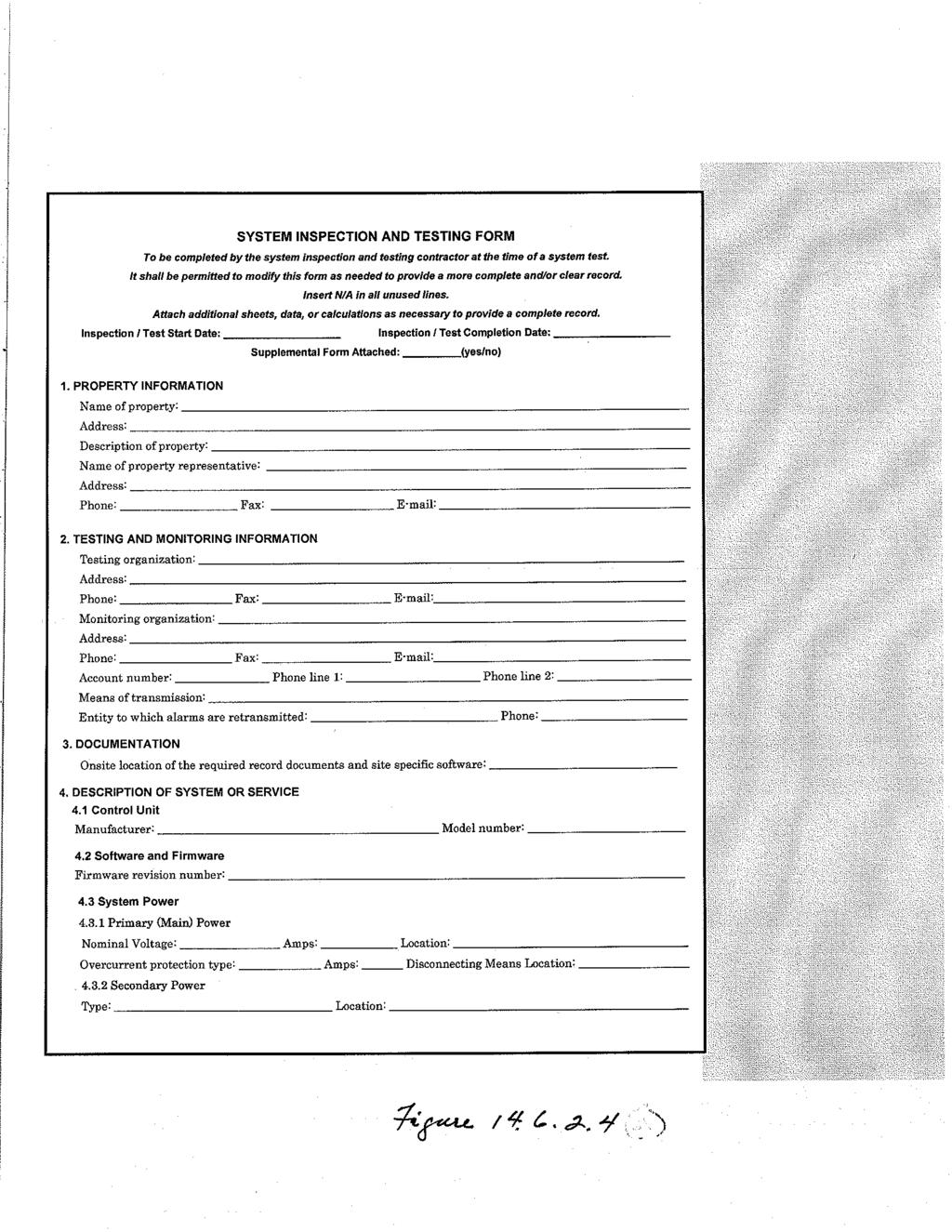
144
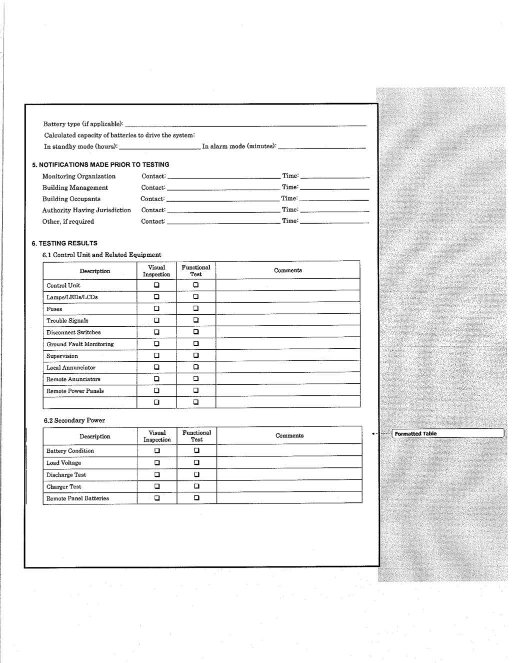
145
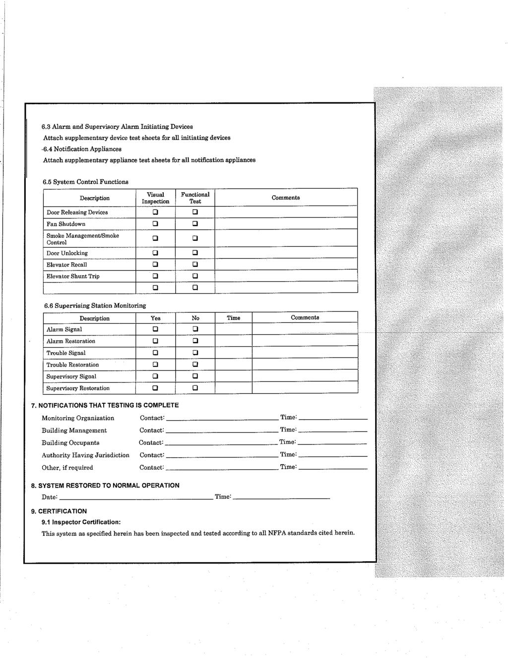
146
National Fire Protection Association. 1 Batterymarch Park, Quincy, MA Phone: Fax:
 National Fire Protection Association 1 Batterymarch Park, Quincy, MA 02169-7471 Phone: 617-770-3000 Fax: 617-770-0700 www.nfpa.org M E M O R A N D U M TO: FROM: Technical Committee on Notification Appliances
National Fire Protection Association. 1 Batterymarch Park, Quincy, MA Phone: Fax:
 National Fire Protection Association 1 Batterymarch Park, Quincy, MA 02169-7471 Phone: 617-770-3000 Fax: 617-770-0700 www.nfpa.org M E M O R A N D U M TO: FROM: NFPA Technical Committee on Notification
AGENDA NFPA TECHNICAL COMMITTEE ON NOTIFICATION APPLIANCES. Report on Comments Meeting, October 13-14, Richmond Marriott, Richmond, VA
 National Fire Protection Association 1 Batterymarch Park, Quincy, MA 02169-7471 Phone: 617-770-3000 Fax: 617-770-0700 www.nfpa.org AGENDA NFPA TECHNICAL COMMITTEE ON NOTIFICATION APPLIANCES Report on Comments
National Fire Protection Association. 1 Batterymarch Park, Quincy, MA Phone: Fax:
 National Fire Protection Association 1 Batterymarch Park, Quincy, MA 02169-7471 Phone: 617-770-3000 Fax: 617-770-0700 www.nfpa.org M E M O R A N D U M TO: FROM: Technical Committee on Protected Premises
Second Revision No. 104-NFPA [ Section No ] Submitter Information Verification. Committee Statement
![Second Revision No. 104-NFPA [ Section No ] Submitter Information Verification. Committee Statement](/thumbs/87/97199093.jpg "Second Revision No. 104-NFPA [ Section No ] Submitter Information Verification. Committee Statement") of 1 9/22/2014 1:38 PM Second Revision No. 104-NFPA 72-2014 [ Section No. 3.3.3 ] 3.3.3 Accessible, Readily (Readily Accessible). Capable of being reached quickly for operation, renewal, or inspections
of 1 9/22/2014 1:38 PM Second Revision No. 104-NFPA 72-2014 [ Section No. 3.3.3 ] 3.3.3 Accessible, Readily (Readily Accessible). Capable of being reached quickly for operation, renewal, or inspections
NFPA 72 Code Changes vs 2013
 NFPA 72 Code Changes - 2010 vs 2013 AFAA-NE Westborough, MA February 7, 2018 Richard Roux NFPA 72 National Fire Alarm and Signaling Code Overview and 2013 Changes NFPA 72 1993 Edition Aug 20, 1993 1996
Update all extract references to NFPA documents (including NFPA 72) in Chapter 3 and related annex material to the latest editions.
 in Chapter 3 and related annex material to the latest editions.") 11/16/12 TerraView First Revision No. 15-NFPA 720-2012 [ Global Input ] Update all extract references to NFPA documents (including NFPA 72) in Chapter 3 and related annex material to the latest editions.
11/16/12 TerraView First Revision No. 15-NFPA 720-2012 [ Global Input ] Update all extract references to NFPA documents (including NFPA 72) in Chapter 3 and related annex material to the latest editions.
Alarm. A warning of danger. An indication of the existence of a condition that requires immediate action. (SIG-FUN)
") 4 of 326 11/21/2013 1:03 PM First Revision No. 161-NFPA 72-2013 [ Section No. 3.3.11 ] 3.3.11 Alarm. A warning of danger. An indication of the existence of a condition that requires immediate action. (SIG-FUN)
4 of 326 11/21/2013 1:03 PM First Revision No. 161-NFPA 72-2013 [ Section No. 3.3.11 ] 3.3.11 Alarm. A warning of danger. An indication of the existence of a condition that requires immediate action. (SIG-FUN)
Table OUT OF SERVICE. Building Fire Video 1/15/ Inspection, testing and maintenance. Standards Further Referenced by FCNYS
 901.6 Inspection, testing and maintenance. Fire detection, alarm and extinguishing systems shall be maintained in an operative condition at all times, and shall be replaced or repaired where defective.
SECTION DIGITAL, ADDRESSABLE FIRE-ALARM SYSTEM
 SECTION 283111 - DIGITAL, ADDRESSABLE FIRE-ALARM SYSTEM PART 1 - GENERAL 1.1 RELATED DOCUMENTS A. Drawings and general provisions of the Contract, including General and Supplementary Conditions and Division
M E M O R A N D U M. NFPA 5000 A2011 ROP Letter Ballot
 M E M O R A N D U M TO: FROM: NFPA Technical Committee on Building Service and Fire Protection Equipment Gregory Harrington, P.E., Staff Liaison DATE: October 1, 2009 SUBJECT: NFPA 5000 A2011 ROP Letter
STANDARDS UPDATE NOTICE (SUN) ISSUED: February 5, 2018
 ISSUED: February 5, 2018") STANDARDS UPDATE NOTICE (SUN) ISSUED: February 5, 2018 STANDARD INFORMATION Standard Number: NFPA 72 Standard Name: National Fire Alarm and Signaling Code Standard Edition and Issue Date: 2016 Edition
STANDARDS UPDATE NOTICE (SUN) ISSUED: February 5, 2018 STANDARD INFORMATION Standard Number: NFPA 72 Standard Name: National Fire Alarm and Signaling Code Standard Edition and Issue Date: 2016 Edition
Automatic Fire Alarm Association Webinar On Inspection, Testing, And Maintenance Of Fire Alarm Systems
 Automatic Fire Alarm Association Webinar On Inspection, Testing, And Maintenance Of Fire Alarm Systems Your Presenter: Merton Bunker, PE Inspections and tests are intended to reduce or limit: Loss of life
FIRE & LIFE SAFTEY STANDARD
 Title: Effective Date: 01/01/14 Revised Date: 1/1/14 Code References: Title 16, Chapter 16.16 of the Roseville Municipal Code, NFPA 72 Note: This standard is a summary of Fire Department clarifications
1. Floor above/floor below notification. 2. Private alarm notification. 3. Not Used 4. Voice alarm notification. 5. Not Used.
 PART 1 GENERAL 1.01 Scope of Standard A. This Standard is intended to assure that fire alarm and signaling systems at Sam Houston State University provide the highest level of life safety possible. This
1.3 REFERENCE STANDARDS
 SECTION 28 4600 FIRE DETECTION AND ALARM PART 1 -GENERAL 1.1 SECTION INCLUDES A. Fire alarm system design and installation, including all components, wiring, and conduit. B. Circuits from protected premises
M E M O R A N D U M. Technical Committee on Supervising Station Fire Alarm and Signaling Systems
 National Fire Protection Association 1 Batterymarch Park, Quincy, MA 02169-7471 Phone: 617-770-3000 Fax: 617-770-0700 www.nfpa.org M E M O R A N D U M TO: FROM: Technical Committee on Supervising Station
National Fire Protection Association M E M O R A N D U M. Technical Committee on Testing and Maintenance of Fire Alarm and Signaling Systems
 National Fire Protection Association 1 Batterymarch Park, Quincy, MA 02169-7471 Phone: 617-770-3000 Fax: 617-770-0700 www.nfpa.org M E M O R A N D U M TO: FROM: Technical Committee on Testing and Maintenance
SANTA CLARA COUNTY Winchester Blvd., Los Gatos, CA (408) (408) (fax)
 (408) (fax)") FIRE DEPARTMENT SANTA CLARA COUNTY 14700 Winchester Blvd., Los Gatos, CA. 95032-1818 (408) 378-4010 (408) 378-9342 (fax) www.sccfd.org STANDARD DETAILS & SPECIFICATIONS Spec No C-4 Rev. Date 03/10/10 SUBJECT:
FIRE DEPARTMENT SANTA CLARA COUNTY 14700 Winchester Blvd., Los Gatos, CA. 95032-1818 (408) 378-4010 (408) 378-9342 (fax) www.sccfd.org STANDARD DETAILS & SPECIFICATIONS Spec No C-4 Rev. Date 03/10/10 SUBJECT:
 Page 1 of 40 First Correlating Revision No. 15-NFPA 72-2014 [ Global Input ] 10.5.4 Plans Examiners and Inspectors. 10.5.4.1 Fire alarm system and emergency communications system plans and specifications
Changes in NFPA
 Changes in NFPA 72-2002 2002 Oregon Fire Code Committee November 25, 2003 Michael B. Baker, SET Automatic Fire Alarm Association MikeBaker@afaa.org 2003 Michael B. Baker 1 Table of Contents 1. Administration
M E M O R A N D U M. NFPA Technical Committee on Building Services and Fire Protection Equipment
 M E M O R A N D U M TO: FROM: NFPA Technical Committee on Building Services and Fire Protection Equipment Linda MacKay DATE: November 10, 2009 SUBJECT: NFPA 5000 A2011 ROP Letter Ballot Final Results The
26 of 128 9/23/2014 9:25 AM
 26 of 128 9/23/2014 9:25 AM Second Revision No. 105-NFPA 72-2014 [ Global Comment ] Revise the Annex F figures that include a smoke detector symbol (hexagon with a whisp of smoke) so that the new smoke
Rancho Cucamonga Fire Protection District Prevention Bureau Standard
 Rancho Cucamonga Fire Protection District Prevention Bureau Standard Title: Fire Alarm and Monitoring Systems Standard # 9-3 Effective: May 2002 Number of Pages: 7 Updated: December 2016 for consistency
The Technical Committee on Commissioning and Integrated Testing
 National Fire Protection Association 1 Batterymarch Park, Quincy, MA 02169-7471 Phone: 617-770-3000 Fax: 617-770-0700 www.nfpa.org TO: FROM: The Technical Committee on Commissioning and Integrated Testing
Florida Building Code Chapter 9 Fire Protection Systems Advanced Course
 Florida Building Code 2010 Chapter 9 Fire Protection Systems Advanced Course 1 Introduction This course will cover specific sections of Chapter 9 that relate to fire alarm systems. While many contractors
Date Issued: December 14, 2017 Revision: 2.1
 2.1 1. Introduction A is implemented to ensure the fire safety of building occupants or a building area when the Fire Alarm System or a Fire Protection System has been temporarily disabled due to malfunction,
Full Service Central Station Fire Alarm Listing Evaluation
 Full Service Central Station Fire Alarm Listing Evaluation Listing Evaluation A UL Listing project includes: 1. Evaluating the central station facility for compliance with UL 827, Central-Station Alarm
Chapter 4: Fire Protection Systems
 Chapter 4: Fire Protection Systems Automatic Extinguishing Systems (Fire Sprinklers) One of the most important aspects of a storage warehouse inspection is ensuring that the automatic extinguishing system
Proposed Changes to NFPA
 2017 NFPA Conference & Expo Proposed Changes to NFPA 72-2019 Presented by: Manuelita David (SIG-FUN), Jensen Hughes Warren Olsen (SIG-SSS), Fire Safety Consultants, Inc. Merton Bunker (SIG-AAC), EYP Architecture
Florida Building Code 2010
 Introduction Florida Building Code 2010 Chapter 9 Fire Protection Systems This course will cover specific sections of Chapter 9 that relate to fire alarm systems. While many contractors are familiar with
MEMORANDUM. NFPA Technical Committee on Fundamentals of Fire Alarm and Signaling Systems (SIG- FUN)
") National Fire Protection Association 1 Batterymarch Park, Quincy, MA 02169-7471 Phone: 617-770-3000 Fax: 617-770-0700 www.nfpa.org MEMORANDUM To: From: NFPA Technical Committee on Fundamentals of Fire
National Fire Protection Association 1 Batterymarch Park, Quincy, MA 02169-7471 Phone: 617-770-3000 Fax: 617-770-0700 www.nfpa.org MEMORANDUM To: From: NFPA Technical Committee on Fundamentals of Fire
Committee Input No NFPA [ Global Input ] Submitter Information Verification. Committee Statement. 1 of /20/ :02 AM
![Committee Input No NFPA [ Global Input ] Submitter Information Verification. Committee Statement. 1 of /20/ :02 AM](/thumbs/75/72631987.jpg "Committee Input No NFPA [ Global Input ] Submitter Information Verification. Committee Statement. 1 of /20/ :02 AM") 1 of 213 10/20/2016 11:02 AM Committee Input No. 2505-NFPA 72-2016 [ Global Input ] Change the term visible to visual where appropriate Submitter Information Verification Submitter Full Name: SIG-NAS Organization:
1 of 213 10/20/2016 11:02 AM Committee Input No. 2505-NFPA 72-2016 [ Global Input ] Change the term visible to visual where appropriate Submitter Information Verification Submitter Full Name: SIG-NAS Organization:
Circulation Report for SIG-TMS Comments Document # 72
 1 72-12 Eligible To Vote:28 Affirmative: 24 : 0 Abstain: 0 : 4 3.3.x Deficiency (New) (Log # 209 ) 72-13 Eligible To Vote:28 Affirmative: 24 : 0 Abstain: 0 : 4 3.3.x Deficiency (New) (Log # 234 ) 72-15
CAN/ULC-S1001, INTEGRATED SYSTEMS TEST OF FIRE PROTECTION AND LIFE SAFETY SYSTEMS
 RANDAL BROWN & ASSOCIATES ENGINEERING LTD. CONSULTING ENGINEERS LIFE SAFETY & FIRE PROTECTION 105 6 LANSING SQUARE TORONTO, ONTARIO CAN/ULC-S1001, INTEGRATED SYSTEMS TEST OF FIRE PROTECTION AND LIFE SAFETY
Fire Alarm System Fundamentals
 Fire Alarm System Fundamentals Mircom is the largest and oldest privately owned fire alarm and life safety manufacturer in North America and 5th largest overall with 50 years of industry experience. Mircom
Fire Alarm Acceptance Testing & On-Going Maintenance with The Joint Comm. Standards / Reporting. Prepared Especially for : OSFM TEC 2016
 Fire Alarm Acceptance Testing & On-Going Maintenance with The Joint Comm. Standards / Reporting Prepared Especially for : OSFM TEC 2016 Acceptance Testing 11-2008 Agenda Before you begin Completing the
CHAPTER 61G15-32 RESPONSIBILITY RULES OF PROFESSIONAL ENGINEERS CONCERNING THE DESIGN OF FIRE PROTECTION SYSTEMS
 CHAPTER 61G15-32 RESPONSIBILITY RULES OF PROFESSIONAL ENGINEERS CONCERNING THE DESIGN OF FIRE PROTECTION SYSTEMS 61G15-32.001 61G15-32.002 61G15-32.003 61G15-32.004 61G15-32.005 61G15-32.006 61G15-32.007
Bold items are particular to the City of Euless
 EULESS FIRE DEPARTMENT FIRE MARSHAL S OFFICE INFORMATION LINE: Revised 8/2004 Fire Chief Lee Koontz Fire Marshal Paul Smith EFD-FMO 3-1 2003 International Fire & Building Code as Amended NFPA Standards
You are required to READ ALL PAGES. of this application
 Fire/Smoke/Heat/CO Application Checklist You are required to READ ALL PAGES of this application NEW ROCHELLE FIRE DEPARTMENT 90 Beaufort Pl, New Rochelle, NY 10801 - (914) 654-2213 APPLICATION FOR FIRE/SMOKE/HEAT/CO
Minimum Standards for Engineers Practicing Fire Protection Engineering in the State of Oklahoma September 14, 2016
 1. Introduction The intent of this document is to establish minimum standards for the practice of fire protection engineering within the State of Oklahoma as conducted by licensed professional engineers.
NFPA Siemens Industry, Inc. All rights reserved. usa.siemens.com/infrastructure-cities
 Fire Alarm and Signaling Code Overview NFPA 72-2010 usa.siemens.com/infrastructure-cities Siemens Building Technologies, Inc. is a Registered Provider with The American Institute of Architects Continuing
First Revision No. 158-NFPA [ Global Input ] Submitter Information Verification. Committee Statement
![First Revision No. 158-NFPA [ Global Input ] Submitter Information Verification. Committee Statement](/thumbs/82/85532588.jpg "First Revision No. 158-NFPA [ Global Input ] Submitter Information Verification. Committee Statement") of 326 11/21/2013 1:03 PM First Revision No. 158-NFPA 72-2013 [ Global Input ] Revise 2.3.1 to update UL 864 to "2003, revised 2012" and upate ANSI/ASME A17 to 2013. Submittal Date: Wed Sep 11 11:08:52
of 326 11/21/2013 1:03 PM First Revision No. 158-NFPA 72-2013 [ Global Input ] Revise 2.3.1 to update UL 864 to "2003, revised 2012" and upate ANSI/ASME A17 to 2013. Submittal Date: Wed Sep 11 11:08:52
THIS ORDINANCE ONLY AFFECTS EXISTING FIRE ALARM SYSTEMS.
 THIS ORDINANCE ONLY AFFECTS EXISTING FIRE ALARM SYSTEMS. IF YOU RECEIVED A NOTICE BY MAIL AND YOU DO NOT CURRENTLY HAVE A FIRE ALARM INSTALLED IN YOUR BUILDING, YOU MAY DISREGARD THE NOTICE. Dear Building
NORTHWESTERN UNIVERSITY PROJECT NAME JOB # ISSUED: 03/29/2017
 SECTION 21 0800 - COMMISSIONING OF FIRE SUPPRESSION SYSTEMS GENERAL 1.1 SUMMARY General 1. Work under this contract shall meet the requirements of Division 01, General Requirements, Conditions of Contract,
APPENDIX H (DESIGN SUBMISSION CRITERIA)
") APPENDIX H (DESIGN SUBMISSION CRITERIA) FIRE ALARM SYSTEM As per ACCORD standard Part 5, section 5.7 Fire Alarm System Design to be verified by ACCORD Chief Safety Inspector. Testing of the installation
APPENDIX H (DESIGN SUBMISSION CRITERIA) FIRE ALARM SYSTEM As per ACCORD standard Part 5, section 5.7 Fire Alarm System Design to be verified by ACCORD Chief Safety Inspector. Testing of the installation
Standard of Practice - Fire Alarm Systems. NOTE: Significant revisions or additions to the previous standards are highlighted in italics.
 A28.1 Standard of Practice - Fire Alarm Systems NOTE: Significant revisions or additions to the previous standards are highlighted in italics. OBJECTIVE OF STANDARD To provide compliant smart addressable
Fire System Impairment Policy
 Fire System Impairment Policy Purpose: To establish procedures to be followed, when a fire protection or suppression system is taken out of service, due to construction, alteration, power outage, repair,
Michigan State University Construction Standards FIRE DETECTION AND ALARM PAGE
 PAGE 283100-1 SECTION 283100 - DIGITAL, ADDRESSABLE FIRE-ALARM SYSTEM PART 1 - GENERAL 1.1 RELATED DOCUMENTS A. Drawings and general provisions of the Contract, including General and Supplementary Conditions
CLARK COUNTY FIRE DEPARTMENT Fire Prevention Bureau
 CLARK COUNTY FIRE DEPARTMENT Fire Prevention Bureau 575 E. Flamingo Road, Las Vegas, NV 89119 (702) 455-7316 FAX (702) 455-7347 Permit Type: 105.6.54 Control Number: A.0 Effective Date: TITLE: PROPRIETARY
ALARM SYSTEMS AND EVACUATION PLANS SELF INSPECTION CHECKLIST
 OPTIONAL INFORMATION Name of School: Date of Inspection: Vocational Program/Course/Room: Signature of Inspector: ALARM SYSTEMS AND EVACUATION PLANS Guidelines: This checklist covers regulations issued
MEMORANDUM. Technical Committee on Fundamentals of Fire Alarm and Signaling Systems
 National Fire Protection Association 1 Batterymarch Park, Quincy, MA 02169-7471 Phone: 617-770-3000 Fax: 617-770-0700 www.nfpa.org MEMORANDUM TO: FROM: Technical Committee on Fundamentals of Fire Alarm
RULES OF DEPARTMENT OF COMMERCE AND INSURANCE DIVISION OF FIRE PREVENTION CHAPTER FIRE EXTINGUISHERS TABLE OF CONTENTS
 RULES OF DEPARTMENT OF COMMERCE AND INSURANCE DIVISION OF FIRE PREVENTION CHAPTER 0780-02-14 FIRE EXTINGUISHERS TABLE OF CONTENTS 0780-02-14-.01 Definitions 0780-02-14-.09 Restrictions 0780-02-14-.02 Standards
MEMORANDUM. SUBJ: NFPA 72 Proposed TIA No FINAL CC BALLOT RESULTS
 National Fire Protection Association 1 Batterymarch Park, Quincy, MA 02169-7471 Phone: 617-770-3000 Fax: 617-770-0700 www.nfpa.org MEMORANDUM TO: FROM: NFPA Correlating Committee on Signaling Systems for
Report on First Revision June 2014 NFPA 5000
 5000- Log #12 BLD-BSF Final Action: (55.2 (New) ) NOTE: This proposal appeared as Comment 5000-168 (Log #86) which was held from the A11 ROC on Proposal 5000-239. Submitter: Technical Correlating Committee
Moreno Valley Fire Department Fire Prevention Bureau. New and Existing Fire Alarm & Signaling Systems Guideline
 Moreno Valley Fire Department Guideline Approved and Authorized By: Adria Reinertson, Fire Marshal Issued: May 8, 2017 Alarm & Signaling Systems PURPOSE Fire alarm and signaling systems are designed to
MNEC NFPA 72 WHITE PAPER
 MNEC NFPA 72 WHITE PAPER In 2010, the National Fire Protection Assocation (NFPA), significantly changed their code # 72 (National Fire Alarm Code) and has forever improved the importance of communicating
SECTION FIRE ALARM SYSTEMS
 SECTION 28 3100 PART 1 -GENERAL 1.01 RELATED DOCUMENTS Drawings and general provisions of the Contract, including General and Supplementary Conditions and Division 1 Specification Sections, apply to this
Fire Permit Application
 Fire Permit Application FOR STAFF USE ONLY Case Permit Number: Plan Number: Related permits: Project #: Responsibility for information Although designated Department staff members will help you with general
Committee on NFPA 85
 Committee on NFPA 85 M E M O R A N D U M TO: FROM: NFPA Technical Committee on Single Burner Boilers Patti Mucci, Technical Assistant II DATE: August 5, 2009 SUBJECT: NFPA ROP Letter Ballot The ROP letter
M E M O R A N D U M. NFPA Technical Committee on Alternative Approaches to Life Safety. SUBJECT: NFPA 101A ROP TC Letter Ballot (A2012 Cycle)
") M E M O R A N D U M TO: FROM: NFPA Technical Committee on Alternative Approaches to Life Safety Linda MacKay DATE: December 28, 2010 SUBJECT: NFPA 101A ROP TC Letter Ballot (A2012 Cycle) The ROP letter
M E M O R A N D U M TO: FROM: NFPA Technical Committee on Alternative Approaches to Life Safety Linda MacKay DATE: December 28, 2010 SUBJECT: NFPA 101A ROP TC Letter Ballot (A2012 Cycle) The ROP letter
2. HVAC and smoke control systems; fire, smoke, and combination fire/smoke dampers. 5. Central control and monitoring system.
 PART 1 GENERAL 1.01 Scope of Standard A. This Standard is intended to assure that fire detection/alarm systems at The University of Texas at Austin provide the highest level of fire safety possible.. This
Agenda Technical Committee on Initiating Devices for Fire Alarm and Signaling Systems June 24-25, 2013 Saint Louis, MO
 Agenda Technical Committee on Initiating Devices for Fire Alarm and Signaling Systems June 24-25, 2013 Saint Louis, MO Item No. Subject 13-6-1 Call to Order (8:00 A.M) 13-6-2 Roll Call 13-6-3 Approval
Advanced Fire Alarm Systems Training Program Outline (5 Day)
") Advanced Fire Alarm Systems Training Program Outline (5 Day) Day 1 Prescriptive and Performance-Based Design Understand the methodology in accessing the threat of fire within a structure. Know the difference
Advanced Fire Alarm Systems Training Program Outline (5 Day) Day 1 Prescriptive and Performance-Based Design Understand the methodology in accessing the threat of fire within a structure. Know the difference
The 2013 National Fire Alarm and Signaling Code
 ARE YOU A MEMBER OF AFAA? WHY SHOULD YOU BE A MEMBER BECAUSE YOUR BUSINESS IS IMPORTANT James Mongeau The 2013 National Fire Alarm and Signaling Code 1 NFPA 72 Organization Be*er organiza2on Easier to
Second Correlating Revision No. 21-NFPA [ Global Input ]
![Second Correlating Revision No. 21-NFPA [ Global Input ]](/thumbs/96/128256336.jpg "Second Correlating Revision No. 21-NFPA [ Global Input ]") Second Correlating Revision No. 21-NFPA 72-2017 [ Global Input ] Change "published manufacturer's instructions" and "manufacturer's instructions" to "manufacturer's published instructions" in accordance
Second Correlating Revision No. 21-NFPA 72-2017 [ Global Input ] Change "published manufacturer's instructions" and "manufacturer's instructions" to "manufacturer's published instructions" in accordance
I. Scope: II. Environmental Health and Safety Fire Alarm System Impairment Program - Guideline Revision Date: April, 2018
 Environmental Health and Safety Fire Alarm System Impairment Program - Guideline Revision Date: April, 2018 Prepared by: EH&S The probability of casualties and major structural damage increases when fire
MEMORANDUM. Technical Committee on Notification Appliances for Fire Alarm and Signaling Systems
 National Fire Protection Association 1 Batterymarch Park, Quincy, MA 02169-7471 Phone: 617-770-3000 Fax: 617-770-0700 www.nfpa.org MEMORANDUM TO: FROM: Technical Committee on Notification Appliances for
CAN/ULC-S1001, INTEGRATED SYSTEMS TESTING OF FIRE PROTECTION & LIFE SAFETY SYSTEMS Simon Crosby, LEL, CET, CFPS October 21, 2015
 CAN/ULC-S1001, INTEGRATED SYSTEMS TESTING OF FIRE PROTECTION & LIFE SAFETY SYSTEMS Simon Crosby, LEL, CET, CFPS October 21, 2015 Fire Commissioning in Canadian Codes and Standards BACKGROUND Why Commissioning?
SAFETY CODES COUNCIL ORDER. BEFORE THE FIRE TECHNICAL COUNCIL On June 21, 2012
 SAFETY CODES COUNCIL #1000, 10665 Jasper Avenue N.W., Edmonton, Alberta, Canada, T5J 389 Tel: 780-413-0099 I 1-888-413-0099 Fax: 780-424-5134 I 1-888-424-5134 www.safetycodes.ab.ca COUNCIL ORDER No. 0015423
STATE FIRE MARSHAL S REQUIRED FIRE PROTECTION SYSTEMS NARRATIVE REPORT
 STATE FIRE MARSHAL S REQUIRED FIRE PROTECTION SYSTEMS NARRATIVE REPORT The interaction of fire protection systems can be extremely complex. The detection of a fire in a building by an automatic device
JEFFERSON COUNTY PUBLIC SCHOOLS FIRE WATCH PROGRAM
 1 JEFFERSON COUNTY PUBLIC SCHOOLS FIRE WATCH PROGRAM PURPOSE: To minimize potential structural damages and to protect the life safety of all building occupants during periods when the automatic fire alarm
Subject: Fire Protection Impairment Program Reference: NFPA (see bottom of page 5) Effective Date: August 2014 Distribution All YC Employees
 Effective Date: August 2014 Distribution All YC Employees") Subject: Fire Protection Impairment Program Reference: NFPA (see bottom of page 5) Effective Date: August 2014 Distribution All YC Employees Purpose: To establish procedures to be followed when a fire
Subject: Fire Protection Impairment Program Reference: NFPA (see bottom of page 5) Effective Date: August 2014 Distribution All YC Employees Purpose: To establish procedures to be followed when a fire
Unified Fire Authority - Fire Prevention Bureau
 Unified Fire Authority - Fire Prevention Bureau FIRE ALARM AND EMERGENCY COMMUNICATION SYSTEM RECORD OF COMPLETION To be completed by the system installation contractor at the time of system acceptance
NFPA Changes
 Chapter 21, Emergency Control Functions and Interfaces Summary. Chapter 21 is new. These requirements were formerly found in Chapter 6, Protected Premises Fire Alarm Systems. The term fire safety function
NFPA Changes
 Chapter 12, Circuits and Pathways Summary. Chapter 12, Circuits and Pathways, is a new chapter. It brings together requirements that were formerly found in SIG-FUN, Fundamentals of Fire Alarm Systems regarding
DEPARTMENT OF PUBLIC SAFETY DIVISION OF FIRE PREVENTION AND CONTROL
 DEPARTMENT OF PUBLIC SAFETY DIVISION OF FIRE PREVENTION AND CONTROL RULES AND REGULATIONS CONCERNING 8 CCR 1507-57 BUILDING AND FIRE CODE ENFORCEMENT AND CERTIFICATION OF INSPECTORS FOR LIMITED GAMING
Control Panel. 1.0 GENERAL SCOPE OF WORK Introduction... 2
 Architectural & Engineering Specifications Control Panel 1.0 GENERAL... 2 1.1 SCOPE OF WORK... 2 1.1.1 Introduction... 2 1.2 GENERAL CONDITIONS... 2 1.2.1 After-Sales Support... 2 1.2.2 Quality assurance...
SECTION FIRE ALARM STANDARDS REVISED CONSTRUCTION STANDARD
 PART 1 - GENERAL PURPOSE This Standard is intended to assure that fire detection/alarm systems at The University of Texas at Austin provide the highest level of fire safety possible. SCOPE This standard
Minutes of the Pre-ROP Meeting of the T/C on Protected Premises Signaling September 22-23, 2010 Indianapolis, IN
 Minutes of the Pre-ROP Meeting of the T/C on Protected Premises Signaling September 22-23, 2010 Indianapolis, IN Mr. Merton Bunker, Committee Chair, called the meeting to order at 8:05 on Wednesday September
Fire Alarm, Water Flow Alarm & Signaling Systems
 Orange County Fire Authority Community Risk Reduction 1 Fire Authority Road, Building A, Irvine, CA 92602 www.ocfa.org 714-573-6100 Fire Alarm, Water Flow Alarm & Signaling Systems Guideline D-03 Serving
Public Notice of Amendment to New Shoreham General Ordinances Chapter 5 Fire Prevention and Protection New Article IV Fire Alarm Ordinance
 Public Notice of Amendment to New Shoreham General Ordinances Chapter 5 Fire Prevention and Protection New Article IV Fire Alarm Ordinance It is ordained by the Town Council of the Town of New Shoreham
PART 1 GENERAL Quality Assurance A. Fire Alarm Contractor Qualifications:
 PART 1 GENERAL 1.01 Quality Assurance A. Fire Alarm Contractor Qualifications: 1 The Fire Alarm contractor shall be an Edwards Systems Technology (EST) designated representative and authorized to sell,
PART 1 GENERAL Quality Assurance A. Fire Alarm Contractor Qualifications:
 PART 1 GENERAL 1.01 Quality Assurance A. Fire Alarm Contractor Qualifications: 1 The Fire Alarm contractor shall be an Edwards Systems Technology (EST) designated representative and authorized to sell,
First Revision No. 339-NFPA [ Section No. 2.2 ]
![First Revision No. 339-NFPA [ Section No. 2.2 ]](/thumbs/73/69137555.jpg "First Revision No. 339-NFPA [ Section No. 2.2 ]") 8 of 326 11/21/2013 1:03 PM First Revision No. 339-NFPA 72-2013 [ Section No. 2.2 ] 2.2 NFPA Publications. National Fire Protection Association, 1 Batterymarch Park, Quincy, MA 02169-7471. NFPA 10, Standard
8 of 326 11/21/2013 1:03 PM First Revision No. 339-NFPA 72-2013 [ Section No. 2.2 ] 2.2 NFPA Publications. National Fire Protection Association, 1 Batterymarch Park, Quincy, MA 02169-7471. NFPA 10, Standard
National Fire Protection Association. 1 Batterymarch Park, Quincy, MA Phone: Fax:
 National Fire Protection Association 1 Batterymarch Park, Quincy, MA 02169-7471 Phone: 617-770-3000 Fax: 617-770-0700 www.nfpa.org M E M O R A N D U M TO: FROM: NFPA Technical Committee on Mercantile and
Functional Challenges of Integrating Mass Notification and Fire Alarm Systems
 Functional Challenges of Integrating Mass Notification and Fire Alarm Systems By Scott Lacey FPE, CSP, SFPE President Lacey Fire Protection Engineering February 12, 2007 Abstract: By Scott Lacey, FPE,
National Fire Protection Association. 1 Batterymarch Park, Quincy, MA Phone: Fax:
 National Fire Protection Association 1 Batterymarch Park, Quincy, MA 02169-7471 Phone: 617-770-3000 Fax: 617-770-0700 www.nfpa.org M E M O R A N D U M TO: FROM: NFPA Technical Committee on Hot Work Operations
COMMISSION ORDER. IT IS FURTHER ORDERED that the Request for Bid and Notice to Bidders be displayed on the Franklin County website.
 4.e STATE OF MISSOURI County of Franklin ss. COMMISSION ORDER Commission Order No. 2016-316 Third Quarter Term 2016 Tuesday,August,09,2016 Bid Notice IN THE MATTER OF ADVERTISING FOR SEALED BIDS FOR SMOKE
CAN/ULC-S INTEGRATED SYSTEMS TESTING OF FIRE PROTECTION AND LIFE SAFETY SYSTEMS
 2013 Randal Brown & Associates Engineering Ltd. 1 RANDAL BROWN & ASSOCIATES ENGINEERING LTD. CONSULTING ENGINEERS LIFE SAFETY & FIRE PROTECTION 105 6 LANSING SQUARE TORONTO, ONTARIO CAN/ULC-S1001-11 INTEGRATED
SECTION FIRE DETECTION AND ALARM
 PART 1 - GENERAL 1.1 RELATED SECTIONS: Refer to Section 15300 for requirements regarding fire protection systems. 1.2 SCOPE OF SECTION: This section contains the requirements for equipment and installation
Austin Independent School District Police Department Policy and Procedure Manual
 Policy 8.07 Austin Independent School District Police Department Policy and Procedure Manual Life Safety Systems I. POLICY The proper operations of the AISD Life Safety Systems (LSS) are essential for
El Reno Fire Department Fire Alarm Plan Review Worksheet
 El Reno Fire Department Fire Alarm Plan Review Worksheet This Fire Alarm Plan Review Checklist is provided as a guide to assist with your Fire Alarm Plan Review Submittal requirements. Please contact us
PWGSC Ontario MULTIPLEX FIRE ALARM SYSTEM Sect Region Project Page 1 Number R
 Region Project Page 1 PART 1 - GENERAL 1.1 REFERENCES.1 CAN/ULC-S524-2006, Standard for the Installation of Fire Alarm Systems..2 CAN/ULC-S525-2007, Audible Signal Device for Fire Alarm Systems..3 CAN/ULC-S526-2007,
Brighton Area Fire Authority
 615 W. Grand River Ave. Brighton, MI 48116 o: 810-229-6640 f: 810-229-1619 January 14, 2019 Fire Alarm Contractors RE: Fire Alarm Credential & Submittal Requirements To Whom It May Concern: The following
Hinesville First United Methodist Church SECTION DIGITAL, ADDRESSABLE FIRE-ALARM SYSTEM
 SECTION 28 3111 DIGITAL, ADDRESSABLE FIRE-ALARM SYSTEM PART 1 - GENERAL 1.01 SUMMARY A. Section Includes: 1. Fire-alarm control unit. 2. Manual fire-alarm boxes. 3. System smoke detectors. 4. Heat detectors.
DIGITAL, ADDRESSABLE FIRE ALARM SYSTEM
 SECTION 283111 - DIGITAL, ADDRESSABLE FIRE-ALARM SYSTEM PART 1 - GENERAL 1.1 RELATED DOCUMENTS A. Drawings and general provisions of the Contract, including General and Supplementary Conditions and Division
Functional Performance Test
 Fire Alarm Control Panel & Fire Alarm Annunciator Panel Notify all building occupants that testing will be conducted. Fire alarm contractor shall have personnel with 2-way radios at the fire alarm control
M E M O R A N D U M. Please do not vote negatively because of editorial errors. However, please bring such errors to my attention for action.
 M E M O R A N D U M TO: FROM: NFPA Technical Committee on Fire Marshal Professional Qualifications Stacey Van Zandt DATE: July 13, 2010 SUBJECT: NFPA 1037 ROP TC Letter Ballot (F2011) The ROP letter ballot
UNIVERSITY. Facilities Management
 EAST TENNESSEE STATE UNIVERSITY Facilities Management Policy Number: 700.10 Title: Fire Protection Impairment Program Implementation Date: April, 2008 Last Revised: August 4th, 2014 Introduction The probability