KC-400 KC-600 KC-700 KC-800 KC-900
|
|
|
- Meredith Curtis
- 6 years ago
- Views:
Transcription
1 KCE Series Micro Processor Controller Operation Manual KC-400 KC-600 KC-700 KC-800 KC-900 KCE
2 Contents 1 Safety Guide Specifications Model Selection Guide Model Guide Optional Spec Dimension & Panel cutout Wiring Terminals KC KC KC KC KC Input Actuations Modify Input Type TC RTD Input type selection TC 4~20mA (Linear) Modify Hardware TC 4~20mA(Linear) Modify Software TC 0~10V Modify Hardware TC 0~10V Modify Software Panel Appearance LED Display Key and Lamp instruction Bar Graph indicators (Output percentage lamp instruction) Auto tuning Parameters Level switch First Level list(user Level) Error information Second Level list (PID Level) LOCK (Security) Third Level list (INPUT Level) INPT Code( Input type selection ) Fourth Level list (SET Level) Program Level list (Display in programmable controller ) 2.10 Event (Display in programmable controller)... 25
3 Contents Functions St 8 ~ (Display in programmable controller) Applications Alarm time (ALA1/ALA2/ALA3) STAL Soft Filter 3.3 ( Available for output type SCR) Alarm mode (ALA1/ALA2/ALA3)... 27
4 1 Safety Guide Warning An external device must be installed if failure of this instrument could result damage to the instrument, equipment or injury to personnel. This instrument is not intended for use in locations subject to flammable or explosive gases. Do not touch high-voltage connections such as power supply terminals, ect. to avoid electric shock. All wiring must be completed before power is turned on to prevent electric shock, fire or damage instrument and equipment. This instrument must be used in accordance with the specifications to prevent fire or damage to instrument and equipment. KCE is not responsible if this instrument is repaired, modified or disassembled by other than factory-approved personnel. Malfunction can occur and warranty is void under these conditions. Caution This is a Class A instrument. In a domestic environment, this instrument may cause radio interference, in which case the user may be required to take adequate measures. This instrument is protected from electric shock by reinforced insulation. Provide reinforced insulation between the wire for the input signal and wires for instrument power supply, source of power and loads. If input/output or signal lines within the building are longer than 30 meters or If input /output or signal lines leave the building, regardless the length. Be sure to provide an appropriate surge control circuit respectively. This instrument is designed for installation in an enclosed instrumentation panel. All high-voltage connections such as power supply terminals must be enclosed in the instrumentation panel to avoid electric shock by operating personnel. All precautions described in this manual should be taken to avoid damage to the instrument or equipment. All wiring must be in accordance with local codes and regulations. To prevent instrument damage of failure, protect the power line and the input/output lines from high currents with a protection device such as fuse, circuit breaker, ect. Tighten each terminal screw to the specified torque found in the manual to avoid electric shock, fire or malfunction. Do not connect wires to unused terminal as this will interfere with proper operation of the instrument. Do not connect modular connectors to telephone line. Maintenance All wiring must be completed before power is turned on to prevent electric shock, instrument failure, or incorrect action. The power must be turned off before repairing work for input break and output failure including replacement of sensor, contactor or SSR, and all wiring must be completed before power is turned on again. Prevent metal fragments or lead wire scraps from falling inside instrument case to avoid electric shock, fire or malfunction. For proper operation of this instrument, provide adequate ventilation for heat dispensation. Turn off the power supply before cleaning the instrument. Do not use a volatile solvent such as paint thinner to clean the instrument. Deformation or discoloration will occur. Use a soft, dry cloth to remove stains from the instrument. To avoid damage to instrument display, do not rub with an abrasive material or push front panel with a hard object. 1
5 1.1 Specifications Model KC-400 KC-700 KC-600 KC-800 KC-900 Size mm mm mm mm mm Weight 170g 270g 250g 250g 330g Power Consumption General Specifications 3VA 3VA 4VA 4VA 4VA Rated Power Supply Voltage & Frequency Ambient Temperature& Humidity A85~265V,50/60Hz 0~50,20-85%RH(Non condensing) TC K,J,R,S,B,E,N,T,W,PLII,U,L PV Input Input Type RTD Linear PT100,JPT100,JPT50 0~1V,0~5V,0~10V,1~5V,2~10V,- 10~10 mv,0~10 mv,0~20 mv,0-50 mv,10~50 mv,4~20 ma,0~20 ma Input sampling Time 250ms Indication Control Mode Output Alarm Input Resolution PV/SP Indication Constant Value Storage System Indication Accuracy Proportional Band(P) Integral Time(I) Derivative Time(D) Cycle Time Dead Band Time Relay Output Relay Voltage Output Linear Output Alarm Output Alarm Mode Alarm Timer 16 bit (Each) 4-digit,7 segment display Non-volatile memory (E 2 PROM) 0.5%FS 0~200% (On/off action at P=3.0) 0~3600 sec (PD action at I=120) 0~900 sec (PI action at D=30) 0~150 se c(4~20ma 0,SSR 1,Relay 10) 0~1000 sec (Dead time compensation) Contact,SPDT,8A/240VAC Voltage Pulse,4VDC/20mA 4~20mA,0~5V,0~10V,1-5V,2-10V 3A,220V 17 alarm Modes Available Flicker Alarm Continued Alarm On Delay Timer Alarm 2

 Output 1 Proportional Motor valve control 1φPhase Angle Control(1φSCR-P) 3φPhase Angle Control(3φSCR-P)")
6 1.2 Model Selection Guide 1.3 Model Guide KC-900(96 96mm) KC-800(48 96mm) KC-700(72 72mm) KC-600(96 48mm) KC-400(48 48mm) 1.4 Optional Spec. Available Unavailable Model Function KC-400 KC-600 KC-700 KC-800 KC-900 1φZero Crossing Control(1φSCR-Z) 3φZero Crossing Control(3φSCR-Z) Output 1 Proportional Motor valve control 1φPhase Angle Control(1φSCR-P) 3φPhase Angle Control(3φSCR-P) Programmable RATE / SOAK Output 2 Alarm2 Alarm3 Heater Break Alarm (HBA) Transmission (TRS) Remote SV Communication DC 24V Power 3


7 1.5 Dimension & Panel cutout (Unit:mm) KC-400(48 48mm) KC-700(72 72mm) KC-600(96 48mm) KC-800(96 48mm) KC-900(96 96mm) 4


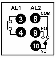
 Alarm AL2")
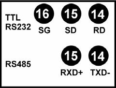
 Communication")
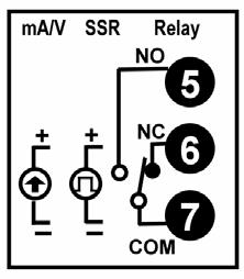
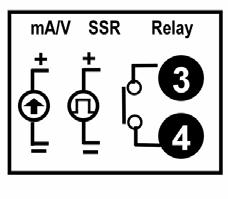
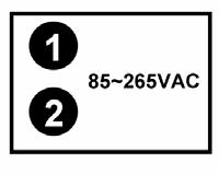
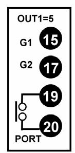
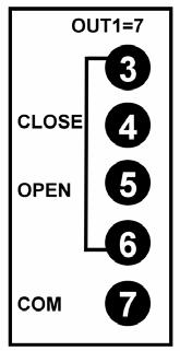
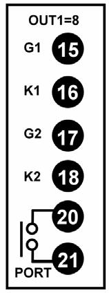
8 1.6 Wiring Terminals KC-400 Terminals arrangement Power KCE Series Micro Processor Controller Operation Manual Output OUTI OUT2 Input OUT1 (1ψZero Crossing Control) OUT1 (Proportional Motor valve control) Alarm AL2 AL3 Transmission (TRS) Communication Double Output- Proportional Motor valve control 5

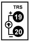
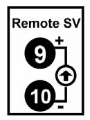
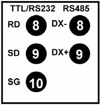
9 1.6.2 KC-700 Terminals arrangement OUTI Output OUT2 Power OUT1 (1ψZero Crossing Control) OUT1 (Proportional Motor valve control) OUT1(1φPhase Angle Control) Input Transmission (TRS) Remote SV Communication Alarm 6


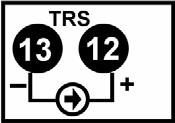
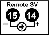
10 1.6.3 KC-600 KCE Series Micro Processor Controller Operation Manual Terminals arrangement Input Power Output OUTI OUT2 Alarm OUT1 (Proportional Motor valve control) OUT1 (1ψZero Crossing Control) Communication Transmission (TRS) Remote SV 7


")

11 1.6.4 KC-800 KCE Series Micro Processor Controller Operation Manual Terminals arrangement Input Alarm Output OUTI OUT2 Power Transmission (TRS) OUT1 (Proportional Motor valve control) OUT1(1φPhase Angle Control) Communication Remote SV 8


")

 OUT1")
")
12 1.6.5 KC-900 KCE Series Micro Processor Controller Operation Manual Terminals arrangement Alarm Input Power Communication Remove SV +Communication Output OUTI OUT2 Transmission (TRS) Remote SV OUT1 (1ψ Zero Crossing Control) OUT1 (3ψZero Crossing Control) OUT1 (Proportional Motor valve control) OUT1(1φPhase Angle Control) OUT1(3φPhase Angle Control) 9

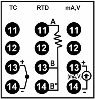
. TC TC RTD RTD 1.8.2 TC 4-20 ma (Linear) Modify Hardware Please make S1 to be a short circuit as following drawing.")
13 1.7 Input Actuations K 0.0~200.0,400.0,600.0,800.0,1000, 1200 KCE Series Micro Processor Controller Operation Manual PT100Ω ~600.0,400.0, ~200.0,400.0,600.0 J 0.0~200.0,400.0,600.0,800.0,1000, 1200 RTD J PT100Ω ~600.0,400.0, ~200.0,400.0,600.0 TC R 0.0~1600,1769 S 0.0~1600,1769 AN1 JPT50Ω ~600.0,400.0, ~200.0,400.0, ~10mv,±2V, ±5V,±10V B 0.0~1820 AN2 0-10mV E 0.0~800,1000 Linear AN3 0~20mV N 0.0~1200,1300 AN4 0~50mv,0~20mA,0~5V,0~10V T 0.0~400.0,200.0,0.0~350.0 W 0.0~2000,2320 AN5 4~20mv,1~5V,2~10V PLII 0.0~1300,1390 U ~600.0,200.0,0.0~400.0 L 0.0~400.0, Modify Input Type TC RTD Input type selection To select Input type at INPT in Level 3(SET Level). TC TC RTD RTD TC 4-20 ma (Linear) Modify Hardware Please make S1 to be a short circuit as following drawing. 10


14 1.8.3 TC 4-20 ma (Linear) Modify Software Step: 1. Set St-2-2=1,Parameter INLO/INHI/DP will show in LEVEL 3 2. Set INPT from K2 to AN5 in LEVEL 3(INPUT Level) 3. Parameter DP can change the decimal point position KCE Series Micro Processor Controller Operation Manual 4. Use Multifunction Calibrator to adjust Level 4 St-2-2=1 Level 3 Into SET LEVEL Set St-2-2=1,Parameter INLO/INHI/DP will show in LEVEL 3 Into INPUT LEVEL Presumption value INLO=0 /INHI=5000 Adjust PVLO & PVHI Multifunction Calibrator INLO= ZERO INHI= SPAN Setting the measuring range: PVLO~PVHI Presumption value K2=0.0~400.0 AN5=0.0~ mA Input 4mA current Input 20mA current 20mA Adjust Parameter INLO until PV=PVLO Adjust Parameter INHI until PV=PVHI Adjusted SV by UP and DOWN key until PV = PVLO NO Check Input 4mA PV=PVLO Input 20mA PV=PVHI YES Calibration finished Adjusted SV by UP and DOWN key until PV = PVHI Ex1: Type AN5 =Input 4~20mA Setting range 0.0~100.0 PVLO=0.0 PVHI=100.0 INLO -212 INHI 4141 Ex2: Type AN4 =Input 4~20mA Setting range 4.0~20.0 PVLO=0.0 PVHI=20.0 INLO INHI 1293 *(The value will have individual differences ) 11


15 1.8.4 TC 0-10V (Linear) Modify Hardware 1. Please make S1 short circuit as following drawing. 2. Cut the line between S2 and put a resistance (2K) on S2 and fixed it by soldering TC 0-10V (Linear) Modify Software Step: 1. Set St-2-2=1,Parameter INLO/INHI/DP will show in LEVEL 3 2. Set INPT from K2 to AN4 in LEVEL 3(INPUT Level) 3. Parameter DP can change the decimal point position 4. Use Multifunction Calibrator to Calibration 12
 S V:Set Value, 4")


 Output pattern(2 patterns) 1.9.")
16 1.9 Panel Appearance 1.1 Display KC-900 KC-800 KC-700 KC-600 KC LED Display P V:Process Value, 4 LED display (Red color) S V:Set Value, 4 LED display (Green color) Key and Lamp instruction Symbol Name Symbol Name Symbol Name SET key OUT1 Output1,Green color AL3 Alarm 3,Red color Auto/Manual key. OUT2 Output2,Green color MAN Manual,Yellow color Shift key A T Auto Tuning,Yellow color PRO Program,Yellow color Down key AL1 Alarm 1,Red color OUT% Output percentage Up key AL2 Alarm 2,Red color Bar Graph indicators (Output percentage lamp instruction) Output segment(8 segment s) Output pattern(2 patterns) Auto tuning When AT (USER LEVEL) is set to YES,auto tuning will start. When set to NO,auto tuning will close. 13
 When LOCK=0,Press the")
 level Press the 5 sec.")
 level Third Level (INPUT Level) When")

17 2 Parameters 2.1 Level switch First Level (USER Level) When LOCK=0,Press the + key, into third (INPUT) level Press the + key back to first (USER) level Press the 5 sec. Second Level (PID Level) When LOCK=0,Press the + key,into third(input) level Third Level (INPUT Level) When LOCK=1111,Press the + key,into fourth(set) level How to return First level: 1 The controller will return to First level If user without Fourth Level (SET Level) any operation within 60 seconds. 2 Press AUT/MAN key twice. 14


 Set Alarm 1 0 *ALA2")


18 2.2 First Level list (USER Level) PV Process Value Note1 *PV Two SV display SV Set Value 100 / (Need add hardware) PV OFF /25 Press key to turn ON or OFF To enter PID Level (Press key 5 seconds) AT YES / NO AutoTuning Note2 *A 0.0 HBA (CT Fault Alarm) ALA1 0.0 (Need add hardware) Set Alarm 1 0 *ALA2 Set Alarm 2 0 Note3 OUTP Press key *ALA3 to display Output percentage Set Alarm 3 0 *OUTL PV Press key to close SV Set Output Low Limit display (St-4-1=1) 0 OFF *OUTH 100 Set Output High Limit * Hiding function Return to PV Note 1: Two SV display Note 2: CT Fault Alarm (HBA) Note 3: Output percentage 15
19 2.3 Error information Display Description Note 1NER Input 1 error 2NER Temperature is too high INHI PV exceeds PVHI INLO PV under PVLO 2NHI 2NLO ATER PV2 exceeds PVHI PV2 under PVLO Auto tuning failed. When the error marked show up,please send it to the nearest sales office or retail dealer IFER Interface failed. ADER A/D convert failed. CJER Cold junction compensation failed. RDER RAM failed. 16
20 2.4 Second Level list (PID Level) Press key for 5 seconds to enter Second Level P-1 Range:0-200% HYS1 Proportional Band Time Display when P1=0 0.0 Display when output 2 is provided I-1 Integral Time D-1 Derivative Time 1 30 DB-1 Dead-band Time AT-L Auto tuning offset value 5.0 CY-1 15 Cycle Time 1 Range: seconds Range:0-900 seconds Range:0-100 Range:0-400 Relay 15 SSR 1 seconds SCR 0 seconds Hysteresis for output 1 ON / OFF Control OFF: PV > SV + HYS1 ON :PV < SV - HYS1 * P-2 Range:0-200% HYS2 Proportional Band Time Display when P2=0 0.0 * I-2 Integral Time * D-2 Derivative Time 2 30 * CY-2 15 Cycle Time2 * GAP.1 Control Gap * GAP.2 Control Gap LOCK Level Function Set 0 Return to P1 Range: seconds Range:0-900 seconds Relay 15 SSR 1 seconds SCR 0 seconds Hysteresis for output 2 ON / OFF Control OFF: PV > SV + HYS2 ON :PV < SV - HYS2 Setting value of output 1 = SV - GAP.1 Setting value of output 2 = SV+ GAP.2 Change lock from 0 to 1111, than press Mode+ key to enter the fourth Level * Hiding function 17
21 2.5 LOCK (Security) This parameter specifies which level are protected. LOCK Available entering level First Level Second Level Third Level Value (USER Level) (PID Level) (INPUT Level) Fourth Level (SET Level) Available change parameters 0000 О О О All parameters(default value) 1111 О О О Level О О Level О О Only Level О О SV and LOCK 0101 О О Only LOCK 18
22 2.6 Third Level list (INPUT Level) Press + key 5 sec. to enter Third Level(LOCK=0) Parameter Description Range Level INPT K2 * INLO 0 * INHI 5000 * DP PVLO 0.0 PVHI * 2NLO 0 * 2NHI 5000 A1D1 11 A1T * A2D2 0 * A2T Input type selection Analog input low limit calibration Analog input high limit calibration Decimal point position See the step 2.6 Input selection Range: ~ Range:0~999.9 Four Types: 0000,000.0,00.00,0.000 Third Level St-2-2 St-2-2 St-2-2 Lower set-point limit Range:-199.9~999.9 St-2-3 Upper set-point limit Range:-199.9~999.9 St-2-3 Remove input low limit calibration Remove input low limit calibration Alarm mode of AL1 Alarm time of AL1 Alarm mode of AL2 Alarm time of AL2 Range: ~ Range:-199.9~999.9 Refer to the step 3.4 Alarm action description Refer to the step 3.4 Alarm action description St-2-4 St-2-4 St-1-3 St-1-3 St-1-4 St
23 Parameter Description Range Level * A3D3 Alarm mode of AL3 St Refer to the step 3.4 Alarm action description * A3T Alarm time of AL3 St-2-1 HYSA 0.0 LO HI * LO * HI * LO03 0 * HI * R-Y 5 * W-T 0.0 * STAL 0000 Hystersis of all alarm Range:0~100 St-4-3 Output 1 low limit calibration Output 1 high limit calibration Output 2 low limit calibration Output 2 high limit calibration Retransmission low limit calibration Range:0~9999 Range:0~9999 Range:0~9999 Range:0~9999 Range:0~9999 St-4-4 St-4-4 St-5-1 St-5-1 St-5-2 Retransmission high limit calibration Range:0~9999 St-5-2 Full run time of proportional motor Range:5~200 Seconds St-5-3 Wait for continued operation(used for programmable controller) When need the alarm of " b point", can use this function 0=No wait Others=Wait value Range:0~1111 St-5-3 St
24 Parameter Description Range Level * ID. 2 ID number Range:0~255 St-5-4 * STOP 0-81 * BAUD 9600 SVOS 0.0 PVHS 0.0 * C-F C. S-F 600 PVHS 0.0 * H-C HEAT FILT 2000 Return to INPT MODBUS Baudrate O-81,E-81,N-81 O-82,E-82,N-82 Selection:110,300, 1200,2400,4800,9600, 19200,38900bps St-5-4 St-5-4 SV compensation Range:-100~100 St-6-1 PV low compensation Range:-100~100 St-6-1 Unit of PV & SV C,F,A (Analog) St-6-3 Soft Filter Range: 50~5000 Output response adjustment (slower If Soft Filter is lower) St-6-4 PV high compensation Range:-50~50 St-6-1 Control mode Heating / Cooling St-7-2 Digital Filter offset value Digital Filter St-7-4 St-7-4 * Hiding function 21
25 2.7 INPT Code (Input type selection) Type K K1,200.0 K2,400.0 K3,600 K4, 800 K5, 1000 K6, 1200 J J1,200.0 J2,400.0 J3,600 J4,800 J5,1000 J6,1200 R R1,1600 R2,1769 S S1,1600 S2,1769 B B1,1820 E E1,800 E2,1000 N N1,1200 N2,1300 T T1,400.0 T2,200.0 T3,350.0 W W1,2000 W2,2320 PL PL1,1300 PL2,1390 U U1, U2, U3,400.0 L L1,400 L2,800 JP 100Ω JP1, JP2, JP3, JP4,200 JP5,400 JP6,600 DPT 100Ω dp1, dp2, dp3, dp4,200 dp5,400 dp6,600 JP. 50Ω JP1, JP2, JP3, JP4,200 JP5,400 JP6,600 AN1-5 AN1-5 An1/ -10~10mv -1999~-9999 An2/ 0~10mv ~9999 An3/ 0-20mv ~9999 An4/0~50mv 0~20mA 0~5V
26 2.8 Fourth Level list (SET Level) Press + Key to enter the fourth level ( LOCK =1111 ) 0 = Hide PV St-1 1 = Display SV St-1-1 St-1-2 St-1-3 St-1-4 Description Default value St-1 ALA2,A2D2, A2T2 ALA1,A1D1, A1T1 AT OUTP,OUTL, OUTH 0100 St-2 2NLO,2NHI PVLO,PVHI 1NLO,1NHI,DP ALA3,A3D3, A3T St-3 * * * * Display/Hiding Parameters 1100 St-4 LO01,HI01 HYSA (Hysterics of all alarm) SV1 / SV2 (Event) ON-OFF (OUT1 Controller switch) 0000 St-5 ID,BAUD,STOP R-Y,W-T,STAL LO03,HI03 LO02,HI02 Special Functions 1001 St St St St St-10 S-F (1= Automatic 0= Manual) FILT (Error value +1 or -1) C-F (UNIT= C,F,A) Power ON -Run AT 1=MODBUS 0= None H-C(Heat / Cool) PVOS,PVHS, SVOS OUT2 4-20mA Re-Transmission Program Function (Only available for programmable controller, refer to the step 2.11) Remote SV Setting 0 INP2 0 OUTY 0 = None 2 = 0~50mV/0~20mA/0~5V/0~10V 0 = Single output(out1) 2 = None 4 = 1 Phase angle control (1ψ SCR) 1 = 10~50mV/4~20 mv/1~5v/2~10v 4 = CT input 1 = Dual output(out1/ OUT2) 3 = Motor valve control 5 = 3 Phase angle control (3ψ SCR) (*=None function) 23
27 2.9 Program Level list (Display in programmable controller ) LEVEL 1 PROG 1 SET 1-0 TIMR SV01 Program Pattern setting Range: 0~2 Display program segment (Pattern _Segment _) Display program countdown Range: 0~99 hour 59 min Seg.1 SV value setting Range: PVLO~PVHI TM OUT1 100 EVI Seg.1 time setting Range: 0~99 hour 59 min ( Change Unit "min.sec." at St-9-2) Seg.1 output limit setting Range:0~100% Seg.1 event setting SV08 TM OUT8 100 EV8 ( Seg.2~7 same as above ) Seg.8 SV value setting Range: PVLO~PVHI Seg.8 time setting Range: 0~99 hour 59 min Seg.8 output limit setting Range:0~100% Seg.8 event setting Return to LEVEL 1 24
28 2.10 Event (Display in programmable controller) Alarm mode select b (refer to the step 3.5 Alarm mode) 0 = OFF EV1 1 = ON A1D1 A2D2 A3D3 None 2.10 Special Functions(Display in programmable controller) If the LEVEL 4 St-8-4 = 1, reopen will run from Seg.1 TM01 0 = None Not restart 2.11 Functions St 8 ~ 10 (Display in programmable controller) St-8 0 = OFF 1 = Run from Seg.1 0 = Seg.1 run from 0 1= Seg.1 run from PV 0= No power failure option 1= With power failure option 0 =Program not repeat 1 = Program repeat St-9 0 = 4-20 ma Transmission 1 = 20-4mA Transmission 0 = PV Transmission 1 = SV Transmission Need to add Transmission function 0 = TM Unit "Hour : Min." 1 = TM Unit " Min : Sec." 0 = Manual Output percentage 1 = Automatic Output percentage St-10 0 = Motor valve closed and output relay use"b" contact (Default value) 1 = Motor valve closed and output relay use"a" contact 0 = Disable Remote SV function 1 = Enable Remote SV function 0 = Hide parameter RATE 1 = Display parameter RATE at LEVEL 1 Parameter ALA3 will be hide 0 = TTL Communication (Slave) 1 = TTL Communication (Master) Used for TTL Communication 25
29 3 Applications 3.1 Alarm time (ALA1/ALA2/ALA3) ALA1=0 ALA1=99.59 ALA1=000.01~99.58 Flicker alarm Continued alarm Delay Alarm time setting 3.2 STAL STAL (When LEVEL 4 St-5-3 =1, display in LEVEL 3 ) 0 = OFF PV STAL 1 = ON SV ALA1 Relay reversely ALA2 Relay reversely ALA3 Relay reversely 0 = Program run alarm 1 = Program end alarm 3.3 Soft Filter (Available for output type SCR) Needed "b" contact, can use this function Only available for programmable controller PV S-F SV LEVEL 4 St-6-4 = 1 ON (Default value = 600,Range: ) = 0 OFF When the value is low and the sensitivity will be diluted, suitable for slowly heating and equable environment. When the value is high and the sensitivity will be augmented, suitable for quickly heating and instability environment. (If AT run once,s-f value will auto-add 200. The value will start from 200 when arrive to ) 26
30 3.4 Alarm mode (ALA1/ALA2/ALA3) :SV Δ:Alarm start value No alarm 15 Process high alarm 01 Deviation high alarm (with hold action) 06 Process low alarm (with hold action) Deviation high alarm Process low alarm Deviation low alarm (with hold action) Deviation low alarm 07 Segment end alarm (Only available for programmable controller) 1. A1D1~3 set = ALA1~3=Alarm Segment 3. ALT1~3 set as follows: = 0 Flicker alarm = Continued alarm = others Alarm ON time Deviation high/low alarm (with hold action) Program run alarm (Only available for programmable controller) Deviation high/low alarm System failed alarm (ON) Band alarm 18 System failed alarm (OFF) 05 Process high alarm (with hold action) 09 RAMP a Heater Break Alarm( HBA ) b c d e f Programmable The function is expanded 19 SOAK
CEMA CM20 Series Digital Controller Operation Manual CM24 CM22 CM21 CM23 CM25
 CEMA CM20 Series Digital Controller Operation Manual CM24 CM22 CM21 CM23 CM25 Contents 1 Safety Guide... 1 1.1 Specifications... 2 1.2 Model Selection Guide... 3 1.3 Model Guide... 3 1.4 Optional Spec....
TAIE. Features. FY900 (96mm X 96mm) Application:Control temperature,humidity, FY Series Digital PID Controller
 Application:Control temperature,humidity, FY Series Digital PID Controller") TAIE FY Series Digital PID Controller FY900 (96mm X 96mm) Application:Control temperature,humidity, FY series controllers are microprocessor based controllers. Which have been Designed with high accuracy
TAIE FY Series Digital PID Controller FY900 (96mm X 96mm) Application:Control temperature,humidity, FY series controllers are microprocessor based controllers. Which have been Designed with high accuracy
TAIE. Features. FY600 (96mm X 48mm) Application:Control temperature,humidity, FY Series Digital PID Controller
 Application:Control temperature,humidity, FY Series Digital PID Controller") TAIE FY Series Digital PID Controller FY600 (96mm X 48mm) Application:Control temperature,humidity, FY series controllers are microprocessor based controllers. Which have been Designed with high accuracy
TAIE FY Series Digital PID Controller FY600 (96mm X 48mm) Application:Control temperature,humidity, FY series controllers are microprocessor based controllers. Which have been Designed with high accuracy
VERTEX VT10 SERIES PID OPERATION MANUAL MICROPROCESSOR BASED PID CONTROLLER
 1 VERTEX VT10 SERIES PID OPERATION MANUAL MICROPROCESSOR BASED PID CONTROLLER 1. INTRODUCTION This manual contains information for the installation and operation and tuning of our Vertex VT10 series self-tuning
Temperature Controllers
 Model TEC-4100 1/4 DIN Model TEC-4100 1/4 DIN Temperature Controller Ordering Code: Power Input BOX 1 4 = 90-250 VAC 5 = 11-26 VAC / VDC TEC-4100- Configurable for 4 Programmable Outputs and NEMA 4X/IP65
TEMPERATURE CONTROLLER OPERATION MANUAL
 TEMPERATURE CTROLLER OPERATI MANUAL M.R.C.LTD. ICES: Hagavish 3, HOL 58394 P.O.B.1684, TEL-AVIV 6116, ISRAEL TEL: 972-3-559315,972-3-5595252, FAX: 972-3- Before using please check whether range, input
Multi-point Digital Controller MA900/MA901. Initial Setting Manual IMR01H03-E4 RKC INSTRUMENT INC.
 Multi-point Digital Controller MA900/MA901 Initial Setting Manual RKC INSTRUMENT INC. IMR01H03-E4 !"Modbus is a registered trademark of Schneider Electric.!"Company names and product names used in this
Micro-controller X C C1 C2 AL1 AL2 AL3. Model: PXR4/5/9. Operation Manual SEL PXR. ECNO:406e
 C C1 C2 AL1 AL2 AL3 Micro-controller X Model: PXR4/5/9 PXR SEL Operation Manual ECNO:46e Table of Contents Part Names and Functions... 6 Operations... 7 2-1 Parameter list... 7 2-2 Basic operations...
Temperature Controller SA100. Initial Setting Manual IMR01J03-E1 RKC INSTRUMENT INC.
 Temperature Controller SA100 Initial Setting Manual RKC INSTRUMENT INC. IMR01J03-E1 Modbus is a registered trademark of Schneider Electric. Company names and product names used in this manual are the trademarks
Series Temperature Controller Instruction Sheet
 Series Temperature Controller Instruction Sheet Thank you very much for purchasing DELTA A Series. Please read this instruction sheet before using your A series to ensure proper operation and please keep
MICRO CONTROLLER S Z SERIES
 Instruction Manual MICRO CONTROLLER S Z SERIES TYPE: PYW 4 5 7 9 Fuji Electric Co.,Ltd. INP-TN1PYWf-E INTRODUCTION You are now the owner of Fuji's digital Temperature Controller. Before using, be sure
Communications None RS-232C RS-422* RS-485* BCD Transmission output*/** (4 to 20 ma) E5AX- E5AX- L(M)A02 L(M)A03
 E5AX- E5AX- L(M)A02 L(M)A03") Digital Controller A 96 x 96-mm (DIN) Digital Process Controller Optimum PID control with feed-forward control circuitry. High accuracy (+0.3% FS +1 digit max.). Replaceable Output Units. Models with communications
Digital Controller A 96 x 96-mm (DIN) Digital Process Controller Optimum PID control with feed-forward control circuitry. High accuracy (+0.3% FS +1 digit max.). Replaceable Output Units. Models with communications
Tempco Part Number PCT30006 Temperature Control Enclosure with Relay Output for Tote Tank Heating Applications
 Instruction Manual Tempco Part Number PCT30006 Temperature Control Enclosure with Relay Output for Tote Tank Heating Applications Manual PCT30006, Revision 9/20/2016 The PCT30006 control enclosure incorporates
F4 Process Controller Installation and Operation Guide
 F4 Process Controller Installation and Operation Guide 1.Introduction 1.1.Highlight Features Space saving, only 55mm panel depth required Higher sampling rate (1mS) results in better control performance
Instruction manual Temperature Controller KT7
 Instruction manual Temperature Controller KT7 No. KT71E7 201.05 To prevent accidents arising from the misuse of this controller, please ensure the operator receives this manual. SAFETY PRECAUTIS Be sure
Tempco PCT-3000 Series Temperature Control Console with Relay Output for Heating or Cooling Applications
 Instruction Manual Tempco PCT-3000 Series Temperature Control Console with Relay Output for Heating or Cooling Applications Manual PCT-3000 Revision 9/2014 The PCT-3000 series control console incorporates
DC1000 Series Digital Controller Product Manual August 2005
 DC1000 Series Digital Controller Product Manual 51-52-25-113 August 2005 Industrial Measurement and Control Copyright, Notices and Trademarks Printed in Taiwan - Copyright 2005 by Honeywell Revison 1 -
TEMPERATURE CONTROLLER OPERATION MANUAL
 TEMPERATURE CTROLLER OPERATI MANUAL OUT1 Before using please check whether range, input and output match your requirement. Thank you for using our microprocessor temperature controller, we have obtained
Hardware Instruction Manual. SR Mini HG SYSTEM. High-performance Multi-point Control System IMSRM15-E4 RKC INSTRUMENT INC.
 SR Mini HG SYSTEM High-performance Multi-point Control System SR Mini HG SYSTEM Hardware Instruction Manual RKC INSTRUMENT INC. RKC www.rkc-usa.com Distributed By (800) 576-6308 Inc, IMSRM15-E4 All Rights
I/A Series 716C 1/16 DIN Temperature Controller
 Product Specifications I/A Series 716C 1/16 DIN Temperature Controller PSS 2C-1B5 A The Foxboro 716C is a powerful compact, 1/16 DIN, microprocessor-based temperature controller that offers a variety of
Terwin Instruments Ltd.
 Terwin Instruments Ltd. Temperature PID Controllers MC-x8 OPERATIONAL MANUAL MC 8 / MC 8 / MC 8 MC 8 / MC 88 ( Display unit & Indication lamps ~ =Measured value display =Set value dispaly Alarm output
MICRO CONTROLLER E Z SERIES
 Instruction Manual MICRO CONTROLLER E Z SERIES TYPE: PYZ 4 5 7 9 Fuji Electric Co.,Ltd. INP-TN2PYZDe-E INTRODUCTION You are now the owner of Fuji's Digital Temperature Controller. Before using, be sure
INSTRUCTION MANUAL FOR MICROCOMPUTER BASED TEMPERATURE INDICATING CONTROLLER JCD-13A, JCR-13A
 INSTRUCTION MANUAL FOR MICROCOMPUTER BASED TEMPERATURE INDICATING CONTROLLER JCD-13A, JCR-13A Preface Thank you for the purchase of our Microcomputer based Temperature Indicating Controllers JCD-13A or
Serie Rugghölzli 2 CH Busslingen. Tel. +41 (0) Fax +41 (0)
 Fax +41 (0)") Serie 5000 Tel. +1 (0)5 222 Fax +1 (0)5 222 12 PRODUCT INTRODUCTI PRODUCT INTRODUCTI 5 Series programmable temperature controller is FineTek's mid-range series of controllers. It uses a 12bit analog /
Serie 5000 Tel. +1 (0)5 222 Fax +1 (0)5 222 12 PRODUCT INTRODUCTI PRODUCT INTRODUCTI 5 Series programmable temperature controller is FineTek's mid-range series of controllers. It uses a 12bit analog /
Warning Caution INSTRUCTION MANUAL DIN RAIL MOUNTING TYPE INDICATING CONTROLLER
 INSTRUCTI MANUAL DIN RAIL MOUNTING TYPE INDICATING CTROLLER 1 DCL-A DC No.DCLDCE1 2007.01 Thank you for purchasing our DIN rail mounting type indicating controller DCL-A DC. This manual contains instructions
High Resolution Temperature Controller REX-F9000. Instruction Manual IM9000F01-E5 RKC INSTRUMENT INC.
 High Resolution Temperature Controller REX-F9000 Instruction Manual RKC INSTRUMENT INC. IM9000F01-E5 All Rights Reserved, Copyright 1999, RKC INSTRUMENT INC. Thank you for purchasing this RKC product.
SR Mini HG SYSTEM. High-performance Multi-point Control System. SR Mini HG SYSTEM. Hardware Instruction Manual IMSRM15-E6 RKC INSTRUMENT INC.
 SR Mini HG SYSTEM High-performance Multi-point Control System SR Mini HG SYSTEM Hardware Instruction Manual RKC INSTRUMENT INC. IMSRM15-E6 Modbus is a registered trademark of Schneider Electric. The name
INSTRUCTION MANUAL Micro-computer based digital indicating controller
 INSTRUCTI MANUAL Micro-computer based digital indicating controller TP4A To prevent accidents arising from the misuse of this controller, please ensure the operator using it receives this manual. Caution
Non-contact voltage (for SSR drive): V DC DC current: 4 to 20mA DC Thermocouple: K, J, E Input. RTD: Pt100, JPt100
: V DC DC current: 4 to 20mA DC Thermocouple: K, J, E Input. RTD: Pt100, JPt100") INSTRUCTI MANUAL Micro-computer based Temperature Indicating Controller 1 GCS-00 No.GCS1E 200.11 To prevent accidents arising from the use of this controller, please ensure the operator receives this manual.
INSTRUCTI MANUAL Micro-computer based Temperature Indicating Controller 1 GCS-00 No.GCS1E 200.11 To prevent accidents arising from the use of this controller, please ensure the operator receives this manual.
4TEMPERATURE CONTROLLER
 Universal Input Output and High Accuracy 0.5 class 250ms TEMPERATURE ONTROLLER RAMP function PID Auto-tuning Universal input /, Reverse/Direct action selectable Remote/Local input selectable Model and
Instruction manual for DIN rail mounting type indicating controller DCL-33A
 Instruction manual for DIN rail mounting type indicating controller DCL-33A To prevent accidents arising from the misuse of this controller, please ensure the operator using it receives this manual. Caution
Nov 08 PRODUCT SPECIFICATION SHEET
 Honeywell UDC1200 and UDC1700 MICRO-PRO SERIES UNIVERSAL DIGITAL CONTROLLERS 51-52-03-35 Nov 08 PRODUCT SPECIFICATION SHEET OVERVIEW The UDC1200 & UDC1700 are microprocessor-based 1/16 DIN and 1/8 DIN
Instruction manual Micro-computer based digital indicating controller
 Instruction manual Micro-computer based digital indicating controller JCS-33A To prevent accidents arising from the misuse of this controller, please ensure the operator using it receives this manual.
4000 1/4 DIN /16 DIN /8 DIN
 4000series 18 Quick Reference Guide PID Adjustment Guide iv Set-up Menu Press key for 3 seconds to enter the set-up menu. The flow chart shows a complete listing of all parameters. The number of available
UDC1000 and UDC1500 MICRO-PRO SERIES UNIVERSAL DIGITAL CONTROLLERS
 UDC1000 and UDC1500 MICRO-PRO SERIES UNIVERSAL DIGITAL CONTROLLERS EN0I-6041 4/01 PRODUCT SPECIFICATION SHEET OVERVIEW The UDC1000 and UDC1500 are microprocessor-based 1/16 DIN and 1/8 DIN controllers
SYL-1512A PID TEMPEARATURE CONTROLLER INSTRUCTION MANUAL Version 2.1
 SYL-1512A PID TEMPEARATURE CONTROLLER INSTRUCTION MANUAL Version 2.1 Jun. 2007 Auber Instruments, 730 Culworth, Alpharetta, GA 30022 www.auberins.com e-mail: auberins@gmail.com Tel: 404-291-6298 WARNING
Safety Information. Functional Description. Operation. DANGER Do not touch or contact the input/output terminals because it may cause electric shock.
 Temperature Controller KXN Series INSTRUCTION MANUAL Thank you for purchasing HANYOUNG NUX CO,.Ltd. Product. Please check whether the prouduct you purchased is the exactly same as you ordered. Before using
DIGITAL INDICATING CONTROLLER FCS-23A INSTRUCTION MANUAL
 DIGITAL INDICATING CONTROLLER FCS-23A INSTRUCTION MANUAL Preface Thank you for purchasing our Digital indicating controller FCS-23A. This manual contains instructions for the mounting, functions, operations
TEMPERATURE CONTROL MODULE MODEL R3-TC2
 INSTRUCTION MANUAL R3-TC2 TEMPERATURE CONTROL MODULE MODEL R3-TC2 CONTENTS BEFORE USE... 2 POINTS OF CAUTION... 2 COMPONENT IDENTIFICATION... 2 INSTALLATION... 2 EXTERNAL DIMENSIONS unit: mm (inch)...
Series Digital Controller Instruction Sheet
 216/3/11 Series Digital Controller Instruction Sheet Thank you very much for purchasing DELTA DTC Series Temperature Controller. Please read this instruction sheet before using your DTC series to ensure
GCS-300 No.GCS31E
 INSTRUCTI MANUAL Micro-computer based Temperature Indicating Controller GCS-00 No.GCS1E 200.0 To prevent accidents arising from the use of this controller, please ensure the operator receives this manual.
CONTENTS. Micro-controller X Model : PXR5/9. Instruction Manual. INP-TN1PXR5/9f-E
 Instruction Manual Micro-controller X Model : PXR5/9 INP-TNPXR5/9f-E International Sales Div Sales Group Gate City Ohsaki, East Tower, -, Osaki -chome, Shinagawa-ku, Tokyo 4-, Japan http://www.fujielectric.com
AE500 Instruction Manual
 Digital Indicator with Alarm function AE500 Instruction Manual IMAE01-E8 Thank you for purchasing this RKC product. In order to achieve maximum performance and ensure proper operation of your new instrument,
Universal controller for panel mounting Models CS6S, CS6H, CS6L
 Accessories Universal controller for panel mounting Models CS6S, CS6H, CS6L WIKA data sheet AC 85.08 Applications Plant and industrial furnace construction Process engineering Plastics technology and processing
UDC 700 Universal Digital Controllers and Indicator Specifications
 UDC 700 Universal Digital Controllers and Indicator Specifications 51-52-03-28 August 2002 Overview The UDC 700 is a 1/32 DIN (49 x 25 mm) controller which combines a high degree of technology and quality
INSTRUCTION MANUAL FOR MICROCOMPUTER BASED TEMPERATURE INDICATING CONTROLLER GCD-200, GCR-200
 INSTRUCTION MANUAL FOR MICROCOMPUTER BASED TEMPERATURE INDICATING CONTROLLER GCD-200, GCR-200 PV PV AT AT OUT1 OUT2/HB A1 A2 OUT1 OUT2/HB A1 A2 MODE OUT MODE OUT GCD GCR Preface Thank you for the purchase
99 Washington Street Melrose, MA Phone Toll Free Visit us at
 99 Washington Street Melrose, MA 02176 Phone 781-665-1400 Toll Free 1-800-517-8431 Visit us at www.testequipmentdepot.com Back to the Extech 48VTR Product Info Page Instruction Manual English / Español
SA100. General Description. Features. Temperature Controller SA100. Corresponding to Various Applications. Simple Mounting on DIN Rail
 Temperature Controller General Description The is a socket mounting type temperature controller and is available for mounting inside the panel or by easily mounting on DI rail. The has features such as
JIR-301-M No.JIR31E To prevent accidents arising from the misuse of this instrument, please ensure the operator receives this manual.
 INSTRUCTION MANUAL MICRO-COMPUTER BASED DIGITAL INDICATOR JIR-31-M No.JIR31E3 24.7 To prevent accidents arising from the misuse of this instrument, please ensure the operator receives this manual. SAFETY
02/11/2015
 MIC48 With RS 485 link Part number 89422418 Heating and / or cooling function 2 independent alarms Load break detection 2 setpoint which can be selected remotely Manual / automatic power adjustment RS
MC-5 Series Micro Processor Temperature Controller
 MC-5 Series Micro Processor Temperature Controller Application Plastic, rubber, equipment Injection molding machinery Extruding machinery Mold temperature controllers Vacuum forming Blow molding (Thermo
NOVUS AUTOMATION 1/5. Range: -35 to 720 C (-31 to 1328 F) Range: -90 to 1300 C (-130 to 2372 F) Range: 0 to 1760 C (-32 to 3200 F)
 Range: -90 to 1300 C (-130 to 2372 F) Range: 0 to 1760 C (-32 to 3200 F)") E N R S B Pt100 Pt100 Range: -35 to 720 C (-31 to 1328 F) Range: -90 to 1300 C (-130 to 2372 F) Range: 0 to 1760 C (-32 to 3200 F) Range: 0 to 1760 C (-32 to 3200 F) Range: 150 to 1820 C (302 to 3308 F)
E N R S B Pt100 Pt100 Range: -35 to 720 C (-31 to 1328 F) Range: -90 to 1300 C (-130 to 2372 F) Range: 0 to 1760 C (-32 to 3200 F) Range: 0 to 1760 C (-32 to 3200 F) Range: 150 to 1820 C (302 to 3308 F)
CONTENTS. Micro-controller X Model : PXR4, PXR7. Instruction Manual. INP-TN1PXRj-E
 Instruction Manual Micro-controller X Model : PXR4, PXR7 INP-TNPXRj-E Head Office Gate City Ohsaki, East Tower, -2, Osaki -chome, Shinagawa-ku, Tokyo 4-32, Japan http://www.fesys.co.jp/eng Instrumentation
CN4800 Series CONTROLLER
 CN4800 Series CONTROLLER Operator's Manual PV SV OUT1 OUT2 ALM1 ALM2 SEL M1791/0502 Contents I. PREPARING THE OPERATION... 4 1. THE BASIC INSTALLATION PROCEDURE... 5 2. CHECK OF SPECIFICATIONS... 6 2.1
ARTIFICIAL INTELLIGENCE TEMPERATURE CONTROLLER
 ARTIFICIAL INTELLIGENCE TEMPERATURE CONTROLLER AI-208 (V7.6) User Manual I. Model Code Symbol The type of AI-208 is made up of 4 parts: AI-208 A G L2 Part 1 (Series) Part 2 (Size) Part 3 (Oupt) Part 4
VT4810 SINGLE / DUAL ZONE CONTROLLER INSTALLATION MANUAL
 Thermocouple Type BS4937 (IEC584-3): Outer / + / - BS1843 (Old UK Standard) Outer / + / - US Outer / + / - J : Iron / Copper-Nickel Black / Black / White Black / Yellow / Blue Black / White / Red VT4810
Model 96VTR ¼ DIN Process Controller
 99 Washington Street Melrose, MA 02176 Phone 781-665-1400 Toll Free 1-800-517-8431 Visit us at www.testequipmentdepot.com Back to the Extech 96VTR Product Info Page INSTRUCTION MANUAL Model 96VTR ¼ DIN
02/11/2015
 CTH 46 - CTD 43 / 46 CTD 46 Part number 89422108 CTH 46 Heating / cooling function Measurement and setpoint display CTD 43 Heating or cooling function Measurement display Measurement deviation display-setpoint
SA200. General Description. Features. Temperature Controller SA200. Self-Tuning Algorithm. Close Vertical or Horizontal Mounting
 Temperature Controller General Description The is a high performance 3 nd DI controller that has been specifically designed for applications where panel space is critical. Though small in size, this controller
Process & TeMPerATUre UniversAl input DigiTAl MeTers
 Process & TeMPerATUre UniversAl input DigiTAl MeTers nova PD56 series Thermocouple, rtd, & Process inputs Universal Power supply 1-24 va c Up to 3 Alarm relays retransmitting 4-2 ma output input Max/Min
INSTRUCTION MANUAL FOR MICROCOMPUTER BASED TEMPERATURE INDICATING CONTROLLER FCS-23A
 INSTRUCTION MANUAL FOR MICROCOMPUTER BASED TEMPERATURE INDICATING CONTROLLER Thank you for your purchase of our Microcomputer based Temperature Indicating Controller. This manual contains instructions
DCL-33A No.DCL31E To prevent accidents arising from the misuse of this controller, please ensure the operator receives this manual.
 INSTRUCTI MANUAL DIN RAIL MOUNTING TYPE INDICATING CTROLLER DCL-A No.DCL1E5 200.08 To prevent accidents arising from the misuse of this controller, please ensure the operator receives this manual. SAFETY
JIR-301-M No.JIR31E To prevent accidents arising from the misuse of this instrument, please ensure the operator receives this manual.
 INSTRUCTI MANUAL MICRO-COMPUTER BASED DIGITAL INDICATOR JIR-31-M No.JIR31E6 28.8 To prevent accidents arising from the misuse of this instrument, please ensure the operator receives this manual. SAFETY
PROCESS & TEMPERATURE UNIVERSAL INPUT DIGITAL METERS
 PROCESS & TEMPERATURE UNIVERSAL INPUT DIGITAL METERS NOVA PD56 Series Thermocouple, RTD, & Process Inputs Universal Power Supply 1-24 VAC Up to 3 Alarm Relays Retransmitting 4-2 ma Output Input Max/Min
CONTENTS. Micro-controller X Model : PXR5/9. Instruction Manual
 Instruction Manual Micro-controller X Model : PXR5/9 INP-TNPXR5/9-E Head Office -, Osaki -chome, Shinagawa-ku, Tokyo, 4-3 Japan Sales Div. International Sales Dept. No., Fuji-machi, Hino-city, Tokyo, 9-85
DIGITAL INDICATOR DI25
 DIGITAL INDICATOR DI25 Operating instructions Preface Thank you for purchasing our digital indicator DI25. This manual contains instructions for the mounting, functions, operations and notes when operating
CB103/CB403/CB PRODUCT CHECK 2. MOUNTING - * - / /Y INSTRUCTION MANUAL WARNING. 2.1 Mounting Cautions CAUTION RKC INSTRUMENT INC.
 Digital Controller CB/CB4/CB9 INSTRUCTI MANUAL IMCBE7 Thank you for purchasing this RKC product. In order to achieve maximum performance and ensure proper operation of your new instrument, carefully read
AutomationDirect. PC35 Configuration Sheet
 Part#: Project: AutomationDirect PC35 Configuration Sheet Name: Date: Main Setpoint (): Cycle 5 INPUT DEFAULT CODE/VALUE Type 1 Dppo OFF Unit [ Offs 0 Spll -150 Spkl 1370 Rsll -150 Rskl 1370 Cycle 6 I/O
Carbon Monoxide Transmitter
 Introduction The CO Transmitter uses an electrochemical sensor to monitor the carbon monoxide level and outputs a field-selectable 4-20 ma or voltage signal. The voltage signal may also be set to 0-5 or
VERTEX F4 Instruction Manual
 VERTEX F4 Instruction Manual 02/2018 The VERTEX F4 controller 1/16 DIN is our LOW COST yet HIGH SPEC controller. Configurable on input between various thermocouples from the keypad by the user or when
Communications* None RS-232C RS-422 RS-485 BCD Transmission output** (4 to 20 ma)
") TEMPERATURE CONTROLLER DIN-sized (96 x 96-mm) Temperature Controller Featuring Advanced PID Control and Heater Burnout Detection Advanced PID control with two degrees of freedom to improve stability and
TEMPERATURE CONTROLLER DIN-sized (96 x 96-mm) Temperature Controller Featuring Advanced PID Control and Heater Burnout Detection Advanced PID control with two degrees of freedom to improve stability and
+ A B V B NO NC V COM PV PV
 + - A + B B - V + - NO NC COM + - + - V + - PV PV Ramp Soak 100 70 50 30 3 5 3 8 5 3 Minute Steam Heating Sensor Cooling Water PID Hotplate Specifications Input power supply AC 100 to 240V, 50/60Hz, DC
CONTENTS. Micro-controller X. Instruction Manual. (Socket type) Model : PXR4 Socket INP-TN1PXR4S-E
 Model : PXR4 Socket INP-TN1PXR4S-E") Instruction Manual Micro-controller X (Socket type) Model : PXR Socket INP-TNPXRS-E Head Office Gate City Ohsaki, East Tower, -, Osaki -chome, Shinagawa-ku, Tokyo -, Japan http://www.fesys.co.jp/eng Instrumentation
Instruction Manual Micro-controller X (Socket type) Model : PXR Socket INP-TNPXRS-E Head Office Gate City Ohsaki, East Tower, -, Osaki -chome, Shinagawa-ku, Tokyo -, Japan http://www.fesys.co.jp/eng Instrumentation
TEMPERATURE CONTROLLER
 TEMPERATURE CONTROLLER E5CX(-H) DIN-sized super-compact (48 x 48-mm) Temperature Controller Featuring Advanced PID Control Advanced PID control with two degrees of freedom improves stability and response
Series SHR-5620 Digital Display Volumetric Meter Operation Instruction
 Series SHR-5620 Digital Display Volumetric Meter Operation Instruction Version: 5620-110722 1. Introduction SHR-5620 Digital Display Volumetric Meter,Produced by full-automatic chip mounter with surface
DIGITAL INDICATOR JIR-301-M
 DIGITAL INDICATOR JIR-301-M Instruction Manual Preface Thank you for purchasing our digital indicator JIR-301-M. This manual contains instructions for the mounting, functions, operations and notes when
Temperature Controller
 E5AN Temperature Controller Temperature Controller OMRON Corporation Industrial Automation Company Industrial Devices and Components Division H.Q. Measuring Components Department Shiokoji Horikawa, Shimogyo-ku,
The range of ATR243 controllers comes in three versions. Refer to the table below to easily select your preferred model.
 Summary 1 Introduction... 3 2 Model Identification... 3 3 Technical Data... 4 3.1 General Features... 4 3.2 Hardware Features... 4 3.3 Software Features... 5 4 Dimensions and Installation... 5 4.1 Panel
Alarm Output None. Code 5 N Y N R2 R3 A AC/DC100~240V. 2 Relays 3 Relays R4 4 Relays O2 2 Open Collect O3 3 Open Collect O4 4 Open Collect
 5 DIGIT MICO-POCESS LVDT METE with 2~4 AMS / ANOG OUTPUT / S-485 + FEATUES! Accuracy: 0.05% F.S. Measuring Distance / Interval / Thickness High brightness 0.8" LED display range: -19999~99999; decimal
Specification , July 2015
 Technical Information PrecisionLine Controllers EDC21 / EDC22 / EDC23 EASYSET DIGITAL CONTROLLERS Specification 51-52-3-48, July 215 Introduction The EDC21, EDC22 and EDC23 controllers provide precise
1. PRODUCT CHECK 2. MOUNTING - * - / /Y
 Digital Controller /CB/CB/CB/CB9 ISTRUCTI MAUAL IMCB-E Thank you for purchasing this RKC product. In order to achieve maximum performance and ensure proper operation of your new instrument, carefully read
INSTRUCTIONS FOR THE 8500 SERIES MICROPROCESSOR BASED TEMPERATURE CONTROL
 INSTRUCTIONS FOR THE 8500 SERIES MICROPROCESSOR BASED TEMPERATURE CONTROL December, 1998 Page 1 949-1275-1 TABLE OF CONTENTS MODEL IDENTIFICATION... 4 INSTALLATION... 4 WIRING... 5 FRONT PANEL KEY FUNCTIONS...
4/8/12/16 Channel Temperature Scanner with FREE Data Logging PC Software RS485
 Select Option Device Wise Device/Group HumiLog Y-Axis Text Show/Hide Ledgends MIN MAX Scale Y Max 08-05-2015 15:17:59 PV_C PV_RH Color default default Graph Refresh Interval 2 Set Interval PV Low Alarm
1. Model ACS 1 3 A / A, Series name: ACS-13A- /A (W48 x H48 x D62mm) Control action 3 PID A1 A Alarm type can be selected by keypad.
 Control action 3 PID A1 A Alarm type can be selected by keypad.") INSTRUCTI MANUAL (EXCERPT) Digital Indicating Controller ACS-13A- /A (For Use with the Infrared Temperature Sensor RD-500) No.ACS11AE1 2011.07 The digital indicating controller ACS-13A /A is an exclusive
INSTRUCTI MANUAL (EXCERPT) Digital Indicating Controller ACS-13A- /A (For Use with the Infrared Temperature Sensor RD-500) No.ACS11AE1 2011.07 The digital indicating controller ACS-13A /A is an exclusive
UDC100 Universal Digital Controller Specifications
 UDC100 Universal Digital Controller Specifications 51-52-03-29 November 1999 Overview The UDC100 Universal Digital Controller is a microprocessor-based 1/4 DIN low cost temperature controller. It combines
Three-phase Thyristor Unit. 200 V AC Type THW-A1. Instruction Manual IMR02R01-E1 RKC INSTRUMENT INC.
 Three-phase Thyristor Unit 200 V AC Type THW-A1 Instruction Manual RKC INSTRUMENT INC. IMR02R01-E1 Company names and product names used in this manual are the trademarks or registered trademarks of the
DIN RAIL MOUNTED INDICATING CONTOLLER DCL-33A INSTRUCTION MANUAL
 DIN RAIL MOUNTED INDICATING CONTOLLER DCL-A INSTRUCTION MANUAL Preface Thank you for purchasing our DIN rail mounted indicating controller DCL-A. This manual contains instructions for the mounting, functions,
INSTRUCTION MANUAL FOR TOUCH PANEL MONITORING UNIT CMT-220-K
 INSTRUCTION MANUAL FOR TOUCH PANEL MONITORING UNIT PREFACE Thank you for your purchase of our Touch panel monitoring unit. This manual contains instructions for the mounting, functions, operations and
CONTENTS. Instruction Manual Micro-controller X Model: PXR4
 Instruction Manual Micro-controller X Model: PXR4 INP-TN1PXRa-E Fuji Electric Co., Ltd. Head Office 11-2, Osaki 1-chome, Shinagawa-ku, Tokyo, 141-32 Japan http://www.fujielectric.co.jp Fuji Electric Instruments
OVEN INDUSTRIES, INC.
 OVEN INDUSTRIES, INC. OPERATING MANUAL Model 5C7-252 TEMPERATURE CONTROLLER With PLC Inputs Introduction Thank you for purchasing our controller. The Model 5C7-252 is an exceptionally versatile unit and
7EF/7HF/7EC/7ES Temperature Controllers
 7EF/7HF/7E/7ES Temperature ontrollers Dual 4 Digit LED Display Universal Input (6 T/, RTD, mv, V, ma) Autotuning NEMA 4X 100 to 240 Vac Switching Power Supply Algorithms for Heat or Heat/ool ontrol 2 Independent
Analog Room Pressure Monitor RPC Series
 Description The Room Pressure Monitor is used to measure differential pressure in the range of 0.125 to 1"wc or 30 to 250 Pa. It combines precision high sensitivity silicon sensing capabilities and the
DC VOLTMETER DCV-10 / 10A / 10C / 10S / 10CS / 11 / 11A / 11C / 11S / 11CS. A4741 / Rev.1
 DC VOLTMETER DCV-10 / 10A / 10C / 10S / 10CS / 11 / 11A / 11C / 11S / 11CS User Manual and Menu Map A4741 / Rev.1 www.entes.com.tr ATTENTION -Disconnect all power before connecting the device. -Don t remove
UDC1000 & UDC 1500 MICRO-PRO SERIES UNIVERSAL DIGITAL CONTROLLERS
 UDC1000 & UDC 1500 MICRO-PRO SERIES UNIVERSAL DIGITAL CONTROLLERS EN0I-6041 11/98 PRODUCT SPECIFICATION SHEET OVERVIEW The UDC1000 & UDC 1500 are microprocessor-based 1/16 DIN and 1/8 DIN controllers which
1. PRODUCT CHECK 2. MOUNTING
 Digital Controller /CB/CB/CB/CB ISTRUCTI MAUAL IMCB-E Thank you for purchasing this RKC product. In order to achieve maximum performance and ensure proper operation of your new instrument, carefully read
CM 8. Temperature controllers with compact dimensions. Manual 42/61-71 EN Rev. 01
 CM 8 Temperature controllers with compact dimensions Manual 42/61-71 EN Rev. 01 Table of contents Page Remarks... 2 Installation and commissioning 1. Identifying the instrument... 3 2. Selecting installation
Table of Contents SECTION PAGE
 Table of Contents SECTION PAGE SECTION 1 INTRODUCTION................... 1.1 Description.............................. 1.2 Features................................ 1.3 Models.................................
DIGITAL METERS Large Display Temperature Meters Instruction Manual
 DIGITAL METERS Large Display Temperature Meters PD755 PD756 PD757 Handles Thermocouple & RTD Inputs with Simplicity J, K, T, E, R, & S Thermocouples 100 Ω Platinum RTD (0.00385 or 0.00392 curve) Large
Oakton TEMP 9500 Advanced Multiparameter Controller
 Oakton TEMP 9500 Advanced Multiparameter Controller Models: 89800-03 & 89800-04 Oakton Instruments 625 E Bunker Ct. Vernon Hills, IL 60061, USA 1-888-4OAKTON (1-888-462-5866) info@4oakton.com Contents
User Manual. Digi-Sense TC9500 Advanced Multiparameter Temperature Controller with Thermocouple, Thermistor, and RTD Inputs
 User Manual Digi-Sense TC9500 Advanced Multiparameter Temperature Controller with Thermocouple, Thermistor, and RTD Inputs Models 89800-03 and 89800-04 THE STANDARD IN PRECISION MEASUREMENT Table of Contents