OWNERS MANUAL OPERATION AND INSTALLATION PROCEDURE AND LIMITATIONS
|
|
|
- Magdalene Dalton
- 6 years ago
- Views:
Transcription

1 OWNERS MANUAL OPERATION AND INSTALLATION PROCEDURE AND LIMITATIONS CARBON MONOXIDE DETECTOR MODEL AERO REMOTE UNIT Rev. D 454 MODEL OWNERS/INSTALLATION MANUAL Page 1 of 25
2 LOG OF REVISIONS REV NO. PAGE NO. DATE DESCRIPTION APPROVED A 1 thru 22 05/11/11 Initial Release ASH VIJ B 1 thru 22 10/17/11 Bluetooth paring indications ASH VIJ C 1 thru 23 10/26/11 Revised document ASH VIJ D 1 thru 23 10/28/11 Updated leading particulars ASH VIJ 454 MODEL OWNERS/INSTALLATION MANUAL Page 2 of 25
3 TABLE OF CONTENTS LOG OF REVISIONS... 2 TABLE OF CONTENTS... 3 DESCRIPTION GENERAL PHYSICAL DESCRIPTION (AERO-454) LEADING PARTICULARS SCOPE SERVICE FACILITIES RECOMMENDED INSTALLATION AREAS INSTALLATION INSTRUCTIONS (AERO-454) INSTALLATION CHECKS (454) GENERAL FEATURES OF THE AERO SELF TEST SEQUENCE AT STARTUP SELF TEST SEQUENCE AT STARTUP WITH INSTALLATION OF AERO-454 WITH AERO FUNCIONALITY TEST AND BLUETOOTH PARING CO LEVEL ALARM ACTIVATION EMERGENCY PROCEDURES ALARM INDICATOR CARBON MONOXIDE LEVEL INDICATION HOW THE AERO-454 PROTECTS YOU AGAINST CO POISONING TECHNICAL SPECIFICATIONS MAINTENANCE INSTRUCTIONS CARBON MONOXIDE DETECTOR SCHEDULED MAINTENANCE WEIGHT AND BALANCE / EQUIPMENT LIST LIMITATIONS PERFORMANCE UNIT FAILURE INDICATION: Warranty MODEL OWNERS/INSTALLATION MANUAL Page 3 of 25
4 FORWARD This document provides information intended for use by persons who, pursuant to current requirements, are qualified to install this equipment. Because equipment and system installations vary depending on a particular aircraft, this document is intended only as a guideline. If further information is required, contact: CO Guardian, LLC 1951 E. Airport Drive Tucson, AZ (520) (800) We welcome your comments concerning this document. Although every effort has been made to keep it free of errors, some may occur. When reporting a specific problem, please describe it briefly and include the document number, the paragraph/figure/picture/table number, and the page number. Send your comments to the address above. 454 MODEL OWNERS/INSTALLATION MANUAL Page 4 of 25
5 DESCRIPTION 1.0 GENERAL This section gives a physical and functional description of the CO Guardian CO Detector unit (AERO ) as installed in a typical reciprocating engine type aircraft. See physical description below. 2.0 PHYSICAL DESCRIPTION (AERO ) Remote mounted CO Detector part numbers are listed in Table 1. PART NUMBER Descriptio n Remote mount Detector B Remote mount Detector SERVICE LIFE RS232 Output for MFD (CO, Pressure, Cabin Temp POWER Volts Cabin Pressure warning Light at (10K) 5 years Yes 14/28 Yes 5 years Yes 14/28 Yes Table 1 - Part Numbers The Detector must be returned to CO Guardian at the end of Service Life for replacement and calibration of the CO sensor to maintain airworthiness of the unit. NOTE: The main reason for replacement of the sensor is the degradation of the sensor and dirt accumulation over the years. The replacement will be turned within five business days. See for exact procedures. 454 MODEL OWNERS/INSTALLATION MANUAL Page 5 of 25
6 3.0 LEADING PARTICULARS Table CO Detector leading particulars and specs. LEADING PARTICULARS/SPECS Nomenclature: Carbon Monoxide Detector Type/Model/Part Number: Remote Mount Carbon Monoxide Detector TSO Number: TSO-C48a Manufacturer s Specification And/Other Applicable Specification: N/A Manufacturer: CO Guardian LLC Address: 1951 E. Airport Dr. Tucson, Arizona U.S.A. RTCA DO-160F DO-160F Section Conditions and Date of Issue Temperature and 4 Altitude Per AS 412B Operating high temp. 7.4 Operating low temp. 7.5 Operating alt. range. 7.7 Temperature Variation 5 Humidity 6 Per AS 412B Operating humidity rang 7.6 Operational Shocks and 7 Crash Safety Vibration 8 Per AS 412B Description of Conducted Test Not required - Covered under AS412B High Temperature C Low Temperature C Altitude Pressure equivalent to and feet Equipment identified as Category X, no test performed Not required - Covered under AS412B Humidity range from 0 to 95% at temperature 32 C Tested equipment to Category B Operational Shocks Category B Crash Safety Impulse Exposure Category B Crash Safety Sustained Exposure Category B Crash Safety Sustained Acceleration Category B Not required - Covered under AS412B Cycler per minute Double Amplitude Max acceleration 10g s 454 MODEL OWNERS/INSTALLATION MANUAL Page 6 of 25
7 Explosion Proofness 9 Water proofness 10 Fluids Susceptibility 11 Sand and Dust Fungus Resistance 13 Salt Fog 14 Magnetic Effect 15 Power Input 16 Per AS412B Voltage Spike 17 Per AS412B Audio Frequency Conducted Susceptibility Power Inputs Induced Signal Susceptibility Radio Frequency Susceptibility (Radiated & Conducted) Emission of Radio Frequency Energy Equipment identified as Category X, no test performed Equipment identified as Category X, no test performed Equipment identified as Category X, no test performed Tested equipment to Category S Dust Category S Sand Category S Dust Test Procedure First Cycle Dust Test Procedure Second Cycle Sand Test Procedure First Cycle Sand Test Procedure Second Cycle Equipment identified as Category X, no test performed Equipment identified as Category X, no test performed Test and report category Equipment identified as Category Z Not required - Covered under AS412B Voltage variations. +10%/-20%variation in DC voltage, +10%/-10% variation in AC voltage, +5%/-5% variation in Frequency. Not required - Covered under AS412B Voltage variations. +10%/-20%variation in DC voltage, +10%/-10% variation in AC voltage, +5%/-5% variation in Frequency. Equipment identified as Category X, no test performed Equipment identified as Category X, no test performed Equipment identified as Category X, no test performed Tested equipment to Category M Conducted RF Emissions - Category M Lightning Induced Equipment identified as Category X, no test performed Transient Susceptibility Lightning Direct Effects 23 Equipment identified as Category X, no test performed Icing 24 Equipment identified as Category X, no test performed 454 MODEL OWNERS/INSTALLATION MANUAL Page 7 of 25
8 Electrostatic Discharge 25 Equipment identified as Category X, no test performed Fire, Flammability 26 Equipment identified as Category X, no test performed Table 2 Leading Particulars 454 MODEL OWNERS/INSTALLATION MANUAL Page 8 of 25
9 4.0 SCOPE The Model Carbon Monoxide Detector is designed to be installed along with the AERO unit to detect, measure, and provide a visual alert to the crew of Reciprocating Engine type aircraft before the cockpit level of carbon monoxide (CO) reaches a critical level, and enables the occupants of the aircraft to monitor their physiological condition using a pulse oximeter ( ) installed in the cockpit s instrument panel measuring SPO2 (oxygen saturation percentage in blood) and hearth rate. Model B is a stand alone unit with the option of adding a Bluetooth Pulse Oximeter device (AERO 901). The installation consists of a single remote mounted CO Detector instrument operating on aircraft DC power (14v or 28v). The aircraft supplied power and aircraft wiring is protected by a 2 ampere, resettable, trip free, type circuit breaker. The pulse oximeter (AERO ) recommended installation location is on the aircraft s instrument panel where it can be reached by both pilot and copilot at all times. The CO Detector installation consists of the AERO-454 unit remotely mounted behind the cockpit instrument panel, or anywhere else where there is room for it. The carbon monoxide alarm level is calibrated to provide a visual alert on the aircraft s MFD within 5 minutes or less whenever the carbon monoxide level reaches 50 parts per million (PPM) by volume or greater. The warning time is shortened at higher levels of CO concentrations and becomes approximately instant should the carbon monoxide level reach 400 parts per million by volume (PPM) or greater. In case of a carbon monoxide alert, the pilot will receive a visual warning alert displayed on the aircraft s MFD, or on the AERO display unit if installed. The visual alert will remain until the carbon monoxide level is reduced below the alert level. The indicator is automatically reset when the CO level drops below 50 PPM. There is a threeminute delay at startup to stabilize the sensor before the unit will accurately sense CO levels. The 454 have a built in pressure compensation sensor to detect cabin altitude changes up to 25,000 to give a better accuracy in CO detection. This model also alarms if the cabin altitude goes above 10,000 feet. This model also has RS232 output for display data of CO Level on Garmin GNS480, G1000 and other manufacturers. See website to see the latest manufacturers capable of showing data on Multi Function Displays. 454 MODEL OWNERS/INSTALLATION MANUAL Page 9 of 25
10 5.0 SERVICE FACILITIES The operator can service all other components of the installation at an FAA certified Repair Station or by A&P mechanic. CO Detectors must be returned to CO Guardian for repair, calibration or overhaul. The sensor life is 5 years from date of installation. NOTE The sensor requires special gases for testing. If any discrepancies are found with the unit during installation or during the operational service life, the unit must be returned to CO Guardian for repair or replacement. The CO Detector unit must be returned to the manufacturer for CO sensor replacement and re-calibration at the end of the service life applicable to the unit s part number. 6.0 INSTALLATION 454 The following documents the installation criteria of the AERO-454 Carbon Monoxide detector. a. Choose a location behind the instrument panel for the installation of the CO Detector. Choose a location with space available that also meets the following criteria. The unit can be installed on any side behind the instrument panel. b. Insure that the area around the CO Detector panel location will permit unrestricted airflow through the unit. c. Install in an area not exposed to excessively dusty or dirty conditions. d. Insure that the air intake on the front of the CO Detector is not obstructed in any manner. e. Install the CO Detector in a location without high or disturbed airflow movement. The CO Detector will detect the presence of CO more effectively if the unit does not have air blowing over it. f. Insure that the CO Detector installation area meets the temperature and humidity ranges listed in the List of Particulars specifications. Temperature and humidity conditions outside the specification may affect the sensitivity of the detector. 454 MODEL OWNERS/INSTALLATION MANUAL Page 10 of 25


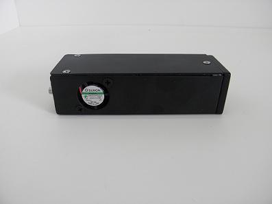
11 Picture 1 AERO CO DETECTOR 454 MODEL OWNERS/INSTALLATION MANUAL Page 11 of 25

12 6.1 RECOMMENDED INSTALLATION AREAS Typical installation areas are depicted below in Pictures 3. Picture 2 AERO-454 installed behind panel 454 MODEL OWNERS/INSTALLATION MANUAL Page 12 of 25
13 6.2 INSTALLATION INSTRUCTIONS (AERO-454) a. Install the CO Detector in accordance with Drawing # b. Install the CO Detector 2 amp circuit breaker in accordance with Drawing # Flag Note 5. It is recommended that the circuit breaker be installed on the Essential or Avionics Buss that is not subject to emergency electrical load shedding. Placard or engrave the circuit breaker as CO DETECT in accordance with Flag Note 11. c. Wire the CO Detector installation in accordance with drawing # PIN FUNCTION 1 Power Wire V (for the AERO ) 3 Spare Ground 4 Remote Reset Test 5 Power Ground 6 RS-232 in (from AERO ) 7 RS-232 out 8 RS-232 in 9 Cabin Pressure Relay CO DETECTOR CONNECTOR NINE PIN PINOUT B (Bluetooth) PIN FUNCTION 1 Power Wire 2 CO Alert Relay 3 Spare Ground 4 Remote Reset Test 5 Power Ground Ohm Audio Tone 7 RS-232 out 8 RS-232 in 9 Cabin Pressure Relay Observe the following items: The installation of wiring in accordance with Flag Note 10. Connect Pin 1 to +14 VDC or to +28 VDC power as applicable to the installation aircraft and the CO Detector voltage rating. Ground power return wire (Pin 5) to suitable aircraft structure ground near circuit breaker panel. 454 MODEL OWNERS/INSTALLATION MANUAL Page 13 of 25
14 6.2.1 INSTALLATION CHECKS (454) a. With the CO Detector disconnected from the aircraft harness, conduct a continuity check of the added aircraft wiring. b. Turn ON the aircraft Battery Switch. Close the CO DETECT circuit breaker and measure aircraft voltage between pins 1 and 5 of the CO Detector connector. Pull the CO DETECT circuit breaker. Verify the voltage between pins 1 and 5 is OFF. c. Close the CO DETECT KEEP ALIVE circuit breaker and measure aircraft voltage between pins 9 and 5 of the CO Detector connector. Turn aircraft Battery switch OFF. Measure aircraft voltage between pins 9 and 5 of the CO Detector connector. Pull the CO DETECT KEEP ALIVE circuit breaker. Verify the voltage between pins 9 and 5 is OFF. d. Connect the CO Detector connector to the aircraft harness. Turn aircraft Battery Switch ON. Close CO DETECT circuit breaker. e. Verify the unit can be shut off with the CO DETECT circuit breaker. a. Determine the moment arm for the installed CO Detector location and record in aircraft weight and balance manual. CO Detector weight is 4 oz. 7.0 GENERAL FEATURES OF THE AERO CO detector from PPM - Cabin Temperature - Cabin Pressure - Reminder to check SPO2 periodically based on cabin altitude (When or AERO 901 are installed) - Tone generator for headsets - Relay to CO and Cabin pressure - Inside temperature 454 MODEL OWNERS/INSTALLATION MANUAL Page 14 of 25
15 8.0 SELF TEST SEQUENCE AT STARTUP When the airplane master battery switch is selected ON, the 454 Detector goes through a self-test routine. The self-test checks for functionality of critical components such as the CO sensor, temperature sensor, pressure sensor, and integrity of the system and remote display will remain off if everything working properly. The RS232 MFD will show no CO on the CO Detector page. 9.0 SELF TEST SEQUENCE AT STARTUP WITH INSTALLATION OF AERO-454 WITH AERO-55 If the Aero-454 is installed to display on the Aero Display, the following test sequence should be shown at startup: The screen will show the CO Guardian software version along with two beeps, as shown on pictures 5 & 6, at the same time the amber light will flash twice, and then a third beep along with the red light flashing twice as well. After this the display will show the stand by screen CO LEVEL NORMAL, as seen on Picture 7. Picture 5 Picture 6 Picture MODEL OWNERS/INSTALLATION MANUAL Page 15 of 25


16 10.0 FUNCIONALITY TEST AND BLUETOOTH PARING The AERO-454 is also designed to display on the aircraft s MFD. The display page on the MFD depends on the MFD manufacturer. Please see pictures 8, 9 (for the SPO2 and Hearth rate data only), and 10 (for CO Level indication) for an example. Picture 8 As seen on the Grand Rapids Picture 9 As seen on the Advanced Flight Systems 454 MODEL OWNERS/INSTALLATION MANUAL Page 16 of 25
 display are installed along with the 455")


17 Picture 10 As seen on the MVP-50 When both the AERO-454 (Picture 1) and the AERO-55 (Picture 12) display are installed along with the 455 (Picture 11), place a finger in the AERO-455 (picture 11) and hold it for about 10 seconds, readings of the SPO2 (blood lever saturation percentage) and HR (hearth rate) will be displayed on the AERO-55 as shown on Picture 12. Picture 11 Picture MODEL OWNERS/INSTALLATION MANUAL Page 17 of 25
 Bluetooth pulse oximeter for wireless functions.")
18 Picture 13AERO-901 Bluetooth pulse oximeter B is equipped with Bluetooth capabilities - Bluetooth Paring. The AERO B is equipped with a Bluetooth module to interface with the AERO 901 (optional) Bluetooth pulse oximeter for wireless functions. There are several options to pair the AERO 454 CO Detector to the AERO 901 Bluetooth pulse oximeter. Option 1. Using the AERO 901 and the 454 by themselves. Hold open the AERO 901 while turning on the power for the AERO 454, the unit will pair within one minute. The AERO 901 data will be shown on the MFD. Option 2. Using MFD from other manufacturers to pair the AERO 901. Some MFD can send paring request via panel mounted buttons once pressed the 454 will go into paring mode and the data from the NONIN Bluetooth pulse oximeter (AERO 901) will be shown on the MFD. See our website or the MFD installation manual for the latest updates. Option 3. Using the B along with the AERO 901, and AERO display unit. Same procedure as Option 1 but data will be displayed on AERO display unit, as seen on picture MODEL OWNERS/INSTALLATION MANUAL Page 18 of 25
 PPM 10-50 Display only No alarm 50 70 04 minutes Alarm mode 70-100 03 minutes Alarm mode 200 02 minutes Alarm")
19 And for the CO Level display please look at Picture 14. Picture 14 Aero 55 Displaying Carbon Monoxide level in parts per million (PPM) CO LEVEL ALARM ACTIVATION CO level alarm activated after: in PPM (Parts per million) PPM Display only No alarm minutes Alarm mode minutes Alarm mode minutes Alarm mode minutes Alarm mode > seconds Alarm mode 12.0 EMERGENCY PROCEDURES Shut off the heater, air conditioning or any other opening to the engine compartment. Open a fresh air source immediately. Don't smoke. Use 100% oxygen, if possible. Land as soon as conditions permit. Be sure the source of the contamination is corrected before further flight. 454 MODEL OWNERS/INSTALLATION MANUAL Page 19 of 25

20 NOTE: The alert message will stay on until the CO level goes below 50 parts per million (PPM) by volume of carbon monoxide concentration. SEE MFD manual if the ALERT display is integrated with the Manufacturers MFD. DO not recycle the unit through the circuit breaker. A three-minute delay is required for the CO sensor to stabilize after each power-up in the 454 unit ALARM INDICATOR Relevant alert messages will display on multi-function display like (G1000, GNS480, EI- 50 and others). The RS-232 Data Buss option is currently available on numerous MFD units. The RS- 232 data buss output will couple CO Detector status information to electronic display systems with RS-232 input capability. See Multi-Function display manufacturers Installation Manual for interface guidance. The CO ALERT can be reset through the RS-232 interface provided the Multi-Function system contains the reset capability. If the AERO is installed to display on the AERO please refer to picture 15 to see how the AERO-55 will show the Amber light when the level concentration of CO in the cabin reaches above 50 PPM for more than 3 minutes. At the moment the amber alarm goes off, you will hear three short beeps every second. Use the RST button to shutoff the AUDIO alarm only. The amber light will go away until the CO concentration in the cabin disperses. Please look at paragraph 11 for more info. Picture 15 Amber alert light ON 454 MODEL OWNERS/INSTALLATION MANUAL Page 20 of 25
21 14.0 CARBON MONOXIDE LEVEL INDICATION Aero-454 can detect Carbon Monoxide from as low as 10 PPM. Aero-454 will trigger an alarm for CO long before the pilot/passengers can be affected by exposure to CO. The effect of CO level on the human body is linked to the duration of exposure to CO. Our units are designed to set off CO alarms in progressively shorter durations as the concentration of CO increases. The intention is to prevent a false alarm when the CO level poses no danger, but at the same time ensure full protection when the level starts becoming dangerous. NOTE: Aero-454 IS design to comply with FAR (a) and SAE Standard AS 412B HOW THE AERO-454 PROTECTS YOU AGAINST CO POISONING The CO display page on the MFD shows the CO level in PPM (Parts per million). The Aero-454 can display CO from 10 PPM to 999 PPM. (For any level above 999 PPM, the display will register only 999). The alarm will sound within 5 minutes if the CO level stays above 75 +/- 5 PPM. If the CO level rises above 400 PPM, the alarm will trigger instantly. (However, if the level reaches 400 PPM or above inside the cabin, it will still take a few seconds for the CO to reach the sensor inside the unit. Therefore it may take a few additional seconds for the unit to set off the CO alarm) TECHNICAL SPECIFICATIONS - Power supply: V DC - Power consumption: 2 W - Current drawn: 300 milli-amps - Fuse: Use GMI type, fast acting fuse 2A 250V - Temperature range: -20C to +65C - Humidity range: 10-90% RH (Non condensing) - Sensor calibration: Each unit calibrated at 75 PPM - Weight of the unit is approximately 4 oz. 454 MODEL OWNERS/INSTALLATION MANUAL Page 21 of 25
22 17.0 MAINTENANCE INSTRUCTIONS The carbon monoxide detector and associated equipment consist of certain parts, which do not require periodic scheduled servicing or periodic scheduled preventive maintenance. At every power up the system will go through a self-diagnostic check. WARNING: If all Models show a flashing remote Amber light every 4 seconds, return the unit to CO Guardian for repair or replacement. See MFG Manual if Remote light is displayed on the MFD. Field repair or service is allowable on all of the installed system components except for the CO Detector Indicator itself. The CO Detector must be returned to CO Guardian, LLC for all service. The aircraft wiring harness, circuit breaker shall be included maintenance instructions for general visual inspections for system integrity, installation security, corrosion and chaffing. 454 MODEL OWNERS/INSTALLATION MANUAL Page 22 of 25
23 18.0 CARBON MONOXIDE DETECTOR SCHEDULED MAINTENANCE Scheduled Maintenance Program tasks to be added to the aircraft operator's appropriate airplane maintenance program are as follows: MAINTENANCE TASK INTERVAL a. Recommended Periodic Scheduled Servicing Tasks: None Required. b. Recommended Periodic Scheduled Preventative Maintenance test/checks to determine system condition and/or latent failures: Note: Be sure the vent on the faceplate is free of obstructions. Any failures of the system are evident to the pilot through a flashing remote Amber light approximately every 4 seconds. c. Recommended Periodic Inspections: None Required. d. Recommended Periodic Structural Inspections None Required. Each time the unit is turned ON. e. Required CO Sensor replacement and calibration. At end of Service Life (Reference Par. 2.0) NOTE The unit must be returned to the manufacturer for sensor replacement and recalibration at the end of the unit service life. NO FIELD SERVICE OR OVERHAUL OF MODELS IS AUTHORIZED WEIGHT AND BALANCE / EQUIPMENT LIST The Aero 454 s CO Detector installation weighs 4 oz. Reference the aircraft weight and balance manual for moment arm. 454 MODEL OWNERS/INSTALLATION MANUAL Page 23 of 25
24 20.0 LIMITATIONS The AERO-454 CO Detector may not replace any existing instrument or indicator required by the type design or operating limits PERFORMANCE No Change 22.0 UNIT FAILURE INDICATION: A failure of the CO Sensor, Temperature Sensor, or the Micro-controller will result in the following failure indications: NOTE: SEE MFG manual if the fault data is integrated with the MFG MFD for fault analysis. If unit 454 is installed with the AERO display unit, the 55 unit will display CO SENSOR FAIL on its screen. In case of a failure indication, attempt to clear the failure condition by resetting the CO Detector. Should the failure condition continue, remove the CO Detector power by pulling the CO Detector circuit breaker. 454 MODEL OWNERS/INSTALLATION MANUAL Page 24 of 25
25 23.0 Warranty WARRANTY COVERAGE: CO GUARDIAN LLC. WARRANTS TO THE ORIGINAL CONSUMER PURCHASER, THAT THIS DETECTOR WILL BE FREE OF DEFECTS IN MATERIAL AND WORKMANSHIP FOR A PERIOD OF ONE (1) YEAR FROM DATE OF PURCHASE. THE MANUFACTURER'S LIABILITY HEREUNDER IS LIMITED TO REPLACEMENT OF THE PRODUCT, REPAIR OF THE PRODUCT OR REPLACEMENT OF THE PRODUCT WITH A REPAIRED PRODUCT AT THE DISCRETION OF THE MANUFACTURER. THIS WARRANTY IS VOID IF THE PRODUCT HAS BEEN DAMAGED BY ACCIDENT, UNREASONABLE USE, NEGLECT, TAMPERING OR OTHER CAUSES NOT ARISING FROM DEFECTS IN MATERIAL OR WORKMANSHIP. THIS WARRANTY EXTENDS TO THE ORIGINAL CONSUMER PURCHASER OF THE PRODUCT ONLY. Warranty Disclaimers: Any implied warranties arising out of this sale, including but not limited to the implied warranties of description, merchantability and fitness for a particular purpose, are limited in duration to the above warranty period. In no event shall the Manufacturer be liable for loss of use of this product or for any indirect, special, incidental or consequential damages, or costs, or expenses incurred by the consumer or any other user of this product, whether due to a breach of contract, negligence, strict liability in tort or otherwise. The manufacturer shall have no liability for any personal injury, property damage or any special, incidental, contingent or consequential damage of any kind resulting from gas leakage, fire or explosion. Some states do not allow limitations on how long an implied warranty lasts, so the above limitation may not apply to you. Some states do not allow the exclusion or limitation of consequential or incidental damages, so the above limitations or exclusions may not apply to you. Legal Remedies: This warranty gives you specific legal rights and you may also have other rights that vary from state to state. Warranty Performance: During the above warranty period, your product will be replaced with a comparable product if the defective product is returned, postage prepaid, to CO Guardian, Customer Service Department, 1951 East Airport Drive, Tucson, AZ 85706, together with proof of purchase date. Please include a note describing the problem when you return the unit. The replacement product will be in warranty for the remainder of the original warranty period or for six months whichever is longer. Other than the cost of postage, no charge will be made for replacement of the defective product. Important: Do not attempt to open unit. If unit is opened, warranty will be void. Your Carbon Monoxide Alarm is not a substitute for property, disability, life or other insurance of any kind. Appropriate insurance coverage is your responsibility. Consult your insurance agent. NOTE The warranty will be void if the unit is opened or tampered with 454 MODEL OWNERS/INSTALLATION MANUAL Page 25 of 25
CO Guardian LLC Document: E. AIRPORT DRIVE Date: 11/15/05 OWNERS MANUAL
 OWNERS MANUAL CARBON MONOXIDE DETECTOR MODELS Panel mount and Remote Detectors (R) (353 and 353R) 353 FAMILY MODEL OWNERS/INSTALLATION MANUAL Page 1 of 22 LOG OF REVISIONS REV NO. PAGE NO. DATE DESCRIPTION
OWNERS MANUAL. CARBON MONOXIDE DETECTOR MODELS Panel Mount & Remote Detectors (R) Guardian Avionics 1951 E. AIRPORT DRIVE TUCSON, AZ.
 Guardian Avionics 1951 E. AIRPORT DRIVE TUCSON, AZ.") OWNERS MANUAL CARBON MONOXIDE DETECTOR MODELS Panel Mount & Remote Detectors (R) (353-101 and 353-201) 353 FAMILY MODEL OWNERS/INSTALLATION MANUAL Page 1 of 22 LOG OF REVISIONS REV NO. PAGE NO. DATE DESCRIPTION
OWNERS MANUAL CARBON MONOXIDE DETECTOR MODELS Panel Mount & Remote Detectors (R) (353-101 and 353-201) 353 FAMILY MODEL OWNERS/INSTALLATION MANUAL Page 1 of 22 LOG OF REVISIONS REV NO. PAGE NO. DATE DESCRIPTION
CO Guardian LLC Document No E. AIRPORT DRIVE Date: 08/25/10 OWNERS MANUAL
 OWNERS MANUAL PULSE OXIMETER AND CARBON MONOXIDE DETECTOR MODEL AERO-455 Rev. B 455 MODEL OWNERS/INSTALLATION MANUAL Page 1 of 21 LOG OF REVISIONS REV NO. PAGE NO. DATE DESCRIPTION APPROVED A 1 thru 20
CO Guardian LLC Document No E. AIRPORT DRIVE Date: TUCSON, AZ CO Guardian LLC 1951 E. Airport Dr.
 1951 E. AIRPORT DRIVE Date: 8-20-2004 CO Guardian LLC 1951 E. Airport Dr. Tucson, AZ 85706 OWNERS MANUAL CARBON MONOXIDE DETECTOR MODEL 452-201 REMOTE UNIT MODEL 452-201 OWNERS MANUAL Page 1 of 22 INTENTIONALLY
Document No
 CO Guardian LLC 1951 E. Airport Dr. Tucson, AZ 85706 CARBON MONOXIDE DETECTOR MODEL 452 INSTALLATION AND OPERATIONAL MANUAL Document No. 01-2510-02 MODEL 452 INSTALLATION AND OPERATIONAL MANUAL Page 1
OWNERS MANUAL MODEL 451 (-101 & -201)
") OWNERS MANUAL MODEL 451 (-101 & -201) Guardian Avionics CO Guardian, LLC. 1951 E Airport Drive Tucson, AZ 85756 Phone: 520-889-1177 8:00 am - 5:00 pm MST support@guardianavionics.com 2 Table of Contents
OWNERS MANUAL MODEL 451 (-101 & -201) Guardian Avionics CO Guardian, LLC. 1951 E Airport Drive Tucson, AZ 85756 Phone: 520-889-1177 8:00 am - 5:00 pm MST support@guardianavionics.com 2 Table of Contents
User s Manual For Model Aero-551 (Rev. Orig.)
") User s Manual For Model Aero-551 (Rev. Orig.) Document: 551-100 REV A LOG OF REVISIONS REV NO. PAGE NO. DATE DESCRIPTION APPROVED Orig. 1 thru 5 12/4/06 Initial Release ASH VIJ A 2 and 3 10/22/06 Deleted
User s Manual For Model Aero-551 (Rev. Orig.) Document: 551-100 REV A LOG OF REVISIONS REV NO. PAGE NO. DATE DESCRIPTION APPROVED Orig. 1 thru 5 12/4/06 Initial Release ASH VIJ A 2 and 3 10/22/06 Deleted
CO Guardian LLC Document # E. AIRPORT DRIVE Date: 10/17/11 TUCSON, AZ REV C. OWNERS MANUAL
 OWNERS MANUAL PULSE OXIMETER AND CARBON MONOXIDE DETECTOR MODEL AERO-455 Rev. C. 455 MODEL OWNERS/INSTALLATION MANUAL Page 1 of 24 LOG OF REVISIONS REV NO. PAGE NO. DATE DESCRIPTION APPROVED A 1 thru 24
Owner s Manual For Model Aero-553 (Rev. A.)
") 1951 E. AIRPORT DRIVE Date: 11-16-10 Owner s Manual For Model Aero-553 (Rev. A.) Document: 553-553 MODEL OWNERS/INSTALLATION MANUAL Page 1 of 30 1951 E. AIRPORT DRIVE Date: 11-16-10 INTENIONALLY LEFT BLANK
1951 E. AIRPORT DRIVE Date: 11-16-10 Owner s Manual For Model Aero-553 (Rev. A.) Document: 553-553 MODEL OWNERS/INSTALLATION MANUAL Page 1 of 30 1951 E. AIRPORT DRIVE Date: 11-16-10 INTENIONALLY LEFT BLANK
OPEARATING GUIDELINES FOR AERO-252 (Pages 1 to 3 contain general information on CO Guardian. Pages 4 to 6 contain information specific to Aero 252)
") OPEARATING GUIDELINES FOR AERO-252 (Pages 1 to 3 contain general information on CO Guardian. Pages 4 to 6 contain information specific to Aero 252) What is Carbon Monoxide? Carbon Monoxide (CO) is a colorless,
OPEARATING GUIDELINES FOR AERO-252 (Pages 1 to 3 contain general information on CO Guardian. Pages 4 to 6 contain information specific to Aero 252) What is Carbon Monoxide? Carbon Monoxide (CO) is a colorless,
INSTRUCTIONS FOR CONTINUED AIRWORTHINESS
 1951 E. Airport Dr. Tucson, AZ 85706 INSTRUCTIONS FOR CONTINUED AIRWORTHINESS CARBON MONOXIDE DETECTOR MODEL 452 INSTALLATION FOR CESSNA MODEL 172 AIRCRAFT STC NO: ST9261LA-A RECORD OF REVISIONS No. Revision
INSTALLATION MANUAL AND OPERATING INSTRUCTIONS
 INSTALLATION MANUAL AND OPERATING INSTRUCTIONS MD41-1000 SERIES TERRAIN AWARENESS ANNUNCIATION CONTROL UNIT MD41-1028 28vdc Horizontal Mount MD41-1038 28vdc Vertical Mount (shown on page 12) MD41-1028(5V)
INSTALLATION MANUAL AND OPERATING INSTRUCTIONS MD SERIES TERRAIN AWARENESS ANNUNCIATION CONTROL UNIT FOR GARMIN TAWS SYSTEMS
 INSTALLATION MANUAL AND OPERATING INSTRUCTIONS MD41-1000 SERIES TERRAIN AWARENESS ANNUNCIATION CONTROL UNIT FOR GARMIN TAWS SYSTEMS MD41-1028 28vdc Horizontal Mount MD41-1038 28vdc Vertical Mount (shown
INSTALLATION MANUAL AND OPERATING INSTRUCTIONS
 INSTALLATION MANUAL AND OPERATING INSTRUCTIONS MD41-1200 SERIES TERRAIN AWARENESS ANNUNCIATION CONTROL UNIT for SANDEL ST3400 TAWS MD41-1248 28vdc Horizontal Mount MD41-1258 28vdc Vertical Mount (shown
10-3 Rev. A
 Owner s Manual 65X and 85X Document P/N 10-3 OWNER S MANUAL CO Guardian LLC FMS 65X and 85X Aircraft data on your tablet and in the cloud Carbon monoxide (CO) is a colorless, odorless, and tasteless gas
A D U ANNUNCIATOR DIM / TEST UNIT INSTALLATION MANUAL DESCRIPTION AND THEORY OF OPERATION
 AVIONICS ENGINEERING SERVICES A D U ANNUNCIATOR DIM / TEST UNIT INSTALLATION MANUAL DESCRIPTION AND THEORY OF OPERATION Document No. 92-0003-06 REV C May 31, 2000 INSTALLATION MANUAL DESCRIPTION AND THEORY
INSTALLATION MANUAL AND OPERATING INSTRUCTIONS
 INSTALLATION MANUAL AND OPERATING INSTRUCTIONS MD41-( ) Series GPS Annunciation Unit For Garmin GNS and GTN Systems MD41-1484W 14VDC Horizontal Mount MD41-1488W 28VDC Horizontal Mount MD41-1494W 14VDC
INSTALLATION MANUAL AND OPERATING INSTRUCTIONS
 INSTALLATION MANUAL AND OPERATING INSTRUCTIONS MD41-104X/MD41-105X Series Helicopter Terrain Awareness Warning System Annunciation Control Unit For Garmin 4XXW/5XXW Systems MD41-1048 28vdc Horizontal Mount
INSTALLATION MANUAL AND OPERATING INSTRUCTIONS
 INSTALLATION MANUAL AND OPERATING INSTRUCTIONS MD41-( ) Series GPS Annunciation Unit For Garmin GNS 430/530 VHF Communication and Navigation Management System MD41-1484 14VDC Horizontal Mount MD41-1488
INSTALLATION MANUAL AND OPERATING INSTRUCTIONS. MD41-151X Series Annunciation Control Unit For Garmin GPS Systems
 INSTALLATION MANUAL AND OPERATING INSTRUCTIONS MD41-151X Series Annunciation Control Unit For Garmin GPS Systems MD41-1510 28vdc Horizontal Mount MD41-1511 28vdc Vertical Mount MD41-1512 14vdc Horizontal
INSTRUCTIONS FOR CONTINUED AIRWORTHINESS
 Doc. # ICA-55 REV ORig. 1951 E. Airport Dr. Tucson, AZ 85756 Document No. ICA-55-301 INSTRUCTIONS FOR CONTINUED AIRWORTHINESS DISPLAY MODEL 55 INSTALLATION RECORD OF REVISIONS No. Revision Inserted Date
GAS MONITOR Model Model
 Sierra Monitor Corporation 1991 Tarob Court, Milpitas, CA 95035 (408) 262-6611 (800) 727-4377 (408) 262-9042 - Fax E-mail: sierra@sierramonitor.com Web Site: www.sierramonitor.com GAS MONITOR Model 2350-00
Falcon-II Next Generation, Air Quality Monitor CO2 & Temperature
 Critical Environment Technologies Canada Inc. Falcon-II Next Generation, Air Quality Monitor CO2 & Temperature OPERATION MANUAL REV: A JUNE-2-2008 #145, 7391 Vantage Way Delta, BC V4G 1M3 Canada Phone:
THL2. Temperature/Humidity USB Datalogger INSTRUCTION MANUAL
 The THL2 is compatible with computers using Windows 2000, XP, Vista, Windows 7 and Windows 8. INSTRUCTION MANUAL 2 THL2 1-800-547-5740 Fax: (503) 643-6322 www.ueitest.com email: info@ueitest.com Temperature/Humidity
Spa Control System OWNER S MANUAL
 LIMITED WARRANTY ONE YEAR LIMITED WARRANTY: UNITED SPAS, INC. warrants, to the original purchaser, the Spa Equipment against defects in materials or workmanship for a period of one year from date of purchase.
INSTALLATION MANUAL AND OPERATING INSTRUCTIONS
 INSTALLATION MANUAL AND OPERATING INSTRUCTIONS MD200-2XX SERIES COURSE DEVIATION INDICATOR MFG. P/N: MD200-202/-202(5V) MFG. P/N: MD200-203/-203(5V) MFG. P/N: MD200-206/-206(5V) MFG. P/N: MD200-207/-207(5V)
Test Equipment Depot Washington Street Melrose, MA TestEquipmentDepot.com INSTRUCTION MANUAL THL1
 Test Equipment Depot - 800.517.8431-99 Washington Street Melrose, MA 02176 - TestEquipmentDepot.com INSTRUCTION MANUAL THL1 Introduction C o n t rols and Indicators Use the UEi THL1 to log temperature
MARC70 Installation Manual
 MARC70 Installation Manual SA 3/L/NVG SA 15 SA 24 SR 34 SR 54 SR 64 SR 263 SR 342 SR 623 SRU 1 SRU 5 SRU 10 3700 Osuna Rd. NE, Suite 711 Albuquerque, NM 87109 505.341.2930 www.sandia.aero 305147-00 This
MODEL HS115-3, HS115-4 & HS115-5 WIRING DIAGRAM ADDENDUM
 TJERNLUND PRODUCTS, INC. 1601 Ninth Street White Bear Lake, MN 55110-6794 PHONE (800) 255-4208 (651) 426-2993 FAX (651) 426-9547 Visit our web site www.tjernlund.com MODEL HS115-3, HS115-4 & HS115-5 WIRING
MGC Dock User s Manual
 Operator s Manual Contents Warnings Statements/Avertisseement... 3 READ FIRST BEFORE OPERATION... 3 Basic Operation... 4 Clip Dock Components... 4 LEDs... 4 Operation... 5 Turning the Clip Dock On and
GASGUARD NH 3. Ammonia Sensor OPERATING & INSTALLATION MANUAL
 GASGUARD NH 3 Ammonia Sensor OPERATING & INSTALLATION MANUAL Operating and Installation Manual 2 Table of Contents GasGuard NH 3 Operating and Instruction Manual General description. 4 Installation.. 4
GASGUARD Cl 2. Chlorine Sensor OPERATING & INSTALLATION MANUAL
 GASGUARD Cl 2 Chlorine Sensor OPERATING & INSTALLATION MANUAL Operating and Installation Manual 2 Table of Contents GasGuard Cl 2 Operating and Instruction Manual General description. 4 Installation..
GG-CO-EXP CARBON MONOXIDE SENSOR. Installation and Operation Manual
 GG-CO-EXP CARBON MONOXIDE SENSOR Installation and Operation Manual 2 GG-CO-EXP Warning Use this product only in the manner described in this manual. If the equipment is used in a manner not specified by
Carbon Monoxide (CO) Detecting Ventilation Fan Controller Model COSTAR 24VC-e Single Relay
 Detecting Ventilation Fan Controller Model COSTAR 24VC-e Single Relay") Carbon Monoxide (CO) Detecting Ventilation Fan Controller Model COSTAR 24VC-e Single Relay Part No. 905-0000-09 Replacement Sensor Module is Part Number 905-0001-09 1. INTRODUCTION Your COSTAR 24VC-e carbon
Carbon Monoxide (CO) Detecting Ventilation Fan Controller Model COSTAR 24VC-e Single Relay Part No. 905-0000-09 Replacement Sensor Module is Part Number 905-0001-09 1. INTRODUCTION Your COSTAR 24VC-e carbon
GG-H2S HYDROGEN SULFIDE GAS SENSOR. Installation and Operation Manual
 GG-H2S HYDROGEN SULFIDE GAS SENSOR Installation and Operation Manual 2 GG-H2S Warning Use this product only in the manner described in this manual. If the equipment is used in a manner not specified by
OI-2400-DOCK Multi Gas Docking Station. Operation Manual trevision 2.2w
 OI-2400-DOCK Multi Gas Docking Station Operation Manual trevision 2.2w Table of Contents Introduction... 3 Warnings Statements/Avertisseement... 4 Basic Operation... 5 OI-2400-DOCK Components... 5 LEDs...
GASGUARD SO2 Sulfur Dioxide Sensor OPERATING & INSTALLATION MANUAL
 GASGUARD SO2 Sulfur Dioxide Sensor OPERATING & INSTALLATION MANUAL Operating and Installation Manual Warning Use this product only in the manner described in this manual. If the equipment is used in a
Operator s Manual. IP-100 Immersion Probe Cooler
 Operator s Manual IP-100 Immersion Probe Cooler 110-810 04.27.11 Table of Contents Introduction... 3 General Information... 3 General Safety Information... 3 Safety Recommendations... 4 Unpacking Your
GG-NO2 NITROGEN DIOXIDE GAS SENSOR. Installation and Operation Manual
 GG-NO2 NITROGEN DIOXIDE GAS SENSOR Installation and Operation Manual 2 GG-NO2 Warning Use this product only in the manner described in this manual. If the equipment is used in a manner not specified by
INSTALLATION AND OPERATING INSTRUCTIONS FOR THE VEHICLE-MOUNTED RADIATION DETECTION SYSTEM
 INSTALLATION AND OPERATING INSTRUCTIONS FOR THE VEHICLE-MOUNTED RADIATION DETECTION SYSTEM D-tect Systems 11814 South Election Road, Suite 200 Draper, UT 84020 www.dtectsystems.com 1 Introduction The mini
DWA2000. WAAS Annunciator. Installation and Operations Manual. Rev 1.0 August 2014
 DWA2000 WAAS Annunciator Installation and Operations Manual Rev 1.0 August 2014 Deklin Technologies Inc 413 Childe Harolds Lane Brentwood, TN 37027 Tel: (615) 819-0800 Fax: (615) 819-0801 www.deklintech.com
GASGUARD H 2-1% Hydrogen Sensor OPERATING & INSTALLATION MANUAL
 GASGUARD H 2-1% Hydrogen Sensor OPERATING & INSTALLATION MANUAL 2 Table of Contents GasGuard H 2-1% General description. 4 Installation.. 4 Locating the sensor. 4 Installation guidelines 5 Wiring.. 6 Operation..
GASGUARD O 2. Oxygen Sensor OPERATING & INSTALLATION MANUAL
 GASGUARD O 2 Oxygen Sensor OPERATING & INSTALLATION MANUAL 2 Table of Contents General description. 4 Installation.. 4 Locating the sensor. 4 Installation guidelines 5 Wiring.. 6 Operation.. 7 Start-up...
CIRRUS AIRPLANE MAINTENANCE MANUAL
 INDICATING/RECORDING SYSTEMS 1. DESCRIPTION This section describes the Indicating/Recording Systems which consists of an Annunciator Panel and related sensors and switches. A. Annunciator Panel - Serials
VX SERIES Wireless Thermostat with Occupancy Sensor
 VX SERIES Wireless Thermostat with Occupancy Sensor INSTRUCTION MANUAL Table of Contents Thermostat Installation... 7 Installing the Wireless Control Card...8 Mounting the thermostat to the wall...9 Thermostat
RK-05 Carbon Monoxide Detector Operator s Manual
 65-2433RK-05 Carbon Monoxide Detector Operator s Manual Part Number: 71-0189RK Revision: 0 Released: 5/17/11 RKI Instruments, Inc. www.rkiinstruments.com WARNING Read and understand this instruction manual
User Guide. for the Beacon ProActTM 200 System
 TM User Guide for the Beacon ProActTM 200 System BEACON recommends that this product, like all sump pumprelated products, be installed by or under the supervision of a professional plumbing contractor.
Single Gas Clip and SGC Plus User s Manual Rev 2.1 READ FIRST BEFORE OPERATION WARNING STATEMENTS / AVERTISSEMENT Activating tthe detector for the
 Single Gas Clip and SGC Plus User s Manual Rev 2.1 READ FIRST BEFORE OPERATION Gas Clip Technologies (GCT) Single Gas Clip and SGC Plus detectors are personal safety devices designed to detect the presence
MGC Dock User s Manual
 User s Manual Contents Warnings Statements/Avertisseement... 3 READ FIRST BEFORE OPERATION... 3 Description... 4 Basic Operation... 5 Clip Dock Components... 5 LEDs... 5 User Operation... 6 Turning the
Macurco Single-Gas XL Series Monitor, CM-1XL Carbon Monoxide (CO), HS-1XL Hydrogen Sulfide (H2S) User Instructions
, HS-1XL Hydrogen Sulfide (H2S) User Instructions") Macurco Single-Gas XL Series Monitor, CM-1XL Carbon Monoxide (CO), HS-1XL Hydrogen Sulfide (H2S) User Instructions Important: Keep these User Instructions for reference 2 TABLE OF CONTENTS GENERAL SAFETY
Macurco Single-Gas XL Series Monitor, CM-1XL Carbon Monoxide (CO), HS-1XL Hydrogen Sulfide (H2S) User Instructions Important: Keep these User Instructions for reference 2 TABLE OF CONTENTS GENERAL SAFETY
C0-210 Carbon Monoxide Probe
 C0-210 Carbon Monoxide Probe Instruction Sheet Introduction The CO-210 Carbon Monoxide Probe (hereafter referred to as the Probe ) detects the presence of carbon monoxide (CO) and measures concentrations
GG-NH3 AMMONIA GAS SENSOR. Installation and Operation Manual
 GG-NH3 AMMONIA GAS SENSOR Installation and Operation Manual 2 GG-NH3 Warning Use this product only in the manner described in this manual. If the equipment is used in a manner not specified by Calibration
BACKUP BATTERY INSTALLATION INSTRUCTIONS
 www.tiltlights.com BACKUP INSTRUCTIONS A Lauren International Company www.laurenillumination.com 855 440 8458 LdPE7-2014 SELf-TESTINg EmERgENCY LEd driver RATINGS: Input: 100-277 VAC 50 or 60 Hz Output:
WARNING AND TEST MASTER WARNING AND MASTER CAUTION SYSTEMS
 WARNING AND TEST MASTER WARNING AND MASTER CAUTION SYSTEMS The Warning and Caution systems are discussed here in conjunction with the Warning and Test Systems, primarily to cover the procedures for testing
GASGUARD H2S EXP. Hydrogen Sulfide Sensor OPERATING & INSTALLATION MANUAL
 GASGUARD H2S EXP Hydrogen Sulfide Sensor OPERATING & INSTALLATION MANUAL Operating and Installation Manual Warning Use this product only in the manner described in this manual. If the equipment is used
DWA2000. WAAS Annunciator. Installation and Operations Manual. Rev 1.1 December 2014
 DWA2000 WAAS Annunciator Installation and Operations Manual Rev 1.1 December 2014 Deklin Technologies Inc 413 Childe Harolds Lane Brentwood, TN 37027 Tel: (615) 819-0800 Fax: (615) 819-0801 www.deklintech.com
GASGUARD NH 3 2% Ammonia Sensor OPERATING & INSTALLATION MANUAL
 GASGUARD NH 3 2% Ammonia Sensor OPERATING & INSTALLATION MANUAL 2 Table of Contents GasGuard NH 3 2% General description. 4 Installation.. 4 Locating the sensor. 4 Installation guidelines 5 Wiring.. 6
MaxLite LED MICRO-T PANEL
 ` Installation Instructions General Safety Information To reduce the risk of death, personal injury or property damage from fire, electric shock, falling parts, cuts/abrasions, and other hazards read all
Controllers. Instruction Manual WARNING
 Controllers Instruction Manual WARNING THIS MANUAL MUST BE CAREFULLY READ BY ALL INDIVIDUALS WHO HAVE OR WILL HAVE THE RESPONSIBILITY FOR INSTALLING, USING OR SERVICING THIS PRODUCT. Like any piece of
GASGUARD LEL 3 OPERATING & INSTALLATION MANUAL
 GASGUARD LEL 3 Ammonia Sensor OPERATING & INSTALLATION MANUAL GasGuard LEL 3 Operating and Installation Manual 2 Table of Contents 3GasGuard LEL Operating and Instruction Manual General description. 4
GASGUARD VENT LINE3. Ammonia Sensor OPERATING & INSTALLATION MANUAL
 GASGUARD VENT LINE3 Ammonia Sensor OPERATING & INSTALLATION MANUAL Operating and Installation Manual Warning Use this product only in the manner described in this manual. If the equipment is used in a
NEUTRONICS MINI ID R-1234yf REFRIGERANT IDENTIFIER OPERATION MANUAL
 NEUTRONICS MINI ID R-1234yf REFRIGERANT IDENTIFIER OPERATION MANUAL 456 Creamery Way, Exton, PA 19341, USA Phone: 610.524.8800 Fax: 610.524.8807 Email: info@refrigerantid.com www.refrigerantid.com Page
Remote Aural Warning System and Summing Amplifier Installation and Operation Manual
 9800 Martel Road Lenoir City, TN 37772 www.ps-engineering.com PRD60 Remote Aural Warning System and Summing Amplifier Installation and Operation Manual Document P/N 200-160-0200 Revision 3, Sept. 2012
PAC-2750 ELECTRIC COOLING FAN CONTROLLER
 PAC-2750 ELECTRIC COOLING FAN CONTROLLER IMPORTANT NOTE: The +12V for the controller should NOT be taken from the same circuit as the Fan Power 12V as this can cause the fan to cycle on and off. Required
GG-EM ENTRANCE MONITOR. Installation and Operation Manual
 GG-EM ENTRANCE MONITOR Installation and Operation Manual 2 GG-EM Warning Use this product only in the manner described in this manual. If the equipment is used in a manner not specified by Calibration
GG-2 2-CHANNEL GAS DETECTION CONTROL PANEL. Installation and Operation Manual
 GG-2 2-CHANNEL GAS DETECTION CONTROL PANEL Installation and Operation Manual 2 GG-2 Warning Use this product only in the manner described in this manual. If the equipment is used in a manner not specified
Rev. None AUGUST 2012 MDM SERIES MODULAR MEMBRANE AIR DRYERS OPERATOR MANUAL MDM1 MDM4 MDM9 MDM13 MDM24 MDM49 MDM66 MDM106 MDM138
 7428146 Rev. None AUGUST 2012 MDM SERIES MODULAR MEMBRANE AIR DRYERS OPERATOR MANUAL MDM1 MDM4 MDM9 MDM13 MDM24 MDM49 MDM66 MDM106 MDM138 1.0 SAFETY All compressed gases, including air, can be dangerous.
READ ME FIRST DIY WIRELESS ALERT. Add-on Alert Sensor. For Swann Wireless Alert systems. Instruction Manual
 READ ME FIRST DIY WIRELESS ALERT Add-on Alert Sensor For Swann Wireless Alert systems EN Instruction Manual 2 About this Manual The content in this manual is for information purposes only and is subject
INSTALLATION. and INSTRUCTION MANUAL. for QUALITY AIR BREATHING SYSTEMS. Model ABM - 715
 INSTALLATION and INSTRUCTION MANUAL for QUALITY AIR BREATHING SYSTEMS Model ABM - 715 M A R T E C H S E R V I C E S C O M P A N Y P.O. Box 7079 OFFICE: 800-831-1525 Mazeppa, MN 55956 Fax : (507)843-4953
Carbon Monoxide (CO) Detecting Ventilation Fan Controller Model 120VC Single Relay (100/25 PPM) (200/35 PPM)
 Detecting Ventilation Fan Controller Model 120VC Single Relay (100/25 PPM) (200/35 PPM)") Carbon Monoxide (CO) Detecting Ventilation Fan Controller Model 120VC Single Relay 905-0005-01 (100/25 PPM) 905-0005-02 (200/35 PPM) 1. INTRODUCTION Your COSTAR VC carbon monoxide detecting ventilation
Carbon Monoxide (CO) Detecting Ventilation Fan Controller Model 120VC Single Relay 905-0005-01 (100/25 PPM) 905-0005-02 (200/35 PPM) 1. INTRODUCTION Your COSTAR VC carbon monoxide detecting ventilation
182T and T182T Air Conditioning System ICA Revision: Date: 17 September, 2008
 Document Number: NC-08-037 Title: 182T and T182T Air Conditioning System ICA Revision: C Date: 17 September, 2008 Name Signature Date Author Erik Pederson Signed Copy On File 9/17/08 Approved Erik Pederson
WARNING AND TEST MASTER WARNING AND MASTER CAUTION SYSTEMS
 MODEL 680 WARNING AND TEST MASTER WARNING AND MASTER CAUTION SYSTEMS The Warning and Caution systems are discussed here in conjunction with the Warning and Test Systems, primarily to cover the procedures
GASGUARDIAN Channel Controller OPERATING & INSTALLATION MANUAL
 GASGUARDIAN 2 3 2-Channel Controller OPERATING & INSTALLATION MANUAL GasGuardian 2 3 Operating and Installation Manual Table of Contents General description.... 3 Installation. 3 Locating the GasGuardian-2..
PRO-TEC SYSTEM ONE. Trailer Security Systems Model # PTS-2. Photo includes PTS-2 with optional pager unit
 PRO-TEC SYSTEM ONE Trailer Security Systems Model # PTS-2 Photo includes PTS-2 with optional pager unit Professional Technology to Pro-Tec Your Investment More helpful install information on our website
Total Connect Box. User manual
 Total Connect Box User manual 1 Congratulations on your purchase of the Honeywell Total Connect Box security system. To make the best out of your system we advise you to read this manual carefully. This
Model LP USER S MANUAL AND INSTALLATION INSTRUCTIONS
 Atwood Mobile Products LLC 1120 North Main Street Elkhart, IN 46614-3203 USA & Canada 1-866-869-3118 Internet: http://www.atwoodmobile.com Model LP USER S MANUAL AND INSTALLATION INSTRUCTIONS TESTED TO
WATCHMAN Model LBW-WATCHMAN Ammonia Leak Detector
 WATCHMAN Model LBW-WATCHMAN Ammonia Leak Detector IMPORTANT READ THIS FIRST....3 CAUTIONS... 3 AVOIDING NUISANCE ALARMS... 3 STANDARD FEATURES... 4 AVAILABLE OPTIONS... 4 PARTS DESCRIPTION... 5 FRONT PANEL
MACURCO INC. CONTROLLERS & CARBON MONOXIDE DETECTORS SS103-3A, SS103-10A SS102H, SS102HC-1 INSTALLATION & OPERATING INSTRUCTIONS
 MACURCO INC. CONTROLLERS & CARBON MONOXIDE DETECTORS SS103-3A, SS103-10A SS102H, SS102HC-1 INSTALLATION & OPERATING INSTRUCTIONS WWW.MACURCO.COM NOTE: SUGGESTED WIRE SIZE VS LENGTH OF WIRE BETWEEN EACH
Three Phase Simplex. Installation (937) Installation Instructions and Operation/Troubleshooting Manual. Installation of Floats.
 Installation Instructions and Operation/Troubleshooting Manual. Installation of Floats.") Three Phase Simplex Installation Instructions and Operation/Troubleshooting Manual This control panel must be installed and serviced by a licensed electrician in accordance with the National Electric Code
Three Phase Simplex Installation Instructions and Operation/Troubleshooting Manual This control panel must be installed and serviced by a licensed electrician in accordance with the National Electric Code
Instruction Manual WARNING
 Controllers Instruction Manual WARNING THIS MANAUL MUST BE CAREFULLY READ BY ALL INDIVIDUALS WHO HAVE OR WILL HAVE THE RESPONSIBILITY FOR INSTALLING, USING OR SERVICING THIS PRODUCT. Like any piece of
RK-02 Multi Point Detector Operator s Manual
 65-2485RK-02 Multi Point Detector Operator s Manual Part Number: 71-0237RK Revision: A Released: 11/26/14 RKI Instruments, Inc. www.rkiinstruments.com WARNING Read and understand this instruction manual
EZY SWITCH. SMS-IRR-4 System Monitor Installation Manual
 EZY SWITCH SMS-IRR-4 System Monitor Installation Manual Table of Contents COMMANDS Getting Started Setting Up Initial User 7 Adding a User 8 Removing a User 8 Adding an Administrator 8 Removing the Administrator
GG-R REFRIGERANT SENSOR. Installation and Operation Manual
 GG-R REFRIGERANT SENSOR Installation and Operation Manual 2 GG-R Warning Use this product only in the manner described in this manual. If the equipment is used in a manner not specified by Calibration
Single Gas Clip and SGC Plus User s Manual Rev 2.3
 Single Gas Clip and SGC Plus User s Manual Rev 2.3 READ BEFORE OPERATION Gas Clip Technologies (GCT) Single Gas Clip and SGC Plus detectors are personal safety devices designed to detect the presence of
INSTALLATION. and INSTRUCTION MANUAL. for QUALITY AIR BREATHING SYSTEMS. Model ABM - 700
 INSTALLATION and INSTRUCTION MANUAL for QUALITY AIR BREATHING SYSTEMS Model ABM - 700 M A R T E C H S E R V I C E S C O M P A N Y P.O. Box 7079 OFFICE: 800-831-1525 Mazeppa, MN 55956 Fax : (507)843-4953
Users Manual. LAURUS Systems, Inc. - Ph: Fax:
 Users Manual LAURUS Systems, Inc. - Ph: 410-465-5558 - Fax: 410-465-5257 - www.laurussystems.com Introduction The rad-d is a security and inspection system that detects emissions from radioactive material.
GG-VL-R REFRIGERANT VENT LINE SENSOR. Installation and Operation Manual
 GG-VL-R REFRIGERANT VENT LINE SENSOR Installation and Operation Manual 2 GG-VL-R Warning Use this product only in the manner described in this manual. If the equipment is used in a manner not specified
Users Manual. Air Velocity Meter
 923 Air Velocity Meter Users Manual PN 4024518 September 2011 2011 Fluke Corporation. All rights reserved. Printed in Taiwan. Specifications are subject to change without notice. All product names are
GG-NH3-2% AMMONIA GAS SENSOR. Installation and Operation Manual
 GG-NH3-2% AMMONIA GAS SENSOR Installation and Operation Manual 2 GG-NH3-2% Warning Use this product only in the manner described in this manual. If the equipment is used in a manner not specified by Calibration
OPERATING MANUAL. The Guardian Hand Held Security Metal Detector
 OPERATING MANUAL The Guardian Hand Held Security Metal Detector COMFORT GRIP OPERATOR DETECTION ALERTS Audio Alert High Pitch Sound Vibration Alert - Silent Operation LED Target Indicator - Red INTERFERENCE
Ambient Weather WS-26 Indoor Thermo-Hygrometer with Daily Min/Max Display User Manual
 Ambient Weather WS-26 Indoor Thermo-Hygrometer with Daily Min/Max Display User Manual Table of Contents 1 Introduction... 2 2 Getting Started... 2 Parts List... 2 3 Display Console Layout... 3 4 Display
CO2 RESPONDER Portable Carbon Dioxide Detector QUICK REFERENCE GUIDE
 CO2 RESPONDER Portable Carbon Dioxide Detector QUICK REFERENCE GUIDE GasAlertMicro 5 IR from Refer to for more details. Manual provided on CD with unit at time of purchase 2 Table of Contents Getting Started.
INSTRUCTION MANUAL TS21. 2 Heating and 1 Cooling
 INSTRUCTION MANUAL TS21 2 Heating and 1 Cooling WELCOME TO Flexible applications - Universal and easy to install in residential or commercial environments. Advanced features - Precision electronics provide
INSTALLATION & OPERATION MANUAL
 INSTALLATION & OPERATION MANUAL Model TME- * * Balance of model number is determined by customer specifi ed limits and Setbacks. AUTOMATIC SETBACK THERMOSTAT LIGHT SENSING OR CONTACT CLOSURE FOR LOW VOLTAGE
Single Phase Simplex SXL21=3, SXL24=3, SXH21=3, and SXH24=3
 Single Phase Simplex SXL21=3, SXL24=3, SXH21=3, and SXH24=3 Manufactured by SJE-Rhombus Installation Instructions and Operation/Troubleshooting Manual 7000 Apple Tree Avenue Bergen, New York 14416 Phone:
Automatic Phone-Out Home Monitoring Systems
 Automatic Phone-Out Home Monitoring Systems Power Outage, Freeze and Flood Alarm Product Description Model Number: THP201 These monitoring systems are intended to monitor homes, cabins, and other premises
460H INSTALLATION & OPERATION MANUAL REMOTE STROBE POWER SUPPLY IMPORTANT: 460H TM REMOTE STROBE POWER SUPPLY
 INSTALLATION & OPERATION MANUAL 460H TM REMOTE STROBE POWER SUPPLY 460H REMOTE STROBE POWER SUPPLY Contents: Introduction... 2 Standard Features... 2 Specifications... 2 Unpackaging & Pre-installation...
COMBUSTIBLE GAS LEAK DETECTOR PEN
 COMBUSTIBLE GAS LEAK DETECTOR PEN USER S MANUAL PNG1 Please read this manual carefully and thoroughly before using this product. Test Equipment Depot - 800.517.8431 99 Washington Street Melrose, MA 02176
Sentry LIQUID LEVEL CONTROLLER MODEL 120 OPERATING MANUAL.
 Sentry LIQUID LEVEL CONTROLLER MODEL 120 OPERATING MANUAL www.aquaticsentry.com TABLE OF CONTENTS 1. SAFETY PRECAUTIONS... 3 2. APPLICATION... 3 2.1 HIGH AND LOW LEVEL ALARM 2.2 PUMP DOWN CONTROLLER 2.3
Model Gas Alarm Panel APPLICABILITY & EFFECTIVITY. This manual provides instructions for the following Sierra Monitor products:
 Model 2102 Gas Alarm Panel APPLICABILITY & EFFECTIVITY This manual provides instructions for the following Sierra Monitor products: Model Description 2102-00 Alarm Panel 2 Channel 2102-01 Alarm Panel 2