Brooks Models MT3809G and MT3810G Metal Tube Variable Area Flowmeters
|
|
|
- MargaretMargaret Craig
- 6 years ago
- Views:
Transcription


1 Installation and Operation Manual Brooks Models MT3809G and MT3810G Metal Tube Variable Area Flowmeters Model MT3809G, FNPT Connections, General Purpose Stainless Steel Housing Model MT3809G, Flanged Connections, Explosion Proof Housing Model MT3809G, Flanged Connections, Intrinsically Safe Housing
2 Installation and Operation Manual Essential Instructions Read before proceeding! Brooks Instrument designs, manufactures and tests its products to meet many national and international standards. These products must be properly installed, operated and maintained to ensure they continue to operate within their normal specifications. The following instructions must be adhered to and integrated into your safety program when installing, operating and maintaining Brooks Instrument products. To ensure proper performance, use qualified personnel to install, operate, update, program and maintain the product. Read all instructions prior to installing, operating and servicing the product. If this instruction manual is not the correct manual, please see back cover for local sales office contact information. Save this instruction manual for future reference. WARNING: Do not operate this instrument in excess of the specifications listed in the Instruction and Operation Manual. Failure to heed this warning can result in serious personal injury and / or damage to the equipment. If you do not understand any of the instructions, contact your Brooks Instrument representative for clarification. Follow all warnings, cautions and instructions marked on and supplied with the product. WARNING: Prior to installation ensure this instrument has the required approval ratings to meet local and national codes. Failure to heed this warning can result in serious personal injury and / or damage to the equipment. Install your equipment as specified in the installation instructions of the appropriate instruction manual and per applicable local and national codes. Connect all products to the proper electrical and pressure sources. Operation: (1) Slowly initiate flow into the system. Open process valves slowly to avoid flow surges. (2) Check for leaks around the flow meter inlet and outlet connections. If no leaks are present, bring the system up to the operating pressure. Please make sure that the process line pressure is removed prior to service. When replacement parts are required, ensure that qualified people use replacement parts specified by Brooks Instrument. Unauthorized parts and procedures can affect the product's performance and place the safe operation of your process at risk. Look-alike substitutions may result in fire, electrical hazards or improper operation. Ensure that all equipment doors are closed and protective covers are in place to prevent electrical shock and personal injury, except when maintenance is being performed by qualified persons. WARNING: For liquid flow devices, if the inlet and outlet valves adjacent to the devices are to be closed for any reason, the devices must be completely drained. Failure to do so may result in thermal expansion of the liquid that can rupture the device and may cause personal injury. European Pressure Equipment Directive (PED) All pressure equipment with an internal pressure greater than 0.5 bar (g) and a size larger than 25mm or 1" (inch) falls under the Pressure Equipment Directive (PED). The Specifications Section of this manual contains instructions related to the PED directive. Products described in this manual are in compliance with EN directive 2014/34/EU. All Brooks Instrument Flowmeters fall under fluid group 1. Products larger than 25mm or 1" (inch) are in compliance with PED category I, II or III. Products of 25mm or 1" (inch) or smaller are Sound Engineering Practice (SEP). European Electromagnetic Compatibility (EMC) The Brooks Instrument (electric/electronic) equipment bearing the CE mark has been successfully tested to the regulations of the Electro Magnetic Compatibility (EMC directive 2014/30/EU). Special attention however is required when selecting the signal cable to be used with CE marked equipment. Quality of the signal cable, cable glands and connectors: Brooks Instrument supplies high quality cable(s) which meets the specifications for CE certification. If you provide your own signal cable you should use a cable which is overall completely screened with a 100% shield. D or Circular type connectors used should be shielded with a metal shield. If applicable, metal cable glands must be used providing cable screen clamping. The cable screen should be connected to the metal shell or gland and shielded at both ends over 360 Degrees. The shield should be terminated to an earth ground. Card Edge Connectors are standard non-metallic. The cables used must be screened with 100% shield to comply with CE certification. The shield should be terminated to an earth ground. For pin configuration : Please refer to the enclosed Instruction Manual. ESD (Electrostatic Discharge) CAUTION: This instrument contains electronic components that are susceptible to damage by static electricity. Proper handling procedures must be observed during the removal, installation or other handling of internal circuit boards or devices. Handling Procedure: 1. Power to unit must be removed. 2. Personnel must be grounded, via a wrist strap or other safe, suitable means before any printed circuit card or other internal device is installed, removed or adjusted. 3. Printed circuit cards must be transported in a conductive container. Boards must not be removed from protective enclosure until immediately before installation. Removed boards must immediately be placed in protective container for transport, storage or return to factory. Comments This instrument is not unique in its content of ESD (electrostatic discharge) sensitive components. Most modern electronic designs contain components that utilize metal oxide technology (NMOS, SMOS, etc.). Experience has proven that even small amounts of static electricity can damage or destroy these devices. Damaged components, even though they appear to function properly, exhibit early failure.
3 Installation and Operation Manual Dear Customer, We appreciate this opportunity to service your flow measurement and control requirements with a Brooks Instrument device. Every day, flow customers all over the world turn to Brooks Instrument for solutions to their gas and liquid low-flow applications. Brooks provides an array of flow measurement and control products for various industries from biopharmaceuticals, oil and gas, fuel cell research and chemicals, to medical devices, analytical instrumentation, semiconductor manufacturing, and more. The Brooks product you have just received is of the highest quality available, offering superior performance, reliability and value to the user. It is designed with the ever changing process conditions, accuracy requirements and hostile process environments in mind to provide you with a lifetime of dependable service. We recommend that you read this manual in its entirety. Should you require any additional information concerning Brooks products and services, please contact your local Brooks Sales and Service Office listed on the back cover of this manual or visit Yours sincerely, Brooks Instrument
4 Installation and Operation Manual THIS PAGE WAS INTENTIONALLY LEFT BLANK
5 Installation and Operation Manual Paragraph Number Contents Page Number Section 1 Introduction 1 Introduction Design Features Overview of Meter Specifications Pressure Ratings Temperature Ratings Outline and Dimensions Optional Valves and Flow Controllers Optional Electronic Features Current Loop 4-20 ma with HART Transmitter, with Alarms, Display and Pulse Output FOUNDATION TM Fieldbus Transmitter, with Alarms and Pulse Output Inductive Alarms Product Approvals Overview Section 2 Installation 2-1 General Receipt of Equipment Recommended Storage Practices Return Shipment Installation of Flowmeter How to Remove and Reinstall GP Housing Indicator Covers How to Remove and Reinstall IS Housing Indicator Covers How to Remove and Reinstall XP Housing Indicator Covers Electrical Connections to MT3809 with 4-20 ma/hart Transmitter, Alarms and Pulse Output ma/hart Transmitter Intrinsically Safe Installation ma/hart Transmitter Division 2 Installation ma/hart Transmitter Flameproof Installation Electrical Connection to MT3809 with FOUNDATION Fieldbus Transmitter, Alarms and Pulse Output FOUNDATION Fieldbus Transmitter Intrinsically Safe Installation Installation of the Model MT3809 Flowmeter with Inductive Alarms (1 or 2 switches) Section 3 Operation 3 Operation Start-up and Operation of Flowmeter Operation of the Model MT3809 Flowmeter with a Transmitter with or without Optional Alarms and Pulse Output for Totalization Communication with HART Transmitter using Device Descriptor Communication with FOUNDATION Fieldbus Transmitter Communication with Transmitter using Local Operator Interface with LCD Display Adjusting Inductive Alarms (1 or 2 switches) Simulate Section 4 Maintenance 4-1 General Service Information Meter Float Cleaning (MT3809 & MT3810) Meter Float Cleaning (MT3809 ETFE Option) Meter Indicator Reference Mark (zero) Adjustment Transmitter Replacement with or without Alarms and Pulse Output Inductive Alarm Replacement Transmitter Replacement with Inductive Alarms Digital Display Replacement Section A Essential Instructions... A-1 Warranty, Local Sales/Service Contact Information... Back Cover i
6 Contents Figure Number Figures Installation and Operation Manual Page Number 1-1 Model MT3809 and MT3810 Dimensional Drawings (mm/in) and Weights (kg/lbs) - General Purpose Housing Model MT3809 and MT3810 Dimensional Drawings (mm/in) and Weights (kg/lbs) - Intrinsically Safe Housing Model MT3809 and MT3810 Dimensional Drawings (mm/in) and Weights (kg/lbs) - Explosion Proof Housing Typical Bypass Installation Power Supply vs. Maximum Load Resistance Mechanical Indicator Zero Transmitter Indicator Zero a Wiring Diagram, Model MT3809, Transmitter 4-20 ma b Wiring Diagram, Model MT3809, Transmitter 4-20 ma (continued) a Wiring Diagram, Model MT3809, 4-20 ma Transmitter, One or Two Optical Alarms and PPU b Wiring Diagram, Model MT3809, 4-20 ma Transmitter, One or Two Optical Alarms and PPU (continued) a Wiring Diagram, Model MT3809, One or Two Inductive Alarms b Wiring Diagram, Model MT3809, One or Two Inductive Alarms (continued) a Wiring Diagram, Model MT3809, 4-20 ma Transmitter, One or Two Inductive Alarms b Wiring Diagram, Model MT3809, 4-20 ma Transmitter, One or Two Inductive Alarms (continued) Wiring Diagram, Model MT3809 Explosion Proof with Transmitter and/or Inductive Alarm Mechanical Indicator Zero FOUNDATION Fieldbus Transmitter Indicator Zero Wiring Diagram, Model MT3809, FOUNDATION Fieldbus - FISCO Concept - Transmitter Wiring Diagram, Model MT3809, FOUNDATION Fieldbus - Entity Concept - Transmitter Wiring Diagram, Model MT3809, FOUNDATION Fieldbus - Entity Concept - Transmitter - Pulse - Optical Alarm Wiring Diagram, Model MT3809, FOUNDATION Fieldbus - Entity Concept - Transmitter - Inductive Alarms Model MT3809 Electronics Basic Setup Menu Tree Model MT3809 Electronics Detailed Setup Menu Tree Transmitter "Simulate" Connection Model MT3809 Electronics LOI Chart Menu Exploded View, Model MT3809G and MT3810G - Gas Service Exploded View, Model MT3809G and MT3810G - Liquid Service Exploded View, Model MT3809G, Size 15 (Gas or Liquid Service) Exploded View, Model MT3809G, Size 16 (Liquid Service Only) ii
7 Installation and Operation Manual Table Number Tables Contents Page Number Table Number 1-1a Meter Specifications b ELF Body/Float Stop/Float/Metering Tube Material Restrictions Flow Capacities, Pressure Drop and Viscosity Immunity Ceiling Values Model MT3809/MT3810 Pressure Ratings, Flanged Model MT3809/MT3810 Pressure Ratings, NPT Female Model MT3809/MT3810 Pressure Ratings, NPT Male Temperature Cut-off Tables ma with HART Transmitter Description Table FOUNDATION Fieldbus Transmitter Description Table Inductive Alarms Description Table Product Approvals Process and Ambient Temperature Limits Electrical Data: Intrinsic Safety Electrical Entries Maximum Torques Model MT3809 ETFE iii
8 Contents Installation and Operation Manual THIS PAGE WAS INTENTIONALLY LEFT BLANK iv
9 Installation and Operation Manual Section 1 Introduction 1 Introduction The Brooks Models MT3809 and MT3810 are rugged, all metal flowmeters offering reliable operation based on the variable area principle. The Model MT3809 is constructed with stainless steel components for measuring a variety of liquid and gas applications while the Model MT3809 ETFE utilizes an E/TFE lining for aggressive liquid and gas applications. Flow rate indication is provided by means of magnetic coupling where a magnet, encapsulated in the float, is coupled to a rotatable magnet located in the rear of the indicator, thus turning the dial indicator mounted on the meter. Optional accessories available includes transmitter with 4-20 ma analog output with HART communications or FOUNDATION TM Fieldbus communications with or without configurable alarms and pulse output for totalization. Also available are front adjustable inductive alarms, high temperature or stainless steel indicator housings, valves, flow controllers and certifications. 1-1 Design Features 1-2 Overview of Meter Specifications The Brooks Model MT3809 has been the go to meter for several years and the choice of Engineering Contractor customers (EPC). Brooks is proud to raise the performance of the standard meter by adding these new features and options: Transmitter with 4-20mA/HART-7, or transmitter with FOUNDATION TM Fieldbus Communications Local Operator Interface with LCD display without removing the cover which means changes can be made even in hazardous areas 316SS flameproof housing The broadest range of operating temperatures in the industry, the perfect meter for even more applications Even lower flow rates with the current lay lengths which means one meter style can be used for very low to high flow rates The new meter is designed to ASME B31.3 and gasket sealing surface is per ASME a rugged design that does not require special gaskets at installation Weldneck flanges are standard which means full penetration welds that can easily be tested for integrity Mechanical and alarm design that meets SIL 2 requirements 1-1
10 Section 1 Introduction Installation and Operation Manual Table 1-1a Meter Specifications Measuring Range Rangeability MT3809 MT3809ELF MT3810 TFELined Tefzel Lined316/316L(dualcertified MeteringTube Standard 316/316L(dualcertifiedstainlesssteel) stainlesssteel) Premium Alloy625,Hastelloy C,TitaniumGr.II Monel K500,HastelloyC Flangesand EndFittings TefzelLined316/316L(dualcertified Standard 316/316L(dualcertifiedstainlesssteel) 316/316L(dualcertifiedstainlesssteel) stainlesssteel) Premium Alloy625,HastelloyC,TitaniumGr.II Accuracy 2%,1%, 5%,3%, 5%, 2%, VDI/VDEclass2.5,1.6 VDI/VDEclass4,2.5 VDI/VDEclass6 VDI/VDEclass2.5 Repeatability 0.25%FullScale 1%FullScale 0.25%FullScale 0.25%FullScale Scaletype/material Installationorientationandlocation Connections Flanged: Weldneckflanges Sliponflanges toansib16.5 ANSI1/2 to4 150#RFto600#RF ANSI1/2 to1 150#RFto600#RF ANSI1/2 to2 150#RFto300#RF ANSI1/2 to2 150#RFto300#RF todin2527/2635 Flangefinish Threadedfemale 1/2 to2 NPT/RcFemale 1/2 NPT/RcFemale 1/2 to2 NPTFemale Threadedmale 1 to21/2 NPTMale 1 NPTMale Oringmaterial Flanged None None Threadedmale None Threadedfemalestd Viton orteflon Kalrez 4079 VitonorTeflon VitonShore90+Teflonbackupring Threadedfemalehigh pressure2500lbs or Kalrez3018Shore90+Teflonbackupring Floats Protection Category HastelloyC276(sizes7,8) Standard 316Lstainlesssteel PVDF(sizes1013) Premium Alloy625,HastelloyC,TitaniumGr.II MonelK500,HastelloyC Indicatoronly TransmitterALU TransmitterSS Indicator IndicatoronlyALU Housing& Transm/Alarm/HiTempALU Covermaterial IndicatoronlySS Transm/Alarm/HiTempSS Pressure/Temperature SeeCapacityTables 10:1(mostsizes) Darkincrementswithwhitebackground/Aluminum Vertical(within5%oftruevertical),bottominlet,topoutlet.Donotlocateinproximityofothermagneticinterferingcomponents. DINPN Ra IP67/NEMA4X IP64 IP67/NEMA4X DiecastAluminum(Alloy380),epoxypaint,glasswindow DiecastAluminum(Alloy380),epoxypaint,glasswindow Cast316stainlesssteel,glasswindow Cast316stainlesssteel,316stainlesssteelhardware,glasswindow SeePressure/TemperatureTables MaximumFluidTemperature 420 C/788 F(RefertoTemperatureTables) 300 C/570 F 150 C/270 F MeterDimensions RefertoProductDimensionFigures NeedleControlValves&FlowControllers ValvesSizes712/FCASizes7,8 Valve/FCASizes05 ValvesSizes712/FCASizes7,8 ProductApprovals RefertoProductApprovalsPages Transmitter Currentloop420mA/HART FOUNDATION TM Fieldbus RefertoTransmitterSectionfordetailedspecificationson420mA/HART7transmitter,Hi/LoalarmandpulseouputN otavailable3810g RefertoFOUNDATIONFieldbusSectionfordetailedspecificationsonFOUNDATIONFieldbustransmitter,Hi/Loalarmandpulseouput NotAvailable3810G InductiveAlarms RefertoInductiveAlarmSectionNotAvailable3810G RefertoInductiveAlarmSection LocalOperatorInterface(incl.LCD) RefertoTemperatureTables Table 1-1b ELF Body/Float Stop/Float/Metering Tube Material Restrictions ELF BODY MAT'L (#1) METERING TUBE MAT'L (#6) OUTLET FLOAT STOP MAT'L (#13) FLOAT MAT'L (#14) * INLET FLOAT STOP MAT'L (#17) 316 LSS HASTELLOY C-276 INCONEL 625 TITANIUM GR2 316SS HASTELLOY C-276 MONEL MONEL *Note: Size 0 float is always TITANIUM GR2 FLOAT INCONEL 625 HASTELLOY C-276 INCONEL 625 INCONEL SS HASTELLOY C-276 MONEL TITANIUM GR2 316SS HASTELLOY C-276 MONEL MONEL 1-2
11 Installation and Operation Manual Section 1 Introduction Table 1-2 Flow Capacities, Pressure Drop and Viscosity Immunity Ceiling Values Meter type MT3809ELF MT3809/MT3810 MT3809TFELined 5 Metersize Connectionsize DIN (mm) ANSI (inch) Float code Float material max volume flow unit water 3 max volume flow unit max volume flow unit max volume flow 0 Titanium SEP SEP SEP 0 gph scfh l n /h SEP SEP SEP A SEP 15 1/2" B SEP 7 C SEP D SEP A SEP 8 B SEP C SEP D SEP A CATI,IIorIII " B CATI,IIorIII C SS CATI,IIorIII D CATI,IIorIII A CATI,IIorIII /2" B CATI,IIorIII C CATI,IIorIII D CATI,IIorIII A CATI,IIorIII B CATI,IIorIII " C l/h CATI,IIorIII D CATI,IIorIII A CATI,IIorIII " B gpm scfm m CATI,IIorIII n /h C CATI,IIorIII A N/A N/A CATI,IIorIII " B N/A N/A CATI,IIorIII C N/A N/A CATI,IIorIII 7 A SEP B SEP A SEP 15 1/2" HastelC B SEP 8 C SEP D SEP A CATI,IIorIII " B CATI,IIorIII C CATI,IIorIII D CATI,IIorIII A CATI,IIorIII /2" B CATI,IIorIII PVDF C CATI,IIorIII D CATI,IIorIII A CATI,IIorIII " B CATI,IIorIII C CATI,IIorIII D CATI,IIorIII Notes: 1. Airflowsinscfmorscfharegivenat70 Fand14.7psia 2. Airflowsinm 3 n /horln/haregivenat0 Cand1.013bar(a) 3. Waterflowsinl/h,gphandgpmaregivenat70 F 4. Minimumoperatingpressurerequired7psig/0.48bar 5. ForTFElinedgasapplicationsoperatingpressuremustbegreaterthan29psia/2bar(a) air 1,2 unit Pressure Pressure drop dropmbar incheswc VIC cst Max visc. cst PEDcategory 1-3
12 Section 1 Introduction Installation and Operation Manual 1-3 Pressure Ratings Please reference Tables 1-3, 1-4 and 1-5. Table 1-3 Model MT3809/MT3810 Pressure Ratings, Flanged 1-4
13 Installation and Operation Manual Section 1 Introduction Table 1-4 Model MT3809/MT3810 Pressure Ratings, NPT Female 1-5
14 Section 1 Introduction Installation and Operation Manual Table 1-5 Model MT3809/MT3810 Pressure Ratings, NPT Male 1-6
15 Installation and Operation Manual Section 1 Introduction 1-4 Temperature Ratings Please reference Table 1-6. Table 1-6 Temperature Cut-off Tables 1-5 Outline and Dimensions Please reference Figures 1-1, 1-2 and 1-3 on the following pages. 1-7
16 Section 1 Introduction Installation and Operation Manual Model 3809 & 3810 General Purpose Indicator Housing with Threaded Female St'd Connections mm [inches] B C A 1.5[1/16] D Model 3809 & 3810 General Purpose Indicator Housing with Flanged Connections mm [inches] B C A 1.5[1/16] D Meter Size & & Connection A B C D Weight (Approx.)** 1/2" Threaded Female St'd 1/2" Threaded Female St'd 1" Threaded Female St'd 1-1/2" Threaded Female St'd 2" Threaded Female St'd 1/2" Flange 1/2" Flange 1" Flange 1-1/2" Flange 2" Flange 3" Flange 4" Flange 225 [8.85]* 225 [8.85]* 300 [11.81]* 300 [11.81]* 300 [11.81]* 250 [9.84] 250 [9.84] 250 [9.84] 250 [9.84] 250 [9.84] 250 [9.84] 350 [13.78] 99 [3.90] 99 [3.90] 107 [4.21] 116 [4.57] 122 [4.78] 99 [3.90] 99 [3.90] 106 [4.18] 115 [4.54] 121 [4.63] 139 [5.46] 152 [5.98] 63 [2.48] 63 [2.48] 71 [2.80] 80 [3.15] 86 [3.39] 63 [2.48] 63 [2.48] 70 [2.76] 79 [3.12] 85 [3.36] 103 [4.05] 118 [4.65] 76 [2.98] 76 [2.98] 76 [2.98] 76 [2.98] 76 [2.98] 76 [2.98] 76 [2.98] 76 [2.98] 76 [2.98] 76 [2.98] 76 [2.98] 126 [4.95] 2.7 kg [6 lbs. ] 2.7 kg [6 lbs. ] 4.5 kg [10 lbs. ] 6.8 kg [15 lbs. ] 7.7 kg [17 lbs. ] 4.1 kg [9 lbs. ] 4.1 kg [9 lbs. ] 7.7 kg [17 lbs. ] 12.2 kg [27 lbs. ] 14.1 kg [31 lbs. ] 20.0 kg [44 lbs. ] 37.6 kg [83 lbs. ] * Dimensions apply to threaded female standard connections only. ** Weights shown for aluminum indicator. Add 1.8 kg [4 lbs.] for steel indicator housing. Figure 1-1 Model MT3809 and MT3810 Dimensional Drawings (mm/in) and Weights (kg/lbs) - General Purpose Housing 1-8
17 Installation and Operation Manual Section 1 Introduction Model 3809 Intrinsically Safe Indicator Housing with Threaded Female St'd Connections mm [inches] B C A 1.5[1/16] D Model 3809 Intrinsically Safe Indicator Housing with Flanged Connections mm [inches] B C A 1.5[1/16] D Meter Size & & Connection A B C D Weight (Approx.) 1/2" Threaded Female St'd 1/2" Threaded Female St'd 1" Threaded Female St'd 1-1/2" Threaded Female St'd 2" Threaded Female St'd 1/2" Flange 1/2" Flange 1" Flange 1-1/2" Flange 2" Flange 3" Flange 4" Flange 225 [8.85]* 225 [8.85]* 300 [11.81]* 300 [11.81]* 300 [11.81]* 250 [9.84] 250 [9.84] 250 [9.84] 250 [9.84] 250 [9.84] 250 [9.84] 350 [13.78] 104 [4.09] 104 [4.09] 112 [4.41] 121 [4.76] 127 [5.00] 104 [4.09] 104 [4.09] 111 [4.37] 120 [4.73] 126 [4.97] 144 [5.67] 159 [6.26] 182 [7.17] 182 [7.17] 182 [7.17] 182 [7.17] 182 [7.17] 182 [7.17] 182 [7.17] 182 [7.17] 182 [7.17] 182 [7.17] 182 [7.17] 182 [7.17] * Dimensions apply to threaded female standard connections only. 52 [2.04] 52 [2.04] 52 [2.04] 52 [2.04] 52 [2.04] 52 [2.04] 52 [2.04] 52 [2.04] 52 [2.04] 52 [2.04] 52 [2.04] 102 [4.00] 5.4 kg [12 lbs. ] 5.4 kg [12 lbs. ] 7.3 kg [16 lbs. ] 9.5 kg [21 lbs. ] 10.4 kg [23 lbs. ] 6.8 kg [15 lbs. ] 6.8 kg [15 lbs. ] 10.4 kg [23 lbs. ] 15.0 kg [33 lbs. ] 16.8 kg [37 lbs. ] 22.7 kg [50 lbs. ] 40.4 kg [89 lbs. ] Figure 1-2 Model MT3809 and MT3810 Dimensional Drawings (mm/in) and Weights (kg/lbs) - Intrinsically Safe Housing 1-9
18 Section 1 Introduction Installation and Operation Manual Model 3809 Explosion Proof Indicator Housing with Threaded Female St'd Connections mm [inches] B C A 1.5[1/16] D Model 3809 Explosion Proof Indicator Housing with Flanged Connections mm [inches] B C A 1.5[1/16] D Meter Size Connection A B C D Weight (Approx.) & & /2" Threaded Female St'd 1/2" Threaded Female St'd 1" Threaded Female St'd 1-1/2" Threaded Female St'd 2" Threaded Female St'd 1/2" Flange 1/2" Flange 1" Flange 1-1/2" Flange 2" Flange 3" Flange 4" Flange 225 [8.85]* 225 [8.85]* 300 [11.81]* 300 [11.81]* 300 [11.81]* 250 [9.84] 250 [9.84] 250 [9.84] 250 [9.84] 250 [9.84] 250 [9.84] 350 [13.78] 112 [4.41] 112 [4.41] 120 [4.73] 129 [5.08] 135 [5.31] 113 [4.45] 113 [4.45] 120 [4.73] 129 [5.08] 135 [5.31] 153 [6.02] 168 [6.61] 218 [8.57] 218 [8.57] 218 [8.57] 218 [8.57] 218 [8.57] 218 [8.57] 218 [8.57] 218 [8.57] 218 [8.57] 218 [8.57] 218 [8.57] 218 [8.57] * Dimensions apply to threaded female standard connections only. 44 [1.72] 44 [1.72] 44 [1.72] 44 [1.72] 44 [1.72] 44 [1.72] 44 [1.72] 44 [1.72] 44 [1.72] 44 [1.72] 44 [1.72] 94 [3.69] 11.8 kg [26 lbs. ] 11.8 kg [26 lbs. ] 13.6 kg [30 lbs. ] 15.9 kg [35 lbs. ] 16.8 kg [37 lbs. ] 13.2 kg [29 lbs. ] 13.2 kg [29 lbs. ] 16.8 kg [37 lbs. ] 21.3 kg [47 lbs. ] 23.1 kg [51 lbs. ] 29.0 kg [64 lbs. ] 46.7 kg [103 lbs. ] Figure 1-3 Model MT3809 and MT3810 Dimensional Drawings (mm/in) and Weights (kg/lbs) - Explosion Proof Housing 1-10
19 Installation and Operation Manual Section 1 Introduction 1-6 Optional Valves and Flow Controllers 1-7 Optional Electronic Features Needle valves and flow controllers may be externally piped into the inlet or outlet side of the instrument. Needle valves can be supplied up to size /2" maximum l/hr / 46 gpm water equivalent. Needle valves and flow controllers will be supplied separately with the flanged meter. Electronic equipment available with the Model MT3809 includes: Current loop 4-20mA/HART Transmitter with Alarms and Pulse Output FOUNDATION Fieldbus Transmitter with Alarms and Pulse Output Inductive Alarms; stand-alone or in combination with above transmitters Refer to the table below for the model code nomenclature for the electronics options. All models are designed to be either intrinsically safe or explosion proof. Nomenclature and Type Designation MT3809 B I-IV XV XV Electronics configuration B, C D L M U Indicator with inductive alarm, 1 or 2 switches Transmitter, 4 20 ma / Hart, with optionally: - pulse output - inductive alarm contact(s) - LOI or combinations thereof. Transmitter, FOUNDATION Fieldbus, with optionally: - pulse output - inductive alarm contact(s) - LOI or combinations thereof. 1-11
20 Section 1 Introduction Installation and Operation Manual Current Loop 4-20 ma with HART Transmitter, with Alarms, Display and Pulse Output Design Features 4-20 ma analog output for flowrate Bell-202 modulated HART digital communication over the 4-20 ma signal Current loop powered 2-wire connection User selectable 0% and 100% analog output ranges with optional smoothing Flexible (mix & match) units of measure for flowrates, totals, temperatures, densities, etc. Two flow totalizers: Resettable and inventory totalization User configurable, scalable pulse output for various engineering units Hi- and Lo-flow alarm output Description The 4-20 ma with HART transmitter is a compact microprocessor device designed to interface directly with the Model MT3809. This transmitter includes a Hi- and Lo alarm switch output and a pulse output. The HART digital communication signals are superimposed on top of the 4-20 ma signal, allowing communication of more than just the process variable. The transmitter is HART-programmable or for numerous variables such as flow rate, totalization, calibration factors, and high-low alarm parameters. It is programmable with easy-to-use hand held configurators. Prior to shipment, commonly used default values are programmed by Brooks to ensure ease of operation and quick startup. However, parameters may be reprogrammed by the user if needed. Flow rate information may be viewed locally at the meter scale, LCD display or displayed remotely. Table ma with HART Transmitter Description Table Powersupplyvoltage 21to30Vdc:(2wirecurrentlooptransmitter) Loopcurrent/currentconsumption 3.8to22.0mA. range Opencollectoralarmoutput Opticallyisolatedoutputsassignabletoalarms. Max.offstatevoltage:30Vdc HiandLoalarmoutputs Max.offstatecurrent:0,05mA Max.onstatevoltage:1.2Vdc Max.onstatecurrent:20mA Opticallyisolated.Scalabletoavarietyofengineeringunitsystems(pulsesperliter,gallons, etc.). Range:1Hzto1kHz PulseOutput Max.offstatevoltage:30Vdc Max.offstatecurrent:0.05mA Max.onstatevoltage:1.2Vdc Max.onstatecurrent:20mA TemperatureSpecification SeeTemperatureCutoffTable ElectricalConnector Linearity Temperatureinfluence Voltageinfluence Loadresistanceinfluence HARTRevision 1-12 M20x1,5accordingtoISO(1/2"NPT,3/4 NPT(F)orcableglandoptional) Brass/Nickelplatedcableglandcablediameterrange811mm(Aluminumhousing) Stainlesssteelcableglandcablediameterrange710.5mm(SShousing) Lessthan1%atmax.current. Lessthan0.04%per C. Lessthan0.002%/Vdc. ±0.1%fullscale. HART7
21 Installation and Operation Manual Section 1 Introduction FOUNDATION Fieldbus Transmitter, with Alarms and Pulse Output Design Features FOUNDATION TM Fieldbus digital communication network interface Ease of wiring and installation with a single 2-wire bus connection Powered over 2-wire FOUNDATION TM Fieldbus connection Flexible (mix & match) units of measure for flowrates, totals, temperatures, densities, etc. Two flow totalizers: Resettable and inventory totalization User configurable, scalable pulse output for various engineering units Hi- and Lo-flow alarm output Description The FOUNDATION TM Fieldbus transmitter is a compact microprocessor device designed to interface directly with the Model MT3809. The transmitter communicates over the 2-wire network per the international FOUNDATION TM Fieldbus standard for access to numerous variables such as flow rate, totalization, calibration factors, and high-low alarm parameters. Table 1-8 FOUNDATION Fieldbus Transmitter Description Table Powersupplyvoltage 932Vdc Powersupplyprotection Protectedagainstreversepolarity Currentconsumption 12mA HiandLoalarmoutputs PulseOutput TemperatureSpecification ElectricalConnector Linearity TemperatureInfluence Voltageinfluence FOUNDATIONFieldbusRevision Entiretransmitterispoweredfrom2wirebus Opencollectoralarmoutput Opticallyisolatedoutputsassignabletoalarms. Max.offstatevoltage:30Vdc Max.offstatecurrent:0,05mA Max.onstatevoltage:1.2Vdc Max.onstatecurrent:20mA Opticallyisolated.Scalabletoavarietyofengineeringunitsystems(pulsesperliter,gallons, etc.). Range:1Hzto1kHz Max.offstatevoltage:30Vdc Max.offstatecurrent:0.05mA Max.onstatevoltage:1.2Vdc Max.onstatecurrent:20mA SeeTemperatureCutoffTable M20x1,5accordingtoISO(1/2"NPT,3/4 NPT(F)orcableglandoptional) Brass/Nickelplatedcableglandcablediameterrange811mm(Aluminumhousing) Stainlesssteelcableglandcablediameterrange710.5mm(SShousing) Lessthan1% Lessthan0.04%per C Lessthan0.002%/Vdc ITK6 1-13
22 Section 1 Introduction Installation and Operation Manual Inductive Alarms Design Features 1 or 2 normally open inductive limit switches Optional intrinsically safe power supply/amplifier/relay unit For low or high limit signaling/switching Front adjustable Optional Relay Power Supply recommended Description One or two electronic limit switches can be installed in the indicator housing to allow signaling or switching functions on a preset flow value. The limit switch operates as a slot initiator that is inductively actuated by a disc mounted on the pointer shaft. Any flow value can be used for setting the limit value by sliding the initiator along the indicator scale. Minimum setting distance between two limit switches is approximately 40% full scale. The position of the initiator also serves to visually indicate the signaling set value. Settings can be adjusted by removing the indicator cover, loosening, moving and retightening of the alarm indication needle, and replacement of the indicator front cover. Refer to Section Table 1-9 Inductive Alarms Description Table Powersupplyvoltage 525Vdc:(8Vdcnominal) Impedance Approximately1kohmwithcamabsent Approximately8kohmwithcampresent Ambientandprocesstemperature SeeTemperatureCutoffTable ElectricalConnector M20x1,5accordingtoISO(1/2"NPT,3/4 NPT(F)orcableglandoptional) Brass/Nickelplatedcableglandcablediameterrange811mm(Aluminumhousing) Stainlesssteelcableglandcablediameterrange710.5mm(SShousing) 1-14
23 Installation and Operation Manual Section 1 Introduction 1-8 Product Approvals Overview Table 1-10 Product Approvals Meter Options Declarations Mark Mechanical HART Transmitter Foundation Field Bus Transmitter Inductive Alarm Standards/Directives/Marking Declaration/Certificate EU Declaration of EMC Directive (2014/30/EU) Declaration Conformity RoHS Directive (2011/65/EU) Declaration Pressure Equipment Directive (2014/68/EU) Declaration SIL Declaration IEC : 2010 Declaration NAMUR Declaration NAMUR NE21, NE43 Declaration IP66/67 IEC (Stainless Steel Enclosure) DEKRA Certificate IP64 IEC (Aluminum Enclosure) DEKRA Certificate IP66/67 IEC (Stainless Steel or Aluminum Enclosure) DEKRA Certificate Ex db IIC T6 T1 Gb For temperature IECEX Ex tb IIIC T85 C T450 C Db limits, see Table: Explosion safety ATEX II 2 G Ex db IIC T6 T1 Gb "Flame Proof" II 2 D Ex tb IIIC T85 C T450 C Db DEKRA 13ATEX0086X IECEx DEK X Process and ambient Standards used for evaluation: (13ATEX0086X and IECEx DEK X) temperature limits EN :2012+A11:2013, EN :2014, EN :2014 Flame Proof / Ex-d IEC :2011 mod + Cor.: Cor.:2013, IEC :2014, IEC :2013 Special conditions for safe use: For information regarding the dimension of the flameproof joints the manufacturer shall be contacted. Electrical Connections Conditions: For application in environments requiring EPL Gb the threaded entries of the enclosure shall be sealed with plugs, cable entry devices such as glands or conduit entry devices which are Ex db IIC Gb approved. For application in environments requiring EPL Db the threaded entries of the enclosure shall be sealed with plugs, cable entry devices such as glands or conduit entry devices which are Ex tb IIIC Db approved. For application in environments requiring EPL Gb or EPL Db, in case the optional surge protector is used, the surge protector shall be installed with a high strength locking compound on the mounting thread. Explosion safety "Constructional safety (c)" ATEX II 2GD c IIC TX MBID 022 Special conditions for safe use: Enclosure contains glass & painted aluminum parts. If it is mounted in an area where the use of category 2G or 2D apparatus is required, it must be installed such that ignition source due to propagating brush discharge sparks are excluded. The actual maximum surface temperature of the equipment depends not on the equipment itself, but on operating conditions of the process fluid/gas flowing through the equipment. The equipment by itself does not generate heat. Due to this reason the temperature class is marked as TX. The maximum permitted ambient and process temperature limits can be found in the operating instructions. At start up especially for gas applications, ensure that the pressure is gradually increased through the piping system. A sudden pressure spike situation may result in a fast movement of the float within the VA flowmeter & the float may hit hard against the float stop. Table continued on next page 1-15
24 Section 1 Introduction Installation and Operation Manual Table 1-10 Product Approvals (Continued) Meter Options Declarations Explosion safety "Intrinsic Safety (ia)" "Non-sparking (na)" "Enclosure Dust (tc)" For temperature limits, see Table: Process and ambient temperature limits Intrinsic Safety / Non- Sparking / Enclosure dust Mark ATEX IECEX Mechanical HART Transmitter Foundation Field Bus Transmitter Inductive Alarm Option Enclosure Type Unit without Digital Display Unit with Digital Display Aluminum Stainless Steel Stainless Steel High Temperature Aluminum Stainless Steel Stainless Steel High Temperature Standards/Directives/Marking Declaration/Certificate DEKRA 13ATEX0086X IECEx DEK X M1 = Apparatus with Transmitter only M1 M2 M2 = Apparatus with Inductive Alarm II 2 G Ex ia IIC T6 T4 Gb II 2 D Ex ia IIIC T85 C T135 C Db II 3 G Ex na IIC T6 T4 Gc II 3 D Ex tc IIIC T85 C T135 C Dc II 3 G Ex ic IIC T6 T4 Gc II 3 D Ex ic IIIC T85 C T135 C Dc II 1 G Ex ia IIC T6 T3 Ga II 2 D Ex ia IIIC T85 C T200 C Db II 3 G Ex na IIC T6 T3 Gc II 3 D Ex tc IIIC T85 C T200 C Dc II 3 G Ex ic IIC T6 T3 Gc II 3 D Ex ic IIIC T85 C T200 C Dc II 1 G Ex ia IIC T6 T2 Ga II 2 D Ex ia IIIC T85 C T300 C Db II 3 G Ex na IIC T6 T2 Gc II 3 D Ex tc IIIC T85 C T300 C Dc II 3 G Ex ic IIC T6 T2 Gc II 3 D Ex ic IIIC T85 C T300 C Dc II 2 G Ex ia IIC T4 Gb II 2 D Ex ia IIIC T135 C Db II 3 G Ex na IIC T4 Gc II 3 D Ex tc IIIC T135 C Dc II 3 G Ex ic IIC T4 Gc II 3 D Ex ic IIIC T135 C Dc II 1 G Ex ia IIC T4 T3 Ga II 2 D Ex ia IIIC T135 C T200 C Db II 3 G Ex na IIC T4 T3 Gc II 3 D Ex tc IIIC T135 C T200 C Dc II 3 G Ex ic IIC T4 T3 Gc II 3 D Ex ic IIIC T135 C T200 C Dc II 1 G Ex ia IIC T4 T2 Ga II 2 D Ex ia IIIC T135 C T300 C Db II 3 G Ex na IIC T4 T2 Gc II 3 D Ex tc IIIC T135 C T300 C Dc II 3 G Ex ic IIC T4 T2 Gc II 3 D Ex ic IIIC T135 C T300 C Dc Standards used for evaluation: (13ATEX0086X and IECEx DEK X) EN :2012+A11:2013, EN :2012, EN :2010, EN :2014 IEC :2011 modified + Cor.: Cor.:2013, IEC : Cor.:2012, IEC :2010, IEC :2013 Special conditions for safe use: In case the aluminium housing is mounted in an area where the use of EPL Gb (Category 2 G) or EPL Gc (Category 3 G) apparatus is required, the transparent cover must be installed such, that ignition sources due to electrostatic discharge sparks are excluded. In case the aluminium housing or painted housing is mounted in an area where the use of EPL Db (Category 2 D) or EPL Dc (Category 3 D) apparatus is required, the transparent cover and the painted parts must be installed such, that danger of ignition due to propagating brush discharges is excluded. For models marked with material code M, Titanium Grade II, the installation instructions contain the specification of the alloy, allowing the user determine the suitability of the equipment for the particular application. From the safety point of view the circuits shall be assumed to be connected to earth. On units with digital display the programming function through the LCD display shall only be done outside the hazardous area. In case the surge protector is used in application with protection techniques Ex na and Ex tc, the surge protector shall be installed with a high strength locking compound on the mounting thread. Table continued on next page 1-16
25 Installation and Operation Manual Section 1 Introduction Table 1-10 Product Approvals (Continued) Meter Options Declarations Explosion safety "Intrinsic Safety (ia)" "Non-sparking (na)" "Enclosure Dust (tc)" Mark Mechanical HART Transmitter Foundation Field Bus Transmitter Inductive Alarm UL Standards/Directives/Marking Class I, Division 1, Groups A, B, C, and D; Class II, Division 1, Groups E, F, and G; Class III Hazardous Locations Class I, Division 2, Groups A, B, C, and D; Class II, Division 2, Groups F and G; Class III Hazardous Locations Class I, Zone 1, AEx ia IIC T2/T3/T4/T5/T6 Gb Zone 21, AEx ia IIIC T85 C/T100 C/T135 C/T200 C/T300 C Db Class I, Zone 2, AEx na IIC T2/T3/T4/T5/T6 Gc Zone 22, AEx tc IIIC T85 C/T100 C/T135 C/T200 C/T300 C Dc Status/Certificate E73889 Explosion safety "Flame Proof" NEMA 4X - Watertight NEMA 4X - Watertight CRN For temperature limits, see Table: Process and ambient temperature limits Intrinsic Safety / Non-Sparking / Enclosure dust CSA Ex d IIC T6 Gb / Class I, Div.1 Group A, B, C and D Ex tb IIIC T85 Db / Class II, Div.1, Groups E, F, and G Class I, Zone 1, AEx d IIC T6 Gb / Zone 21, AEx tb IIIC T85 Db For temperature limits, see Table: Process and ambient temperature limits Flame Proof / Ex-d CSA Certificate NEMA 250 (Stainless Steel Enclosure) NEMA 250 (Stainless Steel or Aluminum Enclosure) DEKRA Certificate ASME 31.3 CRN Registration Number Meter Options Declarations Customs Union - Russia Declaration Mark Mechanical HART Transmitter Foundation Field Bus Transmitter Inductive Alarm Standards/Directives/Marking TR CU 032/2013 On safety of the equipment operating under excessive pressure Customs Union & Russia R U 012/ Ex d IIC «T6 T1» GbX : Ex tb IIIC «T85 C T400 C» Db X Status/Certificate TC N RU - U.A04.B RU C- HU.08.B Explosion safety "Intrinsic Safety (ia)" "Non-sparking (na)" "Enclosure Dust (tc)" Customs Union & Russia R U 012/2011 Zone 1 / Zone2 - Intrinsic safety ia/ic, Zone 2 non-sparking (na) RU C- HU.08.B Explosion safety "Flame Proof" NEPSI Exd IIC T6..T1 Gb : Ex tb IIIC T85 C T400 C Db GYJ X CCOE Exd IIC T6..T1 Gb : Ex tb IIIC T85 C T400 C Db CCEs P349406/1 KOSHA Exd IIC T6..T1 Gb : Ex tb IIIC T85 C T400 C Db 15-AV4BO-0353 Explosion safety "Intrinsic Safety (ia)" "Non-sparking (na)" "Enclosure Dust (tc) NEPSI Zone 1 - Intrinsic safety (ia), Zone 2 non-sparking (na/ic) GYJ X GYJ X 1-17
26 Section 1 Introduction Installation and Operation Manual Table 1-11 Process and Ambient Temperature Limits Approval type Flameproof/Exd CSA/ATEX/IECex Meter type Flanged and Male Threaded versions ELF and Female Threaded versions ETFE Lines versions NOTE Maximum Process Temperature ( C) Temperature Class T6 T5 T4 T3 T2 T1 Ambient Temperature ( C) -40 to * 420* -40 to * N/A -40 to N/A N/A -40 to N/A N/A N/A -40 to N/A N/A N/A N/A -40 to * N/A -40 to N/A N/A -40 to N/A N/A N/A -40 to N/A N/A N/A N/A -40 to N/A N/A -40 to N/A N/A N/A -40 to N/A N/A N/A N/A * For application with process temperature equal to or greater than +300 C heat shield and custom installation required. Refer to installation manual for details. Approval type IntrinsicSafety/NonSparking/Enclosuredust ATEX/IECex Housing type Aluminum Stainless Steel Stainless Steel High Temp NOTE Meter Option Temperature Class Ambient Temperature ( C) T6 T6 T5 T4 T3 T2 Without Inductive Alarm Maximum Process Temperature ( C) Without Digital Display With or without Digital Display With Inductive Alarm With or without Inductive Alarm With or without Inductive Alarm With or without Inductive Alarm With or without Inductive Alarm -40 to N/A N/A -40 to N/A N/A -40 to N/A N/A -40 to N/A N/A -40 to N/A N/A -40 to N/A N/A -40 to ** 69 ** N/A N/A -40 to +70 * 69 ** N/A N/A N/A -40 to N/A -40 to N/A -40 to N/A -40 to N/A -40 to N/A -40 to ** 69 ** N/A -40 to +70 * 69 ** N/A N/A -40 to to to to to to to ** 69 ** to +70 * 69 ** N/A * Maximum Ambient Temperature for Inductive alarm = +66 C Table continued on next page ** Not Applicable/Available for Foundation Field Transmitter. (Model code XV = M...U) 1-18
27 Installation and Operation Manual Section 1 Introduction Table 1-11 Process and Ambient Temperature Limits (continued) Maximum Process Temperature ( C) Meter Option Without Digital Display With or without Digital Display Temperature Class T6 T6 T5 T4 T3 T2 Approval type Housing type Ambient Temperature ( C) Without Inductive Alarm With Inductive Alarm With or without Inductive Alarm With or without Inductive Alarm With or without Inductive Alarm With or without Inductive Alarm IntrinsicSafety/NonSparking/Enclosuredust culus Aluminum Stainless Steel Stainless Steel High Temp NOTE -40 to N/A N/A -40 to N/A N/A -40 to N/A N/A -40 to N/A N/A -40 to N/A N/A -40 to N/A N/A -40 to +70 * 69 N/A N/A N/A -40 to N/A -40 to N/A -40 to N/A -40 to N/A -40 to N/A -40 to N/A -40 to +70 * 69 N/A N/A -40 to to to to to to to +70 * 69 N/A * Maximum Ambient Temperature for Inductive alarm = +66 C 1-19
28 Section 1 Introduction Installation and Operation Manual Table 1-12 Electrical Data Intrinsic Safety Electronics configuration Function / signal Ui,V Ii, ma Pi, mw Ci, nf Li, H Recommended Barrier # 4-20mA / HART Signal 4-20mA (J1 terminals 12+ and 13-) Pulse output (J1 terminals 7+ and 8-) Alarm circuits A (J1 terminals 1+ and 2-) Alarm circuits B (J1 terminals 4+ and 5-) , Stahl Type : 9001/ Stahl Type : 9002/ Pepperl & Fuchs: KFA5-SR2-EX2.W 10,6 19, KFA6-SR2- EX2.W 10, Pepperl & Fuchs: KFD2-SR2-EX2.W Pepperl & Fuchs: KFA5-SR2-EX2.W 10,6 19, KFA6-SR2- EX2.W 10, Pepperl & Fuchs: KFD2-SR2-EX2.W Remote zero loop signal (J1 terminals 10+ and 11-) Uo,V I, ma Po, mw C, F Lo, mh Notes 28 2, Ui,V Ii, ma Pi, mw Ci, nf Li, mh Recommended Barrier # FOUNDATION Fieldbus loop (J1 terminals 10+/11+ and 12-/13-) FISCO barrier Foundation Fieldbus Pulse output (J1 terminals 5+ and 6-) Alarm circuits A (J1 terminals 1+ and 2-) Alarm circuits B (J1 terminals 3+ and 4-) Pepperl & Fuchs: KFA5-SR2-EX2.W 10,6 19, KFA6-SR2- EX2.W 10, Pepperl & Fuchs: KFD2-SR2-EX2.W 10,6 19, ,6 19, Pepperl & Fuchs: KFA5-SR2-EX2.W KFA6-SR2- EX2.W Pepperl & Fuchs: KFA5-SR2-EX2.W KFA6-SR2- EX2.W Remote zero loop signal (J1 terminals 8+ and 9-) Uo,V I, ma Po, mw Co uf Lo mh Notes 8,03 0,81 6,5 8, Ui,V Ii, ma Pi, mw Ci, nf Li, H Recommended Barrier # Inductive Alarms Inductive High Alarm circuits (terminals «+» and «-») for connection of circuits Pepperl+Fuchs mod. SJ 3,5-SN type 2 Inductive Low Alarm circuits (terminals «+» and «-») for connection of circuits Pepperl+Fuchs mod. SJ 3,5-SN type 2 10,6 19, ,6 19, Pepperl & Fuchs:KFA5-SR2-EX2.W or KFA6-SR2-EX2.W Pepperl & Fuchs:KFA5-SR2-EX2.W or KFA6-SR2-EX2.W 1-20
29 Installation and Operation Manual Section 1 Introduction Table 1-13 Electrical Entries ATEX/IECEx CSA UL Protection Concept Ex ia, Ex ic Ex ia, Ex ic Ex Ex db/ex tb Ex db/ex tb Electrical Connection Entry Ex na, Ex tc na, Ex tc 3/4" NPT - F X X X X 3/4" NPT-M to M20 X 1.5 (Adaptor) X X X X 3/4" NPT-M to 1/2" NPT - F (Adapter) X X X Cable Gland (Adapter) X M20 X 1.5 (Y Shape Adaptor) X X 1/2" NPT-F (Y Shape Adaptor) X X M20 X 1.5 (Surge Protector) X X 1/2" NPT-F (Surge Protector) X X MT3809G Instrinsically Safe Indicator Housing MT3809G Explosion Proof Indicator Housing In case the surge protector is used in application with protection techniques Ex db, Ex tb, Ex na and Ex tc, the surge protector shall be installed with a high strength locking compound on the mounting thread. 1-21
30 Section 1 Introduction Installation and Operation Manual THIS PAGE WAS INTENTIONALLY LEFT BLANK 1-22
31 Installation and Operation Manual Section 2 Installation 2-1 General This section contains the procedures for the receipt and installation of the instrument. Do not attempt to start the system until the instrument has been permanently installed. It is extremely important that the start-up procedures be followed in the exact sequence presented. 2-2 Receipt of Equipment 2-3 Recommended Storage Practices When the equipment is received, the outside packing case should be checked for damage incurred during shipment. If the packing case is damaged, the local carrier should be notified at once regarding his liability. A report should be submitted to the nearest Brooks Instrument location listed on the Global Service Network page on our website: BrooksInstrument.com/GlobalSupportCenters Remove the envelope containing the packing list. Carefully remove the instrument from the packing case. Make sure spare parts are not discarded with the packing materials. Inspect for damaged or missing parts. If intermediate or long-term storage is required for equipment, as supplied by Brooks Instrument, it is recommended that the equipment be stored in accordance with the following: a. Within the original shipping container. b. Stored in a sheltered area, preferably a warm, dry, heated warehouse. c. Ambient temperature of 21 C (70 F) nominal, 43 C (110 F) maximum, 7 C (45 F) minimum. d. Relative humidity 45% nominal, 60% maximum, 25% minimum. Upon removal from storage, a visual inspection should be conducted to verify the condition of equipment is "as received". 2-4 Return Shipment Prior to returning any instrument to the factory for any reason, visit our website for instructions on how to obtain a Return Materials Authorization Number (RMA #) and complete a Decontamination Statement to accompany it: BrooksInstrument.com/Service. All instruments returned to Brooks also require a Material Safety Data Sheet (MSDS) for the fluid(s) used in the instrument. Failure to provide this information will delay processing of the instrument. Instrument must have been purged in accordance with the following: 2-1

32 Section 2 Installation Installation and Operation Manual 2-5 Installation of Flowmeter Recommended installation for Models MT3809 and MT3810 is as follows: a. Carefully remove the covers from each end of the flowmeter. The float may be fixed to avoid damage during transport. These plugs must be removed before use. b. Install the flowmeter with the inlet at the bottom and the outlet at the top. 2-2 c. When installing the flowmeter in the process line, follow accepted plumbing practices. i. For flanged meters (without lining): Select bolts and gaskets (customer supply) in keeping with the flange pressure rating or the operating pressure. Also note corrosion resistance and thermal stability. Align gasket and tighten nuts using the torques specified for the relevant pressure ratings. Advised bolting acc. ASTM A307 Grade B
33 Installation and Operation Manual Section 2 Installation Table 2-1 Maximum Torques Model MT3809 ETFE ii. For threaded meters: Follow the applicable installation instructions for threaded connections. Important: ensure that thread sealing material does not get into the flow path. Loose pieces can cause obstruction inside the measurement section of the meter, and potentially even blockage of the measurement float within the measurement tube. iii. For ETFE lined meters: Select bolts and gaskets (customer supply) in keeping with the flange pressure rating or the operating pressure. Also note corrosion resistance and thermal stability. Important: the inside diameter of the flanges deviates from the standard dimensions. Enlarge the flange gaskets to the appropriate size. Align gasket and tighten nuts using the torques specified in Table 2-1 Important: PTFE is deformable under pressure in the cold state. Do not exceed maximum torque. d. Install the flowmeter within 5 of true vertical. Use of a level is recommended to determine the proper alignment. Connection size Stud bolts Max. torque DIN ASME DIN ASME DN PN inch lb 150lb 300lb Nm ft.lbs /2" 150/300 4x M12 4x 1/2" 4x 1/2" " 150/300 4x M12 4x 1/2" 4x 5/8" ,5" 150/300 4x M16 4x 1/2" 4x 3/4" " 150/300 4x M16 4x 5/8" 8x 5/8" e. When the process temperature is 300 C / 572 F or above insulation is required on the meter body and flanges. The insulation is installed between the indicator housing and the body and flanges. Do not wrap the indicator with insulation. Recommended insulation materials are calcium silicate, cellular glass or mineral wool with a thermal conductivity of.083 W/m-K at 300 C / 572 F. Figure 2-1 Typical Bypass Installation 2-3


34 Section 2 Installation Installation and Operation Manual How to Remove and Reinstall GP Housing Indicator Covers Directions to remove and reinstall the GP Housing Cover and adjust the Pointer: 1. To begin, make sure the float is at rest and there isn t flow going through the meter. 2. Using a T20 TORX tool loosen the 4 cover screws. Note, the screws will stay attached to the cover. 3. Remove the cover from the housing. The gasket should still be attached to the cover in the gasket groove. If not, place the gasket into the groove of the cover. 4. Using a flat blade screwdriver with a 1/8" blade, hold the pointer and turn the screw to align with the R on the scale. It may take a few adjustments to get the pointer on the R. 5. To replace the cover, place the cover against the housing and tighten the 4 screws using a T20 TORX tool. Tighten to 45 in-lbs or 5.08 N-m to keep a watertight seal. 2-4


35 Installation and Operation Manual Section 2 Installation How to Remove and Reinstall IS Housing Indicator Covers Directions to remove and reinstall the IS Housing Indicator Cover, adjust Alarms and the Pointer: 1. To begin make sure the float is at rest and there isn t flow going through the meter. 2. Using a T20 TORX tool loosen the 3 cover screws. Note, the screws will stay attached to the cover. 3. Remove the cover from the housing. The gasket should still be attached to the cover in the gasket groove. If not place the gasket into the groove of the cover. 4. Using a flat blade screwdriver with a 1/8" blade, hold the red alarm pointer and turn the screw counterclockwise to loosen the pointer, slide it to desired position on scale and tighten screw. 5. Using a flat blade screwdriver with a 1/8" blade, hold the pointer and turn the screw to align with the R on the scale. It may take a few adjustments to get the pointer on the R. 6. To replace the cover, place the cover against the housing and tighten the 3 screws using a T20 TORX tool. Tighten to 45 in-lbs or 5.08 N-m to keep a watertight seal. Grounding Screw (accessed at rear of meter) 2-5


36 Section 2 Installation Installation and Operation Manual How to Remove and Reinstall XP Housing Indicator Covers Directions to remove and reinstall the XP Housing Indicator Cover, adjust Alarms and the Pointer: 1. To begin make sure the float is at rest and there isn t flow going through the meter. 2. Using your hands or a strap wrench turn the cover counter clockwise to remove the cover from the housing 3. Remove the cover from the housing. The gasket should stay attached to the groove in the housing 4. Using a flat blade screwdriver with a 1/8" blade, hold the red alarm pointer and turn the screw counterclockwise to loosen the pointer, slide it to desired position on scale and tighten screw. 5. Using a flat blade screwdriver with a 1/8" blade, hold the pointer and turn the screw to align with the R on the scale. It may take a few adjustments to get the pointer aligned to the R. 6. To replace the cover, place the cover against the housing and turn the cover clockwise. Note, it will take several rotations to tighten the cover and the cover must be in contact with the gasket to keep a watertight seal. 2-6 Grounding Screw (accessed at front of meter)
37 Installation and Operation Manual Section 2 Installation 2-6 Electrical Connections to MT3809 with 4-20 ma/hart Transmitter, Alarms and Pulse Output a) Before electrical connection, install the meter into the pipeline as described in previous Section 2.5. b) The electrical installation practice for conventional 4-20 ma and wired HART devices is generally the same: i. To avoid electrical interference and to meet the Electro Magnetic Compatibilty (EMC directive) requirements, use individually shielded twisted pair cable, either in single pair or multi-pair varieties. The minimum conductor size is 0.51mm diameter (#24 AWG) for cable runs less than 1,500 meters (@ 5,000 ft.) and 0.81mm diameter (#20 AWG) for longer distances. ii. In case of installation into explosion hazardeous environments it is important to eliminate a potential incentive level of circulating current through the cable shield in the event that there are local differences in chassis ground potential between the two ends of the cable. Therefore, cable shields shall be connected to chassis ground (earth) in accordance with the applicable national & regional installation codes and regulations. A terminal screw inside the device allows for shield to chassis connection in case the applicable installation regulation requires earthing at the transmitter end. iii. To prevent external interference, the signal loop should be grounded at one point only. The single ground point will usually be at or near the host (e.g. at the control system). iv. Ensuring a properly specified power supply. Power for a two-wire instrument loop is typically 24 Vdc. The voltage must be sufficient to provide the necessary minimum voltage at the transmitter terminal. Take into account voltage drops in the cable and load resistor, as well as from any intrinsic safety barrier present. The transmitter could take up to 22 ma to indicate an alarm condition. Use this value to calculate the worst loop voltage drop. The maximum resistance of the loop resistor, the associated cable and the barrier is determined by the power supply voltage and is shown graphically in Figure LoopVoltagevs.LoadResistance MaxLoop Resistance()=45.5xvoltage Loadresistance Loopvoltage(V) Note: Load resistance should also include I.S. barrier resistance. When using HART communication, the minum load resistance is 250 Ohms. Figure 2-2 Power Supply vs. Maximum Load Resistance 2-7
38 Section 2 Installation Installation and Operation Manual v. Staying below the maximum allowable cable length which depends upon the cable capacitance and the number of network devices. Most installations are well within the 3000 meter (10,000 ft) theoretical limit for HART communication. However, the electrical characteristics of the cable (primarily its capacitance) and the number of connected devices can affect the maximum allowable cable length. Detailed information for determining the maximum cable length for any HART network configuration can be found in the HART Physical Layer Specifications. c) The housing of the transmitter should be grounded in accordance with the applicable installation regulations. When the device is not sufficiently grounded via the process cables, a grounding terminal screw is available on the transmitter housing for earth connection. d) Transmitter wiring connection diagrams are given in Sections (4-20 ma/hart Transmitter Instrinsically Safe Installation), (4-20mA/ HART Transmitter Division 2 Installation) and (4-20mA/HART Transmitter Flameproof Installation). Ensure that the installation complies with given hazardeous area protection requirements. i. Intrinsically safe installations require the use of barriers, power supply limits and cable parameters as shown in the installation diagram. All connections are made in the transmitter housing. ii. If the area classification is Division 2, barriers are not required and cable parameters are not applicable. However, the electrical code will require the use of conduit for wire protection. iii. For flameproof installation the optional explosion proof enclosure is required and explosion proof installation methods must be followed iv. For both Division 1 explosion proof and Division 2 non-incendive installations, the barriers shown in the installation drawings are optional. Transmitter with alarm and pulse output wiring connections The alarm contact and pulse output digital signals are electrically identical, independent, optically coupled transistor outputs. Wiring will be as required by the external driven system - Prover, DCS/PLC, terminal-automation system, batch controller etc. These can be wired as an open collector or open signal on the high or low side of voltage-rail within the receiving equipment, depending upon the signal needs. When interfacing to external electronics, be careful to work within the voltage/current polarity and limits as specified in Section 1. e) Common transmitter parameters are set during manufacturing at Brooks Instrument based on order information, meter configuration or defaults inherent to the transmitter. Further detailed configurations as well as online monitoring can be done through standard HART or FOUNDATION Fieldbus communication protocol, see Section 3-3. for details. 2-8
39 Installation and Operation Manual Section 2 Installation The float is constructed with an integral magnet that activates a magnetic sensor that is part of the transmitter. This same float magnet also drives the mechanical pointer. The flow rate is scaleable by setting independent high and low range parameters. The analog output (AO) transmitter parameters, AO Hi-Range and AO Lo-Range span the 4-20 ma signal. For example, if flow rate is normally between 100 and 500 gpm, the AO Hi- Range parameter is set at 500 and the AO Lo-Range is set at 100. f) Typically applications require only the use of the 2 wire loop analog signal. In some applications where transmitters and actuators are widely separated (e.g. tank farms), devices are wired in a multi-drop configuration to save wiring costs. Each unit is given an individual HART address to distinguish each unit during communications over a common wire pair. In this configuration, the 4-20 ma output signal cannot be used. Follow the general HART foundation instructions for setting up a multi-drop configuration. g) After installation and powering of the loop, the transmitter must be zeroed, both electrically and mechanically. This operation will compensate for any stray magnetic effects in the vicinity of the transmitter. Important: The zero adjusting of the pointer influences the transmitter indication, but not the other way around. Therefore, first adjust the pointer at the zero flow position, then the transmitter must be zeroed. i. Flow must be verified to be zero during the entire zeroing. ii. With the flow at zero and the float at the zero flow position, adjust the mechanical indicator to point to the R (reference line) using the adjustment screw on the face of the pointer, next to the hub. Using a flat blade screwdriver with a 1/8" blade, hold the pointer and turn the screw to align with the R on the scale. It may take a few adjustments to get the pointer on the R. Figure 2-3 Mechanical Indicator Zero 2-9
40 Section 2 Installation Installation and Operation Manual iii. Then, zero the transmitter shorting the two pins at the terminal block. Reference Figure 2-4 below. Figure 2-4 Transmitter Indicator Zero Note: The zero function may be activated as part of a periodical maintenance check. If desired, a zero switch can be remotely mounted and wired to these terminals. The hazardous area classification will determine the wiring methods used for this switch. h) Under actual flow conditions, verify that the transmitter output matches the mechanical pointer position. If a discrepancy is noted, the HART communications channel can be used to verify or adjust the transmitter settings. 2-10
41 Installation and Operation Manual Section 2 Installation ma/hart Transmitter Intrinsically Safe Installation For intrinsically safe installation, intrinsic safety barrier selection, cable parameters, and power supply limits must be in accordance with the entity parameters shown in Figure 2-5a/2-5b. Alternatively, the optional intrinsically safe power supply available from Brooks may be used. Cable parameters for inductance and capacitance still apply. Note: To ensure full EMC protection the ferrite core included with the meter must be installed to the input power I/O cable at the supply end of cable. Figure 2-5a Wiring Diagram, Model MT3809 Transmitter, 4-20 ma (Continued on next page) 2-11
42 Section 2 Installation Installation and Operation Manual Figure 2-5b Wiring Diagram, Model MT3809 Transmitter, 4-20 ma (continued) 2-12 (Continued from previous page)
43 Installation and Operation Manual Section 2 Installation Figure 2-6a Wiring Diagram, Model MT3809, 4-20 ma Transmitter, One or Two Optical Alarms and PPU (Continued on next page) 2-13
44 Section 2 Installation Installation and Operation Manual (Continued from previous page) Figure 2-6b Wiring Diagram, Model MT3809, 4-20 ma Transmitter, One or Two Optical Alarms and PPU (continued) 2-14
45 Installation and Operation Manual Section 2 Installation Figure 2-7a Wiring Diagram, Model MT3809, One or Two Inductive Alarms (Continued on next page) 2-15
46 Section 2 Installation Installation and Operation Manual (Continued from previous page) Figure 2-7b Wiring Diagram, Model MT3809, One or Two Inductive Alarms (continued) 2-16
47 Installation and Operation Manual Section 2 Installation Figure 2-8a Wiring Diagram, Model MT3809, 4-20 ma Transmitter, One or Two Inductive Alarms (Continued on next page) 2-17
48 Section 2 Installation Installation and Operation Manual Figure 2-8b Wiring Diagram, Model MT3809, 4-20 ma Transmitter, One or Two Inductive Alarms (continued) 2-18 (Continued from previous page)
49 Installation and Operation Manual Section 2 Installation ma/hart Transmitter Division 2 Installation If the area classification is Division 2, a barrier is not required and cable parameters are not applicable. The electrical code will require the use of conduit for wire protection. Refer to Figure 2-5a/2-5b ma/hart Transmitter Flameproof Installation For flameproof installation, the optional explosion proof enclosure is required and explosion proof installation methods must be followed. Refer to Figure
50 Section 2 Installation Installation and Operation Manual Figure 2-9 Wiring Diagram, Model MT3809 Explosion Proof with Transmitter and/or Inductive Alarm 2-20
51 Installation and Operation Manual Section 2 Installation 2-7 Electrical Connections to MT3809 with FOUNDATION Fieldbus Transmitter, Alarms and Pulse Output a) Before electrical connection, install the meter into the pipeline as described in previous Section 2-5. b) For electrical installation follow the general FOUNDATION Fieldbus practices and take the following into account: i. To avoid electrical interference and to meet the Electro Magnetic Compatibilty (EMC directive) requirements, use shielded twisted pair cables. ii. In case of installation into explosion hazardeous environments it is important to eliminate a potential incentive level of circulating current through the cable shield in the event that there are local differences in chassis ground potential between the two ends of the cable. Therefore, cable shields shall be connected to chassis ground (earth) in accordance with the applicable regional & local installation code. A terminal screw inside the device allows for shield to chassis connection in case the applicable installation regulation requires earthing at the transmitter end. iii. Ensuring a properly specified power supply: Bus supply voltage Vdc Nominal current 12mA iv. Use cables as specified in IEC Stay below the maximum allowable cable length which depends upon the cable specifications, the number of network devices and the network topology. Connect the transmitter to the network following IEC c) The housing of the transmitter should be grounded in accordance with the applicable installation regulations. When the device is not sufficiently grounded via the process cables, a grounding terminal screw is available on the transmitter housing for earth connection. d) Transmitter wiring connection diagrams are given in Section Ensure that the installation complies with given hazardous area protection requirements. e) Transmitter wiring connection diagrams are given is Section Ensure that installation complies with given hazardous area protection requirements. i. Intrinsically safe installations require the use of barriers, power supply limits and cable parameters as shown in the installation diagram. All connections are made in the transmitter housing. Refer to Figures 2-5a/2-5b and 2-8a/2-8b. ii. If the area classification is Division 2, barriers are not required and cable parameters are not applicable. However, the electrical code will require the use of conduit for wire protection. Refer to Figures 2-5a/2-5b and 2-8a/2-8b. iii. For flameproof installation the optional explosion proof enclosure is required and explosion proof installation methods must be followed. Refer to Figure
52 Section 2 Installation Installation and Operation Manual f) Common transmitter parameters are set during manufacturing at Brooks Instrument based on order information, meter configuration or defaults inherent to the transmitter. Further detailed configurations as well as on-line monitoring can be done through the FOUNDATION Fieldbus communication protocol.see Foundation Fieldbus supplemental manual (X-DPT-FF-MT3809G-Alarms-eng). g) After installation and power up of the transmitter, the transmitter must be zeroed, both electrically and mechanically. This operation will compensate for any stray magnetic effects in the vicinity of the transmitter. Important: The zero adjusting of the pointer influences the transmitter indication, but not the other way around. Therefore, first adjust the pointer at the zero flow position, then the transmitter must be zeroed. i. Flow must be verified to be zero during the entire zeroing. ii. With the flow at zero and the float at the zero flow position, adjust the mechanical indicator to point to the R (reference line) using the adjustment screw on the face of the pointer, next to the hub. See Figure Using a flat blade screwdriver with a 1/8" blade, hold the pointer and turn the screw to align with the R on the scale. It may take a few adjustments to get the pointer on the R. Figure 2-10 Mechanical Indicator Zero 2-22
53 Installation and Operation Manual Section 2 Installation Figure 2-11 FOUNDATION Fieldbus Transmitter Indicator Zero iii. Then, zero the transmitter shorting the two pins at the terminal block, See Figure Note: The zero function may be activated as part of a periodical maintenance check. If desired, a zero switch can be remotely mounted and wired to these terminals. The hazardous area classification will determine the wiring methods used for this switch. h) Under actual flow conditions, verify that the transmitter output matches the mechanical pointer position. If a discrepancy is noted, the FOUNDATION Fieldbus communication can be used to verify or adjust the transmitter settings. Transmitter with alarm and pulse output wiring connections: The alarm contact and pulse output digital signals are electrically identical, independent, optically coupled transistor outputs. Wiring will be as required by the external driven system - Prover, DCS/PLC, terminal-automation system, batch controller etc. These can be wired as an open collector or open signal on the high or low side of voltage-rail within the receiving equipment, depending upon the signal needs. When interfacing to external electronics, be careful to work within the voltage/current polarity and limits as specified in Section 1. To install the typical transmitter alarms and/or pulse digital outputs configuration: i. Intrinsically safe installations require the use of barriers, power supply limits and cable parameters. All connections are made in the transmitter housing. Refer to Table 1-12 in approvals section and Figures 2-5a/2-5b and 2-8a/2-8b. ii. If the area classification is Division 2, barriers are not required and cable parameters are not applicable. However, the electrical code will require the use of conduit for wire protection. Refer to Figures 2-5a/2-5b and 2-8a/2-8b. 2-23
54 Section 2 Installation Installation and Operation Manual FOUNDATION Fieldbus Transmitter Intrinsically Safe Installation iii. For flameproof installation the optional explosion proof enclosure is required and explosion proof installation methods must be followed. Refer to Figure 2-9. a. The shielded cable must be used for hook up. In case of installation into explosion hazardeous environments it is important to eliminate a potential incentive level of circulating current through the cable shield in the event that there are local differences in chassis ground potential between the two ends of the cable. Therefore, cable shields shall be connected to chassis ground (earth) in accordance with the applicable regional & local installation code. A terminal screw inside the device allows for shield to chassis connection in case the applicable installation regulation requires earthing at the transmitter end. b. The pulse and alarm outputs function as isolated switch closures (optically isolated open collector) and must be supplied with a power source, as shown in wiring diagram, Figure 2-6a/2-6b. Observe polarity and do not exceed 30 volts for the supply and limit load current to 20 ma for each output. For intrinsically safe installation, intrinsic safety barrier selection, cable parameters, and power limits, follow Figures 2-12 through
55 Installation and Operation Manual Section 2 Installation Figure 2-12 Wiring Diagram, Model MT3809, Foundation Fieldbus - FISCO Concept - Transmitter 2-25
56 Section 2 Installation Installation and Operation Manual Figure 2-13 Wiring Diagram, Model MT3809, Foundation Fieldbus - Entity Concept - Transmitter 2-26
57 Installation and Operation Manual Section 2 Installation Figure 2-14 Wiring Diagram, Model MT3809, Foundation Fieldbus - Entity Concept - Transmitter - Pulse - Alarm Contacts 2-27
58 Section 2 Installation Installation and Operation Manual Figure 2-15 Wiring Diagram, Model MT3809, Foundation Fieldbus - Entity Concept - Transmitter - Inductive Alarms 2-28
59 Installation and Operation Manual Section 2 Installation 2-8 Installation of the Model MT3809 Flowmeter with Inductive Alarms (1 or 2 switches) a. Install the meter as described in Section 2-5 b. Install the inductive alarms (1 or 2 switches) following the wiring instructions given in Section 2-6 or 2-7, depending on the configuration (with or without HART or FOUNDATION Fieldbus transmitter) c. Intrinsically safe installations require the use of relay isolators for the alarms and a barrier for the transmitter, if equipped. Power supply limits and cable parameters must be as shown in the applicable installation diagram from Section 2-6. or 2-7. d. If the area classification is Division 2, the transmitter barrier and cable parameters are not applicable. However for proper operation of the inductive alarms, the relay isolators must be used. The electrical code will require the use of conduit for wire protection. e. For flameproof installation the optional explosion proof enclosure is required and explosion proof installation methods must be followed. For proper operation of the inductive switches, the relay isolators must be used. f. The shielded cable must be used for hook up. The shields should beconnected to chassis ground at the transmitter/alarm end and should be taped up and not connected at the receiver end. The taping and insulation of the shields at the receiving end is especially important for intrinsically safe installations. g. The relay isolator has built in power handling contacts. Refer to the specifications for these ratings. h. The pointer must be adjusted to the reference line on the scale using the adjustment screw on the face of the pointer, next to the hub. See Figure
60 Section 2 Installation Installation and Operation Manual Using a flat blade screwdriver with a 1/8" blade, hold the pointer and turn the screw to align with the R on the scale. It may take a few adjustments to get the pointer on the R. Figure 2-16 Mechanical Indicator Zero i. Proper operation of the inductive alarms can be determined by manually rotating the mechanical pointer and observing the status lights on the relay isolator. The small alarm pointers indicate the alarm trip points. Changes to the set points can be made by loosening the pointer screws and repositioning the pointers. 2-30
61 Installation and Operation Manual Section 3 Operation 3 Operation 3-1 Start-up and Operation of Flowmeter a. After the flowmeter has been properly installed in the process, it is ready for operation. When initiating flow, slowly open the valve to avoid a flow surge. Bypass is a help in bringing the flow on smoothly. Avoid starting a pump to supply the flowmeter without the use of a valve upstream of the flowmeter. b. Check for leaks around the meter inlet and outlet connections. If no leaks are present, bring the system up to operating pressure. c. At no flow condition the indicator pointer should align with the R mark on the scale. If necessary, adjust the pointer as per directions in the Maintenance Section
62 Section 3 Operation Installation and Operation Manual 3-2 Operation of the Model MT3809 Flowmeter with a Transmitter with or without Optional Alarms and Pulse Output for Totalization * Start-up the meter as described in Section 3-1. * Programming performed prior to shipment (parameters). The transmitter with or without alarms and pulse output is preprogrammed prior to shipment for the following parameters based on the order information, meter configuration and application. If parameters are not specified in the customer purchase order, the defaults inherent to the electronics will be as shown in (parenthesis). Transmitter only pre-programmed parameters Model Number Serial Number Tag Name (blank) Flow Rate units of measure (lpm) Low Flow cutoff (8% FS flow) Calibration factor (% scales only) Analog Output LoRange (4 0% flow) Analog Output HiRange (20 100% flow) Transmitter plus alarms and pulse output preprogrammed parameters Alarm LoLimit (0% FS flow) Alarm HiLimit (100% FS flow) Pulse output units (1 ppl) Resettable totalizer units of measure (lit.) Inventory totalizer units of measurement (lit.) * Manual programming or reprogramming of the electronics. Programming of the transmitter with or without alarms and pulse output may also be done locally via an HART or FOUNDATION Fieldbus Communicator. Please refer to the manual of the communicator for detailed description. * Recalibration of transmitter output (spanning high and low) At any time after factory calibration, shipment, installation, or service, the transmitter can be recalibrated by overwriting any of the previous calibration point-pairs, assuming that the user can provide a series of accurate rates of flow through the meter. If preferred, the meter with transmitter may be returned for recalibration at the Brooks service department for a fee. * Basic transmitter setup parameters These are meter identification parameters set prior to shipment of the meter. Flowmeter identification: Model number, serial number, tag name. Flowmeter configuration: Low flow cutoff, calibration factor, flow rate units of measure. Transmitter analog output: Analog output HiRange, analog output LoRange. * Optional programmable alarm and pulse output parameters and features 3-2 Alarm contact output: HiLimit, LoLimit Latching or non-latching option shall be added for contact outputs. Alarm contact outputs can be configured to either latching type or nonlatching type.
63 Installation and Operation Manual Section 3 Operation Communication with HART Transmitter using Device Descriptor The structure of the device descriptor for the HART transmitter is given in Figures 3-1 and 3-2. DDstructure: Figure 3-1 Model MT3809 Electronics Basic Setup Menu Tree 3-3
64 Section 3 Operation Installation and Operation Manual Figure 3-2 Model MT3809 Electronics Detailed Setup Menu Tree 3-4
65 Installation and Operation Manual Section 3 Operation The alarms may be set at the minimum and maximum flow rate or at any other preferred high and low limits. The units of measure of the alarm limits are the same units of measure as the process variable itself. Computations: Totalization Totalizers are available in both resettable and inventory options. Resettable totalization is used for batching while inventory totalization measures the total volume over time. Units of measure are set independently for each of these options. Pulse output: Pulse out scaler, pulse out width The transmitter has a pulse output channel that indicates flow rate as a variable frequency and therefore can pass information to many types of external equipment such as batch controllers, automation systems or provers. The output pulse width default is 1 millisec but may be userconfigured since certain external receiving equipment cannot keep up with high incoming frequency. Low flow cutoff warning for pulse output and totalization The low flow cutoff parameter can be programmed to signal when the flow level is below which the process is intended. Below this level, the totalizer will assume that the flow rate is actually zero and that no data should be accumulated by the totalizers. Pulse output overrun alarm If a larger than acceptable output pulse width is configured, totalizer pulses may be delayed or queued. No loss of pulses will occur. The totalizer output pulses will to be sent until the queue is empty. Under these circumstances, an alarm message will be sent to the control station. However, the alarm can be disabled if not required. Optional alarm configurations- enable, destination, alarm type (latching) Three additional parameters may be programmed for process and diagnostic alarms to control functionality- enable, destination, and alarm type (latching). Enable allows alarms to be enabled and disabled depending on use of the alarm. For example, if output pulses are being used it may be normal practice to delay (e.g. queue up) output pulses because of a slow receiving end-device that requires a wide pulse-width. The enable parameter allows the user to disable the pulse output overrun alarm and not send an alarm when in fact pulse outputs are delayed by choice. Some critical diagnostic alarms, such as database initialization, can not be disabled or turned off. When an alarm occurs, it can be posted through the defined destination digital contact closure outputs #1, #2 both or neither. Therefore the alarms may be managed according to local operating practices and the need to notify upstream control/safety systems. An alarm may be posted at a designated destination only when the alarm situation is occurring or posted until the alarm is acknowledged by the operator. The decision to latch or unlatch the alarm is controlled by setting the alarm type parameter. By utilizing this optional parameter, the operator can see that there is an alarm as it is occurring (unlatched) or even after the fact, in the case when the operator did not directly observe the unit alarm (latched). 3-5
66 Section 3 Operation Installation and Operation Manual Communication with FOUNDATION Fieldbus Transmitter For details on the Foundation Fieldbus interface, refer to the supplemental manual (X-DPT-FF-MT3809G-Alarms-eng), also available on BrooksInstrument.com/Documentation Communication with Transmitter using Local Operator Interface with LCD Display The LCD display is a three line liquid crystal display. It can easily be programmed to provide basic information such as flow rates and product totalization. Configuration adjustments to upper/lower range values can also be performed using the display. Access to the display can be accomplished by removing the cover or by using the supplied magnet with the cover in place. Refer to Figure 3-4 for the menu tree for more details Adjusting Inductive Alarms (1 or 2 switches) To modify the alarm set points, remove the front cover with gasket of the indicator housing by removing the four screws. Set the alarm position by loosening the two pointer screws, moving the pointer to the desired alarm setting and tightening the screws. Replace the indicator housing cover with gasket and secure with the four screws Simulate Foundation Fieldbus specs require that the customer be able to access and enable/disable physical "simulate", this can be done by creating a short between Pin 9 and Pin 7 on the terminal strip. See Figure 3-3 below. 3-6 Figure 3-3 Transmitter "Simulate" Connection

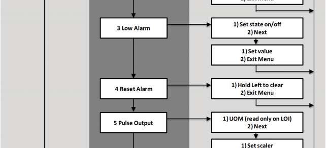
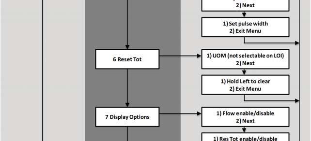
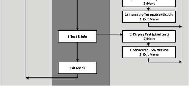
67 Installation and Operation Manual Section 3 Operation LeftLOIbutton=Scrollthroughoptions. RightLOIbutton=Activateoption. Figure 3-4 Model MT3809 Electronics LOI Chart Menu 3-7
MT3809G Series. Metal Tube Variable Area Flowmeters. Overview. Product Description. Variable Area
 DS-VA-MT3809G-eng December, 2017 Data Sheet MT3809G Series MT3809G General Purpose Housing Variable Area Metal Tube Variable Area Flowmeters Overview Brooks MT3809 meter operation is based on the variable
MT3809G Series. Metal Tube Variable Area Flowmeters. Overview. Product Description. Variable Area
 DS-VA-MT3809G-eng April, 2016 Data Sheet MT3809G Series MT3809G General Purpose Housing Variable Area Metal Tube Variable Area Flowmeters Overview Brooks MT3809 meter operation is based on the variable
MT3809G Series. Data Sheet. Metal Tube Variable Area Flowmeters. Overview. Product Description. Variable Area
 Data Sheet DS-VA-MT3809G-eng July, 2015 MT3809G Series MT3809G General Purpose Housing Variable Area Metal Tube Variable Area Flowmeters Overview Brooks MT3809 meter operation is based on the variable
MT3809G Series. Data Sheet. Metal Tube Variable Area Flowmeters. Overview. Product Description. Variable Area
 Data Sheet MT3809G Series MT3809G General Purpose Housing Variable Area Metal Tube Variable Area Flowmeters Overview Brooks MT3809 meter operation is based on the variable area principle. The all metal
Ar-Mite TM Low Flow Armored Flowmeter
 Data Sheet Brooks Ar-Mite TM MT 3750C Ar-Mite TM Low Flow Armored Flowmeter Ar-Mite TM Model MT 3750 Metal Tube Flowmeter Ar-Mite TM Model MT 3750 Metal Tube Flowmeter with Transmitter or Inductive Alarm
MT3750C Series. Metal Tube Variable Area Flowmeters. Ships in 5 days. Overview. Product Description. Features. Variable Area
 DS-VA-MT3750C-eng September, 2017 Data Sheet MT3750C Series MT3750C Series Ships in 5 days Overview Variable Area Metal Tube Variable Area Flowmeters Brooks MT3750 meter operation is based on the variable
Metal Tube Variable Area Flowmeter with Optional Electronics based on Smart Meter Manager Technology
 Data Sheet Brooks Model MT 3810 Metal Tube Variable Area Flowmeter with Optional Electronics based on Smart Meter Manager Technology GENERAL FEATURES Broad range of flow capacities 5% Full scale accuracy
Brooks Models MT 3809 and 3819 Metal Tube Variable Area Flowmeters with Optional Electronics based on Smart Meter Manager TM Technology
 Data Sheet Models MT 3809 & 3819 Brooks Models MT 3809 and 3819 Metal Tube Variable Area Flowmeters with Optional Electronics based on Smart Meter Manager TM Technology Broad range of flow capacities 2%
MT3750C Series. Metal Tube Variable Area Flowmeters. Overview. Product Description. Features. Variable Area
 DS-VA-MT3750C-eng March, 2015 Data Sheet MT3750C Series MT3750C Series Variable Area Metal Tube Variable Area Flowmeters Overview Brooks MT3750 meter operation is based on the variable area principle.
User s Manual YTA610 and YTA710 NEPSI Certification
 User s Manual YTA60 and YTA70 NEPSI Certification [Option code: /NS, /NS5 and /NF] st Edition . INTRODUCTION Thank you for purchasing the YTA60 and YTA70 Temperature transmitters. This manual contains
Brooks Model MT 3810 Metal Tube Variable Area Flowmeter with Optional Electronics Based on Smart Meter Manager TM Technology
 December, 2008 Model MT 3810 Brooks Model MT 3810 Metal Tube Variable Area Flowmeter with Optional Electronics Based on Smart Meter Manager TM Technology Brooks Model MT 3810 Model MT 3810 December, 2008
Brooks MT3750 Low Flow Armored Flowmeter
 Brooks MT3750 Low Flow Armored Flowmeter ArMite TM Model MT3750 Metal Tube Flowmeter ArMite TM Model MT3750 Metal Tube Flowmeter with Transmitter or Inductive Alarm Benefits: Wetted Parts made from Stainless
Artisan Technology Group is your source for quality new and certified-used/pre-owned equipment
 Artisan Technology Group is your source for quality new and certified-used/pre-owned equipment FAST SHIPPING AND DELIVERY TENS OF THOUSANDS OF IN-STOCK ITEMS EQUIPMENT DEMOS HUNDREDS OF MANUFACTURERS SUPPORTED
Intrinsically Safe, NEMA 4, Type 4X, IP67 Loop-Powered Meter
 PD685 Intrinsically Safe, NEMA 4, Type 4X, IP67 Loop-Powered Meter Actual Size Digits C US Intrinsically Safe 3½ Digits LARGE DISPLAY NEMA 4, Type 4X, IP67 Loop-Powered Field-Mount Process Meter 4-20 ma
OPTIBAR DP 7060 Supplementary Instructions
 OPTIBAR DP 7060 Supplementary Instructions Differential pressure transmitter Category ATEX II 1/2G, 2G Ex db ia IIC T6...T1 Ga/Gb, Gb IECEx Ex db ia IIC T6...T1 Ga/Gb, Gb Housing Aluminium: Single chamber,
Additional Operating Instructions SITRANS F. Vortex flowmeters. SITRANS FX330 Ex-d.
 Additional Operating Instructions SITRANS F Vortex flowmeters Ex-d Edition 09/208 CONTENTS Safety instructions 3. General notes... 3.2 EU conformity... 3.3 Approval according to the IECEx scheme... 3.4
Brooks MT3600 Series Metal Tube Variable Area Flowmeters
 Data Sheet Flanged, NPT or socket-welded connections 10% full scale accuracy Disassembly for cleaning without removal from the process line Standard direct reading, detachable scales Permanent magnetic
Dräger Polytron 8200 CAT Detection of flammable gases and vapors
 Dräger Polytron 8200 CAT Detection of flammable gases and vapors The Dräger Polytron 8200 CAT is an advanced explosion proof transmitter for the detection of flammable gases in the lower explosion limit
Dräger Polytron 8310 IR Detection of flammable gases and vapour
 Dräger Polytron 8310 IR Detection of flammable gases and vapour The Dräger Polytron 8310 IR is an advanced explosion proof transmitter for the detection of combustible gases in the lower explosion limit
Annubar Flowmeter Series
 Reference Manual Appendix B Approvals Annubar Flowmeter Series Hazardous Locations Installations.................. page B-1 Rosemount 3051SFA Product Certifications.......... page B-1 Rosemount 3095MFA
Dräger Polytron 5200 CAT Detection of flammable gases and vapours
 Dräger Polytron 5200 CAT Detection of flammable gases and vapours The Dräger Polytron 5200 CAT is a cost-effective explosion-proof transmitter for the detection of flammable gases in the lower explosion
Additional Operating Instructions SITRANS F. Vortex flowmeters. SITRANS FX330 Ex-nA.
 Additional Operating Instructions SITRANS F Vortex flowmeters Ex-nA Edition 08/207 CONTENTS Safety instructions 3. General notes... 3.2 EU conformity... 3.3 Approval according to the IECEx scheme... 3.4
Rosemount 3100 Series Ultrasonic Level Transmitters
 Product Data Sheet Ultrasonic Level Transmitters Non-contacting measurement with no moving parts Integral LCD and push-buttons as standard for on-site programming Continuous measurement of level or distance-to-surface.
Dräger Polytron 8000 Stationary gas detector (EC)
") Dräger Polytron 8000 Stationary gas detector (EC) The microprocessor-based transmitter can be equipped with various electrochemical DrägerSensors. This way, you can easily detect oxygen and various toxic
Dräger Polytron 8000 Stationary gas detector (EC) The microprocessor-based transmitter can be equipped with various electrochemical DrägerSensors. This way, you can easily detect oxygen and various toxic
Rosemount 3100 Series Ultrasonic Level Transmitters
 Product Data Sheet Ultrasonic Level Transmitters Non-contacting measurement with no moving parts Integral LCD and push-buttons as standard for on-site programming Continuous measurement of level or distance-to-surface.
Rosemount 8800D Series Vortex Flowmeter. Quick Start Guide , Rev FE October 2018
 Rosemount 8800D Series Vortex Flowmeter 00825-0100-4004, Rev FE 1 About this guide This guide provides basic guidelines for the Rosemount 8800D Series Vortex Flowmeter. It does not provide instructions
Dräger Polytron 5100 EC Detection of toxic gases and vapors
 Dräger Polytron 5100 EC Detection of toxic gases and vapors The Dräger Polytron 5100 EC is a cost-effective explosion proof transmitter for the detection of toxic gases or oxygen. It uses a high performance
Dräger Polytron 8700 IR Detection of flammable gases and vapors
 Dräger Polytron 8700 IR Detection of flammable gases and vapors The Dräger Polytron 8700 IR is an advanced explosion proof transmitter for the detection of combustible gases in the lower explosion limit
Dräger Polytron 5700 IR Detection of flammable gases and vapours
 Dräger Polytron 5700 IR Detection of flammable gases and vapours The Dräger Polytron 5700 IR is a cost effective explosion-proof transmitter for the detection of flammable gases in the lower explosive
Temperature Measurement Transmitters for field mounting
 Siemens AG 07 Overview Application The SITRANS TF can be used everywhere where temperatures need to be measured under particularly harsh conditions. For that reasons users from all industries have opted
Rosemount 8600 Series Vortex Flowmeter. Quick Start Guide , Rev EB April 2018
 Rosemount 8600 Series Vortex Flowmeter 00825-0100-4860, Rev EB April 2018 April 2018 1 About this guide This guide provides basic guidelines for the Rosemount 8600D Series Vortex Flowmeter. It does not
YTA Series Temperature Transmitters [Style: S3] EN :2006, -11:2007, -26:2007. Supply circuit: Ui=30 V, Ii=165 ma,
![YTA Series Temperature Transmitters [Style: S3] EN :2006, -11:2007, -26:2007. Supply circuit: Ui=30 V, Ii=165 ma,](/thumbs/89/98785336.jpg "YTA Series Temperature Transmitters [Style: S3] EN :2006, -11:2007, -26:2007. Supply circuit: Ui=30 V, Ii=165 ma,") User s Manual YTA Series Temperature Transmitters [Style: S3] Manual Change No. 10-008 Please use the attached sheets in the following manuals when the product is with /KU2 option and EN60000 Series based
User s Manual YTA Series Temperature Transmitters [Style: S3] Manual Change No. 10-008 Please use the attached sheets in the following manuals when the product is with /KU2 option and EN60000 Series based
Dräger Polytron Fixed Gas Detector. Dräger Polytron 5700 Infrared DrägerSensor PIR 7000 to detect combustible gases and vapors
 Dräger Polytron 5700 Fixed Gas Detector Dräger Polytron 5700 Infrared DrägerSensor PIR 7000 to detect combustible gases and vapors Dräger Polytron 5700 Including e-box for increased safety wiring The Dräger
Rosemount 3490 Series
 Product Data Sheet July 2014 00813-0100-4841, Rev DA Rosemount 3490 Series 4 20 ma + HART Compatible Controller Field mounted controller with integral multi-function LCD and keypad Tough weatherproof wall
Intrinsically Safe Pressure Transmitters for installation in hazardous locations Models IS-20-S, IS-21-S, IS-20-F, IS-21-F WIKA Datasheet IS-20
 Electronic Pressure Measurement Intrinsically Safe Pressure Transmitters for installation in hazardous locations Models IS-20-S, IS-21-S, IS-20-F, IS-21-F WIKA Datasheet IS-20 Applications Chemical, Petrochemical
Additional Operating Instructions SITRANS F. Vortex flowmeters. SITRANS FX330 Ex-i.
 Additional Operating Instructions SITRANS F Vortex flowmeters Ex-i Edition 09/2018 CONTENTS 1 Safety instructions 3 1.1 General notes... 3 1.2 EU conformity... 3 1.3 Approval according to the IECEx scheme...
Inductive slot sensor
 0102 Model Number Features 2 mm slot width Technical Data specifications Switching function Normally closed (NC) Output type NAMUR Slot width 2 mm Depth of immersion (lateral) 5... 7 mm, typ. 6 mm Output
SmartLine. RMA803 SmartLine Remote Fieldbus Indicator Specification 34-ST-03-90, December Technical Information.
 SmartLine Technical Information RMA803 SmartLine Remote Fieldbus Indicator Specification 34-ST-03-90, December 2015 Introduction The Honeywell RMA803 is a Foundation Fieldbus remote indicator suitable
Rosemount 3051CFP Integral Orifice Flowmeter
 December 2013 Rosemount 3051 Rosemount 3051CFP Integral Orifice Flowmeter See Specifications on page 47 and options for more details on each configuration. Rosemount 3051CFP Integral Orifice Flowmeters
Rosemount 752 Fieldbus Remote Indicator
 Product Data Sheet Rosemount 752 Rosemount 752 Fieldbus Remote Indicator ROSEMOUNT 752 DELIVERS: Two-wire segment powered device Displays up to 8 values Link Master Capability Optional PID, Characterizer,
Rosemount 644 Temperature Transmitter
 Quick Start Guide 00825-0200-4728, Rev GB Rosemount 644 Temperature Transmitter with 4 20 ma HART Protocol (Revision 5 and 7) Note Before installing the transmitter, confirm the correct device driver is
Rosemount 2088, 2090P, and 2090F Pressure Transmitters
 April 2013 Rosemount 2088 and 2090 Rosemount 2088, 2090P, and 2090F Pressure Transmitters with 4-20 ma HART and 1-5 Vdc HART Low Power Protocol Start Step 1: Mount the Transmitter Step 2: Set the Jumpers
Rosemount 752 FOUNDATION Fieldbus Remote Indicator
 Rosemount 752 FOUNDATION Fieldbus Remote Indicator Product Data Sheet 00813-0100-4377, Rev FA Two-wire segment powered device Displays up to eight values Link Master Capability Optional PID, Characterizer,
Dräger Polytron 8100 EC Detection of toxic gases and oxygen
 Dräger Polytron 8100 EC Detection of toxic gases and oxygen The Polytron 8100 EC is Dräger s top of the line explosion-proof transmitter for the detection of toxic gases or oxygen It uses a high performance
Model 144H. Product Data Sheet , Rev DB February Content
 Rosemount 144 PC-Programmable Temperature Transmitter Provides an installation-ready solution for temperature monitoring applications using Complete Point Solutions (CPS) Increases measurement accuracy
Dräger Polytron 8700 IR Detection of flammable gases and vapors
 Dräger Polytron 8700 IR Detection of flammable gases and vapors The Dräger Polytron 8700 IR is an advanced explosion proof transmitter for the detection of combustible gases in the lower explosion limit
Rotameter series 250 metal tube variable area flowmeter
 Technical data Sheet Flow meter Rotameter series 250 metal tube variable area flowmeter MODELES 250 Stainless Steel indicator 250 PTFE 250 indicator + Alarm 250 electronic transmitter 4-20mA 250 electronic
Dräger Polytron 8100 EC Detection of toxic gases and vapors
 Dräger Polytron 8100 EC Detection of toxic gases and vapors The Polytron 8100 EC is Dräger s top of the line explosion proof transmitter for the detection of toxic gases or oxygen It uses a high performance
VERSAFLOW VORTEX Supplementary instructions
 VERSAFLOW VORTEX Supplementary instructions Vortex flowmeter Equipment category II 2G CONTENTS VERSAFLOW VORTEX 1 Safety instructions 3 1.1 General notes... 3 1.2 EC conformity... 3 1.3 Approval according
Rosemount 148 Temperature Transmitter. Quick Start Guide , Rev GA September 2016
 Rosemount 148 Temperature Transmitter 00825-0100-4148, Rev GA NOTICE This guide provides basic guidelines for the Rosemount 148. It does not provide instructions for detailed configuration, diagnostics,
OPTIWAVE X500 Supplementary Instructions
 OPTIWAVE X500 Supplementary Instructions OPTIWAVE 3500 C OPTIWAVE 6500 C OPTIWAVE 7500 C Supplementary Instructions for ATEX applications KROHNE CONTENTS OPTIWAVE X500 1 General safety information 4 1.1
Dräger Polytron 8720 IR Detection of carbon dioxide
 Dräger Polytron 8720 IR Detection of carbon dioxide The Dräger Polytron 8720 IR is an advanced explosion proof transmitter for the detection of carbon dioxide in percent volume or ppm It uses a high performance
Dräger Polytron 5200 CAT Detection of flammable gases and vapours
 Dräger Polytron 5200 CAT Detection of flammable gases and vapours The Dräger Polytron 5200 CAT is a cost-effective explosion-proof transmitter for the detection of flammable gases in the lower explosion
Rosemount 248 Temperature Transmitter
 Product Data Sheet November 2013 00813-0100-4825, Rev KA Rosemount 248 Temperature Transmitter Basic temperature transmitter offers a reliable solution for temperature monitoring points transmitter design
Dräger Polytron 5100 EC Detection of toxic gases and vapors
 Dräger Polytron 5100 EC Detection of toxic gases and vapors The Dräger Polytron 5100 EC is a cost-effective explosion proof transmitter for the detection of toxic gases or oxygen It uses a high performance
Rosemount 4500 Hygienic Pressure Transmitter. Start
 Quick Installation Guide June 2007 Rosemount 4500 Rosemount 4500 Hygienic Pressure Transmitter ProductDiscontinued Start Step 1: Mount the Transmitter Step 2: Set the Switches Step 3: Connect Wiring and
Rosemount 2051 Pressure Transmitter with 4-20 ma HART and 1-5 Vdc HART Low Power Protocol
 Quick Installation Guide August 2009 Rosemount 2051 Rosemount 2051 Pressure Transmitter with 4-20 ma HART and 1-5 Vdc HART Low Power Protocol Start Step 1: Mount the Transmitter Step 2: Consider Housing
Temperature measurement with SITRANS T siemens.com/processinstrumentation
 Top values in precision and reliability Temperature measurement with SITRANS T siemens.com/processinstrumentation Temperatures firmly under control Top process quality and efficiency are key factors for
Rosemount 8800D Series Vortex Flowmeter
 Quick Installation Guide Rosemount 8800D Rosemount 8800D Series Vortex Flowmeter Start Step 1: Mount the Flowmeter Step 2: Consider Housing Rotation Step 3: Set Jumpers and Switches Step 4: Connect Wiring
Rosemount 3051 Pressure Transmitter
 Quick Start Guide 00825-0100-4001, rev. JA Rosemount 3051 Pressure Transmitter with 4-20 ma HART and 1-5 Vdc Low Power Protocol Rosemount 3051CF Series Flowmeter Transmitter with 4-20 ma HART and 1-5 Vdc
Series 155. Mass Flow Computers TECHNICAL SPECIFICATIONS
 TECHNICAL SPECIFICATIONS Mass Flow Computers Series 155 The Kurz 155 Mass Flow Computer is a versatile system transmitter that integrates the functions of flow and temperature measurement, flow totalization,
INTRINSICALLY SAFE Pressure Transducer / Transmitter AST4400
 Pressure Transducer / Transmitter AST4400 Overview The AST4400 is a stainless steel pressure transducer with a wide variety of options. With its rugged construction and best price-toperformance ratio in
Gas cylinder scale Model GCS-1
 Electronic pressure measurement Gas cylinder scale Model GCS-1 WIKA data sheet PE 87.19 Applications Level measurement of liquid gases in gas cabinets and gas distribution systems Level measurement in
Additional Information. Introduction. Temperature transmitter for all communications protocols. Redundancy thanks to two inputs. Measurement made easy
 ABB MEASUREMENT & ANALYTICS COMMISSIONING INSTRUCTION TTF300 Field-mount temperature transmitter Temperature transmitter for all communications protocols. Redundancy thanks to two inputs. Measurement made
DSF xx10.xx xhv Ex-Atex Hall Effect Single Channel Speed Sensor
 Product ID Type # Product # Drawing # DSF 1210.00 SHV Ex-atex (2m) 374Z-05066 110428F1 DSF 1210.00 SHV Ex-atex (5m) 374Z-05176 110428F1 DSF 1210.00 SHV Ex-atex (10m) 374Z-05590 110428F1 DSF 1410.00 SHV
Model 144H. Product Data Sheet , Rev DB February Content
 Rosemount 144 PC-Programmable Temperature Transmitter Provides an installation-ready solution for temperature monitoring applications using Complete Point Solutions (CPS) Increases measurement accuracy
INTRINSICALLY SAFE Pressure Transducer / Transmitter AST4401
 Pressure Transducer / Transmitter AST4401 Overview The AST4401 is a stainless steel pressure transducer with a wide variety of options. With its rugged construction and best price-toperformance ratio in
Technical Data. General specifications Switching element function Rated operating distance s n 5 mm
 0102 Model Number Features 5 mm flush Usable up to SIL 3 acc. to IEC 61508 Application Danger! In safety-related applications the sensor must be operated with a qualified fail safe interface from Pepperl+Fuchs,
Rosemount 2051G Pressure Transmitter
 Quick Start Guide 00825-0700-4101, Rev AB Rosemount 2051G Pressure Transmitter with 4 20 ma HART Protocol (Revision 5 and 7) Quick Start Guide NOTICE This guide provides basic guidelines for Rosemount
Operating Instructions Edition 02/2007
 Operating Instructions Edition 02/2007 Temperature Transmitter 7NG3214 with PROFIBUS PA 7NG3215 with FOUNDATION Fieldbus sitrans Introduction 1 General safety notes 2 SITRANS T Temperature transmitter
Rosemount 2090F Hygienic Pressure Transmitter
 Rosemount 2090F Hygienic Pressure Transmitter Product Data Sheet November 2016 00813-0100-4698, Rev FC Conforms to 3-A Sanitary Standards Features CIP/SIP service for process temperatures up to 284 F (140
Rosemount 3051CFC Compact Flowmeter
 CFC Compact Flowmeter CFC Compact Flowmeters provide a quick, reliable installation between existing raised face flanges. Depending on your application needs, you can reduce energy loss with the Compact
Technical Data. General specifications. Rated operating distance s n 5 mm
 0102 Model Number Features 5 mm non-flush Usable up to SIL 2 acc. to IEC 61508 Technical Data specifications Switching function Normally closed (NC) Output type NAMUR Rated operating distance s n 5 mm
Rosemount 2090F Hygienic Pressure Transmitter
 Rosemount 2090F Hygienic Pressure Transmitter Product Data Sheet December 2017 00813-0100-4698, Rev GA Conforms to 3-A Sanitary Standards Features CIP/SIP service for process temperatures up to 284 F (140
Pressure sensors. Ex ia I / IIC T6 acc. to ATEX. Features. Description. Measuring ranges. Applications
 Force Pressure Temperature Switch Pressure sensors Ex ia I / IIC T6 acc. to ATEX with internal diaphragm with front flush diaphragm Accuracy: 0,25% and 0,5 % Standard output: 4...20 ma; 2-wire system Description
PROCESS AUTOMATION PRECISE VALUES LEVEL MEASUREMENT TECHNOLOGY
 PROCESS AUTOMATION PRECISE VALUES LEVEL MEASUREMENT TECHNOLOGY POINT LEVEL DETECTION In applications like overfill protection, min/max control, or overflow and dry-run protection, the limit value switches
Dräger Polytron 8310 Stationary gas detector (DSIR)
") Stationary gas detector (DSIR) SIMPLE INSTRUMENT MANAGEMENT POISON-RESISTANT AND FAIL-SAFE THANKS TO DIGITAL COMMUNICATION The DrägerSensor IR offers several benefits: technological advantages such as
Stationary gas detector (DSIR) SIMPLE INSTRUMENT MANAGEMENT POISON-RESISTANT AND FAIL-SAFE THANKS TO DIGITAL COMMUNICATION The DrägerSensor IR offers several benefits: technological advantages such as
Level Measurement Continuous level measurement - Ultrasonic transmitters
 Overview Configuration Parabolic mounting is a 2-wire loop powered ultrasonic transmitter for level, volume and flow monitoring of liquids in open channels, storage vessels, and simple process vessels.
AM54. Armored Variable Area Flowmeter Series AM54331/32 Series AM54371/72/73/74 Series AM54431/32 Series AM54471/72/73/74
 AM54 Instruction Bulletin North American Installation Addendum Document Number PN25016 Armored Variable Area Flowmeter Series AM54331/32 Series AM54371/72/73/74 Series AM54431/32 Series AM54471/72/73/74
Rosemount Pipe Clamp Sensor. Reference Manual , Rev BA February 2014
 Rosemount Pipe Clamp Sensor Reference Manual Reference Manual Title Page The Rosemount 0085 Pipe Clamp Sensor NOTICE Read this manual before working with the product. For personal and system safety, and
Rosemount 3051S MultiVariable Transmitter Rosemount 3051SF Series Flowmeter MultiVariable Transmitter
 Quick Start Guide 00825-0100-4803, Rev EF Rosemount 3051S MultiVariable Transmitter Rosemount 3051SF Series Flowmeter MultiVariable Transmitter Quick Start Guide NOTICE This guide provides basic guidelines
Rosemount 4500 Hygienic Pressure Transmitter
 Product Data Sheet Rosemount 4500 Rosemount 4500 Hygienic Pressure Transmitter Hygienic design conforms to 3-A and EHEDG standards Demonstrated best-in-class performance during SIP/CIP for process temperatures
REGULATIONS EUROPEAN ATEX DIRECTIVE. INTERNATIONAL SCHEME: IECEx AREAS CLASSIFICATION DEFINED BY DIRECTIVE 1999/92/EC
 EUROPEAN ATEX DIRECTIVE > European Directive 2014/34/EU ATEX Directive 2014/34/EU is a "new approach" directive that applies to protective systems against explosions as well as all equipment used in or
Certificate of Compliance
 FF0002 Certificate of Compliance Certificate: 2792948 Issued to: Siemens Canada Limited 1954 Technology Drive Peterborough, ON K9J 7B1 Canada Attention: Mr. Lee Rogers The products listed below are eligible
Rosemount 214C Sensor. Quick Start Guide , Rev AF August 2017
 Rosemount 214C Sensor 00825-0400-2654, Rev AF NOTICE This guide provides basic guidelines for Rosemount 214C Sensor models. If the sensor was ordered assembled to a temperature thermowell or transmitter,
Radar Transmitters SITRANS LR400 (HART/PROFIBUS PA) Quick Start Manual 03/2013 SITRANS
 Quick Start Manual 03/2013 SITRANS") Radar Transmitters SITRANS LR400 (HART/PROFIBUS PA) Quick Start Manual 03/2013 SITRANS SITRANS LR 400 Quick Start Manual This manual outlines the essential features and functions of the SITRANS LR 400
Radar Transmitters SITRANS LR400 (HART/PROFIBUS PA) Quick Start Manual 03/2013 SITRANS SITRANS LR 400 Quick Start Manual This manual outlines the essential features and functions of the SITRANS LR 400
Rosemount 248 Temperature Transmitter. Quick Start Guide , Rev. EA April 2013
 Rosemount 248 Temperature Transmitter 00825-0100-4825, Rev. EA NOTICE This installation guide provides basic guidelines for the Rosemount 248 Wireless. It does not provide instructions for detailed configuration,
Rosemount 2051T In-Line Pressure Transmitter
 Rosemount 2051T In-Line Pressure Transmitter 2051T In-Line Wireless Pressure Transmitter Configuration Transmitter Output Code 4-20 ma HART 2051 A 2051 with Selectable HART (1) Lower Power 2051 2051 with
Mobrey MSP900SH Level and MSP900FH Flow Ultrasonic Transmitters
 Product Data Sheet Non-contacting measurement with no moving parts Fast and simple to install and configure Continuous measurement of level, contents (volume), or open channel flow MCERTS certified version
Dräger Polytron 7000 Fixed gas detector
 DETECTION PERSONAL PROTECTION DIVING TECHNOLOGY SYSTEM TECHNOLOGY SERVICES Dräger Polytron 7000 Fixed gas detector ST-3751-2003 The Dräger Polytron 7000 is a gas detector that can satisfy all toxic and
Model D12-IR. Digital Gas Transmitter...
 Model D12-IR Digital Gas Transmitter... ATI s Series D12 gas transmitter line now includes a versatile Infrared system that can be configured for LEL or select toxic gases. The D12-IR utilizes a compact
Specifications - Installation and Operating Instructions 2X 1/2 NPT OR M20 ELECTRICAL ENTRY. 3/4 NPT or 3/4 BSPT 5/8 [15.88]
![Specifications - Installation and Operating Instructions 2X 1/2 NPT OR M20 ELECTRICAL ENTRY. 3/4 NPT or 3/4 BSPT 5/8 [15.88]](/thumbs/82/84779364.jpg "Specifications - Installation and Operating Instructions 2X 1/2 NPT OR M20 ELECTRICAL ENTRY. 3/4 NPT or 3/4 BSPT 5/8 [15.88]") Series PMT2 Particulate Transmitter Specifications - Installation and Operating Instructions Bulletin PC-PMT2 2X 1/2 NPT OR M20 ELECTRICAL ENTRY THREADED MOUNT Probe A Length in [mm] 3 3 [76.20] 5 5 [127.00]
Series PMT2 Particulate Transmitter Specifications - Installation and Operating Instructions Bulletin PC-PMT2 2X 1/2 NPT OR M20 ELECTRICAL ENTRY THREADED MOUNT Probe A Length in [mm] 3 3 [76.20] 5 5 [127.00]
Immersion heaters for ATEX/IECEx hazardous areas or in non-atex version
 for ATEX/IECEx hazardous areas or in non-atex version * Non contractual picture Warning It is imperative to read these instructions carefully before installing or maintaining the equipment. MI100EN 09/2017
A Characteristics for Electrical Equipment integrated Into SLR Enclosure - Intrinsically Safe Reference Document
 A190325 Characteristics for Electrical Equipment integrated Into SLR Enclosure - Intrinsically Safe Reference Document CONTENTS INTRODUCTION 1. DUAL CERTIFIED COMPONENTS 1.1 Simple Apparatus Switches For
Software Version 2.01 LEVEL MONITOR MODEL 220
 Software Version 2.01 LEVEL MONITOR MODEL 220 19 April 2000 CONTENTS 1. Introduction 1 1.1 Model Number Designation 2 1.2 Intrinsic Safety Considerations 3 2. Specification 4 3. Operation 6 3.1 Display
Continuous level measurement Ultrasonic transmitters
 Overview Configuration Parabolic mounting is a 2-wire loop powered ultrasonic transmitter for level, volume and flow monitoring of liquids in open channels, storage vessels, and simple process vessels.
INSTRUCTION MANUAL. SIL 3 - SIL 2 IIB Group Power Supply for Hazardous Area Equipment DIN-Rail Model PSD1001C PSD1001C
 PSD1001C INSTRUCTION MANUAL SIL 3 SIL 2 IIB Group Power Supply for Hazardous Area Equipment DINRail Model PSD1001C PSD1001C SIL 3 SIL 2 IIB Group Power Supply for hazardous Area Equipment ISM006510 General
Rosemount 4600 Oil & Gas Panel Pressure Transmitter
 Product Data Sheet October 2017 00813-0100-4022, Rev LA Rosemount 4600 Oil & Gas Panel Pressure Transmitter A compact, lightweight, all-welded stainless steel design Up to 40:1 rangeability for increased
Rosemount 4600 Oil & Gas Panel Pressure Transmitter. Quick Start Guide , Rev GA September 2017
 Rosemount 4600 Oil & Gas Panel Pressure Transmitter 00825-0100-4022, Rev GA NOTICE NOTICE This guide provides basic guidelines for the Rosemount 4600 Oil & Gas Panel Pressure Transmitter. It does not provide
Danfoss gas detection unit Type GD Heavy Duty
 Data sheet Danfoss gas detection unit Type GD Heavy Duty The Heavy Duty gas detection units are used for monitoring and warning of hazardous Ammonia gas concentrations. They are intended for ATEX/ IECEx