WFDE Series Waterflow Detector
|
|
|
- Alberta Grant
- 6 years ago
- Views:
Transcription

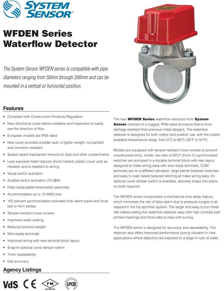
1 WFDE Series Waterflow Detector The System Sensor WFDE series is compatible with pipe diameters ranging from 50mm through 200mm and can be mounted in a vertical or horizontal position. Features Compliant with Construction Products Directive EC Certificate Number 0786 CPD WFD30-2E models install in 50.8mm (2 ) hole sizes IP54-rated enclosure Sealed retard mechanism assures that the retard is not contaminated by dust and dirt when the cover is removed Visual switch activation permits installer to accurately set the retard, even under extremely noisy conditions Rugged, dual SPDT switches are enclosed in a durable terminal block for added strength 100% synchronization activates both alarm panel and local bell simultaneously Robust Construction. The WFDE series consists of a rugged, IP54-rated enclosure. Designed for both indoor and outdoor use, the WFDE series operates across a wide temperature range, from 0 C to 68 C (32 F to 155 F). Reliable Performance. WFDE models are equipped with tamperresistant cover screws to prevent unauthorized entry. Inside, two sets of SPDT (Form C) synchronized switches are enclosed in a durable terminal block to ensure reliable performance. False Alarm Immunity. The WFDE series incorporates a mechanical retard feature, which minimizes the risk of false alarm due to pressure surges or air trapped in the sprinkler system. In addition, the mechanical retard s unique sealed design is immune to dust and other contaminants. Simplified Operation. The WFDE series is designed to simplify installation. Two conduit openings permit easy attachment to the local alarm system. The retard mechanism and dual SPDT switches are field-replaceable. Agency Listings TE83724 VdS G Z0A7.AH Scientific Services Laboratory afp
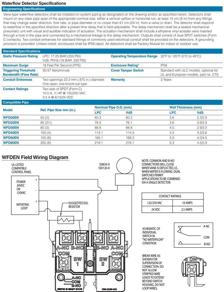
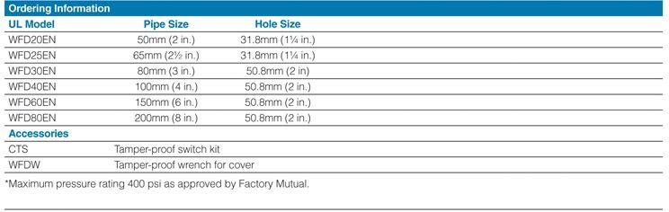
2 Waterflow Detector Specifications Engineering Specifications Vane-type System Sensor WFDE series waterflow detectors shall be installed on system piping as designated on the drawings and/or as specified herein. Detectors shall mount on any clear pipe span of the appropriate nominal size, either a vertical upflow or horizontal run, at least 15 cm (6 in.) from any fittings, which may change water direction, flow rate or pipe diameter, or no closer than 61 cm (24 in.) from a valve or drain. The detector shall respond to waterflow in the specified direction after a preset time delay, which is field adjustable. The delay mechanism shall be a sealed mechanical pneumatic unit with visual indication of actuation. The actuation mechanism shall include a polyethylene vane inserted through a hole in the pipe and connected by a mechanical linkage to the delay mechanism. Outputs shall consist of dual SPDT switches (Form C contacts). Two conduit entrances (one of which is a knockout type) for standard fittings of commonly used electrical conduit shall be provided on the detectors. A grounding provision is provided. WFDE waterflow detectors shall be approved by Factory Mutual, LPC, VdS and SSL. Standard Specifications Static Pressure Rating Triggering Threshold Bandwidth (Flow Rate) Contact Ratings; Two sets of SPDT (Form C) Conduit Entrances Operating Temperature Range Enclosure Rating U.S. Patent Numbers 5,213,205 Warranty 3 Years LPC: BAR (250 PSI) VdS: PN16 (16 BAR, 232 PSI) liters/minute /250 VAC VDC Two openings 22.2mm (.875 in.) diameter. One open, one knock-out type 0 C to 68 C (32 F to 155 F) IP54 Compatible Pipe Ref. Pipe Nominal Pipe O.D. Wall Thickness Model Size mm (mm) (mm) (in.) LPC VdS LPC VdS WFD20E 50 (2) /2.9 WFD25E 65 (2½) /2.9 WFD30-2E 80 (3) /3.2 WFD40E 100 (4) /3.6 WFD60E 150 (6) /4.5 WFD80E 200 (8) /5.9 Shipping Weight WFD20E Model WFD25E 1.85 kg (4.08 lbs.) Delay Adjustment Dial WFD30-2E WFD40E WFD60E WFD80E 2.05 kg (4.53 lbs.) 2.36 kg (5.20 lbs.) 3.03 kg (6.68 lbs.) 3.45 kg (7.70 lbs.) WFDE Field Wiring Diagram UL-LISTED PATIBLE CONTROL PANEL POWER + 24VDC OR 120VDC INITIATING LOOP + SUGGESTED EOL RESISTOR SSM24-X SSV120-X NOTE: MON AND B-NO CONNECTIONS WILL CLOSE WHEN VANE IS DEFLECTED, I.E., WHEN WATER IS FLOWING. DUAL SWITCHES PERMIT APPLICATIONS TO BE BINED ON A SINGLE DETECTOR. CONTACT RATINGS 125/250 VAC 10 AMPS 24 VDC 2.5 AMPS SCHEMATIC OF INDIVIDUAL SWITCH IN NO WATERFLOW CONDITION BREAK WIRE AS SHOWN FOR SUPERVISION OF CONNECTION. DO NOT ALLOW STRIPPED WIRE LEADS TO EXTEND BEYOND SWITCH HOUSING. DO NOT LOOP WIRES. A-NC B-NO Delay adjustment dial Dial setting Dial setting equals delay in seconds. Reference only. Ordering Information Model Pipe Size Hole Size WFD20E 50mm (2 ) 31.8mm (1¼ ) WFD25E 65mm (2½ ) 31.8mm (1¼ ) WFD30-2E 80mm (3 ) 50.8mm (2 ) WFD40E 100mm (4 ) 50.8mm (2 ) WFD60E 150mm (6 ) 50.8mm (2 ) WFD80E 200mm (8 ) 50.8mm (2 )

3
4
5
6
7
8

9 OSY2 Supervisory Switch The System Sensor OSY2 is used to monitor the open position of an Outside Screw and Yoke (OS&Y) type gate valve. Features NEMA 3R-rated enclosure User-friendly mounting bracket fits newer valve yokes Single side conduit entry does not require right angle fittings Adjustable length actuator eliminates the need for cutting the shaft Accommodates up to 12 AWG wire Three position switch monitors vandal and valve close signals Two SPDT contacts are enclosed in a durable terminal block for added strength 100 percent synchronization activates both alarm panel and local bell simultaneously Robust Construction. The OSY2 consists of a rugged housing, intended for indoor and outdoor use. When installed with the actuator in the vertical position, the OSY2 is NEMA 3R rated per UL. Application Flexibility. The OSY2 features a user-friendly mounting bracket and adjustable shaft to permit mounting to most OS&Y valves, ranging in size from 1 to 12. Its right angle design and wide bracket span provides maximum clearance for valve components, to accommodate troublesome valves. Removing the OSY2 s gate valve bracket allows the unit to monitor side-bracketstyle pressure reducing valves. Simplified Operation. Installation is made easier with the OSY2 s single side conduit entrance. By providing a direct conduit pathway to the electrical source, right angle fittings are not required. Installation is further simplified by the OSY2 s adjustable length actuator, which eliminates the need for cutting the shaft. Reliable Performance. The OSY2 is equipped with tamperresistant cover screws to prevent unauthorized entry. Inside, two sets of SPDT (Form C) synchronized switches are enclosed in a durable terminal block to assure reliable performance. Agency Listings S739 CS169 OW6A8.AY E :118
10 OSY2 Specifications Architectural/Engineering Specifications Model shall be model number OSY2 supervisory switch as manufactured by System Sensor. OSY2 shall be installed on each valve as designated on the drawings and/or as specified herein. Switches shall be mounted so as not to interfere with the normal operation of the valve and shall be adjusted to operate within two revolutions of the valve control or when the stem has moved no more than one-fifth of the distance from its normal position. The mechanism shall be contained in a weatherproof die cast metal housing that provides a side entrance for ½ conduit and incorporates the necessary facilities for attachment to the valve. A grounding provision is provided. The switch assembly shall include two switches each with a rated capacity of /250VAC and VDC. The cover shall contain tamper-resistant screws for which a security wrench will be provided with each switch. The OSY2 shall be Underwriters Laboratories listed for indoor or outdoor use. The OSY2 shall be Factory Mutual, CSFM, and MEA approved. Physical Specifications Operating Specifications Overall Switch Dimensions 5¾ H x 3½ W x 3¼ D (14.6cm x 8.9cm x 8.2cm) Contact Ratings Two sets of SPDT (Form C) /250VAC; 6/12/24VDC Shipping Weight 2.8 lbs. (1.3 kg) Enclosure Rating UL indoor/outdoor NEMA 3R when mounted with the actuator vertical Operating Temperature Range 32 F to 120 F ( 0 C to 49 C) NOTE: The OSY2 will operate from 40 F to 120 F ( 40 C to 49 C); however UL does not test control valve supervisory switches below 32 F (0 C). Cover Tamper Switch Standard with ULC model Optional for UL model, part no Maximum Stem Extension 25/8 (6.7cm) Service Use Automatic Sprinkler: NFPA 13 One or Two Family Dwelling: NFPA 13D Residential Occupancies up to 4 stories: NFPA 13R National Fire Alarm code: NFPA 72 Bracket Span ¼ H x 6¾ W x 1 D (5.7cm x 17.1cm x 2.5cm) Warranty 3 years Conduit Entrances One single side open for ½ conduit U.S. Patent Nos. 5,478,038; 5,213,205 Electrical Connections for OSY2 TOP VIEW SWITCH 1 CONTACT RATINGS 125/250 VAC 10 AMPS 24 VDC 2.5 AMPS NOTE: MON AND B CONNECTIONS WILL CLOSE WHEN VALVE MOVES 1 /5 OF ITS TOTAL TRAVEL DISTANCE. OSY2 Mounting The following are examples of acceptable mounting positions: A B B A STRIP GAUGE SWITCH 2 TYPICAL FACP CONNECTION SUP. SWITCH SUP. SWITCH TO NONSILENCEABLE INITIATING ZONE OF LISTED FACP B B B B END-OF-LINE RESISTOR Actuator Vertical (Down) Actuator Horizontal The following mounting position is not acceptable: TYPICAL LOCAL BELL CONNECTION TO POWER SOURCE PATIBLE WITH BELL B LOCAL BELL BREAK WIRE AS SHOWN FOR SUPERVISION OF CONNECTION. DO NOT ALLOW STRIPPED WIRE LEADS TO EXTEND BEYOND SWITCH HOUSING. DO NOT LOOP WIRES. Actuator Vertical (Pointing Up) Ordering Information Part No. Description OSY2 Outside Screw and Yoke valve supervisory switch OSY2A Outside Screw and Yoke valve supervisory switch (ULC model) Accessories OSYRK Replacement hardware kit (wrenches, screw pack and J hooks) WFDW Replacement tamper-proof wrench for cover Cover tamper switch kit HEXW Replacement hex wrench S07-66-XX Tamper screws for cover

11 PIBV2 Supervisory Switch System Sensor s PIBV2 supervisory switch monitors the open position of post indicator and butterfly control valves. Features NEMA 3R rated enclosure Bi-directional actuator Easy single side conduit entry Adjustable length actuator with breakaway feature Built to accommodate up to 12 AWG wire Two sets of SPDT contacts enclosed in a durable terminal block 100 percent synchronization activates alarm panel and local bell simultaneously Operating temperature range 40 F to 120 F ( 40 C to 49 C) Tamper resistant cover screws Robust Construction: The PIBV2 s rugged housing is intended for indoor and outdoor use. When installed with the actuator in the vertical position, the PIBV2 is NEMA 3R rated per UL. Application Flexibility: The PIBV2 features a flexible design, which accommodates post indicator, butterfly, and many other types of wall post, recessed wall post and pressure reducing valves. The PIBV2 s unique bi-directional actuator allows the unit to be installed in either rising or falling flag installations. Simplified Installation: Installation is made easier with the PIBV2 s single side conduit entrance. By providing a direct conduit pathway to the electrical source, right angle fittings are not required. Installation is further simplified by the PIBV2 s adjustable length actuator with a convenient breakaway feature for installation on shorter valves. This eliminates the need for cutting the shaft. Reliable Performance: The PIBV2 has 100 percent synchronization which activates the alarm panel and local bell simultaneously. In addition, the switch is designed to operate in temperatures ranging from 40 F to 120 F ( 40 C to 49 C). The PIBV2 is equipped with tamper resistant cover screws to prevent unauthorized entry. Inside, two sets of SPDT (Form C) synchronized switches are enclosed in a durable terminal block to assure reliable performance. Agency Listings S739 CS :118 OW6A8.AY E
12 PIBV2 Specifications Architectural/Engineering Specifications Model shall be model number PIBV2 Post Indicator Butterfly Valve supervisory switch as manufactured by System Sensor. PIBV2 shall be installed on each valve as designated on the drawings and/or as specified herein. Switches shall be mounted so as not to interfere with the normal operation of the valve and shall be adjusted to operate within two revolutions of the valve control or when the valve flag has moved no more than one-fifth of the distance from its normal position. The mechanism shall be contained in a weatherproof die cast metal housing, which shall provide a side entrance for ½ conduit and incorporate a ½ NPT nipple for attachment to the valve body. A grounding provision is provided. The switch assembly shall include two switches each with a rated capacity of /250V AC and V DC. The cover shall contain tamper-resistant screws for which a security wrench will be provided with each switch. PIBV2 shall be Underwriters Laboratories listed for indoor or outdoor use. The PIBV2 shall be Factory Mutual, CSFM, and MEA approved. Physical Specifications Operating Specifications Overall Switch Dimensions 4¼ H 3½ W 3¼ D (10.8cm 8.9cm 8.2cm) Contact Ratings Two sets of SPDT (Form C) /250V AC; 6/12/24V DC Shipping Weight 2 lbs. (0.9 kg) Enclosure Rating UL indoor/outdoor NEMA 3R when mounted with the actuator vertical Operating Temperature Range 40 F to 120 F ( 40 C to 49 C) Cover Tamper Switch Standard with ULC model Optional for UL model, part no Maximum Stem Extension 35/32 (8.0 cm) Service Use Automatic Sprinkler: NFPA 13 One or Two Family Dwelling: NFPA 13D Residential Occupancies up to 4 stories: NFPA 13R National Fire Alarm code: NFPA 72 Mounting ½ NPT nipple Warranty 3 years Conduit Entrances One single side open for ½ conduit U.S. Patent No. 5,213,205 Electrical Connections for PIBV2 Switch 1 Top View PIBV2 Mounting The following are examples of acceptable mounting positions: Strip Gauge A B B A Switch 2 CONTACT RATINGS 125/250 VAC 24 VDC 10 AMPS 2.5 AMPS Sup. Switch Sup. Switch Actuator Vertical (Down) Actuator Horizontal to nonsilenceable initiating zone of listed FACP B B B B end-of-line resistor The following mounting position is not acceptable: Typical FACP Connection to power source compatible with bell B local bell Break wire as shown for supervision of connection. DO NOT allow stripped wire leads to extend beyond switch housing. DO NOT loop wires. Actuator Vertical (Pointing Up) Actuating Arm Breakaway Feature: Typical Local Bell Connection Ordering Information Part No. Description PIBV2 Post Indicator/Butterfly valve supervisory switch PIBV2A Post Indicator/Butterfly valve supervisory switch (ULC model) Accessories A Replacement hardware kit (wrenches, screw pack) WFDW Replacement tamper proof wrench for cover Cover tamper switch kit HEXW Replacement hex wrench S07-66-XX Tamper screws for cover Break here

13 PSP1 Plug-in Special Purpose Supervisory Switch System Sensor s PSP1 plug-in switch is a special application supervisory switch designed for applications where no other type of listed valve supervisory switch can be installed. Features Monitors non-rising stem gate and ball and angle valves NEMA 3 rated enclosures 360 mounting design provides greater installation flexibility Adjustable length supervisory cord Lockout feature ensures alarm signal integrity Cover tamper switch factory installed Tamper-resistant cover screws Application Flexibility. The PSP1 is to be used on non-rising stem gate valves and ball and angle valves. The unit is approved for Class A and Class B circuits. Robust Construction. The PSP1 consists of a rugged rain tight metal housing. With its NEMA 3 rated housing and water-resistant cord, the PSP1 may be used in either indoor or outdoor applications. Simplified Operation. The PSP1 features a 360 versatile mounting design and an adjustable length cord which allow more freedom to install the unit at the most desirable alignment angle. Reliable Performance. The PSP1 employs a supervisory cord which, when pulled out, closes a set of normally open contacts. A lockout feature prevents reinsertion of the cord until the cover is removed, and the unit is reset. Removal of the cover or cutting of the cord results in an open circuit. Agency Listings S739 CS169 0D5A3.AY : E
14 PSP1 Specifications Architectural/Engineering Specifications Model shall be a model number PSP1 special purpose supervisory switch as manufactured by System Sensor. The unit is not intended or designed for ordinary usage. It is a special application device to be used for unusual conditions where no other approved or listed method of protection is available or practical, such as non-rising stem gate valves. When installed on a non-rising stem gate valve, turning the valve wheel will pull the plug out of the jack and close a set of normally open contacts. A lockout will prevent reinsertion and will require removal of the cover. Tamper-proof screws are provided for the cover. Removal of the cover, cutting of the cord, or ground faults will cause an open circuit. The device should be wired to the trouble circuit of a fire alarm control panel. The PSP1 shall be capable of operating on Class A or Class B circuits. The PSP1 shall be NEMA 3 rated for indoor/outdoor use and shall have an operating temperature range of 4 F to 149 F ( 20 C to 65 C). The PSP1 shall be listed by Underwriters Laboratories and Underwriters Laboratories of Canada, Inc. and shall be Factory Mutual approved. Physical/Electrical Specifications Dimensions 4¾ L 3 W 2½ D (12 cm 7.5 cm 5.6 cm) Dimensions with Bracket 8½ L (21.5 cm) Shipping Weight 1.7 lbs. (0.8 kg) Operating Temperature Range 4 F to 149 F ( 20 C to 65 C) Enclosure Rating NEMA 3 UL Indoor/Outdoor Rated Cover Tamper Switch Standard Cable 2 wire, 18 gauge waterproof, 8 feet long (2.4 m) Operating Voltage 6/12/24V AC/DC Maximum Operating Current 250 ma Warranty 3 years U.S. Patent Number 6,037,867 PSP1 Wiring: Single Device Class B PSP1 Wiring: Single Device Class A + + FACP INITIATING CIRCUIT FACP INITIATING CIRCUIT ELR + FACP SUPERVISORY CIRCUIT Note: No other types of initiating device may be connected to the same FACP initiating circuit COVER TAMPER BLUE BLACK RED YELLOW ORANGE ORANGE RED RED PSP1 + ELR CABLE CLAMP WHITE PLUG JACK WATER-PROOF CABLE Note: No other types of initiating device may be connected to the same FACP initiating circuit COVER TAMPER BLUE BLACK RED YELLOW ORANGE ORANGE RED RED PSP1 VALVE WHEEL W CABLE CLAMP WHITE PLUG JACK WATER-PROOF CABLE VALVE WHEEL W Ordering Information Part No. Description PSP1 Plug-in Special Purpose Supervisory Switch PSP1A Plug-in Special Purpose Supervisory Switch (ULC model)
15
16
17
18

19 WFDEXP Explosion Proof Waterflow Detector The System Sensor WFDEXP series is designed to handle extreme conditions. Features New WFD30-2EXP models install in 2 hole sizes Designed and approved to operate in hazardous locations NEMA 4 enclosure rating Sensitivity-setting spring mechanism located outside of explosion environment Sealed retard mechanism Visual switch activation Synchronized activation circuit Field-replaceable terminal block and retard mechanism Only one conduit entrance required for hook-up These units are ideal for installation in hazardous locations classified as follows: Class I, Groups B, C, D, Division 1 & 2 Class II, Groups E, F, G, Division 1 & 2 Class III, Division 1 & 2 Robust Construction. The WFDEXP series consists of a rugged, NEMA 4-rated cast aluminum housing. Designed for both indoor and outdoor use, the WFDEXP series operates across a wide temperature range, from 32 F to 160 F. Inside, two sets of SPDT (Form C) synchronized switches are enclosed in a rugged terminal block to assure reliable performance. Reliable Performance. The WFDEXP series offers unique features that assure greater operational reliability. By housing the spring mechanism separately from the explosion environment, the sensitivity of the adjustment spring and the detector is protected at all times. Adding to WFDEXP s reliability is its sealed retard mechanism, which prevents contamination by dust and dirt when the cover is removed. Simplified Operation. Like all System Sensor waterflow detectors, the WFDEXP series is designed for easy installation. With its visible switch activation, the WFDEXP s retard timing can be verified, even during noisy conditions. Agency Listings E C : E
20 WFDEXP Series Specifications Architectural/Engineering Specifications Vane-type, explosion-proof waterflow detectors shall be installed on system piping on the drawing and/or as specified herein. Detectors shall be mounted in hazardous locations classified as: Class I, Div. 1 and 2, Groups B, C, D; or Class II, Div. 1 and 2, Groups E, F, G; or Class III, Div. 1 and 2. Detectors shall mount on any clear pipe span of the appropriate nominal size, either a vertical upflow or horizontal run, at least 6 from any fittings which may change water direction, flow rate, or pipe diameter or no closer than 24 from a valve or drain. Detectors shall have a sensitivity in the range of 4 to 10 gallons per minute and a static pressure rating of 450 psi for 2 8 pipes. The detector shall respond to waterflow in the specified direction after a preset time delay that is field adjustable. The delay mechanism shall be a sealed mechanical pneumatic unit with visual indication of actuation. The actuation mechanism shall include a polyethylene vane inserted through a hole in the pipe and connected by a mechanical linkage to the delay mechanism. Outputs shall consist of dual SPDT switches (Form C contacts). Two conduit entrances (one of which is a knockout type) for standard fittings of commonly used electrical conduit shall be provided on the detectors. A grounding provision is provided. Enclosures shall be NEMA 4 listed by Underwriters Laboratories Inc. All detectors shall be listed by Underwriters Laboratories Inc. for indoor or outdoor use. Physical/Operating Specifications Hazardous Locations Classifications Class I, Div 1 and 2, Groups B, C, D Class II, Div 1 and 2, Groups E, F, G Class III, Div 1 and 2 Static Pressure Rating 450 psi (max.) Triggered Threshold Bandwidth (Flow Rate) 4 to 10 GPM Maximum Surge 18 Feet Per Second (FPS) Contact Ratings Two sets of SPDT (Form C) /250 VAC VDC Compatible Pipe Steel water pipe, schedule 10 through 40 Conduit Entrances Two openings for ½ conduit Operating Temperature Range 32 F to 120 F (0 C to 49 C) Enclosure Rating NEMA 4 suitable for indoor/outdoor use Service Use Automatic Sprinkler: NFPA-13 National Fire Alarm Code: NFPA-72 Overall Dimensions 6 H 9 L 6.5 W Weight (see Ordering Information) Warranty 3 years U.S. Patent Numbers 5,213,205 Ordering Information Model Number Pipe Size Hole Size Weight WFD20EXP 2 1¼ 10.6 lbs. WFD25EXP 2½ 1¼ 10.7 lbs. WFD30-2EXP lbs. WFD35EXP 3½ 1¼ 11.2 lbs. WFD40EXP lbs. WFD50EXP lbs. WFD60EXP lbs. WFD80EXP lbs. Accessories A Replacement retard mechanism for all sizes 2 8 A Replacement terminal block WFDRK Replacement hardware kit (contains tamper screws, wrench and conduit plug)
21
22
23
24
Fire Sprinkler Monitoring Products. Solutions and Service for Sprinkler System Integrity
 Fire Sprinkler Monitoring Products Solutions and Service for Sprinkler System Integrity waterflow monitoring Monitoring Fire Sprinkler System Flow During a fire condition, sprinkler system reliability
VSR-M REPLACEMENT Waterflow Switch for Globe Sprinkler Model UMC Manifold
 Features NEMA 4 solid metal enclosure Factory installed neoprene gasket 0-90 second field replaceable pneumatic retard 350 PSI system pressure rated Synchronized switch action Waterflow switches that are
WFD Series Waterflow Detector
 S P R I N K L E R S Y S T E M S M O N I T O R I N G WFD Series Waterflow Detector UL Models WFD20 WFD25 WFD30-2 WFD35 WFD40 WFD50 WFD60 WFD80 ULC/Canadian Models WFD20A WFD25A WFD30-2A WFD35A WFD40A WFD50A
AutoTest VSR (VSR-AT) (EU) Vane Type Waterflow Alarm Switch With Electronic Retard and Auto Test Feature
 (EU) Vane Type Waterflow Alarm Switch With Electronic Retard and Auto Test Feature") AutoTest VSR (VSR-AT) (EU) Features Assembled in USA 0-30 second field replaceable electronic retard Two SPDT (Form C) switch contacts Weatherproof Easy to read wire terminal designations Easy to read
AutoTest VSR (VSR-AT) (EU) Features Assembled in USA 0-30 second field replaceable electronic retard Two SPDT (Form C) switch contacts Weatherproof Easy to read wire terminal designations Easy to read
Fire Sprinkler Systems Monitoring
 A P P L I C A T I O N S G U I D E Fire Sprinkler Systems Monitoring A P P L I C A T I O N S G U I D E Fire Sprinkler Systems Monitoring Contents Preface.............................................................
DAF DETECT-A-FIRE. DAF DETECT-A-FIRE Detection and Release Devices
 DAF DETECT-A-FIRE DAF DETECT-A-FIRE Detection and Release Devices FEATURES Repeatable - resets itself, nothing to replace, testable Rugged - withstands shock and vibration Versatile - offers various temperature
SECTION WET-PIPE SPRINKLER SYSTEMS
 SECTION 21 13 13 WET-PIPE SPRINKLER SYSTEMS PART 1 - GENERAL 1.1 SCOPE OF WORK A. Design, installation and testing shall be in accordance with NFPA 13 except for specified exceptions. B. The demolition
PS6 SERIES. Installation PS6 SERIES. Power Supplies c/w Fire Panel Interface, EOL Trigger and Standby Power Option
 Installation PS6 SERIES Power Supplies PS6 SERIES Power Supplies c/w Fire Panel Interface, EOL Trigger and Standby Power Option Installation and Specifications Manual ISDPS6_SERIES 08121590 PCN15016 R05/15GR
Notification Appliance Circuit Module
 Notification Appliance Circuit Module D192G en Installation guide Notification Appliance Circuit Module Notices en 3 1 Notices These instructions cover the installation of the D192G Notification Appliance
APS-300 SERIES DUAL VOLTAGE UL 294 LISTED ACCESS CONTROL POWER SUPPLIES
 APS-300 SERIES DUAL VOLTAGE UL 294 LISTED ACCESS CONTROL POWER SUPPLIES POWER SUPPLY AND BATTERY CHARGER AC AND DC STATUS INDICATORS ENOUGH POWER TO SUPPORT UP TO 3 MAGLOCKS OR ELECTRIC STRIKES PLUS REQUIRED
Worldwide Contacts. Technical Data
 Worldwide Contacts www.tyco-fire.com Model BFV- Butterfly Valve Wafer Style General Description The TYCO Model BFV- Wafer Style Butterfly Valves are indicating type valves designed for use in fire protection
DIVISION 21 - FIRE SUPPRESSION
 DIVISION 21 - FIRE SUPPRESSION DESIGN CRITERIA It is the policy of UC Davis to install fire sprinkler systems in all new construction/facilities. If the building is classified as a pole barn, shed, carport,
THE "SS90" SERIES RELEASE DEVICES MODEL B2 INSTALLATION MANUAL
 S S S S S S S S 90 OLID TATE ECURITIES, INC SOLID STATE FAIL-SAFE UNIT * PATENT PENDING LISTED U 99Y9 RESET L RELEASING DEVICE SOLID STATE SECURITIES, INC. THE "SS90" SERIES RELEASE DEVICES MADE IN THE
Technical Data. Sizes 2 12 Inch (DN50 DN300)
") Worldwide Contacts www.tyco-fire.com Model BFV- Butterfly Valve Wafer Style General Description The TYCO Model BFV- Wafer Style Butterfly Valves are indicating type valves designed for use in fire protection
Worldwide Contacts www.tyco-fire.com Model BFV- Butterfly Valve Wafer Style General Description The TYCO Model BFV- Wafer Style Butterfly Valves are indicating type valves designed for use in fire protection
FIREFLY II PLUS RELEASE DEVICES INSTALLATION MANUAL
 FIREFLY II PLUS RELEASE DEVICES INSTALLATION MANUAL MADE IN THE U.S.A. U.L. LISTED CANADIAN LISTED CSFM: 7300-1418:100 GENERAL DESCRIPTION SERIAL NUMBER The Cookson Company FIREFLY II PLUS Time Delay Release
DETECT-A-FIRE Heat Detectors
 DETECT-A-FIRE Heat Detectors DETECT-A-FIRE thermal detectors are detection and release devices used for fire detection systems to activate alarms and actuate extinguishing systems. This rate compensated
Technical Data. Sizes: ANSI Inches (DN) 2-1/2 (DN65), 3 (DN80), 4 (DN100), 5 (DN125), 6 (DN150), 8 (DN200), 10 (DN250)
 2-1/2 (DN65), 3 (DN80), 4 (DN100), 5 (DN125), 6 (DN150), 8 (DN200), 10 (DN250)") Worldwide Contacts www.tyco-fire.com Model BFV-/BFV-C Butterfly Grooved End General Description The TYCO Models BFV- (Normally Open) and BFV-C (Normally Closed) Grooved End Butterfly s are indicating type
Worldwide Contacts www.tyco-fire.com Model BFV-/BFV-C Butterfly Grooved End General Description The TYCO Models BFV- (Normally Open) and BFV-C (Normally Closed) Grooved End Butterfly s are indicating type
MANUAL RESET ALARM RELEASE
 Fire Door Release MODEL AR-D MANUAL RESET ALARM RELEASE INSTRUCTION MANUAL AR-D GENERAL INFORMATION 1. Review all installation instructions, procedures, cautions and warnings contained within this manual
RDM LOCK G Series Electromagnetic Lock. Listings. Standard Features. Ordering Information:
 RDM LOCK G-1 1400 Series Electromagnetic Lock The patented 1400 Series Electromagnetic Lock is universal for all types of applications, including outdoor use. The innovative design will reduce installation
MODEL B2 INSTALLATION MANUAL
 RELEASE DEVICES GENERAL DESCRIPTION MODEL B2 INSTALLATION MANUAL S/N: The B2 Series Time Delay Release Devices are UL Listed, Canadian Listed, and CSFM Listed for use on rolling doors, single-slide and
Firefly II Multi Voltage RELEASE DEVICES. Firefly II & IIB-MV INSTALLATION MANUAL
 Firefly II Multi Voltage RELEASE DEVICES Firefly II & IIB-MV INSTALLATION MANUAL GENERAL DESCRIPTION: S/N The The Cookson Company Firefly II-MV time delay release devices are designed for use on rolling
Installation Guide for AL600ULM. Multi-Output Access Control Power Supply Charger. Rev
 Installation Guide for AL600ULM Multi-Output Access Control Power Supply Charger Rev. 091800 1 AL600ULM - Multi-Output Access Control Power Supply/Charger Overview: The AL600ULM multi-output access control
MANUAL RESET ALARM RELEASE BOX
 MANUAL RESET ALARM RELEASE BOX (For 100~240VAC or 24VAC or 24VDC) INSTRUCTION MANUAL WARNING 1. CAUTION: Review all installation instructions, procedures, cautions and warnings contained within this manual
AlarmLine Linear Heat Detector
 7.01 7/11/2000 8:1 AM Page 1 CP Scan#1:Desktop Folder:hold:90 Catalog:7.01.job: 7.01 AlarmLine Linear Heat Detector FEATURES Integrating Type Linear Heat Detector Analog Sensing Field Adjustable Alarm
RELEASE DEVICES RELEASE DEVICE-WPS MODELS A/B INSTALLATION MANUAL U.L. LISTED CANADIAN LISTED CSFM: :100 GENERAL DESCRIPTION:
 RELEASE DEVICES MADE IN THE U.S.A. RELEASE DEVICE-WPS MODELS A/B INSTALLATION MANUAL U.L. LISTED CANADIAN LISTED CSFM: 7300-1418:100 GENERAL DESCRIPTION: S/N: The "WPS" World Power Series, Time Delay Release
THE "SS90" SERIES RELEASE DEVICES MADE IN THE U.S.A. MODELS A/B INSTALLATION MANUAL
 S S S S S S OLID TATE ECURITIES, INC S S 90 SOLID STATE FAIL-SAFE UNIT * PATENT PENDING LISTED 99Y9 RESET U L RELEASING DEVICE SOLID STATE SECURITIES, INC. THE "SS90" SERIES RELEASE DEVICES MADE IN THE
SOLID STATE SECURITIES, INC. THE "SS90" SERIES RELEASE DEVICES MADE IN THE U.S.A. SS90-WPS MODEL A/B INSTALLATION MANUAL
 S S S S S S LISTED L * PATENT PENDING S S 90 OLID TATE ECURITIES, INC SOLID STATE FAIL-SAFE UNIT U 99Y9 RESET RELEASING DEVICE SOLID STATE SECURITIES, INC. THE "SS90" SERIES RELEASE DEVICES MADE IN THE
MANUAL RESET ALARM RELEASE
 Fire Door Release MODEL AR-D2 MANUAL RESET ALARM RELEASE INSTRUCTION MANUAL AR-D2 GENERAL INFORMATION 1. Review all installation instructions, procedures, cautions and warnings contained within this manual
VIZOR Electronic Dry Pipe Accelerator (EDPA) Quick-Opening Device for Dry Pipe Systems General Description
 Quick-Opening Device for Dry Pipe Systems General Description") Worldwide Contacts www.tyco-fire.com VIZOR Electronic Dry Pipe Accelerator (EDPA) Quick-Opening Device for Dry Pipe Systems General Description The TYCO VIZOR Electronic Dry Pipe Accelerator (EDPA) is
Worldwide Contacts www.tyco-fire.com VIZOR Electronic Dry Pipe Accelerator (EDPA) Quick-Opening Device for Dry Pipe Systems General Description The TYCO VIZOR Electronic Dry Pipe Accelerator (EDPA) is
DIVISION 21 - FIRE SUPPRESSION
 DIVISION 21 - FIRE SUPPRESSION DESIGN CRITERIA It is the policy of UC Davis to install fire sprinkler systems in all new construction/facilities. If the building is classified as a pole barn, shed, carport,
Datasheet. Dry-pipe Vacuum Sprinkler System, Electric Release Self contained unit. Features. FIREFLEX VACTEC description
 FIREFLEX VACTEC description This FIREFLEX VACTEC integrated fire protection system consists of a vacuum system trim totally pre-assembled, prewired and factory tested. All electrical and mechanical components
FireLock High Pressure Butterfly Valve. System No. Submitted By Spec Sect Para Location Date Approved Date
 MEA: 276-99-E CSFM: 7770-0531:113 The Series 766 high pressure butterfly valve features a weatherproof actuator housing approved for indoor or outdoor use. It has been developed for fire pump metering
SP-1000X. Panic Device Power Controller Installation Guide. Rev
 TM SP-1000X Panic Device Power Controller Installation Guide Rev. 120213 Overview: SP-1000X will operate up to two (2) 24VDC panic hardware devices simultaneously. It is designed to handle the high current
Commercial and Light Industrial Fire Alarm Control Panel
 FireSystem 2000 Commercial and Light Industrial Fire Alarm Control Panel Features Easily expandable. All new plug-in board design Two supervised audible circuits Lamp and system trouble circuit test Ground
Datasheet. Vacuum Double-interlock Preaction System, Electric Release Self contained unit. Features. FIREFLEX VACTEC description
 FIREFLEX VACTEC description This FIREFLEX VACTEC integrated fire protection system consists of a vacuum system trim totally pre-assembled, prewired and factory tested. All electrical and mechanical components
FireSystem 2000 Commercial and Light Industrial Fire Alarm Control Panel
 PROTECTOWIRE FireSystems Features Easily expandable Two supervised audible circuits Lamp and system trouble circuit test Ground fault detection Initiating device circuit (IDC) alarm test Monitors up to
AL600ULADA. NAC Power Extender. Installation Guide
 AL600ULADA NAC Power Extender Installation Guide Rev. 122000 AL600ULADA - NAC Power Extender Overview: The Altronix AL600ULADA is an extremely cost effective 6.5 amp voltage regulated remote power supply/battery
SECTION WET-PIPE SPRINKLER SYSTEMS
 SECTION 21 13 13 PART 1 - GENERAL 1.1 SCOPE OF WORK A. Design, installation and testing shall be in accordance with NFPA 13 except for specified exceptions. B. The design and installation of a hydraulically
AlarmLine Addressable Linear Heat Detector
 Line Addressable Linear Heat Detector P/N 7-0001-00 Effective: March 2008 K-7-02 FEATURES UL Listed FM Approved CSFM MEA (pending) Low-cost interface between Line sensor cable and control panel accepting
"SS90" SERIES CONTROLS MODEL C INSTALLATION MANUAL
 S S S SS O L I D S S90 TATE ECURITIES, INC SOLID STATE FAIL-SAFE UNIT * PATENT PENDING LISTED U L 99Y9 RESET RELEASING DEVICE SOLID STATE SECURITIES, INC. "SS90" SERIES CONTROLS MADE IN THE U.S.A. MODEL
Installation Guide for AL300ULM. Multi-Output Access Control Power Supply Charger
 Installation Guide for AL300ULM Multi-Output Access Control Power Supply Charger R AL300ULM - Multi-Output Access Control Power Supply/Charger Overview: The AL300ULM multi-output access control power supply/charger
MS-4012/4024 and CMS-4012/4024. Instruction Manual for the. Fire Alarm Control Panels
 R 12 Clintonville Road, Northford, CT 06472 Phone: (203) 484-7161 FAX: (203) 484-7118 Instruction Manual for the MS-4012/4024 and CMS-4012/4024 Fire Alarm Control Panels Document 15586 5/11/93 Revision:
D296/D297. Installation Instructions Long-Range Beam Smoke Detectors
 D96/D97 EN Installation Instructions Long-Range Beam Smoke Detectors D96/D97 Installation Instructions.0 Description FCC Compliance Notice This equipment was tested and complies with the limits for a Class
DS7465i. Installation Instructions. Input/Output Module
 DS7465i EN Installation Instructions Input/Output Module DS7465i Installation Instructions.0 Introduction EN 2.0 Introduction The DS7465i Input/Output Module operates with compatible multiplex systems.
Explosion Proof Light Watt Metal Halide - Class 1 Div 1 & Class 2 Div 1
 Explosion Proof Light - 400 Watt Metal Halide - Class 1 Div 1 & Class 2 Div 1 Part #: EPL-HB-400W-MH Made in the USA The EPL-HB-400W-MH metal halide, hazardous area light fixture from Larson Electronics
Installation Guide for AL400ULM. Multi-Output Access Control Power Supply Charger
 Installation Guide for AL400ULM Multi-Output Access Control Power Supply Charger R AL400ULM - Multi-Output Access Control Power Supply/Charger Rev. 072500 Overview: The AL400ULM multi-output access control
Badger Universal Control Head
 Badger Universal Control Head P/N: 60-120099-002 FEATURES For Use in: Range Guard Commercial Cooking Fire Suppression Systems Industry Guard Industrial Fire Suppression Systems Pneumatic Release of up
SECTION FIRE-SUPPRESSION STANDPIPES
 PART 1 - GENERAL 1.1 DESCRIPTION Fire-suppression wet and manual dry standpipes. 1.2 SCOPE OF WORK SECTION 21 12 00 A. Design, installation and testing shall be in accordance with NFPA 14 except for specified
Model 17A00 Expansion Enclosure
 HOME AUTOMATION, INC. Model 17A00 Expansion Enclosure Installation Manual Document Number 17I00-1 Rev A March, 2002 Home Automation, Inc. Model 17A00 Expansion Enclosure Installation Manual Document Number
ALK-V PHOTOELECTRIC SMOKE SENSOR
 ALK-V PHOTOELECTRIC SMOKE SENSOR APPLICATION The HOCHIKI America ALK-V Photoelectric Smoke Sensor is particularly suited to detecting optically dense smoke typical of fires involving materials such as
RAPID RESPONSE Model RSV-1 Residential Shut-Off Valve, Dual-Purpose Water Supply, Domestic and Fire Sprinkler System General Description
 Worldwide Contacts www.tyco-fire.com RAPID RESPONSE Model RSV-1 Residential Shut-Off Valve, Dual-Purpose Water Supply, Domestic and Fire Sprinkler System General Description The TYCO RAPID RESPONSE Model
AL802ULADA. NAC Power Extender. Installation Guide. (See Application Guide for additional information) Rev
 Rev") AL802ULADA NAC Power Extender Installation Guide (See Application Guide for additional information) Rev. 031703 Overview: The Altronix AL802ULADA is an extremely cost effective 8 amp voltage regulated
AL802ULADA NAC Power Extender Installation Guide (See Application Guide for additional information) Rev. 031703 Overview: The Altronix AL802ULADA is an extremely cost effective 8 amp voltage regulated
MADE IN THE U.S.A. ADVANCE FIRE CONTROL MODEL LM21-AFC MANUAL RELEASE DEVICES TEST WEEKLY TO ASSURE PROPER OPERATION OF RELEASE DEVICE/CONTROL PANEL
 RELEASE DEVICES MADE IN THE U.S.A. ADVANCE FIRE CONTROL MODEL LM21-AFC MANUAL The LiftMaster Fire Control (LM21-AFC) Release Device/Control Panel is UL/CUL listed normally energized fail-safe device incorporating
ISC-PDL1-W18G-H. Installation Instructions Professional Series Dual Detector
 ISC-PDL1-W18G-H EN Installation Instructions Professional Series Dual Detector 1.0 General Information 1.1 Unlock and remove the cover The ISC-PDL1-W18x Professional Series TriTech Detectors are exceptionally
Technical Data. Installation
 Technical Services: Tel: (800) 81-91 / Fax: (800) 791-5500 Model 51 (1) Riser Manifold 1-1/ thru 6 Inch (DN40 thru DN150) For NFPA 1 Sprinkler Systems Customer Service/Sales: Tel: (15) 6-0700 / (800) 5-651
WFD Vane-type Waterflow Detectors
 INSTLLTION ND MINTENNCE INSTRUCTIONS WFD Vane-type Waterflow Detectors Division of Pittway 3825 Ohio venue, St. Charles, Illinois 60174 1-800-SENSOR2, FX: 630-377-6495 Specifications Contact Ratings: 10
Photobeam 5000 ISC-FPB1-W60QS, ISC-FPB1-W120QS, ISC-FPB1-W200QS. en Installation and Operation Guide
 Photobeam 5000 ISC-FPB-W60QS, ISC-FPB-W20QS, ISC-FPB-W200QS en Installation and Operation Guide Photobeam 5000 Table of Contents en 3 Table of contents Introduction 4. About documentation 4.2 Bosch Security
Duct smoke housings, 4-wire D341/D341P and D342/D342P
 Duct smoke housings, 4-wire D341/D341P and D342/D342P en Installation manual Duct smoke housings, 4-wire Notices en 3 1 Notices These instructions cover the installation of the D341/D342 Duct smoke housings
Remote Alarm Panels Features
 Features 1-1 DFDAP-M / FDAP-M Remote Product Description Eaton s Remote s are designed to provide audible and visual alarms for Electric and Diesel Fire Pump Controllers. These remote panels are located
LaserFOCUS VLF-250 Engineering Specification
 Vision Fire & Security LaserFOCUS VLF-250 Engineering Specification May 2004 Part Number 20296 LaserFOCUS VESDA 2 VESDA LaserFOCUS Contents Scope...4 Description...4 General...4 Approvals...4 Codes, Standards
PHYSICAL FACILITIES Consultant s Handbook Specifications Division 21 Fire Suppression 3000 Fire Pumps
 Note: The A/E must choose all design values in brackets below before using in project specifications 1 General 1.1 Provide UL listed and FM approved fire pump complete with pump, driver, controller and
WARNING. Installation Tip: Try out this unit before installing onto a fire door system. Test and learn the release INTRODUCTION
 WARNING 1. CAUTION: Review all installation instructions, procedures, cautions and warnings contained within this manual prior to installing and/or servicing this product. As with all releasing device
C. All components of the systems described shall meet the requirements as stated herein and shall be approved by the Architect and Consultant.
 SECTION 218800 - FIRE PROTECTION 1. GENERAL A. Provisions of Division 1, GENERAL REQUIREMENTS, and Section 230000, MECHANICAL GENERAL CONDITIONS, and Section 230050, SEISMIC PROTECTION are a part of this
TotalPac X Single interlock SUREFIRE system
 DESCRIPTION This TOTALPAC X integrated fire protection system by FireFlex Systems Inc. consists of a trim totally preassembled, pre-wired and factory tested. All electrical and mechanical components of
INSTRUMENTATION AND CONTROL DEVICES FOR HVAC
 PART 1 GENERAL 1.01 RELATED REQUIREMENTS SECTION 23 0913 INSTRUMENTATION AND CONTROL DEVICES FOR HVAC A. Section 26 2717 - Equipment Wiring: Electrical characteristics and wiring connections. 1.02 ADMINISTRATIVE
TotalPac 3 Wet pipe system c/w retard chamber
 DESCRIPTION This TOTALPAC 3 integrated fire protection system by FireFlex Systems Inc. consists of an integrated wet type sprinkler riser assembly with retard chamber, totally pre-assembled, prewired and
Cookson Company 1901 South Litchfield Road Goodyear, AZ Phone:
 Cookson Company 1901 South Litchfield Road Goodyear, AZ 85338 Phone: 800-294-4358 www.cooksondoor.com O W N E R S M A N U A L MODEL FIREFLY III EXTENDED PERFORMANCE RELEASE DEVICE TABLE OF CONTENTS INTRODUCTION
vibration switch
 user manual 440-450 vibration switch INSTALLATION - OPERATION - MAINTENANCE Z0592822_A ISSUED 06/2017 READ AND UNDERSTAND THIS MANUAL PRIOR TO OPERATING OR SERVICING THIS PRODUCT. contents Section 1 -
Gas Station & C Store SECTION CWM Job No
 SECTION 21 1300 - PART 1 - GENERAL 1.1 WORK INCLUDED A. Provide labor, materials, equipment and services to perform operations required for the complete installation and related Work as required in Contract
Open-area Smoke Imaging Detection (OSID)
") Open-area Smoke Imaging Detection (OSID) OSID Smoke Detection Open-area Smoke Imaging Detection (OSID) by Xtralis is a new innovation in projected beam smoke detection technology. By using advanced dual
Open-area Smoke Imaging Detection (OSID) OSID Smoke Detection Open-area Smoke Imaging Detection (OSID) by Xtralis is a new innovation in projected beam smoke detection technology. By using advanced dual
Public Safety DAS Annunciator Panel
 Public Safety DAS Annunciator Panel 120 VAC Models: 1221-A, 1221-B, 1221-C Revision D 91117 48 VDC Models: 1221-A-48, 1221-B-48, 1221-C-48 24 VDC Models: 1221A-24, 1221-B-24, 1221-C-24 CAUTION: (Read This
MADE IN THE U.S.A. MODELS A/B INSTALLATION MANUAL
 RELEASE DEVICES MADE IN THE U.S.A. MODELS A/B INSTALLATION MANUAL U.L. LISTED CANADIAN LISTED CSFM: 7300-1418:100 GENERAL DESCRIPTION: S/N: These Time Delay Release Devices are U.L. Listed, Canadian Listed,
Fire Control/Communicator
 Operation and Installation Manual Fire Control/Communicator 1 2 3 4 5 12V AC,20V A, 60Hz or +24V DC 12V AC, 20V A, 60Hz or -24V DC EARTH GND BATTERY - BATTERY + 6 INITIATING A1-7 INITIATING A2-8 INITIATING
AL800ULADA. NAC Power Extender. Installation Guide
 AL800ULADA NAC Power Extender Installation Guide Rev. 122000 AL800ULADA - NAC Power Extender Overview: The Altronix AL800ULADA is an extremely cost effective 8 amp voltage regulated remote power supply/battery
DS7400Xi Addressable Control/ Communicator
 DS7400Xi Addressable Control/ Communicator DS7400Xi DS7400Xi-EXP 110VAC operation 220VAC operation Remotely Programmable WDSRP (Windows Detection Systems Remote Programming Software), allows the systems
MBCE-110/230UV Flame Sensor Module
 MBCE-1002 FEBRUARY 3, 2017 MBCE-110/230UV Flame Sensor Module DESCRIPTION The MBCE-110/230UV modules provide visual indication and electrical outputs that signal the user regarding flame presence in a
SECTION DIGITAL, ADDRESSABLE FIRE-ALARM SYSTEM
 SECTION 283111 - DIGITAL, ADDRESSABLE FIRE-ALARM SYSTEM PART 1 - GENERAL 1.1 RELATED DOCUMENTS A. Drawings and general provisions of the Contract, including General and Supplementary Conditions and Division
Model VSR, VS-F FM Approvals. All rights reserved. 1 of 1
 Waterflow Detectors, Vane Type Waterflow detectors installed in sprinkler systems provide an electrical alarm when a flow of water from the system equals or exceeds that of a single sprinkler. They can
RAPID RESPONSE Model RCP-1 Residential Control Panel 1 or 1-1/2 Inch (DN25 or DN40), 175 psi (12,1 bar) General Description.
, 175 psi (12,1 bar) General Description.") Worldwide Contacts www.tyco-fire.com RAPID RESPONSE Model RCP-1 Residential Control Panel 1 or 1-1/2 Inch (DN25 or DN40), 175 psi (12,1 bar) General Description The TYCO RAPID RESPONSE Model RCP-1 Residential
Worldwide Contacts www.tyco-fire.com RAPID RESPONSE Model RCP-1 Residential Control Panel 1 or 1-1/2 Inch (DN25 or DN40), 175 psi (12,1 bar) General Description The TYCO RAPID RESPONSE Model RCP-1 Residential
Data Sheet Fire Safety & Security Products. System Overview. Initiating Circuits SXL-EX FACP 7906
 s Data Sheet Fire Safety & Security Products SXL-EX Fire Alarm Control Panel Conventional Zone Fire Alarm Control Panel ARCHITECT AND ENGINEER SPECIFICATIONS Four (4) zones expandable to eight (8) zones
Model F1 LO K 8.0 (115 metric) Standard Response Sprinklers
 Standard Response Sprinklers") Model F1 LO K 8.0 (115 metric) Standard Response s Bulletin 117 Rev. Z Bulletin 117 Rev. Z Model F1 LO Standard Spray Upright Standard Spray Pendent Extended Coverage Pendent Conventional Model F1 LO Recessed
Model F1 LO K 8.0 (115 metric) Standard Response s Bulletin 117 Rev. Z Bulletin 117 Rev. Z Model F1 LO Standard Spray Upright Standard Spray Pendent Extended Coverage Pendent Conventional Model F1 LO Recessed
Ultrasonic Point Level Switches
 see more at SORInc.com Request Quote Ultrasonic Point Level Switches Ultrasonic point level switches are a cost-effective solution for your applications. Installation requires mounting the sensor (threaded
Open-area Smoke Imaging Detector. Engineering Specification
 Open-area Smoke Imaging Detector 15273_02 October 2011 Table of Contents 1. Scope... 3 2. System Information... 3 2.1 General... 3 2.2 Approvals... 3 2.3 Codes, Standards or Regulations... 3 2.4 System
Doc. No Part No Rev. U * T*
 Doc. No. 430545 Part No. 579-357 Rev. U *0579357T* Blank Page- Back of Front Cover Copyrights and Trademarks 2005-2018 Johnson Controls. All rights reserved. Specifications and other information shown
TotalPac X Firecycle III Preaction Double interlock system
 DESCRIPTION This TOTALPAC X integrated fire protection system by FireFlex Systems Inc. consists of a multicycling Firecycle III system trim totally pre-assembled, pre-wired and factory tested. All electrical
Remote NAC Power Supply D7038
 Operation and Installation Guide Remote NAC Power Supply D7038 D7038 REMOTE NAC POWER SUPPLY Page 2 2005 Bosch Security Systems Contents Contents 1.0 Overview...5 1.1 Module Control...5 1.1.1 Option Bus
User's Manual: Series 260A Model 260A Process Current Loop-Powered Alarm
 User's Manual: Series 260A Model 260A Process Current Loop-Powered Alarm Table of Contents Page Introduction 1 Description 1 Specifications 2 Installation 3 Calibration 4 General Maintenance 5 List of
D2071A. Operation & Installation Guide Fire Alarm Control Panel
 D2071A EN Operation & Installation Guide Fire Alarm Control Panel D2071A Operations & Installation Guide Contents Contents 1.0 Overview... 4 1.1 Communicator... 4 1.2 RFI and Lightning Protection... 4
Instructions for. Care and Maintenance 10 psi (0,7 bar) Pneumatic Supervising Pressure. Single Interlock
 Pneumatic Supervising Pressure. Single Interlock") Bulletin 740 Rev. A Model DDX PrePaK, Type D Preaction System 2 (50mm), 2-1/2" (65mm) & 3 (80mm) Sizes Instructions for Single Interlock Installation, Operation, Double Interlock Care and Maintenance 10
Bulletin 740 Rev. A Model DDX PrePaK, Type D Preaction System 2 (50mm), 2-1/2" (65mm) & 3 (80mm) Sizes Instructions for Single Interlock Installation, Operation, Double Interlock Care and Maintenance 10
SPEC SHEET. Simple Expansion Solutions ZONE EXPANSION MODULES: SINGLE AND MULTIPLE POINT
 SPEC SHEET Simple Expansion Solutions Expand your DMP panel options with a wide array of expansion modules. Add supervised Class B burglary zones. Connect non-powered burglary or fire type devices for
Worldwide Contacts.
 Worldwide Contacts www.tyco-fire.com DV-5 Red-E Cabinet Integrated Deluge Fire Protection Package General Description The TYCO DV-5 Red-E Cabinet is a pre-assembled fire protection valve package enclosed
RPSMLR2 RPSMLR2BB. Panic Device Power Controller Installation Guide LISTED. Rev
 RPSMLR2 RPSMLR2BB Panic Device Power Controller Installation Guide LISTED Rev. 102715 Overview: RPSMLR2BB, RPSMLR2 will operate up to two (2) 24VDC panic hardware devices simultaneously. It is designed
good things in small packages
 FireShield Control Panels good things in small packages life safety for small buildings and shops A perfect arrangement FireShield offers the very best conventional fire alarm technology available, with
F I R E G A R D D C EXTENDED PERFORMANCE RELEASE DEVICE SAFE A N D SECURE
 SAFE A N D SECURE Cornell 100 Elmwood Ave. Crestwood Industrial Park Mountaintop, PA 18707 Tel 800.233.8366 Fax 800.526.0841 Email: cornell@cornelliron.com O W N E R S M A N U A L M O D E L F I R E G A
Installation Guide for models:
 140 58th St. Brooklyn, NY Access Power Controllers with Power Supplies Installation Guide for models: Maximal3FD - 12VDC @ 4.6 amp or 24VDC @ 5.2 amp. - Sixteen (16) PTC protected power-limited outputs.
Release Control Fire Alarm Systems
 SYSTEM ABORT PUSH AND HOLD COIL SUPERVISION MODULE (2 AMP) 2081-9046 RED INSTALLATION INSTRUCTIONS 574-437 REV YEL NAC+ MAINTAIN 1/4" SEPARATION BETWEEN POWER LIMITED (RED/) AND NONPOWER S LIMITED (YEL/)
Twin Photobeam Detectors Manual
 Also available from SECO-LARM: Twin Photobeam Sensors Quad Photobeam Detectors Curtain / Barrier Sensors Twin Photobeam Detectors Manual Up to 390ft (0m) range Laser-beam alignment Anti-frost system Adjustable
SECTION WET-PIPE SPRINKLER SYSTEMS EASY RISER CHECK VALVE
 SECTION 21 1313 WET-PIPE SPRINKLER SYSTEMS PART 1 GENERAL 1.01 SECTION INCLUDES A. Wet-pipe sprinkler system. B. System design, installation, and certification. C. Fire department connections. 1.02 RELATED
TECHNICAL DATA OBSOLETE
 Deluge Devices 270a 1. PRODUCT NAME VIKING PAR-3 Available since 1991 2. MANUFACTURED FOR: THE VIKING CORPORATION 210 N. Industrial Park Road Hastings, Michigan 49058 U.S.A. Telephone: (269) 945-9501 (877)
TECHNICAL DATA DOUBLE INTERLOCKED PREACTION SYSTEM WITH ELECTRIC/ PNEUMATIC RELEASE 1. DESCRIPTION 2. LISTINGS AND APPROVALS 3.
 Page 1 of 9 1. (Refer to Figures 1-3.) Viking Electric/Pneumatic Double Interlocked Preaction Systems utilize a Viking deluge valve controlled by a pneumatic actuator (E.1), normally held closed by supervisory