DME Intelligent Temperature Control System USER MANUAL
|
|
|
- Jemimah Haynes
- 6 years ago
- Views:
Transcription


1 DME
2 2 DME Every machine leaves our factory with two levels of password protection. We recommend that you establish your own security. See instructions begining on page 24. Highest Level of Security: User Password - unix System Password - linux Save these passwords in a secure place. Black them out above for maximum security. KEEP FOR FUTURE REFERENCE This manual is intended for use with the Intelligent Controller. In order to validate your product guarantee, we recommend that you read the manual fully before connecting up or using the controller. This manual is written for use by skilled persons who are familiar with Hot Runner Controllers and their terminology. Maintenance persons should have sufficient understanding of electrical safety to appreciate the dangers of 3-phase power. They should know how to take appropriate measures to avoid such danger. Our policy is one of continuous improvement and we reserve the right to alter product specifications at any time without notice. IMPORTANT NOTICE: Intelligent Controllers are not designed to control all zones as manifold zones. Doing so will cause the main circuit breaker to trip. Copyright 2013 DME Company LLC
3 DME 3 Index Alarm Messages, 47 Restoring tool settings, 41 Alarm Output - External, 51 Running your controller, 26 Backing up tool settings, 40 Safety Instructions, 4 Beacon and Sounder, 34 Screen Blanking, 15, 16 Boost Mode Individual zones, 28 Screen Layout and Navigation, 7 Screen Saver, 15, 16 Card LED Indicators, 34 Self Diagnostic Tests, 43 Card LEDs, 47 Setting Boost Value, 19 Centigrade or Fahrenheit, 15, 16 Setting Standby Temperature, 20 Controller Card Fuses, 49 Setting up you controller, 14 Controller Settings, 15, 16 Specific faults, 48 Specifications, 3 Deleting a tool, 39 Standby level -setting, 20 Status Window, 33 Input Option, 15, 16 Switching the whole system On and Off, 6 Interpreting the test results, 45 Isolate the Controller, 6 Temperature alarms -setting, 18 Temperature Scale, 15, 16 Language, 26 The Controller Cabinet, 5 Loading tool settings, 37 The User Interface, 13 ToolStore page, 36 Main Page, 8 Manual Mode, 31 Zone Settings, 17 Mode Window, 33 Zone Temperature -setting, 26 Password Application Table, 25
4 4 DME Introduction Specifications The following are general specifications. The actual controller supplied may differ in specified options. Supply Voltage Vac 3 phase 50Hz with neutral, others available for 220/60Hz delta Unit overload protection Miniature circuit breaker Output overload protection 15A super-quick acting (FF) fuse on both legs Power output 15A/3600W per zone Ground fault detection 20mA per zone Thermocouple input type J, or type K Control method Self tuning PID Soft-Start with Auto Tune Unique low voltage method for heater safety Temperature scale Centigrade (Celsius) or Fahrenheit Operating range C or F Control accuracy +/-1 C Alarm Output Closing volt-free contacts - 5A max 230V Remote Input Voltage free pair to signal Boost or Standby Interface 5.7 Full color LCD touch screen Case details Heavy duty metal cabinet with swing-up console Size: ITS-48: 350w 510d 500h (mm) Size: ITS-12: 350w 510 d 220 h (mm) Safety Instructions DO NOT open the cabinet without first ISOLATING the supplies - there are unguarded terminals inside the cabinet which are potentially dangerous. Where a three-phase system is used, this potential may be 380 volts or higher. Safety Notices - an explanation A WARNING symbol and message, shown here, identifies where there may be a hazardous situation which, if not avoided, may result in death or injury to personnel. Most warnings pertain to electrical aspects and compliance is mandatory to minimize any personal danger. A CAUTION warning identifies where there may be a hazardous situation which, if not avoided, may result in damage to property. Caution warnings present no personal danger, but may cause the equipment to fail or lose its memory. Where to use this equipment The display console and controller cabinet together are designed for use in the plastics injection molding industry as temperature controllers for third-party hot runner systems used in mold tools. They must not be used in residential, commercial or light-industrial environments. Furthermore, they must not be used in an explosive atmosphere, or where there is a possibility of such an atmosphere developing. The HRC cabinet and touch screen console should be installed in a clean, dry environment where the ambient conditions do not exceed the following limits:- Temperature 0 to +35 C Relative humidity 90% (non-condensing)
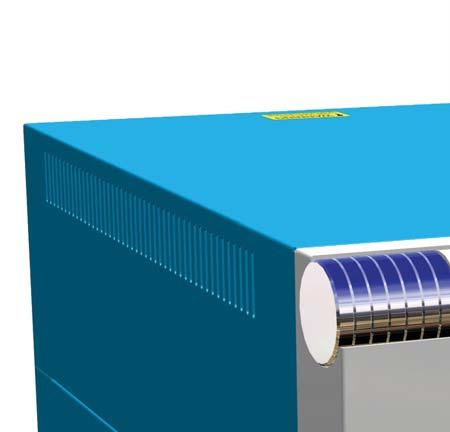
5 DME 5 Check your wiring Before you energize the system, pay special attention to how the power to your controller is wired and how it is connected to the mold. Lack of attention to detail causes errors such as: Incorrect wiring of controller's 3-phase circuit breaker Crossing heater supply feeds with thermocouple detection (although this error can be eliminated by the adoption of DME standard connections) In such cases wiring errors have caused equipment failure. DME Company cannot be responsible for damage caused to the controller due to customer wiring and/or connection errors. The Controller Cabinet The power supply to the control cabinet is via a strain-relief mounted cable gland plug and this may be wired in star or delta configuration. (Please check your specifications for details of which configuration has been configured.) An alarm output option is available for extending the alarm, or, perhaps, inhibiting the injection process. Controller Modules The controller uses six-zone modules that provide real time temperature control. Each card has three main components: Thermocouple input CPU Two control CPUs Multi-voltage output triacs Thermocouple Inputs The thermocouple inputs have preset responses for both J- and K- type thermocouples. The associated console provides means of selecting the sensor type which, in turn, sets the CPU linearization to match the selected thermocouple type. Central Processor Units (CPUs) The CPU provides the following facilities: Closed and open loop control of the zones Processes thermocouple and current readings to show on display Checks for alarm conditions, including excess current, incorrect thermocouple wiring, zone over temperature condition, low impedance between heater and ground, and generates alarm information for the display screen and alarm relay Controls the output power to the on-board triac using a number of self-tuning algorithms The card requires no analog calibration and is ready for use once set up from the display console. Output Triacs The controller card has six on-board triacs, one for each channel, that are capable of controlling heating loads of up to 15 amps peak. Power Supply The DC power supplies for the cards, data communications and an alarm output relay are all provided by a single power supply unit. This is located on top of the upper chassis panel. Isolate the Controller The main power switch is sufficiently rated to disconnect the total load current during switch On and switch Off. To prevent its operation, during maintenance, you can use a suitably-sized padlock, or similar device, to lock the switch in the Off position. Switching On and Off

6 6 DME The main power switch is a rotary switch found at the lower rear of the controller. It is sufficiently rated to disconnect the total load current during switch On and switch Off. Switching On When the controller is switched on, all zones go into Run mode automatically to start heating the tool. Switching Off (the Controller) We recommend using the console to shut down the heating load. Only use the main isolator to switch off a dormant controller. 1. Shut down the heating. On the main page, touch [Mode] 2. On the Mode page touch [Stop] 3. Shut down the Controller - use the main power switch to isolate all the power to the entire system Screen Layout and Navigation This part of the manual introduces you to the controller card to show what facilities are available and what information is available.


7 DME 7 Monitoring The main page has up to 12 zones displayed at maximum size. More zones can be shown with less information per zone. Control Side command buttons that change from page to page. Information Bottom row shows: Current Run Mode, Current Health Status,
8 8 DME Main Page Can be used for: Monitor observe zone condition Control Start/Stop & Boost/Standby immediately available. All others ( Standby, Shutdown, Stop ) available from [Mode] button Set select any one or more zones to get [Set] function to set or alter zone set-points or run modes. Monitoring Healthy Zone - shows: Zone Name Actual Temperature Scale + Set Temperature Applied Power Green text on Black background Warning Zone Deviation exceeds 50% of Alarm Setpoint Black text on Yellow background Alarm Zone Deviation exceeds Alarm Setpoint White text on Red background Fatal Error Problem detected (see page 47 for details) White text on Red background Zone Off Individual zone switched off
 use the [Display] button.")
![Use [Display] button to show 24 Zones - each zone](/docs-images/74/70824118/images/9-2.jpg "shows Title and Actual 48 Zones - each zone shows")
9 DME 9 Main Page Display To show less information and more zones (24-48 zones) use the [Display] button. Use [Display] button to show 24 Zones - each zone shows Title and Actual 48 Zones - each zone shows Actual
10 10 DME Control Start Stop and More Touch [Mode] on the top right brings a new set of command buttons. The next page offers four modes that are immediately available. RUN raise all the zones to their set operating temperature STANDBY Any zones with Standby Temperatures configured are reduced in temperature until the next command is given. START The system is started in a homogenous heat-rise in which all zones follow the slowest rising zone. It will switch to RUN when working temperature has been reached. SHUTDOWN The system is shut down in a homogenous heat reduction. It will switch to STOP when temperatures are less than 194 F. BOOST Any zones with Boost Temperatures configured are temporarily increased for a user-configurable period. When the boost period expires then zone temperatures return to their normal Set levels. STOP set all power levels to zero and lets the tool cool down to room temperature at its own rate. CANCEL returns to the main page Secondary confirmation is required to go into any mode other than that which is currently being used.
11 DME 11 Main Page Setting Temperature Touch one zone Touch another Touch [Range] Touch [Set], and, if prompted, enter the User Password. Use the key pad to type a new Temperature. Touch [Ent] to set the required temperature or [Bsp] to leave the page without making any changes. On return to main page, you see the new set temperatures. Note: They may individually show an Alarm if the new set temperature is significantly different than the present actual temperature but the system sees this as a temporary condition and will not show an overall Alarm condition until the tool has had time to attain the new set temperatures.


12 12 DME More Pages Tool Page Setup Tool Page Graph Page Zoom Page


13 DME 13 The User Interface Where the configuration of parameters requires a user interface then either a keyboard or a keypad is displayed. Keyboard this is offered wherever alphanumeric input is required such as entering a Password or a Tool Name. Full Keypad this has all functions available including Boost and Off switches plus Mode and Value options Numeric Keypad this has left-hand side grayed out and is used wherever numeric values only are required, such as Alarm Limits. Screen Saver There is an automatic function that dims the screen light by 50% after 5 minutes of user inactivity. Touching the screen anywhere will restore it to normal level.
14 14 DME Setting up your controller New Intelligent controllers leave the factory with their default settings as shown in this table below. Zone Temperature 0ºC or 0ºF Standby level 65ºC or 118ºF Boost level 0ºC or 0ºF Over temperature range 10ºC or 18ºF Under temperature range Maximum Power 85% For reconfiguring your controller to a new tool or environment, this chapter of the manual shows how to alter the various parameters to your preferred values and to save them. What is covered in this section Controller Settings settings that apply to the whole tool Zone Settings settings that apply to one or more zones Limits upper and lower alarm limits Boost the temperature increase when Boost Mode is selected Standby the temperature reduction when Standby Mode is selected

15 DME 15 Controller Settings (whole tool) Options When setting up a new tool you may consider setting these options that affect the overall performance of each tool. Controller settings may be different between different tools. For instance Tool 1 may display in Centigrade while Tool 2 may display in Fahrenheit Touch [Tool] to open the Tool page Touch [Setup] to open the Options page. If prompted, enter the System password. Touch [Config] to open the Controller Settings pages. Touch [Options] to open the Controller settings pages. (once there use the [PgUp] and [PgDn] buttons to view all Controller Settings) Settings on these pages include Input the single channel input (HA4 socket) may be configured to initiate either a Boost or Standby mode Scale Temperatures may be set to show as either Centigrade or Fahrenheit Power Display select the zone panel information to show percentage power or actual current Language select preferred user language Password Control allows you to disable passwords so that all operations may be available for open control Earth Leakage allows you to disable the display of Earth Leakage current and switch on, or off, the earth leakage control on the card. To select any option, such as Temperature scale is Deg C, touch that option to move the yellow selection indicator then touch [Enter] to confirm your selection or [Cancel] to leave the page without making any changes.

16 16 DME Global Settings (Tool Options) When setting up a new tool you may consider setting these options that affect the overall performance of each tool. Controller settings may be different between different tools. For instance Tool 1 may display in Centigrade while Tool 2 may display in Fahrenheit Touch [Tool] to open the Tool page Touch [Setup] to open the Options page. If prompted then enter the System password. Touch [Config] to open the Controller Settings pages. Touch [Global] to open the Global settings panel. Settings within this panel include Boost Time to enter the time for which the temperature will increase whenever the Boost mode is selected. (Note: Maximum Permissible Boost time is 500 seconds.) Maximum Temperature to limit the highest temperature to which any zone may be raised. (Note: the highest permitted Maximum Temp is 472 C or 882 F) Maximum Power to limit the highest power to which any zone may be raised. (Note: the highest permitted Maximum Power is 100%) Touch [Edit] to set any parameter or [Back] to close the panel and leave without making any changes.

17 DME 17 Zone Settings When setting up a new tool you may consider setting these options that are applicable on a zone by zone basis for any tool. Zone settings may be different between different tools. For instance Tool 1 may have manifold speeds set to Manual Slow while Tool 2 may have all zone speeds in Automatic. Touch [Tool] to open the Tool page Touch [Setup] to open the Options page. If prompted then enter the System password. Touch one or more zones to see new command buttons. Touch [Set] to view the next page Touch [Options] to open the Zone Settings pages. (once there, use the [PgUp] and [PgDn] buttons to view all Controller Settings) Settings on these pages include Alias uses the selected title to identify a group of zones as either Probes, Manifolds or Sprues. Not Used allows you to switch off spare zones so they do not show on the main page. Speed allows you to leave zones at Auto-detect setting or override to Slow, Medium or Fast should the auto setting not give the best performance Sensor allows you to match the controller to either J-type or K-type thermocouple. Touch [Cancel] to step back and return to main page. To select any option, such as Probe, touch that option to move the yellow selection indicator, and then touch [Enter] to confirm your selection or [Cancel] to leave the page without making any changes.


18 18 DME Monitoring Temperature Limits Your controller card monitors the actual temperature of each zone and verifies that the zone is operating within specific limits. Rather than fixed points of temperature, the High and Low Limits are set as deviations above or below the set point. If any zone temperature goes outside these limits, a visual alarm is shown which is extended to an alarm relay for external switching. Warn and Alarm Limits Although there is only one upper and one lower Alarm setting, each gives a visual warning at halfway point. If a High alarm is set to 10 deg then a Warning will show at 5 deg. The same is applicable for the under temp alarm level. Touch [Tool] to open the Tool page Touch [Setup] to open the Options page. If prompted then enter the System password. Select one or more zones either... Select one zone then another, then another, until you have all the required zones or Select the first zone, then the last, then touch [Range] to include all in between Touch [Set] to show the zone setting options. Touch [Limits] to open Alarm Limits panel. Within the Alarm Limits panel touch either High or Low [Edit] to reveal a keypad. The keypad allows you to enter the amount by which temperature must rise or fall to trigger an upper or lower temperature alarm. Note that temperature limits are applicable to the current scale. A High limit of 10 while in Centigrade would automatically become 18 when you change the scale to Fahrenheit. Touch [Cancel] to step back and return to main page.

![The Boost period is user-configurable and setting this is detailed on the following page. Touch [Tool] to open the Tool page Touch [Setup] to open the Options page.](/docs-images/74/70824118/images/19-5.jpg "If prompted then enter the System password.")
19 DME 19 Setting Boost Temperature The Boost Temperature may be individually set for each zone as described in the table below. When boost is activated, the controller will raise the zone temperature. Please note that, on a slow responding manifold, if you set a high boost temperature, the zone may not reach the set boost temperature before the boost time limit expires. The Boost period is user-configurable and setting this is detailed on the following page. Touch [Tool] to open the Tool page Touch [Setup] to open the Options page. If prompted then enter the System password. Select one or more zones either Select all the required zones or Select the first zone, then the last, then touch [Range] to include all in between Touch [Set] to show the zone setting options Touch [Boost]. Within the Boost panel, touch [Edit] to reveal a keypad. The keypad allows you to enter the amount by which the temperature will increase whenever the Boost mode is selected. Note: Maximum Permissible Boost temperature is 100 C or 180 F Touch [Cancel] to step back and return to main page.
20 20 DME Setting Standby Value Before you activate Standby function, you must first configure the amount. The Standby settings made here are only for Standby Temperature and are individually set for each zone. When standby is activated, those zones with any standby value configured will reduce their temperature. Touch [Tool] to open the Tool page Touch [Setup] to open the Options page. If prompted then enter the System password. Select one or more zones either Select one zone then another, then another, until you have all the required zones or Select the first zone, then the last, and then touch [Range] to include all in between. Touch [Set] to show the zone setting options Touch [Standby] to open the Standby panel. Within the Standby panel, touch [Edit] to reveal a keypad. The keypad allows you to enter the amount by which the temperature will reduce whenever the Boost mode is selected. Note: Maximum Permissible Standby temperature is 100 C or 180 F. Touch [Cancel] to step back and return to main page.
![DME 21 Set Zone Temperatures and save to Tool Bank Touch one zone Touch another Touch [Range] Touch [Set], and, if](/docs-images/74/70824118/images/21-0.jpg "prompted, enter the System Password. Use the key pad to select a new Temperature.")
![Touch [Ent] to set the required temperature or [Esc] to leave the page without making any changes.](/docs-images/74/70824118/images/21-1.jpg "Note: Maximum permissible temperature is 472 C or 882 F On return to main page you see new set temperatures (here shown")
21 DME 21 Set Zone Temperatures and save to Tool Bank Touch one zone Touch another Touch [Range] Touch [Set], and, if prompted, enter the System Password. Use the key pad to select a new Temperature. Touch [Ent] to set the required temperature or [Esc] to leave the page without making any changes. Note: Maximum permissible temperature is 472 C or 882 F On return to main page you see new set temperatures (here shown in Warning because they are currently higher than actual temperature)

![touch [New] Enter Tool Name and Touch the [Enter] button Note:](/docs-images/74/70824118/images/22-2.jpg "Maximum Permissible tool name is 12 characters long.")
![Touch [Load] and [OK] to accept new toolbank.](/docs-images/74/70824118/images/22-4.jpg "Return to Tool page to see new tool with new name.")
22 22 DME Save new Tool to Tool Bank (From previous page) Touch [Tool] to open the Tool Page Touch any blank tool slot then touch [New] Enter Tool Name and Touch the [Enter] button Note: Maximum Permissible tool name is 12 characters long. Touch [Load] and [OK] to accept new toolbank. Return to Tool page to see new tool with new name. Touch [Back] to return to main page with new tool saved.
23 DME 23 Password Options When you first use your touch screen controller you find, as you scroll through the screens, that some functions are protected by password access. Wherever a password is required then a keyboard is displayed where you can enter the required password. Three levels of control If the User Password option is set to [Enabled] then there are three levels of control 1) Open Level includes various functions that need no password such as Start and Stop. 2) User is a Level 1 password which gives low level access to: Switch the tool on and off Alter temperatures Select different tools 3) System is a Level 2 password which gives high-level access to: All user-level functions Reconfigure the settings for a new tool Store and load new tool settings to/from a memory stick Password Disabled If the Password option is set to [Disabled] then all User and System functions become Open Level and no longer require any Password to access. About password active times After you key in a password, access is possible while you continue to input data. Each key-touch resets the timer but, when no more input is detected, it times out and then denies unauthorized access.
![24 DME Setting Password Control Touch [Tool] Touch [Setup] Enter password (if enabled) Touch [Config] Touch [Options] Touch [PgDn] (twice) to see Password Control](/docs-images/74/70824118/images/24-4.jpg "Select [Enable] to have a higher level password control or [Disable] for open control.")
24 24 DME Setting Password Control Touch [Tool] Touch [Setup] Enter password (if enabled) Touch [Config] Touch [Options] Touch [PgDn] (twice) to see Password Control Select [Enable] to have a higher level password control or [Disable] for open control. Touch [Enter] to accept the setting or [Cancel] to step back and return to main page.
25 DME 25 Password Application Table Here is a detailed list of what level of password is required for various functions on the different pages. PAGE/SCREEN NO PASSWORD REQUIRED TO LEVEL1 (USER) PASSWORD REQUIRED TO: LEVEL 2 (SYSTEM) PASSWORD REQUIRED TO: Main Run/Stop/Change Modes. Change Display options. Go to Zoom or Graph page Set (Alter temperatures or modes) Zoom View only - so no other function except zone up or down Graph View only - so no other function except zone up or down Tools View available tools Load, Save, Backup Restore, Delete New (Create new tools) Tools - Setup Set, Config (Change any values) Password Security Every machine leaves our factory with two levels of password protection (these are provided in the front of this manual). We recommend that you change these, as soon as possible, and save them in another location to establish your own security.
26 26 DME Running your controller Running your controller is concerned with everyday use of the controller for normal production use. This is considered as selecting an appropriate run mode for the machine according to whether the tool is working or waiting. It may also be necessary to make changes to the heater temperatures. Using the graphical display of recent performance may help such decisions. What is included in this section: Run Modes Manual Mode (open loop control) Slave Mode Standby Mode Boost Mode how to apply a short increase Changing Set Temperature Alarms
27 DME 27 Operating Modes (Start, Stop, Boost and more) Touch [Mode] on the top right brings a new set of command buttons. RUN raise all the zones to their set operating temperature STANDBY - Any zones with Standby Temperatures configured are reduced in temperature until the next command is given. START The system is started in a homogenous heat-rise in which all zones follow the slowest rising zone. It will switch to RUN when working temperature has been reached. SHUTDOWN The system is shut down in a homogenous heat reduction. It will switch to STOP when temperatures are less than 90 C. BOOST Any zones with Boost Temperatures configured are temporarily increased for a user-configurable period. When the boost period expires then zone temperatures return to their normal Set levels. STOP set all power levels to zero and lets the tool cool down to room temperature at its own rate. CANCEL returns to the main page Secondary confirmation is required to go into any mode other than that which is currently being used. More about Startup and Shutdown STARTUP the system measures the heat gain of every zone and automatically holds back the faster (probe) zones to the same rise rate as the slowest rising zone. This ensures that you get a homogenous rise across the whole tool. SHUTDOWN the system operates in a similar but reverse method to startup. It switches off the slowest zone and sets the set temperature of all others to be 30 lower. This ensures that you get a smooth uniform cool down across the whole tool.

28 28 DME Boost Mode Individual Zones This mode provides a means of temporarily boosting the zone temperature for any one or more zones for a preset (user-configurable) period. Touch any one or more zones Touch [Set] and enter password to show the keypad Touch [Boost] to raise the set level of the selected zones The screen reverts to main display where you can see the boosted temperature. The zone returns to normal temperature after the preset Boost Time.
29 DME 29 Switching individual zones off Touch any one or more zones Touch [Set] and enter password to show the keypad Touch [Off] to switch off the selected zones The screen reverts to main display where you can see the selected zone switched off. If you select the same zone and touch [Set] the keypad will display On instead of Off in order to revert the zone to normal duty
30 30 DME Changing or Setting Zone Temperatures Touch one zone Touch another Touch [Range] Touch [Set] and enter password. (Note: temperature and power settings have preset limits as described on page 16.) To Set a new temperature - touch [Set] -orto Raise the overall temperature - touch [Add]. -orto Lower the overall temperature - touch [Sub]. and enter a value. On return to main page, you see the new set temperatures. Note: They may individually show an Alarm if the new set temperature is significantly different to the present actual temperature but the system sees this as a temporary false condition and will not show an overall Alarm condition until the tool has had time to attain the new set temperatures.


31 DME 31 Changing to Manual Mode Manual mode (open loop working) can be simply selected as an alternative to running in Auto (closed loop). Touch one zone Touch another Touch [Range] Touch [Set] and enter password Touch [Man] Key in manual percentage. Touch [Ent].


32 32 DME Slave Mode Slave mode is an alternative to Manual and can be selected if one zone has a faulty thermocouple. The Slaved zone then mimics the same power output as the healthy zone and, provided that they had been running at a similar power level previously, the slaved zone will hold a similar temperature. Touch any zone and see new command buttons Touch [Set] and enter password Touch [Slave] Key in the number of a healthy zone Touch [Ent] Return to Main page and see first zone now slaved to second selected zone. The Slaved zone now displays the number of the zone that it has been slaved to.
33 DME 33 Alarms Whichever page may be active; there is a common Mode and Status window at the bottom of the page. If your controller is switched on and running normally then the left hand Mode window will show RUN and the opposite Status window will show NORMAL. Mode Window If the controller is manually switched out of RUN mode then the Mode window shows the selected function, and is seen flashing, on and off. The table below lists the different displays: RUN BLACK TEXT IN WHITE BOX ALL CONTROL ZONES ARE WORKING NORMALLY STOP White text in Blue box The System has been shut down and the heaters are at room temperature. STANDBY STARTUP Yellow text in Black box Any zones with Standby Temperatures configured have been reduced in temperature until the next command is given. The system has been started in a homogenous or staged heat-rise. It will switch to RUN when working temperature has been reached. SHUTDOWN The system has been shut down in a homogenous or staged heat fall. It will switch to STOP when room temperature has been reached. BOOST Black text in Yellow box Any zones with Boost Temperatures configured are being temporarily raised. (manual request) Status Window The right-hand Status window shows NORMAL if all the zones are at their set temperature and no faults have been detected. If any zone detects a fault then the Status window changes its display and color as detailed below: NORMAL GREEN TEXT IN BLACK BOX CONTROLLER IS RUNNING NORMALLY WARNING Black text in Yellow box A zone s temperature exceeds the warning limits ALARM White text in Red box This shows either a Fatal Error or a zone s temperature exceeds alarm limits Note that the status alarm is only active when in Run Mode so systems, whose temperature rises slowly will not raise false alarms. Once they switch over to Run mode at their set temperature then the alarm becomes active.
34 34 DME Identifying Zone Alarms Normal Zone This shows a healthy zone Green text on Black background Warning Zone This shows a first stage warning Black text on Yellow background Alarm Zone This shows a second stage alarm White text on Red background Fatal Error an abbreviated Error message. (for a list of all Error messages see page 47) White text on Red background Alarm Extension There is a row of red LEDs above the console which acts as an Alarm Repeater which illuminates whenever the console generates an alarm. This may not mimic the Status window for instance zones may individually show an Alarm if the new set temperature is significantly different to the present actual temperature but the system sees this as a temporary condition and will not show an overall Alarm condition until the tool has had time to attain the new set temperatures. Beacon and Sounder Extension A Beacon and Sounder extends any second stage temperature alarm or fatal error alarm. Fixing the alarm condition automatically extinguishes the beacon/sounder. A key switch is also provided to mute the sounder at any time. Note however, that no reminder is given to show that the sounder is muted when the system is healthy. Re-occurrence of subsequent alarm conditions will cause the beacon to light but not create an accompanying audible alarm. Card Indicators Zone Control Cards have two LED indicators that give a state-of-health display that can be seen on the front edge of the card when the cabinet door is open. SCAN this LED flashes briefly as the controller interrogates each card in sequence. FAULT Should normally be extinguished. It lights to show that a fault has been detected on the card which may be due to a T/C or wiring problem.
35 DME 35 Customizing your controller Your controller has a dedicated Tool Bank which enables fast adaptation to different circumstances. It has 12 available positions that can be individually configured, named, saved and recalled whenever the tool or job changes. What is included in this section: Using the ToolStore Page Renaming an Existing Tool Loading Tool settings Saving Tool settings Deleting a Tool Backing-up Tool settings Restoring Tool settings
36 36 DME Using the tool store page The initial window shows the 12 tool slots which may be used to save different settings for different tools. The tool that is currently loaded and being used is shown with a pink background here seen as the first tool in the top row. Other tool slots that have saved tool settings can be identified by seeing a name in that box. Touch and select another tool slot to see that border appear blue but it does not become the tool in use until you touch [Load] and confirm [Yes] Touch [Cancel] to return to the previous page. Touch [Setup] and enter system password to go to tool configure options Tool Options page offers more control to setup the tool (which is fully described in the setup chapter)

 Saving tool settings Whenever you make any changes to a currently loaded")
37 DME 37 Loading tool settings Note that the operating mode for the controller cabinet remains unchanged by loading another tool. So, if your controller is in Run mode and another tool setting with different temperatures is selected, and loaded, then the tool will immediately change to run at the new incoming temperature settings. Select the desired tool. Touch [Load] and enter System Password Touch [OK] (or [Cancel] to exit) Saving tool settings Whenever you make any changes to a currently loaded tool, any changes that you make are saved shortly after your last touch of the screen.

38 38 DME Saving changed tool settings If you wish to make a different selection of tool settings and save them for use at another time, you must first create a copy of your current settings as a different tool name, load that copy and make your changes there. Select a spare blank tool tab Touch [Save] and enter System Password Enter a new tool name and touch [Enter]. Return to Tool page and see new tool with new name - touch [Load] Touch [OK] to confirm Once the new tool is current leave this page and make all necessary changes. When you have finished then you have an alternative tool. You can, if you wish, return to this page and reload the original tool to get back to your original settings.

39 DME 39 Deleting a tool Once you have deleted a tool there is no way to recover its previous settings. Take care that you are deleting the correct tool. Note there are two safeguards to check that you delete the correct tool. Select tool to be deleted Touch [Delete] If you try to delete the currently loaded (active) tool a Warning Panel stops the selection. Return and select correct tool, then touch [Delete] once more. At this point a safeguard asks you to confirm your deletion. Touch [OK] to confirm or [Cancel] to return without deleting the selected tool After confirmation, return to the Tool page to see extra-temp tool now deleted.
40 40 DME Backing up tool settings (with optional USB port) Backing up tools is a means of saving tool settings to an external media which may be kept in a safe place for secure recovery or transfer to another controller for use elsewhere. Insert storage media then wait about 10 seconds until the USB memory is ready to use. Select the tool to Backup Touch [Backup] Provided a good USB memory stick is found inserted, the tool settings are saved. If there is a problem, a Warning message is displayed try using a different USB stick. Wait about 10 seconds until data has been written and operation is complete then remove storage media


41 DME 41 Restoring tool settings (with optional USB port) If there is any information stored in a selected tool bank or slot, this process overwrites new information into that position. There is an option within this sequence to restore either all of the stored tools or just one selected tool. Insert the storage media then wait about 10 seconds until the USB memory is ready to use. Select a blank tool tab Touch [Restore] Wait about 10 seconds until data has been written and operation is complete then remove the media
42 42 DME Maintaining your controller Maintaining your controller is all about keeping it in order, checking records and settings and running self-diagnostic checks. There are no user serviceable parts inside the touch screen controller and, in the unlikely event of equipment failure you should return the unit for attention. What is included in this section Self Diagnostic Tests System Diagnosis Results Servicing and Repairing your Controller
43 DME 43 Self diagnostic tests The Controller has a diagnostic testing tool which allows you to check that every zone is functioning correctly. It is the correct routine that you should use: As an acceptance check To see that a new tool is wired up correctly As a maintenance aid, to check that a working tool is functioning correctly How the test works The following describes the test sequence to show how it works. 1) It applies 10% power and observes that: a) the temperature of the zone under test does not reduce further which would indicate a reversed thermocouple on that zone. b) the zone under test rises sufficiently to a set level if not it increases the applied power and searches again for that temperature rise. It continues to raise the power and look for the expected temperature until a set timer expires. If it does not see the right temperature within the right time, then the zone has failed. c) no other zone rises by as much as the first set temperature, which would indicate cross-wiring between the zone under test and another thermocouple. d) no other zone rises significantly which would indicate excessive thermal conduction between adjacent zones. 2) After completing the test on the first zone, the routine then moves to subsequent zones until all have been tested. 3) At the end of the test it builds a list of results to show how the test progressed.

![Touch [Tool] Touch [Setup] then enter the System Password if requested Touch [Test] Touch [OK] to start or [Cancel] to go back The](/docs-images/74/70824118/images/44-3.jpg "Mode window then shows Testing and the first zone Temperature display will read Test.")
![Touch [Stop] at any time to end the test prematurely. Touch [Skip] at any time to skip a zone and move on to the next.](/docs-images/74/70824118/images/44-4.jpg "If you touch [Cancel] the test will finish and no test results will be displayed At the end of the test Sequence the Controller")

44 44 DME Running a Self Diagnosis test The diagnostic routine may be performed at any time that the controller is connected to the tool, provided that it is not in use for production. Touch [Tool] Touch [Setup] then enter the System Password if requested Touch [Test] Touch [OK] to start or [Cancel] to go back The Mode window then shows Testing and the first zone Temperature display will read Test. Touch [Stop] at any time to end the test prematurely. Touch [Skip] at any time to skip a zone and move on to the next. If you touch [Cancel] the test will finish and no test results will be displayed At the end of the test Sequence the Controller will build a test result page to show how the test progressed for each zone. Any zone that fails to test successfully is highlighted by a red button marker followed by a brief explanation or a code to show why it failed. At the end of the test you can touch the [Save] button to export the results to an external USB flash stick as a.csv file. Touch [Cancel] to leave the test page and return to the Tool page
45 DME 45 System diagnosis results The Test page retains information about any test that is run. You can scroll the screen to view all the results or touch [Print] for a hard copy. Interpreting the Test Results Satisfactory Test If the diagnostic test finds no fault with any zone then the message Zone Test OK is displayed against every zone. Unsatisfactory Test If the test detects any problems then it displays an error message against the particular zone. Below is a complete list of the various messages along with further detail and possible causes. User Skipped You skipped the test for this zone by pressing [Skip] while it was being tested. User Stopped You aborted the test by pressing [Stop]. T/C Thermocouple detected as being open circuit. Check thermocouple wiring for displayed zone. FUSE - Check card fuse. This message is also displayed if the zone was set to use an off board triac that was not installed. N.B. Off board triacs have their own fuse. No Mains Sync. Pulse This is probably due to an error in the supply wiring. N/Z No card was detected in the rack at the slot identified with the displayed zone. Heating Test Failed Temperature did not rise by the set number of degrees within the heating period. This may be caused by an open circuit heater, a pinched, shorted or dislodged thermocouple. REV Temperature appeared to be decreasing when power was applied. Below 0 or Reversed T/C May be caused by a reversed thermocouple. Also, in the unlikely event that the test was carried out at an ambient temperature below 0 C, the controller would not work with the resulting negative temperature readings. Failed to React Correctly Unexpected results. This message is followed by further error messages. T/C Interaction with zone NN? A different zone(s) than the one being tested had an unacceptable rise in temperature (greater than Bad Rise set in Test Values). Indicates faulty T/C positioning or close zone proximity. Heater/TC Common with zone NN? Cross-wiring fault between displayed zones. Could be either the Heater or the thermocouple wiring at fault. Servicing and repairing your controller Always isolate your controller at source before you open the unit to inspect it or replace fuses. When it comes to machine maintenance there is very little that you need to do to look after it. Replacement parts We do not expect that you will need to repair any controller parts at board level, other than fuses. In the unlikely event of any board failure please contact DME Customer Service ( or returns@dme.net) for return information. Cleaning and Inspection Any excess dust that has entered the cabinet may be removed with a light brush and vacuum cleaner. External cables should be checked to see that there is no damage to the flexible conduit, plugs or sockets. If the flex has been squashed, if there is visible damage, or if there are any exposed conductors, then for your own safety, it must be replaced. If the equipment is subject to vibration then we recommend that you use an insulated screwdriver to check that no terminals have become loose.
46 46 DME Troubleshooting Individual Card Diagnostics The control system has several features which provide a diagnosis of faults in the control system, the tool heaters and thermocouple sensors. If a zone temperature is seen to deviate from the actual setting beyond the alarm limits then the display will change to White text in Red box and generate a remote alarm The following is a list of alarm conditions that may be detected and which will also activate the output contacts. ERR! GND REV T/C ERROR MESSAGE CAUSE ACTION FUSE/LINE This message flashes between the two alarms either fault may be applicable Little or no temperature rise has been detected in that zone. When the console starts to apply power it expects to see an equivalent heat rise at the thermocouple. If the Thermocouple has been trapped and pinched elsewhere in the tool or cable then it cannot see the full heat rise that occurs at the tip. If left uncorrected, there is a danger that the zone could overheat and damage the tip. Instead the circuit maintains the output at whatever level it reached when the monitor circuit detected the fault. The system has detected an earth fault. The card has detected an abnormal input at the T/C termination that indicates a shorted or reversed thermocouple. An open circuit thermocouple has been detected and no autoresponse has been selected in the T/C Open Error column of the Setup page. EITHER the output fuse for that zone has failed. Note: A fuse can only fail due to a fault external to the controller. Identify and rectify the fault before replacing the fuse. Note: The fuse detection circuit requires a continuous low level current through a high impedance bleed resistor to maintain the alarm condition. As a result the load circuit is still connected to the main voltage supply and it is not safe to attempt to repair or replace the fuse without first isolating the circuit. If the fuse in question is mounted on a control card then it is safe to unplug the board in order to isolate the circuit and replace the fuse on the card. OR No main supply synchronization pulses being received. The three-phase supply is used in a cross-over detection circuit to generate timing pulses for accurate phase control and firing the triac. If the phase detection fails on one or two phases then there is no pulse to use to measure phase angle and the LINE error message is generated. Meanwhile, all circuits on the healthy phases will continue to work normally. Check thermocouple wiring, it may be reversed. Heater wiring may be faulty or element may be open circuit. Check your heater wiring for a low impedance path to ground. If the REV alarm persists then you should switch off the controller and investigate the offending zone. Alternatively you could slave the offending zone to a good zone until you have time to clear the fault. For immediate recovery you can either slave that control zone to an adjacent zone or change to open loop control. Make a note of the above action so that when the controller is free you can check to see whether the input fuse on the control card has ruptured. If the fuse is good then you may need to check the wiring for faults or even replace the thermocouple. Replace the fuse with one of the same rating and type, i.e. High Rupture Current load fuse. The blown fuse is located on the control card. There is a phase detection circuit on each card and a common phase detection circuit on all other controller types. Although a fault in such circuits may cause the LINE error message, such fault is very rarely seen. The most common error is either the absence of one phase or, if a plug has been re-wired incorrectly, a swapped phase and neutral. If a LINE error message occurs then switch off and isolate the controller then check supply wiring for presence of all three phases.
47 DME 47 Other possible fault Conditions Rapid Temperature Fluctuations The most likely cause of temperature fluctuations is extraneous voltages being picked up by the thermocouple cable, i.e. common mode. This may be due to poor grounding of the tool or, a faulty shielded thermocouple wire or, alternatively, a faulty heater. We recommend that all earth connections be tested. Ground Fault Detection The Ground fault detection detects any fault caused by ground leakage current. Ground faults can be caused if a tool has been idle for some time and moisture has gotten into one heater. It may be possible to identify the heater and repair the faulty zone by using the adjacent heaters to heat it up and dry it out, thus fixing the original problem. Module Removal To remove a control module from its slot, unscrew four corner screws first. There is no need to switch off the main supply. However, if operational requirements allow, the cabinet may be isolated. The shrouded terminals on the motherboard are live unless the power supply is switched to OFF. ITS Fuses There is a Miniature Circuit Breaker that offers general over-current protection for the complete unit. Supplementary Fuses All the supplementary circuits (console supply, power supply, fans) are protected by a pair of fuses which are fed from the upper and lower supply busbars. These are din-rail mounted and can be found inside the left side cover (viewed from the front) of an ITS-48 and under the cover at the top on an ITS-12. Class Rating 20mm Glass Fuse Antisurge (ABS Fuse) 10 Amps Controller Cards The current controller card has protection fuses for both the T/C input and for the heating load output. Input Fuse Type: Surface-mount quick-blow If the module shows a T/C alarm then this may indicate that the input fuse has ruptured. The card may be easily removed and the fuse changed. Item Number Fuse Rating RPM Amps Output Fuse Type: HRC High Speed If the module shows a FUSE alarm then the card may be easily removed and the fuse changed. Only use Ceramic Body Fuses on Control Cards; NEVER use glass bodied fuses. Item Number Rating RPM Amps NOTE: If you find that any fuse has ruptured then please make sure that you replace the faulty fuse for a new one with identical characteristics.
48 World Headquarters DME Company LLC Stephenson Highway Madison Heights, MI toll-free tel tel toll-free fax web DME of Canada Ltd Northwest Drive Mississauga, Ontario Canada L4V 1J toll-free tel tel toll-free fax DME Europe DME Belgium C.V.B.A. Industriepark Noord B-2800 Mechelen Belgium tel fax ITS-10/13
User Manual DME Company
 SmartSeries TSM1512 Microprocessor-Based Temperature Control Module With Touch Screen Color Display User Manual DME Company DME Company LLC TSM1512 SmartSeries Hot Runner Controller Page 1 of 44 SAFETY
MT Controller User Manual
 MT Controller User Manual Original Instructions Mold-Masters (2007) Limited A Milacron Company REMOVE AND KEEP THIS SHEET SOMEWHERE SAFE MT Controllers come with a fixed password which is entered via
User s Manual. TIGER S EYE E-Series Mark V Jockey. TIGERFLOW Systems, Inc Mint Way Dallas, Texas
 User s Manual TIGER S EYE E-Series Mark V Jockey TIGERFLOW Systems, Inc. 4034 Mint Way Dallas, Texas 75237 214-337-8780 www.tigerflow.com TABLE OF CONTENTS Introduction... 4 Sequence of Operation... 5
ZX1e ZX2e ZX5e. Document No Issue 01 user manual
 ZX1e ZX2e ZX5e Document No. 996-130 Issue 01 user manual MORLEY-IAS ZX2E/ZX5E Fire Alarm Control Panels Table of Contents 1 INTRODUCTION... 4 1.1 NOTICE... 4 1.2 WARNINGS AND CAUTIONS... 4 1.3 NATIONAL
B-40/B-41 Modulating Temperature Controller
 INSTALLATION & OPERATING INSTRUCTIONS B-40/B-41 Modulating Temperature Controller For Raytherm Boilers & Water Heaters H2 514-4001 WH2 2100-4001 Catalog No. 5000.70 Effective: 12-21-11 Replaces: NEW P/N
Digi-Sense TC9000 Advanced PID and On/Off Temperature Controller with Thermocouple Input
 User Manual 99 Washington Street Melrose, MA 02176 Phone 781-665-1400 Toll Free 1-800-517-8431 Visit us at www.testequipmentdepot.com Digi-Sense TC9000 Advanced PID and On/Off Temperature Controller with
APC BC300 Series 40kW 208/450/480V User Guide
 APC BC300 Series 40kW 208/450/480V User Guide Copyright 2002 APC Denmark ApS This manual is subject to change without notice and does not represent a commitment on the part of the vendor Thank You Thank
Operating & Maintenance Manual. Alert-4 Ethernet LCD Master Alarm
 Operating & Maintenance Manual Alert-4 Ethernet LCD Master Alarm w w w. a m i c o. c o m Contents User Responsibility 4 Introduction 4 Features 5 Description of the Alarm 5 Shipment Details 5 The Alarm
Beacon 200 Gas Monitor Operator s Manual. Part Number: RK Released: 6/6/08
 Beacon 200 Gas Monitor Operator s Manual Part Number: 71-2102RK Released: 6/6/08 Table of Contents Chapter 1: Introduction.................................................3 Overview.............................................................3
HIGH EFFICIENCY FIRETUBE CONDENSING GAS BOILER
 This manual must be left with owner and should be hung on or adjacent to the boiler for reference. US HIGH EFFICIENCY FIRETUBE CONDENSING GAS BOILER MODELS CHS-85 through CHS-399 APPENDIX A CONTROLLER
Refrigeration Controller Operator s Manual (HRC) PO Box 6183 Kennewick, WA
 PO Box 6183 Kennewick, WA") Refrigeration Controller Operator s Manual (HRC) PO Box 6183 Kennewick, WA 99336 www.jmcvr.com 1-509-586-9893 Table of Contents TABLE OF FIGURES...1 OVERVIEW OF THE HRC CAPABILITIES...2 INSTALLATION AND
Refrigeration Controller Operator s Manual (HRC) PO Box 6183 Kennewick, WA 99336 www.jmcvr.com 1-509-586-9893 Table of Contents TABLE OF FIGURES...1 OVERVIEW OF THE HRC CAPABILITIES...2 INSTALLATION AND
Altanium Temperature Controllers
 Designed to provide the industry s most consistent part quality Benefits 2 to 254 zones of control Simple and intuitive operation Interchangeable cards and interfaces across the entire product line Active
SITC-15 Temperature Controller GITC-15 Temperature Controller Mainframe Operation Manual
 SITC-15 Temperature Controller GITC-15 Temperature Controller Mainframe Operation Manual SITC Quick Reference:... GITC Quick Reference:... Basic Operation Procedures:. SITC Parameters:... GITC Parameters:...
User Manual. Dryer Controller M720
 User Manual Dryer Controller M720 Hardware version 1.00 Software version 1.00 Preliminary version Manual M720 Dryer controller Page 1 of 42 Document history Preliminary version: - Created in April, 2009
MODEL SF-10 CONTROL OPERATION AND INSTRUCTION MANUAL
 MODEL SF-10 CONTROL OPERATION AND INSTRUCTION MANUAL The SF-10 Temperature Control () is an efficient boiler operator with a digital LCD display with backlight, a boiler pump output, and an alarm. The
Interactive Fire Control Panel IFS7002 four signal loops Instruction Manual
 Interactive Fire Control Panel IFS7002 four signal loops Instruction Manual Revision 6/01.17 Contents 1. Introduction... 6 2. Terminology... 6 3. Function... 8 4. Technical data... 8 4.1. Physical configuration...
Installation, Operating and Maintenance Manual
 STATUS ZONES CONTROLS FIRE FAULT DISABLED FIRE 1 2 3 4 5 6 7 8 TEST FAULT DISABLED 1 5 BUZZER SILENCE RESET 1 2 TEST 2 6 LAMP TEST 3 SUPPLY 3 7 SYSTEM FAULT 4 8 SOUNDERS ACTIVATE/ SILENCE 4 FAULTS INSTRUCTIONS
Dryer Master DM510 Commissioning Guide
 COMMISSIONING GUIDE Dryer Master DM510 Dryer Moisture Systems Inc. 640 Superior Drive Waterloo, Ontario Phone 519.725.4700 Fax 519.885.4300 USA & Canada Toll Free 1-888-318-0009 E-mail: info@dryermaster.com
Interactive Fire Control Panel IFS7002 one signal loop Instruction Manual
 Interactive Fire Control Panel IFS7002 one signal loop Instruction Manual Revision 4/01.17 Contents 1. Introduction... 6 2. Terminology... 6 3. Function... 8 4. Technical data... 8 4.1. Physical configuration...
Technical Manual. Level Alarm Unit CARLA & WIDS
 CARLA & WIDS Technical Manual SAS au Capital de 2 158 244-444 871 933 R.C.S. Bourges - APE : 2651B Headquarter : 9, rue Isaac Newton - 18000 Bourges - France Technical Manual CARLA for Tankers Cargo Tanks
Dryer Controller M720
 User Manual Dryer Controller M720 Hardware version 2.00 Software version 2.00 Manual M720 Dryer controller Page 1 of 60 Document history Preliminary version: - Created in April, 2009 Hardware Version 2.00,
ModSync Sequencing System Installation & Operation Manual. For use with Fulton Steam Boilers.
 ModSync Sequencing System Installation & Operation Manual For use with Fulton Steam Boilers. Revision 3.0 8/21/2008 - 2 - Table of Contents Introduction Page 4 Features Page 4 Sequence of Operation Page
User Manual. Digi-Sense TC9500 Advanced Multiparameter Temperature Controller with Thermocouple, Thermistor, and RTD Inputs
 User Manual Digi-Sense TC9500 Advanced Multiparameter Temperature Controller with Thermocouple, Thermistor, and RTD Inputs Models 89800-03 and 89800-04 THE STANDARD IN PRECISION MEASUREMENT Table of Contents
i.c³ User Guide For Helmer i.series Ultra-Low Freezers A/A
 i.c³ User Guide For Helmer i.series Ultra-Low Freezers 360175-A/A Document History Revision Date CO Supersession Revision Description A 18 APR 2014* 9275 n/a Initial release. * Date submitted or change
PNC 1000 SERIES 2, 4, 8 Zone Fire Alarm Control Panel
 PNC 1000 SERIES 2, 4, 8 Zone Fire Alarm Control Panel INSTALLATION, OPERATION AND MAINTENANCE MANUAL Version: CN-PM-1000.VER1.1-12/2012 EN54 INFORMATION In accordance with EN 54-2 clause 13.7, the maximum
Flopurge TS. Operation Manual
 Flopurge TS Operation Manual Part Number 079-0204 Spectron Gas Control Systems United Kingdom Unit 4, Herald Court, University of Warwick Science Park, Coventry, CV4 7EZ +44 (0)24 7641 6234 sales@spectron-gcs.com
HBC-4301 Hot Bonding Controller. Operators Manual
 HBC-4301 Hot Bonding Controller Operators Manual January, 2006 TABLE OF CONTENTS TABLE OF CONTENTS... 1 1. GETTING GOING FAST... 7 2. INTRODUCTION... 9 3. SPECIFICATIONS... 11 3.1 HARDWARE SPECIFICATIONS...
ANALOX SENSOR TECHNOLOGY LTD ANALOX DD1101 INSTALLATION & OPERATION MANUAL
 ANALOX SENSOR TECHNOLOGY LTD ANALOX DD1101 INSTALLATION & OPERATION MANUAL SAFETY WARNING Please Refer to the Safety Warning in Section 7.1 regarding the chemicals in the oxygen sensor Analox Sensor Technology
Flostop TS D7E and A8E. Operation Manual
 Flostop TS D7E and A8E Operation Manual United Kingdom Spectron Gas Control Systems Ltd, Unit 4, ATU1, University of Warwick science Park, Coventry, +44 (0) 24 7641 6234 sales@spectron-gcs.com Germany
VERTEX VT10 SERIES PID OPERATION MANUAL MICROPROCESSOR BASED PID CONTROLLER
 1 VERTEX VT10 SERIES PID OPERATION MANUAL MICROPROCESSOR BASED PID CONTROLLER 1. INTRODUCTION This manual contains information for the installation and operation and tuning of our Vertex VT10 series self-tuning
Smart Temp. Model
 Smart Temp Model 42-160 SINGLE STAGE PROGRAMMABLE THERMOSTAT 1 Heat / 1 Cool Single Stage Thermostat. 5+2 Programmable, Compatible with Gas Heat & Heat Pump System Installation and Operation Manual SPECIFICATIONS:--------------------------------------------------------------------------------
QTC15 Temperature Controller Operation Manual
 PLASTIC PROCESS EQUIPMENT, INC. QTC15 Temperature Controller Operation Manual PLASTIC PROCESS EQUIPMENT, INC. PPE WEST 6385 Montessouri Street, Las Vegas, Nevada 89113 702-433-6385 800-258-8877 Fax: 702-433-6388
User Manual. Digi-Sense TC9600 Advanced Multiparameter Temperature Controller with Thermocouple, Thermistor, and RTD Inputs
 User Manual Digi-Sense TC9600 Advanced Multiparameter Temperature Controller with Thermocouple, Thermistor, and RTD Inputs Models 89800-13 and 89800-14 THE STANDARD IN PRECISION MEASUREMENT Table of Contents
Instruction manual MTL process alarm equipment. October 2016 CSM 725B rev 2 MTL RTK 725B. Configuration Software Manual
 Instruction manual MTL process alarm equipment October 2016 CSM 725B rev 2 MTL RTK 725B Configuration Software Manual SECTION 1 - INTRODUCTION... 5 Basic Requirements... 5 SECTION 2 - SOFTWARE INSTALLATION...
Tempco PCT-3000 Series Temperature Control Console with Relay Output for Heating or Cooling Applications
 Instruction Manual Tempco PCT-3000 Series Temperature Control Console with Relay Output for Heating or Cooling Applications Manual PCT-3000 Revision 9/2014 The PCT-3000 series control console incorporates
Carbon Monoxide Transmitter
 Introduction The CO Transmitter uses an electrochemical sensor to monitor the carbon monoxide level and outputs a field-selectable 4-20 ma or voltage signal. The voltage signal may also be set to 0-5 or
REPEATER FS5200R INSTRUCTION MANUAL
 REPEATER FS5200R INSTRUCTION MANUAL Instruction Manual Page1 CONTENTS 1. Introduction... 3 2. Function... 3 3. Technical data... 3 4. Contents of delivery... 4 5. General information... 5 6. Duty Mode...
GTC15 Temperature Controller Operation Manual
 PLASTIC PROCESS EQUIPMENT, INC. GTC15 Temperature Controller Operation Manual PLASTIC PROCESS EQUIPMENT, INC. PPE WEST 6385 Montessouri Street, Las Vegas, Nevada 89113 702-433-6385 800-258-8877 Fax: 702-433-6388
D8024, D9024, D10024 Analog Fire Alarm Control Panels Programming Guide
 System Reset Trou ble Silence Ala rm Silence Manual Ala rm ENTER NO YES Letters Numb ers Keyword Radionics System Reset Trouble Silence Alarm Silence Manual Alarm ENTER NO YES Le ters Numbers Keyw ord
Dual Point General Purpose Heat Trace Control TRACON MODEL GPT 230 Installation and Operation Manual
 We manage heat MANUAL Dual Point General Purpose Heat Trace Control TRACON MODEL GPT 230 Installation and Operation Manual 1850 N Sheridan Street South Bend, Indiana 46628 (574) 233-1202 or (800) 234-4239
Tempco Part Number PCT30006 Temperature Control Enclosure with Relay Output for Tote Tank Heating Applications
 Instruction Manual Tempco Part Number PCT30006 Temperature Control Enclosure with Relay Output for Tote Tank Heating Applications Manual PCT30006, Revision 9/20/2016 The PCT30006 control enclosure incorporates
Intelligent Security & Fire Ltd
 full installation, commissioning and operating manuals can be downloaded from www.haes-systems.co.uk combined addressable / conventional fire alarm control panel User Guide Approved Document No. MFBU-04
user manual Document No , Revision 03 November 2015
 user manual Document No. 996-202-600-3, Revision 03 November 2015 Contents 1 Introduction...1 1.1 Notice...1 1.2 Models...1 2 User Control Levels...2 2.1 Level Definition...2 2.2 User Passwords...2 3 Controls
Application Manual Loop Water Controller
 Application Manual Loop Water Controller AM - LWC TABLE OF CONTENTS LIST OF FIGURES ii iii 1.0 SAFETY CONSIDERATION 1 1.1 Installation Recommendations 1 2.0 GENERAL DESCRIPTION 2 2.1 General Introduction
Intelligent Security & Fire Ltd
 Product Data Sheet Mx-4000 Series User Manual MX-4100, MX-4200, MX-4400, Mx-4400/LE & Mx-4800 Fire Alarm Control Panels The operation and functions described in the manual are available from Software Versions
Fire detection and alarm system Operating instructions
 Fire detection and alarm system Operating instructions Operating instructions Table of Contents User responsibility - - - - - - - - - - - - 4 Daily - - - - - - - - - - - - - - - - - - - 4 Weekly - - -
CONTENTS Installation Precautions... 1 Chapter 1 Product Introduction... 2 Chapter 2 Technical Specifications... 3
 CONTENTS Installation Precautions... 1 Chapter 1 Product Introduction... 2 Chapter 2 Technical Specifications... 3 2.1 Electrical Specifications... 3 2.2 Communication Loop Parameters... 3 2.3 Dimensions...
CONTROL PANEL INTERFACE ACTIVATE THE GENERATOR DISPLAY INTERFACE MENUS. Control Panel USING THE AUTO/OFF/MANUAL SWITCH
 CONTROL PANEL INTERFACE USING THE AUTO/OFF/MANUAL SWITCH With the switch set to AUTO, the engine may crank and start at any time without warning. Such automatic starting occurs when utility power source
Control Panel User Guide
 Fire Detection & Alarm System Control Panel V4.14 Control Panel User Guide (TO BE RETAINED BY USER) 26-0397 Issue 6 Fike s policy is one of continual improvement and the right to change a specification
SIMPLICITY CO CARBON MONOXIDE DETECTION & VENTILATION PANEL
 SIMPLICITY CO CARBON MONOXIDE DETECTION & VENTILATION PANEL USER MANUAL 1 Table of Contents 1 SAFETY INFORMATION...3 1.1 SAFETY PRECAUTIONS DURING NORMAL OPERATION OF PANEL...3 1.3 BATTERY INFORMATION...3
Operating instructions SENTRI4 Control panel based Fire detection and alarm system
 1 2 3 4 5 6 7 8 9 10 11 12 13 14 15 16 17 18 19 20 21 22 23 24 25 26 27 28 29 30 30 32 Zones Healthy 15:45 Fault Power Fault System Fault SenTRI 4 Fire System Designed to EN54 Pt 2 & 4 Operating instructions
SMARTELEC 2 ENERGY SAVING CONTROL INSTALLATION AND OPERATING MANUAL
 Instruction Manual. SMARTELEC 2 SmartElec ENERGY SAVING CONTROL INSTALLATION AND OPERATING MANUAL 0 F1 INDEX Section General information ------------------------------------------------------------ 1 Dimensions
AQUATROL Zone Synchronizing Universal Injection/Mixing Boiler Reset Controls AQ252
 AQUATROL Zone Synchronizing Universal Injection/Mixing Boiler Reset Controls AQ252 USER OPERATION AND MAINTENANCE WARNING Risk of electrical shock. Can cause severe injury, property damage or death. Only
QA16 Addressable System
 QA16 Addressable System Operating Manual HORING LIH INDUSTRIAL CO., LTD. www.horinglih.com QA16 System Characteristics Each loop can connect with 250 devices. Easy system programming through PC to panel.
MPT Electric Fire Pump Controller
 Setup and Operating Instructions MPT Electric Fire Pump Controller This manual provides general information, installation, operation, maintenance, and system setup information for Metron MPT Electric Fire
IMAGE PRESS & IMAGE PORCELAIN OVEN. 120V, 50/60 Hz Models and 230V, 50/60 Hz Models. Operator s Manual
 IMAGE PRESS & IMAGE PORCELAIN OVEN 120V, 50/60 Hz Models and 230V, 50/60 Hz Models Operator s Manual TABLE OF CONTENTS Congratulations.. 3 Warranty. 3 Safety Notice. 4 Electrical Safety Notes.. 5 Knowledge
Remote Vacuum Sensor and Variable Speed Vacuum Pump Control Manual. Version Date - June Part Number
 Innovation In and Out of Parlour Remote Vacuum Sensor and Variable Speed Vacuum Pump Control Manual Version - 1.0 Date - June 2016 Part Number - 39-0038 Index Manual Version... 3 About the Remote Vacuum
C2 Compact Range Installation & Programming Manual
 C2 Compact Range Installation & Programming Manual Page 1 Onsite training is available and telephone technical support with optional remote access for further assistance is all part of the support we can
CellarSafe. Carbon Dioxide and Oxygen Safety Monitor
 CellarSafe Carbon Dioxide and Oxygen Safety Monitor Installation and operating instructions for the CellarSafe Monitor and the CellarSafe Calibration Unit M07234 May 2008 Issue 6 Warning Please take care
Syncro AS. Analogue Addressable Fire Control Panel. User Manual
 Syncro AS Analogue Addressable Fire Control Panel User Manual Man-1100 Issue 02 Nov. 2008 Index Section Page 1. Introduction...3 2. Safety...3 3. Panel Controls...4 3.1 Access Level 1...4 3.2 Access Level
Pioneer-R16 Gas Monitor Operator s Manual
 Pioneer-R16 Gas Monitor Operator s Manual Edition 7/2/97 RKI INSTRUMENTS, INC RKI Instruments, Inc. 33248 Central Ave, Union City, CA 94587 (510) 441-5656 Chapter 1: Description About the Pioneer-R16 Gas
ORP (mv) Controller Model: ORP-XP2. UP DOWN ENTER Time & Date Main Menu Alarm Reset
 Controller Model: ORP-XP2. UP DOWN ENTER Time & Date Main Menu Alarm Reset") Instruction Manual ORP (mv) Controller Model: ORP-XP2 Power Control Alarm Comms UP DOWN ENTER Time & Date Main Menu Alarm Reset Supplied by: Convergent Water Controls Pty Ltd 2/4 Huntley Street, PO Box
Instruction Manual ORP (mv) Controller Model: ORP-XP2 Power Control Alarm Comms UP DOWN ENTER Time & Date Main Menu Alarm Reset Supplied by: Convergent Water Controls Pty Ltd 2/4 Huntley Street, PO Box
Manual# User s Manual. DCU 410/408 Engine Control Unit RP 410 Remote Panel FW 2.3
 Manual# 1100268 User s Manual DCU 410/408 Engine Control Unit RP 410 Remote Panel FW 2.3 Table of Content GENERAL INFORMATION... 3 ABOUT THIS MANUAL... 3 400 SERIES OVERVIEW... 3 Available Modules...
DIESEL ENGINE CONTROL UNIT DCU USER S MANUAL - N-2000 Lillestrøm, Norway Tel: (+47) Fax: (+47)
 Fax: (+47)") DIESEL ENGINE CONTROL UNIT DCU 205 - USER S MANUAL - N-2000 Lillestrøm, Norway Tel: (+47) 64 84 52 00 Fax: (+47) 64 84 52 12 office@auto-maskin.no - 1 - TABLE OF CONTENTS 1. INTRODUCTION TO THE DCU 205...4
DIESEL ENGINE CONTROL UNIT DCU 205 - USER S MANUAL - N-2000 Lillestrøm, Norway Tel: (+47) 64 84 52 00 Fax: (+47) 64 84 52 12 office@auto-maskin.no - 1 - TABLE OF CONTENTS 1. INTRODUCTION TO THE DCU 205...4
MODEL EM-10 ELECTRIC BOILER CONTROL OPERATION AND INSTRUCTION MANUAL
 MODEL EM-10 ELECTRIC BOILER CONTROL OPERATION AND INSTRUCTION MANUAL The EM-10 Boiler Temperature Control (BTC) is an efficient boiler operator with a digital LCD display with backlight, a boiler pump
Dryer Master DM510 Users Guide
 Dryer Master DM510 Users Guide Dryer Moisture Systems Inc. 115 Ardelt Ave. Kitchener, Ontario Phone 519.725.4700 Fax 519.885.4300 USA & Canada Toll Free 1-888-318-0009 E-mail: info@dryermaster.com Reminder
725B Configuration Software Manual
 725B Configuration Software Manual REV DATED DESCRIPTION AUTHOR APPROVED 0 09-03-10 First Issue P.Cartmell Page 1 of 80 SECTION 1 - SOFTWARE INSTALLATION... 5 725B ConfigurationSoftware Installation...
Dual Point General Purpose Heat Trace Control TRACON MODEL GPT 230 Installation and Operation Manual
 We manage heat MANUAL Dual Point General Purpose Heat Trace Control TRACON MODEL GPT 230 Installation and Operation Manual 1850 N Sheridan Street South Bend, Indiana 46628 (574) 233-1202 or (800) 234-4239
Dryer Master Inc. Dryer Master AM 3. Product Manual
 Dryer Master Inc. Dryer Master AM 3 Revision 1.0 July, 2008 Revision 1.2 February, 2009 Revision 1.3 March, 2009 Revision 1.4 September, 2013 Prepared by: Dryer Master Inc. Dryer Master Inc 2008, 2009,
Fire Control Panel. Installation & Programming Manual TABLE OF CONTENTS
 Fire Control Panel Installation & Programming Manual TBLE OF CONTENTS Page Getting Started 2 Power Supply Unit 3 Inputs 4 Outputs 4 LED Indications 4 User Keypad Functions 5 Engineer Keypad Functions 6
HPS-C-MULTI 6. Hotrunner Controllers. Operating manual. Valid for item numbers:
 Valid for item numbers: HPS-C-MULTI 6: 69010.306 (6-zone) 69010.312 (12-zone) 69010.324 (24-zone) 69010.336 (36-zone) HPS-C-MULTI 6 Hotrunner Controllers Operating manual HPS-C-MULTI 6 with WIRE TEST (WT):
DYGIZONE GJD910 Lighting Controller & Enunciator
 DYGIZONE GJD910 Lighting Controller & Enunciator MASTER WIRING IDENTIFICATION Power up to the DygiZone and you will see: All the LED s (red,yellow,green and blue buttons) will flash All the LCD icons will
6100 SINGLE LOOP DIGITAL ADDRESSABLE FIRE ALARM CONTROL PANEL
 6100 SINGLE LOOP DIGITAL ADDRESSABLE FIRE ALARM CONTROL PANEL USER MANUAL Protec Fire Detection plc, Protec House, Churchill Way, Nelson, Lancashire, BB9 6RT. Telephone: +44 (0) 1282 717171 Fax: +44 (0)
CU-02 with Senaco Plus
 CU-02 with Senaco Plus Instruction Manual PL-509 July 2001 U-02 SENACO 33455090 Rev. 1.1 Safety Guidelines Warning notices must be observed to ensure personal safety as well as that of others, and to protect
Beacon 800 Gas Monitor Operator s Manual
 Beacon 800 Gas Monitor Operator s Manual Part Number: 71-0037RK Revision: F Released: 4/18/17 www.rkiinstruments.com Product Warranty RKI Instruments, Inc. warrants gas alarm equipment sold by us to be
Instruction Manual August sitrans CU 02
 Instruction Manual August 2005 sitrans CU 02 Safety Guidelines: Warning notices must be observed to ensure personal safety as well as that of others, and to protect the product and the connected equipment.
2) This manual covers Fire and General Alarm systems. The differences are described in the appropriate sections.
 This manual covers Fire and General Alarm systems. The differences are described in the appropriate sections.") ISSUES ISSUE DATE RELEASED DETAILS OF CHANGE AUTHOR 4 Rev 2 September 2004 Changes for 4000 series. DB 4 Rev 3 April 2005 Screen shots updated and other minor changes K.Z. 4 Rev 4 September 2006 4 Rev
ISSUES ISSUE DATE RELEASED DETAILS OF CHANGE AUTHOR 4 Rev 2 September 2004 Changes for 4000 series. DB 4 Rev 3 April 2005 Screen shots updated and other minor changes K.Z. 4 Rev 4 September 2006 4 Rev
AutomationDirect PM24. Microprocessor - Based Process/Temperature Limit Controller. Operator s Manual. Technical Support.
 AutomationDirect 1/16 DIN Series Technical Support We strive to make our manuals the best in the industry. We rely on your feedback to let us know if we are reaching our goal. If you cannot find the solution
Rev Pulse Modulating Anti- Sweat Control (PMAC II) Installation and Operation Manual
 Installation and Operation Manual") 026-1501 Rev 5 3-20-03 Pulse Modulating Anti- Sweat Control (PMAC II) Installation and Operation Manual 1640 Airport Road, Suite 104 Kennesaw, GA 31044 Phone: (770) 425-2724 Fax: (770) 425-9319 ALL RIGHTS
026-1501 Rev 5 3-20-03 Pulse Modulating Anti- Sweat Control (PMAC II) Installation and Operation Manual 1640 Airport Road, Suite 104 Kennesaw, GA 31044 Phone: (770) 425-2724 Fax: (770) 425-9319 ALL RIGHTS
Entero Voice Alarm system.
 Entero Voice Alarm system. Entero ESC installation menu guide Rev. 1.0 The manufacturer reserves specification privileges. Information in this manual is subject to change without prior notice or obligation.
User s Manual. THE iq Drive SYSTEM USER S INFORMATION IMPORTANT. Variable Speed Ultra-High SEER Split System IMPORTANT NOTE
 User s Manual Variable Speed Ultra-High SEER Split System These units have been designed and tested for capacity and effi ciency in accordance with ARI standards. These outdoor air conditioning units are
Emerson Inspire 1HDEZ Installation Instructions. Thermostat/Interface Equipment Control TROUBLESHOOTING
 Emerson Inspire 1HDEZ-1521 Installation Instructions Thermostat/Interface Equipment Control TROUBLESHOOTING FAILURE TO READ AND FOLLOW ALL INSTRUCTIONS CAREFULLY BEFORE INSTALLING OR OPERATING THIS CONTROL
Smart Combiners Installation Guide. For Obvius A89DC-08 sensor modules
 For Obvius A89DC-08 sensor modules Introduction Large roof and ground arrays connect the panels into stings that are merged together in combiner boxes. Each string will typically consist of 10-15 panels
Spa Touch Control Panel with BP2100, BP6013 spa controllers. (Spa Owner s Manual insert)
") Spa Touch Control Panel with BP2100, BP6013 spa controllers. (Spa Owner s Manual insert) P.N. 7876C (export) February 12, 2015 For Spas equipped with BP2100, BP6013 controllers and Spa Touch panel. Spa
Spa Touch Control Panel with BP2100, BP6013 spa controllers. (Spa Owner s Manual insert) P.N. 7876C (export) February 12, 2015 For Spas equipped with BP2100, BP6013 controllers and Spa Touch panel. Spa
LC1 & 2. Fire Alarm Panel 6\VWHPLQVWDOODWLRQRSHUDWLQJ PDLQWHQDQFH LQVWUXFWLRQV
 LC1 & 2 Fire Alarm Panel 6\VWHPLQVWDOODWLRQRSHUDWLQJ PDLQWHQDQFH LQVWUXFWLRQV ZIRCONLC1 One Zone Conventional Fire Panel ZIRCONLC2 Two Zone Conventional Fire Panel Compliant with EN54-2:1998 & EN54-4:1998
Oakton TEMP 9500 Advanced Multiparameter Controller
 Oakton TEMP 9500 Advanced Multiparameter Controller Models: 89800-03 & 89800-04 Oakton Instruments 625 E Bunker Ct. Vernon Hills, IL 60061, USA 1-888-4OAKTON (1-888-462-5866) info@4oakton.com Contents
FlashGuard 3000B Dual Lighting System Troubleshooting Guide
 FlashGuard 3000B Dual Lighting System Troubleshooting Guide Table of Contents Section Flashhead (Strobe) Troubleshooting Flowchart 1 Multiple Strobe Troubleshooting Flowchart 2 Sidelight Troubleshooting
TCONT402AN32DA. Owner s Manual. Comfort Control XR402. Pub. No Fan Mode. Filter/OD
 XR402 Comfort Control $ Fan Mode TCONT402AN32DA Comfort Control Owner s Manual Trane 6200 Troup Highway Tyler, Texas 75711 For more information contact your local dealer (distributor) Table Of Contents
New Silent Alert Fire Safe System
 1 New Silent Alert Fire Safe System TECHNICAL MANUAL This manual covers the FSTX-2225-EU - Fire Alarm Interface PG3A-2204-EU - Pager Unit - Fire Safe Compatible FSCH-2226-IN - Fire Safe Charger or CH3A-2205-IN
AlertMaxx2. Installation & Operating Manual. Ground Water (DMS-298) Pump Station High Level Alarm
 Pump Station High Level Alarm") Ground Water (DMS-298) Installation & Operating Manual Pump Station High Level Alarm T. E. W. 01992 523 523 info@deltamembranes.com www.deltamembranes.com Delta House, Merlin Way, North Weald, Epping,
Ground Water (DMS-298) Installation & Operating Manual Pump Station High Level Alarm T. E. W. 01992 523 523 info@deltamembranes.com www.deltamembranes.com Delta House, Merlin Way, North Weald, Epping,
THX-DL Data Logger USER & INSTALLATION MANUAL V
 THX-DL Data Logger USER & INSTALLATION MANUAL V1.2012 www.thermomax-refrigeration.com Contents PRESENTATION Summary of Features 2 INSTALLATION Safety Precautions 4 THX Unit 4 Sensors 4 Alarm Relay 4 Power
U ser's Guide PC6010
 User's Guide PC6010 Quick Reference Guide This manual is for Basic and Advanced users. Each of these types of user can access a different set of functions. The and symbols next to the title of each procedure
Door Release Power Supply
 www.protectingpeople.co.uk Door Release Power Supply Engineer / Installation Manual Document: VI55.1 Protecting People Printed : 04/03/2004-1 - Ventcroft Ltd Door Release Power Supply Engineer / Installation
ZXe INTELLIGENT MULTI PROTOCOL FIRE ALARM CONTROL PANEL
 ZXe INTELLIGENT MULTI PROTOCOL FIRE ALARM CONTROL PANEL PRODUCT Specification FEATURES Designed To Meet The Requirements Of EN54 Expandable From 1 To 5 Loops As Standard A Variety Of Networking Options
Digital Control Unit- Installation, Operation & Maintenance IMPORTANT INFORMATION
 Environment IMPORTANT INFORMATION It is not anticipated that this equipment will be exposed to adverse environmental conditions without additional protection. Site the equipment in a frost free area. Ensure
Powerohm Resistors Digital HRG System
 Installation and Operating Instructions Powerohm Resistors Digital HRG System This manual provides general information, installation, operation, maintenance, and system setup information for the Powerohm
PowerWizard. Level 1.0 & Level 2.0 Control Systems Training
 PowerWizard Level 1.0 & Level 2.0 Control Systems Training New Systems Current Systems Systems Comparison Level 1 Level 2 Level 3 Level 4 PowerWizard Level 3.0 PowerWizard Level 4.0 Overview Common parts
Spa Touch Control Panel with 2000, 2100 controllers. (Spa Owner s Manual insert)
") Spa Touch Control Panel with 2000, 2100 controllers (Spa Owner s Manual insert) P.N. 7876B February 11, 2015 For Spas equipped with BP2000, BP2100 controllers and Spa Touch panel. Spa Touch Control Panel
Spa Touch Control Panel with 2000, 2100 controllers (Spa Owner s Manual insert) P.N. 7876B February 11, 2015 For Spas equipped with BP2000, BP2100 controllers and Spa Touch panel. Spa Touch Control Panel
INTELLIGENT FIRE TECHNOLOGY. Twinflex and Multipoint V3. User Guide (TO BE RETAINED BY USER) Issue 3
 Issue 3") INTELLIGENT FIRE TECHNOLOGY Twinflex and Multipoint V3 User Guide (TO BE RETAINED BY USER) 26-0340 Issue 3 Rafiki Protection Limited Rafiki policy is one of continual improvement and the right to change
INTELLIGENT FIRE TECHNOLOGY Twinflex and Multipoint V3 User Guide (TO BE RETAINED BY USER) 26-0340 Issue 3 Rafiki Protection Limited Rafiki policy is one of continual improvement and the right to change
INSTALLATION, OPERATING & MAINTENANCE INSTRUCTIONS FOR 870 SERIES INDUSTRIAL CONTROL PANELS
 INSTALLATION, OPERATING & MAINTENANCE INSTRUCTIONS FOR 870 SERIES INDUSTRIAL CONTROL PANELS GENERAL INDEECO Industrial Control Panels are designed to provide years of trouble free operation if properly