ASHRAE Guideline 36 Advanced HVAC Control Sequences
|
|
|
- Iris Wilcox
- 6 years ago
- Views:
Transcription

1 ASHRAE Guideline 36 Advanced HVAC Control Sequences Rick Stehmeyer - Senior Engineer Matt Napolitan, P.E., CCP, CPMP, LEED AP BD+C - Principal Image Source:
2 Presentation Overview Guideline 36 is 176 pages. We will not cover EVERYTHING! GL 36 advocates for: Using technology, experience and science, even if it results in complexity, to reduce energy use. Using Closed Loop Controls Using the variable you are trying to control to inform your control system. Identifying potential problems before they become alarms.
3 Concepts in this Presentation Purpose and Scope of Guideline 36 Document Arrangement Zone Grouping and Control with Reheat Control Multizone AHU Mixing Box Control Closed Loop SAT Reset Using an Importance Multiplier and Heating and Cooling Requests SAT Trim and Respond Controls Network Architecture Smart Alarming FDD


4 4 Current State of Affairs


5 Efficiency Current State of Affairs 5 Equipment Life (Operational Hours)

6 6 Get outside the box. No really.
7 Current state of HVAC Design RAF EA RA N.C. VFD AI: RAT AO: ECON N.O. N.C. PF CC-1 SAF OA VFD AI: MAT DI: FRZ CHWS AI: SAT AO: HEAT CHWR N.O. AO: CHWV V-1 24 V-2 7

8 8 We ve always done it this way

9 9 The most dangerous phrase
10 BREAK THE CYCLE The same old thinking New thinking The same old results Different Results New Perspective 10

11 The 2030 Challenge We're a non-profit think tank transforming climate change problems into solutions through the design of the built environment
12 The 2030 Challenge
13 Energy Production in USA

14 Energy Production in USA 81% Net Carbon Emitters

15 Energy Consumption in USA
16 Energy Consumption in USA

17 The AIA Is On Board

18 ASHRAE Is On Board

19 Guideline 36


20 20 Air side systems only


21 Guideline 36 Field Verified

22 Guideline 36 Verified on the West Coast

23 Guideline 36 In New England


24 Guideline 36 In New England
25 Smart Application Minimal Additional Hardware


26 Guideline 36 Sequences are more complex and more involved than the status quo.
27 Document Arrangement Guideline 36 is a collection of sequences: Standardization is the goal Contains Definitions Point Layouts Sequences FDD
28 28 Guideline Overview and Systems

29 Designers and Implementers Working Together 29
30 30 PURPOSE!

31 31 Born out of research
32 32 Born out of research

33 33 Application
34 Starting Point AHU Zone Group Zones 34

35 35 Spaces? Zones?
36 36 Zone Control Characteristics

37 37 Zone Control Characteristics


38 38 Deviation from Status Quo

39 Simultaneous Heating and Cooling 39
40 This is what we always do, it works! 40
41 Deviation from Status Quo Cooling Set Point Deadband Room Temperature Deadband Heating Set Point Cooling Demand Heating Demand 41


42 42 Another Deviation from Status Quo
43 Grouping AHU Zone Group Zones 43
 Zone Group 1")
44 Grouping Zone Group 2 (Offices) Zone Group 1 (Processing) 44
45 with Reheat We are covering this because it is the most common piece of equipment The Guideline: Links the sequence to the Zone definition and zone Group definition Provides point layout
46 46 s!
47 47 s Covered
48 48 with Reheat
49 49 Important Inputs / Outputs
50 50 Here is why

51 51 Now in Color!


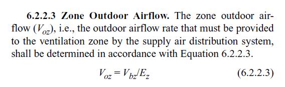
52 52 MAX Discharge ASHRAE 62.1

53 Logic is the beginning, not the end, of Wisdom. - Spock Room Temp Cooling Setpoint PID 0-100% Temp Demand Signal Damper Actuator Mr. Scott we need more power! Room Temp Heating Setpoint PID 0-50% Temp Demand Signal Heating Valve Damper Actuator 53
54 Grouping AHU Zone Group Zones 54
55 Multizone AHU Mixing Box Control The guideline provides some key differences that are important to know about. We will be covering mixing box control and supply air control There are other new control strategies that the guideline implements for multizone AHU s that we will not be covering today.
56 56 Mulitzone AHUs
57 57 Mulitzone AHUs

58 Deviation from Status Quo Individual Analog Outputs for each actuator on the economizer dampers! 58
59 Status Quo Mixing Box Control AHU SAT AHU SAT Set Point PID 0-100% Temp Demand Signal 25% Demand EAD 25% Open RAD 75% Open OAD 25% Open
60 Damper Position % Open Mixing Box Control Traditional 100 % RAD OAD EAD OA Minimum 0% 0% Supply Air Control Loop signal 100 %
61 GL36 Mixing Box Control AHU SAT AHU SAT Set Point PID 0-100% Temp Demand Signal 25% Demand EAD 100% Open RAD 100% Open OAD 25% Open
62 62 New Mixing Box Control
63 63 Mixing Box Control with AFMS
64 RP-1455 Supporting Data Source: 4/19/2016 Seminar at PEC 64
65 Example S.Q. Mixing box PID 0-100% 0% Temp Demand Signal 20% Open Return Fan EA 80% Open CC-1 Supply Fan OA 20% Open 65
66 Example S.Q. Mixing box PID 0-100% 60% Temp Demand Signal 60% Open Return Fan EA OA 40% Open 60% Open CC-1 Supply Fan Call for Cooling Drop in SAT 66

67 Example GL36 Mixing box PID 0-100% 60% Temp Demand Signal 100% Open Return Fan EA OA 80% Open 100% Open CC-1 Supply Fan Call for Cooling Drop in SAT 67
68 68 GL36 Building Pressure Control
69 69 No Building pressure Control?
70 Guideline 36 vs Status Quo Mixing Box Control Status Quo Dependent Damper Control
71 Guideline 36 vs Status Quo Mixing Box Control Status Quo Dependent Damper Control
72 Guideline 36 vs Status Quo Mixing Box Control Status Quo Dependent Damper Control
73 Guideline 36 vs Status Quo Mixing Box Control Status Quo Dependent Damper Control
74 Multizone AHU Supply Air Control How is GL 36 Different? We just saw changes in mixing box control The GL uses space demand to inform the AHU supply air temp. Not OAT. Space demand is weighted to better reflect the demand's potential impact on the system.
75 OAT Guideline 36 vs Status Quo SAT Control Status Quo OAT Reset (Maybe) 70 F 35 F 55 F 75 F Air Handler Discharge Air Set Point

76 Guideline 36 vs Status Quo SAT Control Status Quo OAT Reset (Maybe)


77 Guideline 36 vs Status Quo


78 Guideline 36 vs Status Quo SAT Control Status Quo


79 Guideline 36 vs Status Quo SAT Control GL 36
80 Open vs Closed Loop Control This is a key concept to bringing modern day control to life Being able to identify open / closed loop control is essential to understanding why they implemented some of these sequences Lets talk about it in terms of Supply air temperature reset
81 Status Quo Open Loop SAT Reset OAT AHU SAT SPACE TEMP
82 Open Loop No Feedback OAT AHU SAT SPACE TEMP TRYING TO CONTROL THIS
83 Open Loop No Feedback OAT AHU SAT SPACE TEMP BY RELYING ON THIS INPUT TRYING TO CONTROL THIS
84 Open Loop No Feedback OAT AHU SAT SPACE TEMP THE LOOP IS OPEN (BROKEN) BY RELYING ON THIS INPUT TRYING TO CONTROL THIS

85 Open Loop at Home Clothes Dryer is Open Loop Heat Setting plus Timer = Hopefully Dry

86 Closed Loop at Home Refrigerator is Closed Loop Too Warm Inside, Turn on the Compressor
87 Status Quo Open Loop SAT Reset OAT Determines SAT OAT AHU SAT SPACE TEMP
88 How to Close the Loop OAT AHU SAT SPACE TEMP
89 Guideline 36 Closed Loop SAT Reset SAT Control GL 36 Heating / Cooling Requests Closed Loop AHU SAT SPACE TEMP
90 Importance Multiplier SAT Control GL 36 Heating / Cooling Requests Closed Loop SPACE DMD SPACE DMD AHU SAT SPACE DMD SPACE DMD
91 Importance Multiplier SAT Control GL 36 Weighted Heating / Cooling Requests Closed Loop SPACE DMD! X AHU SAT SPACE DMD SPACE DMD! X! X SPACE DMD! X Importance Multiplier
92 Importance Multiplier SAT Control GL 36 Weighted Heating / Cooling Requests Closed Loop SPACE DMD! X AHU SAT SPACE DMD SPACE DMD! X! X SPACE DMD! X Importance Multiplier
93 Guideline 36 vs Status Quo SAT Control GL 36 Weighted Heating / Cooling Requests Closed Loop SPACE DMD! X AHU SAT SPACE DMD SPACE DMD! X! X SPACE DMD! X Importance Multiplier
94 Guideline 36 vs Status Quo SAT Control Status Quo 1) Supply air temperature will be reset proportionally based on the outside air temperature per the following schedule: OAT SAT
95 Guideline 36 vs Status Quo SAT Control GL 36 Importance Multiplier Example 1) Supply air temperature will be reset using a weighted heating and cooling request and response. A PID will handle the response portion to the summed heating and cooling requests where: 1) Heating and cooling requests cancel each other out. 2) The heating/cooling request value is calculated as the difference between room and overage of the current heating or cooling set point as seen in Figure 3 - Heating Cooling Request Graph (Zone level Logic). A pseudo logical block diagram of this can be found in ATC ) The request value is multiplied by the design CFM of the box. This multiplication is called an importance multiplier and will be referenced in other sequences. 4) The result of the multiplied value is then summed with all the other requests from all the other s. 5) The result of that summation is then divided by the discharge total CFM provided by the AHU. 6) The result of the division is then used as the input of a PID with a fixed set point of zero. This result may be multiplied by 10 or 100 if required by the specific PID being used. The PID shall be configured in such a way that the loop will output 50% when its input is equal to set point (or PID Bias will equal 50%). 7) The result of the PID is then used as the input of a linear reset. This reset shall use the PIDs output range (0-100) to reset the supply air temperature set point between SAT-min and SAT-max. 8) The calculated supply air temperature set point shall be able to be overridden at the user interface.
96 Importance Multiplier in Action SPACE DMD! X SPACE DMD SPACE DMD! X! X SPACE DMD! X Importance Multiplier
97 Importance Multiplier in Action Space Demand Importance Multiplier
98 Importance Multiplier in Action Space Demand Importance Multiplier Demand Sent to AHU
99 Importance Multiplier in Action One Step Further Include CFM Space Demand Importance Multiplier Space Design CFM
100 Importance Multiplier in Action One Step Further Include CFM Space Design CFM Space Demand Importance Multiplier
101 Importance Multiplier in Action One Step Further Include CFM Space Design CFM Space Demand Importance Multiplier Demand Sent to AHU
102 Importance Multiplier Quick Review GL 36 uses an integer importance multiplier. Requires user / designer input Allows for future modification Can default to 1 for all zones at turnover We suggest including the zone design CFM. Implementer has this information readily available Direct reflection of zone s potential demand on AHU
103 First the Zones AHU SAT SPACE TEMP
104 Now the AHU AHU SAT SPACE TEMP
105 Trim and Respond
106 Trim LOWER STATIC SETPOINT FAN SPEED DROPS CFM DROPs WAIT X MINUTES
107 Trim LOWER STATIC SETPOINT FAN SPEED DROPS CFM DROPs Damper Opens
108 Trim Requests more static LOWER STATIC SETPOINT FAN SPEED DROPS CFM DROPs WAIT X MINUTES
109 and Respond Requests more static Requests more static
110 Respond INCREASE STATIC SETPOINT FAN SPEED RAISES CFM INCREASES WAIT X MINUTES

111 Trim and Respond

112 From the Horse s Mouth
113 Guideline 36 vs Status Quo Trim and Respond Lot s O Variables
114 Network Traffic Guideline 36 is a collection of sequences, and doesn t give much guidance in terms of the controls network All these new sequences create more dependency on a fully networked control system Therefore, it s important to discuss the network architecture when talking about implementing the guideline.

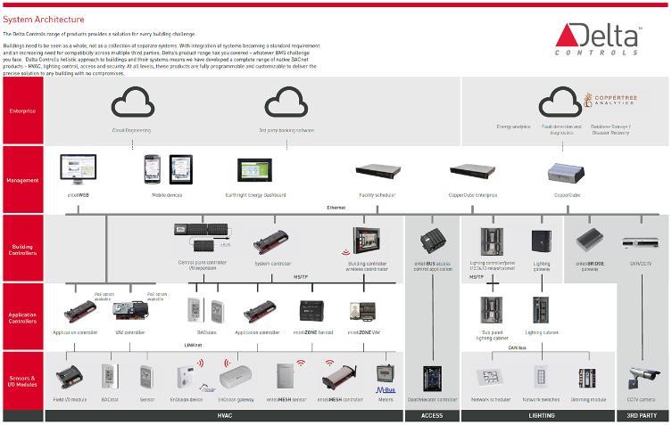
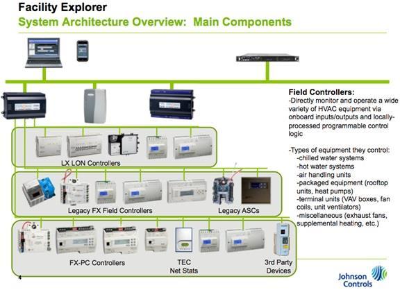
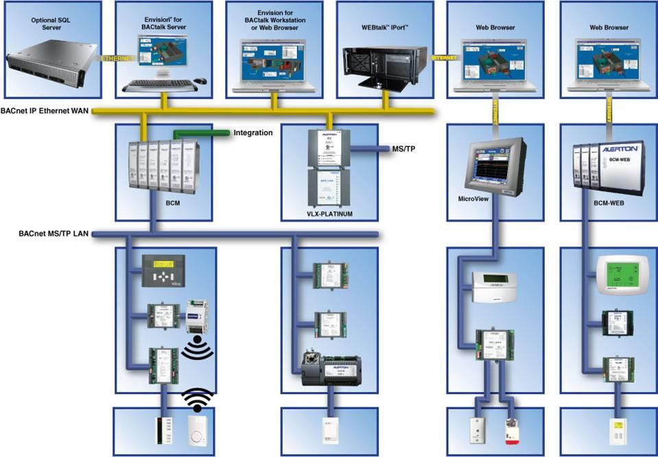
115 Controls Network Architecture 115
116 Controls Network Architecture LAN / Internet / Cloud SERVER PC GLOBAL AHU-1 EXH. FAN AHU-2 116

117 Controls Network Architecture Enterprise / Campus Level Building Level Equipment Level Zone Level SERVER PC GLOBAL AHU-1 AHU-2 EXH. FAN 117


118 Controls Network Architecture Enterprise / Campus Level SERVER PC GLOBAL Has Ethernet Has RS-485 Building Level AHU-1 Has Ethernet, Has Modbus, Attached to meters AHU-2 Equipment Level Zone Level EXH. FAN End Device Sensor Actuator Relay Lights 118

119 119 Controls Network Architecture

120 120 Controls Network Architecture
121 121 Controls Network Architecture
122 122 Controls Network Architecture

123 123 Controls Network Architecture
124 Controls Network Architecture LAN / Internet / Cloud SERVER PC GLOBAL AHU-1 EXH. FAN AHU-2 124
125 Controls Network Architecture LAN / Internet / Cloud SERVER PC AHU-1 GLOBAL EXH. FAN AHU-2 125

126 126 If it ain t broke
127 Why Is this important? LAN / Internet / Cloud SERVER PC GLOBAL AHU-1 EXH. FAN AHU-2 127
128 Why Is this important? LAN / Internet / Cloud SERVER PC GLOBAL AHU-1 EXH. FAN AHU-2 128

129 Why Is this important? LAN / Internet / Cloud SERVER PC GLOBAL AHU-1 EXH. FAN AHU-2 129
130 Controls Network Architecture LAN / Internet / Cloud SERVER PC AHU-1 GLOBAL EXH. FAN AHU-2 130
131 Controls Network Architecture LAN / Internet / Cloud SERVER PC AHU-1 GLOBAL EXH. FAN AHU-2 131

132 132 You can no longer not know that
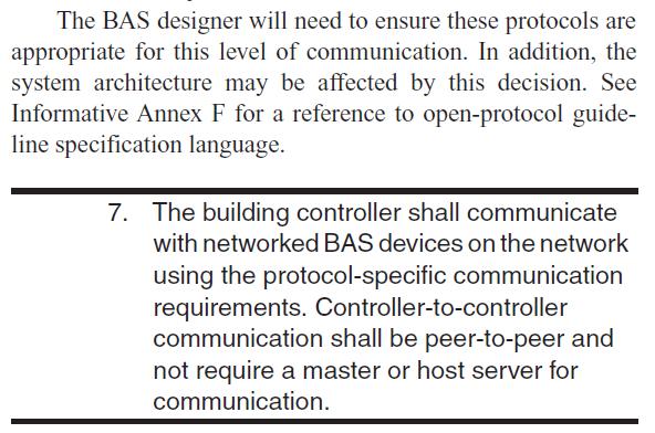
133 Network Architecture Quick Review GL 36 sequences require more network traffic that usual ASHRAE GL 13 architecture limits failure impact Easy to implement, requires planning Collaborate with your implementer (this may be new to them). Yes Traffic is increased, however, not beyond the capacity of a modern day control system using a industry standard open communications protocol.

134 Efficient Alarming
135 Traditional Alarming Alarming Status Quo Alarm Everything AHU Chiller Pump AHU
136 Traditional Alarming Alarming Status Quo Alarm Everything AHU Chiller Pump AHU
137 Traditional Alarming Alarming Status Quo Alarm Everything AHU Chiller Pump AHU
138 Traditional Alarming Alarming Status Quo Alarm Everything AHU Chiller Pump AHU
139 Traditional Alarming Alarming Status Quo Alarm Everything AHU Chiller Pump AHU
140 Traditional Alarming Alarming Status Quo Alarm Everything AHU Chiller Pump AHU

141 How do we Prevent the Unnecessary Alarms?

142 Use a Hierarchy Alarming GL 36 Hierarchical Alarming There s always a bigger fish


143 Use a Hierarchy Alarming GL 36 Hierarchical Alarming Source Load
144 Remember This? AHU Chiller Pump AHU
145 Source Alarms Suppress Load Alarms Alarming GL 36 Hierarchical Alarming AHU Chiller Pump AHU
146 Source Alarms Suppress Load Alarms Alarming GL 36 Hierarchical Alarming AHU Chiller Pump AHU
147 Source Alarms Suppress Load Alarms Alarming GL 36 Hierarchical Alarming AHU Chiller Pump AHU
148 Source Alarms Suppress Load Alarms Alarming GL 36 Hierarchical Alarming AHU Chiller Pump AHU
149 Smart Alarming Quick Review Guideline 36 provides a source / load alarm relationship Creates significantly fewer alarms in the system Makes the system more time efficient from a troubleshooting perspective Aims at using a bit more logic to inhibit alarms intelligently No more boy cried wolf alarm logs
150 Fault Detection and Diagnostics

151 Fault Detection and Diagnostics
152 Fault Detection and Diagnostics Fault Detection and Diagnostics Defined in GL 36 as: Assessing equipment performance
153 Fault Detection and Diagnostics Fault Detection and Diagnostics Defined in GL 36 as: Assessing equipment performance By comparing BAS inputs and outputs
154 Fault Detection and Diagnostics Fault Detection and Diagnostics Defined in GL 36 as: Assessing equipment performance By comparing BAS inputs and outputs To potential fault conditions

155 Fault Detection and Diagnostics Fault Detection and Diagnostics Defined in GL 36 as: Assessing equipment performance By comparing BAS inputs and outputs To potential fault conditions

156 Fault Detection and Diagnostics Fault Detection and Diagnostics A Binary Comparison PASS / FAIL
157 FDD Implementation Equipment Operating State (OS) Operating State Heating Valve Position Cooling Valve Position Outdoor Air Damper Position #1: Heating >0 =0 =MIN #2: Economizer Cooling, Modulating OA =0 =0 Min < X <100% #3: Mechanical + Economizer Cooling =0 >0 =100% #4: Mechanical Cooling + Min OA =0 >0 =MIN #5: Unknown or Dehumidification No other OS applies
158 FDD Implementation Variable Definition Variable Name Description Default Value ΔT SF Temperature rise across supply fan 2 F ΔT MIN Minimum difference between OAT and RAT to evaluate economizer error 5 F conditions θ SAT Temperature error threshold for SAT sensor 2 F θ RAT Temperature error threshold for RAT sensor 2 F θ MAT Temperature error threshold for MAT sensor 2 F θ OAT Temperature error threshold for OAT sensor 2 F θ F Airflow Error threshold 3% θ VFD SPD VFD Speed Error threshold 5% θ DSP Duct static pressure error threshold 0.2" ΔOS Max Mode Delay Maximum number of changes in Operating State Time in minutes to suspend fault condition evaluation after a change in operating state Alarm Delay Time in minutes that a fault condition must persist before triggering an alarm 60
")
159 FDD Implementation - AHU Example Supply Air Temperature Fault (operating state)
160 FDD Implementation - AHU Example Mixed Air Temperature Fault Equation MAT AVG - θ MAT > MAX [(RAT AVG - θ RAT ), (OAT AVG - θ OAT )] FC #3 Description MAT too high; should be between OAT and RAT RAT sensor error Possible MAT sensor error Diagnosis OAT sensor error Applies to: OS #1- #5
161 FDD Implementation - AHU Example Mixed Air Temperature Fault MAT AVG - θ MAT > MAX [(RAT AVG - θ RAT ), (OAT AVG - θ OAT )] Variable Name Example Value RAT AVG 68 F MAT AVG 52 F OAT AVG 28 F θ RAT 2 F θ MAT 1 F θ OAT 2 F
162 FDD Implementation - AHU Example Mixed Air Temperature Fault MAT AVG - θ MAT > MAX [(RAT AVG - θ RAT ), (OAT AVG - θ OAT )] Variable Name Example Value RAT AVG 68 F MAT AVG 52 F OAT AVG 28 F (52-1) > MAX [(68 2), (28-2)] θ RAT 2 F θ MAT 1 F θ OAT 2 F
163 FDD Implementation - AHU Example Mixed Air Temperature Fault MAT AVG - θ MAT > MAX [(RAT AVG - θ RAT ), (OAT AVG - θ OAT )] Variable Name Example Value RAT AVG 68 F MAT AVG 52 F OAT AVG 28 F θ RAT 2 F θ MAT 1 F θ OAT 2 F (52-1) > MAX[(68 2), (28-2)] Is (51) > (66)? No, No Fault
164 FDD Implementation - AHU Example Mixed Air Temperature Fault MAT AVG - θ MAT > MAX [(RAT AVG - θ RAT ), (OAT AVG - θ OAT )] Variable Name Example Value RAT AVG 68 F MAT AVG 71 F OAT AVG 28 F θ RAT 2 F θ MAT 1 F θ OAT 2 F (71-1) > MAX[(68 2), (28-2)] Is (70) > (66)? YES, Fault (But no Alarm!)
165 FDD Implementation Using the Inputs Average Temperatures From the GL (and in your specs) The following values must be continuously calculated by the FDD routines for each AHU: There is a LONG list. This is just a small portion of it.
166 FDD Implementation Using the Inputs Average Temperatures From the GL (and in your specs) The following values must be continuously calculated by the FDD routines for each AHU: Five minute (default) rolling averages, one minute samples of the followings point values; operator shall have the ability to adjust the averaging window and sampling rate for each point independently SAT AVG = rolling average of supply air temperature MAT AVG = rolling average of mixed air temperature RAT AVG = rolling average of return air temperature OAT AVG = rolling average of outdoor air temperature DSP AVG = rolling average of duct static pressure

167 In conclusion
168 168 Questions?
169 Thank You for attending! Rick Stehmeyer - Senior Engineer Matt Napolitan - Principal
HVAC Controls Upgrades: Requirement Details ( )
") REQUIRED CONTROLS/FEATURES To qualify the upgrade must add or substantially modify 3 or more sequences/system capabilities. Also, all sequences and items listed under the required section are needed in
REQUIRED CONTROLS/FEATURES To qualify the upgrade must add or substantially modify 3 or more sequences/system capabilities. Also, all sequences and items listed under the required section are needed in
AIR HANDLING SYSTEM RETRO-COMMISSIONING TRENDING ANALYSIS
 AIR HANDLING SYSTEM RETRO-COMMISSIONING TRENDING ANALYSIS 1 AIR HANDLING UNIT TRENDS 2 1. The trending charts provided on the following pages prepared as part of a retro-commissioning investigation. The
HVAC Controls Upgrades: Requirement Details ( )
") REQUIRED CONTROLS/FEATURES HVAC non CENTRAL PLANT 1) Zone Level Scheduling & Override for all air handlers (supply and exhaust) to match occupied hours by zone DDC or occupancy sensors (OS) allowed. (403.2.4.3,
REQUIRED CONTROLS/FEATURES HVAC non CENTRAL PLANT 1) Zone Level Scheduling & Override for all air handlers (supply and exhaust) to match occupied hours by zone DDC or occupancy sensors (OS) allowed. (403.2.4.3,
SECTION SEQUENCE OF OPERATIONS FOR HVAC CONTROLS
 PART 1 - GENERAL SECTION 23 09 93 SEQUENCE OF OPERATIONS FOR HVAC CONTROLS 1.1 SUMMARY A. This Section includes control sequences for HVAC systems, subsystems, and other equipment. B. See Division 23 Section
10+ HVAC Troubleshooting Tips for Healthcare Facilities Jerry Hirsch JCI Facility O&M Performance Development Manager.
 10+ HVAC Troubleshooting Tips for Healthcare Facilities Jerry Hirsch JCI Facility O&M Performance Development Manager 2019 WHEA Webinar Johnson Controls Institute Overview Operation & Maintenance (O&M)
Verasys System Operation Overview Technical Bulletin
 Contents subject to change. Verasys System Operation Overview Technical Bulletin Code No. LIT-12012370 Issued January 2016 Refer to the QuickLIT Web site for the most up-to-date version of this document.
Digital Precise Air Control - DPAC
 Digital Precise Air Control - DPAC Mode Enable Sensor Options The temperature of this sensor will determine if the unit is in heating, cooling or vent mode during Occupied operation. The following options
Continuous Commissioning: A Valuable Partner to Retrofit Projects
 Continuous Commissioning: A Valuable Partner to Retrofit Projects Yeqiao Zhu Aamer Athar Kenneth Banks Ph.D. PE, CEM PE, CEM Energy Systems Laboratory Sempra Energy Solutions Sempra Energy Solutions Charles
Your Home. Jacco & Assoc.
 Your Home Fan on with call for heating or cooling Heating on with call from space thermostat Stage as required to maintain The 75F Basics adj. - First stage of heating shall be heat pump Cooling on with
SECTION SEQUENCE OF OPERATIONS FOR HVAC CONTROLS
 SECTION 23 09 93 SEQUENCE OF OPERATIONS FOR HVAC CONTROLS PART 1 - GENERAL 1.1 SUMMARY A. This Section includes control sequences for HVAC systems, subsystems, and equipment. B. See Division 23 Section
Manual Supplement. Product/System Title: Static Pressure Controller. Contents of this manual supplement include:
 Model Number: Product/System Title: 8635-ST Static Pressure Controller Contents of this manual supplement include: 1) Sequence of operation 2) Description of new software items 3) Deleted software menu
Improving Performance with a Building Tune-Up. Janice Peterson, P.E. LEED AP Market Manager, Building Operations BetterBricks
 Improving Performance with a Building Tune-Up Janice Peterson, P.E. LEED AP Market Manager, Building Operations BetterBricks How much is too much? Most buildings can cut total energy use by 5-30% while
SEQUENCE OF OPERATION FOR ALC CONTROL AIR SOURCE HEATPUMP RECIRCULATION AIR WITH ECONOMIZER
 SEQUENCE OF OPERATION FOR ALC CONTROL AIR SOURCE HEATPUMP RECIRCULATION AIR WITH ECONOMIZER Printed in the USA ADSOOASHPRAE 0117 Orig SEQUENCE OF OPERATION The ALC controller is turned on by a switch located
SEQUENCE OF OPERATION FOR ALC CONTROL AIR SOURCE HEATPUMP 100% OUTSIDE AIR
 SEQUENCE OF OPERATION FOR ALC CONTROL AIR SOURCE HEATPUMP 100% OUTSIDE AIR Printed in the USA ADSOOASHPOA 0117 Orig SEQUENCE OF OPERATION The ALC controller is turned on by a switch located on its front
INTRODUCTION TO: ASHRAE STANDARD 90.1, HVAC System Requirements for Reducing Energy Consumption in Commercial Buildings
 INTRODUCTION TO: ASHRAE STANDARD 90.1, 2013 HVAC System Requirements for Reducing Energy Consumption in Commercial Buildings Rocky Mountain ASHRAE Technical Conference, April 29, 2016 SEAN BEILMAN, P.E.,
TEC Controller Terminal Box Controller (VAV) - Series Fan Powered with Hot Water Reheat, Application Application Note
 - Series Fan Powered with Hot Water Reheat, Application Application Note") TEC Controller Terminal Box Controller (VAV) - Series Fan Powered with Hot Water Reheat, Application 2025 Application Note 140-1054 Building Technologies Table of Contents Overview... 4 Hardware Inputs...
TEC Controller Terminal Box Controller (VAV) - Series Fan Powered with Hot Water Reheat, Application 2025 Application Note 140-1054 Building Technologies Table of Contents Overview... 4 Hardware Inputs...
York 25-Ton VAV Rooftop Unit
 HVAC PRO for Windows User s Manual 637.5 OEM Section Technical Bulletin Issue Date 0996 York 25-Ton VAV Rooftop Unit Introduction Page 3 Overview *3 Configuration 5 Sequence of Operation 7 Modes of Operation
TEC Controller Terminal Box Controller (VAV) - with Hot Water Reheat, Application Application Note Building Technologies
 - with Hot Water Reheat, Application Application Note Building Technologies") TEC Controller Terminal Box Controller (VAV) - with Hot Water Reheat, Application 2023 Application Note 140-1052 Building Technologies Table of Contents Overview... 4 Hardware Inputs... 6 Hardware Outputs...
TEC Controller Terminal Box Controller (VAV) - with Hot Water Reheat, Application 2023 Application Note 140-1052 Building Technologies Table of Contents Overview... 4 Hardware Inputs... 6 Hardware Outputs...
Model 8682-KET Sequenced Offset (Flow Tracking) and Static Pressure Controller with Dual Exhaust Modulation for Temperature Control
 and Static Pressure Controller with Dual Exhaust Modulation for Temperature Control") Critical Environments Model 8682KET Sequenced Offset (Flow Tracking) and Static Pressure Controller with Dual Exhaust Modulation for Temperature Control Manual Supplement Contents of this manual supplement
Critical Environments Model 8682KET Sequenced Offset (Flow Tracking) and Static Pressure Controller with Dual Exhaust Modulation for Temperature Control Manual Supplement Contents of this manual supplement
UNT Applications. Using UNT Applications...3. Introduction Key Concepts UNT Controller Applications Fan Coil Units...
 Application Note Issue Date 04/17/08 Supersedes 01/11/01 APPLICATION NOTE Using...3 Introduction... 3 Key Concepts... 4 UNT Controller Applications... 4 Fan Coil Units... 8 Unit Ventilators... 11 Rooftop
MicroTech Self-Contained Air Conditioning System
 Open Protocol Data Information Packet Version 2.3 Group: Controls Date: October 1999 MicroTech Self-Contained Air Conditioning System Open Protocol Data Communications t 2002 McQuay International - C O
ADDISON SEQUENCE OF OPERATION FOR ALC CONTROL AIRSOURCE COOLING-ONLY 100% OUTSIDE AIR VERSION Telephone:
 ADDISON SEQUENCE OF OPERATION FOR ALC CONTROL AIRSOURCE COOLING-ONLY 100% OUTSIDE AIR VERSION 2.0 www.addison-hvac.com Telephone: +1.407.292.4400 1 SEQUENCE OF OPERATION The ALC controller is turned on
SECTION SEQUENCE OF OPERATION FOR HVAC CONTROLS PART 1 GENERAL
 SECTION 15910 SEQUENCE OF OPERATION FOR HVAC CONTROLS PART 1 GENERAL 1.1 RELATED DOCUMENTS A. Drawings and general provisions of the Contract, including General and Supplementary Conditions and other Division
ADDISON SEQUENCE OF OPERATION FOR ALC CONTROL AIRSOURCE HEATPUMP 100% OUTDOOR AIR VERSION Telephone:
 ADDISON SEQUENCE OF OPERATION FOR ALC CONTROL AIRSOURCE HEATPUMP 100% OUTDOOR AIR VERSION 2.0 www.addison-hvac.com Telephone: +1.407.292.4400 1 2 OCCUPIED MODE: When the program control source calls for
Sequence of operation
 Sequence of operation IPS 4000 secondary variable speed control File No: 90.96 Date: february 21, 2013 Supersedes: new Date: new sequence of operation ips 4000 2 list of abbreviations: adj: Field Adjustable
TEC Controller VAV 0-10V Fan Control with Hot Water Heat, Application Application Note Building Technologies
 TEC Controller VAV 0-10V Fan Control with Hot Water Heat, Application 2236 Application Note 140-1228 Building Technologies Table of Contents Overview... 4 Hardware Inputs... 10 Hardware Outputs... 10
RPM1600 Series Room Pressure Monitors
 RPM1600 Series Room Pressure Monitors Technical Bulletin LB-RPM1611-0, LB--0 Code No. LIT-12012228 Issued October 2017 Refer to the QuickLIT website for the most up-to-date version of this document. How
ASHRAE Guideline 36P: High Performance Sequences of Operation for HVAC Systems
 ASHRAE Guideline 36P: Hih Performance Sequences of Operation for HVAC Systems Jim Cooan, PE Siemens Buildin Technoloies ASHRAE Distinuished Lecture Proram February 2018, Wisconsin Chapter Pae 1 Aenda ASHRAE
Reciprocating Chiller
 HVAC PRO for Windows User s Manual 637.5 OEM Section Technical Bulletin Issue Date 1094 Reciprocating Chiller Reciprocating Chiller Page 3 Description 3 Theory of Operation 5 Overview 5 Control Sequence
1.0 Digital Controller
 1.0 Digital Controller...1 1.1 Display Function Keys...1 1.2 Thermostat Display...2 1.3 Controller hardware input output points... 4 2.0 Sequence of Operation...5 2.1 States of Operation...5 2.2 Modes
Modeling projects that require very tight space temperature control
 Modeling projects that require very tight space temperature control Whereas space temperature controls for maintaining human thermal comfort typically have a deadband of several degrees between heating
Rooftop Unit, Heat Pump and Indoor Air Quality Application Guide. SE8600 Series Room Controllers
 Rooftop Unit, Heat Pump and Indoor Air Quality Application Guide SE8600 Series Room Controllers 2 TABLE OF CONTENTS Overview 2 SE8600 Rooftop Unit and Indoor Air Quality Controllers 3 SE8600UxBxx 2 Heating
1.0 Digital Controller
 Form CP-AHU D19_D21_D22 (11-17) D303072-A Obsoletes Forms CP-Preeva-D21 (1-16) Doc No 303072, CP-Preeva-D19 (1-16) Doc No 303071 Applies to: Preeva, MAPS, MAPS II, RPB, RPBL & SSCBL Series For Air Handler
A. Base Bid: 1. Heating Contractor provide: a. Control sequences for HVAC systems, subsystems, and equipment.
 SECTION 23 09 93 - SEQUENCE OF OPERATIONS FOR HVAC CONTROLS PART 1 - GENERAL 1 WORK INCLUDES A. Base Bid: Heating Contractor provide: Control sequences for HVAC systems, subsystems, and equipment. B. Alternate
Multi-Story Building Smoke Control with FSCS Override - Metasys System Extended Architecture
 Multi-Story Building Smoke Control with FSCS Override - Metasys System Extended Architecture Code No. LIT-1201737 Release 1.2 Issued January 10, 2005 Document Introduction.................................................
Table of Contents. W2W Open
 W2W Open Points and Properties CARRIER CORPORATION 2013 A member of the United Technologies Corporation family Stock symbol UTX Catalog No. 11-808-457-01 3/27/2013 Table of Contents Introduction... 1
GeneSys Air-Cooled Screw Compressor Chiller
 Operation Manual OM AGSB-5 Group: Chiller Part Number: 331373201 Date: June 2005 Supersedes: OM AGSB-4 GeneSys Air-Cooled Screw Compressor Chiller AGS 230A/B through AGS 475A/B, 60 Hertz AGS 206A/B through
DACC Health Sciences Building Air Handler Assessment/Study
 DACC Health Sciences Building Air Handler Assessment/Study NMSU Facilities and Services Department P.O. Box 30001 Las Cruces, NM 88003-8001 June 14, 2016 Final Submittal 1065 S. Main St., Bldg. D, Ste.
 ZIP Economizer Method of Operation Sequence of Operation States Virgin State The ZIP Economizer comes shipped from the factory in this state. Setup Incomplete will be displayed. No control will occur until
American University Design Standards
 25 95 00 CONTROL SEQUENCES FOR HVAC PART 1. GENERAL 1.01 SECTION INCLUDES A. Description of Work B. Control Sequences General Requirements C. System Specific Control Sequences 1.02 RELATED DOCUMENTS A.
Manual Supplement. Model Number: 8680-N2. Communications Protocol. Contents of this manual supplement include:
 Model Number: 8680-N2 Product/System Title: Room Pressure AOC Controller with N2 Communications Protocol Contents of this manual supplement include: 1) Sequence of Operation 2) Variable map 3) Description
Matt Cooper, PE, BEMP, HBDP, Group 14 Engineering Ken Urbanek, PE, HBDP MKK Consulting Engineers, Inc.
 M&V Real Results of High Performance Design Matt Cooper, PE, BEMP, HBDP, Group 14 Engineering Ken Urbanek, PE, HBDP MKK Consulting Engineers, Inc. Overview Measurement & Verification (M&V) Plan for New
DX-9100 Applications from Engineering Services
 System 9100 Technical Manual 636.4 Application Examples Section Technical Bulletin Issue Date 0896 DX-9100 Applications from Engineering Services Introduction Page 3 Overview 3 Air Handling Unit Applications
Rooftop Unit, Heat Pump and Indoor Air Quality Application Guide VT8600 Series Room Controllers
 Rooftop Unit, Heat Pump and Indoor Air Quality Application Guide VT8600 Series Room Controllers TABLE OF CONTENTS Overview 2 VT86X0U5X00B 2 heating / 2 Cooling for Rooftop unit and Indoor air quality 3
MicroTech Unit Ventilator
 Open Protocol Data Information Packet Version 2.2 Group: Controls Date: April 1996 MicroTech Unit Ventilator Open Protocol Data Communications 2002 McQuay International - C O N F I D E N T I A L - This
BACnet PTEC Controller VAV 0 to 10V Series Fan and 3- Stage Electric Heat, Application 6657
 BACnet PTEC Controller VAV 0 to 10V Series Fan and 3- Stage Electric Heat, Application 6657 140-1158 Building Technologies Table of Contents Overview... 5 BACnet 14 Hardware Inputs... 14 Room Unit Identification...
Reference Guide for Microprocessor Controller
 Document 483586 Microprocessor Controller for Dedicated Outdoor Air System Reference Guide for Microprocessor Controller Please read and save these instructions for future reference. Read carefully before
DIGI-VAV APPLICATIONS
 DIGI-VAV DIGI-VAV APPLICATIONS Digi-VAV: An optimization kit for Variable Air Volume Air Handling Units (VAV AHU) that ensures individual zone indoor air quality (IAQ), and minimizes system energy consumption.
TEC Controller Unit Conditioner - Two-Pipe Fan Coil Cooling or Heating, Application Application Note Building Technologies
 TEC Controller Unit Conditioner - Two-Pipe Fan Coil Cooling or Heating, Application 2050 Application Note 140-1136 Building Technologies Table of Contents Overview... 4 Hardware Inputs... 5 Hardware Outputs...
BOOK 1 OVERVIEW RD2XRT INSTALLATION AND OPERATION MANUAL. Table of Contents ABOUT BOOK 1:
 4510 Helgesen Drive, Madison, WI, 53718 608.221.4499, 800.627.4499, Fax: 608.221.2824 support@renewaire.com www.renewaire.com RD2XRT INSTALLATION AND OPERATION MANUAL BOOK 1 OVERVIEW ABOUT BOOK 1: This
TAP v2.10 Version Date: 6/12/13. Document Microprocessor Controller for Tempered Air Products
 Document 475595 Microprocessor Controller for Tempered Air Products Reference Guide for the Microprocessor Controller Please read and save these instructions. Read carefully before attempting to operate
TEC Controller Multiple Compressor Heat Pump with Reversing Valve & Mixed Air Control, Application Application Note
 TEC Controller Multiple Compressor Heat Pump with Reversing Valve & Mixed Air Control, Application 2273 Application Note 140-1045 Building Technologies Table of Contents Overview... 4 Hardware Inputs...
Multi-Zone Wireless Control Training Systems ( )
") Multi-Zone Wireless Control Training Systems 593306 (3467-00) LabVolt Series Datasheet Festo Didactic en 120 V - 60 Hz 11/2018 Table of Contents General Description 2 Courseware 2 Topic Coverage 3 List
Multi-Zone Wireless Control Training Systems 593306 (3467-00) LabVolt Series Datasheet Festo Didactic en 120 V - 60 Hz 11/2018 Table of Contents General Description 2 Courseware 2 Topic Coverage 3 List
Your Home. Jacco & Assoc. Fan on with call for heating or cooling Heating on with call from space thermostat Stage as
 Your Home Fan on with call for heating or cooling Heating on with call from space thermostat Stage as required Controlling to maintain 75F HVAC adj. Systems First stage of heating shall be heat pump Cooling
Civil Engineering Building
 Continuous Commissioning Report For the Civil Engineering Building Building 492 Submitted to: Utilities Energy Office Physical Plant Department Texas A&M University Prepared by: Energy Systems Laboratory
Rooftop Unit, Heat Pump and Indoor Air Quality Application Guide
 Rooftop Unit, Heat Pump and Indoor Air Quality Application Guide VT8600 Series Room Controllers TABLE OF CONTENTS Overview 2 VT8600 Rooftop Unit Heat Pump and Indoor Air Quality Controllers 3 VT86X0U5X00B
Tri-Stack Smart System
 Tri-Stack Smart System TM Notes & Warnings - The protection provided by this equipment may be impaired if it is not used in the manner specified herein. - Ensure all wiring meets applicable national and
TEC Controller Single Compressor Heat Pump with Reversing Valve Control, Application Application Note Building Technologies
 TEC Controller Single Compressor Heat Pump with Reversing Valve Control, Application 2070 Application Note 140-1040 Building Technologies Table of Contents Overview... 4 Hardware Inputs... 5 Hardware
UNIFIED FACILITIES GUIDE SPECIFICATIONS
 USACE / NAVFAC / AFCEC / NASA UFGS-23 09 93 (November 2015) ----------------------------- Preparing Activity: USACE Superseding UFGS-23 09 23 (May 2011) UNIFIED FACILITIES GUIDE SPECIFICATIONS References
TEC Controller Heating & Cooling Heat Pump with Internal Reversing Valve & Mixed Air Control, Application 2072
 TEC Controller Heating & Cooling Heat Pump with Internal Reversing Valve & Mixed Air Control, Application 2072 Application Note 140-1042 Building Technologies Table of Contents Overview... 4 Hardware
VCM-X Controller Technical Guide
 2 2 www.orioncontrols.com VCM-X Controller Technical Guide VCM-X Controller Code: SS1026 & Y200920 Version 2.0 and up; VCM-X Modular Controller: Tulsa - SS1030; Coil - SS1034 VCM-X WSHP Controller: Tulsa
An HVAC Audit of the Canberra Institute of Technology
 An HVAC Audit of the Canberra Institute of Technology 30 th November 2016 Amnon Holland amnon.holland@esbsconsult.com.au www.esbsconsult.com.au Agenda Overview CIT and various other sites The sites Type
I/O ZONE 560/583 USERS GUIDE
 I/O ZONE 560/583 USERS GUIDE 641-224 641-242 641-237 1 Table of Contents Hot Gas Re-Heat Valve On/Off:... 15 THE ZONE CONTROLLER...4 Modulating Re-Heat Valve:... 16 SPECIFICATIONS...5 CONTROLLER COMPONENTS...6
DACC - NMDA BUILDINGS
 A PROJECT FOR: LAS CRUCES, NEW MEXICO PROJECT LOCATION LOCATION MAP INDEX OF DRAWINGS: CV001 - COVER SHEET M101 - OVERALL CAMPUS STEAM UTILITY PLAN M102 - DACC DAMA 341 PLAN M103 - DACC LRC & CLASSROOM
BOOK 1 OVERVIEW RD2XIN INSTALLATION AND OPERATION MANUAL. Table of Contents ABOUT BOOK 1:
 4510 Helgesen Drive, Madison, WI, 53718 608.221.4499, 800.627.4499, Fax: 608.221.2824 support@renewaire.com www.renewaire.com RD2XIN INSTALLATION AND OPERATION MANUAL BOOK 1 OVERVIEW ABOUT BOOK 1: This
Meridian wiredhart. HART Field Device Specification Goldmine Rd. Monroe, NC USA
 HART Field Device Specification Meridian wiredhart 4320 Goldmine Rd. Monroe, NC 28110 USA HART is a registered trademark of the HART Communication Foundation TABLE OF CONTENTS 1. Introduction...5 1.1 Scope...5
RSES Technical Institute Training Manual 3 72 hours, 72 NATE CEHs, 7.2 CEUs
 Lesson 1 - Basic Heat Pump Theory (Part 1) Describe the basic operation of a heat pump. Explain the function of various heat pump controls. Interpret the wiring diagrams and performance data provided by
FUNCTIONAL DESIGN SPECIFICATION
 Issue Date: Issued To: Revision: FUNCTIONAL DESIGN SPECIFICATION Specification Number: SP-XXXX Company Name Signature Date Issued By: Manutec Ltd. Approved By: Approved By: Approved By: Approved By: Authorised
Project: SEWPCC Ventilation Upgrades. Table of Contents
 Table of Contents 1.0 Overview... 4 1.1 Associated s... 4 1.2 of Work... 4 1.3 PLC Communications... 5 1.4 Groups and Priorities... 5 2.0 Removals... 6 3.0 Wet Well Venitlation Upgrades... 7 3.1 Wet Well
VCM-X Modular E-BUS Controller Technical Guide
 www.orioncontrols.com VCM-X Modular E-BUS Controller Technical Guide VCM-X Modular E-BUS Controller: Tulsa - SS1030; Coil - SS1034 VCM-X WSHP E-BUS Controller: Tulsa - SS1032; Coil - SS1033 Requires Service
TC-9102 Applications
 Application Note January 7, 2004 APPLICATION NOTE TC-9102 Applications Configuring TC-9102 Applications...3 Introduction... 3 Key Concepts... 4 TC-9102 Controller... 4 Control Modes...8 Procedure Overview...
Manual Supplement. Product/System Title: Premium Clean Room Monitor. Contents of this manual supplement include:
 Model Number: Product/System Title: 8630-PM-CRM Premium Clean Room Monitor Contents of this manual supplement include: 1) Sequence of operation 2) Menu structure drawing 3) Description of new software
AHU Air Handling Unit Fundamentals. j.ilangumaran
 AHU Air Handling Unit Fundamentals j.ilangumaran Objectives Review primary components of an AHU Understand the basic progression and advantages of advanced AHU control Understand the basic control sequences
ExactLogic BACnet Communicating Thermostat EXL01625 Sequence Datasheet Fan Coil with Modulatating H/C and PO-PC H/C
 ExactLogic BACnet Communicating Thermostat EXL01625 Sequence Datasheet Fan Coil with Modulatating H/C and PO-PC H/C DataSheet ev 1.10.403/4.02 November 6, 2012 Operating Sequence Standard Occupied During
Introduction. What is the RTU Open controller?
 TU Open v3 CAIE COPOATION 2017 A member of the United Technologies Corporation family Stock symbol UTX Catalog No. 11-808-521-01 8/22/2017 Verify that you have the most current version of this document
Troubleshooting the Indoor AHU as a Standard Product
 Troubleshooting the Indoor AHU as a Standard Product Indoor Unit Circuit Board Indoor Unit Circuit Board Schematic The TECHs Need to Understand the Status and Fault Codes by LED Lights The control board
Reference Guide for Microprocessor Controller
 Document 483232 Microprocessor Controller for Energy Recovery Reference Guide for Microprocessor Controller Please read and save these instructions for future reference. Read carefully before attempting
ASHRAE Region VI CRC Track III: Session 3 Ventilation Energy Recovery. Steven T. Taylor, PE Principal Taylor Engineering
 ASHRAE Region VI CRC Track III: Session 3 Ventilation Energy Recovery Steven T. Taylor, PE Principal Taylor Engineering This program is registered with the AIA/CES for continuing professional education.
ASHRAE Standard 90.1 Energy Requirements Wrap-Around Heat Pipes
 ASHRAE Standard 90.1 Energy Requirements Wrap-Around Heat Pipes In Humid Climates BY DAVID A. JOHN, P.E., MEMBER ASHRAE; DREW ELSBERRY, MEMBER ASHRAE Designing g a building s HVAC system requires designers
FLORIDA A&M UNIVERSITY PERFORMANCE CONTRACT SCOPE OF WORK
 FLORIDA A&M UNIVERSITY PERFORMANCE CONTRACT SCOPE OF WORK ENERGY CONSERVATION MEASURE 1 Partial Steam System Decentralization SIEMENS will Furnish and Install condensing hot water boilers with associated
EarthWise System Seminar
 EarthWise System Seminar Tim Gasper, P.E. Solutions Engineer Brady-Trane Services, Inc. EarthWise Systems? Energy Efficiency Emissions Buildings use 39% of the Primary Energy Consumed in the United States
Feature Summary. I. System
 I. System A. Supports up to 60 VAV HVAC Units 1. Each HVAC Unit Can Support up to 59 VAV Boxes 2. Constant Volume Units Can Be Integrated With VAV Units 3. System Can Support Over 3000 Controllers B. Fill-in
4. OVERVIEW OF MECHANICAL SYSTEM
 4. OVERVIEW OF MECHANICAL SYSTEM The 87,000 SF SLCC is served by six (6) Trane M-Series Climate Changer Air Handing Units (AHUs). Each unit serves a distinct zone within the facility that is unique in
SECTION SEQUENCE OF OPERATIONS FOR BUILDING CONTROLS
 PART 1 GENERAL 1.01 SECTION INCLUDES SECTION 23 0993 SEQUENCE OF OPERATIONS FOR BUILDING CONTROLS A. This section defines the manner and method by which controls function. Requirements for each type of
High Efficiency Heating and Cooling Systems for Community Colleges Kirk Mescher, PE, LEED AP Principal ICCCFO
 High Efficiency Heating and Cooling Systems for Community Colleges Kirk Mescher, PE, LEED AP Principal ICCCFO 2012 1 Learning Objectives for this Session Get acquainted with typical systems used in the
FieldServer Driver - Serial FS McQuay Microtech Open Protocol
 Description FieldServer Driver - Serial FS-8700-80 McQuay Microtech Open Protocol This is an active client protocol. The driver is capable of acting as a master or slave. As a master, the Fieldserver polls
SEQUENCE OF OPERATIONS
 SEQUENCE OF OPERATIONS DDC CONTROLLER: Controller with integral LCD readout for changing set points and monitoring unit operation. Provided with required sensors and programming. Factory programmed, mounted,
FORM EG2 (502) FlexSys Configured Packaged Rooftop Air Conditioning Units
 FlexSys Configured Packaged Rooftop Air Conditioning Units") FORM 100.50-EG2 (502) TM FlexSys Configured Packaged Rooftop Air Conditioning Units TABLE OF CONTENTS PAGE TOTAL INTEGRATED HVAC SYSTEM... 3 AN INTEGRATED SOLUTION... 4 INTRODUCTION... 6 System Description...
FORM 100.50-EG2 (502) TM FlexSys Configured Packaged Rooftop Air Conditioning Units TABLE OF CONTENTS PAGE TOTAL INTEGRATED HVAC SYSTEM... 3 AN INTEGRATED SOLUTION... 4 INTRODUCTION... 6 System Description...
SEQUENCE OF OPERATION GUIDELINE. AIR TERMINAL UNITS SINGLE DUCT VARIABLE AIR VOLUME with HOT WATER REHEAT or ELECTRIC HEAT
 SEQUENCE OF OPERATION GUIDELINE AIR TERMINAL UNITS SINGLE DUCT VARIABLE AIR VOLUME with HOT WATER REHEAT or ELECTRIC HEAT Document: VAV-HTG rev1 Revision: 1.0 Rev. Date: July 22, 2011 NOTES: 1. THIS SEQUENCE
Dryer Master DM510 Commissioning Guide
 COMMISSIONING GUIDE Dryer Master DM510 Dryer Moisture Systems Inc. 640 Superior Drive Waterloo, Ontario Phone 519.725.4700 Fax 519.885.4300 USA & Canada Toll Free 1-888-318-0009 E-mail: info@dryermaster.com
MODEL 4200-IR-2 (Up to 2 Sensors) MODEL 4200-IR-4 (Up to 4 Sensors) MODEL 4200-IR-6 (Up to 6 Sensors)
 MODEL 4200-IR-4 (Up to 4 Sensors) MODEL 4200-IR-6 (Up to 6 Sensors)") MODEL 4200-IR-2 (Up to 2 Sensors) MODEL 4200-IR-4 (Up to 4 Sensors) MODEL 4200-IR-6 (Up to 6 Sensors) Refrigerant Monitor User Manual Technical Support Continental North America Toll Free 1-(800) 387-9487
MODEL 4200-IR-2 (Up to 2 Sensors) MODEL 4200-IR-4 (Up to 4 Sensors) MODEL 4200-IR-6 (Up to 6 Sensors) Refrigerant Monitor User Manual Technical Support Continental North America Toll Free 1-(800) 387-9487
HVAC Myths and Realities Trane Engineers Newsletter Live Series
 HVAC Myths and Realities Trane Engineers Newsletter Live Series AGENDA Low delta T is unavoidable 55 F supply air temperature is adequate for today s loads ASHRAE Standard 15 has to be updated before new
Models NFPA 1221-A, NFPA 1221-B Public Safety DAS Annunciator Panel. Revision E 61117
 Models NFPA 1221-A, NFPA 1221-B Public Safety DAS Annunciator Panel Revision E 61117 CAUTION: (Read This First) This panel has been designed to make it nearly bullet proof to mistakes made when wiring
Installation and Operation. Tracer ZN521 Zone Controller CNT-SVX07C-EN
 Installation and Operation Tracer ZN521 Zone Controller CNT-SVX07C-EN Installation and Operation Tracer ZN521 Zone Controller CNT-SVX07C-EN April 2005 CNT-SVX07C-EN Tracer ZN521 Zone Controller Installation
OPERATING MANUAL Enertronic Control System 2
 OPERATING MANUAL Enertronic Control System 2 The integrated control system for Lennox chillers in the Ecologic range Manufacturer: Lennox Benelux B.V. Postbus 1028, 3860 BA NIJKERK Watergoorweg 87, 3861
Controls Lite. Controls Instruction, Operation, and Maintenance. IOM-C Part Number
 Controls Lite Controls Instruction, Operation, and Maintenance Part Number 481331 Page 1 Table of Contents Valent Overview... 5 Controls Lite Strategy... 5 Equipment and Control... 6 Third-Party Control
The M & V Guided Recommissioning Process. Energy & Water Conservation Program. September 2015 MOO
 The M & V Guided Recommissioning Process MOO Energy & Water Conservation Program September 2015 EWC Agenda MOO EWC Overview Our approach Progress Fault Detection Zone & customer feedback Variance reporting
C-series Controllers for air handling systems
 C-series Controllers for air handling systems Corrigo, C-series, is a range of digital controllers for air-handling systems designed to be easy to use and operate, having a large capacity, and a high degree
2009 Washington State Non-Residential Energy Code Scott Rushing, PE, LEED AP - Rushing Company Lisa Rosenow, CSBA, LEED AP NEEC
 2009 Washington State Non-Residential Energy Code Scott Rushing, PE, LEED AP - Rushing Company Lisa Rosenow, CSBA, LEED AP NEEC Mechanical Systems Agenda Changes in NREC Chapter 11 Changes in NREC Chapter
Pioneer Gold Controller Technical Guide
 Pioneer Gold Controller Technical Guide Pioneer Gold Controller Code: Version 1.03 Electric Heat Expansion Module Code: Version 1.0 Used with AAON WSHP WV Series Vertical and WH Series Horizontal This