LTE30EX. LTE Primary Cellular Alarm Communicator INSTALLATION & USER S GUIDE
|
|
|
- Steven Thomas
- 6 years ago
- Views:
Transcription

1 INSTALLATION & USER S GUIDE
2 2017 Uplink Security, LLC. All rights reserved. Uplink is a trademark of Uplink Security, LLC. No part of this publication may be reproduced or used in any form without permission in writing from Uplink. This includes electronic or mechanical means, such as photocopying, recording, or information storage and retrieval systems. The material in this manual is subject to change without notice. Uplink reserves the right to make changes to any software or product to improve reliability, function or design. Uplink is a registered trademark of Uplink Security, LLC. All other trademarks are the property of their respective owners. PRODUCT ID # UP4530LTE LTE PRIMARY CELLULAR ALARM COMMUNICATOR
3 TABLE OF CONTENTS Table of Contents...2 Introduction...4 Key Features Warranty & Limitation of Liability FCC and Regulatory Compliance & Part FCC RF Exposure Information...10 Technical Support...11 Installation A. General Considerations...12 B. DIP Switch Settings...12 C. LEDs D. Locating and Installing the LTE30EX...15 E. Connecting the LTE30EX to the Alarm Panel...17 F. Configuring Input G. Activating the LTE30EX...21 H. Programming and Central Station Reporting...22 I. Default Event/ Messages...23 J. Completing the Installation and Testing...23 Specifications Appendix A: Contact ID, SIA, Modem IIe/IIIa 2 Event Codes Appendix B: LTE30EX Default Event Codes
4 3
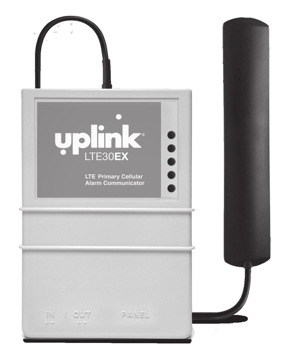
5 INTRODUCTION The Uplink LTE30EX 4G Primary is a LTE alarm communicator designed to be used with almost any manufacturer s alarm panels that incorporate a digital telephone dialer. The Uplink LTE30EX provides a Primary wireless interface to the protected premises and replaces the phone line connection. The Uplink LTE30EX unit will intercept the alarm panel s digital dialer output when the panel has an event to report, and communicate with the panel as if it were a central station alarm receiver. Once the LTE30EX completes a communications session with the alarm panel, it will transmit the alarm information using the local LTE cellular communications network. The Model LTE30EX is compatible with alarm systems and central stations using these formats: Contact ID (SIA-DC05), SIA (SIA-DC03), Modem IIe/IIIa 2 or Pulse 4/2. 4
6 KEY FEATURES A. FULL DATA Reporting. Compatible with most alarm panels using Contact ID (SIA DC-05 Standard), SIA FSK Level 1 (SIA DC-03 Standard), Modem IIe/IIIa 2 or Pulse 4/2 digital dialer formats. All information sent by the alarm panel in these formats (account number, zone information, User IDs, etc.) will be sent to the central station using the LTE network or HSPA 3G network when LTE is not available. B. Power Requirements: Requires constant 12V DC power from a power supply, battery, or alarm panel with a constant 125mA and a peak 600 ma for one second during transmission. C. Panel to LTE30EX Cable Supervision. Monitors continuity of the cable connecting the panel s telephone dialer to the LTE30EX. This feature is activated through the website or by calling Uplink Technical Support: UPLINK ( ) D. Input. The LTE30EX has one programmable input. This input can be programmed to one of the following functions via the website: Standard Input Sampled Siren Pulse Counter Timed Bell E. Output. The LTE30EX has one programmable relay output. This output can be programmed to activate upon the occurrence of one or more of the following trouble conditions: Cellular Network Loss No Central Station Acknowledgement Low DC input Voltage Panel/4530EX Cable Supervision Trouble Unit Disabled by Dealer Command Watchdog Circuit Activation F. Power Source Monitoring (Low DC Input Voltage Reporting). The LTE30EX can report a low input Voltage condition to the central station when its DC input voltage drops below 10.2V DC. It will report Low input Voltage Restoral at 11.4V DC. 5
7 KEY FEATURES (cont.) G. Automated Testing. The LTE30EX can be programmed to send an automated test signal to the central station on a monthly, weekly or daily interval. H. LTE Network Supervision. Supervises the local LTE network. If the unit no longer locates the local LTE Network, its output relay can be set up to report this trouble condition. I. Status/Received Signal Strength LEDs. The five LEDs indicate the current operational status and are visible from outside the enclosure. These LEDs can be placed into Received Signal Strength Indication mode (RSSI) to assist in selecting the optimal mounting location for transmitting and receiving cellular radio signals. J. Easy Initiation. Ships with a SIM card, with easy activations available via the website at or by calling Uplink Customer Service: UPLINK ( ) Requires the central station receiver phone number and/or its IP address and Port number. K. Web-based Services. Available at and include: Secure login for dealers Immediate, real-time activation History of past event transmissions Initiation of a test report The ability to query the unit and receive a real-time radio report status Including a Received Signal Strength reading Programming the output and other internally generated events 6
8 WARRANTY & LIMITATION OF LIABILITY Standard 12-Month Limited Warranty Uplink Security, LLC s limited product warranty extends only to commercial distributors who purchase products directly from Uplink. Uplink s warranty does not extend to end user consumers of Uplink products or to other parties not in privity of contract with Uplink and, to the maximum extend permissible under applicable law, Uplink expressly disclaims any warranty, express or implied, extending to such end user consumer or parties including without limitations, any implied warranties or merchantability and fitness for a particular purpose. End user consumers with questions concerning an Uplink product are directed to contact the alarm/ security system dealer or installer from whom they purchased the product. Distributors, dealers and installers with questions about Uplink s warranty and returns process are directed to contact Uplink Order Entry; issuance of a Return Merchandise Authorization (RMA) number by Uplink is required as a condition prerequisite to the return of any Uplink products under the applicable product warranty. IN NO EVENT SHALL UPLINK OR ANY OF ITS REPRESENTATIVES BE LIABLE TO ANY END USER CONSUMER OF AN UPLINK PRODUCT AND/OR SERVICE OR ANY OTHER PARTY NOT IN PRIVITY OF CONTRACT WITH UPLINK FOR ANY CONSEQUENTIAL, INCIDENTAL, INDIRECT, EXEMPLARY, SPECIAL OR PUNITIVE DAMAGES, INCLUDING ANY DAMAGES FOR BUSINESS INTERRUPTION, LOSS OF USE, DATA, REVENUE OR PROFIT, WHETHER ARISING OUT OF BREAK OF CONTRACT, TORT (INCLUDING NEGLIGENCE OR PRODUCT LIABILITY) OR OTHERWISE, REGARDLESS OF WHETHER SUCH DAMAGES WERE FORESEEABLE AND WHETHER OR NOT UPLINK WAS ADVISED OF THE POSSIBILITY OF SUCH DAMAGES. 7
9 WARRANTY & LIMITATION OF LIABILITY (cont.) IN NO EVENT SHALL UPLINK S AGGREGATE LIABILITY TO ANY END USER CONSUMER OF AN UPLINK PRODUCT AND/OR SERVICE OR OTHER PARTY NOT IN PRIVITY OF CONTRACT WITH UPLINK ARISING OUT OF OR RELATED TO AN UPLINK PRODUCT AND/OR SERVICE, WHETHER ARISING OUT OF OR RELATED TO BREAK OF CONTRACT, TORT (INCLUDING, WITHOUT LIMITATION, NEGLIGENCE OR PRODUCT LIABILITY) OR OTHERWISE, EXCEED THE TOTAL AMOUNT PAID OR PAYABLE TO THE ALARM/SECURITY DEALER OR INSTALLER BY THE END USER CONSUMER FOR SAID PRODUCT AND/OR SERVICE IN THE 12 MONTH PERIOD PRECEDING THE EVENT GIVING RISE TO THE CLAIM OR $250, WHICHEVER AMOUNT IS GREATER. 8
10 FCC & INDUSTRY CANADA REGULATORY COMPLIANCE Part 15 This device complies with Part 15 of the FCC Rules. Operation is subject to the following two conditions: (1) this device may not cause harmful interference, and (2) this device must accept any interference received, including interference that may cause undesired operation. This equipment has been tested and found to comply with the limits for a Class B digital device, pursuant to Part 15 of the FCC Rules. These limits are designed to provide reasonable protection against harmful interference in a residential installation. This equipment generates, uses, and can radiate radio frequency energy and, if not installed and used in accordance with the instructions, may cause harmful interference to radio communications. However, there is no guarantee that interference will not occur in a particular installation. If this equipment does cause harmful interference to radio or television reception, which can be determined by turning the equipment off and on, the user is encouraged to try to correct the interference by one or more of the following measures: Reorient or relocate the receiving antenna. Increase the separation between the equipment and receiver. Connect the equipment into an outlet on a circuit different from that to which the receiver is connected. Consult the dealer or an experienced technician for help. 9
11 FCC RF EXPOSURE INFORMATION In August 1996 the Federal Communications Commission (FCC) of the United States with its action in Report and Order FCC adopted an updated safety standard for human exposure to radio frequency electromagnetic energy emitted by FCC regulated transmitters. Those guide-lines are consistent with the safety standard previously set by both U.S. and international standards bodies. The design of this module complies with the FCC guidelines and these international standards. The FCC ID of this unit is QIPPHS8-US. For more information about RF exposure, please visit the FCC website at The term IC before the certification/registration number only signifies that the Industry Canada Technical Specifications were met. The external antennas used for this module must provide a separation distance of at least 20cm from all persons and must not be co-located or operating in conjunction with any other antenna or transmitter. 10
12 TECHNICAL SUPPORT Technical support is available Monday through Friday, 8:00 AM to 8:00 PM ET excluding holidays. Before calling technical support please ensure you have read the installation guide completely. Technical support requires the caller to provide: Login name Password Serial number of the LTE30EX Uplink Security, LLC. 400 Interstate N Pkwy. Suite 1350 Atlanta, Georgia Uplink ( ) 11
13 INSTALLATION A. General Considerations Determine where to mount the unit. Keep the following in mind: a. Where to obtain the best transmitted and received signal strength for the cellular radio. (If the installer does not have a very strong cellular signal in his area, he may want to first power the unit from a portable 12V DC source, switch on S4 and move the unit to a location that gives him the best signal strength.) b. Proximity to the alarm panel and where to route the LTE30EX relay output that connects to an alarm panel input. B. DIP Switch Settings The LTE30EX has a four-position dipswitch. The dipswitches function as follows: SWITCH NO. SETTING FUNCTION S1: Default Load OFF Normal Operations ON Load Defaults S2: OTA Operation OFF OTA configuration allowed ON OTA configuration blocked S3: Reserved OFF N/A ON N/A S4: LED Function OFF Normal Operations ON RSSI Measurements Allow 30 seconds after moving dip switch for changes to take affect. (INSTALLATION continued next page) 12
14 INSTALLATION (cont.) C. LEDs Normal Mode: Upon initial power up, the 5 LEDs on the LTE30EX will begin to function as follows: LED1 LED2 LED3 LED4 LED5 LED Status - Normal Mode POWER PANEL HOOK STATUS TROUBLE CELLULAR COMM STATUS HEARTBEAT POWER PANEL HOOK STATUS OFF RED NO DC POWER NORMAL DC POWER LOW DC POWER PANEL ON-HOOK PANEL OFF-HOOK TROUBLE RED OUTPUT RELAY NORMAL OUTPUT RELAY OFF-NORMAL CELL COMM STATUS RED RED,, RED WAITING ON ACK UNIT FULLY REGISTERED UNIT NOT REGISTERED UNIT REG. ON DATA ONLY UNIT REG. IN FALLBACK HEARTBEAT RED NORMAL OPERATION S1 ON AFTER RESET rB 13
15 INSTALLATION (cont.) RSSI Mode: When the LTE30EX is placed in Received Signal Strength Indicator (RSSI) Mode by turning Dipswitch S4 to ON, the five LEDs indicate the follow signal strength information: RECEIVED SIGNAL STRENGTH LED1 LED2 BEST LED3 LED4 LED5 LED1 LED2 GOOD LED3 LED4 LED5 LED1 LED2 AVERAGE LED3 LED4 LED5 LED1 LED2 FAIR LED3 LED4 LED5 LED1 LED2 POOR LED3 LED4 LED5 LED1 LED2 Unacceptable LED3 LED4 LED5 OFF FLASH ON No Signal -All LEDs Off RED (INSTALLATION continued next page) 14
16 INSTALLATION (cont.) D. Locating and Installing the LTE30EX The LTE30EX is housed in a plastic enclosure. The installer needs to supply DC power from the panel via the AUX output, or battery, via a separate DC power source. Input DC current is listed on page 25. After carefully considering all of the issues outlined in Installations - General Considerations, page 12, proceed as follows: Separate the top and bottom of the enclosure by depressing the tabs on the sides of the unit and then tilting the bottom of the plastic top outward and up. 2. Connect the antenna that is supplied with the LTE30EX. The Antenna supplied may differ from the ones depicted in the figures in this manual. 3. Go to the red, 4-position Dipswitch as shown in Figure 1 and set the dipswitch as appropriate for this installation. (See DIP Switch Settings, page 12.) 4. Place Dipswitch #4 (S4) in the ON position. The LEDs are now operating in RSSI Mode. Locate a good mounting position based on a good Received Signal Strength Indication (RSSI). It is recommended that the installation location demonstrate an RSSI of at least -80 dbm (two solid green LEDs). The minimum acceptable RSSI is -90 dbm (1 solid green LED). 5. Position the bottom of the LTE30EX enclosure where it will be installed. Use four (4) #6 screws and mount the unit using the four holes in the enclosure s plastic bottom. 6. Make sure that the unit s antenna is connected. 7. Connect the positive (+) and negative (-) terminals of the 12V DC power supply to terminals DC+ and DC - respectively on the LTE30EX. 8. Double check to make sure that the RSSI is still showing a good signal strength level. 9. Before connecting the alarm panel and the LTE30EX, first: a. Return Dipswitch #4 (S4) to the OFF position. b. Disconnect the Positive and Negative connections to the DC power source.
 STATUS LEDS DIP SWITCHES FIGURE 1: Model LTE30EX PC")

17 INSTALLATION (cont.) STATUS LEDS DIP SWITCHES FIGURE 1: Model LTE30EX PC Board Details INPUT OUTPUT RJ 45 DC TERMINAL BLOCK CAUTION: Incorrect Connections May Result in Damage to the Unit (INSTALLATION continued next page) 16
18 INSTALLATION (cont.) E. Connecting the LTE30EX to the Alarm Panel IMPORTANT: Make all of the connections to the LTE30EX in the powered down state. Once all of the connections have been established, turn power on. 1. First, remove DC power from the LTE30EX, and then proceed as follows: 2. Panel Connections Connect the alarm panel s telephone output to the LTE30EX with an appropriate cable. On the LTE30EX s side, the cable should use an RJ45 plug and be connected into Jack JP3. 3. Output The LTE30EX has one relay output that can be used to activate an input on the alarm panel or for other local purposes. Decide on how to use this output (see section 6. Programming) then wire it from the terminal strip to the external panel or device: Output #1 Terminals: OUT1+ and OUT1- The default state for this Output is as follows: OUTPUT DEFAULT STATE DEFAULT DEFINITION #1 Configurable - normally closed Loss of cellular service See Figure 2 as an example of how to connect the LTE30EX to the alarm panel. 17
19 INSTALLATION (cont.) MODEL LTE30EX PRIMARY ALARM COMMUNICATOR CAUTION: Improper Installation at Power Inputs May Damage Unit. 12VDC Operation Only. DO NOT Connect to a Receptacle Controlled by a Switch. See User s Guide and Quick Install Guide for More Details. This system shall be installed in accordance with NFPA Standard 72, Chapter 2. This system must be checked by a qualified technician at least once every three (3) years. Test unit weekly to ensure proper operation. Intended for Dry, Indoor Use only. ALARM PANEL Pin1 Pin4 Pin5 Pin8 Pin2 Pin7 Pin3 Pin6 Switch# Off S1 On S2 S3 S4 Off On Off On Off On Function Normal Operations Load Defaults Allow OTA Config Block OTA Config Normal Operations Reserved Normal Operations RSSI Measurements T1 T R R1 TO RJ31X Panel State Detection (See manual) ZNA+ ZNA- DC- IN+ IN- S4 S3 S2 S1 RECEIVED SIGNAL OFF FIGURE 2: Connections between the LTE30EX and the Alarm Panel DC+ OUT1+ OUT1- +12V TELCO TO PANEL LTE30EX LED Status - Normal Mode (INSTALLATION continued next page) 18
20 INSTALLATION (cont.) F. Configuring Input 1 (Via Over the Air programming) Input 1 can be configured to perform one of four functions and is programmable Over-The-Air via the Uplink Dealer web site. 1. Standard Input - (Default mode) This mode configures the unit to be tripped from a DC voltage ranging from 9 V DC to 12 V DC or an open collector. 2. Timed Bell - This mode configures the unit to be tripped from a DC voltage rang ing from 9 V DC to 12 V DC. The unit reads a pulsed voltage as a fire signal and a steady voltage as a burglary signal. It may be necessary to place a 1K Ohm resis tor in parallel to prevent false alarms when using panels with supervisory voltage on the bell circuit. Some panels with supervised bell circuits may require a 1K Ohm resistor in the circuit. Contact Technical Support for further details. 3. Sampled Siren* - This mode configures the unit to be tripped from a siren driver or a panel with a built in siren driver. The unit reads a steady tone as a fire signal and a yelping tone as a burglary signal. *NOTE: The input assumes that a speaker is connected to the panel. If you are not using a speaker we recommend using a Timed Bell instead of Sample Siren. This is an option on most panels. 19
21 INSTALLATION (cont.) Input 1 if Standard Type FIGURE 3: Wiring example for voltage trip Voltage Trip - Input 1 if set for standard input can be tripped by applying 12 V to the + input and 0 V to the - input. A signal must be continuously present for 500 ms. FIGURE 4: Wiring example for open collector trip Open Collector - Inputs 1 if set for standard input can be tripped by applying 12 V to the + input and the Open Collector output of the panel to the - input. A signal must be continuously present for 500 ms. (INSTALLATION continued next page) 20
22 INSTALLATION (cont.) G. Activating the LTE30EX The LTE30EX is programmed OTA (Over-the-Air) by accessing the Uplink Dealer website or by calling Uplink Customer Service at UPLINK ( ). New Dealer Enrollment: For new dealers/customers, you must first establish an account with Uplink by visiting the Uplink website ( 1. Enter the Login Name and Password. Wait about 20 seconds for the next web page to completely load. 2. Under the Programming Tab, select Activate Unit from the menu choices. 3. Answer Yes to the question I have read and I accept the terms of the Activation Agreement. 4. Enter the device serial number and select Activate. 6. If you are offering Remote Services, enroll the unit in Uplink Remote. 7. You will be directed to the Edit Unit Settings page, where you will enter all appropriate customer information. 8. From the Central Station Notification drop down menu, select the appropriate format. 9. Enter the appropriate Central Station phone number and account number. 10. Configure the device to meet your install needs. 11. Select Update. 12. Unit must be powered to continue. From the Programming drop down menu, select Program Unit Over the Air. 13. Set the appropriate Dialer Protocol, select Send. 14. From the Test drop down menu, select Send Status Request Signal. 15. Activation is complete once a successful test message is displayed. From the Signal History drop down menu, select Events Received. 21
23 INSTALLATION (cont.) H. Programming and Central Station Reporting The following parameters can be configured from the dealer website Programming Menu: 1. Automated and On Demand Test Signals (Default = Weekly) The Automated Test signal interval can be changed from the dealer website to monthly, weekly, or daily. In addition, an immediate test signal can be generated. 2. Activate/Deactivate Output Relay Output relay #1 can be activated or deactivated from the dealer website. This feature allows the installer to test the correct operation of this output when it is connected to the alarm panel. 3. Normal State of Output Relay (Default = #1 Energized Closed) The normal state of the Output Relay can be changed from the dealer website. 4. Output Relay 1 Mapping (Default = #1 Loss of Cellular Service) There are 8 trouble states that can be declared by the LTE30EX, and each of these states can be programmed from the dealer website to activate the Output Relay. The 8 trouble states are: Low DC Input Voltage Cable Supervision Trouble (Panel to LTE30EX) Loss of Cellular Service LTE30EX Disabled (via website command) Failure to receive ACK from Central Station Watchdog Circuit Trouble GPRS Network Loss Total Failure 5. Send Trouble Condition to Central Station Specific Event Reporting (Default = Low DC Input Voltage) Any or all of the Trouble Conditions detectable the LTE30EX can be programmed to report that condition (and its Restoral) to the monitoring Central Station. (INSTALLATION continued next page) 22
24 INSTALLATION (cont.) See Appendix A for a list of Contact ID format, SIA format and Modem IIe/IIIa 2 event codes generated by the LTE30EX that can be sent to the central station receiver. See Appendix B for a list of the default event codes transmitted by the LTE30EX. The LTE30EX supports Pulse 4/2 with any combination of :10, :20, or :40 PPS. Two round or checksum, 1400 Hz or 2300 Hz handshake. I. Default Event/ Messages and Text Messaging will only be available for Status events (e.g., Low DC input Voltage, Test, etc.). Events transmitted from the premises alarm panel via the LTE30EX s Primary function will not be sent out by or text messaging. J. Completing the Installation and Testing Once the physical installation is completed, the unit is activated from the dealer website, and programming changes are made, test the LTE30EX along with the alarm panel to ensure everything is functioning properly. Test the following: a. Check to see that all 5 LEDs are green. The first 4 LEDs should be solid green, and the 5th LED should be flashing green. b. Trip an alarm on the alarm panel. Check that the LTE30EX has correctly intercepted the panel s digital dialer output and reported the event to the central monitoring station. c. If using the Output Relay on the LTE30EX go back to the dealer website and use the Switch Output Relay command to test the relay. Make sure the premises alarm panel properly detects the relay s change of state and that it reports the proper event to the monitoring central station. d. Finally, remove DC Power from the LTE30EX and trip an alarm on the premises alarm panel. Confirm that the panel detects loss of its communication path and alarms appropriately (local). e. Reconnect DC Power to the unit and verify proper handling of the alarm from the panel. 23
25 24
26 SPECIFICATIONS DIGITAL DIALER INTERFACE Format Compatibility Contact ID, SIA, Modem IIe/IIIa 2, Pulse 4/2 (:10, :20, or :40 PPS) Connector Simulated telco line voltage RJ45 and screw terminals 48 V DC On-Hook Dial tone Hz +/- 0.2% Receive level minimum Line impedance Ringer Equivalence Mode POWER REQUIREMENTS Input Voltage Normal Current (On Hook) Maximum Current (Off Hook) Radio during Transmission - Average Current - Peak Current UL Power Requirements - 45 dbm, 20 dbm S/N 600 ohms 0.3 REN Loop start. 26 ma typical 12V DC 125 ma 600 ma ma A Uninterruptable Class 2 power supply 12V DC/1.2 A 25
27 SPECIFICATIONS (cont.) RADIO Frequencies Sensitivity ENVIRONMENTAL Temperature Range Humidity PHYSICAL Height Width Depth 850/1900 MHz -106 db (typical) -30 to +70 C 0 to 95% non-condensing 2.5 inches 5.4 inches 10.5 inches 26
28 APPENDIX A: CONTACT ID, SIA EVENT, AND MODEM IIe/IIIa 2 CODES Following is a list of event codes that can be sent to the central station receiver for events generated by the LTE30EX: EVENT DESCRIPTION CONTACT ID SIA DC-03 MODEM IIe/llla 2 EVENT CODE EVENT CODE AC Fail E301 AT 48 AC Restoral R301 AR 49 Alarm (generic) E140 UA 10 Burglary Alarm E130 BA 10 Burglary Restoral R130 BR 12 Burglary Tamper E137 TA 10 Burglary Tamper Restoral R137 TR 12 Closing R400 CL 32 Fire Alarm E110 FA 0B Fire Restoral R110 FR 0E Fire Supervisory E200 FS 11 Fire Supervisory Restoral R200 FJ 12 High Temperature E158 KA 10 High Temperature Restoral R158 KR 12 Holdup Alarm E122 HA 10 Holdup Restoral R122 HR 12 Low Battery E302 YT 4B Low Battery Restoral R302 YR 4C Low Temperature E159 ZA 10 27
29 APPENDIX A: CONTACT ID, SIA EVENT, AND MODEM IIe/IIIa 2 CODES (cont.) EVENT DESCRIPTION CONTACT ID SIA DC-03 MODEM IIe/llla 2 EVENT CODE EVENT CODE Low Temperature Restoral R159 ZR 12 Medical Alarm E100 MA 10 Medical Restoral R100 MR 12 Opening E400 OP 2F Panic Alarm E120 PA 10 Panic Restoral R120 PR 12 Phone Fail E350 LT 44 Phone Restoral R350 LR 45 Radio Supervision Lost E355 YC 11 Radio Supervision Restoral R355 YK 12 Restoral (generic) R140 UR 12 Service Completed R616 YZ 12 Service Required E616 YX 11 Telco Line Fail E350 LT 44 Telco Line Restoral R350 LR 45 Test E602 TX 33 Trouble (generic) E300 UT 11 Trouble Restoral (generic) R300 UR 12 Trouble, System Peripheral E330 ET 11 Trouble Restoral, System Peripheral R330 ER 12 28
30 APPENDIX B: LTE30EX DEFAULT EVENT CODES The LTE30EX is defaulted to send both the Alarm/Trouble condition and the Restoral condition for all of the events listed below. Reporting of individual events can be controlled from the Dealer Website. Following is a list of the default event codes sent by the LTE30EX: EVENT DESCRIPTION CONTACT ID EVENT CODE SIA DC-03 EVENT CODE MODEM IIe/llla 2 ZONE NO. REPORTED Low DC Voltage E302 YT 4B 240 Low DC Restoral R302 YR 4C 240 Cable Supervision Trouble E616 YX Cable Supervision Restoral R616 YZ Cellular Service Loss E355 YC Cellular Service Restoral R355 YK LTE30EX UNIT DISABLED E616 YX LTE30EX UNIT RESTORAL R616 YZ WATCHDOG CIRCUIT E616 YX TROUBLE Watchdog Circuit Restoral R616 YZ Test E602 TX
31 UPLINK LTE30EX LTE PRIMARY ALARM COMMUNICATOR INSTALLATION, OPERATION AND PROGRAMMING GUIDE 2017 Uplink Security, LLC. All rights reserved. Uplink is a trademark of Uplink Security, LLC. UPLINK SECURITY, LLC. 400 INTERSTATE N PKWY. SUITE 1350 ATLANTA, GEORGIA (888-9-UPLINK) 30
 9-UPLINK, 1-(888)-987-5465 Fax 1-(888)-542-9105 sales@uplink.")
32 FOR SALES, PRODUCT INFORMATION & TECHNICAL SUPPORT Uplink Security, LLC. 400 Interstate N Pkwy. Suite 1350 Atlanta, Georgia (888) 9-UPLINK, 1-(888) Fax 1-(888) sales@uplink.com
CDMAEX. CDMA Primary Cellular Alarm Communicator INSTALLATION & USER S GUIDE
 INSTALLATION & USER S GUIDE 2015 Uplink Security, LLC. All rights reserved. Uplink is a trademark of Uplink Security, LLC. No part of this publication may be reproduced or used in any form without permission
4G PRIMARY ALARM COMMUNICATOR INSTALLATION & USER S GUIDE
 4530 4G PRIMARY INSTALLATION & USER S GUIDE 4530 2012 Uplink Security LLC. All rights reserved. Uplink is a trademark of Uplink Security LLC. No part of this publication may be reproduced or used in any
CDMAEZ. CDMA Universal Alarm Communicator INSTALLATION & USER S GUIDE
 INSTALLATION & USER S GUIDE 2015 Uplink Security LLC. All rights reserved. No part of this publication may be reproduced or used in any form without permission in writing from Uplink. This includes electronic
4G CELLULAR ALARM COMMUNICATOR
 4550-CF 4G CELLULAR ALARM COMMUNICATOR WIRELESS COMMERCIAL FIRE APPLICATION FOR SECONDARY COMMUNICATIONS INSTALLATION & USER S GUIDE PRODUCT ID # 202132UP455013 4550-CF 2013 Uplink Security LLC. All rights
4G CELLULAR ALARM COMMUNICATOR
 4550-CB 4G CELLULAR ALARM COMMUNICATOR WIRELESS COMMERCIAL SECURITY APPLICATIONS PRIMARY OR BACKUP COMMUNICATIONS INSTALLATION & USER S GUIDE PRODUCT ID # 202132UP455012 4550-CB 2013 Uplink Security LLC.
INSTALLATION & USER S GUIDE. All-In-One 4-Zone Fire Panel With Built-In Primary GSM Cellular Communicator
 All-In-One 4-Zone Fire Panel With Built-In All-In-One 4-Zone Fire Panel With Built-In INSTALLATION & USER S GUIDE PRODUCT ID # 202132UP USER S GUIDE DRAFT 2.0 ID # 00-25580-770 REVISION 1.2 To download
MODEL 5100 BROADBAND ALARM COMMUNICATOR INSTALLATION & USER S GUIDE PRODUCT ID #
 MODEL 5100 BROADBAND ALARM COMMUNICATOR INSTALLATION & USER S GUIDE PRODUCT ID # 19-25133-502 MODEL 5100 2011 Uplink Security LLC. All rights reserved. No part of this publication may be reproduced or
All-In-One Wireless Security System V3.2 Programming Guide. Model # MG6130 / MG6160
 All-In-One Wireless Security System V3.2 Programming Guide Model # MG6130 / MG6160 We hope this product performs to your complete satisfaction. Should you have any questions or comments, please visit www.paradox.com
PERMACONN PM1030 Includes DI300. Installation Manual
 PERMACONN PM1030 Includes DI300 Installation Manual Radio Data Comms Unit 5/20-30 Stubbs Street Silverwater NSW 2128 Telephone: 02 9352 1777 Facsimile: 02 9352 1700 Introduction The PERMACONN system provides
External Wireless Sounder
 External Wireless Sounder WL S50 Installation and Programming Instructions 2 Wireless Sounder Instructions Table of Contents Introduction... 4 Operational Functions... 4 Alarm / Tamper Indication...4 Low
Long Range Radio Alarm Transmitter
 TM Long Range Radio Alarm Transmitter INSTALLATION MANUAL Version 1.3W FEATURES Transmits alarm information to a long range radio network Varitech Transmission Format Note: If automatic SIA is used in
Pet Immune SAW PIR Motion Sensor
 PET Immune SAW PIR Motion Sensors Installation Sheet Description This is the Installation Sheet for SAW PIR and PET Immune Motion Sensors. See Table 1. Table 1: Motion Sensors 60-807-95R 60-807-01-95R
installation & operation manual
 installation & operation manual TABLE OF CONTENTS INTRODUCTION... 2 FEATURES... 2 PROGRAMMING CONTACT ID... 3 INSTALLATION... 3 OPENING THE HAWK COVER... 3 POWER SUPPLY... 5 CHECK AC... 5 DRY CONTACTS
Long Range Radio Alarm Transmitter
 W A R N I N G Please refer to the System Installation Manual for information on limitations regarding product use and function and information on the limitations as to liability of the manufacturer. TM
All-In-One Wireless Security System V1.0. Model #: MG Reference and Installation Manual
 All-In-One Wireless Security System V1.0 Model #: MG-6060 Reference and Installation Manual Table of Contents Introduction... 3 About Magellan and this Manual... 3 Conventions... 3 Specifications... 3
1126 Series Ceiling Mount PIR Motion Detector
 Installation Sheet 1126 Series Ceiling Mount PIR Motion Detector Description The 1126 Series PIR (Passive Infrared) Motion Detectors are a compact wireless PIR. The 1126 Series offer 360, Wide Angle, or
All-In-One Wireless Security System V1.0. Model #: MG-6060
 All-In-One Wireless Security System V1.0 Model #: MG-6060 Reference and Installation Manual DRAFT Table of Contents Introduction... 5 About Magellan and this Manual... 5 Conventions... 5 Specifications...
Owner s Manual. PIR-1 IR Learner
 Owner s Manual PIR-1 IR Learner PIR-1 Owner s Manual 2010-2013 Universal Remote Control, Inc. The information in this owner s manual is copyright protected. No part of this manual may be copied or reproduced
EW 40 Wireless Fan Control
 Installation & Operating Manual EW 40 Wireless Fan Control USA CAN Product Information... Chapters 1 + 2 Mechanical Installation... Chapter 3 Electrical Installation... Chapter 4 Start Up and Configuration...
Installation Manual Version 1.3. Long Range RF Transmitter. How to contact us:
 How to contact us: Technical Support If you have questions or problems when using this product, you can call Technical Support. If you are within the United States or Canada, you can get support by dialing
AES IntelliTAP. Model 7068 Digital Dialer Interface A Supplemental Alarm Reporting Device. Version Installation Guide CONTENTS
 AES IntelliTAP Satellite / Remote Dialer Data Receiver Page 1 AES IntelliTAP Model 7068 Digital Dialer Interface A Supplemental Alarm Reporting Device Version 1.10 Installation Guide CONTENTS How it Works
A1UL PERS. Personal Emergency Response System. For Technical Support Please Contact Your Service Provider Or Distributor
 A1UL PERS Personal Emergency Response System TABLE OF CONTENTS 1. READ THIS FIRST... 1 2. SYSTEM OVERVIEW.. 1 3. COMPONENTS 2 4. UNIT OPERATION! Standby Mode.. 3! Emergency Activation. 3! Answering Incoming
SYSTEM ENHANCEMENT MODULE
 SYSTEM ENHANCEMENT MODULE DSC PowerSeries INSTALLATION GUIDE INSTALL WIZARD AVAILABLE AT ALARM.COM/SEMPOWERSERIES OVERVIEW The System Enhancement Module (SEM) can be used with DSC PowerSeries PC1616, PC1832,
Ion Gateway Cellular Gateway and Wireless Sensors
 Page 1 of 9 Account & Network Setup If this is your first time using the Ion Gateway online system site you will need to create a new account. If you have already created an account you can skip to the
Rev C May GE Interlogix. Part No: R. CareGard. User Guide
 g 466-1936 Rev C May 2003 GE Interlogix www.ge-interlogix.com Part No: 60-883-95R CareGard User Guide FCC Notices FCC Part 15 Information to the User Changes or modifications not expressly approved by
SC-F3G User Manual 1.0
 SC-F3G User Manual 1.0 Table of Contents 1. Introduction... 3 2. Functions... 3 3. Features... 3 4. Package Contents... 3 5. Device Configuration... 4 6. Status LED signals... 5 7. Before You Start...
PERS-3600 PERSONAL EMERGENCY REPORTING SYSTEM INSTALLATION & OPERATION INSTRUCTIONS
 PERS-600 PERSONAL EMERGENCY REPORTING SYSTEM BY BY INSTALLATION & OPERATION INSTRUCTIONS (760) 8-7000 USA & Canada (800) -587 & (800) 9-0 Toll Free FAX (800) 68-0 www.linearcorp.com CONTENTS CONTROL AREA
Voice Module Installation Guide. For use with ProSYS 16, ProSYS 40, ProSYS 128
 Voice Module Installation Guide For use with ProSYS 16, ProSYS 40, ProSYS 128 Important Notice This guide is delivered subject to the following conditions and restrictions: This guide contains proprietary
GE Security Fire & Life Safety F-DACT(F) Digital Alarm Communicator Transmitter Installation Sheet
 Digital Alarm Communicator Transmitter Installation Sheet") GE Security Fire & Life Safety F-DACT(F) Digital Alarm Communicator Transmitter Installation Sheet Description The F-DACT(F) is a digital alarm communicator transmitter for F-series fire alarm control
GE Security Fire & Life Safety F-DACT(F) Digital Alarm Communicator Transmitter Installation Sheet Description The F-DACT(F) is a digital alarm communicator transmitter for F-series fire alarm control
600 Range Dialer Installation Manual. Version 1.0
 600 Range Dialer Installation Manual Version 1.0 The information contained is supplied without liability for any errors or omissions. No part may be reproduced or used except as authorised by contract
GLOBAL. InstallatIon & operation manual
 InstallatIon & operation manual INDEX 1. INTRODUCTION... 5 2. FEATURES AND FUNCTIONS 2.1 Reporting Options... 2.2 Interfaces... 2.3 Programming... 2.4 Indicators and Controls...... 6 6 6 6 6 3. INSTALLATION...
Testing the System. Battery Test. Dialer Test. Fire Drill Test (Code + [#] + 69) One-Man Fire Walk-Test (Code + [#] + 68)
![Testing the System. Battery Test. Dialer Test. Fire Drill Test (Code + [#] + 69) One-Man Fire Walk-Test (Code + [#] + 68)](/thumbs/79/79864325.jpg "Testing the System. Battery Test. Dialer Test. Fire Drill Test (Code + [#] + 69) One-Man Fire Walk-Test (Code + [#] + 68)") F A 1 7 0 0 c Testing the System Battery Test When AC power is present, the FA1700C runs a brief battery test every 60 seconds to determine if there is a battery connected, and runs an extended battery
F A 1 7 0 0 c Testing the System Battery Test When AC power is present, the FA1700C runs a brief battery test every 60 seconds to determine if there is a battery connected, and runs an extended battery
SEE DISCLAIMER ON REVERSE
 BOLTEK CORPORATION Lightning Detection GSM-1 Text Message Notification for EFM-100C Electric Field Monitor User Guide SEE DISCLAIMER ON REVERSE BOLTEK LIGHTNING DETECTION GSM-1 Text Message Alert Dialer
Version 1.03 January-2002 USER S MANUAL
 Version 1.03 January-2002 1 USER S MANUAL 2 Version 1.03 January-2002 System Details CUSTOMER:...... PHONE:... FAX:... INSTALLED BY:...... PHONE:... FAX:... MAINTENANCE & SERVICE:...... PHONE:... FAX:...
IRIS Touch 400 & 600 Range Installation Manual. Honeywell Galaxy Range. Version 2.0
 IRIS Touch 400 & 600 Range Installation Manual Honeywell Galaxy Range Version 2.0 Table of Contents 1 System Overview... 4 2 IRIS Touch 440 & 640 PCB Layout... 5 3 Connection & Configuration for Honeywell
Supervised Security System Owner's Guide
 Owner's Guide PSC06 READ THIS FIRST This equipment generates and uses radio frequency energy, and if not installed and used properly, that is, in strict accordance with the manufacturers instructions,
StarLink SLE-LTE Residential / Commercial Series Alarm Communicators INSTALLATION INSTRUCTIONS
 333 Bayview Avenue Amityville, New York 11701 For Sales and Repairs, (800) 645-9445 For Technical Service, (800) 645-9440 or visit us at http://tech.napcosecurity.com/ (Note: Technical Service is for security
COMMUNICATOR ET08 / ET081
 COMMUNICATOR ET08 / ET081 User Manual v1.2 Safety instructions Please read and follow these safety guidelines in order to maintain safety of operators and people around: GSM communicator ET08 / ET081 (further
TELGUARD TG-4 CDMA. Revised August 14, PROPRIETARY INFORMATION For use by TELGUARD customers only. Distribution to others strictly prohibited.
 TELGUARD TG-4 CDMA RESIDENTIAL & SMALL BUSINESS CELLULAR ALARM COMMUNICATOR QUICK INSTALL GUIDE Revised August 14, 2014 PROPRIETARY INFORMATI For use by TELGUARD customers only. Distribution to others
INSTALLATION GUIDE XTLN-WIFI PANEL
 INSTALLATION GUIDE XTLN-WIFI PANEL MODEL XTLN-WiFi INSTALLATION GUIDE FCC NOTICE This equipment has been tested and found to comply with the limits for a Class B digital device, pursuant to part 15 of
Installer Guide smart connect
 Installer Guide smart connect TM 7390 Wireless Remote Indoor Sensor Please read all instructions before proceeding. The wireless remote indoor sensor monitors temperature at a remote indoor location and
Table of Contents. All-In-One Wireless Security System V1.3. Programming Guide. Model # MG-6060 / MG-6030
 All-In-One Wireless Security System V1.3 Programming Guide Model # MG-6060 / MG-6030 Table of Contents Things You Should Know... 2 About This Programming Guide... 2 Conventions... 2 Installer Code (Default:
Protégé Eclipse LED Keypad User Manual PRT-KLES
 Protégé Eclipse LED Keypad User Manual PRT-KLES The specifications and descriptions of products and services contained in this manual were correct at the time of printing. Integrated Control Technology
Door/Window Sensor Installation Instructions
 Door/Window Sensor Installation Instructions Product Overview Z-Wave+ enabled device which provides open/closed position status Transmits open/closed status Reports tamper condition when cover is open
Independent Zone Control (I.Z.C.)
") Operation and Installation Guide Independent Zone Control (I.Z.C.) DELAYED INSTANT ARMED 1 2 3 4 7 5 6 8 9 * * fi Radionics R D279A Operation & Installation Guide 46456B Page 2 Copyright 2000 Radionics
Operation and Installation Guide Independent Zone Control (I.Z.C.) DELAYED INSTANT ARMED 1 2 3 4 7 5 6 8 9 * * fi Radionics R D279A Operation & Installation Guide 46456B Page 2 Copyright 2000 Radionics
EVO192 v3.0 Fire and Burglary What s New
 EVO192 v3.0 Fire and Burglary What s New Compatibility: EVO192 v3.0 TM50 v1.31 K641 v2.41 Overview: CP-01 Compliancy Wiring Diagram The following sections/options have been added to the EVO192 panel. They
D169 2-Way Voice Verification Module. Installation and Operating Manual Radionics 34105B 3/97
 D169 2-Way Voice Verification Module Installation and Operating Manual Notice The material and instructions covered in this manual have been carefully checked for accuracy and are presumed to be reliable.
External Wireless Sounder
 External Wireless Sounder Model: WL RWS401 Installation and Programming Instructions Table of Contents Introduction... 3 Operational Functions... 3 Alarm / Tamper Indication... 3 Low Battery Indication...
T4000 Security Communicator
 Inner Range T4000 Security Communicator 1 T4000 Security Communicator by Inner Range P/N: 998530 / 998530NZ 998530LT (Lite Version) Installation & Operation Manual. Rev: 1.5 Inner Range Pty. Ltd. www.innerrange.com
Model 17A00 Expansion Enclosure
 HOME AUTOMATION, INC. Model 17A00 Expansion Enclosure Installation Manual Document Number 17I00-1 Rev A March, 2002 Home Automation, Inc. Model 17A00 Expansion Enclosure Installation Manual Document Number
Panel XTO210/610/710 GPRS
 P r o d u c t S p e c i f i c a t i o n s S h e e t Doc. - Ref. 220-XTO Version : Juin 2013 Description Supervised Wireless Technology The XTO control panel is a Videofied weatherproof, wireless, battery
AIM TECHNICAL MANUAL PATENT PENDING STOP REMEMBER TO ACTIVATE UNIT BEFORE TESTING. See page 9 for Activation Instructions
 AIM TECHNICAL MANUAL AIM-1450WL WIRELESS PATENT PENDING STOP REMEMBER TO ACTIVATE UNIT BEFORE TESTING See page 9 for Activation Instructions AIM Technical Manual - AIM 1450WL AIM-1450WL WIRELESS ABOUT
RANGER 8600 DOWNLOADABLE CONTROL COMMUNICATOR INSTALLATION MANUAL
 RANGER 8600 DOWNLOADABLE CONTROL COMMUNICATOR INSTALLATION MANUAL TABLE OF CONTENTS GENERAL DESCRIPTION... 2 STANDARD AND OPTIONAL PARTS LIST... 2 PARTS DIAGRAM... 3 TERMINAL DRAWING AND SPECIAL NOTES...
MG Partition 64-Zone Wireless Console with GPRS/GSM Version 1.6. Section Programming Guide
 MG6250 2-Partition 64-Zone Wireless Console with GPRS/GSM Version.6 Section Programming Guide Things You Need to Know About this Programming Guide The MG6250 All-in-one Wireless Console can be programmed
Installation and ZONES: Operation Manual. Model: ON STI-34108
 N.O. COM N.C. + 12 V - IN + 12 V - OUT 500 ma 300 ma PLUG IN ADAPTER 12 V 500mA Trigger Output 12 V 75mA N.O. COM N.C. + 12 V - IN + 12 V - OUT 500 ma 300 ma PLUG IN ADAPTER 12 V 500mA Trigger Output 12
Any additional devices linked to the system ET08 (computer, sensors, relays etc.) must be approved by LST EN standard.
 must be approved by LST EN standard.") COMMUNICATOR ET08 User Manual v1.0 Safety instructions Please read and follow these safety guidelines in order to maintain safety of operators and people around: GSM communicator (gateway) ET08 (further
COMMUNICATOR ET08 User Manual v1.0 Safety instructions Please read and follow these safety guidelines in order to maintain safety of operators and people around: GSM communicator (gateway) ET08 (further
Disclaimer. Trademarks. Copyright. Warranty
 1 Disclaimer Trademarks Copyright Control4 makes no representations or warranties with respect to any Control4 hardware, software, or the contents or use of this publication, and specifically disclaims
UNC100 Integra Manual
 UNC100 Integra Manual New Generation Building Security July 30, 2014 V1.2 Copyright Notice Copyright 1995-2014 by All rights reserved Worldwide. Printed in Canada. This publication has been provided pursuant
1125 PIR Motion Detector
 Tamper Survey LED INSTALLATION SHEET 1125 PIR Motion Detector Description The 1125 PIR (Passive Infrared) Motion Detector is a wireless, low current sensor for use with the 1100D Wireless Receiver. Using
SC-6 Six Supervised Control Module
 INSTALLATION AND MAINTENANCE INSTRUCTIONS SC-6 Six Supervised Control Module SPECIFICATIONS Normal Operating Voltage: Stand-By Current: Alarm Current: Temperature Range: Humidity: Dimensions: Accessories:
1.1 Features Accessory Devices About This Manual How to Use This Manual
 Content Section 1 Introduction... 1-1 1.1 Features... 1-1 1.2 Accessory Devices... 1-1 1.3 About This Manual... 1-2 1.3.1 How to Use This Manual... 1-2 Section 2 Agency Requirements... 2-1 2.1 Telephone
Installation and Operation Manual. Model: STI TRIGGERED OUTPUT PLUG 12VDC, 75mA, 3 SEC. EMBOSSED PROGRAMMING
 EMBOSSED PROGRAMMING SWITCHES 1-8 ANTENNAS ZONES: LEFT BUTTON CALL Embossed Programming Instructions: Installation and Operation Manual STI 8-Channel 1 - MIRROR MASTER OFF/ON RIGHT BUTTON FRONT COVER RESTORE
Inner Range FE3000S. Serial GSM Modem. P/No: INSTALLATION MANUAL
 Revision 1.0 October. 2014 1 Inner Range FE3000S Serial GSM Modem. P/No: 998306 INSTALLATION MANUAL IMPORTANT NOTE: This Installation Manual is only relevant to Serial GSM Modems utilizing the G-Link PCB.
What s New. Installation Manual. Please see page ii. Version 2.X
 What s New Please see page ii Installation Manual Version 2.X FCC COMPLIANCE STATEMENT CAUTION: Changes or modifications not expressly approved by SG Wireless Communications could void your authority to
Notice... 1 Trademarks... 1 US Patent Numbers... 1 Technical Services Contact Information... 2 Document Conventions... 2 Warranty...
 Table of Contents Preface 1 Notice... 1 Trademarks... 1 US Patent Numbers... 1 Technical Services Contact Information... 2 Document Conventions... 2 Warranty... 2 Chapter 1 Radius Overview 6 1.1 About
1100D Wireless Receiver
 00D Wireless Receiver INSTALLATION GUIDE Description The 00D Wireless Receiver provides up to 32 wireless zones for XT30/XT50 Series panels with Version 02 or higher. The 00D provides two-way, supervised
R E G E N C Y Model 2615 Control/Communicator. Installation Manual. Part Number , Rev. A Initial Release Date: March 1995 Revised August 1998
 R E G E N C Y Model 2615 Control/Communicator Installation Manual Part Number 150863, Rev. A Initial Release Date: March 1995 Revised August 1998 Interactive Technologies, Inc. TE CHNO LO G IES Security
Twin Bell Digital Clock
 Twin Bell Digital Clock Model: V50-500 Instruction Manual PLEASE READ THIS INSTRUCTION MANUAL CAREFULLY BEFORE USE AND KEEP IT FOR FUTURE REFERENCE. SPECIFICATIONS... 1 SAFETY INSTRUCTIONS... 2 FUNCTIONS...
1100X Wireless Receivers
 00X Wireless Receivers INSTALLATION GUIDE Description The 00X Wireless Receiver is compatible with all DMP wireless devices. The receiver provides two-way, supervised communication using 900 MHz frequency
Security System. User Guide for the LED Command Center
 Security System User Guide for the LED Command Center National Security Systems Inc (800)457-1999 MY SECURITY COMPANY IS: CALL BEFORE TEST: THIS SECURITY SYSTEM IS CONNECTED TO TELEPHONE NUMBER: THE SECURITY
IRIS Touch Quick Installation & Maintenance Guide. Version 1.0
 IRIS Touch Quick Installation & Maintenance Guide Version 1.0 Page 2 of 16 IRIS Touch Quick Installation & Maintenance Guide Version 1.0 Contents 1. Introduction... 4 2. Product Features... 4 3. Package
RONDISH DoorWatcher EASY INSTALL STRIP DOOR MONITOR
 Rondish UI v.04 RONDISH DoorWatcher EASY INSTALL STRIP DOOR MONITOR ( For Curbell only) USER INSTRUCTION Issued 13 June 2017 CONTENTS 1. EQUIPMENT DESCRIPTION 2. INSTALLATION 3. PROGRAMMING AND SETTING
Operation and Installation Guide. Radio Communicator
 Operation and Installation Guide Radio Communicator Operation and Installation Guide 90026-201D Page 2 2004 Bosch Security Systems Contents 1.0 SAFECOM Telemetry Communications System... 5 1.1 SAFECOM
Installer Guide smart connect
 Installer Guide smart connect TM 7490 Wireless Remote Outdoor Sensor Please read all instructions before proceeding. The wireless remote outdoor sensor monitors temperature at a remote outdoor location
Fire Burglary Instruments Inc. XL-2G Gold Control/Communicator Installation Training Seminar Rev. 5/96
 Fire Burglary Instruments Inc. XL-2G Gold Control/Communicator Installation Training Seminar Rev. 5/96 XL-2G Gold Product Overview 7 Zones (6 programmable + panic or keyswitch zone) Fast Loop Response
Description Supervised Wireless Technology PRODUCT SPECIFICATION SHEET
 PRODUCT SPECIFICATION SHEET Made by RSI VIDEO TECHNOLOGIES 2200-XLSP February 2012 Description is a Videofied wireless, battery operated security system. The control panel is designed for residential and
Long Range Radio Alarm Transmitter
 TM Long Range Radio Alarm Transmitter INSTALLATION MANUAL Version 1.3 This manual is for the LINKS2150 software version 1.3 TABLE OF CONTENTS FEATURES 1 Keypad Programmable... 1 EEPROM Memory... 1 Static/Lightning
Central Station SIA Protocal
 Sensor name or Type AC Power Failure AT AT AT AT AT AT AT AC Power Restored AR AR AR AR AR AR AR Alarm Cancel OC OC OC Police Alarm Cancelled PH BH PH PH Auto Force Arm CF CF CF CF CF Automatic Phone Test
XTLC PANEL INSTALLATION GUIDE
 XTLC PANEL INSTALLATION GUIDE MODEL XTLC INSTALLATION GUIDE FCC NOTICE This equipment has been tested and found to comply with the limits for a Class B digital device, pursuant to part 15 of the FCC Rules.
ElkGuard. Owner's Manual. Self-Contained Wireless Security System. ElkGuard
 ElkGuard TM Self-Contained Wireless Security System ElkGuard Owner's Manual THIS MANUAL IS PROVIDED TO ACQUAINT YOU WITH THE OPERATION OF THE SYSTEM AND HELP YOU BECOME PROFICIENT WITH IT S OPERATION.
X64 Wireless Training
 X64 Wireless Training IDS Contents 1 Contents Features 3 Wireless Hardware 4 IDS & Duevi integration PCB 5 LED operation 5 Wireless Device Hardware setup 6 Location 260 7 LED Keypad Instructions 7 Adding
Quick start guide. SB3014-WM DECT 6.0 expansion wireless mic for use with AT&T model SB3014
 Quick start guide SB3014-WM DECT 6.0 expansion wireless mic for use with AT&T model SB3014 Congratulations on purchasing this AT&T product. For customer support or product information, visit our website
VX SERIES Wireless Thermostat with Occupancy Sensor
 VX SERIES Wireless Thermostat with Occupancy Sensor INSTRUCTION MANUAL Table of Contents Thermostat Installation... 7 Installing the Wireless Control Card...8 Mounting the thermostat to the wall...9 Thermostat
INSTALLATION INSTRUCTIONS TALKBACK MODULE
 273 Branchport Avenue Long Branch, N.J. 07740 (732) 222-6880 MODEL NUMBER: TBM-101 FCC REGULATIONS: INSTALLATION INSTRUCTIONS TALKBACK MODULE This equipment complies with Part 68 of the FCC Rules. On the
3121V O WNER S GUIDE & INSTALL GUIDE. The company behind Viper Auto Security Systems is Directed.
 The company behind Viper Auto Security Systems is Directed. Since its inception, Directed has had one purpose, to provide consumers with the finest vehicle security and accessories available. The recipient
Instruction Manual. AcuRite Atlas. Indoor Display model 06061
 Instruction Manual AcuRite Atlas Indoor Display model 06061 How It Works AcuRite Atlas is an environmental monitoring station that delivers key information on current outdoor conditions in your exact location.
United Security Products Model AVD-45b Automatic Voice Dialer Installation and Instruction Manual
 United Security Products Model AVD-45b Automatic Voice Dialer Installation and Instruction Manual Patents Pending INTRODUCTION Thank you for purchasing United Security Products Model AVD-45b, the single
IP & SMS Alarm Communicator
 Models: WGSMSC You deserve to feel safe, secure & protected IP & SMS Alarm Communicator Quick Start Guide Thank you for purchasing a Watchguard IP & SMS Alarm Communicator This Quick Start Guide covers
OPERATOR S MANUAL MODEL AP15/AP15-1/AP15-2 PC-ALARM PANEL
 ap15_2manual04/22/13 Page 1 4/22/2013 1 Serial Number : Option: OPERATOR S MANUAL MODEL AP15/AP15-1/AP15-2 PC-ALARM PANEL Micro Seven, Inc. 1095-K N.E. 25th Hillsboro, OR 97124 U.S.A. phone: 503-693-6982
Register the Gateway via PC. Package Content. Gateway Installation. 1 x Gateway 1 x Voice Siren 1 x IP Camera*
 Package Content 1 x Gateway 1 x Voice Siren 1 x IP Camera* Register the Gateway via PC Create a new account at www.elro-smartalarm.com 1. Click on Create a new account 1 x PIR Motion 1 x Magnetic 1 x Remote
D6500 reports are shown in typewriter style letters. For example, AC FAILED indicates the report sent when the panel reports an AC power failure.
 Notice The material and instructions covered in this manual have been carefully checked for accuracy and are presumed to be reliable. However, Radionics, Inc. assumes no responsibility for inaccuracies
Home & Yard Alert Long Range System Home & Yard Alert Extended Long Range System
 Home & Yard Alert Long Range System Home & Yard Alert Extended Long Range System USER MANUAL READ THIS ENTIRE MANUAL PRIOR TO INSTALLATION AND OPERATION We thank you for purchasing this Driveway Alert
Supervised Security System Owner s Manual
 Supervised Security System Owner s Manual 1 15 3 13 M 11 O 9 UNIT A 7 C K G I HOUSE 5 E RECORD Install Run 1 Run 2 ARM BYPASS AC Power Battery Low 1 2 4 5 7 8 PROG 0 3 6 9 MEM zones REC/BUSY 1 2 3 4 5
3G4010CF. Fire Alarm Communicator for Central Station Service Fire Alarm - Commercial RF Communicator 3G (HSPA) Network Signaling Devices
 Network Signaling Devices") 3G4010CF Fire Alarm Communicator for Central Station Service Fire Alarm - Commercial RF Communicator 3G (HSPA) Network Signaling Devices INSTALLATION MANUAL V4.0 Warning: This manual contains information
3G4010CF Fire Alarm Communicator for Central Station Service Fire Alarm - Commercial RF Communicator 3G (HSPA) Network Signaling Devices INSTALLATION MANUAL V4.0 Warning: This manual contains information
Powerley Thermostat. Installation & Operation Guide
 Powerley Thermostat Installation & Operation Guide i Welcome! After a quick installation, your new Powerley Thermostat will allow you to monitor and control your HVAC system from anywhere in the world.
All-In-One Wireless Security System V1.0. Model # MG Programming Guide
 All-In-One Wireless Security System V1.0 Model # MG-6060 Programming Guide Things You Should Know... 4 About This Programming Guide... 4 Conventions... 4 Installer Code (Default: 0000 / 000000)... 4 Maintenance
INSTALLATION GUIDE. AXIS A1001 Network Door Controller
 INSTALLATION GUIDE AXIS A1001 Network Door Controller Liability Every care has been taken in the preparation of this document. Please inform your local Axis office of any inaccuracies or omissions. Axis
SHORT CIRCUIT ISOLATOR TO NEXT COMPONENT REQUIRING POWER TO NEXT KEYPAD (** IF REQUIRED) STROBE RELAY MODULE KEYSWITCH ISOLATION MODULE STROBE
 STROBE RELAY MODULE KEYSWITCH ISOLATION MODULE STROBE") The Door Switch 11772 Westline Industrial Drive St. Louis, Mo 63146 (877) 998-5625 www.thedoorswitch.com Patent No. RE42,991 and RE44,039 CONTROL PANEL TRANSFORMER (SUPPLIED WITH CONTROL PANEL) NOTIFICATION
The Door Switch 11772 Westline Industrial Drive St. Louis, Mo 63146 (877) 998-5625 www.thedoorswitch.com Patent No. RE42,991 and RE44,039 CONTROL PANEL TRANSFORMER (SUPPLIED WITH CONTROL PANEL) NOTIFICATION
2000 Series. Program Entry Guide. Control Panels
 2000 Series EN Program Entry Guide Control Panels 2000 Series Program Entry Guide About This Manual EN 2 About This Manual This guide describes the programming parameters available to the 2000 Series Control
WatchDog Wireless Crop Monitor Operation Manual
 WatchDog Wireless Crop Monitor Operation Manual Spectrum Technologies, Inc. CONTENTS General Overview 3 Accessories 4 System Configuration 5 Configuring the Monitoring Unit 7 Powering Up the Unit 7 LED