EATON LMR Plus Electric Fire Pump Controllers
|
|
|
- Katherine Taylor
- 6 years ago
- Views:
Transcription

1 O & M Manual IM K EATON LMR Plus
2 Description Page 1. INTRODUCTION INSTALLATION AND ELECTRICAL CONNECTIONS HARDWARE DESCRIPTION OPERATION PROGRAMMING HISTORY, DIAGNOSTICS AND STATISTICS COMMUNICATION CUSTOM MESSAGES APPENDIX A: MAIN MENU TREE APPENDIX B: LANGUAGE MENU TREE APPENDIX C: REGIONAL SETTINGS MENU TREE APPENDIX D: PRESSURE SETTINGS MENU TREE APPENDIX E: TIMER VALUES MENU TREE APPENDIX F: ALARM SETPOINTS MENU TREE APPENDIX G: CUSTOMER INPUT/OUTPUT MENU TREE APPENDIX G(A): CUSTOM INPUTS MENU TREE APPENDIX G(B): CUSTOM OUTPUTS MENU TREE APPENDIX G(C): CUSTOM LIGHTS MENU TREE APPENDIX H: MAIN MENU PASSWORD MENU TREE APPENDIX J: CUSTOM MESSAGE LOAD & ACTIVATION APPENDIX K: POWER WIRE CABLE REFERENCE APPENDIX L: ALARM/STATUS MESSAGES NOTES: EATON CORPORATION Page 2
3 1. INTRODUCTION 1.1 Safety This technical document is intended to cover most aspects associated with the installation, application, operation, and maintenance of the LMR Plus Fire Pump Controller. It is provided as a guide for authorized and qualified personnel only in the selection and application of the LMR Plus Controller. If further information is required by the purchaser regarding particular installation, application, or maintenance activity, please contact an authorized EATON sales agent or the installing contractor. 1.2 Warranty No warranties, expressed or implied, including warranties of fitness for a particular purpose of merchantability, or warranties arising from course of dealing or usage of trade, are made regarding the information, recommendations and descriptions contained herein. In no event will EATON be responsible to the purchaser or user in contract, in tort (including negligence), strict liability or otherwise for any special, indirect, incidental or consequential damage or loss whatsoever, including but not limited to damage or loss of use of equipment, plant or power system, cost of capital, loss of power, additional expenses in the use of existing power facilities, or claims against the purchaser of user by its customers resulting from the use of the information and descriptions contained herein. 1.3 Safety Precautions All safety codes, safety standards, and/or regulations must be strictly observed in the installation, operation, and maintenance of this device. CAUTION COMPLETELY READ AND UNDERSTAND THE MATERIAL PRESENTED IN THIS DOCUMENT BEFORE ATTEMPTING INSTALLATION, OPERATION, OR APPLICATION OF THE EQUIPMENT. IN ADDITION, ONLY QUALIFIED PERSONS SHOULD BE PERMITTED TO PERFORM ANY WORK ASSOCIATED WITH THIS EQUIPMENT. ANY WIRING INSTRUCTIONS PRESENTED IN THIS DOCUMENT MUST BE FOLLOWED PRECISELY. FAILURE TO DO SO COULD CAUSE PERMANENT EQUIPMENT DAMAGE. 1.4 Product Overview The LMR Plus Controller is a comprehensive, multifunction microprocessor based Fire Pump Controller. Designed to meet the needs of markets worldwide, the LMR Plus controller is certified by the following authorities: Underwrites Laboratories (UL), Underwriters Laboratories of Canada (ULC), Factory Mutual (FM), Canadian Standards Association (CSA), New York Department of Buildings (NYSB), and meets the requirements for U.S.B. / C.B.C Seismic approvals. Starting types of the LMR Plus Fire Pump Controller include the following: FD30-Across the Line, FD40-Part Winding, FD50-Primary Resistor, FD60-Autotransformer, FD70-Wye-Delta (Star-Delta) Open Transition, FD80- Wye-Delta (Star-Delta) Closed Transition, FD90-Soft Start, and FDM30-Medium Voltage Across the Line. All products, except the FDM30, can be offered as an Additive (Foam) system and/or with an Automatic Power Transfer Switch. 2. INSTALLATION AND ELECTRICAL CONNECTIONS 2.1 Mounting Carefully unpack the controller and inspect thoroughly. The controller should be located as close as is practical to the motor it controls and shall be within sight of the electric motor, preferably ten feet or less. The LMR Plus controller is designed for either wall or floor mounting. Note that the controller is not free standing and must be mounted with feet or bolted securely to a wall. For dimensional and weight data please refer to the respective data sheets for the various types of Fire Pump Controllers. 2.2 Pressure Switch Connections The LMR Plus is equipped with a pressure sensor. The controller is provided with a 1/2" NPT female system pressure connection located on the bottom, external side of the enclosure. The connection should be installed as per NFPA, pamphlet no. 20. The actual pressure is displayed on the top left hand side of the LCD display. Precise start and stop pressure set points can be programmed in the controller. Refer to Section 5 for programming instructions. The maximum operating pressure of the pressure sensor and internal plumbing components is listed on the controller nameplate. 2.3 Electrical Connections NOTICE WATER LINES TO THE PRESSURE SWITCH MUST BE FREE FROM DIRT AND CONTAMINATION NOTICE ALL CONDUIT CONNECTIONS TO THE CONTROLLER ARE RECOMMENDED TO BE INSTALLED ON THE BOTTOM OF THE CONTROLLER. REFER TO THE ASSOICATED DIMENSIONAL DRAWING FOR REFERENCE. DRILLING OR INSTALLING CONDUIT ABOVE THE MICROPROCESSOR BOARDS MAY VOID WARRANTY. All electrical connections should meet national and local electrical codes and standards. Page 3 EATON CORPORATION
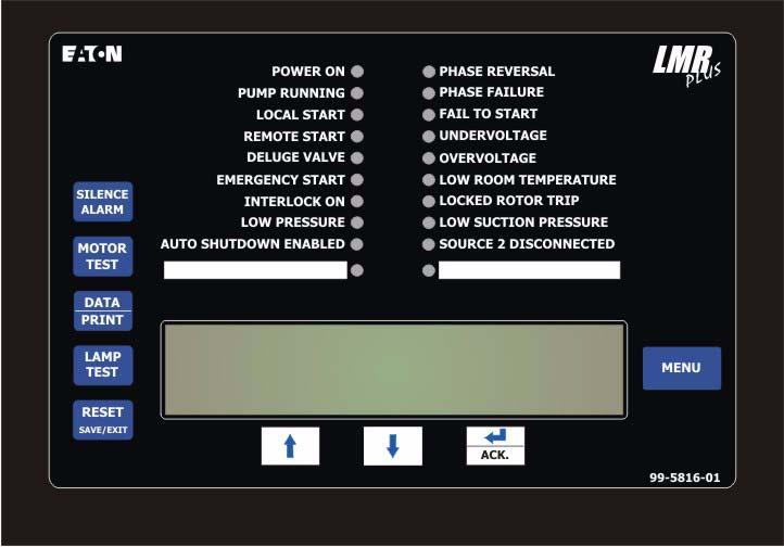
4 The controller should be located or so protected that it will not be damaged by water escaping from pumps or pump connections. Current carrying parts of controllers shall be a minimum of 12 inches (305mm) above the floor. Prior to starting, verify all data on the nameplate such as: catalog number, AC line voltage, horsepower, and frequency. Inspect all electrical connections, components, and wiring for any visible damage. Correct as necessary. Ensure that all electrical connections are tightened before energizing. Refer to the wiring schematic affixed to the enclosure door for all wiring information pertaining to the incoming AC power supply and motor wiring. Install necessary conduit using proper methods and tools. Incoming AC line voltage is clearly marked L1, L2, L3, and ground, located at the top of the enclosure Wire Sizes For control wiring, use #14 AWG wire for all electrical connections. For power wiring sizes refer to Appendix K Electrical Checkout Instructions To ensure the pump does not start upon energizing the controller, the interlock circuit is enabled with the installation of a jumper between terminals 39 and 49. Energize the controller to determine the status of the controller. If it is determined that the controller will not start the motor, this jumper can be removed. The LMR Plus controller is designed to be phase sensitive. L1, L2 & L3 should be connected to A, B & C respectively. Energize the controller by closing the isolation switch (MIS) and circuit breaker (CB). If the phases are connected incorrectly, the 'Phase Reversal' LED on the alarm display will be lit. To correct this condition, refer to Appendix F to correct the phase reversal setting. Re-energize the controller. With the controller energized, operate the 'Start' pushbutton immediately followed by the 'Stop' button to check the rotation of the motor. If the rotation is incorrect disconnect power and reverse connection of the load terminals of the motor contactor T1, T2 & T3. Note: On models Primary Resistor (FD40), Wye Delta (Star-Delta) Open (FD70) and Wye Delta (Star-Delta) Closed (FD80) models, the connection must be changed on both contactors. Adjust the pressure set points detailed in Appendix D. With the controller isolated and the 'Start Pressure' and 'Stop Pressure' values programmed, energize the controller. If the system water pressure is lower than the start pressure, the pump will start. If the controller is set up for fully automatic operation, the pump will stop when the pressure is above the stop point and the running period timer (RPT) has completed its timed interval. If the controller is setup for semi-automatic operation (programmed for manual stop mode), the stop pushbutton must be operated to stop the pump. Note that the system pressure must be equal to or greater than the programmed stop pressure value, otherwise the pump will stop only when the pushbutton is pushed. The circuit breaker setting is factory set and should not be adjusted. The running period timer (RPT) must be set for a minimum of ten (10) minutes. Refer to Appendix E for programming of the RPT. If the sequential start timer (SST) is required refer to Appendix E. If not required set the SST to disabled. If required, the lead pump SST should be set to disabled and the lag SST to five (5) to ten (10) seconds. If there are more than two pumps in the system, allow a ten (10) second delay between pumps. The acceleration timer (AT) is used for reduced voltage controllers only. The AT is factory set based on the starting method of the controller. If it is found that more time is required to allow the pump to come up to speed, the timer may be adjusted to suit. Refer to Appendix E for programming of the AT. If the Undervoltage/Overvoltage alarms are present, check the programmed values by referring to Appendix F. If the values are programmed to their maximum and the alarms continue to occur, check the main voltage supply to ensure that the power available is dependable as per NFPA, Pamphlet 20 standards. 3. HARDWARE DESCRIPTION 3.1 General The purpose of this section is to familiarize the reader with the LMR Plus Controller hardware, its nomenclature, and to list the unit's specifications. 3.2 Front Operator Panel The front operator panel, depending on the installation, is normally accessible from the outside of the door. The front panel provides a means to: Alert the user to specific conditions Program the controller Set and monitor the operating parameters The LMR Plus Controller front panel serves two primary functions: output and input. The output function consists of: A four-line, 40 character LCD display module Twenty LED outputs: Power On, Pump Running, Local Start, Remote Start, Deluge Valve, Emergency Start, Interlock On, Low Pressure, Phase Reversal, EATON CORPORATION Page 4
5 Phase Failure, Fail to Start, Undervoltage, Overvoltage, Low Room Temperature, Locked Rotor Trip, Low Suction Pressure, Auto Shutdown Enabled, Source 2 Disconnected and two (2) user defined LEDs. There are nine input functions accessible via the pushbuttons: Silence Alarm Motor Test Data Print Lamp Test Reset Save/Exit Up Down Ack. Alarm Menu A four-line, 40-character alphanumeric LCD Display module is used to display all LMR Plus monitored parameters, set points, and messages in easy to read formats. The display has a green high contrast background that allows clear visibility of any information displayed. The display is continuously lit for clear visibility under poorly lit or no light conditions. Seven different displays can be presented via the LCD display: Status Display Set Points Display Statistics Display Diagnostics Display Configuration Menu Data/Print Menu Message History Display The "Home" screen display will show the voltages and currents on all three phases, system frequency, system pressure, and the current date and time. The fourth line of the display will also indicate the time remaining on any active timers, alarms without an associated LED, and custom messages The LEDs Power On - This green LED will be illuminated when there is power present in the controller and the microprocessor board is powered up. Pump Running - This green LED will be illuminated once the amperage draw in the controller exceeds 20% of the programmed motor full load amps. Local Start - This green LED will be illuminated when the pump is running after the start pushbutton on the flange has been depressed. Remote Start - This green LED will be illuminated when the pump is running after receiving a start signal on the remote start input. Deluge Valve - This green LED will be illuminated when the pump is running after receiving a start signal from special starting equipment. This is a normally closed contact that is required to be opened to start. Emergency Start - This green LED will be illuminated when the pump is running after the emergency start handle has been depressed and the micro-switch has been activated. Interlock On - This green LED will flash when the interlock input is received, signaling that another controller or device has locked out the controller. Low Pressure - This green LED will flash when the system pressure has dropped below the programmed low-pressure set point. If the pump is running due to a low-pressure condition, this LED will be fully illuminated. Auto Shutdown Enabled - This Green LED will be illuminated when the Auto Shutdown function is enabled. Phase Reversal - This red LED will be illuminated when the controller senses that the input voltage lines are reversed and there is a risk of operating the pump in the reverse direction. Phase Failure - This red LED will be illuminated when at least one of the three phases coming into the controller is missing or the voltage is abnormally low. Fail To Start - This red LED will be illuminated if the amperage draw has not reached 20% of the motor full load amps after the programmed fail to start timer has timed out. Undervoltage - This red LED will illuminate when the system voltage is below the programmed undervoltage alarm. Overvoltage - This red LED will illuminate when the system voltage is above the programmed overvoltage alarm. Low Room Temperature - This red LED will illuminate when the low room temperature signal has been received. A thermostat can be supplied as option R4. Locked Rotor Trip - This red LED will illuminate when the controller has tripped in a locked rotor condition. Low Suction Pressure/Low Foam Level - This red LED will illuminate when the low suction pressure signal has been received. A low suction pressure switch can be added to the controller as option P7. Source 2 Disconnected - This red LED will illuminate if the main disconnect switch on a transfer switch controller is turned off while the controller is energized. Page 5 EATON CORPORATION
6 3.2.2 Pushbuttons Silence Alarm - When an alarm condition exists, the alarm buzzer will sound. If the Silence Alarm button is pressed, the alarm buzzer will turn off. If a subsequent alarm condition occurs after the silence button is pressed, the buzzer will re-sound. Pressing the Silence Alarm button again, will silence the buzzer. Motor Test - Pressing the Motor Test button will simulate an automatic start on the controller due to a low pressure condition. If the Drain Valve menu item is enabled, the controller will energize the drain valve and wait for the panel to be started. If, after one minute, the system does not detect a sufficient pressure drop to start the controller, the drain valve will de-energize and the panel will alarm. The LCD Display will indicate Motor Test Failure. If the drain valve is disabled, the system will simulate a pressure drop and start immediately. All automatic features of the controller such as Run Period Timer and Automatic Shutdown will operate as normal when the Motor Test button is pressed and a low pressure condition is detected. Data Print - The data, print button allows the user to enter a multi-task menu where they can initiate the download of the message history, system diagnostics, system statistics, configuration file to an external USB drive, upload custom messages, and an additional language. If the optional printer (X1) is included with the controller, the user will be able to initiate a print cycle through this menu list. Lamp Test - The lamp test button allows the user to test all of the LED's on the operator panel. Pressing and holding this button will illuminate each LED on the operator panel in successive steps. Reset Save/Exit - The reset/save/exit button serves two functions. Pressing the reset button will reset any alarms that are present on the controller at that time. If the alarm condition still exits it will alarm again. When the user is in the programming mode, pressing the save/exit button will save all of the user adjusted values and make the recent changes active. - The up arrow is used to navigate the main display as well as the menu systems. - The down arrow is used to navigate the main display as well as the menu systems. Ack. - The enter and acknowledge button serves two functions. When navigating the main display, the enter button will allow the user to enter/ exit the message history, statistics, and diagnostics. When in the menu system, the enter button will allow the user to change the programmed set points, and navigate to the next menu item. Menu - Pressing the menu will allow the user access to the programming mode of the controller. When in the programming mode, the menu button will serve as a back button to return to the previous menu heading. 3.3 Display Board Access Area The display board is housed in a protective case that is mounted on the inside of the controller door. Access to communication ports and terminals is possible when the controller door is open. Note: To allow for uniform identification, the frame of reference when discussing the access area is with the panel door open and the user facing the back of the LMR Plus controller. The USB port and I/O board power cable are located on the bottom of the chassis. Optional RS232 and RS485 ports are available. The display contrast adjustments can be made via the open potentiometer dial in the back of the chassis. 3.4 Power I/O Board The Power I/O board is used for all connections pertaining to the operation of the controller. From the remote inputs, starting conditions, and the alarm relay outputs. Refer to the schematic diagram mounted on the inside of the controller door for all connection points specific to the controller. 3.5 Main Isolating Switch/Circuit Interrupter The main isolating switch (MIS) is intended for isolating an electric circuit from its source of power. It has no interrupting rating and must be externally operable. The circuit interrupter (CB) is used to disconnect a running pump motor, if necessary. The CB also provides short circuit protection for the controller and the pump motor and operates in conjunction with the Locked Rotor Protector (LRP). In case of a short circuit the CB will trip instantaneously. In the case of seizure of the pump or motor while starting or running the LRP will trip the CB, via a shunt trip, within twenty (20) seconds, as per NFPA 20 standards. When necessary, a current limiter attachment may be mounted on the bottom of the CB to increase the interrupting capacity. If one or more of the current limiter fuses blows, the cause must be repaired immediately and new current limiters installed when repairs are complete. The isolating switch and circuit interrupter are interlocked so that the enclosure door cannot be opened with the handle in the On position, except by qualified electrical personnel. This is accomplished by the use of EATON CORPORATION Page 6
7 a defeater screw located on the side of the operator handle. Note: The isolation switch is not required on Limited Service controllers. A circuit breaker with a thermal magnetic trip setting between 150 and 250 percent will be used. 3.6 Contactor(s) The contactor(s) (M, in full voltage and soft start controllers; 1M and 2M, in part winding; M and A, in primary resistor; R, S and Y, in autotransformer; 1M, 2M, 1S and 2S, in wye-delta) connect the pump motor to the supply, under control of the pressure switch, start pushbutton, or emergency handle. The contactor coil(s) are connected to the supply voltage of the controller. If a replacement coil is ever required, the correct voltage must be ordered. 3.7 External Pushbuttons Start The start pushbutton is used to initiate a local manual start of the pump motor. Stop The stop pushbutton will initiate the stopping sequence of the fire pump motor. Pressing the stop button will put the controller back into the automatic mode. If a starting condition exists, the pump motor will start again once the stop button is released. 4. OPERATION 4.1 General This section specifically describes the operation and functional use of the LMR Plus controller. The practical use of and operation within each category will be discussed. In this section, it is assumed that prior sections of this manual were reviewed and that the operator has a basic understanding of the hardware. 4.2 Automatic Start / Stop The LMR Plus controller will automatically start and stop the fire pump motor as dictated by the features supplied and their programmed set-point values. A summary of the controller intelligence and supervisory circuits that constantly monitor the condition of the system pressure, inputs, and system alarm points is provided Manual Start Sequence Manual start is defined as a local start, remote start, or emergency start. Whenever the motor is running via a manual start, the motor needs to be manually stopped via the stop pushbutton located on the enclosure flange Automatic Start Sequence Automatic start is defined as a low-pressure condition, deluge valve start or a pump start. Whenever the motor is running via an automatic start, the motor can automatically stop once all starting conditions have returned to normal and the RPT has finished its timing cycle. If the controller is programmed for manual stop, the motor needs to be manually stopped via the local stop pushbutton located on the enclosure flange. 4.3 Control Inputs The LMR Plus has six (6) pre-defined input control signals and nine (9) programmable inputs Control Input Descriptions The Control Input state definitions are as follows. Connected - When the input is shorted by an external contact or connection. Disconnected - When the input is NOT shorted by an external contact or connection. The Control Input operations are defined as follows. Note: Terminal 49 is common to all of the inputs outlined below. Remote Start (Terminal 34) When this input is in the "Connected" state, the LMR Plus controller will initiate a manual start sequence. This input is typically wired to a remote pushbutton to allow for remote manual starting of the controller. Deluge Valve (Terminal 35) When this input is in the "Disconnected" state, the LMR Plus controller will initiate an automatic start sequence. This input is typically wired to remote water control equipment that starts the controller before the pressure transducer does. As this input requires a normally closed contact to open to initiate the start, a jumper is factory installed. The jumper must be removed in order to utilize this optional input. Pump Start (Terminal 36) CAUTION SEVERE DAMAGE COULD BE CAUSED TO THE MICROPROCESSOR BOARDS IF A VOLTAGE IS APPLIED TO THESE INPUTS. THEY ARE INTERNALLY POWERED. When this input is in the "Connected" state, the LMR Plus controller will initiate an automatic start sequence. This input is typically wired to a separate pressure switch when the use of a pressure transducer is not desired. Note: When the controller is programmed for foam operation, the pump start input be a normally closed input that will open to initiate a start. Low Suction/Low Foam Level (Terminal 37) When this input is in the "Connected" state, the LMR Plus controller will signal a visual indication on the main display board for Low Suction. If the controller is Page 7 EATON CORPORATION
8 programmed for Low Suction Shutdown it will initiate the shutdown sequence. Refer to Section 5 to program Low Suction Shutdown. When the controller is setup for a foam system, all references to Low Suction Shutdown will be changed to Low Foam Level. Low Room Temperature (Terminal 38) When this input is in the "Connected" state, the LMR Plus controller will signal a visual indication on the main display board for Low Room Temperature. The Common Alarm relay will also de-energize for remote monitoring of this alarm. Interlock On (Terminal 39) When this input is in the "Connected" state, the LMR Plus controller will not permit a start of the motor except for Emergency Start. This input is typically used in backup style systems. For example, the Engine Running contacts from the backup Diesel Engine Controller are wired into this input. When the Diesel Engine is running, it will lock out the LMR Plus panel and prevent it from starting. Inputs (Terminals 40 to 48) These are programmable inputs and will function based on how they are programmed. Refer to Appendix G(a) for programming details. 4.4 Output Relays The primary control outputs of the LMR Plus controller are dry relay contacts. These relays are comprised of two separate "Form C" outputs for Phase Failure, Phase Reversal, Common Alarm, Pump Run, and Future #1. The alarm relays are UL/CSA rated at 8A 250Vac / 30Vdc. Each relay has a green LED on the I/O board to indicate the relay status. If the LED is "On" the relay is energized and "Off" the relay is de-energized Relay Functions Startup This is the Motor Start relay. It will energize the Run contactor(s), which initiate the motor start. Acceleration This relay is used on reduced voltage starting controllers only. It will energize after the programmed acceleration time delay. It will then switch the motor over to full voltage. Phase Failure This relay is used for remote monitoring of a phase failure alarm condition. In order to ensure dependable operation of this relay it is energized under normal conditions and will de-energize during alarm. This relay can also be used to signal the loss of main power in the fire pump controller. Phase Reversal This relay is used for remote monitoring of a phase reversal condition. The phase reversal alarm is factory set in an ABC configuration. Common Alarm This relay is used to signal any alarm that the LMR Plus controller is alarming on. This relay is energized under normal conditions and will de-energize during alarm. Pump Run This relay is used for remote monitoring when the pump is running. When the amperage draw sensed by the LMR Plus controller exceeds 20% of the motor full load amps, the relay will energize. Future #1 This relay can be programmed for a number of alarm or status conditions. Refer to Appendix G(b) for programming details. 5. PROGRAMMING 5.1 Introduction The LMR Plus controller is fully programmable from the device's faceplate. Users can program set points as well as other parameters. The time, date, and set points can only be changed from the menu system. The menu system is broken down to eight (8) menu groupings. They include, Language, Regional Settings, Pressure Settings, Timer Values, Alarm Set-points, Custom Input/Output, System Configuration Menu, and Main Menu Password. 5.2 Navigation In order to enter the menu system, press the Menu button on the LMR Plus faceplate. If the main menu password has been enabled, the user will be required to enter the password at this time. Once in the menu system, the Up and Down arrow keys will provide navigation between each menu item. The display will show the previous, current, and next menu items. The current menu item is located on the middle of the four line display. All LMR Plus controller programmable features and associated set-point possibilities are presented in Table 1. The following set points are programmable in the LMR Plus controller. EATON CORPORATION Page 8
9 Table 1 Programmable Features and Set points Description Factory Default Range Main Program - (Appendix A) Language (Appendix B) English English/French/Spanish Regional Settings - Appendix C Change Date Current Date Unlimited Change Time Current Time (MST) 24 Hours Pressure Settings - Appendix D Pressure Sensor Enabled Enabled/Disabled Drain Valve Enabled Enabled/Disabled Pressure Start Point 100 PSI PSI Pressure Stop Point 110 PSI PSI Low Pressure Alarm Point 105 PSI PSI High Pressure Alarm Point 300 PSI 0-500PSI Auto Shutdown Automatic Enabled/Disabled Proof Pressure Switch Disabled Enabled/Disabled (Foam Only) Low Suction Shutdown (Foam Level) Disabled Disabled/Enabled Pressure Deviation 10 PSI 1-50 PSI Hourly Pressure Recording Disabled Enabled/Disabled Timer Values - Appendix E Run Period Timer 10 Minutes 0-45 Minutes RPT Start Mode Pump Run Pump Run/Pressure Stop Point Acceleration Timer 2 Seconds 0-10 Seconds Weekly Test Timer Disabled 7 Days/24 Hours (0-60 Minutes) Fail To Start 20 Seconds 0-60 Seconds Fail To Stop 3 Seconds 0-60 Seconds Sequential Start Timer Disabled Disabled / Seconds Alarm Set Points - Appendix F Phase Rotation ABC ABC/CBA Phase Failure Setup 80% % Overvoltage +10% +5-30% / Disabled Undervoltage -10% -5-30% / Disabled Over Frequency +5% +3-10% / Disabled Under Frequency -5% -3-10% / Disabled Audible Common Alarm Disabled Enabled/Disabled Custom Input/Output - Appendix G Custom Inputs #1-9 Undefined Refer to Appendix G(a) Custom Outputs #1-9 Undefined Refer to Appendix G(b) Custom Lights #1-2 Undefined Refer to Appendix G(c) Main Menu Password (Appendix H) Disabled Enabled/Disabled - Any number of four (4) button combinations from keypad Following is a description of each programmable set point. Please Enter Password - If the password is enabled, the user will be prompted to enter the password at this time. If there are no buttons pressed for five (5) seconds, the controller will switch back to the automatic mode. Language - Three (3) languages are offered as standard. They are English, French, or Spanish. A fourth language can be added utilizing the USB port. Consult Eaton for available languages. Refer to Appendix B for programming. Regional Settings - Refer to Appendix C. Following are the descriptions of each menu item: Change Date - Factory set, however, this parameter allows the user to set the current date. Change Time - Factory set to Mountain Standard Time (MST). This menu item allows the user to adjust the time to the local time. The clock is of the 24-hour type. Page 9 EATON CORPORATION
10 Pressure Settings - Refer to Appendix D. Following are the descriptions of each menu item: Pressure Sensor - Some applications do not require a pressure sensor to sense the system pressure in order to start the pump motor when required. In order to accomplish this. The pressure sensor can be disabled through this menu item. Once disabled, the pressure start point, pressure stop point, low pressure alarm, and high pressure alarm set-points will be removed from the menu system. Refer to 4.3 for the Pump Start input to use instead of the pressure sensor. Pressure Start Point - The value programmed determines at which pressure the controller will initiate a start sequence. Pressure Stop Point - The value programmed determines the pressure the system must reach before the controller will automatically stop the fire pump motor, via the running period timer. If the system pressure does not exceed the programmed Pressure Stop Point, the fire pump motor will continue to run. (Auto shutdown only) Low Pressure Alarm - A low pressure alarm point can be selected that will be recorded in the controller's history. High Pressure Alarm - A high pressure alarm point can be selected that will be recorded in the controller's history. Auto Shutdown - The auto shutdown mode is user selectable. If the auto shutdown mode is disabled, the pump motor must be stopped via the local stop pushbutton, whether or not the motor started via an automatic start. If the auto shutdown mode is enabled, the controller will stop the pump motor automatically after all starting causes have been returned to normal and the running period timer has timed out. Proof Pressure Switch - An external pressure switch will activate input # 1, terminal 40. This menu item will only be active when the controller is programmed for a Foam Pump Controller. Low Suction Shutdown/Foam Level - The controller can be programmed to shutdown when a low suction condition is present. If this is desired, the user will select Enabled. There will also be a shutdown delay timer built in (Range: 0-30 Seconds, Default: 10 Seconds) along with the selection of either a Manual or Automatic reset. If Manual Reset is selected, the Ack./Alarm button on the faceplate must be activated to reset the alarm. If an Automatic Reset (default reset mode) is selected, a delay timer (Range: 0-30 Seconds, Default: 10 Seconds) must be set. The controller will then verify if the input is still active, every time the timer times out. If the input is still active the timer will reset and count down again. Once the input has been removed, the timer will start timing. Once the timer has finished timing, out the controller will return to the automatic run mode. When the shutdown delay timer is timing, the time left on the timer will be displayed on the fourth line of the display. When the controller is shutdown on Low Suction, the display will read Low Suction Shutdown. The display will also show the automatic reset time delay when timing. Low Suction Shutdown will not work on Local Starts, Remote Starts, or Emergency Starts. ATTENTION NFPA 20, SECTION 2-9.9, SPECIFICALLY PROHIBITS THE INSTALLATION OF ANY DEVICE IN THE SUCTION PIPING THAT WILL RESTRICT STARTING OR STOPPING OF THE FIRE PUMP. EATON CORPORATION ASSUMES NO LIABILITY WHEN THIS FUNCTION IS USED. Pressure Deviation - A pressure setting may be selected, such that any change in pressure greater than this setting, will record the pressure fluctuation in the alarm memory. Hourly Pressure Recording - The controller can be set so that it will take a pressure reading every hour on the hour. If this feature is not required it can be turned off by selecting Disabled. Timer Values - Refer to Figure #6. Following are the descriptions or each menu item: Run Period Timer (RPT) - The run period timer is used to automatically stop the controller after a programmed time. It can be programmed to operate based on either of two separate conditions, the stop pressure point or when the pump has started to run. If the RPT is programmed to start at the Stop Pressure, the timer will start timing once the system pressure has reached the programmed Stop Pressure Point. If the RPT is programmed to start timing once the pump is running then the timer will start timing once the pump has reached a running condition. If Automatic Shutdown is enabled, the RPT will not be active. It will not start on Remote, Local, and Emergency Starts. While it is timing the amount of time left on the timer will be displayed on the fourth line of the display. RPT Start Mode - The point at which the run period timer starts timing is programmable. If it is programmed to start timing after the pump has started, the RPT will start timing once 20% of the motor FLA has been reached. If it is programmed to start timing once the Stop Pressure Point has been reached, the RPT will start timing when the system pressure has risen above the programmed Pressure Stop Point. EATON CORPORATION Page 10
11 Acceleration Timer (AT) - The acceleration timer can be programmed to allow the controller to run in a reduced voltage state for a period of time. This timer will start timing once a start signal has been received and the startup relay has energized. Weekly Test Timer - A Weekly Timer can be programmed that will automatically start and run the fire pump motor. The Weekly Timer is set by adjusting the day, hour, and minute of the desired weekly run time, the length of time that this test shall be performed, and a Test Interval (TI) (Range 1-52 Weeks) that will run the test every TI weeks. While the weekly test timer is timing, the remaining time will be displayed on the fourth line of the display. Fail To Start Timer (FTS) - The controller will verify that the motor has reached an amperage rating greater that 20% of the programmed motor full load amps when the pump is running. If the amperage has not reached 20% of the motor FLA after the Fail To Start timer has timed out the Fail to Start alarm will be generated. Fail To Stop Timer - The controller will verify that the amperage draw from the motor has dropped below 20% of the programmed motor full load amps when there is a call to stop. If the amperage has not dropped below 20% of the motor FLA, after the Fail To Stop timer has timed out, the Fail to Stop alarm will be generated. Sequential Start Timer (SST) - The SST can be set to delay the starting of the pump when a lowpressure condition exists. If, during the timing of the sequential timer, the pressure rises above the pressure start point, the timer will stop timing and the starting sequence will discontinue. When the SST is timing, the time left will be displayed on the fourth line of the display. The SST will not work on Remote starts, Local starts and Emergency starts. Alarm Set Points - Following are the descriptions for each menu item: Phase Rotation - The user will be able to change the Phase Rotation that the program will base the Phase Reversal alarm on. Overvoltage (OV) - An Overvoltage setting is built into the controller. If the system voltage is above this percentage setting, an alarm will be activated. There is a one (1) second delay before alarming on Overvoltage. Once the condition no longer exists, the alarm will automatically clear. Undervoltage (UV) - An Undervoltage setting is built into the controller. If the system voltage is below this percentage setting, an alarm will be activated. There is a one (1) second delay before alarming on Undervoltage. Once the condition no longer exists, the alarm will automatically clear. Over Frequency (OF) - An Over Frequency setting is built into the controller. If the system frequency is above this percentage setting, an alarm will be activated. Once the condition no longer exists the alarm will automatically clear. There is a three (3) second delay before alarming on Over Frequency. Under Frequency (UF) - An Under Frequency setting is built into the controller. If the system frequency is below this percentage setting, an alarm will be activated. Once the condition no longer exists the alarm will automatically clear. There is a three (3) second delay before alarming on Under Frequency. Custom Input/Output - Refer to Appendix G. Following are the descriptions or each menu item: Custom Inputs - The optional inputs have the ability to be programmed for predetermined values or custom values. The Custom Input Menu will display each input, what it is programmed for and if there are any associated optional relays and / or lights linked to the input. Refer to Table 2 Generic Custom Input Labels for the generic values the optional inputs can be programmed for. When this input is received a message will be stored in memory using the programmed label. Table 2 Generic Custom Input Labels Input Custom Input #1 Relief Valve Discharge Low Oil Pressure Proof Pressure Switch Emergency Switch Open Jockey Pump Run Secondary Pump Run Low Reservoir High Reservoir Pump Room Door Open Supervisory Power Fail Generator Disconnected Label - If the input label is set to Custom Input, this menu item will become active and allow the user to enter the desired input name in. The label will be limited to 20 characters in length and will include all standard ASCII characters. Energize Common Alarm - If required, the common alarm relay (3CR) can be programmed to change states when this input is received. Default value is Disabled. Link to Relay - All inputs can be linked to an output relay. If the relay has been linked to another input or is programmed for another alarm, the program will show that the output is programmed for another alarm and ask if the relay should be reassigned. Default value is Disabled. Page 11 EATON CORPORATION
12 Link to Light - All inputs can be linked to one of the future LED's. If the LED is already linked to another input or is programmed for another alarm, the program will show that the LED is programmed for another alarm and ask if the LED should be reassigned. Default value is Disabled. Latched Until Reset - The alarm signal can be programmed to latch in an on state until the ACK/ ALARM or RESET buttons are pressed. In this case if there are any associated relays or LED's linked to the input, they will stay active until the ACK/ALARM or RESET buttons are pressed. Default value is No. Normal Input State - All inputs can be programmed as normally open or normally closed. Default value is Open. Timer - A timer can be programmed to delay the time before the alarm becomes active. Default value is 0 seconds. Range is seconds. The timer will reset if the input is removed before the time has timed out. Custom Outputs - The optional output relays, as well as the Future #1, relay can be programmed to operate based on generic values. The Custom Output Menu will display each output, what it is programmed for and if there are any associated future inputs and / or lights linked to the output. Please refer to Table 3 for the generic values the optional outputs can be programmed for. Following is a description of the menu items in the Custom Outputs menu. Table 3 Generic Outputs Alarm Low Pressure High Pressure Overvoltage Undervoltage Low Suction Interlock On Fail To Start Pump Running Motor Overload Weekly Test Timing Call to Start Over Frequency Under Frequency Local Start Remote Start Deluge Start Emergency Start Low Pressure Start Pump Start RPT Timing Sequential Start Timing Transducer Failure Backup Battery Low Low Room Temp Alarm Load Shed Fail to Stop Load Shed - When an output is programmed for Load Shed and there is any call to start, except remote start, local start and emergency start, the program will scan the Transfer Switch Emergency Input, terminal 58. If this input is active, the program will energize the assigned output relay and delay the start of the motor until after an adjustable timer period has elapsed. The Load Shed Timer will become active once the Load Shed function is enabled. If the emergency input is not active, the pump will start normally. The load shed relay will return to its normal state once the timer has finished timing. Load Shed Timer - This timer will delay the starting of the motor for a programmed set time as outlined in the previous item. While timing, the remaining time will be displayed on the fourth line of the display. Latched Until Reset - Output relays can be set as latching relays. Pressing the ACK/ALARM or RESET buttons will unlatch them. Default value is No. Fail Safe - Output relays can be programmed to energize under normal conditions (fail safe) or deenergize under normal conditions. Default value is No. Timer - Each output relay can be programmed as a time delay relay. Either as an On delay or as an Off delay. If it is set for On Delay (default) the relay will delay for the programmed time prior to activating the relay. If it is set for Off Delay the relay will activate the relay instantly and then de-activate it after the programmed time. Custom Lights - The two (2) optional LED's can be programmed for alarms that do not have an associated LED or one of the custom inputs. In this section of the program, the LED's can be programmed for one of the values listed in Table 4. As a default the LED's will be programmed for Undefined. Table 4 Custom Lights Alarm High Pressure Motor Overload Weekly Test Timing Over Frequency Under Frequency RPT Timing Sequential Start Timing Transducer Failure Pump Start Battery Backup Low Fail to Stop EATON CORPORATION Page 12
13 6. HISTORY, DIAGNOSTICS AND STATISTICS The LMR Plus controller will record a number of items in its memory to assist with troubleshooting of the system and/or the fire pump controller. These include system history, system statistics, and controller diagnostics. 6.1 System History The LMR Plus controller will record up to 10,000 alarm/ status messages in its memory that can be viewed on the main display, saved to a USB storage device, or viewed on the optional embedded webpage. In order to view the messages on the display press the up or down arrow buttons from the main screen until the display shows "Display Message History". Press the Ack. Alarm button to view the message history. The display will now show three messages at a time. Pressing the up or down arrow buttons will allow navigation showing the most recent message to the oldest message. Refer to Appendix L for common messages and their meaning. Refer to Section 7 to save the message history to a USB storage device or to view the message history on the optional embedded webpage. 6.2 Statistics The LMR Plus controller will record a number of statistical points for a quick review of how the system has been operating. The statistics can be viewed on the main display, saved to a USB storage device, or viewed on the optional embedded webpage. In order to view the statistics on the display press the up or down arrow buttons from the main screen until the display shows "Controller Statistics". Press the Ack. Alarm button to view the statistics. The display will show the statistics that the controller has recorded. Refer to Table 5 for the statistics included with the controller. Refer to Section 7 to save the controller statistics to a USB storage device or to view the message history on the optional embedded webpage. Table 5 Controller Statistics Statistic Range Powered Time Motor Run Time Number of Calls to Start Number of Starts Last Motor Start Date & Time Last Motor Run Time Last Low Pressure Start Date & Time Minimum System Voltage Unlimited Maximum System Voltage Unlimited Minimum System Frequency Unlimited Maximum System Frequency Unlimited Minimum System Pressure Unlimited Maximum System Pressure Unlimited Statistic Last System Startup Last Phase Failure Last Phase Reversal Last Locked Rotor Trip Maximum Run Current Last Locked Rotor Current 6.3 Controller Diagnostics The LMR Plus controller has a number of diagnostic points that can be used to help in troubleshooting issues with the controller. The diagnostics can be viewed on the main display, saved to a USB storage device, or viewed on the optional embedded webpage. In order to view the diagnostics on the display press the up or down arrow buttons from the main screen until the display shows "Controller Diagnostics". Press the Ack. Alarm button to view the diagnostics. The display will show the diagnostics. In order to navigate the diagnostics use the up or down arrow buttons. Note: The diagnostic information shall be provided to personnel trained in the meaning of the values shown. Diagnostic values that are recorded are the current data and time, the microprocessor's firmware version, Eaton's shop order number, customer shop order number, voltage readings, current transformer readings, pressure sensor readings, input status, and output status. Refer to Section 7 to save the controller diagnostics to a USB storage device or to view the message history on the optional embedded webpage. 7. COMMUNICATION The LMR Plus controller is available with a number of communication protocols that can be used for the collection of information that the controller has seen. A USB port is included standard. Optional communications ports are available for Ethernet, Modbus and a Printer. 7.1 USB The USB port is used to download the message history, controller statistics, controller diagnostics, and status to a USB storage device. The USB port can also be used to upload custom messages, additional languages, and update the microprocessor firmware. The USB memory device must meet the following requirements: Maximum memory size: 2GB USB 1.0 or 2.0 Formatted with Fat 16 protocol. Range Date & Time Date & Time Date & Time Date & Time Unlimited Unlimited Page 13 EATON CORPORATION

14 Information Download In order to download the history, diagnostics, statistics, and status, install a USB storage device into the USB port on the display board. With the power on, press the Data Print button. The first selection is "Save to USB". Press the Ack. Alarm button and the controller will save the information to the USB storage device. There will be five (5) files saved to the disk drive. Refer to Table 6 for the file nomenclature. Table 6 File Nomenclature File Nomenclature Description ARC00000.csv ARC=Archive Message 00000=Serial number history STC00000.txt STC=Statistics Controller 00000=Serial number statistics DIA00000.txt DIA=Diagnostics Controller 00000=Serial number diagnostics STA00000.txt STA=Statistics Controller 00000=Serial number status CON00000.txt CON=Configuration Controller 00000=Serial number configuration The.csv file is a comma separated values file that can be opened using standard spreadsheet, word processor, or database programs. The.txt files can be opened using standard text viewers. Custom Message Upload The LMR Plus controller has the ability to store and use up to ten (10) custom messages that can appear based on a specific date, time, alarm or status condition. Refer to Appendix J to upload and enable the custom messages. Refer to Section 8 for the creation of the custom message file. Firmware Update Contact the factory or an authorized trained representative for assistance. Language Upload Contact the factory or an authorized trained representative for assistance. 7.2 Embedded Webpage * The controller has a built-in webpage that can be used to view the main display of the controller and its current status. * COM Option must be ordered for this function. Contact the factory or an authorized trained representative for assistance in accessing the webpage. 7.3 RS485 Serial Port * An optional RS485 serial port can be provided for communication to various external software programs including Modbus. *COM Option must be ordered for this function. 7.4 RS232 Serial Port * This optional port is used with the optional printer (X1) to initiate a print cycle. *COM Option must be ordered for this function. 8. CUSTOM MESSAGES In order to upload custom messages to the controller a file needs to be created. This section outlines the file format and trigger points required to use the custom messages. All that is required to create the custom message file is a standard spreadsheet program. Specific software is not required. Ten (10) custom messages can be saved in the file and uploaded to the controller for use. Each message will be entered in the first ten (10) rows of the spreadsheet. Do not use the top row as a heading row. There are five (5) trigger points that can be used. They include specific date and time range, number of pump start events, number of hours run, specific alarms, or common alarm. Figure 1 shows examples of the custom messages and how the file needs to be laid out. Following is a description of each column and the data required to be entered in the column. Figure 1 Custom Message Examples Column A contains the message that will scroll along the fourth line of the display. The message can be up to one hundred (100) characters in length. Column B contains the message type reference number. Refer to Table 7 for the message types. Table 7 Custom Message Types Number Description 1 Specific date and time range 2 Number of pump start events 3 Number of hours run 4 Specific alarms 5 Common Alarms EATON CORPORATION Page 14
15 Column C and D are used to determine when the custom message will appear. Refer to the following for specific notes regarding each tripper point. Date and Time Range (1) Column C is used for the date and time that the message will start and column D is used for the date and time that the message will stop. The date and time format is as follows: MMDDYYHHMM = Month Day Year Hour Minute If any value entered between 1 and 9 needs to be lead by a 0. For example, January 1, 2007, 8:15AM needs to be entered as Note: All cells need to be formatted as text. Number of Pump Start Events (2) Column C is used to enter the number of pump starts before the message will appear. The format is as follows: XXXXX = Number of Pump Start Events For example to have the message appear after 25 pump start events it will be entered as Note: All cells need to be formatted as text. Number of Hours Run (3) Column C is used to enter the number of hours the pump has run before the message will appear. The format is as follows: XXXXX = Number of Hours Run For example, to have the message appear after 125 hours of running the trigger point will be entered as Note: All cells need to be formatted as text. For detailed instructions, refer to Technical Services Brochure - FPCTB-RH012 - Rev A. Specific Alarms (4) Column C is used to enter the alarm event number. Refer to Table 8 for the alarm events and their corresponding number. Number Event 10 Deluge Valve Off 11 Low Foam Level 12 Low Pressure 13 Low Room Temperature 14 Over Frequency 15 Under Frequency 16 Transducer Failure Note: All cells needs to be formatted as text. Common Alarm (5) No other points are required to be entered into the spreadsheet, as this message will appear anytime there is an alarm. Table 8 Specific Alarm Events Number Event 01 Overvoltage (Phase A, B, or C) 02 Undervoltage (Phase A, B, or C) 03 Phase Failure (Phase A, B, or C) 04 Phase Reversal 05 Low Suction 06 Relief Valve Open 07 Fail to Stop 08 Fail to Start 09 Locked Rotor Trip Page 15 EATON CORPORATION
16 APPENDIX A: MAIN MENU TREE EATON CORPORATION Page 16
17 APPENDIX B: LANGUAGE MENU TREE Page 17 EATON CORPORATION
18 APPENDIX C: REGIONAL SETTINGS MENU TREE EATON CORPORATION Page 18
19 APPENDIX D: PRESSURE SETTINGS MENU TREE Page 19 EATON CORPORATION
20 APPENDIX E: TIMER VALUES MENU TREE EATON CORPORATION Page 20
21 APPENDIX F: ALARM SETPOINTS MENU TREE Page 21 EATON CORPORATION
22 APPENDIX G: CUSTOMER INPUT/OUTPUT MENU TREE EATON CORPORATION Page 22
23 APPENDIX G(A): CUSTOM INPUTS MENU TREE Page 23 EATON CORPORATION
24 APPENDIX G(B): CUSTOM OUTPUTS MENU TREE EATON CORPORATION Page 24
25 APPENDIX G(C): CUSTOM LIGHTS MENU TREE Page 25 EATON CORPORATION
26 APPENDIX H: MAIN MENU PASSWORD MENU TREE EATON CORPORATION Page 26
27 APPENDIX J: CUSTOM MESSAGE LOAD & ACTIVATION Page 27 EATON CORPORATION
28 APPENDIX K: POWER WIRE CABLE REFERENCE Line Terminals on Main Isolation Switch (Incoming Cables) Line Voltage Qty. & Cable Sizes Service Entrance GND. LUG V V * V V V Qty. & Cable Sizes Max HP (1)#14-1/0 Per Ø (CU/AL) (1)#14-2/0 (CU/AL) (1)#4-4/0 Per Ø (CU) (1)#4-350MCM (CU/AL) (1)#3-350MCM Per Ø (1)#4-350MCM (CU/AL) (CU/AL) (2)3/0-250MCM Per Ø (2)1/0-750MCM (CU/AL) (CU/AL) (2) MCM Per Ø (2)1/0-750MCM (CU/AL) (CU/AL) (2)#1-500MCM PER Ø (2)1/0-750MCM (CU/AL) (CU/AL) (3)3/0-400MCM PER Ø (CU/AL) (2)1/0-750MCM (CU/AL) * Coils available: 380V-50Hz, 380V-60Hz, 415V-50Hz, 415V-60Hz Service Entrance Ground Lug Line Voltage Qty. & Cable Sizes V V V V V Max HP (1)#14-2/0 (CU/AL) (1)#14-2/0 (CU/AL) (1)#4-350MCM (CU/AL) (2)#4-350MCM (CU/AL) (2)#2-600MCM (CU/AL) *For proper cable size, refer to the National Electrical Code NFPA-70 EATON CORPORATION Page 28
29 APPENDIX L: ALARM/STATUS MESSAGES Message ATS IN EMERGENCY ATS IN NORMAL DELUGE VALVE START EMERGENCY START FAIL TO START FAIL TO STOP FREQUENCY OK GENERATOR DISCONNECT HIGH PRESSURE INTERLOCK OFF INTERLOCK ON INTERLOCK SHUTDOWN JOCKEY RUNNING JOCKEY STOPPED LOAD SHED CLOSED LOCAL START LOCAL STOP LOCKED ROTOR TRIP LOW FOAM SHUTDOWN LOW PRESSURE LOW PRESSURE ALARM LOW PRESSURE OK LOW PRESSURE START LOW ROOM TEMPERATURE LOW SUCTION LOW SUCTION SHUTDOWN MENU ENTERED MOTOR OVERLOAD OV PHASE AB OV PHASE BC OV PHASE CA OVER FREQ PHASE A FAILURE PHASE A OK PHASE B FAILURE PHASE B OK PHASE C FAILURE PHASE C OK PHASE REVERSAL PHASE REVERSAL OK PRESSURE = 000 PUMP RUNNING PUMP START PUMP START OFF Description The automatic transfer switch is in the emergency position The automatic transfer switch is in the normal position The controller started the motor after it received a deluge valve start signal The emergency start handle was pressed in and the motor started There was a call to start the motor, however, the amperage draw did not reach 20% of the programmed motor full load amps If the amperage draw has not dropped below 20% of the programmed motor full load amps two (2) seconds after a stop command, this alarm will be triggered The system frequency has come back into normal operating levels and the alarm has been cleared The isolation switch on the automatic power transfer switch is in the open position The system pressure is above the programmed high pressure alarm set point The interlock signal has been removed The interlock signal has been received The pump has been shutdown due to an interlock signal The jockey pump running signal has been received The jockey pump running signal has been removed The load shed timer has started timing and the load shed output has closed The start pushbutton on the enclosure flange was pressed initiating a start sequence The stop pushbutton on the enclosure flange was pressed initiating a stop sequence The controller has tripped on the built in locked rotor over current protection The controller has shutdown after receiving a low foam level signal The system pressure has dropped below the programmed pressure start point The system pressure has dropped below the programmed low pressure alarm point The system pressure has risen above the programmed pressure stop point The pump has started running because of a low pressure condition The controller has received a low room temperature signal The controller has received a low suction signal The controller has shutdown because of low suction The menu system was entered by a user The amperage draw has exceeded 125% of the programmed motor full load amps The voltage measured between phase A and B has exceeded the programmed overvoltage alarm set point The voltage measured between phase B and C has exceeded the programmed overvoltage alarm set point The voltage measured between phase C and A has exceeded the programmed overvoltage alarm set point The system frequency has exceeded the programmed over frequency set point The controller has detected a phase failure on phase A The phase failure alarm detected on phase A has been cleared The controller has detected a phase failure on phase B The phase failure alarm detected on phase B has been cleared The controller has detected a phase failure on phase C The phase failure alarm detected on phase C has been cleared The controller has detected a phase reversal on the system voltage The phase reversal alarm has been cleared System pressure readings the controller has recorded The amperage draw on the motor has reached at least 20% of the programmed motor full load amps The pump has started via a pump start signal The pump start signal has been removed Page 29 EATON CORPORATION
30 Message PUMP STOPPED REMOTE START ROOM TEMPERATURE OK RPT TIMED OUT SEQ START DELAY SST STOPPED SYSTEM STARTUP TRANSDUCER FAILURE TRANSDUCER OK UV PHASE AB UV PHASE BC UV PHASE CA WEEKLY TEST DONE WEEKLY TEST START WEEKLY TEST STOP Description The pump has stopped after a stop sequence has been initiated The pump has stated via a remote start signal The low room temperature alarm has cleared The running period timer has finished its timing cycle A start sequence has been started, however, it is delayed due to the programmed sequential start timer The sequential start timer has stopped timing Power has been reapplied to the system and a successful system boot has been completed The controller has detected that the transducer has failed The controller has detected that the transducer is in good working condition The voltage measured between phases A and B has dropped below the programmed undervoltage set point The voltage measured between phases B and C has dropped below the programmed undervoltage set point The voltage measured between phases C and A has dropped below the programmed undervoltage set point The weekly test has been completed The pump has started on a weekly test The pump has stopped after a weekly test cycle EATON CORPORATION Page 30
31 NOTES: Page 31 EATON CORPORATION

32 Effective July 2011 This information booklet is published solely for information purposes and should not be considered allinclusive. If further information is required, you should consult EATON. Sale of product shown in this literature is subject to terms and conditions outlined in appropriate EATON selling polices or other contractual agreement between the parties. This literature is not intended to and does not enlarge or add to any such contract. The sole source governing the rights and remedies of any purchaser of this equipment is the contract between the purchaser and EATON. NO WARRANTIES, EXPRESSED OR IMPLIED, INCLUDING WARRANTIES OF FITNESS FOR A PARTICULAR PURPOSE OR MERCHANTABILITY, OR WARRANTIES ARISING FROM COURSE OF DEALING OR USAGE OF TRADE, ARE MADE REGARDING THE INFORMATION, RECOMMENDATIONS AND DESCRIPTIONS CONTAINED HEREIN. In no event will EATON be responsible to the purchaser or user in contract, in tort (including negligence), strict liability or otherwise for any special, indirect, incidental or consequential damage or loss whatsoever, including but not limited to damage or loss of use of equipment, plant or power system, cost of capital, loss of power, additional expenses in the use of existing power facilities, or claims against the purchaser or user by its information, recommendations and description contained herein Eaton Industries Canada All Rights Reserved Printed in Canada Publication No. IM K September 2013 Eaton Industries Canada th Street NE, # 124 Calgary, Alberta, Canada T3N 0A4 Phone: Fax: chcfirepump@eaton.com
FD30 Full Voltage - Across the Line July 2011
 Must Be Installed Per Applicable Code and Manufacturers Recommendations Electric Fire Pump Controllers Features 1-1 FD30 Full Voltage - Across the Line July 2011 Power I/O Board Transformers Incoming line
Customer Connection Terminals Connection terminals for external customer connections, are located at the top of the Power I/O board.
 Must Be Installed Per Applicable Code and Manufacturers Recommendations Electric Fire Pump Controllers Features 1-1 FD80 Reduced Voltage - Wye Delta (Star-Delta) Closed Transition Power I/O Board Transformers
Fire Pump Controllers Foam (Additive) Controllers
 Controllers") Fire Pump Controllers Foam (Additive) Controllers Diesel Additive (Foam) Pump Controllers 1.4 Foam (Additive) Fire Pump Controllers FDF20 Foam (Additive) - Limited Service... FDF30 Foam (Additive) - Across-the-Line...
Fire Pump Controllers Foam (Additive) Controllers Diesel Additive (Foam) Pump Controllers 1.4 Foam (Additive) Fire Pump Controllers FDF20 Foam (Additive) - Limited Service... FDF30 Foam (Additive) - Across-the-Line...
FT20 Full Voltage - Limited Service. Electrically and Mechanically
 LMR PLUS Electric Fire Pump Controllers with Transfer Switch FT20 Full Voltage - Limited Service 1-1 May 2014 Product Description The Automatic Transfer Switch Option may be added to any FD type Fire Pump
FT40 Reduced Voltage - Part Winding. Electrically and Mechanically
 LMR PLUS Electric Fire Pump Controllers with Transfer Switch Features FT40 Reduced Voltage - Part Winding 1-1 January 2012 Product Description The Automatic Transfer Switch Option may be added to any FD
DIESEL Engine Fire Pump Controllers Features. FD120 Diesel Engine Controllers
 DIESEL Engine Fire Pump Controllers Features FD120 Diesel Engine Controllers 1-1 March 2013 Diesel Product Description The DIESEL Plus Fire Pump Controllers from Eaton Corporation are designed to control
Fire Pump Controllers Medium Voltage Controllers
 Fire Pump Controllers Medium Voltage Controllers Medium Voltage Controllers 1.5 Medium Voltage Fire Pump Controllers FDM Medium Voltage... Part Number / Options Selection Guide... Product Specifications
LMR Electric Fire Pump Controllers Features
 1-1 Printer / Recorder The industrial grade thermal printer is housed in a rugged steel enclosure within the controller. The on/off switch, feed and reset buttons are front accessible. A bi-color status
LMR Electric Fire Pump Controllers Features
 1-1 Printer / Recorder The industrial grade thermal printer is housed in a rugged steel enclosure within the controller. The on/off switch, feed and reset buttons are front accessible. A bi-color status
FT60 Reduced Voltage - Autotransformer
 1-1 Product Description The Automatic Transfer Switch Option may be added to any FD type Fire Pump Controller whenever automatic transfer from normal to alternate power is required. The automatic Transfer
Transfer Switch Features
 1-1 Product Description The Automatic Transfer Option may be added to any FD type Fire Pump Controller whenever automatic transfer from normal to alternate power is required. The automatic Transfer and
FDF Foam Pump Controllers Features
 FDF100 Diesel Engine Foam Pump Controllers 1-1 Product Description The FDF Series of Foam Pump Controllers are designed for use with foam concentrate injection, foam transfer and water mist systems for
DIESEL Engine Fire Pump Controllers Features
 September 007 DIESEL Engine Fire Pump Controllers Features FD0 Diesel Engine Controllers 1-1 Printer / Recorder The industrial grade thermal printer is housed in a rugged steel enclosure within the controller.
EATON DFDAP-M / FDAP-M Remote Alarm Panels
 O & M Manual IM05805008K O & M Manual IM05805008K TABLE OF CONTENTS 1. INSTALLATION AND MOUNTING OF THE CONTROLLER 1 2. ELECTRICAL CONNECTIONS 1 2.1 ELECTRICAL CHECKOUT INSTRUCTIONS 2 2.2 ELECTRIC ALARM
DIESEL Engine Fire Pump Controllers Features
 1-1 Product Description The FD100 Diesel Engine Controller is designed to control and monitor 12 or 24 volt, diesel fire pump engines. All models are listed by UL and ULC, and approved by Factory Mutual
Transfer Switch Features
 1-1 Product Description The Automatic Transfer Switch Option may be added to any FD type Fire Pump Controller whenever automatic transfer from normal to alternate power is required. The automatic Transfer
ELECTRIC FIRE PUMP CONTROLLER
 ELECTRIC FIRE PUMP CONTROLLER INSTRUCTION MANUAL CONTENTS 1. INTRODUCTION 1.1 Safety 1.2 Warranty 1.3 Safety Precautions 1.4 Product Overview 1.5 AS2941-2008 Requirements 2. FEATURES 3. FUNCTIONS AND OPERATIONS
Soft Start Series MP700 Solid State, Reduced Voltage
 Metron Fire Pump Controls and Accessories Soft Start Series MP700 Solid State, Reduced Voltage Metron Fire Pump Controllers conform to the latest requirements of National Fire Protection Association s
Project: Customer: Engineer: Pump Manufacturer: Model GPY + GPU. with Automatic Power Transfer Switch
 Project: Customer: Engineer: Pump Manufacturer: Model GPY + GPU with Automatic Power Transfer Switch Contents: NOTE: The drawings included in this package are for controllers covered under our standard
Drawing Submittal Package
 Project: Customer: Engineer: Pump Manufacturer: Drawing Submittal Package Model GPL + GLU Limited Service Full Voltage Across the Line Start Electric Pump Controller with Automatic Power Transfer Switch
Across-the-Line SERIES MP300 Combined Manual and Automatic
 Across-the-Line SERIES MP300 Combined Manual and Automatic Metron Fire Pump Controllers conform to the latest requirements of National Fire Protection Association s Standard for Centrifugal Fire Pumps
Model VPS Pressure Limiting (VFD) Electric Fire Pump Controller with Soft Start Bypass
 Electric Fire Pump Controller with Soft Start Bypass") Project: Customer: Engineer: Pump Manufacturer: Submittal Document Model VPS Pressure Limiting (VFD) with Soft Start Bypass Contents: Data Sheets Dimensional Data Wiring Schematics Field Connections Note:
Project: Customer: Engineer: Pump Manufacturer: Submittal Document Model VPS Pressure Limiting (VFD) with Soft Start Bypass Contents: Data Sheets Dimensional Data Wiring Schematics Field Connections Note:
Model VPS + VPU Pressure Limiting (VFD) Electric Fire Pump Controller with Soft Start Bypass with Automatic Power Transfer Switch
 Electric Fire Pump Controller with Soft Start Bypass with Automatic Power Transfer Switch") Project: Customer: Engineer: Pump Manufacturer: Technical Data Submittal Document Model VPS + VPU Pressure Limiting (VFD) with Soft Start Bypass with Automatic Transfer Switch Contents: Data Sheets Dimensional
Project: Customer: Engineer: Pump Manufacturer: Technical Data Submittal Document Model VPS + VPU Pressure Limiting (VFD) with Soft Start Bypass with Automatic Transfer Switch Contents: Data Sheets Dimensional
Drawing Submittal Package
 Project: Customer: Engineer: Pump Manufacturer: Drawing Submittal Package Model GPL + GLU Limited Service Full Voltage Across the Line Start Electric Pump Controller with Automatic Power Transfer Switch
Variable Frequency Drive SERIES MP800 VFD
 Metron Fire Pump Controls and Accessories Variable Frequency Drive SERIES MP800 VFD Metron Fire Pump Controllers conform to the latest requirements of National Fire Protection Association s Standard for
Fire Pump Controller. For Electric Motor Driven Fire Pumps. Wye Delta Reduced Current Types
 Fire Pump Controller For Electric Motor Driven Fire Pumps Wye Delta Reduced Current Types Series MP430 and Series MP435 Combined Manual and Automatic Metron Fire Pump Controllers conform to the latest
MPT Electric Fire Pump Controller
 Setup and Operating Instructions MPT Electric Fire Pump Controller This manual provides general information, installation, operation, maintenance, and system setup information for Metron MPT Electric Fire
WITH POWER TRANSFER SWITCH STANDARD SUBMITTAL PACKAGE
 WITH POWER TRANSFER SWITCH STANDARD SUBMITTAL PACKAGE SBP1000-61 FTA1000 Full Voltage Starting Electric Fire Pump Controllers Product Description Description Firetrol FTA1000 Full Voltage Fire Pump Controllers
MASTER JOCKEY PUMP CONTROLLER. Model JPCE INSTRUCTION MANUAL. C 2018 Master Control Systems, Inc
 MASTER JOCKEY PUMP CONTROLLER Model JPCE INSTRUCTION MANUAL C 2018 Master Control Systems, Inc TABLE OF CONTENTS Important Safety Information. Page 3 General Description and Installation.. Page 4 Model
MASTER PRESSRE MAINTANENCE CONTROLLER. Models PMCE INSTRUCTION MANUAL. C 2018 Master Control Systems, Inc
 MASTER PRESSRE MAINTANENCE CONTROLLER Models PMCE INSTRUCTION MANUAL C 2018 Master Control Systems, Inc TABLE OF CONTENTS Important Safety Information. Page 3 General Description and Installation.. Page
Technical Data Submittal Document
 Project: Customer: Engineer: Pump Manufacturer: Technical Data Submittal Document Model GPL + GLU Limted Service Full Voltage Across the Line Start Electric Fire Pump Controller Contents: Data Sheets Dimensional
ModSync Sequencing System Installation & Operation Manual. For use with Fulton Steam Boilers.
 ModSync Sequencing System Installation & Operation Manual For use with Fulton Steam Boilers. Revision 3.0 8/21/2008 - 2 - Table of Contents Introduction Page 4 Features Page 4 Sequence of Operation Page
MANUAL FOR MODEL MP600 HIGH VOLTAGE ELECTRIC MOTOR DRIVEN FIRE PUMP CONTROLLERS
 MANUAL FOR MODEL MP600 HIGH VOLTAGE ELECTRIC MOTOR DRIVEN FIRE PUMP CONTROLLERS Starting Serial No. "LH" This manual provides General Information, Installation, Operation, Maintenance and System Set-Up
NS (A) ECN
 ECN") Installation and Operation Instructions Mark IIXG Diesel Engine Fire Pump Controllers FTA00 NS00-50(A) ECN 237793 Table of Contents INTRODUCTION... MOUNTING CONTROLLER... Wall Mount... - 2 Floor/Base Plate
Installation and Operation Instructions Mark IIXG Diesel Engine Fire Pump Controllers FTA00 NS00-50(A) ECN 237793 Table of Contents INTRODUCTION... MOUNTING CONTROLLER... Wall Mount... - 2 Floor/Base Plate
Powerohm Resistors Digital HRG System
 Installation and Operating Instructions Powerohm Resistors Digital HRG System This manual provides general information, installation, operation, maintenance, and system setup information for the Powerohm
CONTROL PANEL INTERFACE ACTIVATE THE GENERATOR DISPLAY INTERFACE MENUS. Control Panel USING THE AUTO/OFF/MANUAL SWITCH
 CONTROL PANEL INTERFACE USING THE AUTO/OFF/MANUAL SWITCH With the switch set to AUTO, the engine may crank and start at any time without warning. Such automatic starting occurs when utility power source
Instruction manual MTL process alarm equipment. October 2016 CSM 725B rev 2 MTL RTK 725B. Configuration Software Manual
 Instruction manual MTL process alarm equipment October 2016 CSM 725B rev 2 MTL RTK 725B Configuration Software Manual SECTION 1 - INTRODUCTION... 5 Basic Requirements... 5 SECTION 2 - SOFTWARE INSTALLATION...
User s Manual. TIGER S EYE E-Series Mark V Jockey. TIGERFLOW Systems, Inc Mint Way Dallas, Texas
 User s Manual TIGER S EYE E-Series Mark V Jockey TIGERFLOW Systems, Inc. 4034 Mint Way Dallas, Texas 75237 214-337-8780 www.tigerflow.com TABLE OF CONTENTS Introduction... 4 Sequence of Operation... 5
DATA SHEET CHEETAH XI 50 INTELLIGENT SUPPRESSION CONTROL SYSTEM DESCRIPTION APPROVALS: SYSTEM OPERATION. Form No. D
 DATA SHEET CHEETAH XI 50 INTELLIGENT SUPPRESSION CONTROL SYSTEM DESCRIPTION Fike s Cheetah Xi 50 (P/N 10-071) is a state-of-the-art true intelligent digital peer-to-peer modular suppression control system.
Remote Alarm Panels Features
 Features 1-1 DFDAP-M / FDAP-M Remote Product Description Eaton s Remote s are designed to provide audible and visual alarms for Electric and Diesel Fire Pump Controllers. These remote panels are located
User Manual. Dryer Controller M720
 User Manual Dryer Controller M720 Hardware version 1.00 Software version 1.00 Preliminary version Manual M720 Dryer controller Page 1 of 42 Document history Preliminary version: - Created in April, 2009
Refer to Bulletin E-1101 for detailed information on the FLAME-MONITOR System.
 The Fireye EP260, EP270 (early spark termination), or EP265 (pilot stabilization) programmer modules are used with the FLAME-MONITOR Burner Management Control System (P/N E110). Several operational characteristics
Dryer Controller M720
 User Manual Dryer Controller M720 Hardware version 2.00 Software version 2.00 Manual M720 Dryer controller Page 1 of 60 Document history Preliminary version: - Created in April, 2009 Hardware Version 2.00,
GG-2 2-CHANNEL GAS DETECTION CONTROL PANEL. Installation and Operation Manual
 GG-2 2-CHANNEL GAS DETECTION CONTROL PANEL Installation and Operation Manual 2 GG-2 Warning Use this product only in the manner described in this manual. If the equipment is used in a manner not specified
Static Pressure Control
 The (model SPC-2) is a fully programmable controller that provides extensive flexibility for your curtain or awning control needs. The SPC-2 automatically controls the pressure in a room by operating a
SPECIFICATION MICROMIST FIRE SUPPRESSION SYSTEM WITH SHP-PRO CONTROL PANEL
 SECTION 1 - GENERAL CONDITIONS I. SCOPE: This specification outlines the requirements for a Fike Micromist Water Mist Fire Suppression System with automatic detection and control. The work described in
ZX1e ZX2e ZX5e. Document No Issue 01 user manual
 ZX1e ZX2e ZX5e Document No. 996-130 Issue 01 user manual MORLEY-IAS ZX2E/ZX5E Fire Alarm Control Panels Table of Contents 1 INTRODUCTION... 4 1.1 NOTICE... 4 1.2 WARNINGS AND CAUTIONS... 4 1.3 NATIONAL
Operating & Maintenance Manual. Alert-4 Ethernet LCD Master Alarm
 Operating & Maintenance Manual Alert-4 Ethernet LCD Master Alarm w w w. a m i c o. c o m Contents User Responsibility 4 Introduction 4 Features 5 Description of the Alarm 5 Shipment Details 5 The Alarm
MPT Electric Fire Pump Controller
 MPT Electric Fire Pump Controller Alarm Messages and Guide This manual provides alarm descriptions, troubleshooting steps, and alarm set point configuration information for Metron MPT Fire Pump Controllers
GASGUARDIAN Channel Controller OPERATING & INSTALLATION MANUAL
 GASGUARDIAN 2 3 2-Channel Controller OPERATING & INSTALLATION MANUAL GasGuardian 2 3 Operating and Installation Manual Table of Contents General description.... 3 Installation. 3 Locating the GasGuardian-2..
DATA SHEET CYBERCAT 254 INTELLIGENT FIRE ALARM CONTROL SYSTEM DESCRIPTION APPROVALS: SYSTEM OPERATION. Form No. D
 DATA SHEET CYBERCAT 254 INTELLIGENT FIRE ALARM CONTROL SYSTEM DESCRIPTION Fike s CyberCat 254 (P/N 10-066) is a state-of-the-art true intelligent digital peer-to-peer modular fire alarm control system.
Section 8 System Operation
 Section 8 System Operation Operation of the control panel is simple. Menus guide you step-by-step through operations. This section of the manual is an overview of the operation menus. Please read this
MODEL GPT-130 SINGLE POINT HEAT TRACE CONTROL THERMOSTAT
 TRACON MODEL GPT-130 SINGLE POINT HEAT TRACE CONTROL THERMOSTAT TABLE OF CONTENTS GPT 130 Overview... 2 Installation... 3 Power Source and Load Connection... 4 Temperature Sensor Installation... 5 Panel
Replaceable LED modules. Sleep or unattended mode. Auto-silence and auto-acknowledge
 Replaceable LED modules 11 Alarm Sequences as per ISA-18.1 standard Each channel/window fully field programmable RS232 or RS485 MODBUS-RTU communication Repeat relay for each window and multifunction relays
MYRIAD TRIPLEX PUMP CONTROLLER INSTRUCTION MANUAL
 MYRIAD TRIPLEX PUMP CONTROLLER INSTRUCTION MANUAL MYRIAD TPC VISIT OUR WEBSITE SIGMACONTROLS.COM MYRIADI&O062705 2 TABLE OF CONTENTS INTRODUCTION 3 Ordering Information Specifications Features WIRING 7,8
Dual Point General Purpose Heat Trace Control TRACON MODEL GPT 230 Installation and Operation Manual
 We manage heat MANUAL Dual Point General Purpose Heat Trace Control TRACON MODEL GPT 230 Installation and Operation Manual 1850 N Sheridan Street South Bend, Indiana 46628 (574) 233-1202 or (800) 234-4239
Installation and Operation Manual
 SENTRY Protect Plus QUADPLEX PANEL Installation and Operation Manual For Hardwired Pumps Environment e Corporation Table of Contents 1 Overview...3 2 Sentry Protect Plus Quadplex Menu Flowchart...4 3 Wiring
Section 9 System Operation
 Section 9 System Operation Operation of the control panel is simple. Menus guide you step-by-step through operations. This section of the manual is an overview of the operation menus. Please read this
PHYSICAL FACILITIES Consultant s Handbook Specifications Division 21 Fire Suppression 3000 Fire Pumps
 Note: The A/E must choose all design values in brackets below before using in project specifications 1 General 1.1 Provide UL listed and FM approved fire pump complete with pump, driver, controller and
Beacon 800 Gas Monitor Operator s Manual
 Beacon 800 Gas Monitor Operator s Manual Part Number: 71-0037RK Revision: F Released: 4/18/17 www.rkiinstruments.com Product Warranty RKI Instruments, Inc. warrants gas alarm equipment sold by us to be
PowerWizard. Level 1.0 & Level 2.0 Control Systems Training
 PowerWizard Level 1.0 & Level 2.0 Control Systems Training New Systems Current Systems Systems Comparison Level 1 Level 2 Level 3 Level 4 PowerWizard Level 3.0 PowerWizard Level 4.0 Overview Common parts
Dryer Master Inc. Dryer Master AM 3. Product Manual
 Dryer Master Inc. Dryer Master AM 3 Revision 1.0 July, 2008 Revision 1.2 February, 2009 Revision 1.3 March, 2009 Revision 1.4 September, 2013 Prepared by: Dryer Master Inc. Dryer Master Inc 2008, 2009,
PEGAsys. Multi-Loop Intelligent Suppression Control System FEATURES DESCRIPTION. Effective: March 2007 K
 PEGAsys Multi-Loop Intelligent Suppression Control System A UTC Fire & Security Company Effective: March 2007 K-76-028 FEATURES UL Listed CSFM Approved MEA Approved Peer-to-Peer Networking (to 32 nodes)
1.1 REFERENCES.1 American National Standards Institute/National Fire Protection Association (ANSI/NFPA).1 ANSI/NFPA 20, Centrifugal Fire Pumps.
.1 ANSI/NFPA 20, Centrifugal Fire Pumps.") Issued 2006/08/01 Section 13920 Packaged Fire Pumps and Controllers Page 1 of 7 PART 1 GENERAL 1.1 REFERENCES.1 American National Standards Institute/National Fire Protection Association (ANSI/NFPA).1
Issued 2006/08/01 Section 13920 Packaged Fire Pumps and Controllers Page 1 of 7 PART 1 GENERAL 1.1 REFERENCES.1 American National Standards Institute/National Fire Protection Association (ANSI/NFPA).1
SPECIFICATION MICROMIST FIRE SUPPRESSION SYSTEM WITH CHEETAH Xi 50 CONTROL PANEL
 SECTION 1 - GENERAL CONDITIONS I. SCOPE: This specification outlines the requirements for a Fike Micromist Water Mist Fire Suppression System with a Cheetah Xi 50 addressable detection and control system.
Refrigeration Controller Operator s Manual (HRC) PO Box 6183 Kennewick, WA
 PO Box 6183 Kennewick, WA") Refrigeration Controller Operator s Manual (HRC) PO Box 6183 Kennewick, WA 99336 www.jmcvr.com 1-509-586-9893 Table of Contents TABLE OF FIGURES...1 OVERVIEW OF THE HRC CAPABILITIES...2 INSTALLATION AND
Refrigeration Controller Operator s Manual (HRC) PO Box 6183 Kennewick, WA 99336 www.jmcvr.com 1-509-586-9893 Table of Contents TABLE OF FIGURES...1 OVERVIEW OF THE HRC CAPABILITIES...2 INSTALLATION AND
PROCESS & TEMPERATURE UNIVERSAL INPUT DIGITAL METERS
 PROCESS & TEMPERATURE UNIVERSAL INPUT DIGITAL METERS NOVA PD56 Series Thermocouple, RTD, & Process Inputs Universal Power Supply 1-24 VAC Up to 3 Alarm Relays Retransmitting 4-2 ma Output Input Max/Min
INSTRUCTION MANUAL P Heating and 1 Cooling
 REPLACEMENT COMPONENTS DIVISION CARRIER CORPORATION www.totaltouch.info Technical Support: 1-866-90TOUCH (1-866-908-6824) INSTRUCTION MANUAL P286-1200 2 Heating and 1 Cooling Physical Dimensions Case:
4 & 8-POINT ANNUNCIATORS Instruction Manual
 4 & 8-POINT ANNUNCIATORS Instruction Manual 8 Field Selectable Sequences All Common ISA Sequences 4 or 8-Point (Channel) Monitoring Free Replaceable Message Labels Type 4X, NEMA 4X, IP65 Front Universal
CARD ACCESS CONTROL SYSTEM
 SECTION 13851 CARD ACCESS CONTROL SYSTEM PART 1 GENERAL 1.01 SUMMARY A. Section Includes: A complete, operable, tested, integrated proximity access control system, to operate on a proximity principle where
THX-DL Data Logger USER & INSTALLATION MANUAL V
 THX-DL Data Logger USER & INSTALLATION MANUAL V1.2012 www.thermomax-refrigeration.com Contents PRESENTATION Summary of Features 2 INSTALLATION Safety Precautions 4 THX Unit 4 Sensors 4 Alarm Relay 4 Power
Table of Contents SECTION PAGE SECTION 1 INTRODUCTION Description Features Models... SECTION 2 RS-232 COMMUNICATIONS...
 SECTION Table of Contents SECTION 1 INTRODUCTION...................... 1.1 Description............................... 1.2 Features................................. 1.3 Models..................................
TYPE CM-2201 NELSON SINGLE POINT CIRCUIT MANAGEMENT SYSTEM
 2 Line, 16 Characters/row LCD Display Temperature Input Range -50 C to +500 C -58 F to + 932 F Enclosure NEMA Type 4X Current Rating 30A max (resistive load only) Ambient Temperature -40 C to + 40 C -40
Carbon Monoxide Transmitter
 Introduction The CO Transmitter uses an electrochemical sensor to monitor the carbon monoxide level and outputs a field-selectable 4-20 ma or voltage signal. The voltage signal may also be set to 0-5 or
CHEETAH XI INTELLIGENT SUPPRESSION CONTROL SYSTEM
 CHEETAH XI INTELLIGENT SUPPRESSION CONTROL SYSTEM DESCRIPTION Fike s Cheetah Xi (P/N 10-068) is a state-of-the-art true intelligent digital peer-topeer modular suppression control system. It is ideal for
P.C. Simonton & Associates, Inc. Consulting Engineers. Paul C. Simonton
 P.C. Simonton & Associates, Inc. Consulting Engineers 309 North Main Street 1050 Parkside Commons Post Office Box 649 Suite 101 Hinesville, Georgia 31310 Greensboro, Georgia 30642 Addendum No. One Date:
FTA550F JOCKEY PUMP CONTROLLERS STANDARD SUBMITTAL PACKAGE
 FTA550F JOCKEY PUMP CONTROLLERS STANDARD SUBMITTAL PACKAGE SBP550F (A) FTA550F XG Jockey Pump Controllers Product Description Description Firetrol FTA550F XG Jockey Pump Controllers are intended for use
Technical Data Submittal Documents
 Project: Customer: Engineer: Pump Manufacturer: Technical Data Submittal Documents Model PD - FM Diesel Engine Driven Fire Pump Controller Contents: Data Sheets Dimensional Data Wiring Schematics Field
Process & TeMPerATUre UniversAl input DigiTAl MeTers
 Process & TeMPerATUre UniversAl input DigiTAl MeTers nova PD56 series Thermocouple, rtd, & Process inputs Universal Power supply 1-24 va c Up to 3 Alarm relays retransmitting 4-2 ma output input Max/Min
MODEL B2 INSTALLATION MANUAL
 RELEASE DEVICES GENERAL DESCRIPTION MODEL B2 INSTALLATION MANUAL S/N: The B2 Series Time Delay Release Devices are UL Listed, Canadian Listed, and CSFM Listed for use on rolling doors, single-slide and
FDJ SERIES Jockey Pump Controllers Features
 1-1 NEMA 2 Enclosures Enclosures have an oven baked powder paint finish and are supplied with NEMA 2 rating, unless otherwise ordered. Available options include: NEMA 1, 3R,, X, 12. Note: NEMA, X enclosures
CONsOlIDATOR 4 & 8. MulTI- C h ANNEl CONTROllERs. ConsoliDator 4 Model PD940 ConsoliDator 4 Features. ConsoliDator 8 Features.
 CONsOlIDATOR 4 & 8 MulTI- C h ANNEl CONTROllERs ConsoliDator 4 Model PD940 ConsoliDator 4 Features Four 4-20 Four 4-20 Outputs ConsoliDator 8 Features Eight 4-20 Two 4-20 Outputs Common Features Four Pulse
UltraLITE Model ELU Centralized Emergency Lighting Inverter 4.2 KW- 5 KW
 12/23/16 Rev 9 UltraLITE Model ELU General Specification 4.2 KW to 5 KW UltraLITE Model ELU Centralized Emergency Lighting Inverter 4.2 KW- 5 KW 1.0 General General Specification This specification describes
FIREFLY II PLUS RELEASE DEVICES INSTALLATION MANUAL
 FIREFLY II PLUS RELEASE DEVICES INSTALLATION MANUAL MADE IN THE U.S.A. U.L. LISTED CANADIAN LISTED CSFM: 7300-1418:100 GENERAL DESCRIPTION SERIAL NUMBER The Cookson Company FIREFLY II PLUS Time Delay Release
SPECIFICATION: AlarmLine TM INTELLIGENT LINEAR HEAT DETECTION
 1. GENERAL SPECIFICATION 1.1 The contractor shall provide an Intelligent AlarmLine Linear Heat Detection System to perform the following functionality: A. Fire Alarm, Supervisory and Trouble-Event Initiation
Specification/ Data Sheet
 Specification/ Data Sheet TRITON RP Agent Release Control Panel FEATURES Agent Release Control Panel designed specifically for suppression release operation with: Four initiating device circuits (IDCs)
Pump-Up Controller MODEL 4062
 Pump-Up Controller 4-20mA Input/Scalable Output Seal Fail Monitoring Duplex Pump Alternation Hand-Off-Auto Controls Dual Run-time Meters RS-485/Modbus Communications DESCRIPTION The Model 4062 Pump-Up
Interactive Fire Control Panel IFS7002 one signal loop Instruction Manual
 Interactive Fire Control Panel IFS7002 one signal loop Instruction Manual Revision 4/01.17 Contents 1. Introduction... 6 2. Terminology... 6 3. Function... 8 4. Technical data... 8 4.1. Physical configuration...
FTA550 JOCKEY PUMP CONTROLLERS
 FTA550 JOCKEY PUMP CONTROLLERS STANDARD SUBMITTAL PACKAGE SBP550E (A) FTA550E XG Jockey Pump Controllers Product Description Failed to start indication Main switch not in Auto alarm Pressure recording
VACUUM BREAKER MEDIUM VOLTAGE AUTOMATIC TRANSFER SWITCHES
 Part One General 1.01 Scope A. It is the intent of this specification to provide a medium voltage automatic transfer system. B. All components, testing and services specified and required for a complete
725B Configuration Software Manual
 725B Configuration Software Manual REV DATED DESCRIPTION AUTHOR APPROVED 0 09-03-10 First Issue P.Cartmell Page 1 of 80 SECTION 1 - SOFTWARE INSTALLATION... 5 725B ConfigurationSoftware Installation...
La Marche Manufacturing Company Option 46 Series. Digital Combined Accessory Package. Installation and Operation Manual
 La Marche Manufacturing Company www.lamarchemfg.com Option 46 Series Digital Combined Accessory Package Installation and Operation Manual This manual is subject to change without notice. You may obtain
RELEASE DEVICE CONTROLS
 RELEASE DEVICE CONTROLS RELEASE DEVICE MODEL C+ INSTALLATION MANUAL UL LISTED CANADIAN LISTED CSFM: 7300-48:00 GENERAL DESCRIPTION: MADE IN THE U.S.A. S/N: The LM0-C+ Release Device/Control Panel is a
Section PERIMETER SECURITY SYSTEMS
 Section 28 16 43 PERIMETER SECURITY SYSTEMS PART 1 GENERAL 1.1 SUMMARY A. Provide and install a perimeter security system as herein specified for the purpose of detecting entry into a designated security
Interactive Fire Control Panel IFS7002 four signal loops Instruction Manual
 Interactive Fire Control Panel IFS7002 four signal loops Instruction Manual Revision 6/01.17 Contents 1. Introduction... 6 2. Terminology... 6 3. Function... 8 4. Technical data... 8 4.1. Physical configuration...
Operation Manual. Programmable Logic Controller
 Operation Manual Programmable Logic Controller Part No. 9983-0000-E01 / January 2018 OPERATION MANUAL TABLE OF CONTENTS CUSTOMER SERVICE 3 CONTACT INFORMATION 3 ORDER INFORMATION 3 INTRODUCTION 4 THE PROCESS
Dual Point General Purpose Heat Trace Control TRACON MODEL GPT 230 Installation and Operation Manual
 We manage heat MANUAL Dual Point General Purpose Heat Trace Control TRACON MODEL GPT 230 Installation and Operation Manual 1850 N Sheridan Street South Bend, Indiana 46628 (574) 233-1202 or (800) 234-4239
Pump-Down Controller MODEL 4052
 Pump-Down Controller 4-20mA Input/Scalable Output Seal Fail Monitoring Duplex Pump Alternation Hand-Off-Auto Controls Dual Run-time Meters RS-485/Modbus Communications DESCRIPTION The Model 4052 Pump-Down
Tempered Water Logic Control OPERATION l TROUBLE SHOOTING
 Tempered Water Logic Control OPERATION l TROUBLE SHOOTING English For MPE Multiple Chiller Units Control Panel TEMPERED WATER SYSTEMS L-2199 Rev. 20080223 Revision: L-2199 20101104 *** IMPORTANT NOTICE
CommStat 6. Controller for Redundant HVAC Systems PRODUCT DATA SHEET
 CommStat 6 Controller for Redundant HVAC Systems PRODUCT DATA SHEET General Description The CommStat 6 HVAC controller is designed for controlling up to six redundant air conditioners in an E-House or