MG5000 V2.4 MG5050 V2.4 SP5500 V2.4 SP6000 V2.4 SP7000 V2.4. Programming Guide
|
|
|
- Antonia Alice Robertson
- 6 years ago
- Views:
Transcription


1 MG5000 V2.4 MG5050 V2.4 SP5500 V2.4 SP6000 V2.4 SP7000 V2.4 Programming Guide We hope this product performs to your complete satisfaction. Should you have any questions or comments, please visit and send us your comments.
2 Table of Contents Entering Programming Mode... 2 Codes and Panel Reset... 2 Installer Quick Menu... 3 System Overview... 6 Wireless Keypad Planning... 6 Hardwired System Planning... 7 Wireless System Planning... 8 Zone Programming Keypad Programming Programmable Output Programming User Programming Way Remote Indicators (MG-REM2) Wireless Repeater Programming (MG-RPT1) Wireless Keypad Programming (MG32LRF) LCD Keypad Labels (MG32LCD) System Programming Daylight Savings Programming...37 Partition Programming...38 Communication Programming...39 WinLoad Programming...44 Other Settings and Modes...44 Appendix 1: Ademco Contact ID Report Codes...45 Appendix 2: Automatic Report Code List...47 Appendix 3: Data Entry & Display...49 Trouble Display...50 Installer Function Keys...50 Hardware Connections...51 Connecting to WinLoad...54 Updating Firmware Using WinLoad...54 Metal Box Installation...55 More detailed information can be found in the Reference & Installation Manual, which can be downloaded from our website at paradox.com. Warning or important information. Suggestion or reminder. Quick Menu (see page 3) Entering Programming Mode IMPORTANT: StayD Mode must be deactivated in order to enter programming mode. Press [OFF] + [CODE] + [OFF] to deactivate StayD. 1. Press [ENTER] 2. Enter your [INSTALLER CODE] or [MAINTENANCE CODE] 3. Enter 3-digit [SECTION] you wish to program 4. Enter required [DATA] Codes and Panel Reset Installer Code (Default: 0000 / ) Maintenance Code (No Default) System Master Code (Default: 1234 / ) Panel Reset The Installer code is used to enter programming mode, which allows you to program everything except user codes. To change the default code, go to section [397] on page 24 and refer to section [701] option [1] on page 35. The Maintenance code is used to enter programming mode, which allows you to program everything except for user codes and communication settings (sections [395], [397], [398], [815], [816], [817], [910], and [911]). To set the default code, go to section [398] on page 24 and refer to section [701] option [1] on page 35. The System Master code can use any arming method and can program user codes. To change the default code, go to section [399] on page 24 and refer to section [701] option [1] on page 35. Press and hold the RESET switch for five seconds. When the STATUS LED flashes, press the RESET switch within 2 seconds. However, this will not clear a bus module trouble (see section [955]). To reset the panel to default using section programming (see section [950]). IMPORTANT: When using an SP Series panel, all wireless sections and options do not apply unless an MG-RTX3 is used in conjunction with the panel. IMPORTANT: When using an SP6000 panel in conjunction with an MG-RTX3, all MG32LED and MG10LEDV/H keypads must be versions 2.0 or higher. IMPORTANT: The MG32I Fixed LCD keypad module is only compatible with MG/SP panel version 2.30 and higher. 2 Programming Guide
3 Installer Quick Menu Zones Step Action Details 1 + [INSTALLER CODE] = flash. Programmed zones are lit (button or LED depending on keypad). [MAINTENANCE CODE] may also be used. 2 [ZONE NUMBER] MG32LRF/MG32LED/MG32I/MG32LCD = 2 digits: 01 to 32 MG10LEDV/H = 1 digit: 1 to 0(10) 3 [ENROLL OR ERASE ZONE] Wireless zone = open/close cover or press learn/tamper switch. Hardwired zone = Press [ENTER]. To erase a programmed zone, press [SLEEP] for 3 seconds. 4 [ZONE TYPE] Refer to Zone Programming on page 10 for the zone type (zone definition). 5 ASSIGN PARTITION [1] and/or [2] + [ENTER] Assign the zone to one or both partitions and press [ENTER]. By default, all zones are assigned to partition 1. Goes to next available zone. Notes Partition 2 status LEDs, display the signal strength of the selected wireless zone (4 LEDs = best signal; 1 LED = weak signal; No LEDs = hardwired panel/keypad zone) Keypad Zone Number Assignment (Keypad Programming) Step Action Details 1 [ENTER] + [INSTALLER CODE] [ARM] + [STAY] = flash. [MAINTENANCE CODE] may also be used. 2 Press and hold (3sec) [ARM] + [STAY] = on. 3 [ZONE NUMBER] + [ENTER]* MG32LED/MG32LCD/MG32I = 2 digits: 01 to 32 MG10LEDV/H = 1 digit: 1 to 0(10) * To erase a keypad zone number, press [CLEAR], then [ENTER]. Delays Step Action Details 1 + [INSTALLER CODE] = flash. [MAINTENANCE CODE] may also be used. 2 3 [1] = Entry Delay 1 (sec.) [2] = Entry Delay 2 (sec.) [3] = Exit Delay (sec.) [4] = Bell Cut-Off (min.) 4 [000] to [255] Entry/Exit Delay = seconds / Bell Cut-Off = minutes / 000 = default value Time and Date Step Action Details 1 + [INSTALLER CODE] = flash. [MAINTENANCE CODE] may also be used. 2 + [5] 4 [HH:MM] Enter time. If HH = 13 or more, skip to step 6. 5 [TIME FORMAT] Enter time format ([1] = 24hr; [2] = AM; [3] = PM). 6 [YYYY/MM/DD] Enter date. Magellan / Spectra SP 3
4 Walk Test Mode Step Action Details 1 + [INSTALLER CODE] = flash. [MAINTENANCE CODE] may also be used. 2 3 [6] Activates or deactivates Walk Test Mode. Installer and Maintenance Codes Step Action Details 1 + [INSTALLER CODE] = flash. 2 3 [7] = Installer Code [8] = Maintenance Code 4 [CODE]* Enter 4- or 6-digit code.* To erase a code, press the [SLEEP] key for 3 seconds. 5 [CONFIRM CODE] Re-enter 4- or 6-digit code. WinLoad Step Action Details 1 + [INSTALLER CODE] = flash. 2 3 [9] 4 [PHONE #] + [ENTER]* Enter PC phone # (up to 32 digits) and press [ENTER].* To erase WinLoad phone #, panel ID, and PC password, press the [SLEEP] key for 3 seconds. 5 [PANEL ID] Enter 4-digit Panel ID 6 [PC PASSWORD] Enter 4-digit PC Password Monitoring Phone # Step Action Details 1 + [INSTALLER CODE] = flash. 2 3 [1] 4 [PHONE #] + [ENTER]* Enter monitoring station phone # (up to 32 digits) and press [ENTER].* To erase monitoring phone #, reporting format, and account #s, press the [SLEEP] key for 3 seconds. 5 [PARTITION 1 ACCOUNT #] 6 [1] = CID [2] = SIA 7 [PARTITION 2 ACCOUNT #] 4 Programming Guide
5 Communicator Step Action Details 1 + [INSTALLER CODE] = flash. [MAINTENANCE CODE] may also be used, however, it cannot modify the backup phone number. 2 3 [2] = Backup Phone # [3] = Personal Phone #1 [4] = Personal Phone #2 [5] = Personal Phone #3 [6] = Personal Phone #4 [7] = Personal Phone #5 [8] = Pager # 4 [PHONE #] + [ENTER]* Enter phone # (up to 32 digits) and press [ENTER]. Goes to next phone#, or go to step 5 if [8] = Pager # was selected. To erase a phone number pager message, press the [SLEEP] key for 3 seconds. 5 [MESSAGE] + [ENTER] Step 5 for Pager # only. Enter pager message and press [ENTER]. Cancel Communication Step Action Details 1 + [INSTALLER CODE] = flash. [MAINTENANCE CODE] may also be used. 2 3 [9] Cancels all communication with WinLoad. PGMs Step Action Details 1 + [INSTALLER CODE] = flash. Programmed zones are lit (button or LED depending on keypad). [MAINTENANCE CODE] may also be used. 2 3 [PGM NUMBER] MG32LRF/MG32LED/MG32LCD/MG32I = 2 digits: 01 to 16 MG10LEDV/H = 1 digit: 1 to 0(10) 4 [ENROLL OR ERASE PGM]* Wireless PGM = Open/close cover. Hardwired PGM = press [ENTER]. To erase a PGM, press the [SLEEP] key for 3 seconds. 5 [PGM TYPE] 1 = Follow Button or 5 = Follow Bell 2 = Follow Button or 6 = Follow Arm 3 = Follow Zone 7 = Follow Stay arm 4 = Follow Alarm 8 = Follow Sleep arm 6 If PGM type is 1, 2, 3, or 4 [ACTIVATION DELAY] If PGM type is 5 Goes to next available PGM. If PGM type is 6, 7, or 8 [1] and/or [2] + [ENTER] 7 If PGM type is 1, or 2 [2-DIGIT REMOTE CONTROL #] If PGM type is 3 [2-DIGIT ZONE #] If PGM type is 4 [1] and/or [2] + [ENTER] 1 = Follow 4 = 15 seconds 7 = 5 minutes 2 = 1 second 5 = 30 seconds 8 = 15 minutes 3 = 5 seconds 6 = 1 minute 9 = 30 minutes If system is partitioned, select partition(s) and press [ENTER]. Goes to next available PGM. 01 to 32; 00 = all remote controls. Goes to next available PGM. 01 to 32; 00 = all zones. Goes to next available PGM. If system is partitioned, select partition(s) and press [ENTER]. Goes to next available PGM. Magellan / Spectra SP 5
6 System Overview Module Description Maximum number per system Current Consumption MG32LRF 32-Zone Wireless LED Keypad Module 8 Min. = 44mA / Max. = 72mA MG10LEDV/H, MG32LED, MG32LCD, MG32I 10 and 32-Zone Hardwired Keypad Module 15 total including APR-ZX8 MG10LED: Min. = 44mA / Max. = 72mA MG32LED: Min. = 49mA / Max. = 148mA MG32LCD: Min. = 43mA / Max. = 86mA MG32I: Min. = 30mA / Max. = 70mA APR-ZX8 8-Zone Expansion Module 3 Min. = 29mA / Max. = 31mA MG-RPT1 Magellan Wireless Repeater Module 2 Average = 57mA VDMP3 Plug-In Voice Dialer 1 Min. = 28mA / Max. = 28mA IP100 Internet Module 1 Min. = 90mA / Max. = 120mA MG-RTX3 Wireless Expansion Module (Spectra SP only) 1 Min. = 61mA / Max. = 143mA Wireless Keypad Planning Serial # Sticker Description Path Zone (Entry Point) Path Zone Path Zone Path Zone MG32LRF 1 MG32LRF 2 MG32LRF 3 MG32LRF 4 MG32LRF 5 MG32LRF 6 MG32LRF 7 MG32LRF 8 When deleting a wireless keypad (MG32LRF) from the system, the corresponding StayD path zones will also be deleted. 6 Programming Guide
7 Hardwired System Planning IMPORTANT: Maximum of 3 APR-ZX8 modules. Serial # Sticker Description Path Zone (Entry Point) Path Zone Path Zone Path Zone Keypad 1/ APR-ZX8 Keypad 2/ APR-ZX8 Keypad 3/ APR-ZX8 Keypad 4/ APR-ZX8 Keypad 5/ APR-ZX8 Keypad 6/ APR-ZX8 Keypad 7/ APR-ZX8 Keypad 8/ APR-ZX8 Keypad 9/ APR-ZX8 Keypad 10/ APR-ZX8 Keypad 11/ APR-ZX8 Keypad 12/ APR-ZX8 Keypad 13/ APR-ZX8 Keypad 14/ APR-ZX8 Magellan / Spectra SP 7
8 Serial # Sticker Description Path Zone (Entry Point) Path Zone Path Zone Path Zone Keypad 1/ APR-ZX8 Keypad 15/ APR-ZX8 Wireless System Planning Serial # Sticker Description Serial # Sticker Description PGM 1 PGM 9 PGM 2 PGM 10 PGM 3 PGM 11 PGM 4 PGM 12 PGM 5 PGM 13 PGM 6 PGM 14 PGM 7 PGM 15 PGM 8 PGM 16 Serial # Sticker Description Serial # Sticker Description Repeater 1 Repeater 2 8 Programming Guide
9 Serial # Sticker Armed when... Serial # Sticker Armed when... Wireless/APR-ZX8 Zone# Zone Description Stay Sleep Full Wireless/APR-ZX8 Zone# Zone Description Stay Sleep Full Zone Zone Zone Zone Zone Zone Zone Zone Zone Zone Zone Zone Zone Zone Zone Zone Zone Zone Zone Zone Zone Zone Zone Zone Zone Zone Zone Zone Zone Zone Zone Zone Magellan / Spectra SP 9
10 Zone Programming For keypad zone programming, see page 16. Zone Definitions Stay Arm Sleep Arm Fully Arm Zone Definitions 00 = Zone Disabled (default) = Instant Fire 01 = Entry Delay 1 Entry Delay 1 Entry Delay 1 Entry Delay 1 12 = Delayed Fire 02 = Entry Delay 2 Entry Delay 2 Entry Delay 2 Entry Delay 2 13 = Instant Fire Silent 03 = Entry Delay 1 (Full Arm) Not Armed Not Armed Entry Delay 1 14 = Delayed Fire Silent 04 = Entry Delay2 (Full Arm) Not Armed Not Armed Entry Delay 2 15 = 24Hr. Buzzer 05 = Follow Follow* Follow* Follow* 16 = 24Hr. Burglary 06 = Follow (Sleep/Full Arm) Not Armed Follow* Follow 17 = 24Hr. Hold-up 07 = Follow (Full Arm) Not Armed Not Armed Follow 18 = 24Hr. Gas 08 = Instant Instant* Instant* Instant* 19 = 24Hr. Heat 09 = Instant (Sleep/Full Arm) Not Armed Instant* Instant 20 = 24Hr. Water 10 = Instant (Full Arm) Not Armed Not Armed Instant 21 = 24Hr. Freeze 22 = 24hr. Panic 23 = Instant No Pre-Alarm 24 = Follow No Pre-Alarm * Flex-Instant = Zone will follow the delay at section [720], (default is 15 seconds / 0 = instant zone) 25 = Keyswitch Maintain** ** On-board hardwire control panel zones only 26 = Keyswitch Momentary** APR-ZX8 inputs do not support fire zones. For 2-wire smoke installations (not supported by SP5500), these definitions apply to Zone 1 Input only. Section [706], option [3] must be enabled. For 4-wire smoke installations, use any panel on-board zone input. Partition Assignment [1]- Partition 1 [2]- Partition 2 [3]- Both partitions Zone Options [1] = Auto-zone Shutdown [2] = Bypassable Zone [3] = RF Supervision [4] [5] OFF OFF Audible Alarm OFF ON Pulsed Alarm ON OFF Silent Alarm ON ON Report Only [6] = Intellizone [7] = Delay alarm transmission [8] = Force Zone Keyswitch Options (25-26) [1]- N/A [2]- N/A [3]- N/A [4] OFF = Disarm ON = Disarm only if Stay/ Sleep armed [5] = Arm only [6] = Stay arming* [7] = Sleep arming* [8] = N/A * Select only one. If all are off, keyswitch will regular arm. 10 Programming Guide
11 Zone* Section Zone Definition Partition Zone Options Section Wireless SN or press tamper/ learn To delete, enter Zone 1: [001] / [061] / / / / / Zone 2: [002] / [062] / / / / / Zone 3: [003] / [063] / / / / / Zone 4: [004] / [064] / / / / / Zone 5: [005] / [065] / / / / / Zone 6: [006] / [066] / / / / / Zone 7: [007] / [067] / / / / / Zone 8: [008] / [068] / / / / / Zone 9: [009] / [069] / / / / / Zone 10: [010] / [070] / / / / / Zone 11: [011] / [071] / / / / / Zone 12: [012] / [072] / / / / / Zone 13: [013] / [073] / / / / / Zone 14: [014] / [074] / / / / / Zone 15: [015] / [075] / / / / / Zone 16: [016] / [076] / / / / / Zone 17: [017] / [077] / / / / / Zone 18: [018] / [078] / / / / / Zone 19: [019] / [079] / / / / / Zone 20: [020] / [080] / / / / / Zone 21: [021] / [081] / / / / / Zone 22: [022] / [082] / / / / / Zone 23: [023] / [083] / / / / / Zone 24: [024] / [084] / / / / / Zone 25: [025] / [085] / / / / / Zone 26: [026] / [086] / / / / / Zone 27: [027] / [087] / / / / / Zone 28: [028] / [088] / / / / / Zone 29: [029] / [089] / / / / / Zone 30: [030] / [090] / / / / / Zone 31: [031] / [091] / / / / / Zone 32: [032] / [092] / / / / / * See Zone Recognition tables on page 12 and page 13. Refer to the Installer Quick Menu on page 3. Magellan / Spectra SP 11
12 Zone Recognition (MG Series) MG5000 No ATZ MG5000 ATZ MG5050 No ATZ MG5050 ATZ Zone 1: Panel Input 1 Panel Input 1A Panel Input 1 Panel Input 1A Zone 2: Panel Input 2 Panel Input 2A Panel Input 2 Panel Input 2A Zone 3: ZX8 A Input 1 Panel Input 1B Panel Input 3 Panel Input 3A Zone 4: Input 2 Panel Input 2B Panel Input 4 Panel Input 4A Zone 5: Input 3 ZX8 A Input 1 Panel Input 5 Panel Input 5A Zone 6: Input 4 Input 2 ZX8 A Input 1 Panel Input 1B Zone 7: Input 5 Input 3 Input 2 Panel Input 2B Zone 8: Input 6 Input 4 Input 3 Panel Input 3B Zone 9: Input 7 Input 5 Input 4 Panel Input 4B Zone 10: Input 8 Input 6 Input 5 Panel Input 5B Zone 11: ZX8 B Input 1 Input 7 Input 6 ZX8 A Input 1 Zone 12: Input 2 Input 8 Input 7 Input 2 Zone 13: Input 3 ZX8 B Input 1 Input 8 Input 3 Zone 14: Input 4 Input 2 ZX8 B Input 1 Input 4 Zone 15: Input 5 Input 3 Input 2 Input 5 Zone 16: Input 6 Input 4 Input 3 Input 6 Zone 17: Input 7 Input 5 Input 4 Input 7 Zone 18: Input 8 Input 6 Input 5 Input 8 Zone 19: ZX8 C Input 1 Input 7 Input 6 ZX8 B Input 1 Zone 20: Input 2 Input 8 Input 7 Input 2 Zone 21: Input 3 ZX8 C Input 1 Input 8 Input 3 Zone 22: Input 4 Input 2 ZX8 C Input 1 Input 4 Zone 23: Input 5 Input 3 Input 2 Input 5 Zone 24: Input 6 Input 4 Input 3 Input 6 Zone 25: Input 7 Input 5 Input 4 Input 7 Zone 26: Input 8 Input 6 Input 5 Input 8 Zone 27: N/A Input 7 Input 6 ZX8 C Input 1 Zone 28: N/A Input 8 Input 7 Input 2 Zone 29: N/A N/A Input 8 Input 3 Zone 30: N/A N/A N/A Input 4 Zone 31: N/A N/A N/A Input 5 Zone 32: N/A N/A N/A Input 6 Jumper settings for the APR-ZX8: A = Panel +1, B = Panel + 9, C = Panel If a zone is already programmed and you assign a device to the same zone, a wireless zone will overwrite a keypad/hardwire zone, and a keypad zone will overwrite a hardwire zone. 12 Programming Guide
13 Zone Recognition (SP Series) SP5500 No ATZ SP5500 ATZ SP6000 No ATZ SP6000 ATZ SP7000 No ATZ SP7000 ATZ Zone 1: Panel Input 1 Panel Input 1A Panel Input 1 Panel Input 1A Panel Input 1 Panel Input 1A Zone 2: Panel Input 2 Panel Input 2A Panel Input 2 Panel Input 2A Panel Input 2 Panel Input 2A Zone 3: Panel Input 3 Panel Input 3A Panel Input 3 Panel Input 3A Panel Input 3 Panel Input 3A Zone 4: Panel Input 4 Panel Input 4A Panel Input 4 Panel Input 4A Panel Input 4 Panel Input 4A Zone 5: Panel Input 5 Panel Input 5A Panel Input 5 Panel Input 5A Panel Input 5 Panel Input 5A Zone 6: ZX8 Panel Input 1 Panel Input 1B Panel Input 6 Panel Input 6A Panel Input 6 Panel Input 6A Zone 7: Input 2 Panel Input 2B Panel Input 7 Panel Input 7A Panel Input 7 Panel Input 7A Zone 8: Input 3 Panel Input 3B Panel Input 8 Panel Input 8A Panel Input 8 Panel Input 8A Zone 9: Input 4 Panel Input 4B ZX8 A Input 1 Panel Input 1B Panel Input 9 Panel Input 9A Zone 10: Input 5 Panel Input 5B Input 2 Panel Input 2B Panel Input 10 Panel Input 10A Zone 11: Input 6 ZX8 A Input 1 Input 3 Panel Input 3B Panel Input 11 Panel Input 11A Zone 12: Input 7 Input 2 Input 4 Panel Input 4B Panel Input 12 Panel Input 12A Zone 13: Input 8 Input 3 Input 5 Panel Input 5B Panel Input 13 Panel Input 13A Zone 14: ZX8 B Input 1 Input 4 Input 6 Panel Input 6B Panel Input 14 Panel Input 14A Zone 15: Input 2 Input 5 Input 7 Panel Input 7B Panel Input 15 Panel Input 15A Zone 16: Input 3 Input 6 Input 8 Panel Input 8B Panel Input 16 Panel Input 16A Zone 17: Input 4 Input 7 ZX8 B Input 1 ZX8 A Input 1 ZX8 A Input 1 Panel Input 1B Zone 18: Input 5 Input 8 Input 2 Input 2 Input 2 Panel Input 2B Zone 19: Input 6 ZX8 B Input 1 Input 3 Input 3 Input 3 Panel Input 3B Zone 20: Input 7 Input 2 Input 4 Input 4 Input 4 Panel Input 4B Zone 21: Input 8 Input 3 Input 5 Input 5 Input 5 Panel Input 5B Zone 22: ZX8 C Input 1 Input 4 Input 6 Input 6 Input 6 Panel Input 6B Zone 23: Input 2 Input 5 Input 7 Input 7 Input 7 Panel Input 7B Zone 24: Input 3 Input 6 Input 8 Input 8 Input 8 Panel Input 8B Zone 25: Input 4 Input 7 ZX8 C Input 1 ZX8 B Input 1 ZX8 B Input 1 Panel Input 9B Zone 26: Input 5 Input 8 Input 2 Input 2 Input 2 Panel Input 10B Zone 27: Input 6 ZX8 C Input 1 Input 3 Input 3 Input 3 Panel Input 11B Zone 28: Input 7 Input 2 Input 4 Input 4 Input 4 Panel Input 12B Zone 29: Input 8 Input 3 Input 5 Input 5 Input 5 Panel Input 13B Zone 30: N/A Input 4 Input 6 Input 6 Input 6 Panel Input 14B Zone 31: N/A Input 5 Input 7 Input 7 Input 7 Panel Input 15B Zone 32: N/A Input 6 Input 8 Input 8 Input 8 Panel Input 16B Jumper settings for the APR-ZX8: A = Panel +1, B = Panel + 9, C = Panel If a zone is already programmed and you assign a device to the same zone, a wireless zone will overwrite a keypad/hardwire zone, and a keypad zone will overwrite a hardwire zone. Magellan / Spectra SP 13
14 Zone Timers (MG Series) Section MG5000 MG5050 Data Description (Default 060) [041] Zone 1 (Z1): (Z1): / / (000 to 255) x 10ms Hardwire Zone 1 Speed [042] Zone 2 (Z2): (Z2): / / (000 to 255) x 10ms Hardwire Zone 2 Speed [043] Zone 3 (Z1 with ATZ): (Z3): / / (000 to 255) x 10ms Hardwire Zone 3 Speed [044] Zone 4 (Z2 with ATZ): (Z4): / / (000 to 255) x 10ms Hardwire Zone 4 Speed [045] Zone 5 (Z5): / / (000 to 255) x 10ms Hardwire Zone 5 Speed [046] Zone 6 (Z1 with ATZ): / / (000 to 255) x 10ms Hardwire Zone 6 Speed [047] Zone 7 (Z2 with ATZ): / / (000 to 255) x 10ms Hardwire Zone 7 Speed [048] Zone 8 (Z3 with ATZ): / / (000 to 255) x 10ms Hardwire Zone 8 Speed [049] Zone 9 (Z4 with ATZ): / / (000 to 255) x 10ms Hardwire Zone 9 Speed [050] Zone 10 (Z5 with ATZ): / / (000 to 255) x 10ms Hardwire Zone 10 Speed [051] Zone 11 / / (000 to 255) x 10ms Hardwire Zone 11 Speed [052] Zone 12 / / (000 to 255) x 10ms Hardwire Zone 12 Speed [053] Zone 13 / / (000 to 255) x 10ms Hardwire Zone 13 Speed [054] Zone 14 / / (000 to 255) x 10ms Hardwire Zone 14 Speed [055] Zone 15 / / (000 to 255) x 10ms Hardwire Zone 15 Speed [056] Zone 16 / / (000 to 255) x 10ms Hardwire Zone 16 Speed Zone Timers (SP Series) Section SP5500 SP6000 SP7000* Data Description (Default 060) [041] Zone 1 (Z1): (Z1): (Z1): / / (000 to 255) x 10ms Hardwire Zone 1 Speed [042] Zone 2 (Z2): (Z2): (Z2): / / (000 to 255) x 10ms Hardwire Zone 2 Speed [043] Zone 3 (Z3): (Z3): (Z3): / / (000 to 255) x 10ms Hardwire Zone 3 Speed [044] Zone 4 (Z4): (Z4): (Z4): / / (000 to 255) x 10ms Hardwire Zone 4 Speed [045] Zone 5 (Z5): (Z5): (Z5): / / (000 to 255) x 10ms Hardwire Zone 5 Speed [046] Zone 6 (Z1 with ATZ): (Z6): (Z6): / / (000 to 255) x 10ms Hardwire Zone 6 Speed [047] Zone 7 (Z2 with ATZ): (Z7): (Z7): / / (000 to 255) x 10ms Hardwire Zone 7 Speed [048] Zone 8 (Z3 with ATZ): (Z8): (Z8): / / (000 to 255) x 10ms Hardwire Zone 8 Speed [049] Zone 9 (Z4 with ATZ): (Z1 with ATZ): (Z9): / / (000 to 255) x 10ms Hardwire Zone 9 Speed [050] Zone 10 (Z5 with ATZ): (Z2 with ATZ): (Z10): / / (000 to 255) x 10ms Hardwire Zone 10 Speed [051] Zone 11 (Z3 with ATZ): (Z11): / / (000 to 255) x 10ms Hardwire Zone 11 Speed [052] Zone 12 (Z4 with ATZ): (Z12): / / (000 to 255) x 10ms Hardwire Zone 12 Speed [053] Zone 13 (Z5 with ATZ): (Z13): / / (000 to 255) x 10ms Hardwire Zone 13 Speed [054] Zone 14 (Z6 with ATZ): (Z14): / / (000 to 255) x 10ms Hardwire Zone 14 Speed [055] Zone 15 (Z7 with ATZ): (Z15): / / (000 to 255) x 10ms Hardwire Zone 15 Speed [056] Zone 16 (Z8 with ATZ): (Z16): / / (000 to 255) x 10ms Hardwire Zone 16 Speed * SP7000: For zones (ATZ), the zone timer is set at 60 seconds. Wireless Transmitter Signal Strength Section Section Section Section [101] Zone 1 [109] Zone 9 [117] Zone 17 [125] Zone 25 [102] Zone 2 [110] Zone 10 [118] Zone 18 [126] Zone 26 [103] Zone 3 [111] Zone 11 [119] Zone 19 [127] Zone 27 [104] Zone 4 [112] Zone 12 [120] Zone 20 [128] Zone 28 [105] Zone 5 [113] Zone 13 [121] Zone 21 [129] Zone 29 [106] Zone 6 [114] Zone 14 [122] Zone 22 [130] Zone 30 [107] Zone 7 [115] Zone 15 [123] Zone 23 [131] Zone 31 [108] Zone 8 [116] Zone 16 [124] Zone 24 [132] Zone 32 Signal Strength Indicator 8 to 10 / 3 beeps = Best signal 5 to 7 / 2 beeps = Average signal 1 to 4 / 1 beep = Weak signal (Relocate) To view the wireless transmitter signal strength, press the wireless transmitter s anti-tamper switch while in the respective section. 14 Programming Guide
15 Zone Reporting Codes (Default = FF) Section Alarm Alarm Restore Tamper Tamper Restore [141] Zone 1: / / / / [142] Zone 2: / / / / [143] Zone 3: / / / / [144] Zone 4: / / / / [145] Zone 5: / / / / [146] Zone 6: / / / / [147] Zone 7: / / / / [148] Zone 8: / / / / [149] Zone 9: / / / / [150] Zone 10: / / / / [151] Zone 11: / / / / [152] Zone 12: / / / / [153] Zone 13: / / / / [154] Zone 14: / / / / [155] Zone 15: / / / / [156] Zone 16: / / / / [157] Zone 17: / / / / [158] Zone 18: / / / / [159] Zone 19: / / / / [160] Zone 20: / / / / [161] Zone 21: / / / / [162] Zone 22: / / / / [163] Zone 23: / / / / [164] Zone 24: / / / / [165] Zone 25: / / / / [166] Zone 26: / / / / [167] Zone 27: / / / / [168] Zone 28: / / / / [169] Zone 29: / / / / [170] Zone 30: / / / / [171] Zone 31: / / / / [172] Zone 32: / / / / Refer to Decimal and Hexadecimal Values on page 49. Magellan / Spectra SP 15
16 Keypad Programming Keypad Zone Number Assignment Step Action Details 1 [ENTER] + [INSTALLER CODE] (default: 0000 / ) [ARM] + [STAY] = flash. [MAINTENANCE CODE] may also be used. 2 Press and hold (3sec) [ARM] + [STAY] = on 3 [ZONE NUMBER] + [ENTER]* MG32LED/MG32LCD= 2 digits: 01 to 32 MG10LEDV/H = 1 digit: 1 to 0(10) * To erase a keypad zone number, press [CLEAR], then [ENTER]. Entry Point Zone Assignment (StayD) Step Action Details 1 [ENTER] + [INSTALLER CODE] (default: 0000 / ) [ARM] + [STAY] = flash. 2 Press and hold [OFF] (3sec) [ARM] + [STAY] = on 3 [ZONE NUMBER]* MG32LED/MG32LCD = 2 digits: 01 to 32 MG10LEDV/H = 1 digit: 1 to 0(10) * The first zone you program will be the designated entry point and will flash. Up to three more path zones can be added; these zones will light up and stay lit. 4 [ENTER] Press [ENTER] to save and exit 16 Programming Guide
17 Programmable Output Programming Programmable Output Activation/Deactivation Events Section Event Group # Sub-Group # Partition # (99 for both partitions) Default [220] PGM 1: Activation Event ( / ) ( / ) ( / ) 08/99/99* [221] Deactivation Event ( / ) ( / ) ( / ) 00/00/00 [222] PGM 2: Activation Event ( / ) ( / ) ( / ) 09/99/99 [223] Deactivation Event ( / ) ( / ) ( / ) 00/00/00 [224] PGM 3: Activation Event ( / ) ( / ) ( / ) 00/00/00 [225] Deactivation Event ( / ) ( / ) ( / ) 00/00/00 [226] PGM 4: Activation Event ( / ) ( / ) ( / ) 00/00/00 [227] Deactivation Event ( / ) ( / ) ( / ) 00/00/00 [228] PGM 5: Activation Event ( / ) ( / ) ( / ) 00/00/00 [229] Deactivation Event ( / ) ( / ) ( / ) 00/00/00 [230] PGM 6: Activation Event ( / ) ( / ) ( / ) 00/00/00 [231] Deactivation Event ( / ) ( / ) ( / ) 00/00/00 [232] PGM 7: Activation Event ( / ) ( / ) ( / ) 00/00/00 [233] Deactivation Event ( / ) ( / ) ( / ) 00/00/00 [234] PGM 8: Activation Event ( / ) ( / ) ( / ) 00/00/00 [235] Deactivation Event ( / ) ( / ) ( / ) 00/00/00 [236] PGM 9: Activation Event ( / ) ( / ) ( / ) 00/00/00 [237] Deactivation Event ( / ) ( / ) ( / ) 00/00/00 [238] PGM 10: Activation Event ( / ) ( / ) ( / ) 00/00/00 [239] Deactivation Event ( / ) ( / ) ( / ) 00/00/00 [240] PGM 11: Activation Event ( / ) ( / ) ( / ) 00/00/00 [241] Deactivation Event ( / ) ( / ) ( / ) 00/00/00 [242] PGM 12: Activation Event ( / ) ( / ) ( / ) 00/00/00 [243] Deactivation Event ( / ) ( / ) ( / ) 00/00/00 [244] PGM 13: Activation Event ( / ) ( / ) ( / ) 00/00/00 [245] Deactivation Event ( / ) ( / ) ( / ) 00/00/00 [246] PGM 14: Activation Event ( / ) ( / ) ( / ) 00/00/00 [247] Deactivation Event ( / ) ( / ) ( / ) 00/00/00 [248] PGM 15: Activation Event ( / ) ( / ) ( / ) 00/00/00 [249] Deactivation Event ( / ) ( / ) ( / ) 00/00/00 [250] PGM 16: Activation Event ( / ) ( / ) ( / ) 00/00/00 [251] Deactivation Event ( / ) ( / ) ( / ) 00/00/00 * Section [220] PGM 1 Activation Event default = (Option B Remote Assignment) Button pressed on Any remote/any partition. Section [222] PGM 2 Activation Event default = (Option C Remote Assignment) Button pressed on Any remote/any partition. See Button Options Table on page 26. Magellan / Spectra SP 17
18 Event Description Event Group # Sub-group # 00 = Zone OK 01 to 32 = Zone number 01 = Zone open 99 = Any zone number 02 = Partition status 00 to 01= N/A 02 = Silent alarm 03 = Buzzer alarm 04 = Steady alarm 05 = Pulsed alarm 06 = Strobe 07 = Alarm stopped 08 = Squawk ON (Partition 1 only) 09 = Squawk OFF (Partition 1 only) 10 = Ground start (Partition 1 only) 11 = Disarm partition 12 = Arm partition 13 = Entry delay started 14 = Exit delay started 15 = Pre-alarm delay 99 = Any partition status event 03 = Bell status (Partition 1 only) 00 = Bell OFF 01 = Bell ON 02 = Bell squawk arm 03 = Bell squawk disarm 99 = Any bell status event 06 = Non-reportable event 00 = Telephone line trouble 01 = [ENTER] / [CLEAR] / [ ] key was pressed (Partition 1 only) 02 = N/A 03 = Arm in stay mode 04 = Arm in sleep mode 05 = Arm in force mode 06 = Full arm when armed in stay mode 07 = PC fail to communicate (Partition 1 only) 08 = Utility Key 1 pressed (keys [1] and [2]) (Partition 1 only) 09 = Utility Key 2 pressed (keys [4] and [5]) (Partition 1 only) 10 = Utility Key 3 pressed (keys [7] and [8]) (Partition 1 only) 11 = Utility Key 4 pressed (keys [2] and [3]) (Partition 1 only) 12 = Utility Key 5 pressed (keys [5] and [6]) (Partition 1 only) 13 = Utility Key 6 pressed (keys [8] and [9]) (Partition 1 only) 14 = Tamper generated alarm 15 = Supervision loss generated alarm 16 = N/A 17 = N/A 18 = N/A 19 = N/A 20 = Full arm when armed in sleep mode 21 = Firmware upgrade (Partition 1 only) 99 = Any non-reportable event 07 = Remote control access 01 to 32 = Remote control number 08 = Button pressed on remote 99 = Any remote control number (See button option B on page 26) 09 = Button pressed on remote (See button option C on page 26) 10 = Button pressed on remote (See button option D on page 26) 11 = Button pressed on remote (See button option E on page 26) 12 = Cold start wireless zone 01 to 32 = Zone number 99 = Any zone number 18 Programming Guide
19 Event Group # Sub-group # 13 = Cold start wireless module (Partition 1 only) 01 to 16 = Output number 17 to 18 = Wireless repeater 19 to 22 = Wireless keypad 99 = Any output number 14 = Bypass programming 01 to 32 = User number 15 = User code activated output (Partition 1 only) 99 = Any user number 16 = Wireless smoke maintenance signal 01 to 32 = Zone number 17 = Delay zone alarm transmission 99 = Any zone number 18 = Zone signal strength weak 1 (Partition 1 only) 19 = Zone signal strength weak 2 (Partition 1 only) 20 = Zone signal strength weak 3 (Partition 1 only) 21 = Zone signal strength weak 4 (Partition 1 only) 24 = Fire Delay started 01 to 32 = Zone number 99 = Any zone number 25 = N/A 26 = Software Access (VDMP3, IP100, NEware, WinLoad) 00 = Non-valid source ID 01 = WinLoad direct 02 = WinLoad through IP module 03 = Future Use 04 = WinLoad through modem 05 = NEware direct 06 = NEware through IP module 07 = Future Use 08 = NEware through modem 09 = IP100 direct 10 = VDMP3 direct 11 = Future Use 27 = Bus module event 00 = A bus module was added 01 = A bus module was removed 02 = 2-way RF Module Communication Failure 03 = 2-way RF Module Communication Restored 28 = StayD pass acknowledged 01 to 32 = Zone number 99 = Any zone number 29 = Arming with user 01 to 32 = User number 99 = Any user number 30 = Special arming 00 = Auto-arming (on time/no movement) 01 = Late to close 02 = No movement arming 03 = Partial arming 04 = Quick arming 05 = Arming through WinLoad 06 = Arming with keyswitch 99 = Any special arming 31 = Disarming with user 01 to 32 = User number 32 = Disarming after alarm with user 99 = Any user number 33 = Alarm cancelled with user 34 = Special disarming 00 = Auto-arm cancelled (on time/no movement) 01 = Disarming through WinLoad 02 = Disarming through WinLoad after alarm 03 = Alarm cancelled through WinLoad 04 = Paramedical alarm cancelled 05 = Disarm with keyswitch 06 = Disarm with keyswitch after an alarm 07 = Alarm cancelled with keyswitch 99 = Any special disarming Magellan / Spectra SP 19
20 Event Group # Sub-group # 35 = Zone bypassed 01 to 32 = Zone number 36 = Zone in alarm 99 = Any zone number 37 = Fire alarm 38 = Zone alarm restore 39 = Fire alarm restore 40 = Special alarm 00 = Panic non-medical emergency 01 = Panic medical (this panic alarm is not UL approved) 02 = Panic fire 03 = Recent closing 04 = Global shutdown 05 = Duress alarm 06 = Keypad lockout (Partition 1 only) 99 = Any special alarm event 41 = Zone shutdown 01 to 32 = Zone number 42 = Zone tampered 99 = Any zone number 43 = Zone tamper restore 44 = New trouble (Partition 1 only except sub-group 07 = both partitions) 00 = N/A 01 = AC failure 02 = Battery failure 03 = Auxiliary current overload 04 = Bell current overload 05 = Bell disconnected 06 = Clock loss 07 = Fire loop trouble 08 = Fail to communicate to monitoring station telephone #1 09 = Fail to communicate to monitoring station telephone #2 10 = Fail to communicate to pager report 11 = Fail to communicate to voice report 12 = RF interference 99 = Any new trouble event 45 = Trouble restored 00 = Telephone line restored 01 = AC failure restore 02 = Battery failure restore 03 = Auxiliary current overload restore 04 = Bell current overload restore 05 = Bell disconnected restore 06 = Clock loss restore 07 = Fire loop trouble restore 12 = RF interference restore 99 = Any trouble restored event 46 = Bus/wireless module new trouble (Partition 1 only) 00 = Bus communication fault 01 = Tamper trouble 02 = Power fail 03 = Battery failure 99 = Any bus module new trouble event 47 = Bus/wireless module trouble restored (Partition 1 only) 00 = Bus communication fault restore 01 = Tamper trouble restore 02 = Power fail 03 = Battery failure 99 = Any bus module trouble restored event 48 = Special (Partition 1 only) 00 = System power up 01 = Reporting test 02 = Software log on 03 = Software log off 04 = Installer in programming mode 05 = Installer exited programming mode 06 = Maintenance in programming mode 07 = Maintenance exited programming mode 08 = Closing delinquency delay elapsed 99 = Any special event 20 Programming Guide
21 Event Group # Sub-group # 49 = Low battery on zone 01 to 32 = Zone number 50 = Low battery on zone restore 99 = Any zone number 51 = Zone supervision trouble 52 = Zone supervision restore 53 = Wireless module supervision trouble (Partition 1 only) 54 = Wireless module supervision restore (Partition 1 only) 55 = Wireless module tamper trouble (Partition 1 only) 56 = Wireless module tamper restore (Partition 1 only) 01 to 16 = Output 17 to 18 = Wireless repeater 19 to 22 = Wireless keypad 57 = Non-medical alarm (paramedic) 01 to 32 = User number 99 = Any user number 58 = Zone forced 01 to 32 = Zone number 59 = Zone included 99 = Any zone number 64 = System Status 99 = Follow Arm LED status*: 1. PGM pulse fast in alarm 2. PGM pulse fast in exit delay below 10 sec. 3. PGM pulse slow in exit delay over 10 sec. 4. PGM steady ON if armed 5. PGM OFF if disarmed * This event can be assigned to any partition. If assigned to both partitions, the PGM event will follow the priority of the list above, with #1 being the highest priority. Refer to the Installer Quick Menu on page 3 for alternate PGM programming. Programmable Output Options Default: Bold Section: PGM 1 [261] PGM 2 [262] PGM 3 [263] PGM 4 [264] Option OFF ON OFF ON OFF ON OFF ON [1] PGM Base Time (Off=Sec; On=Min) [2] PGM State (Off=N.O., On=N.C.) [3] PGM Supervision [4] PGM Activation Mode (Off=Steady, On=Pulse) [5] PGM Pulse once every 30 seconds if armed [6] PGM Pulse on any alarm [7] PGM Pulse on any alarm - OFF= Partition 1 On= Partition 2 [8] N/A N/A N/A N/A N/A N/A N/A N/A N/A Default: Bold Section: PGM 5 [265] PGM 6 [266] PGM 7 [267] PGM 8 [268] Option OFF ON OFF ON OFF ON OFF ON [1] PGM Base Time (Off=Sec.; On=Min.) [2] PGM State (Off=N.O., On= N.C.) [3] PGM Supervision [4] PGM Activation Mode (Off=Steady, ON=Pulse) [5] PGM Pulse once every 30 seconds if armed [6] PGM Pulse on any alarm [7] PGM Pulse on any alarm - OFF= Partition 1 On= Partition 2 [8] N/A N/A N/A N/A N/A N/A N/A N/A N/A Magellan / Spectra SP 21
22 Default: Bold Section: PGM 9 [269] PGM 10 [270] PGM 11 [271] PGM 12 [272] Option OFF ON OFF ON OFF ON OFF ON [1] PGM Base Time (Off=Sec; On=Min) [2] PGM State (Off=N.O., On=N.C.) [3] PGM Supervision [4] PGM Activation Mode (Off=Steady, On=Pulse) [5] PGM Pulse once every 30 seconds if armed [6] PGM Pulse on any alarm [7] PGM Pulse on any alarm - OFF= Partition 1 On= Partition 2 [8] N/A N/A N/A N/A N/A N/A N/A N/A N/A Default: Bold Section: PGM 13 [273] PGM 14 [274] PGM 15 [275] PGM 16 [276] Option OFF ON OFF ON OFF ON OFF ON [1] PGM Base Time (Off=Sec; On=Min) [2] PGM State (Off=N.O., On=N.C.) [3] PGM Supervision [4] PGM Activation Mode (Off=Steady, On=Pulse) [5] PGM Pulse once every 30 seconds if armed [6] PGM Pulse on any alarm [7] PGM Pulse on any alarm - OFF= Partition 1 On= Partition 2 [8] N/A N/A N/A N/A N/A N/A N/A N/A N/A Programmable Output Delays Section MG5000/SP5500/SP6000 Data Default = 005 MG5050/SP7000 Data Default = 005 [281] PGM 1* : / / (000 to 255 x 1 sec./mins.) / / (000 to 255 x 1 sec./mins.) [282]: PGM 2* : / / (000 to 255 x 1 sec./mins.) / / (000 to 255 x 1 sec./mins.) [283]: PGM 3 : / / (001 / 005 / 015 / 030 x 1 sec./mins.) / / (000 to 255 x 1 sec./mins.) [284]: PGM 4 : / / (001 / 005 / 015 / 030 x 1 sec./mins.) / / (000 to 255 x 1 sec./mins.) [285] PGM 5**: / / (001 / 005 / 015 / 030 x 1 sec./mins.) / / (001 / 005 / 015 / 030 x 1 sec./mins.) [286] PGM 6: / / (001 / 005 / 015 / 030 x 1 sec./mins.) / / (001 / 005 / 015 / 030 x 1 sec./mins.) [287] PGM 7: / / (001 / 005 / 015 / 030 x 1 sec./mins.) / / (001 / 005 / 015 / 030 x 1 sec./mins.) [288] PGM 8: / / (001 / 005 / 015 / 030 x 1 sec./mins.) / / (001 / 005 / 015 / 030 x 1 sec./mins.) [289] PGM 9: / / (001 / 005 / 015 / 030 x 1 sec./mins.) / / (001 / 005 / 015 / 030 x 1 sec./mins.) [290] PGM 10: / / (001 / 005 / 015 / 030 x 1 sec./mins.) / / (001 / 005 / 015 / 030 x 1 sec./mins.) [291]: PGM 11: / / (001 / 005 / 015 / 030 x 1 sec./mins.) / / (001 / 005 / 015 / 030 x 1 sec./mins.) [292] PGM 12: / / (001 / 005 / 015 / 030 x 1 sec./mins.) / / (001 / 005 / 015 / 030 x 1 sec./mins.) [293] PGM 13: / / (001 / 005 / 015 / 030 x 1 sec./mins.) / / (001 / 005 / 015 / 030 x 1 sec./mins.) [294] PGM 14: / / (001 / 005 / 015 / 030 x 1 sec./mins.) / / (001 / 005 / 015 / 030 x 1 sec./mins.) [295] PGM 15: / / (001 / 005 / 015 / 030 x 1 sec./mins.) / / (001 / 005 / 015 / 030 x 1 sec./mins.) [296] PGM 16: / / (001 / 005 / 015 / 030 x 1 sec./mins.) / / (001 / 005 / 015 / 030 x 1 sec./mins.) * = hardwired - MG5000 / SP5500 / SP6000 = hardwired - MG5050 / SP6000 (optional) / SP7000 ** = on-board relay - SP6000 (optional) / SP Programming Guide
23 PGMs Serial Number Section Wireless PGM Serial Number Section Wireless PGM Serial Number [301] PGM 1: / / / / / [309] PGM 9: / / / / / [302] PGM 2: / / / / / [310] PGM 10: / / / / / [303] PGM 3: / / / / / [311] PGM 11: / / / / / [304] PGM 4: / / / / / [312] PGM 12: / / / / / [305] PGM 5: / / / / / [313] PGM 13: / / / / / [306] PGM 6: / / / / / [314] PGM 14: / / / / / [307] PGM 7: / / / / / [315] PGM 15: / / / / / [308] PGM 8: / / / / / [316] PGM 16: / / / / / To delete a wireless PGM, enter [000000] in its respective section. To view the serial number display, refer to section [960]. For automatic assignment, press the PGM s anti-tamper switch while in the respective section. Refer to the Installer Quick Menu on page 3 for alternate PGM programming. Wireless PGM Signal Strength Section Section [321] PGM 1 Wireless PGM Signal Strength [329] PGM 9 Wireless PGM Signal Strength [322] PGM 2 Wireless PGM Signal Strength [330] PGM 10 Wireless PGM Signal Strength [323] PGM 3 Wireless PGM Signal Strength [331] PGM 11 Wireless PGM Signal Strength [324] PGM 4 Wireless PGM Signal Strength [332] PGM 12 Wireless PGM Signal Strength [325] PGM 5 Wireless PGM Signal Strength [333] PGM 13 Wireless PGM Signal Strength [326] PGM 6 Wireless PGM Signal Strength [334] PGM 14 Wireless PGM Signal Strength [327] PGM 7 Wireless PGM Signal Strength [335] PGM 15 Wireless PGM Signal Strength [328] PGM 8 Wireless PGM Signal Strength [336] PGM 16 Wireless PGM Signal Strength Signal Strength Indicator 8 to 10 / 3 beeps = Best signal 5 to 7 / 2 beeps = Average signal 1 to 4 / 1 beep = Weak signal (Relocate) To view the wireless PGM signal strength, press the wireless PGM s anti-tamper switch while in the respective section. PGM Recognition MG5000/SP5500/SP6000 MG5050/SP7000 PGM 1 Control Panel Output 1 Control Panel Output 1 PGM 2 Control Panel Output 2 Control Panel Output 2 PGM 3 N/A Control Panel Output 3 PGM 4 N/A Control Panel Output 4 PGM 5 N/A Control Panel Relay PGM 6 ZX8 ID= 1 Output ZX8 ID= 1 Output PGM 7 ZX8 ID= 2 Output ZX8 ID= 2 Output PGM 8 ZX8 ID= 3 Output ZX8 ID= 3 Output PGM 9 N/A N/A PGM 10 N/A N/A PGM 11 N/A N/A PGM 12 N/A N/A PGM 13 RTX3 Output 1 RTX3 Output 1 PGM 14 RTX3 Output 2 RTX3 Output 2 PGM 15 RTX3 Output 3 RTX3 Output 3 PGM 16 RTX3 Output 4 RTX3 Output 4 A Wireless PGM module can be assigned to any PGM. It will work in parallel with the Control Panel Output. Magellan / Spectra SP 23
24 User Programming Refer to the Installer Quick Menu on page 3 for installer or maintenance code programming. Refer to the Master Quick Menu in the User Guide for user code/remote control programming. System Codes Section Data Description [395] / / (147 to lock, other to unlock) Installer Code Lock (default 000) [397] / / / / / Installer Code (default = )* [398] / / / / / Maintenance Code (no default) [399] / / / / / System Master Code (default = )* *4 or 6 digits according to section [701] option [1]. The control panel automatically removes the last 2 digits of the user access code if the length is changed from 6 digits to 4 digits. However, if the user access code length is changed from 4 to 6 digits, the control panel adds 2 digits to the end by using the first two digits. User Code Options Maintenance Code Limited Access Table These are the sections that the Maintenance Code cannot access: [395] Installer code lock [816] Monitoring station telephone number 2 [397] Installer code [817] Backup monitoring station telephone [398] Maintenance code [910] Panel ID [815] Monitoring station telephone number 1 [911] PC password User Options 1 - Partition 1 Access 5 - Force Arming (Regular/Sleep/StayArming) 2 - Partition 2 Access 6 - Arm Only 3 - Bypass Programming 7 - PGM Activation Only 4 - Stay/Sleep Arming 8 - Duress When section [400] is accessed, the panel will copy the saved value of that section to all user options- [404] to [432]. Section Options Section Options [400] Default Option [417] User 17: [401] System Master: [418] User 18: [402] Master 1: [419] User 19: [403] Master 2: [420] User 20: [404] User 4: [421] User 21: [405] User 5: [422] User 22: [406] User 6: [423] User 23: [407] User 7: [424] User 24: [408] User 8: [425] User [409] User 9: [426] User 26: [410] User 10: [427] User 27: [411] User 11: [428] User 28: [412] User 12: [429] User 29: [413] User 13: [430] User 30: [414] User 14: [431] User 31: [415] User 15: [432] User 32: [416] User 16: The System Master, Master 1, and Master 2 user code options cannot be modified. However, if partitioning is not enabled, the user code options for Master 2 will match those of Master Programming Guide
25 User Reporting Codes (Default = FF) Section Arming Disarming/Cancel Alarm Section Arming Disarming/Cancel Alarm [471] S. Master: / / [487] User 17: / / [472] Master 1: / / [488] User 18: / / [473] Master 2: / / [489] User 19: / / [474] User 4: / / [490] User 20: / / [475] User 5: / / [491] User 21: / / [476] User 6: / / [492] User 22: / / [477] User 7: / / [493] User 23: / / [478] User 8: / / [494] User 24: / / [479] User 9: / / [495] User 25: / / [480] User 10: / / [496] User 26: / / [481] User 11: / / [497]: User 27: / / [482] User 12: / / [498] User 28: / / [483] User 13: / / [499] User 29: / / [484] User 14: / / [500] User 30: / / [485] User 15: / / [501] User 31: / / [486] User 16: / / [502] User 32: / / Refer to Decimal and Hexadecimal Values on page 49. Remote Control (RC) User Assignment Section Remote Serial Number Section Remote Serial Number [651] RC 1 for User 1: / / / / / [667] RC 17 for User 17: / / / / / [652] RC 2 for User 2: / / / / / [668] RC 18 for User 18: / / / / / [653] RC 3 for User 3: / / / / / [669] RC 19 for User 19: / / / / / [654] RC 4 for User 4: / / / / / [670] RC 20 for User 20: / / / / / [655] RC 5 for User 5: / / / / / [671] RC 21 for User 21: / / / / / [656] RC 6 for User 6: / / / / / [672] RC 22 for User 22: / / / / / [657] RC 7 for User 7: / / / / / [673] RC 23 for User 23: / / / / / [658] RC 8 for User 8: / / / / / [674] RC 24 for User 24: / / / / / [659] RC 9 for User 9: / / / / / [675] RC 25 for User 25: / / / / / [660] RC 10 for User 10: / / / / / [676] RC 26 for User 26: / / / / / [661] RC 11 for User 11: / / / / / [677] RC 27 for User 27: / / / / / [662] RC 12 for User 12: / / / / / [678] RC 28 for User 28: / / / / / [663] RC 13 for User 13: / / / / / [679] RC 29 for User 29: / / / / / [664] RC 14 for User 14: / / / / / [680] RC 30 for User 30: / / / / / [665] RC 15 for User 15: / / / / / [681] RC 31 for User 31: / / / / / [666] RC 16 for User 16: / / / / / [682] RC 32 for User 32: / / / / / To delete a remote control, enter [000000] in its respective section. To view the serial number display, refer to section [960]. This section of the programming guide is for viewing the assigned remote control s serial number only. For automatic assignment, press a button on the designated remote while in the respective section. Refer to the Master Quick Menu in the User Guide for user code/remote control programming. Magellan / Spectra SP 25
![Remote Button Assignment When section [610] is accessed, the panel will copy the saved value of that section to all remotes.](/docs-images/75/71841682/images/26-0.jpg "Section RC# Data (Default: 1BC_) Section RC# Data (Default: 1BC_) + + + + [610] Default [627] 17 [611] 1 [628] 18 [612] 2 [629] 19 [613] 3 [630] 20 [614] 4 [631] 21 [615] 5 [632] 22 [616] 6 [633] 23")
![[617] 7 [634] 24 [618] 8 [635] 25 [619] 9 [636] 26 [620] 10 [637] 27 [621] 11 [638] 28 [622] 12 [639] 29 [623] 13 [640] 30 [624] 14 [641] 31 [625] 15 [642] 32 [626] 16 MG-REM1 / MG-RAC1 MG-REM2](/docs-images/75/71841682/images/26-1.jpg "Button Options Table Empty* - Button disabled 1 - Regular/Regular Force arming 2 - Stay/Stay Force arming 3 - N/A 4 - Sleep/Sleep Force arming 5 - N/A 6 - N/A 7 - N/A 8 - Panic 1 9 - Panic 2 A -")
26 Remote Button Assignment When section [610] is accessed, the panel will copy the saved value of that section to all remotes. Section RC# Data (Default: 1BC_) Section RC# Data (Default: 1BC_) [610] Default [627] 17 [611] 1 [628] 18 [612] 2 [629] 19 [613] 3 [630] 20 [614] 4 [631] 21 [615] 5 [632] 22 [616] 6 [633] 23 [617] 7 [634] 24 [618] 8 [635] 25 [619] 9 [636] 26 [620] 10 [637] 27 [621] 11 [638] 28 [622] 12 [639] 29 [623] 13 [640] 30 [624] 14 [641] 31 [625] 15 [642] 32 [626] 16 MG-REM1 / MG-RAC1 MG-REM2 Button Options Table Empty* - Button disabled 1 - Regular/Regular Force arming 2 - Stay/Stay Force arming 3 - N/A 4 - Sleep/Sleep Force arming 5 - N/A 6 - N/A 7 - N/A 8 - Panic Panic 2 A - Panic 3 B - PGM Activation (Event Group #8, see PGM Programming) C - PGM Activation (Event Group #9, see PGM Programming) D - PGM Activation (Event Group #10, see PGM Programming) E - PGM Activation (Event Group #11, see PGM Programming) F - Paramedic alarm * If you do not enter a value for a button, that button is disabled. = Disarm Button (cannot be modified) Refer to Decimal and Hexadecimal Values on page Programming Guide
27 2-Way Remote Indicators (MG-REM2) Full/Force Arming Indicators Action LED Sequence Auditory Sequence Disarming Green on Two beeps Exit delay Red / green slow flash Confirmation beep Arming / Entry Delay Red on Confirmation beep Alarm Red fast flash Alarm beep Stay/Sleep Arming Indicators Action LED Sequence Auditory Sequence Disarming Green on Two beeps Exit delay Yellow / green slow flash Confirmation beep Arming / Entry Delay Yellow on Confirmation beep Alarm Red fast flash Alarm beep Other Indicators Action LED Sequence Auditory Sequence PGM on/off Yellow on Confirmation beep Magellan / Spectra SP 27
28 Wireless Repeater Programming (MG-RPT1) Wireless Repeater Assignment Section Wireless Repeater Serial Number [545] Repeater 1 / / / / / / [546] Repeater 2 / / / / / / For automatic assignment, press the wireless repeater s anti-tamper switch while in the respective section. Wireless Repeater Signal Strength Section [548] Wireless Repeater 1 Signal Strength [549] Wireless Repeater 2 Signal Strength Signal Strength Indicator 8 to 10 / 3 beeps = Best signal 5 to 7 / 2 beeps = Average signal 1 to 4 / 1 beep = Weak signal (Relocate) To view the wireless repeater s signal strength, press the wireless repeater s anti-tamper switch while in the respective section. Wireless Repeater Options Default: Bold Section: MG-RPT1 #1 [551] MG-RPT1 #2 [561] Option OFF ON OFF ON [1] Repeat Wireless Keypad 1 Signals [2] Repeat Wireless Keypad 2 Signals [3] Repeat Wireless Keypad 3 Signals [4] Repeat Wireless Keypad 4 Signals [5] Repeat Wireless Keypad 5 Signals [6] Repeat Wireless Keypad 6 Signals [7] Repeat Wireless Keypad 7 Signals [8] Repeat Wireless Keypad 8 Signals Default: Bold Section: MG-RPT1 #1 [552] MG-RPT1 #2 [562] Option OFF ON OFF ON [1] Repeat Wireless Zone 1 Signals [2] Repeat Wireless Zone 2 Signals [3] Repeat Wireless Zone 3 Signals [4] Repeat Wireless Zone 4 Signals [5] Repeat Wireless Zone 5 Signals [6] Repeat Wireless Zone 6 Signals [7] Repeat Wireless Zone 7 Signals [8] Repeat Wireless Zone 8 Signals 28 Programming Guide
29 Default: Bold Section: MG-RPT1 #1 [553] MG-RPT1 #2 [563] Option OFF ON OFF ON [1] Repeat Wireless Zone 9 Signals [2] Repeat Wireless Zone 10 Signals [3] Repeat Wireless Zone 11 Signals [4] Repeat Wireless Zone 12 Signals [5] Repeat Wireless Zone 13 Signals [6] Repeat Wireless Zone 14 Signals [7] Repeat Wireless Zone 15 Signals [8] Repeat Wireless Zone 16 Signals Default: Bold Section: MG-RPT1 #1 [554] MG-RPT1 #2 [564] Option OFF ON OFF ON [1] Repeat Wireless Zone 17 Signals [2] Repeat Wireless Zone 18 Signals [3] Repeat Wireless Zone 19 Signals [4] Repeat Wireless Zone 20 Signals [5] Repeat Wireless Zone 21 Signals [6] Repeat Wireless Zone 22 Signals [7] Repeat Wireless Zone 23 Signals [8] Repeat Wireless Zone 24 Signals Default: Bold Section: MG-RPT1 #1 [555] MG-RPT1 #2 [565] Option OFF ON OFF ON [1] Repeat Wireless Zone 25 Signals [2] Repeat Wireless Zone 26 Signals [3] Repeat Wireless Zone 27 Signals [4] Repeat Wireless Zone 28 Signals [5] Repeat Wireless Zone 29 Signals [6] Repeat Wireless Zone 30 Signals [7] Repeat Wireless Zone 31 Signals [8] Repeat Wireless Zone 32 Signals Magellan / Spectra SP 29
30 Default: Bold Section: MG-RPT1 #1 [556] MG-RPT1 #2 [566] Option OFF ON OFF ON [1] Repeat Wireless 2-Way PGM 1 Signals [2] Repeat Wireless 2-Way PGM 2 Signals [3] Repeat Wireless 2-Way PGM 3 Signals [4] Repeat Wireless 2-Way PGM 4 Signals [5] Repeat Wireless 2-Way PGM 5 Signals [6] Repeat Wireless 2-Way PGM 6 Signals [7] Repeat Wireless 2-Way PGM 7 Signals [8] Repeat Wireless 2-Way PGM 8 Signals Default: Bold Section: MG-RPT1 #1 [557] MG-RPT1 #2 [567] Option OFF ON OFF ON [1] Repeat Wireless 2-Way PGM 9 Signals [2] Repeat Wireless 2-Way PGM 10 Signals [3] Repeat Wireless 2-Way PGM 11 Signals [4] Repeat Wireless 2-Way PGM 12 Signals [5] Repeat Wireless 2-Way PGM 13 Signals [6] Repeat Wireless 2-Way PGM 14 Signals [7] Repeat Wireless 2-Way PGM 15 Signals [8] Repeat Wireless 2-Way PGM 16 Signals Remote control signals are always repeated. 30 Programming Guide
31 Wireless Keypad Programming (MG32LRF) For standard keypad programming, see page 16. Automatic Wireless Keypad Assignment After panel power-up, the control panel will open a 10 minute window for Automatic Assignment. Press and hold the [ ] and [BYP] key for three seconds on the respective keypad. The keypad is assigned to the control panel. Up to 8 wireless keypads can be assigned within the ten minute window. Standard Wireless Keypad Assignment Section Wireless Keypad Serial Number [571] Keypad 1 / / / / / [572] Keypad 2 / / / / / [573] Keypad 3 / / / / / [574] Keypad 4 / / / / / [575] Keypad 5 / / / / / [576] Keypad 6 / / / / / [577] Keypad 7 / / / / / [578] Keypad 8 / / / / / Enter serial number or press and hold the [ ] and [BYP] key for three seconds. Wireless Keypad Signal Strength Section [591] Wireless Keypad 1 Signal Strength [592] Wireless Keypad 2 Signal Strength [593] Wireless Keypad 3 Signal Strength [594] Wireless Keypad 4 Signal Strength [595] Wireless Keypad 5 Signal Strength [596] Wireless Keypad 6 Signal Strength [597] Wireless Keypad 7 Signal Strength [598] Wireless Keypad 8 Signal Strength Signal Strength Indicator 8 to 10 / 3 beeps = Best signal 5 to 7 / 2 beeps = Average signal 1 to 4 / 1 beep = Weak signal (Relocate) To view the wireless keypad s signal strength, press the [ ] key. Wireless Repeater/Keypad Options [587] Wireless Repeater / Keypad Options Bold = Default setting Option OFF ON [1] Repeater 1 Supervision Disabled Enabled [2] Repeater 2 Supervision Disabled Enabled [3] to [7] N/A N/A N/A [8] Live Display Mode Disabled Enabled Magellan / Spectra SP 31
32 [588] Wireless Keypad Options Bold = Default setting Option OFF ON [1] Keypad 1 Supervision Disabled Enabled [2] Keypad 2 Supervision Disabled Enabled [3] Keypad 3 Supervision Disabled Enabled [4] Keypad 4 Supervision Disabled Enabled [5] Keypad 5 Supervision Disabled Enabled [6] Keypad 6 Supervision Disabled Enabled [7] Keypad 7 Supervision Disabled Enabled [8] Keypad 8 Supervision Disabled Enabled 32 Programming Guide
![LCD Keypad Labels (MG32LCD) Input Keys Key [STAY] [SLEEP] [ARM] [OFF] [BYP] [MEM] Special Function Keys Function Insert space Delete Delete whole entry Toggle numeric/alphanumeric keys Toggle lower](/docs-images/75/71841682/images/33-0.jpg "case/upper case Special characters Special Characters Alphanumeric Key Input [1] A / B / C [2] D / E / F [3] G / H / I [4] J / K / L [5] M / N / O [6] P / Q / R [7] S / T / U [8] V / W / X [9] Y / Z")
33 LCD Keypad Labels (MG32LCD) Input Keys Key [STAY] [SLEEP] [ARM] [OFF] [BYP] [MEM] Special Function Keys Function Insert space Delete Delete whole entry Toggle numeric/alphanumeric keys Toggle lower case/upper case Special characters Special Characters Alphanumeric Key Input [1] A / B / C [2] D / E / F [3] G / H / I [4] J / K / L [5] M / N / O [6] P / Q / R [7] S / T / U [8] V / W / X [9] Y / Z Special Characters Polish Hungarian Turkish Zone Labels Section Zone Label Section Zone Label [181] 1 / / / / / / / / / / / / / / / [197] 17 / / / / / / / / / / / / / / / [182] 2 / / / / / / / / / / / / / / / [198] 18 / / / / / / / / / / / / / / / [183] 3 / / / / / / / / / / / / / / / [199] 19 / / / / / / / / / / / / / / / [184] 4 / / / / / / / / / / / / / / / [200] 20 / / / / / / / / / / / / / / / [185] 5 / / / / / / / / / / / / / / / [201] 21 / / / / / / / / / / / / / / / [186] 6 / / / / / / / / / / / / / / / [202] 22 / / / / / / / / / / / / / / / [187] 7 / / / / / / / / / / / / / / / [203] 23 / / / / / / / / / / / / / / / [188] 8 / / / / / / / / / / / / / / / [204] 24 / / / / / / / / / / / / / / / [189] 9 / / / / / / / / / / / / / / / [205] 25 / / / / / / / / / / / / / / / [190] 10 / / / / / / / / / / / / / / / [206] 26 / / / / / / / / / / / / / / / [191] 11 / / / / / / / / / / / / / / / [207] 27 / / / / / / / / / / / / / / / [192] 12 / / / / / / / / / / / / / / / [208] 28 / / / / / / / / / / / / / / / [193] 13 / / / / / / / / / / / / / / / [209] 29 / / / / / / / / / / / / / / / [194] 14 / / / / / / / / / / / / / / / [210] 30 / / / / / / / / / / / / / / / [195] 15 / / / / / / / / / / / / / / / [211] 31 / / / / / / / / / / / / / / / [196] 16 / / / / / / / / / / / / / / / [212] 32 / / / / / / / / / / / / / / / Magellan / Spectra SP 33
34 PGM Labels Section PGM Label Section PGM Label [341] 1 / / / / / / / / / / / / / / / [349] 9 / / / / / / / / / / / / / / / [342] 2 / / / / / / / / / / / / / / / [350] 10 / / / / / / / / / / / / / / / [343] 3 / / / / / / / / / / / / / / / [351] 11 / / / / / / / / / / / / / / / [344] 4 / / / / / / / / / / / / / / / [352] 12 / / / / / / / / / / / / / / / [345] 5 / / / / / / / / / / / / / / / [353] 13 / / / / / / / / / / / / / / / [346] 6 / / / / / / / / / / / / / / / [354] 14 / / / / / / / / / / / / / / / [347] 7 / / / / / / / / / / / / / / / [355] 15 / / / / / / / / / / / / / / / [348] 8 / / / / / / / / / / / / / / / [356] 16 / / / / / / / / / / / / / / / User Labels Section User Label Section User Label [511] 1 / / / / / / / / / / / / / / / [527] 17 / / / / / / / / / / / / / / / [512] 2 / / / / / / / / / / / / / / / [528] 18 / / / / / / / / / / / / / / / [513] 3 / / / / / / / / / / / / / / / [529] 19 / / / / / / / / / / / / / / / [514] 4 / / / / / / / / / / / / / / / [530] 20 / / / / / / / / / / / / / / / [515] 5 / / / / / / / / / / / / / / / [531] 21 / / / / / / / / / / / / / / / [516] 6 / / / / / / / / / / / / / / / [532] 22 / / / / / / / / / / / / / / / [517] 7 / / / / / / / / / / / / / / / [533] 23 / / / / / / / / / / / / / / / [518] 8 / / / / / / / / / / / / / / / [534] 24 / / / / / / / / / / / / / / / [519] 9 / / / / / / / / / / / / / / / [535] 25 / / / / / / / / / / / / / / / [520] 10 / / / / / / / / / / / / / / / [536] 26 / / / / / / / / / / / / / / / [521] 11 / / / / / / / / / / / / / / / [537] 27 / / / / / / / / / / / / / / / [522] 12 / / / / / / / / / / / / / / / [538] 28 / / / / / / / / / / / / / / / [523] 13 / / / / / / / / / / / / / / / [539] 29 / / / / / / / / / / / / / / / [524] 14 / / / / / / / / / / / / / / / [540] 30 / / / / / / / / / / / / / / / [525] 15 / / / / / / / / / / / / / / / [541] 31 / / / / / / / / / / / / / / / [526] 16 / / / / / / / / / / / / / / / [542] 32 / / / / / / / / / / / / / / / Partition Labels Section Part. Label Section Part. Label [771] 1 / / / / / / / / / / / / / / / [772] 2 / / / / / / / / / / / / / / / Wireless Repeater Labels Section Rep. Label Section Rep. Label [568] 1 / / / / / / / / / / / / / / / [569] 2 / / / / / / / / / / / / / / / Wireless Keypad Labels Section Key. Label Section Key. Label [599] 1 / / / / / / / / / / / / / / / [603] 5 / / / / / / / / / / / / / / / [600] 2 / / / / / / / / / / / / / / / [604] 6 / / / / / / / / / / / / / / / [601] 3 / / / / / / / / / / / / / / / [605] 7 / / / / / / / / / / / / / / / [602] 4 / / / / / / / / / / / / / / / [606] 8 / / / / / / / / / / / / / / / Bus Modules Labels Section Bus Label Section Bus Label [781] 1 / / / / / / / / / / / / / / / [789] 9 / / / / / / / / / / / / / / / [782] 2 / / / / / / / / / / / / / / / [790] 10 / / / / / / / / / / / / / / / [783] 3 / / / / / / / / / / / / / / / [791] 11 / / / / / / / / / / / / / / / [784] 4 / / / / / / / / / / / / / / / [532] 12 / / / / / / / / / / / / / / / [785] 5 / / / / / / / / / / / / / / / [533] 13 / / / / / / / / / / / / / / / [786] 6 / / / / / / / / / / / / / / / [534] 14 / / / / / / / / / / / / / / / [787] 7 / / / / / / / / / / / / / / / [795] 15 / / / / / / / / / / / / / / / [788] 8 / / / / / / / / / / / / / / / 34 Programming Guide
35 System Programming [700] General System Options Bold = Default setting Option OFF ON [1] Partitioning Disabled Enabled [2] Battery charging (350mA or 700mA) 350mA 700mA [3] Audible trouble warning (except AC failure) Disabled Enabled [4] Audible trouble warning on AC failure Disabled Enabled [5] RF jamming supervision Disabled Enabled [6] Exit delay termination Disabled Enabled [7] Tamper supervision on the bus module Disabled Enabled [8] N/A N/A N/A [701] General System Options Bold = Default setting Option OFF ON [1] Access code length 6 digits 4 digits [2] Lock master code Disabled Enabled [3] Confidential mode Disabled Enabled [4] To exit confidential mode Enter a code Press a key [5] Confidential mode timer 2 minutes 5 seconds [6] MG-REM2 version number MG-REM2 V2.00 MG-REM2 V2.01 or higher [7] Display entry delay on LCD keypad (MG32LCD) Disabled Enabled [8] Display exit delay on LCD keypad (MG32LCD) Disabled Enabled [702] Panic Options Bold = Default setting Option OFF ON [1] Panic 1 Disabled Enabled [2] Panic 2 Disabled Enabled [3] Panic 3 Disabled Enabled [4] Panic 1: Silent or audible alarm Silent Audible [5] Panic 2: Silent or audible alarm Silent Audible [6] Panic 3: Silent or audible alarm Silent Audible [7] & [8] N/A N/A N/A [703] Arming/Disarming Options 1 Bold = Default setting Option OFF ON [1] One-touch regular/force arming Disabled Enabled [2] One-touch stay arming Disabled Enabled [3] One-touch sleep arming Disabled Enabled [4] One-touch bypass programming Disabled Enabled [5] Restrict arming on battery failure Disabled Enabled [6] Restrict arming on tamper failure (Zone + Bus Module Disabled Enabled + Wireless PGM) [7] Restrict arming on wireless supervision trouble (Zone + Bus Disabled Enabled Module + Wireless PGM) [8] Arm/Disarm with VDMP3 Disabled Enabled Magellan / Spectra SP 35
36 [704] Arming/Disarming Options 2 Bold = Default setting Option OFF ON [1] Regular arming switches to force arming Disabled Enabled [2] Stay arming switches to stay force arming Disabled Enabled [3] Sleep arming switches to sleep force arming Disabled Enabled [4] Bell squawk when arm/disarm with remote Disabled Enabled [5] Bell squawk when arm/disarm with a keypad Disabled Enabled [6] Beep on exit delay Disabled Enabled [7] No exit delay beeps and no bell squawk when stay/sleep Disabled Enabled arm [8] No exit delay when arm with a remote Disabled Enabled [705] General Zone Options 1 Bold = Default setting Option OFF ON [1] ATZ zone doubling Disabled Enabled [2] ATZ wiring options Series Parallel [3] & [4] Tamper Recognition [3] [4] RF/Hardwired Zone Tamper Recognition Options Keypad Bus /Module Tamper Recognition Options* OFF OFF Disabled Disabled OFF ON TROUBLE ONLY TROUBLE ONLY ON OFF When disarmed: TROUBLE ONLY TROUBLE ONLY When armed: Follow zone s alarm type ON ON When disarmed: AUDIBLE ALARM When armed: Follow zone s alarm type AUDIBLE ALARM * Tamper recognition of keypad / bus module only if section [700] option [7] is enabled. [5] Generate tamper on bypassed zone No Yes [6] & [7] Supervision Options [6] [7] RF Zone Supervision Options Keypad Bus / Module Supervision Options OFF OFF Disabled Disabled OFF ON TROUBLE ONLY TROUBLE ONLY ON OFF When disarmed: TROUBLE ONLY TROUBLE ONLY When armed: Follow zone s alarm type ON ON When disarmed: AUDIBLE ALARM When armed: Follow zone s alarm type AUDIBLE ALARM [8] Generate supervision on bypassed zone No Yes [706] General Zone Options 2 Bold = Default setting Option OFF ON [1] Check-in supervision time 24 hours 80 minutes [2] EOL resistors Disabled Enabled [3] Zone Input 1 becomes a 2-wire smoke input (except SP5500) Disabled Enabled [4] ZX8 ID A (Panel + 1) Input 1 Zone input Tamper input [5] ZX8 ID B (Panel + 9) Input 1 Zone input Tamper input [6] ZX8 ID C (Panel + 17) Input 1 Zone input Tamper input [7] to [8] N/A N/A N/A 36 Programming Guide
37 System Timers Section Data Description [710] / / (000 to 255) seconds Entry delay 1 (default 045) [711] / / (000 to 255) seconds Entry delay 2 (default 045) [712] / / (000 to 255) Auto zone shutdown counter (Default 005) [713] / / (000 to 255) seconds Intellizone delay (default 048) [714] / / (000 to 255) minutes Recycle alarm delay (default 000) [715] / / (000 to 255) Recycle alarm counter (default 000) [716] / / (000 to 255) minutes Keypad lockout delay (default 000) [717] / / (000 to 255) attempt before locking Keypad lockout counter (default 000) [718] / / (000 to 255) seconds Remote panic disarm lock delay (default 000) [719] / / (000 to 255) days Closing delinquency delay (default 000) [720] / / (000 to 255) seconds For StayD: Flex-Instant delay (default 015) [721] / / (000 to 255) seconds For StayD: Re-arm delay (default 005) Refer to the Installer Quick Menu on page 3 for alternate entry/exit and bell cut-off timer programming. Daylight Savings Programming [730] General Zone Options 3 OFF ON Option [1] Daylight savings Disabled Enabled [2] N/A N/A N/A Section Data Description [731] (00 to 99) Country code 00 = US, Canada, Mexico, St.Johns, Bahamas, Turks and Caicos 01 = Cuba 02 = Brazil 03 = Chile 04 = Falklands 05 = Paraguay 06 = European Union, UK, and Greenland 07 = Russia and most states of the former USSR 08 = Australia- South Australia, Victoria, Australian Capital Territory, New South Wales Country Code List (Default = bold) 09 = Lord Howe Island- Tasmania 10 = New Zealand, Chatham 11 = Tonga 12 = Iraq and Syria 13 = Israel 14 = Lebanon, Kirgizstan 15 = Palestine 16 = Egypt 17 = Namibia 18 = USA, Canada (New Daylight Saving Time for 2007) 19 = New Zealand (New Daylight Saving Time for 2007) Customized Daylight Saving Programming In addition to using the default Daylight Saving Time (DST) settings in section [731], you can also set a customized DST. Set section [732] for the DST starting period and [733] for the DST ending period. Both sections recognize 5 different entries of 2 digits each. All entries must be assigned in this respective order: Months 01 to = January Date 01 to = First day of the month Day 00 to = Default*, 01 = Sunday Hours 00 to = Midnight Minutes 00 to = 60 minutes or 1 hour *If the day is set at 00, the DST will automatically change on the programmed country code listed above. Section Data Description [732] / / / / / / / / / / Daylight Savings Time Starting Period [733] / / / / / / / / / / Daylight Savings Time Ending Period Magellan / Spectra SP 37
38 Partition Programming [741] Partition 1 Options Bold = Default setting Option OFF ON [1] Auto-arm on time Disabled Enabled [2] Auto-arm on no movement Disabled Enabled [3]& [4] Auto-arm arming mode See Table See Table [3] [4] OFF OFF Regular OFF ON Sleep ON OFF Stay [5] Switch to stay arming if no zone entry delay is opened Disabled Enabled [6] Follow zones become entry delay 2 when delay zone is bypassed Disabled Enabled [7]& [8] N/A N/A N/A [742] Partition 2 Options Bold = Default setting Option OFF ON [1] Auto-arm on time Disabled Enabled [2] Auto-arm on no movement Disabled Enabled [3]& [4] Auto-arm arming mode See Table See Table [3] [4] OFF OFF Regular OFF ON Sleep ON OFF Stay [5] Switch to stay arming if no entry delay is opened Disabled Enabled [6] Follow zones become entry delay 2 when delay zone is bypassed Disabled Enabled [7]& [8] N/A N/A N/A Partition Timers Section Data Description [745] / / (000 to 255) seconds Partition 1 exit delay (default 060) [746] / / (000 to 255) seconds Partition 2 exit delay (default 060) [747] / / (000 to 255) minutes Partition 1 bell cut-off (default 004) [748] / / (000 to 255) minutes Partition 2 bell cut-off (default 004) [749] / / (000 to 255) x 15 minutes Partition 1 no movement (default 000) [750] / / (000 to 255) x 15 minutes Partition 2 no movement (default 000) Section Data Description [761] / : / HH: MM Auto-arm on time Partition 1 (default 00:00) [762] / : / HH: MM Auto-arm on time Partition 2 (default 00:00) 38 Programming Guide
39 Communication Programming [800] Dialer Options Bold = Default setting Option OFF ON See Table See Table [1] & [2] Telephone Line Monitoring (TLM) Options [1] [2] OFF OFF Disabled OFF ON When disarmed: Trouble only When armed: Trouble only ON OFF When disarmed: Trouble only When armed: Audible alarm ON ON Silent alarms become Audible alarm [3] Switch to pulse on 5 th attempt Disabled Enabled [4] Alternate dial Disabled Enabled [5] Force dial (must be enabled to comply with TBR-21) Disabled Enabled [6] DTMF dialing Disabled Enabled [7] Pulse ratio 1:2 1:1.5 [8] Disable reporting Dialer activated No dialer [801] Dialer Options Bold = Default setting Option OFF ON [1] Report system disarming Always After alarm [2] Report zone restore Bell cutoff Zone closure [3] [4] Auto-Test Report Transmission Options OFF OFF Transmit the test report code every time the days programmed in section [840] have elapsed at the time programmed in section [850] (default). [3] & [4] OFF ON When disarmed: Transmit test report code every time the time programmed in section [852] has elapsed. When armed: Transmit test report code every time the time programmed in section [851] has elapsed. ON OFF The control panel will transmit the test report code every hour on the minute value programmed in section [850] (the last two digits). Note that the first two digits of section [850] will be ignored. E.g. If 10:25 was programmed into section [850], the test report code would be transmitted at the 25th minute of every hour, i.e. 11:25, 12:25, etc. ON ON The test report code will be transmitted when any of the conditions of the second and third options listed above (options [3] = OFF and [4] = ON / options [3] = ON and [4] = OFF) are met. [5] to [8] N/A N/A N/A [802] Event Call Direction Options 1 Bold = Default setting Option OFF ON [1] Call tel. #1 for arm/disarm reporting codes Disabled Enabled [2] Call tel. #2 for arm/disarm reporting codes Disabled Enabled [3] Call pager for arm/disarm reporting codes Disabled Enabled [4] N/A N/A N/A [5] Call tel. #1 for alarm/restore reporting codes Disabled Enabled [6] Call tel. #2 for alarm/restore reporting codes Disabled Enabled [7] Call pager for alarm/restore reporting codes Disabled Enabled [8] N/A N/A N/A Magellan / Spectra SP 39
40 [803] Event Call Direction Options 2 Bold = Default setting Option OFF ON [1] Call tel. #1 for tamper/restore reporting codes Disabled Enabled [2] Call tel. #2 for tamper/restore reporting codes Disabled Enabled [3] Call pager for tamper/restore reporting codes Disabled Enabled [4] N/A N/A N/A [5] Call tel. #1 for trouble/restore reporting codes Disabled Enabled [6] Call tel. #2 for trouble/restore reporting codes Disabled Enabled [7] Call pager for trouble/restore reporting codes Disabled Enabled [8] N/A N/A N/A [804] Event Call Direction Options 3 Bold = Default setting Option OFF ON [1] Call tel. #1 for special reporting codes Disabled Enabled [2] Call tel. #2 for special reporting codes Disabled Enabled [3] Call pager for special reporting codes Disabled Enabled [4] N/A N/A N/A [5] Call personal tel. # on zone alarm (burglary/fire) Disabled Enabled [6] Call personal tel. # on panic alarms Disabled Enabled [7] Call personal tel. # on parademic alarm Disabled Enabled [8] N/A N/A N/A Communication Settings Section Data Description [810] / Reporting format TEL1 TEL2 0 = Ademco Slow 1 = Silent Knight Fast 2 = Sescoa 3 = Ademco Express 4 = Ademco Contact ID (default) 5 = SIA [811] / / / Partition 1 Account number [812] / / / Partition 2 Account number [815] / / / / / / / / / / / / / / / / / / / / / / / / / / MONITORING STATION TELEPHONE NUMBER 1 [816] / / / / / / / / / / / / / / / / / / / / / / / / / / MONITORING STATION TELEPHONE NUMBER 2 [817] / / / / / / / / / / / / / / / / / / / / / / / / / / BACK UP TELEPHONE NUMBER [818] / / / / / / / / / / / / / / / / / / / / / / / / / / PAGER TELEPHONE NUMBER [819] / / / / / / / / / / / / / / / / / / / / / / / / / / NUMERIC MESSAGE SENT WITH PAGER REPORTING 40 Programming Guide

41 Refer to the Installer Quick Menu on page 3 and the Master Quick Menu in the User Guide for programming telephone numbers. To erase a phone number/numeric message, press the [SLEEP] key for each digit in the respective section. Communication Timers Special Keys for Telephone Numbers Press Action or Value [OFF] * [BYP] # [MEM] switch from pulse to tone dialling or vice versa [TBL] 4-second pause [SLEEP] deletes current digit [ ] inserts blank space Section Data Description [830] / / (000 to 255) x 2 sec. TLM fail delay (default 016) [831] / / (000 to 255) max 32 Maximum dialing attempts monitoring station (default 008) [832] / / (000 to 255) sec. (max 127) Delay between dialing attempts* (default 020) [833] / / (000 to 255) seconds Delay alarm transmission (default 000) [834] / / (000 to 255) sec. (max 127) Pager reporting delay (default 020) [835] / / (000 to 255) max 10 Pager reporting message repetition (default 003) [836] / / (000 to 255) sec. (max 127) Personal reporting delay* (default 005) [837] / / (000 to 255) max 10 Personal reporting message repetition* (default 003) [838] / / (000 to 255) seconds Recent closing delay (default 000) [839] / / (000 to 255) minutes Power failure report delay (default 015) [840] / / (000 to 255) days Auto test report (default 000) [841] / / (000 to 255) max 32 Maximum voice dialing attempts - VDMP3 (default 008) Section Data Description [850] / / / HH: MM Auto test report time of day (default 00:00) [851] / / (000 to 255) x 1 minute Armed report delay (default 005) [852] / / (000 to 255) x 1 minute Disarmed report delay (default 060) Special Arming Report Codes (Default = FF) Section Data Description Section Data Description [860] / Auto-arming [861] / Quick arming / Late to close / Arming via PC / No movement / Arming with Keyswitch / Partial arming / N/A Magellan / Spectra SP 41
42 Special Disarming Report Codes (Default = FF) Section Data Description [862] / Cancel auto-arm / / / Disarming via PC Cancel alarm with user or WinLoad Cancel parademic Special Alarm Report Codes (Default = FF) Section Data Description Section Data Description [863] / Emergency panic [864] / Zone shutdown / Auxiliary panic / Duress / Fire panic / Keypad lockout / Recent closing / Paramedic alarm Refer to Decimal and Hexadecimal Values on page 49. System Trouble Report Codes (Default FF) Section Section [865] / N/A [868] / Module power fail / AC failure / Module low/no battery / Battery failure / Wireless zone low battery / Auxiliary supply / Wireless zone supervision lost [866] / Bell output overload [869] / Wireless module supervision lost / Bell output disconnect / Wireless module tamper / Timer loss / N/A / Fire loop trouble / Wireless module low battery [867] / Fail to communicate / RF interference / Module lost / Module tamper System Trouble Restore Codes (Default FF) Section Data Description Section Data Description [870] / TLM [873] / Module power fail / AC failure / Module low/no battery / Battery failure / Wireless zone low battery / Auxiliary supply / Wireless zone supervision lost [871] / Bell output overload [874] / Wireless module supervision lost / Bell output disconnect / Wireless module tamper / Timer loss / N/A / Fire loop trouble / N/A [872] / Fail to communicate / RF interference / Module lost / Module tamper 42 Programming Guide
43 System Special Report Code (Default = FF) Section Data Description Section Data Description [875] / Cold start [876] / Installer in / Test report / Installer out / N/A / Closing Delinquency / Software out / N/A [878] / Disarm with Keyswitch / / / Disarm with Keyswitch after alarm Alarm cancelled with Keyswitch N/A Refer to Decimal and Hexadecimal Values on page 49. Clear Reporting Codes [966] Clear Reporting Codes Bold = Default setting Option OFF ON [1] Clear zone reporting codes* Disabled Enabled [2] Clear user reporting codes* Disabled Enabled [3] Clear arm/disarm/alarm reporting codes* Disabled Enabled [4] Clear trouble reporting codes* Disabled Enabled * Enable all options you want to clear. The respective sets of reporting codes will be cleared after exiting the section. Reset Reporting Codes [967] Reset Reporting Codes Bold = Default setting Option OFF ON [1] Reset zone reporting codes to default** Disabled Enabled [2] Reset user reporting codes to default** Disabled Enabled [3] Reset arm/disarm/alarm reporting codes to default** Disabled Enabled [4] Reset trouble reporting codes to default** Disabled Enabled ** Enable all options you want to reset to default. The respective sets of reporting codes will be reset to default after exiting the section. Magellan / Spectra SP 43
44 WinLoad Programming WinLoad Options [900] WinLoad Options Bold = Default setting OFF ON [1] Call back Disabled Enabled [2] Automatic event buffer transmission Disabled Enabled [3] to [8] N/A N/A N/A WinLoad Timers Section Data Description [901] / / (000 to 255) rings Number of rings* (default 008) [902] / / (000 to 255) sec. (max 127) Answering machine override delay* (default 030) * This section applies to the Plug-In Voice Dialer when using a VDMP3. [910] / / / Panel ID [911] / / / PC password [915] / / / / / / / / / / / / / / / / / / / / / PC TELEPHONE NUMBER Refer to the Installer Quick Menu on page 3 for alternate programming of PC phone number, panel ID, and PC password. Other Settings and Modes Section Description [950] Reset all programmable sections to factory default values [955] Clear bus module trouble (remove disconnected module from the bus) [960] Find wireless serial number display [970] Download memory key into panel (see the Reference & Installation Manual) [975] Upload panel into the memory key (see the Reference & Installation Manual) [980] Display version number of the panel (press [ENTER] to view the next digit) 44 Programming Guide
45 Appendix 1: Ademco Contact ID Report Codes CID# Reporting Code Programming Value CID# Reporting Code Programming Value CID# Reporting Code Programming Value Medical Alarms Gas detected Notification appliance chk. #4 100 Medical alarm Refrigeration 27 System Peripheral Troubles and Pendant transmitter Loss of heat System peripheral 4F 102 Fail to report in Water leakage Polling loop open 50 Fire Alarms Foil break 2A 332 Polling loop short Fire alarm Day trouble 2B 333 Expansion module failure Smoke Low bottled gas level 2C 334 Repeater failure Combustion High temperature 2D 335 Local printer paper out Water flow Low temperature 2E 336 Local printer failure Heat Loss of air flow 2F 337 Exp. module DC loss Pull station Carbon monoxide detected Exp. module low battery Duct 0A 163 Tank level Exp. module reset Flame 0B Fire Supervisory and Exp. module tamper Near alarm 0C 200 Fire supervisory Exp. module AC loss 5A Panic Alarms Low water pressure Exp. module self-test fail 5B 120 Panic Alarm 0D 202 Low CO RF receiver jam detect 5C 121 Duress 0E 203 Gate valve sensor 35 Communication Troubles and Silent 0F 204 Low water level Communication 5D 123 Audible Pump activated Telco 1 fault 5E 124 Duress - Access grated Pump failure Telco 2 fault 5F 125 Duress - Egress granted 12 System Troubles and Long range radio 60 Burglar Alarms System trouble Fail to communicate Burglary AC loss 3A 355 Loss of radio supervision Perimeter Low system battery 3B 356 Loss of central polling Interior RAM checksum bad 3C 357 Long range radio VSWR 64 prob hour ROM checksum 3D Protection Loop Troubles Entry/Exit System reset 3E 370 Protection loop Day/Night Panel program changed 3F 371 Protection loop open Outdoor Self-test failure Protection loop short Tamper 1A 308 System shutdown Fire trouble Near alarm 1B 309 Battery test failure Exit error alarm Intrusion verified 1C 310 Ground fault Panic zone trouble 6A General Alarms Battery missing/dead Hold-up zone trouble 6B 140 General alarm 1D 312 Power supply over current limit 4E Swinger trouble 6C 141 Polling loop open 1E 313 Engineer reset Cross-zone trouble 6D 142 Polling loop short 1F Sounder/Relay Troubles Sensor Troubles and Expansion module failure Sounder/relay Sensor trouble 6E 144 Sensor tamper Bell Loss of supervision - RF 6F 145 Expansion module tamper Bell Loss of supervision - RPM Silent burglary A 383 Sensor tamper Sensor supervision failure Trouble relay 4B 384 RF transmitter low battery hour Non-burglary and Reversing relay 4C 385 Smoke detector Hi sensitivity 73 Magellan / Spectra SP 45
46 CID# Reporting Code Programming Value hour non-burglary Notification appliance chk. #3 387 Intrusion detector Hi sensitivity 388 Intrusion detector Low sensitivity CID# Reporting Code Programming Value 4D 386 Smoke detector Low sensitivity Early open/close 9A 603 Periodic RF transmission BF Late open/close 9B 604 Fire test C0 389 Sensor self-test failure Failed to open 9C 605 Status report to follow C1 391 Sensor watch trouble Failed to close 9D 606 Listen-in to follow C2 392 Drift compensation error Auto-arm failed 9E 607 Walk test mode C3 393 Maintenance alert 7A 456 Partial arm 9F 608 Periodic test - system trouble present C4 Open/Close Exit error (user) A0 609 Video transmitter active C5 400 Open/Close 7B 458 User on premises A1 611 Point test OK C6 401 Open/Close by user 7C 459 Recent close A2 612 Point not tested C7 402 Group open/close 7D System Intrusion zone walk tested C8 403 Automatic open/close 7E 461 Wrong code entry A3 614 Fire zone walk tested C9 462 Legal code entry A4 615 Panic zone walk tested CA 463 Re-arm after alarm A5 616 Service request CB 406 Cancel 7F 464 Auto-arm time extended A6 621 Event log reset CC 407 Remote arm/disarm Panic alarm reset A7 622 Event log 50% full CD 408 Quick arm Service ON/OFF premises A8 623 Event log 90% full CE 409 Keyswitch open/close 82 Sounder Relay Disabled Event log overflow CF Remote Access Sounder/Relay disabled A9 625 Time/Date reset D0 411 Call back request made Bell 1 disabled AA 626 Time/Date inaccurate D1 412 Success - download access Bell 2 disabled AB 627 Program mode entry D2 413 Unsuccessful access Alarm relay disabled AC 628 Program mode exit D3 414 System shutdown Trouble relay disabled AD hour event log marker D4 415 Dialer shutdown Reversing relay disabled AE 630 Schedule change D5 416 Successful upload Notification appliance chk. #3 disabled Access Control and Notification appliance chk. #4 disabled AF 631 Exception schedule change 74 D6 B0 632 Access schedule change D7 421 Access denied 89 Modules System inactivity D8 422 Access report by user 8A 531 Module added B1 423 Forced access 8B 532 Module removed B2 424 Egress denied 8C Communication Disables and Egress granted 8D 551 Dialer disabled B3 426 Access door propped open 8E 552 Radio transmitter disabled B4 427 Access point door status monitor trouble 8F Bypasses Access point request to exit Zone bypass B5 429 Access program mode entry Fire bypass B6 430 Access program mode exit Hr. zone bypass B7 431 Access threat level change Burglary bypass B8 432 Access relay/trigger fail Group bypass B9 433 Access RTE shunt Swinger bypass BA 434 Access DSM shunt Access zone shunt BB Arming and Access point bypass BC 441 Armed Stay 97 Test/Misc CID# Reporting Code Programming Value 46 Programming Guide
47 CID# Reporting Code Programming Value CID# Reporting Code Programming Value 442 Keyswitch armed Stay Manual trigger test BD 450 Exception open/close Periodic test report BE CID# Reporting Code Programming Value Appendix 2: Automatic Report Code List System Event Default Contact ID Report Code Default SIA Report Code Arming with User Code (##) 3 4A1 - Close by user CL - Closing report Auto arming 3 4A3 - Automatic close CA - Automatic closing Late to close Late to close OT - Late to close No movement Late to close NA - No activity Partial arming Group bypass CG - Close area Quick arming 3 4A8 - Quick arm CL - Closing report Arm with PC software 3 4A7 - Remote arm/disarm CQ - Remote arming Disarm with User Code (##) 1 4A1 - Open by user OP - Opening report Disarm after alarm* with User Code (##) 1 4A1 - Open by user OP - Opening report Cancel alarm** with User Code (##) 1 4A6 - Cancel by user OR - Disarm from alarm Auto-arming cancellation Deferred open/close CE - Closing extend Disarm with PC software 1 4A7 - Remote arm/disarm OQ - Remote disarming Disarm after an alarm with PC software 1 4A7 - Remote arm/disarm OR - Disarm from alarm Cancel alarm with PC software 1 4A6 - Cancel by user OR - Disarm from alarm Cancel paramedic alarm 1 4A6 - Cancel by user MH - Medical alarm restore Zone bypassed (##) 1 57A - Zone bypass UB - Untyped zone bypass Zone alarm (##) 1 13A - Burglary alarm BA - Burglary alarm Fire alarm (##) 1 11A - Fire alarm FA - Fire alarm Zone alarm restore (##) 3 13A - Burglary alarm restore BH - Burglary alarm restore Fire alarm restore (##) 3 11A - Fire alarm restore FH - Fire alarm restore Panic 1 - emergency 1 12A - Panic alarm PA - Panic alarm Panic 2 - medical 1 1AA - Medical alarm MA - Medical alarm Panic 3 - fire Pull station FA - Fire alarm Recent closing Open/Close CR - Recent closing Global zone shutdown Group bypass CG - Close area Duress alarm Duress HA - Hold-up alarm Keypad lockout Access denied JA - User code tamper Zone shutdown (##) 1 57A - Zone bypass UB - Untyped zone bypass Zone tampered (##) Sensor tamper TA - Tamper alarm Zone tamper restore (##) Sensor tamper restore TR - Tamper restoral AC failure 1 3A1 - AC loss AT - AC trouble Battery failure 1 3A9 - Battery test failure YT - System battery trouble Auxiliary supply trouble 1 3AA - System trouble YP - Power supply trouble Bell output current limit Bell 1 YA - Bell fault Bell absent Bell 1 YA - Bell fault Clock lost Time/date inaccurate JT - Time changed Fire loop trouble Fire trouble FT - Fire trouble Communication fail Communication fail YC -Fail to communicate RF interference RF receiver jam detection XQ - RF Interference Magellan / Spectra SP 47
48 System Event Default Contact ID Report Code Default SIA Report Code TLM trouble restore Telco 1 fault restore LR - Phone line restoral AC failure restore 3 3A1 - AC loss restore AR - AC restoral Battery failure restore 3 3A9 - Battery test restore YR - System battery restoral * An armed system is or was in alarm and was disarmed by a user. ** A disarmed system is or was in alarm (e.g. 24Hr. zone) and was disarmed by a user. Auxiliary supply trouble restore 3 3AA - System trouble restore YQ - Power supply restored Bell output current limit restore Bell 1 restore YH - Bell restored Bell absent restore Bell 1 restore YH - Bell restored Clock programmed Time/date reset JT - Time changed Fire loop trouble restore Fire trouble restore FJ - Fire trouble restore Fail to communicate with monitoring station Fail to communicate YK - Communication fails RF interference RF receiver jam detection XH - RF Interference Restoral Combus fault Expansion module failure ET - Expansion trouble Module tamper Expansion module tamper TA - Tamper alarm Bus fault restore Expansion module failure restore ER - Expansion restoral Module tamper restore Expansion module tamper restore TR - Tamper restoral Cold start 1 3A8 - System shutdown RR - Power up Test report engaged 1 6A2 - Periodic test report TX - Test report PC software communication finished Successful - download access RS - Remote program success Installer on site Program mode entry LB - Local program Installer programming finished Program mode exit LS - Local program success Maintenance in Program mode entry LB - Local program Maintenance out Program mode exit LS - Local program success Closing delinquency System inactivity CD - System inactivity Module AC fail AC failure on module AT - Module AC fail Module AC fail restore AC restored on module AR - Module AC fail restore Module battery fail Battery failure on module YT - Module battery fail Module battery fail restore Battery failure on module YR - Module battery fail restore RF Module low battery RF transmitter low battery XT - Transmitter battery trouble RF Module battery restore RF transmitter battery restore XR - Transmitter battery restoral RF Module supervision trouble Loss of supervision - RF US - Untype zone supervision RF Module supervision restore Supervision restore - RF UR - Untyped zone restoral RF Module supervision lost Loss of supervision- RF US - Untyped Zone Supervisory RF Module supervision restore Loss of supervision- RF restore UR - Untyped Zone Restoral RF Module tamper Expansion module tamper ES - Expansion Device Tamper RF Module tamper restore Expansion module tamper restore EJ - Expansion Device Restore Paramedic alarm 1 1AA - Medical MA - Medical Alarm Zone forced 1 57A - Zone forced XW - Zone forced Zone included 3 57A - Zone included UU - Zone included Keyswitch arm 34A9 - Keyswitch arm CS - Keyswitch arm Keyswitch disarm 14A9 - Keyswitch disarm OS - Keyswitch disarm Keyswitch disarm after alarm 14A1 - Keyswitch disarm after alarm OS - Keyswitch disarm after alarm Keyswitch cancel alarm 14A6 - Keyswitch cancel alarm OS - Keyswitch cancel alarm 48 Programming Guide
![Appendix 3: Data Entry & Display To access the Data Display Mode, press the [ENTER] key after entering a section and before entering any data.](/docs-images/75/71841682/images/49-0.jpg "The four LEDs as indicated below will begin to flash indicating that you are in the Data Display Mode.")
![Each time the [ENTER] key is pressed, the keypad will display the next digit in the current section and will continue through all the following sections one digit at a time without changing the](/docs-images/75/71841682/images/49-1.jpg "programmed values. Not available for sections using the Multiple Feature Select Method. Press the [CLEAR] key at any time to exit the Data Display Mode.")

49 Appendix 3: Data Entry & Display To access the Data Display Mode, press the [ENTER] key after entering a section and before entering any data. The four LEDs as indicated below will begin to flash indicating that you are in the Data Display Mode. Each time the [ENTER] key is pressed, the keypad will display the next digit in the current section and will continue through all the following sections one digit at a time without changing the programmed values. Not available for sections using the Multiple Feature Select Method. Press the [CLEAR] key at any time to exit the Data Display Mode. There are two methods that can be used to enter data when in programming mode: Single Digit Data Entry and Feature Select Programming methods. Single Digit Data Entry Method After entering programming mode, some sections will require that you enter decimal values from 000 to 255. Other sections will require that you enter hexadecimal values from 0 to F. The required data will be clearly indicated in this manual. When entering the final digit in a section, the panel will automatically save and advance to the next section. Refer to Decimal and Hexadecimal Values on page 49 to see the keys and their equivalent decimal and/or hexadecimal value. Feature Select Programming Method After entering certain sections, eight options will be displayed where each option from [1] to [8] represents a specific feature. Press the key corresponding to the desired option. This means the option is ON. Press the key again to remove the digit, thereby, turning OFF the option. Press the [CLEAR] key to set all eight options to OFF. When the options are set, press the [ENTER] key to save and advance to the next section. Decimal and Hexadecimal Values Value or Action What Do I Press? 32-zone LED What Do I See? 10-zone LED Value 0 / Replace Current [SLEEP] Erase digit and remain in section Erase digit and remain in section Digit with 0 Values 1 to 9 [1] to [9] Zone 1 to 9 Keys 1 to 9 A (hex only) [0] Zone 10 Key 0(10) B (hex only) [OFF] Zone 11 OFF C (hex only) [BYP] Zone 12 BYP D (hex only) [MEM] Zone 13 MEM E (hex only) [TBL] Zone 14 TBL F (hex only) [ ] Zone 15 [ ] Exit Without Saving [CLEAR] ARM & STAY LED flash ARM & STAY LED flash Save Data (hex only) [ENTER] Advances to the next section Advances to the next section Magellan / Spectra SP 49
50 Trouble Display - Press the [TBL] key to view the Trouble Display. Please note that the keypad can be programmed to emit a beep every 5 seconds whenever a new trouble condition has occurred. Press the [TBL] key to stop the beeping. - To view the sub-menu, press the corresponding key in the main menu. Main Menu Trouble Sub-Menu Trouble Menu [1] Wireless zone low battery [1] to [32] Zones in low battery [2] Power trouble [1] Low/No battery on the control panel [2] AC failure on control panel [3] Auxiliary overload on control panel [4] Wireless keypad AC failure [5] Wireless keypad battery failure [6] Wireless repeater AC failure [7] Wireless repeater battery failure [3] Bell trouble [1] Bell disconnect on control panel [2] Bell overload on control panel [4] Communication trouble [1] Telephone Line Monitoring on control panel [2] Fail to communicate on Monitoring Telephone 1 on control panel [3] Fail to communicate on Monitoring Telephone 2 on control panel [4] Fail to communicate on pager telephone on control panel [5] Fail to communicate on voice telephone on control panel [6] Fail to communicate with PC on control panel [5] Tamper and zone wiring failure [1] to [32] Zones in tamper and zone wiring failure [6] Module tamper trouble [1] MG-2WPGM [2] Keypad bus [3] ZX8 bus module [4] RTX3 bus module [5] Wireless keypad [7] Fire loop trouble [1] to [32] Zones in fire loop trouble [8] Timer loss [9] Wireless zone supervision loss [1] to [32] Zones in supervision lost [STAY] RF interference trouble [0 (10)] or [10] Module supervision loss [1] MG-2WPGM [2] Keypad bus (Panel reset will not clear this trouble, clear it in section [955]) [3] ZX8 bus module [4] RTX3 bus module [5] Wireless keypad supervision failure [6] Wireless repeater supervision failure [16] Keypad fault (MG32LED/MG32LRF only) [SLEEP] Keypad fault (MG10LEDV/H only) Installer Function Keys To access the Installer Function keys, press: [ENTER]+[INSTALLER CODE] + [MEM] = Test Report: Send the Test Report report code programmed in section [875] (page 43) to the monitoring station. [ENTER]+[INSTALLER CODE] + [STAY] = Cancel Communication: Cancels all communication with the WinLoad software or with the monitoring station until the next reportable event. [ENTER]+[INSTALLER CODE] + [SLEEP] = Answer WinLoad Software: Will force the console to answer an incoming call from the monitoring station that is using the WinLoad software. [ENTER]+[INSTALLER CODE] + [BYP] = Call WinLoad Software: Will dial the PC telephone number programmed in section [915] (page 44) in order to initiate communication with a computer using the WinLoad software. [ENTER]+[INSTALLER CODE] + [TBL] = Installer Test Mode: The installer test mode will allow you to perform walk tests where the siren will squawk to indicate opened zones. Press the [TBL] key again to exit. 50 Programming Guide

51 Hardware Connections Single Zone Inputs Magellan / Spectra SP 51
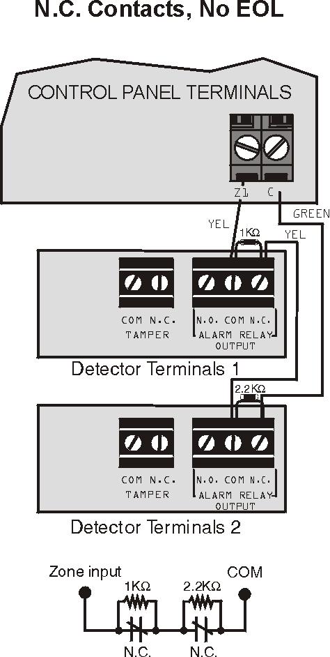
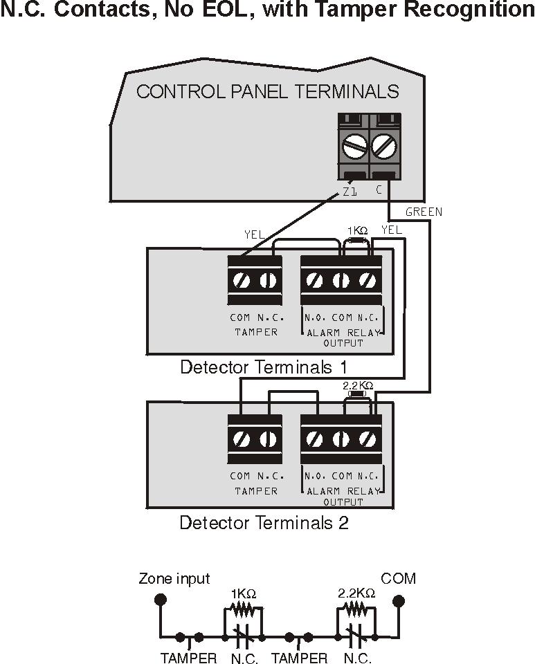
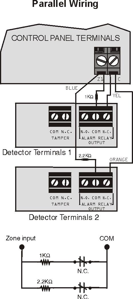
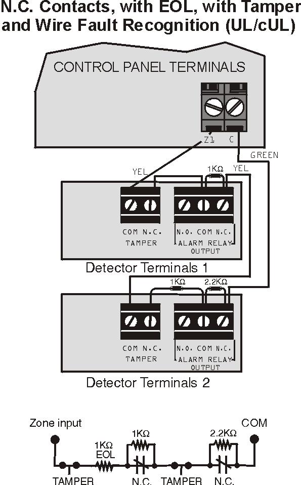
52 Advanced Technology Zone (ATZ) Connections 52 Programming Guide
![Connecting Fire Circuits and PGMs For 4-wire installation: Program the Activation Event so that the smoke detectors can be reset by pressing the [CLEAR] + [ENTER] keys for three seconds.](/docs-images/75/71841682/images/53-2.jpg "See Event Group # 6 on page 18. For 2-wire installation (except SP5500): Press [CLEAR] + [ENTER] to automatically reset smoke.")
53 Connecting Fire Circuits and PGMs For 4-wire installation: Program the Activation Event so that the smoke detectors can be reset by pressing the [CLEAR] + [ENTER] keys for three seconds. See Event Group # 6 on page 18. For 2-wire installation (except SP5500): Press [CLEAR] + [ENTER] to automatically reset smoke. All 4-wire smoke detectors must be connected using the daisy chain configuration. Each control panel (except the SP5500) supports a maximum of five 2-wire smoke detectors. Alarm Relay and PGM Connections Current consumption must not exceed 700mA. PGM1 and PGM2 cannot exceed 150mA or cannot exceed the power supply s current limit. AC Power & Backup Battery Connections Transformer: DC Power Supply rated at: Auxiliary Supply can provide a maximum of: Acceptable Battery Charge Currents (section [700] option [2]) Transformer Requirements Table 16VAC 20VA* (Amseco XP-1620) 16.5VAC 40VA (Universal UB1640W) *not verified by UL MG5000/MG5050 = 1.0A SP5500/SP6000/SP7000 = 1.4A typ: 600mA max: 700mA UL installations: typ. 200mA 350mA/700mA Rechargeable Battery UL/ULC - 12Vdc / 4Ah or 7Ah Partial view of control panel UL Warning: A 12Vdc / 7Ah battery is required to comply with UL fire requirements. Caution: Disconnect battery before replacing the fuse. Improper connection of the transformer may result in damage to the system. Magellan / Spectra SP 53
54 Connecting to WinLoad Computer containing WinLoad software Standard DB-9 cable (9-pin serial cable) 306 Adapter/ CONV4USB Converter 4-pin connector cable Serial Connector Updating Firmware Using WinLoad To update your system firmware: 1. Connect the product to your computer using a 307USB Direct Connect Interface or CONV4USB Converter. 2. Start WinLoad Installer Upload/Download Software. 3. Click the In-field Programmer button. 4. Verify the product information located in the In-Field Firmware Programmer window. If the firmware programmer does not automatically detect your control panel, click the Com port settings button and select the correct Com port. Then click the Refresh Product Info button to connect with the panel. 5. To check for new updates, click the Download Firmware from the web button. 6. From the Select Firmware drop-down box, select the firmware version you wish to install. or If you have already downloaded the.pef file from paradox.com, click the [...] button and select the location of the.pef file. 7. Click the Update product firmware button. When the download process finishes, the update is complete. 54 Programming Guide
55 Metal Box Installation The crosses and dotted line represent the mounting location. If you need specific dimensions, contact Paradox Distributor Support. For UL recommended installation for the MG5000 only, place the PCB one notch lower than the mounting location. MG5000 (8x10 ) MG5000 (11x11 ) MG5050 (11x11 ) Magellan / Spectra SP 55
56 SP5500 (8x10 ) SP6000 (11x11 ) SP7000 (11x11 ) 56 Programming Guide
57 MG5000 PCB Layout Used for In-Field Firmware upgrade through a 307USB Direct Connect Interface. See Connecting to WinLoad on page 54 for details. EBUS and Dialer: Used with the VDMP3 plug-in voice module for voice reporting. Antennas Press and hold the RESET button for five seconds. The STATUS LED will start flashing. Within 2 seconds of this flashing, press the reset switch again. The panel will reset to default and restart. Four pin connector can be used for quick installation of a keypad. Charge LED: Charging and Battery test LED "STATUS" LED: Flash once every second = Normal Flashes ON 1 second and OFF 1 second = Any trouble Always ON = Panel is using phone line Fast flash 6 seconds after power up = Installer lock enabled "RX" & TX LED: Flashes quickly when receiving or transmitting RF signals from wireless devices. Do not cut, bend or alter the antennas and ensure that electrical wires do not cross over the antennae, as this may affect signal reception. Paradox Memory Key (PMC-4 PMC-5) Disconnect telephone line before servicing. Refer to AC Power & Backup Battery Connections on page 53. The "BELL" output will shutdown if the current exceeds 3A. Connection for Self-Contained Bell/Siren The sum of the current drawn from the BELL and AUX must be limited to 1.3A (40VA transformer strongly recommended). Exceeding this limit will overload the panel power supply and lead to complete system shutdown. Refer to Single Zone Inputs on page 51 To provide maximum lightning protection we strongly recommend having separate earth connections for the dialer and zone ground terminals. AWG#14 single conductor solid copper wire To metallic enclosure Max. amount of keypads = 15 keypads Max. current = 700 ma Max. distance of keypad from panel = 76m (250 feet) Max. total run of wire = 230m (750 feet) Cold water pipe grounding Ground clamp AUX Power Refer to transformer requirements on page 53 for Aux. Power Output. To connect additional wiring to auxiliary power, use the red (+) and black (-) keypad connectors. Auxiliary power will shut down if current exceeds 1.1A. If the auxiliary output is overloaded and is shut down, you must disconnect all loads from the output for at least 10 seconds before reconnecting any load back to the auxiliary output. This equipment must be installed and maintained by qualified service personnel only. For UL and C-UL warnings, refer to the UL and C-UL Warnings section at the back of the Reference & Installation Manual. * If EOL is enabled: see section [706] option [2]. For the keypad s zone configurations, refer to Installer Quick Menu on page 3. Also refer to keypad zone connections on page 51. For the keypad s zone configurations, refer to the Installer Quick Menu. If EOL is enabled: see section [706] option [2]. Also refer to Keypad Zone Connections on page 51. Magellan / Spectra SP 57

58 MG5050 PCB Layout LEDs Charge LED: Charging and battery test LED Status LED: Flash once every second = Normal Flashes ON 1 second and OFF 1 second = Any trouble Always ON = Panel is using phone line Fast flash 6 seconds after power up = Installer lock enabled "RX" & TX LED: Flashes quickly when receiving or transmitting RF signals from wireless devices. Paradox Memory Key (PMC-4, PMC-5) Do not cut, bend or alter the antennas and ensure that electrical wires do not cross over the antennae, as this may affect signal reception. EBUS and Dialer: Used with the VDMP3 plug-in voice module for voice reporting. Used for In-Field Firmware upgrade through a 307USB Direct Connect Interface. See Connecting to WinLoad on page 54 for details. Antennas Press and hold the RESET button for five seconds. The STATUS LED will start flashing. Within 2 seconds of this flashing, press the reset switch again. The panel will reset to default and restart. Four pin connector can be used for quick installation of a keypad. Disconnect telephone line before servicing. Refer to AC Power & Backup Battery Connections on page 53. The "BELL" output will shutdown if the current exceeds 3A. Connection for Self-Contained Bell/Siren The sum of the current drawn from the BELL and AUX must be limited to 1.3A (40VA transformer strongly recommended). Exceeding this limit will overload the panel power supply and lead to complete system shutdown. Refer to Single Zone Inputs on page 51 To provide maximum lightning protection we strongly recommend having separate earth connections for the dialer and zone ground terminals. AWG#14 single conductor solid copper wire To metallic enclosure Max. amount of keypads = 15 keypads Max. current = 700 ma Max. distance of keypad from panel = 76m (250 feet) Max. total run of wire = 230m (750 feet) Cold water pipe grounding Ground clamp AUX Power Refer to transformer requirements on page 53 for Aux. Power Output. To connect additional wiring to auxiliary power, use the red (+) and black (-) keypad connectors. Auxiliary power will shut down if current exceeds 1.1A. If the auxiliary output is overloaded and is shut down, you must disconnect all loads from the output for at least 10 seconds before reconnecting any load back to the auxiliary output. This equipment must be installed and maintained by qualified service personnel only. For UL and C-UL warnings, refer to the UL and C-UL Warnings section at the back of the Reference & Installation Manual. * If EOL is enabled: see section [706] option [2]. For the keypad s zone configurations, refer to Installer Quick Menu on page 3. Also refer to keypad zone connections on page 51. * For the keypad s zone configurations, refer to the Installer Quick Menu. If EOL is enabled: see section [706] option [2]. Also refer to Keypad Zone Connections on page Programming Guide
59 SP5500 PCB Layout Charge LED: Charging and battery test LED LEDs Status LED: Flash once every second = Normal Flashes ON 1 second and OFF 1 second = Any trouble Always ON = Panel is using phone line Fast flash 6 seconds after power up = Installer lock enabled Used for In-Field Firmware upgrade through a 307USB Direct Connect Interface. See Connecting to WinLoad on page 54 for details. Four pin connector can be used for quick installation of a keypad. PGM +/- Trigger not supported by SP5500 EBUS and Dialer: Used with the VDMP3 plug-in voice module for voice reporting. Paradox Memory Key (PMC-4, PMC-5) Refer to AC Power & Backup Battery Connections on page 53. Press and hold the RESET button for five seconds. The STATUS LED will start flashing. Within 2 seconds of this flashing, press the reset switch again. The panel will reset to default and restart. Disconnect telephone line before servicing. The "BELL" output will shutdown if the current exceeds 3A. Refer to Single Zone Inputs on page 51 AWG#14 single conductor solid copper wire Cold water pipe grounding AUX Power Refer to transformer requirements on page 53 for Aux. Power Output. To connect additional wiring to auxiliary power, use the red (+) and black (-) keypad connectors. Auxiliary power will shut down if current exceeds 1.1A. If the auxiliary output is overloaded and is shut down, you must disconnect all loads from the output for at least 10 seconds before reconnecting any load back to the auxiliary output. To provide maximum lightning protection we strongly recommend having separate earth connections for the dialer and zone ground terminals. Max. amount of keypads = 15 keypads Max. current = 700 ma Max. distance of keypad from panel = 76m (250 feet) Max. total run of wire = 230m (750 feet) To metallic enclosure Ground clamp Connection for Self-Contained Bell/Siren * If EOL is enabled: see section [706] option [2]. For the keypad s zone configurations, refer to Installer Quick Menu on page 3. Also refer to keypad zone connections on page 51. For the keypad s zone configurations, refer to the Installer Quick Menu. If EOL is enabled: see section [706] option [2]. Also refer to Keypad Zone Connections on page 51. The sum of the current drawn from the BELL and AUX must be limited to 1.3A (40VA transformer strongly recommended). Exceeding this limit will overload the panel power supply and lead to complete system shutdown. * This equipment must be installed and maintained by qualified service personnel only. For UL and C-UL warnings, refer to the UL and C-UL Warnings section at the back of the Reference & Installation Manual. Magellan / Spectra SP 59

60 SP6000 PCB Layout Charge LED: Charging and battery test LED LEDs Status LED: Flash once every second = Normal Flashes ON 1 second and OFF 1 second = Any trouble Always ON = Panel is using phone line Fast flash 6 seconds after power up = Installer lock enabled Used for In-Field Firmware upgrade through a 307USB Direct Connect Interface. See Connecting to WinLoad on page 54 for details. Four pin connector can be used for quick installation of a keypad. PGM Trigger: This jumper allows you to choose whether the solid state relay PGMs are grounded (-), or give out 12V (+). Refer to AC Power & Backup Battery Connections on page 53. EBUS and Dialer: Used with the VDMP3 plug-in voice module for voice reporting. Press and hold the RESET button for five seconds. The STATUS LED will start flashing. Within 2 seconds of this flashing, press the reset switch again. The panel will reset to default and restart. Paradox Memory Key (PMC-4, PMC-5) Disconnect telephone line before servicing. The "BELL" output will shutdown if the current exceeds 3A. Refer to Single Zone Inputs on page 51 AWG#14 single conductor solid copper wire Cold water pipe grounding AUX Power Refer to transformer requirements on page 53 for Aux. Power Output. To connect additional wiring to auxiliary power, use the red (+) and black (-) keypad connectors. Auxiliary power will shut down if current exceeds 1.1A. If the auxiliary output is overloaded and is shut down, you must disconnect all loads from the output for at least 10 seconds before reconnecting any load back to the auxiliary output. To provide maximum lightning protection we strongly recommend having separate earth connections for the dialer and zone ground terminals. To metallic enclosure Max. amount of keypads = 15 keypads Max. current = 700 ma Max. distance of keypad from panel = 76m (250 feet) Max. total run of wire = 230m (750 feet) Ground clamp Connection for Self-Contained Bell/Siren The sum of the current drawn from the BELL and AUX must be limited to 1.3A (40VA transformer strongly recommended). Exceeding this limit will overload the panel power supply and lead to complete system shutdown. When using an SP6000 panel in conjunction with an MG-RTX3, all MG32LED and MG10LEDV/H keypads must be versions 2.0 or higher. * If EOL is enabled: see section [706] option [2]. For the keypad s zone configurations, refer to Installer Quick Menu on page 3. Also refer to keypad zone connections on page 51. * For the keypad s zone configurations, refer to the Installer Quick Menu. If EOL is enabled: see section [706] option [2]. Also refer to Keypad Zone Connections on page 51. This equipment must be installed and maintained by qualified service personnel only. For UL and C-UL warnings, refer to the UL and C-UL Warnings section at the back of the Reference & Installation Manual. 60 Programming Guide
All-In-One Wireless Security System V3.2 Programming Guide. Model # MG6130 / MG6160
 All-In-One Wireless Security System V3.2 Programming Guide Model # MG6130 / MG6160 We hope this product performs to your complete satisfaction. Should you have any questions or comments, please visit www.paradox.com
MG Partition 64-Zone Wireless Console with GPRS/GSM Version 1.6. Section Programming Guide
 MG6250 2-Partition 64-Zone Wireless Console with GPRS/GSM Version.6 Section Programming Guide Things You Need to Know About this Programming Guide The MG6250 All-in-one Wireless Console can be programmed
PROGRAMMING GUIDE SPECTRA CONTROL PANELS V , 1725EX, 1728 AND 1728EX 1755, 1755EX, 1758, AND 1758EX
 PROGRAMMING GUIDE SPECTRA CONTROL PANELS V1.2 1725, 1725EX, 1728 AND 1728EX 1755, 1755EX, 1758, AND 1758EX TABLE OF CONTENTS HOW DO I PROGRAM THE SYSTEM?... 4 Single Digit Data Entry Method (Hexadecimal
Digiplex System V2.14 / V2.2ACC. Control Panel Programming Guide
 Digiplex System V2.14 / V2.2ACC Control Panel Programming Guide Table of Contents Getting Started...2 What Do I Do First?...2 How Do I Program the Control Panel?...2 Single Digit Entry Method...2 Multiple
8-zone Expansion Module
 8-zone Expansion Module APR3-ZX8 SECTION [001] : General Options Option OFF ON [1] Tamper Recognition ON = Input 8 (Z8) becomes tamper input = Default setting Disabled Enabled [2] PGM Deactivation After
MG5000 MG5050 SP5500 SP6000 SP7000. User Guide
 MG5000 MG5050 SP5500 SP6000 SP7000 User Guide We hope this product performs to your complete satisfaction. Should you have any questions or comments, please visit www.paradox.com and send us your comments.
1728EX, 1728, 1738EX AND 1738 SYSTEM PROGRAMMING GUIDE
 DEFAULT INSTALLER CODE 0000 / 000000 (see section [281] on page 17) DEFAULT SYSTEM MASTER CODE 1234 / 123456 (see section [301] on page 17) HOW DO I ENTER PROGRAMMING MODE? STEP 1: Press [ENTE R] STEP
4-PGM Expansion Module
 4-PGM Expansion Module APR3-PGM4 = Default setting SECTION [001] : General Options SECTION [002] : PGM Options Option OFF ON Option OFF ON [1] Future Use N/A N/A [1] PGM1 Deactivation After Deactivation
Table of Contents. All-In-One Wireless Security System V1.3. Programming Guide. Model # MG-6060 / MG-6030
 All-In-One Wireless Security System V1.3 Programming Guide Model # MG-6060 / MG-6030 Table of Contents Things You Should Know... 2 About This Programming Guide... 2 Conventions... 2 Installer Code (Default:
User Guide MG5000 MG5050 SP5500 SP6000 SP7000
 MG5000 MG5050 SP5500 SP6000 SP7000 User Guide We hope this product performs to your complete satisfaction. Should you have any questions or comments, please visit www.paradox.com and send us your comments.
All-In-One Wireless Security System V1.0. Model #: MG-6060
 All-In-One Wireless Security System V1.0 Model #: MG-6060 Reference and Installation Manual DRAFT Table of Contents Introduction... 5 About Magellan and this Manual... 5 Conventions... 5 Specifications...
All-In-One Wireless Security System V1.0. Model #: MG Reference and Installation Manual
 All-In-One Wireless Security System V1.0 Model #: MG-6060 Reference and Installation Manual Table of Contents Introduction... 3 About Magellan and this Manual... 3 Conventions... 3 Specifications... 3
All-In-One Wireless Security System V1.0. Model # MG Programming Guide
 All-In-One Wireless Security System V1.0 Model # MG-6060 Programming Guide Things You Should Know... 4 About This Programming Guide... 4 Conventions... 4 Installer Code (Default: 0000 / 000000)... 4 Maintenance
HEXA PROGRAMMING: STREAMLINED SECTION PROGRAMMING
 -961212-0004 SOFTWARE VERSION 3.10 CONTROL PANEL RESET: Installer lock must be unlocked. ( 058: enter any value other than 147) Power down reset (1) Remove battery and AC to power down the unit. (2) Connect
HEXA PROGRAMMING: STREAMLINED SECTION PROGRAMMING
 48ESEP-01 SOFTWARE VERSION 3.10 CONTROL PANEL RESET: Installer lock must be unlocked. (Address 058: enter any value other than 147) Power down reset (1) Remove battery and AC to power down the unit. (2)
32-Zone Wireless Transceiver Control Panel MG5000. User s Guide
 32-Zone Wireless Transceiver Control Panel MG5000 MG32LED MG32LRF MG10LEDH MG10LEDV User s Guide We hope this product performs to your complete satisfaction. Should you have any questions or comments,
SOFTWARE VERSION 2.20 CONTROL PANEL RESET: Installer lock must be unlocked. (Address 255: enter any value other than 147)
") -961112-0003 SOFTWARE VERSI 2.20 CTROL PANEL RESET: Installer lock must be unlocked. ( 255: enter any value other than 147) Power down reset (1) Remove battery and AC to power down the unit. (4) Wait 3
-961112-0003 SOFTWARE VERSI 2.20 CTROL PANEL RESET: Installer lock must be unlocked. ( 255: enter any value other than 147) Power down reset (1) Remove battery and AC to power down the unit. (4) Wait 3
CHEAT SHEET: SPECTRA V2.1
 CHEAT SHEET: SPECTRA V2.1 Zone mapping Device connected To which input? NO ATZ WITH ATZ CONTROL PANEL INPUT 1= ZONE 1 ZONE 1 & 6 INPUT 2= ZONE 2 ZONE 2 & 7 INPUT 3= ZONE 3 ZONE 3 & 8 INPUT 4= ZONE 4 ZONE
MG5000 MG5050 SP65 SP4000 SP5500 SP6000 SP7000. User Guide. Always Armed, Never Disarmed. Downloaded from manuals search engine
 MG5000 MG5050 SP65 SP4000 SP5500 SP6000 SP7000 Always Armed, Never Disarmed User Guide Warranty For complete warranty information on this product please refer to the Limited Warranty Statement found on
System Programming Guide
 & System Programming Guide Software Versions 4.4 (728ULT) and 4.1 (738ULT) Installer Code (Default - 728 Ultra: 282828; 738 Ultra: 383838) Full access to programming, except user access codes (PINs). No
SOFTWARE VERSION 2.20 CONTROL PANEL RESET:
 -961112-0002 SOFTWARE VERSI 2.20 CTROL PANEL RESET: Installer lock must be unlocked. ( 255: enter any value other than 147) Power down reset (1) Remove battery and AC to power down the unit. (4) Wait 3
EVO192 v3.0 Fire and Burglary What s New
 EVO192 v3.0 Fire and Burglary What s New Compatibility: EVO192 v3.0 TM50 v1.31 K641 v2.41 Overview: CP-01 Compliancy Wiring Diagram The following sections/options have been added to the EVO192 panel. They
HEXA PROGRAMMING: STREAMLINED SECTION PROGRAMMING
 -961212-0004 SOFTWARE VERSI 3.10 CTROL PANEL RESET: Installer lock must be unlocked. (Address 058: enter any value other than 147) Power down reset (1) Remove battery and AC to power down the unit. (2)
Digiplex Control Panel (DGP-848) - V4.0
 - V4.0") Digiplex Control Panel (DGP-848) - V4.0 DGP-848 Reference and Installation Manual TABLE OF CONTENTS INTRODUCTION... 4 1.0 1.1 Features... 4 1.2 Specifications... 4 INSTALLATION... 5 2.0 2.1 Location &
Digiplex Control Panel (DGP-848) - V4.0 DGP-848 Reference and Installation Manual TABLE OF CONTENTS INTRODUCTION... 4 1.0 1.1 Features... 4 1.2 Specifications... 4 INSTALLATION... 5 2.0 2.1 Location &
IDS X-Series Installer Manual H Issued July 2013
 1 2 Contents 1. Keypads... 5 2. Introduction to the IDS X-Series... 9 Features of the IDS X-Series... 9 3. Installation and Wiring... 10 Installation Requirements... 11 End-of-Line Resistors... 11 Box
LCD and 16-Zone LED Keypads. User s Manual
 LCD and 16-Zone LED Keypads 1689 1641 16-Zone LED Keypad LCD Keypad User s Manual TABLE OF CONTENTS 1.0 INTRODUCTION...3 2.0 BASIC OPERATION...4 2.1 Keypad Indicator Lights... 4 2.2 Visual Feedback...
Always Armed, Never Disarmed User Guide
 32-Zone Security System Always Armed, Never Disarmed User Guide User Settings For security reasons, write only the user s name and not their user code. 4-Digit Codes 6-Digit Codes User # and Name Byp*
Alarm Control Panel WIC-16Z4P WIC-5Z2P. Installation & Operation User Manual
 WIC-16Z4P WIC-5Z2P Installation & Operation User Manual Page : 1/34 INDEX # Function Page 1 Abort Current Communication and Clear Reporting Queue (*59) 13 2 Abort Current Communications (*59) 10 3 Account
SPECTRA 1728, 1738 CHEAT SHEET:
 SPECTRA 1728, 1738 CHEAT SHEET: ZONE MAPPING: Device connected To which input? NO ATZ WITH ATZ CONTROL PANEL INPUT 1= ZONE 1 ZONE 1 & 6 INPUT 2= ZONE 2 ZONE 2 & 7 INPUT 3= ZONE 3 ZONE 3 & 8 INPUT 4= ZONE
Digiplex LED Keypads User s Manual
 KLEDEU03.fm Page -1 Friday, May 4, 2001 11:25 AM Digiplex LED Keypads User s Manual KLEDEU03.fm Page 0 Friday, May 4, 2001 11:25 AM KLEDEU03.fm Page 1 Friday, May 4, 2001 11:25 AM TABLE OF CONTENTS 1.0
TABLE OF CONTENTS TABLE OF CONTENTS 1
 TABLE OF CONTENTS TABLE OF CONTENTS 1 FEATURES 2 Keypad Programmable... 2 EEPROM Memory... 2 Static/Lightning Protection... 2 Supervision... 2 Operation... 2 SPECIFICATIONS 2 PC1550 Control Panel... 2
3 User s settings. 3.3 Internal clock setting
 2.9 Subsystem arming In a large building a sub control panel can be enrolled to the JA-63. The subsystem reports all alarms and failures to the main system. The installer can program if the systems will
This unique feature seamlessly integrates security into your everyday life to give you safe, simple living with peace of mind.
 StayD simplifies your life and makes it safer by protecting you 24 hours a day, 7 days a week without ever having to disarm the system even when entering an armed area. StayD lives with you and protects
Programming Worksheets
 WARNING This manual contains information on limitations regarding product use and function and information on the limitations as to liability of the manufacturer. The entire manual should be carefully
0$(6752 0$(6752. Programming Guide. 6 and 10 Zone Alarm Control Panel ,1752'8&7,21 +(;$ 352*5$00,1* 675($0/,1(' 6(&7,21 352*5$00,1* FIGURE 1 FIGURE 2
 0$(6752 0$(6752 6 and 10 Zone Alarm Control Panel Programming Guide,1752'8&7,21 The Maestro-600 and Maestro-1000 alarm control panels enable reduced number of programming steps. End-users can access most
Version 1.03 January-2002 USER S MANUAL
 Version 1.03 January-2002 1 USER S MANUAL 2 Version 1.03 January-2002 System Details CUSTOMER:...... PHONE:... FAX:... INSTALLED BY:...... PHONE:... FAX:... MAINTENANCE & SERVICE:...... PHONE:... FAX:...
EVOHD. User Guide. Revision 1.1.
 EVOHD User Guide Revision 1.1 www.paradox.com Warranty For complete warranty information on this product please refer to the Limited Warranty Statement found on the website www.paradox.com/terms. Your
Alarm Control Panel WIC-16Z4P WIC-5Z2P. User Instructions
 WIC-16Z4P WIC-5Z2P User Instructions Page : 2/14 INDEX # Function Page 1 Add a New User Code 11 2 Arm or Disarm All Areas or Disarm Selected Areas (Partitioned System) 8 3 Arming the System (Away Mode)
System Introduction. 1.1 Specifications
 System Introduction S E C T I O N 1 1.1 Specifications Downloading Software Support PC585 uses DLS-1 v6.5 and up. Flexible Zone Configuration Four fully programmable zones; system expandable to eight zones
10-Zone Spectra LED Keypads
 10-Zone Spectra LED Keypads User s Guide TABLE OF CONTENTS Introduction... 5 Basic Operation... 6 Auditory Feedback... 6 Keypad Indicator Lights... 8 Zone Display... 8 Alarm Memory Display... 8 Trouble
X64 Wireless Training
 X64 Wireless Training IDS Contents 1 Contents Features 3 Wireless Hardware 4 IDS & Duevi integration PCB 5 LED operation 5 Wireless Device Hardware setup 6 Location 260 7 LED Keypad Instructions 7 Adding
AXI LED USER MANUAL (REV. 1.0)
") Security & Home Automation System AXI LED USER MANUAL (REV. 1.0) CONTENTS PREFACE FEATURES LED KEYPAD OUTLOOK 1.0 LIGHT INDICATION 1 2 4 6 CHAPTER 1: ALARM SYSTEM CONTROL 1.0 USING LED KEYPAD 1.0.1 ARMING
Security & Home Automation System AXI LED USER MANUAL (REV. 1.0) CONTENTS PREFACE FEATURES LED KEYPAD OUTLOOK 1.0 LIGHT INDICATION 1 2 4 6 CHAPTER 1: ALARM SYSTEM CONTROL 1.0 USING LED KEYPAD 1.0.1 ARMING
TABLE OF CONTENTS. FOR THE RECORD 15 PROGRAMMING WORK SHEETS 16 CONTROL PANEL WIRING DIAGRAM inside back cover
 TABLE OF CONTENTS FEATURES 2 SPECIFICATIONS 2 INSTALLATION 3 Mounting the Panel... 3 Mounting the Keypad... 3 Auxiliary Power Connection... 3 PGM Terminal Connections... 3 Bell/Siren Connection... 3 Keypad
User s Guide. SUB-MA7240O-0001.OG.Solution doc. Created: 6/05/03. Last Updated: 23/09/03. MA7240AO-0001 Version 1.0
 User s Guide SUB-MA7240O-0001.OG.Solution40-111.doc Created: 6/05/03 Last Updated: 23/09/03 MA7240AO-0001 Version 1.0 2 Table Of Contents User List...6 Quick Reference..7 Features...7 Keypad User's Guide...8
CC488. Quick Reference Guide Solution Ultima 880
 CC488 EN Quick Reference Guide Solution Ultima 880 CC488 Quick Reference Guide Notices EN 2 Copyright Notice Unless otherwise indicated, this publication is the copyright of Bosch Security Systems Pty
Property of Monitronics Inc
 Enter Program Program Location 1. Hold 8 key for 3 seconds, keypad will beep 2. Enter 4 5 6 7 8 9, display should show dash on display 1. Press [B/A] key display will show 3 dashs 2. Enter 3-digit location
JA-63 Profi User manual
 JA-63 Profi User manual Contents: 1 Limited warranty... 2 2 Indicators... 3 3 Controlling the system... 4 3.1 Arming... 5 3.2 Disarming... 6 3.3 Panic Alarm... 6 3.4 To stop ALARM... 6 3.5 Home arming...
Training Manual Multi-Language with Wireless
 Training Manual Multi-Language with Wireless Installer Training Firmware Version 2.3 X16 Stock Code: 860-1-473-X16 X64 Stock Code: 860-1-864-XS 2 Contents IDS X Series Training V2.3 Contents Contents 3
2000 Series. Program Entry Guide. Control Panels
 2000 Series EN Program Entry Guide Control Panels 2000 Series Program Entry Guide About This Manual EN 2 About This Manual This guide describes the programming parameters available to the 2000 Series Control
CC408. Quick Reference Guide Solution 880
 CC408 EN Quick Reference Guide Solution 880 CC408 Quick Reference Guide Notices EN 2 Copyright Notice Unless otherwise indicated, this publication is the copyright of Bosch Security Systems Pty Ltd ( Bosch
Honeywell Control Panels FOR RESIDENTIAL AND COMMERCIAL INSTALLATIONS. Feature Charts
 Honeywell Control Panels FOR RESIDENTIAL AND COMMERCIAL INSTALLATIONS Feature Charts Control Panels FEATURE CHART LYNX Plus (L3000) (Supported Feature) (Not Supported) N/A (Not Applicable) LYNX Touch (L5210)
Digiplex LED Keypads. User s Manual
 Digiplex LED Keypads User s Manual TABLE OF CONTENTS INTRODUCTION... 6 1.1 Legend...6 BASIC OPERATION... 7 2.1 Auditory Feedback (Beep Tones)...8 2.2 Keypad Indicator Lights...8 2.3 LED Keypads...8 2.4
First Alert 1200C Installer Notes M. Leuck
 First Alert 2C Installer Notes M. Leuck. Programming can done by standard keypads 2. Enter programming with Installer Code + 8 + + 3. Another method of entering programming: Power system down, then back
DL100 DOWNLOADABLE CONTROL COMMUNICATOR INSTALLATION MANUAL
 DL100 DOWNLOADABLE CONTROL COMMUNICATOR INSTALLATION MANUAL TABLE OF CONTENTS 1. GENERAL DESCRIPTION...P.2 2. STANDARD AND OPTIONAL PARTS LIST...P.2 3. FEATURE DEFINITIONS...P.3 4. TERMINAL DRAWING AND
System Introduction. 1.1 PC5015 Specifications S E C T I O N 1
 1.1 PC5015 Specifications System Introduction S E C T I O N 1 Flexible Zone Configuration: 8 Fully Programmable Zones 38 Access Codes: 32 User, 1 System Master, 2 Partition Master, 2 Duress and 1 maintenance
&RPPHUFLDO)LUHDQG%XUJODU\ 3DUWLWLRQHG6HFXULW\6\VWHP ZLWK6FKHGXOLQJ
LUHDQG%XUJODU\ 3DUWLWLRQHG6HFXULW\6\VWHP ZLWK6FKHGXOLQJ") 9,67$)% &RPPHUFLDO)LUHDQG%XUJODU\ 3DUWLWLRQHG6HFXULW\6\VWHP ZLWK6FKHGXOLQJ 8VHU*XLGH FIRE FIRE * PULL K3522 3/99 TABLE OF CONTENTS SYSTEM OVERVIEW...4 General...4 A Partitioned System...4 Zones...5 Fire
9,67$)% &RPPHUFLDO)LUHDQG%XUJODU\ 3DUWLWLRQHG6HFXULW\6\VWHP ZLWK6FKHGXOLQJ 8VHU*XLGH FIRE FIRE * PULL K3522 3/99 TABLE OF CONTENTS SYSTEM OVERVIEW...4 General...4 A Partitioned System...4 Zones...5 Fire
INSTALLATION MANUAL PC15OO
 INSTALLATION MANUAL PC15OO This device complies with Parts 15 and 68 of the FCC rules. Operation is subject to the following two conditions: (1) this device may not cause harmful interference, and (2)
Training Manual with Bi-directional Wireless
 Training Manual with Bi-directional Wireless Installer Training Firmware Version 2.7x X16 Stock Code: 860-1-473-X16 X64 Stock Code: 860-1-864-XS 2 IDS X-Series Training v2.7 Contents Contents 3 X-Series
VISTA-50P VISTA-50PUL
 Security System User's Manual VISTA-50P VISTA-50PUL N5943-6V1 Rev B 4/99 TABLE OF CONTENTS SYSTEM OVERVIEW...4 General...4 A Partitioned System...4 Zones...4 Fire Protection...5 Burglary Protection...5
DSC Power832/PC5010 Wiring the MN01-4G Cellular Communicator and Programming the Panel
 DSC Power832/PC5010 Wiring the MN01-4G Cellular Communicator and Programming the Panel CAUTION: It is advised that an experienced alarm installer programs the panel as further programming may be required
Control/Communicator
 Architectural & Engineering Specifications Control/Communicator 1.0 GENERAL... 2 1.1 SCOPE OF WORK... 2 1.1.1 Introduction... 2 1.2 GENERAL CONDITIONS... 2 1.2.1 After-Sales Support... 2 1.2.2 Quality
SENTROL ZX400/ZX410. Security System Control. Programming
 SENTROL ZX400/ZX410 Security System Control Programming 1 2 TABLE OF CONTENTS Table of Contents Operating the System... 5 Introduction...5 Powering Up With the Control Station...5 Control Stations...6
System Introduction. 1.1 Specifications S E C T I O N 1
 System Introduction S E C T I O N 1 1.1 Specifications Control Panel Specifications Flexible Zone Configuration: 8 Fully Programmable Zones 37 Access Codes: 32 User, 1 System Master, 2 Partition Master
RANGER 7600 DOWNLOADABLE CONTROL COMMUNICATOR INSTALLATION MANUAL
 RANGER 7600 DOWNLOADABLE CONTROL COMMUNICATOR INSTALLATION MANUAL TABLE OF CONTENTS 1. TABLE OF CONTENTS... P.1 2. GENERAL DESCRIPTION... P.2... 3. STANDARD AND OPTIONAL PARTS LIST... P.2... 4. FEATURE
NetworX Series NX-6 CONTROL PANEL. Installation and Startup
 NetworX Series NX-6 CONTROL PANEL Installation and Startup 25 GE Security All rights reserved. These instructions do not purport to cover all details or variations in equipment nor to provide every possible
DSC Power832/PC5010 Wiring the MN01-4G Cellular Communicator and Programming the Panel
 DSC Power832/PC5010 Wiring the MN01-4G Cellular Communicator and Programming the Panel CAUTION: It is advised that an experienced alarm installer programs the panel as further programming may be required
TABLE OF CONTENTS. General Description Standard and Optional Parts List Feature Definitions Comments about the 8600E...
 5$1*(5( DOWNLOADABLE CONTROL COMMUNICATOR INSTALLATION MANUAL TABLE OF CONTENTS General Description... 2 Standard and Optional Parts List... 2 Feature Definitions... 3 Comments about the 8600E... 4 Terminal
Control/Communicator Installation Manual
 DAS NETWORX NX-12 Control/Communicator Installation Manual General Description...2 Ordering Information...2 Option Definitions...3 Programming the LED Code Pads...5 Programming the NX-12...9 Types of Programming
Contents. Glossary
 Contents Glossary ------------------------------------------------------------------------------------------------------ 6 1. Introduction to the IDS 1632 -------------------------------------------------------------
Solution 6+6 Wireless On/Off Installation Manual ISSUE 1.20
 Solution 6+6 Wireless On/Off Installation Manual ISSUE 1.20 MA670I This page has been included for you to cut out and insert into the spine of the folder Solution 6+6 Wireless On/Off Installation Manual
&RPPHUFLDO%XUJODU\ 3DUWLWLRQHG6HFXULW\6\VWHP ZLWK6FKHGXOLQJ
 READY ARMED READY 1 OFF 7 INSTANT READY 2 AWAY 8 CODE 6BYPASS 9 CHIME 9,67$% &RPPHUFLDO%XUJODU\ 3DUWLWLRQHG6HFXULW\6\VWHP ZLWK6FKHGXOLQJ 8VHU*XLGH ARMED READY 1 OFF 2 AWAY 3 STAY 4 MAX 5 TEST 6 BYPASS
RANGER 8980E DOWNLOADABLE CONTROL COMMUNICATOR INSTALLATION MANUAL
 RANGER 8980E DOWNLOADABLE CONTROL COMMUNICATOR INSTALLATION MANUAL TABLE OF CONTENTS GENERAL DESCRIPTION...2 STANDARD AND OPTIONAL PARTS LIST...2 FEATURE DEFINITIONS...3 TERMINAL DRAWING AND SPECIAL NOTES...4
Watchguard WGAP864 User Manual
 Watchguard WGAP864 User Manual v1.0 Issued September 2016 1 2 Table of Contents Glossary... 5 1. Introduction to your Watchguard WGAP864... 6 2. Before Operating your Alarm System... 6 3. Understanding
Testing the System. Battery Test. Dialer Test. Fire Drill Test (Code + [#] + 69) One-Man Fire Walk-Test (Code + [#] + 68)
![Testing the System. Battery Test. Dialer Test. Fire Drill Test (Code + [#] + 69) One-Man Fire Walk-Test (Code + [#] + 68)](/thumbs/79/79864325.jpg "Testing the System. Battery Test. Dialer Test. Fire Drill Test (Code + [#] + 69) One-Man Fire Walk-Test (Code + [#] + 68)") F A 1 7 0 0 c Testing the System Battery Test When AC power is present, the FA1700C runs a brief battery test every 60 seconds to determine if there is a battery connected, and runs an extended battery
F A 1 7 0 0 c Testing the System Battery Test When AC power is present, the FA1700C runs a brief battery test every 60 seconds to determine if there is a battery connected, and runs an extended battery
GLOBAL. InstallatIon & operation manual
 InstallatIon & operation manual INDEX 1. INTRODUCTION... 5 2. FEATURES AND FUNCTIONS 2.1 Reporting Options... 2.2 Interfaces... 2.3 Programming... 2.4 Indicators and Controls...... 6 6 6 6 6 3. INSTALLATION...
Other trade names mentioned in this document may be registered trademarks or trademarks of respective product manufacturers or vendor products.
 Attention! Read this user manual carefully. Representative of the company installing the alarm system will explain which security module SP231 functions needs to be activated to ensure proper security
Engineer Reference. EN :2006+A1:2009 EN :2009 EN :2008 EN :2005+A1:2008 Security Grade 2 Environmental Class II
 EN50131-1:2006+A1:2009 EN50131-3:2009 EN50131-6:2008 EN50131-5-3:2005+A1:2008 Security Grade 2 Environmental Class II Engineer Reference INTERNAL SIREN WARNING The Enforcer 32-WE control panel contains
RANGER 8600 DOWNLOADABLE CONTROL COMMUNICATOR INSTALLATION MANUAL
 RANGER 8600 DOWNLOADABLE CONTROL COMMUNICATOR INSTALLATION MANUAL TABLE OF CONTENTS GENERAL DESCRIPTION... 2 STANDARD AND OPTIONAL PARTS LIST... 2 PARTS DIAGRAM... 3 TERMINAL DRAWING AND SPECIAL NOTES...
**** **** A B ARMED FIRE FIRE C D READY OFF AWAY STAY 2 3 MAXIMUM TEST BYPASS PULL INSTANT CODE CHIME. First Alert READY. * 0 # Professional
 ARMED READY READY )$&&$&% )LUHDQG%XUJODU\ 3DUWLWLRQHG6HFXULW\6\VWHPV ZLWK6FKHGXOLQJ **** **** A B C D FIRE FIRE First Alert OFF AWAY STAY 2 3 1 4 5 6 7 8 9 MAXIMUM TEST BYPASS INSTANT CODE CHIME * 0 #
INSTALLATION MANUAL & PROGRAM RECORD SHEET
 INSTALLATION MANUAL & PROGRAM RECORD SHEET TABLE OF DESCRIPTION CONTENTS PAGE WIRING MANUAL 2-6 MENU CHART 7 INSTALLER FUNCTIONS 8 MENU 1 SYSTEM TIMES 9 MENU 2 ZONE CONFIGURATION 10-14 MENU 3 SYSTEM OPTIONS
NetworX NX-8V2. LED Keypad User Manual
 NetworX NX-8V2 LED Keypad User Manual POWER Light is on when AC power is present; flashes to indicate a low battery condition. ARMED Light is on when armed; off when disarmed; flashes to indicate a previous
Cerber C Zone and 2-Partition Burglary Control Panel for your home and office. Hook-Up & Programming Book[draft] / version 1.
![Cerber C Zone and 2-Partition Burglary Control Panel for your home and office. Hook-Up & Programming Book[draft] / version 1.](/thumbs/94/121988732.jpg "Cerber C Zone and 2-Partition Burglary Control Panel for your home and office. Hook-Up & Programming Book[draft] / version 1.") Cerber C612 12-Zone and 2-Partition Burglary Control Panel f your home and office Hook-Up & Programming Book[draft] 25.10.2006/ version 1.9 B Table of contents 1. INSTALLING AND COMMISSIONING... 5 1.1.
Cerber C612 12-Zone and 2-Partition Burglary Control Panel f your home and office Hook-Up & Programming Book[draft] 25.10.2006/ version 1.9 B Table of contents 1. INSTALLING AND COMMISSIONING... 5 1.1.
User s Information Guide R2A
 Pi HSC505 Home Security Controller User s Information Guide R2A Page 1 of 15 of its development program. 1This document and product are copyrighted and all rights are reserved. Introduction Convention
Installation Manual IMPORTANT. PC5020 Version 3.1 DLS-3 v1.3 and higher
 IMPORTANT WARNING:This manual contains information on limitations regarding product use and function and information on the limitations as to liability of the manufacturer. The entire manual should be
Series. NX-4-EUR Control Panel. Installation manual
 g GE Security NetworX TM Series NX-4-EUR Control Panel Installation manual CONTENTS CONTENTS...2 GENERAL INFORMATION...4 ORDERING INFORMATION...4 FEATURE DEFINITIONS...5 PROGRAMMING THE NX-4 KEYPADS...12
Quick Programmer s Manual
 Version 2.604 (31/03/05) p1 Quick Programmer s Manual 2005. Inner Range Pty. Ltd. Part Number: 630048V2 p2 Version 2.604 (31/03/05) TABLE OF CONTENTS. 1. PROGRAMMING FLOWCHART. The following flowchart
Security System With Scheduling. User Guide. N5943-8V4 7/04 Rev A
 ADEMCO VISTA-120 Security System With Scheduling User Guide N5943-8V4 7/04 Rev A Your Honeywell security system is designed for use with devices manufactured or approved by Honeywell for use with your
Control Panel. 1.0 GENERAL SCOPE OF WORK Introduction... 2
 Architectural & Engineering Specifications Control Panel 1.0 GENERAL... 2 1.1 SCOPE OF WORK... 2 1.1.1 Introduction... 2 1.2 GENERAL CONDITIONS... 2 1.2.1 After-Sales Support... 2 1.2.2 Quality assurance...
System Introduction. Digital Communicator Specifications: Supports all Major Formats including SIA and Contact ID Event Initiated Personal Paging
 1.1 Specifications System Introduction S E C T I O N 1 Control Panel Specifications Flexible Zone Configuration: 8 Fully Programmable Zones 38 Access Codes: 32 User, 1 System Master, 2 Partition Master,
SECURITY SYSTEM 4110DL. Programming Form Programming Form Programming Form 4110DL-PRV3 10/96
 SECURITY SYSTEM 4110DL Programming Form Programming Form Programming Form 4110DL-PRV3 10/96 4110DL PROGRAMMING FORM FIELD FUNCTION [ ] = Default Value SYSTEM OPTIONS (*20-*28) *20 MASTER SECURITY CODE
XT30/XT50 PROGRAMMING PART 2. Slide 1. Slide 2. Slide 3. Objectives. XT30/XT50 Basic Training Programming- Part 2. Bell Options
 Slide 1 XT30/XT50 Basic Training Programming- Part 2 Slide 2 Objectives After completing this course you will: 1) Understand how to prepare the panel for programming and how to access the built-in programmer.
(31/03/05) Version p1. INNER RANGE IQ. Programmer s Manual. Programmer s Manual Inner Range Pty. Ltd. Part Number:
 Version p1. INNER RANGE IQ. Programmer s Manual. Programmer s Manual Inner Range Pty. Ltd. Part Number:") (31/03/05) Version 2.604 p1 Programmer s Manual 2005. Inner Range Pty. Ltd. Part Number: 630047 p2 Version 2.604 (31/03/05) TABLE OF CONTENTS. Programming Methods... 3 1. Introduction 1.1 System Overview...
(31/03/05) Version 2.604 p1 Programmer s Manual 2005. Inner Range Pty. Ltd. Part Number: 630047 p2 Version 2.604 (31/03/05) TABLE OF CONTENTS. Programming Methods... 3 1. Introduction 1.1 System Overview...
Property of Monitronics Inc
 Enter Program Press CODE key + * + 2468 + 1 (also try 2121) Installer Options Move to location Program location Exit Program Default Panel Hex Program Code + * + Installer Code + 1 = Enter Programming
$'(0&2 9,67$ 3DUWLWLRQHG 6HFXULW\ 6\VWHP 8VHU *XLGH N7003V3 5/04 Rev A
 $'(0&29,67$ 3DUWLWLRQHG6HFXULW\6\VWHP 8VHU*XLGH N7003V3 5/04 Rev A 2 TABLE OF CONTENTS SYSTEM OVERVIEW...5 General...5 A Partitioned System...5 Zones...5 Fire Protection...6 Burglary Protection...6 Alarms...6
IDS816 User Manual H Issued January 2009
 1 Contents Glossary-------------------------------------------------------------------------------------------------------------------6 1. Introduction to the IDS 816---------------------------------------------------------------------------7
Fire Burglary Instruments Inc. XL-2G Gold Control/Communicator Installation Training Seminar Rev. 5/96
 Fire Burglary Instruments Inc. XL-2G Gold Control/Communicator Installation Training Seminar Rev. 5/96 XL-2G Gold Product Overview 7 Zones (6 programmable + panic or keyswitch zone) Fast Loop Response
Understanding the Code Pad lights...4. Code Pad tones...5. Fully arming the system On MODE...6. Fully arming the system - Quick Arm MODE...
 TABLE OF CONTENTS...Glossary of terms...2...code Pad Diagram...3 Understanding the Code Pad lights...4 Code Pad tones...5 Fully arming the system On MODE...6 Fully arming the system - Quick Arm MODE...6
636 and 646 Keypads. User s Manual
 636 and 646 Keypads 636 646 User s Manual Table Of Contents Basic Operation... 2 Access Codes... 4 Arming & Disarming... 5 Panic Zones... 11 Key Access Programming... 12 Additional Features... 13 Trouble
IDS S E C U R I T Y IDS816. User Manual. MANUAL NO A ISSUED November 2004 VERSION 1.00
 INHEP DIGITAL IDS S E C U R I T Y IDS816 User Manual MANUAL NO. 700-283-02A ISSUED November 2004 VERSION 1.00 Contents 1. Introduction to the IDS816... 4 2. Understanding the Keypad Indicators... 4 3.
GEM-P800 Programming Instructions
 NOTE After 15 minutes of keypad inactivity the keypad will emit a steady tone indicating the panel has been left in Dealer Program Mode Enter Dealer Code to exit or press the key to return to Dealer Program