Table of Contents. Part I SAFETY MESSAGE TO INSTALLERS OF EMERGENCY WARNING EQUIPMENT 2 Part II Vehicle Operation 4. Part III Safety Messages 13
|
|
|
- Jeffry Norris
- 6 years ago
- Views:
Transcription
1 Manual
2 I SS2000 TouchScreen Installation Guide Table of Contents Foreword 0 Part I SAFETY MESSAGE TO INSTALLERS OF EMERGENCY WARNING EQUIPMENT 2 Part II Vehicle Operation 4 1 Installing the... SS2000 TouchScreen Program 4 2 Vehicle Operation... using SS2000 TouchScreen 5 3 Configuring... the SS2000 TouchScreen Interface 9 4 Opening... an Existing Configuration File 11 5 Saving a... Configuration File 12 6 Testing After... Installation 12 Part III Safety Messages 13 1 SAFETY MESSAGE... TO OPERATORS OF SIRENS AND LIGHT/SOUND 13 2 SAFETY MESSAGE... TO PERSONNEL SERVICING ELECTRONIC SIRENS 14 Index 17
3 SAFETY MESSAGE TO INSTALLERS OF EMERGENCY WARNING EQUIPMENT 2 1 SAFETY MESSAGE TO INSTALLERS OF EMERGENCY WARNING EQUIPMENT WARNING The lives of people depend on your proper installation and servicing of Federal products. It is important to read and follow all instructions shipped with the products. In addition, listed below are some other important safety instructions and precautions you should follow: Before Installation: Qualifications To properly install an electronic siren and lighting system: you must have a good understanding of automotive electrical procedures and systems, along with proficiency in the installation and service of safety warning equipment. Always refer to the vehicle's service manuals when performing equipment installations on a vehicle. Sound Hazards Your hearing and the hearing of others, in or close to your emergency vehicle, could be damaged by loud sounds. This can occur from short exposures to very loud sounds, or from longer exposures to moderately loud sounds. For hearing conservation guidance, refer to federal, state, or local recommendations. OSHA Standard offers guidance on "Permissible Noise Exposure". All effective sirens and horns produce loud sounds (120 db) that may cause permanent hearing loss. Always minimize your exposure to siren sound and wear hearing protection. Do not sound the siren indoors or in enclosed areas where you and others will be exposed to the sound. Federal Signal siren amplifiers and speakers are designed to work together as a system. Combining a siren and speaker from different manufacturers may reduce the warning effectiveness of the siren system and may damage the components. You should verify or test your combination to make sure the system works together properly and meets federal, state and local standards or guidelines. Light Hazards The lighting products you are installing may contain high intensity LED devices. To prevent eye damage, DO NOT stare into the light beam at close range. Glass light bulb and strobe tubes are fragile and can fail. You should frequently inspect the light system to ensure that it is operating properly. Over time, roof mounted lighting systems can loosen. Frequently inspect the lighting system to be sure it is securely fastened to the vehicle. Halogen lamps and strobe tubes can burst. Always wear hand and eye protection when working with halogen lamps or strobe tubes
4 3 SS2000 TouchScreen Installation Guide Strobe light systems use high voltage. Always disconnect power from any strobe lighting device and wait at least 5 minutes before servicing the unit. During Installation: DO NOT get metal shavings inside the product. Metal shavings in the product can cause the system to fail. If drilling must be done near the unit, place an ESD approved cover over the unit to prevent metal shavings from entering the unit. Inspect the unit after mounting to be sure there are no shavings present in or near the unit. DO NOT connect this system to the vehicle battery until ALL other electrical connections are made, mounting of all components is complete, and you have verified that no shorts exist. If wiring is shorted to vehicle frame, high current conductors can cause hazardous sparks resulting in electrical fires or flying molten metal. Be sure the siren amplifier and speaker(s) in your installation have compatible wattage ratings. In order for the electronic siren to function properly, the ground connection must be made to the NEGATIVE battery terminal. Sound output will be severely reduced if any objects are in front of the speaker. If maximum sound output is required for your application, you should ensure that the front of the speaker is clear of any obstructions. Install the speaker(s) as far forward on the vehicle as possible, in a location which provides maximum signaling effectiveness and minimizes the sound reaching the vehicle's occupants. Refer to the National Institute of Justice guide for further information. Mounting the speakers behind the grille will reduce the sound output and warning effectiveness of the siren system. Before mounting speakers behind the grille, make sure the vehicle operators are trained and understand that this type of installation is less effective for warning others. Sound propagation and warning effectiveness will be severely reduced if the speaker is not facing forward. Carefully follow the installation instructions and always install the speaker with the projector facing forward. DO NOT install the speaker(s ) or route the speaker wires where they may interfere with the operation of air bag sensors. Installation of two speakers requires wiring speakers in phase. Never attempt to install aftermarket equipment, which connects to the vehicle wiring, without reviewing a vehicle wiring diagram - available from the vehicle manufacturer. Insure that your installation will not affect vehicle operation and safety functions or circuits. Always check vehicle for proper operation after installation. DO NOT install equipment or route wiring or cord in the deployment path of an air bag. Locate the control heads/computer so the vehicle, controls, and microphone can be operated safely.
5 SAFETY MESSAGE TO INSTALLERS OF EMERGENCY WARNING EQUIPMENT 4 When drilling into a vehicle structure, be sure that both sides of the surface are clear of anything that could be damaged. A light system is a high current device. In order for it to function properly, a separate ground connection must be made. If practical, it should be connected to the negative battery terminal. At a minimum, it may be attached to a solid metal body or chassis part that will provide an effective ground path as long as the light system is to be used. After Installation: After installation, test the siren system and light system to ensure that it is operating properly. Test all vehicle functions, including horn operation, vehicle safety functions and vehicle light systems, to ensure proper operation. Ensure that installation has not affected vehicle operation or changed any vehicle safety function or circuit. After testing is complete, provide a copy of these instructions to the instructional staff and all operating personnel. File these instructions in a safe place and refer to them when maintaining and/or reinstalling the product. Failure to follow all safety precautions and instructions may result in property damage, serious injury, or death to you or others. 2 Vehicle Operation 2.1 Installing the SS2000 TouchScreen Program This chapter outlines the procedure for installing the SS2000 TouchScreen operator software on your PC. If you have already installed the software, proceed to the next section Vehicle Operation using SS2000 TouchScreen. Before You Begin: You will need a copy of the SS2000 TouchScreen Configuration CD from which to load the application. The SS2000 TouchScreen operator application is supported on PC's meeting the following minimum requirements: The table below shows memory requirements for the various versions of Microsoft Windows systems. These are based on Microsoft's minimum recommendations - in some cases more memory is recommended for effective operation of the SS2000 TouchScreen software. Supported Operating System Minimum Memory requirements (MB) Windows (128 recommended) Windows ME 64 (128 recommended) Windows NT 4.x 128 Windows

6 5 SS2000 TouchScreen Installation Guide Required disk space for installation of the application is estimated at 15 MB. Systems should have a minimum of a 450 MHz Pentium processor. Installing the Software: Follow these steps to install SS2000 TouchScreen Interface software on your PC: 1. Insert the SS2000 TouchScreen Interface software CD into your CD-ROM drive. 2. The SS2000 TouchScreen Interface software CD will automatically* launch the installation screen. 3. Click the next button on the screen and follow the instructions that will step you through the rest of the installation process. *Note: If autorun is disabled, or if autorun fails to initiate, browse your computer's hard drive by double-clicking on My Computer icon and browsing the CD ROM drive. Doubleclick on setup.exe to install the SS2000 TouchScreen Interface software. 2.2 Vehicle Operation using SS2000 TouchScreen Before You Begin: A SS2000 TouchScreen Interface software must be installed on the vehicle's computer.
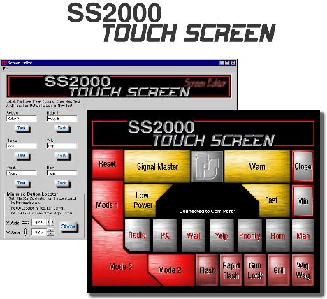
7 Vehicle Operation 6 Connecting the SS2000 TouchScreen Interface Converter Box: The connection from the computer to the SS2000 TouchScreen Converter box has to be established. Provided in the Installation is a Serial cable or a USB to Serial cable kit (CP Tech USB PDA/Serial Adapter) that will provide the connection needed for communication to the SS2000 TouchScreen system. In the USB to Serial cable kit is a separate instruction sheet for installing the drivers needed for proper configuration. Connect the 9-pin serial connector or a USB to Serial cable to the serial port on the back of your computer to the 9-pin serial connector on the Converter box. With the kit supplied RJ11 telephone cable, connect the Control Head to the other RJ11 connector on the Converter box labeled Controlled Head. (See Below for connection) Running the SS2000 TouchScreen Interface Software: After the serial connection has been established, start the SS2000 TouchScreen Interface software by double clicking on the desktop icon. When the software starts you will see the screen below which is the default interface configuration for the software.

8 7 SS2000 TouchScreen Installation Guide The default controls are listed below, but can be altered using the Screen Editor explained in the Configuring the SS2000 TouchScreen Interface section. The controls vary in the amount they can be configured where configurable parameters are the text that is displayed on the button and whether the button acts as a Push On/Push Off toggle switch or a Momentary activation of the feature, which is controlled through the SS2000 Siren. Push On/Push Off buttons act just like a normal switch, push it once and the feature is activated, push it again and the feature is deactivated. Momentary buttons activate the feature for a brief interval and then it is deactivated. As mentioned, this is configurable for some buttons and others are permanently configured one way or the other. Relay Buttons As shown: A, B, C, D, E The relay buttons can be configured for Push On/Push Off or Momentary depending on the SS2000 Siren configuration. The default is Push On/Push Off. The text for these buttons can be edited. Siren Controls As shown: Radio, Pa, Wail, Yelp, Priority, Horn and Man The text for these buttons can be edited. Pursuit Mode Controls
9 Vehicle Operation 8 As shown: Mode 1, Mode 2, and Mode 3 Mode 1, Mode 2 and Mode 3 are always Push On/Push Off. The text of these buttons can be edited. Warning Controls As shown: SignalMaster, Warn, Low Power and Fast Step through pattern controls. Visible representation of SignalMaster controls. The text of these buttons is not editable. Screen Controls As shown: Reset, Min and Close The text of these buttons is not editable. Standard Factory Software: Activation Reset Mode 3 Mode 2 Mode 1 Signal Master Warn Low Power Fast Man Air Horn Wail Response Clears all siren functions. Activates Relay A, Relay B,Relay C, Warn 3 SignalMaster, the Horn Ring Transfer Relay, and enables the Siren.(Configurable Button) Activates Relay A, Relay B, Warn 2 SignalMaster and the Horn Ring Transfer Relay.(Configurable Button) Activates Relay A and Warn 1 SignalMaster.(Configurable Button) Signalmaster Arrow step through (Left Arrow, Right Arrow, Center Out and Off) Signalmaster Warn step through (Warn 1, 2, 3, 4 and Off) Button enables once a SignalMaster pattern is active and allows any pattern to be put into low power mode. Button enables once a SignalMaster pattern is active and changes the sweep speed of all patterns to a faster rate. Will produce peak & hold tone when no other sirens are active. If wail or yelp are active, the tone will change to priority for 8-seconds the revert back to the previous tone. Horn Ring will do the same if it is transferred to the siren. (Configurable Button) Will produce Air Horn tone any time it is pressed. (Configurable Button) Wail tone will activate only when the siren is enabled. In the default configuration, only Mode 3 enables the siren. (Configurable Button)
10 9 SS2000 TouchScreen Installation Guide Yelp PA Radio Min Close Yelp tone will activate only when the siren is enabled. (Configurable Button) Turns on the user supplied common mic relay to enable the transfer of the radio microphone the siren speaker. (Configurable Button) Radio Rebroadcast, sends your radio information over the siren speaker. (Configurable Button) Minimizes the SS2000 TouchScreen screen to allow the use of other software Closes down the SS2000 TouchScreen software Auxiliary Relay (A - E) Activate the corresponding relays and are all Push On/Push Off type function. (Configurable Button) 2.3 Configuring the SS2000 TouchScreen Interface Start the SS2000 TouchScreen screen editor by clicking on Start->Programs->SS2000 TouchScreen- >Screen Editor. Once the Screen editor is up and running, it loads the settings as configured for the SS2000 TouchScreen Interface software.

11 Vehicle Operation 10 The Screen Editor software is divided into four sections: 1. Minimize button locator - sets the location of the minimized program. Press the Show button to see the currently configured location of the minimized program. Move the location of the button by pressing the scroll bars on the X/Y Axis controls or enter new values directly in the location in the text boxes. 2. Minimize Button Activator - allow the user to display the minimized "Mode 3" in the lower left corner. If "Yes" is choosen the minimize "Mode 3" button will be displayed. If "No" is choosen the SS2000 Touchscreen will minimize to the toolbar. 2. Communication Port Selector allows the user to select the proper communication port on the computer. The default is port Relay/Siren button text control allows the user to change the text caption on the buttons. To test a button, press the Test button for that feature. You will see the button text appear in the large button to the right of the Test buttons, clicking on this button will toggle between the on/off button text.


12 11 SS2000 TouchScreen Installation Guide 2.4 Opening an Existing Configuration File Open an Existing Configuration File: To open an existing configuration file the user must do the folloing steps: 1. Select Open from the Menu: 2. From file the File Menu, selecting Open will open a "Browse" dialog box that will allow you to open existing project files, in.ini format. The "Browse" function will look for existing projects in the Default Project Save Directory by default. The user may navigate to other directories on the hard drive, network, or CD-ROM as required to load existing files as with any

13 Vehicle Operation 12 Windows application. 2.5 Saving a Configuration File Important! Saving configuration files regularly during edit sessions is a good practice to avoid possible loss in the event of a system failure. To Save an Existing Configuration File, the user may do one of the following: Select Save Project from the File Menu: Selecting Save Project from the File menu will automatically save the currently active project, using the current filename and file extension. Select the Save As... Menu Selecting Save As... from the File menu will open a dialog box that will allow you to name your currently active project, and to save it to a location of your choice. The default save location is Default Project Save Directory. The default file type is.ini. The user may navigate to other directories on the hard drive, network, or CD-ROM as required to load existing files as with any Windows application. After all changes have been made to the screen, the changes have to be saved. To save your changes, click on Update button located at the lower center of the screen. For the changes to take effect, the SS2000 TouchScreen Interface software must be shutdown and restarted. 2.6 Testing After Installation Before testing, read and understand the supplied Operation and Configuration Instructions. After installation is complete, test all siren and light functions to ensure that all functions and controlled devices operate as intended. Test all vehicle safety features and functions, including horn operation and vehicle light systems, to ensure proper operation. Programming is described in the Operation and Configuration Instructions supplied with the SS2000 Siren. After testing is complete, provide a copy of the manual to all operating personnel. Sound Hazards Your hearing and the hearing of others, in or close to your emergency vehicle, could be damaged by loud sounds. This can occur from short exposures to very loud sounds, or from
14 13 SS2000 TouchScreen Installation Guide longer exposures to moderately loud sounds. For hearing conservation guidance, refer to federal, state, or local recommendations. OSHA Standard offers guidance on "Permissible Noise Exposure". All effective sirens and horns produce loud sounds (120 db) that may cause permanent hearing loss. Always minimize your exposure to siren sound, roll up your windows and wear hearing protection. Do not sound the siren indoors or in enclosed areas where you and others will be exposed to the sound. Only use the siren for emergency response situations. Sound Limitations Before using the vehicle, check to see if the siren speakers are concealed from view. If the siren speaker is not in clear view on the front of the vehicle, use extra caution when operating the vehicle. A concealed siren speaker installation is less effective at warning others. Maximum sound output will be severely reduced if any objects are in front of the speaker. If your installation has obstructions in front of the speaker, drive even more cautiously. Frequently inspect the speaker to ensure that it is clear of any obstruction, such as mud or snow, which will reduce maximum sound output. 3 Safety Messages 3.1 SAFETY MESSAGE TO OPERATORS OF SIRENS AND LIGHT/SOUND WARNING The lives of people depend on your safe operation of Federal products. It is important to read and follow all instructions shipped with the products. In addition, listed below are some other important safety instructions and precautions you should follow: Qualifications To properly use an emergency warning system, you must have a good understanding of general vehicle operation, a high proficiency in the use of safety warning equipment, and thorough knowledge of state and federal UNIFORM TRAFFIC CODES. Sound Hazards Your hearing and the hearing of others, in or close to your emergency vehicle, could be damaged by loud sounds. This can occur from short exposures to very loud sounds, or from longer exposures to moderately loud sounds. For hearing conservation guidance, refer to federal, state, or local recommendations. OSHA Standard offers guidance on "Permissible Noise Exposure". All effective sirens and horns produce loud sounds (120 db) that may cause permanent hearing loss. Always minimize your exposure to siren sound, roll up your windows and wear hearing protection. Do not sound the siren indoors or in enclosed areas where you and others will be exposed to the sound. Only use the siren for emergency response situations.
15 Safety Messages 14 Sound Limitations Before using the vehicle, check to see if the siren speakers are concealed from view. If the siren speaker is not in clear view on the front of the vehicle, use extra caution when operating the vehicle. A concealed siren speaker installation is less effective at warning others. Maximum sound output will be severely reduced if any objects are in front of the speaker. If your installation has obstructions in front of the speaker, drive even more cautiously. Frequently inspect the speaker to ensure that it is clear of any obstruction, such as mud or snow, which will reduce maximum sound output. Signaling Limitations Be aware that the use of your visual and audible signaling devices does not give you the right to force your way through traffic. Your emergency lights, siren, and actions are REQUESTING the right-of-way. Although your warning system is operating properly, it may not alert everyone. People may not hear, see, or heed your warning signal. You must recognize this fact and continue driving cautiously. Situations may occur which obstruct your warning signal when natural or man-made objects are between your vehicle and others. This can also occur when you raise your hood or trunk lid. If these situations occur, be especially careful. Driving Limitations At the start of your shift, you should ensure that the lighting and sound system is securely attached to the vehicle and operating properly. If the unique combination of emergency vehicle equipment installed in your vehicle has resulted in the warning system controls being installed in a position that does not allow you to operate them by touch only, OPERATE CONTROLS ONLY WHILE YOUR VEHICLE IS STOPPED. If driving conditions require your full attention, you should avoid operating the warning system controls while the vehicle is in motion. Continuing Education File these instructions in a safe place and refer to them periodically. Give a copy of these instructions to new recruits and trainees. Failure to follow these safety precautions may result in property damage, serious injury, or death to you, to passengers, or to others. 3.2 SAFETY MESSAGE TO PERSONNEL SERVICING ELECTRONIC SIRENS WARNING
16 15 SS2000 TouchScreen Installation Guide The lives of people depend on your proper servicing of Federal products. It is important to read and follow all instructions shipped with the products. In addition, listed below are some other safety instructions and precautions you should follow: Read and understand all instructions in this manual before servicing any of the warning system components. To properly service an electronic warning system, you must have a good understanding of automotive electrical procedures and systems, along with proficiency in the installation and service of safety warning equipment. Always refer to the vehicle's service manuals when performing service on a vehicle. Electronic circuit and speaker repairs must be performed by a qualified and competent electronic technician. Your hearing and the hearing of others, in or close to your emergency vehicle, could be damaged by loud sounds. This can occur from short exposures to very loud sounds, or from longer exposures to moderately loud sounds. For hearing conservation guidance, refer to federal, state, or local recommendations. OSHA Standard offers guidance on "Permissible Noise Exposure". All effective sirens and horns produce loud sounds (120 db) that may cause permanent hearing loss. Always minimize your exposure to siren sound and wear hearing protection. Do not sound the siren indoors or in enclosed areas where you and others will be exposed to the sound. DO NOT connect this system to the positive terminal of the battery until servicing is complete, and you have verified that there are no short circuits to ground. In order for the electronic siren to function properly, the ground connection must be made to the NEGATIVE battery terminal. After repair, test all of the warning system functions to ensure that the system is operating properly. Federal Signal siren amplifiers and speakers are designed to work together as a system. Combining a siren and speaker from different manufacturers may reduce the warning effectiveness of the siren system and may damage the components. You should verify or test your combination to make sure the system works together properly and meets both federal, state and local standards or guidelines. The lighting products you are servicing may contain high intensity LED devices. To prevent eye damage, DO NOT stare into the light beam at close range. Glass light bulb and strobe tubes are fragile and can fail. You should frequently inspect the light system to ensure that it is operating properly. Over time, roof mounted lighting systems can loosen. Frequently inspect the lighting system to be sure it is securely fastened to the vehicle. Halogen lamps and strobe tubes can burst. Always wear hand and eye protection when working with halogen lamps or strobe tubes Strobe light systems use high voltage. Always disconnect power from any strobe lighting device and wait at least 5 minutes before servicing the unit.
17 Safety Messages 16 Failure to follow all safety precautions and instructions may result in property damage, serious injury, or death to you or others.
18 17 SS2000 TouchScreen Installation Guide Index - A - application install 4 SS2000 TouchScreen 4 - I - install software 4 SS2000 TouchScreen minimum requirements 4 SS2000 TouchScreen operator software 4 - S - safety 2, 13, 14 operators 13 service personnel 14 SS2000 TouchScreen 9 configuring the user interface 9 installation 4 - V - vehicle operation 5 lightbar controls 5 other functions 5 pursuit mode controls 5 relay buttons 5 screen controls 5 siren controls 5 standard configuration 5 warning controls 5 - W - warning 2, 13, 14 operators 13 service personnel 14
19 B REV. B 1003
SS2000 Software Configuration Manual
 SS2000 Software Configuration Manual I SS2000 Configuration Guide Table of Contents Foreword 0 Part I Safety Message to Users of this Software 2 Part II Vehicle Operation 3 1 Installing the... SS2000 Configurator
Model AS124 Siren Speaker and Mounting Kit Installation Instructions
 Model AS124 Siren Speaker and 750501-07 Mounting Kit 25500127 A Rev. A0 0614 Printed in U.S.A. 2016 Federal Signal Corporation. All rights reserved. Contents Safety Messages to Installers of Siren Speakers...5
Safety Message to Installers of Siren Speakers
 ESB-IMP08R Mounting Bracket Kit for the ES100 Speaker in the 2006 and Newer Chevy Impala 2562598A REV. A 411 Safety Message to Installers of Siren Speakers People s lives depend on your proper installation
Safety Message to Installers of Federal Signal Siren Speakers
 Model RB-CRG11 Mounting Bracket Kit for the Rumbler Speaker in the 2011 and Newer Dodge Charger 2562629B REV. B 312 Safety Message to Installers of Federal Signal Siren Speakers People s lives depend on
Model SS2000SS Series ELECTRONIC SIREN AND LIGHT CONTROL SYSTEM (with Slide Switch Control Head)
") Model SS2000SS Series ELECTRONIC SIREN AND LIGHT CONTROL SYSTEM (with Slide Switch Control Head) OPERATION AND CONFIGURATION INSTRUCTIONS LIMITED WARRANTY The Signal Division, Federal Signal Corporation
Model SS2000SS Series ELECTRONIC SIREN AND LIGHT CONTROL SYSTEM (with Slide Switch Control Head) OPERATION AND CONFIGURATION INSTRUCTIONS LIMITED WARRANTY The Signal Division, Federal Signal Corporation
INSTALLATION, OPERATING, AND MAINTENANCE INSTRUCTIONS FOR Q-SIREN MODELS Q2B-012P, Q2B-012NN, AND Q-MT
 256A768K REV. K 506 Printed in U.S.A. INSTALLATION, OPERATING, AND MAINTENANCE INSTRUCTIONS FOR Q-SIREN MODELS Q2B-012P, Q2B-012NN, AND Q-MT SAFETY MESSAGE TO INSTALLERS The lives of people depend on your
Safety Message to Installers of Federal Signal Siren Speakers
 Mounting Instructions for the Rumbler 82831072 Low Frequency Speaker 2562414D REV. D 312 Safety Message to Installers of Federal Signal Siren Speakers People s lives depend on your proper installation
Model SS2000SM Series ELECTRONIC SIREN/LIGHT CONTROL SYSTEM WITH SignalMaster DIRECTIONAL LIGHT (with Slide Switch Control Head)
") Model SS00SM Series ELECTRONIC SIREN/LIGHT CONTROL SYSTEM WITH SignalMaster DIRECTIONAL LIGHT (with Slide Switch Control Head) OPERATION AND CONFIGURATION INSTRUCTIONS LIMITED WARRANTY The Signal Division,
Model SS00SM Series ELECTRONIC SIREN/LIGHT CONTROL SYSTEM WITH SignalMaster DIRECTIONAL LIGHT (with Slide Switch Control Head) OPERATION AND CONFIGURATION INSTRUCTIONS LIMITED WARRANTY The Signal Division,
Be sure the siren amplifier and speaker(s) in your installation have compatible wattage ratings.
 in your installation have compatible wattage ratings.") Model RB-CAP11 Mounting Kit for the Rumbler Speaker in a 2011 and Newer Chevy Caprice 2562648A REV. A 1011 Safety Message to Installers of Siren Speakers People s lives depend on your proper installation
Model RB-CAP11 Mounting Kit for the Rumbler Speaker in a 2011 and Newer Chevy Caprice 2562648A REV. A 1011 Safety Message to Installers of Siren Speakers People s lives depend on your proper installation
Model SS2000C31 SmartSystem Load Management System
 Model SS00C31 SmartSystem Load Management System LOAD MANAGER WITH ELECTRONIC SIREN/LIGHT CONTROL SYSTEM AND DIRECTIONAL LIGHT (with Slide Switch Control Head) OPERATION AND CONFIGURATION INSTRUCTIONS
Installation Instructions for Q-Siren Q2B-012PSD, Q2B-012NNSD, and Q-MT
 256A768L Rev. L0 0817 Safety Message to Installers of Warning Equipment Installation Instructions for Q-Siren Q2B-012PSD, Q2B-012NNSD, and Q-MT The lives of people depend on your proper installation and
PRICE $4.00 MODEL PA4000 ELECTRONIC SIREN INSTALLATION, OPERATION, AND SERVICE INSTRUCTIONS
 PRICE $4.00 MODEL PA4000 ELECTRONIC SIREN INSTALLATION, OPERATION, AND SERVICE INSTRUCTIONS LIMITED WARRANTY The Signal Division, Federal Signal Corporation (Federal), warrants each new product to be free
PRICE $4.00 MODEL PA400SS ELECTRONIC SIREN INSTALLATION AND OPERATION INSTRUCTIONS
 PRICE $4.00 MODEL PA400SS ELECTRONIC SIREN INSTALLATION AND OPERATION INSTRUCTIONS LIMITED WARRANTY The Signal Division, Federal Signal Corporation (Federal), warrants each new product to be free from
I N S T A L L A T I O N Omega 90 Amplifier
 22-U90-00 ECO# 104-06-MAN I N S T A L L A T I O N Omega 90 Amplifier FS UNITROL 1108 RAYMOND WAY ANAHEIM, CA 92801 (714) 871-6 (800) 854-75 FAX (714) 871-418 SECTION TITLE PAGE I General Information 1
Model PA300 Series ELECTRONIC SIREN MODELS , , ,
 Price $4.00 Model PA300 Series ELECTRONIC SIREN MODELS 690000, 690001, 690002, 690004 INSTALLATION AND OPERATING INSTRUCTIONS LIMITED WARRANTY The Signal Division, Federal Signal Corporation (Federal),
Pathfinder Amp, PF200AMP, Supplement. Safety Message to Installers of Sound/Light Systems
 25500509 Rev. A0 1118 Safety Message to Installers of Sound/Light Systems Pathfinder Amp, PF200AMP, Supplement People s lives depend on your proper installation and servicing of Federal Signal products.
PREMIUM VISION WARNING SYSTEM (with Slide Switch Control Head)
") Price $15.00 PREMIUM VISION WARNING SYSTEM (with Slide Switch Control Head) OPERATION AND CONFIGURATION INSTRUCTIONS SECTION I OPERATION SAFETY MESSAGE TO OPERATORS OF FEDERAL SIGNAL LIGHT/SOUND SYSTEMS
Price $15.00 PREMIUM VISION WARNING SYSTEM (with Slide Switch Control Head) OPERATION AND CONFIGURATION INSTRUCTIONS SECTION I OPERATION SAFETY MESSAGE TO OPERATORS OF FEDERAL SIGNAL LIGHT/SOUND SYSTEMS
Electronic Siren System Installation, Maintenance, and Service Manual
 Electronic Siren System Installation, Maintenance, and Service Manual 255406B REV. B 312 Printed in U.S.A. blank page Contents Chapter 1 Safety Messages for Installers and Operators...5 Safety Messages
380 SERIES REMOTE SIREN ETSA380R
 ! WARNING Sirens produce loud sounds that may damage hearing: - Roll up windows. - Wear hearing protection. - Use only for emergency response. - Avoid exposure to siren sound outside of vehicle. Please
385 SERIES REMOTE HANDHELD SIREN ETSA385HR
 ! WARNING Sirens produce loud sounds that may damage hearing: - Roll up windows. - Wear hearing protection. - Use only for emergency response. - Avoid exposure to siren sound outside of vehicle. Please
ETSA380MF SHOWN WARNING. shall be used ONLY on approved vehicles. It is the sole responsibility of the user of these devices to ensure compliance.
 WARNING: Warning devices are strictly! WARNING Sirens produce loud sounds that may damage hearing: - Roll up windows. - Wear hearing protection. - Use only for emergency response. - Avoid exposure to siren
Model SS2000 ELECTRONIC SIREN AND LIGHT CONTROL SYSTEM
 Price $4.00 Model SS2000 ELECTRONIC SIREN AND LIGHT CONTROL SYSTEM INSTALLATION AND OPERATING INSTRUCTIONS LIMITED WARRANTY The Signal Division, Federal Signal Corporation (Federal), warrants each new
Automotive: Sirens/Switches
 ENGINEERING COMPANY INC. 51 Winthrop Road Chester, Connecticut 06412-064 Phone: (60) 526-9504 Fax: (60) 526-407 Internet: www.whelen.com Sales e-mail: autosale@whelen.com Canadian Sales e-mail: canadiansales@whelen.com
218 Trademark Dr Buda Texas STL Apex 150 Watt Siren Operation Manual and Instructions
 STL Apex 150 Watt Siren Operation Manual and Instructions Congratulations, you are the owner of a STL Apex 150 Watt Siren! Your siren is equipped with the latest technology and features at the best value
Automotive: Sirens/Switches
 ENGINEERING COMPANY INC. 51 Winthrop Road Chester, Connecticut 06412-0684 Phone: (860) 526-9504 Fax: (860) 526-4078 Internet: www.whelen.com Sales e-mail: autosale@whelen.com Canadian Sales e-mail: canadiansales@whelen.com
Automotive: Sirens/Switches
 ENGINEERING COMPANY INC 51 Winthrop Road Chester, Connecticut 06412-0684 Phone: (860) 526-9504 Fax: (860) 526-4078 Internet: wwwwhelencom Sales e-mail: autosale@whelencom Canadian Sales e-mail: canadiansales@whelencom
218 Trademark Dr Buda Texas STL Boss 200 Watt Siren Operation Manual and Instructions
 STL Boss 200 Watt Siren Operation Manual and Instructions Congratulations, you are the owner of a STL Boss 200 Watt Siren! Your siren is equipped with the latest technology and features at the best value
e-q2b Electronic Siren System Installation, Maintenance, and Service Manual
 e-q2b Electronic Siren System Installation, Maintenance, and Service Manual 255394D REV. D 0315 Printed in U.S.A. blank page Contents Chapter 1 Safety Messages for Installers and Operators...7 Safety Messages
THE COMMISIONER TM 200 WATT ELECTRONIC SIREN & PA SYSTEM Model 4200
 THE COMMISIONER TM 200 WATT ELECTRONIC SIREN & PA SYSTEM Model 4200 Your purchase of a Wolo electronic siren, THE COMMISIONER, is the perfect choice for reliable service. THE COMMISIONER is manufactured
CARSON MANUFACTURING CO., INC NORTH RURAL STREET INDIANAPOLIS, IN (888) TECHNICAL BULLETIN
 TECHNICAL BULLETIN") Carson MANUFACTURING COMPANY, INC. CARSON MANUFACTURING CO., INC. 5451 NORTH RURAL STREET INDIANAPOLIS, IN 46220 (888) 577 6877 www.carsonsirens.com TECHNICAL BULLETIN RADIO MAN SIREN PA VOL SA400 WAIL
Carson MANUFACTURING COMPANY, INC. CARSON MANUFACTURING CO., INC. 5451 NORTH RURAL STREET INDIANAPOLIS, IN 46220 (888) 577 6877 www.carsonsirens.com TECHNICAL BULLETIN RADIO MAN SIREN PA VOL SA400 WAIL
Installation and Programming Instructions for the Federal Signal Serial Interface Module
 2562248H REV. H0 0115 Installation and Programming Instructions for the Federal Signal Safety Message to Installers and Operators of Warning Lights People s lives depend on your proper installation and
Proper installation of this product requires the installer to have a good understanding of automotive electronics, systems and procedures.
 ENGINEERING COMPANY INC. Route 145, Winthrop Road, Chester, Connecticut 06412 Phone: (860) 5269504 Fa: (860) 5264078 Internet: www.whelen.com Sales email: autosale@whelen.com Canadian Sales email: autocan@whelen.com
Proper installation of this product requires the installer to have a good understanding of automotive electronics, systems and procedures.
 ENGINEERING COMPANY INC. 51 Winthrop Road Chester, Connecticut 06412-0684 Phone: (860) 526-9504 Fax: (860) 526-4078 Internet: www.whelen.com Sales e-mail: autosale@whelen.com Canadian Sales e-mail: autocan@whelen.com
Premier Hazard STC Instructions
 PREMIER HAZARD Ltd Bessingby Industrial Estate Bridlington YO16 4SJ Tel: +44 (0) 113 239 1111 Fax: +44 (0) 113 239 1131 www.premierhazard.co.uk info@premierhazard.co.uk Premier Hazard STC Instructions
Proper installation of this product requires the installer to have a good understanding of automotive electronics, systems and procedures.
 ENGINEERING COMPANY INC. 1 Winthrop Road Chester, Connecticut 0-0 Phone: (0) 2-0 Fax: (0) 2-07 Internet: www.whelen.com Sales e-mail: autosale@whelen.com Canadian Sales e-mail: autocan@whelen.com Customer
Proper installation of this product requires the installer to have a good understanding of automotive electronics, systems and procedures.
 ENGINEERING COMPANY INC. Winthrop Road Chester, Connecticut 06-068 Phone: (860) 6-90 Fax: (860) 6-078 Internet: www.whelen.com Sales e-mail: autosale@whelen.com Canadian Sales e-mail: autocan@whelen.com
INSTALLATION AND INSTRUCTION MANUAL
 INSTALLATION AND INSTRUCTION MANUAL SS650-013 013 SIREN LCS652-013 SIREN and Light Controller PLITSTR247 REV. F 12/9/13 NOTICE Due to continuous product improvements, we must reserve the right to change
CARSON MANUFACTURING CO., INC NORTH RURAL STREET INDIANAPOLIS, IN (888) TECHNICAL BULLETIN
 TECHNICAL BULLETIN") Carson MANUFACTURING COMPANY, INC. CARSON MANUFACTURING CO., INC. 5451 NORTH RURAL STREET INDIANAPOLIS, IN 46220 (888) 577 6877 www.carsonsirens.com TECHNICAL BULLETIN MAN WAIL OFF ON PA VOL SA400 YELP
Carson MANUFACTURING COMPANY, INC. CARSON MANUFACTURING CO., INC. 5451 NORTH RURAL STREET INDIANAPOLIS, IN 46220 (888) 577 6877 www.carsonsirens.com TECHNICAL BULLETIN MAN WAIL OFF ON PA VOL SA400 YELP
Carson Manufacturing Co., Inc North Rural Street Indianapolis, IN Phone: (888) Fax: (317)
 Fax: (317)") Carson Manufacturing Co., Inc. 5451 North Rural Street Indianapolis, IN 46220 Phone: (888) 577-6877 Fax: (317) 254-2667 www.carsonsirens.com SC-1012-20 SIREN AMPLIFIER W/ LIGHT CONTROL SC-1012 LT1 LT2
Carson Manufacturing Co., Inc. 5451 North Rural Street Indianapolis, IN 46220 Phone: (888) 577-6877 Fax: (317) 254-2667 www.carsonsirens.com SC-1012-20 SIREN AMPLIFIER W/ LIGHT CONTROL SC-1012 LT1 LT2
Informer15 Speaker. Description, Specifications, Installation, Operation, and Service Manual. Model I-IP15 IP-Enabled Indoor/Outdoor Speaker
 Informer15 Speaker Model I-IP15 IP-Enabled Indoor/Outdoor Speaker Description, Specifications, Installation, Operation, and Service Manual 25500494 Rev. A0 0918 Printed in U.S.A. Copyright 2018 Federal
LED Traffic Clearing Light
 LED Traffic Clearing Light Model LEDTCL97 Installation and Service Instructions 25500469 A Rev. A0 0818 Printed in U.S.A. Limited Warranty This product is subject to and covered by a limited warranty,
SA VOLT SIREN AMPLIFIER
 Carson Manufacturing Co., Inc. 5451 North Rural Street Indianapolis, IN 46220 Phone: (888) 577-6877 Fax: (317) 254-2667 www.carsonsirens.com SA-400-10 28 VOLT SIREN AMPLIFIER RADIO MAN WAIL YELP PHASER
400 SERIES REMOTE SIREN WITH REMOTE ROTARY CONTROL PANEL ETSA481RSR - 100W ETSA482RSR - 200W
 400 SERIES REMOTE SIREN WITH REMOTE ROTARY CONTROL PANEL ETSA481RSR - 100W ETSA482RSR - 200W Introduction The ETSA48(X)RSR is a remote mounted all in one siren and light controller. It comes in 2 styles
400 SERIES REMOTE AMPLIFIER SIREN W/ HANDHELD REMOTE ETSA461HPP - 100W ETSA462HPP - 200W
 00 SERIES REMOTE AMPLIFIER SIREN W/ HANDHELD REMOTE ETSA61HPP - 100W ETSA62HPP - 200W PSRNANR1 PSRNANR2 100W 200W Amplifier Box Microphone, Lights and Siren Controller HANDHELD SIREN CTROLLER WARNING HIGH
Proper installation of this product requires the installer to have a good understanding of automotive electronics, systems and procedures.
 ENGINEERING COMPANY INC. 5 Winthrop Road Chester, Connecticut 06-068 Phone: (860) 56-950 Fax: (860) 56-078 Internet: www.whelen.com Sales e-mail: autosale@whelen.com Canadian Sales e-mail: canadiansales@whelen.com
SA SIREN AMPLIFIER
 Carson Manufacturing Co., Inc. 5451 North Rural Street Indianapolis, IN 46220 Phone: (888) 577-6877 Fax: (317) 254-2667 www.carsonsirens.com SA-365-10 SIREN AMPLIFIER Y E L P STANDBY SA-365 W AI L OUTPUT
Proper installation of this product requires the installer to have a good understanding of automotive electronics, systems and procedures.
 ENGINEERING COMPANY INC. 1 Winthrop Road Chester, Connecticut 012-0 Phone: (0) 2-90 Fax: (0) 2-07 Internet: www.whelen.com Sales e-mail: autosale@whelen.com Canadian Sales e-mail: autocan@whelen.com Customer
Typhoon Full Function C-4017
 Typhoon Instruction Manual Typhoon Full Function C-4017 Typhoon Handheld C-5017 Feniex Product Copyrights This price List and the mentioned Feniex products include or describe copyrighted Feniex material.
SS741MG-11 DUAL AMPLIFIER SIREN. Installation and Operating Instructions PLITSTR250 REV F 5/15/17
 SS741MG-11 11 DUAL AMPLIFIER SIREN Installation and Operating Instructions PLITSTR250 REV F 5/15/17 Installation Information MODEL: SS741MG-11 Serial #: PURCHASE DATE: INSTALLATION DATE: INSTALLER: DEALER:
Informer-IP Desk Mount
 Informer-IP Desk Mount Model I-IP-IO Two-Way IP-enabled Intercom and Alarm Initiation Point Key Fob is optional. (Version 3.2.0.1 and later) Description, Specifications, and Installation Manual 255378
Automotive: Sirens/Switches
 ENGINEERING COMPANY INC. 1 Winthrop Road Chester, Connecticut 012-0 Phone: (0) 2-90 Fax: (0) 2-07 Internet: www.whelen.com Sales e-mail: autosale@whelen.com Canadian Sales e-mail: canadiansales@whelen.com
Typhoon Full Function C-4017
 Typhoon Instruction Manual Typhoon Full Function C-4017 Typhoon Handheld C-5017 Feniex Product Copyrights This price List and the mentioned Feniex products include or describe copyrighted Feniex material.
CARSON MANUFACTURING CO., INC NORTH RURAL STREET INDIANAPOLIS, IN (888) TECHNICAL BULLETIN OFF/ON PA VOL
 TECHNICAL BULLETIN OFF/ON PA VOL") Carson MANUFACTURING COMPANY, INC. CARSON MANUFACTURING CO., INC. 5451 NORTH RURAL STREET INDIANAPOLIS, IN 46220 (888) 577 6877 www.carsonsirens.com TECHNICAL BULLETIN OFF/ON RADIO HRN/TT SIREN PA VOL
Carson MANUFACTURING COMPANY, INC. CARSON MANUFACTURING CO., INC. 5451 NORTH RURAL STREET INDIANAPOLIS, IN 46220 (888) 577 6877 www.carsonsirens.com TECHNICAL BULLETIN OFF/ON RADIO HRN/TT SIREN PA VOL
CARSON MANUFACTURING CO., INC NORTH RURAL STREET INDIANAPOLIS, IN (888) TECHNICAL BULLETIN
 TECHNICAL BULLETIN") Carson MANUFACTURING COMPANY, INC. CARSON MANUFACTURING CO., INC. 5451 NORTH RURAL STREET INDIANAPOLIS, IN 46220 (888) 577 6877 www.carsonsirens.com TECHNICAL BULLETIN OFF 1 2 3 PA VOL PWR OFF 1 2 3 4
Carson MANUFACTURING COMPANY, INC. CARSON MANUFACTURING CO., INC. 5451 NORTH RURAL STREET INDIANAPOLIS, IN 46220 (888) 577 6877 www.carsonsirens.com TECHNICAL BULLETIN OFF 1 2 3 PA VOL PWR OFF 1 2 3 4
2007 POLICEP PACKAGES FORD POLICE INTERCEPTOR PREPARATION PACKAGES 65U READY
 2007 POLICEP PACKAGES FORD POLICE INTERCEPTOR PREPARATION PACKAGES 65U READY FOR THE ROAD TABLE OF CONTENTS Option Content 65A and 65N Package... 3 Option Content 68P and 65W... 4 Option Content 65U Ready
Street Thunder ST280 SIREN AMPLIFIER & LIGHT CONTROLLER INSTALLATION AND OPERATING INSTRUCTIONS
 Street Thunder ST280 SIREN AMPLIFIER & LIGHT CONTROLLER INSTALLATION AND OPERATING INSTRUCTIONS 1340 Russell Cave Road / P.O. Box 54308 Lexington, KY 40505 Tel: (800) 477-7766 Fax: (800) 944-2557 www.galls.com
Before you install ProSeries Express Edition software for network use
 Before you install ProSeries Express Edition software for network use The following pages describe system requirements and other information you need to know before installing ProSeries Express Edition
JOVY SYSTEMS RE User Manual Rev. 1.00
 JOVY SYSTEMS RE-7550 User Manual Rev. 1.00 Index - Introduction... 3 - Copyrights and Liability disclaimer........ 3 - Specifications.. 4 - Safety/ Caution instructions....... 4 - RE-7550 hardware description......
STORM PRO Model # - C-4014, C Storm Pro- Instruction Manual 100W 200W V.3. This instruction manual serves as a guide for the Storm Pro.
 Storm Pro- Instruction Manual 100W 200W STORM PRO Model # - C-4014, C-4015 This instruction manual serves as a guide for the Storm Pro. IMPORTANT! Please read through all provided instructions and any
STORM PRO Model # - C-4014, C Storm Pro- Instruction Manual V.2. This instruction manual serves as a guide for the Storm Pro.
 Storm Pro- Instruction Manual V.2 STORM PRO Model # - C-4014, C-4015 This instruction manual serves as a guide for the Storm Pro. IMPORTANT! Please read through all provided instructions and any listed
XCEL SERIES SIREN WARNING IMPORTANT:
 XCEL SERIES TM SIREN PATENTED. See https://secure.code3pse.com/patents/ WARNING Sirens produce loud sounds that may damage hearing Wear hearing protection when testing Use siren only for emergency response
400 SERIES CONSOLE SIREN ROTARY OR PUSH-BUTTON USER INTERFACE
 400 SERIES CONSOLE SIREN ROTARY OR PUSH- USER INTERFACE ETSA481CSP - 100W ETSA482CSP - 200W ETSA481CSR - 100W ETSA482CSR - 200W PUSH ETSA481CSP - 100W ETSA482CSP - 200W ROTARY ETSA481CSR - 100W ETSA482CSR
Installation Instructions for the LatitudeTM Solaris Stick Light Models SL8C-xxx
 25500298 Rev. A0 1215 Installation Instructions for the LatitudeTM Solaris Stick Light Safety Message to Installers and Operators of Warning Lights People s lives depend on your proper installation and
Street Thunder ST240 SIREN AMPLIFIER INSTALLATION AND OPERATING INSTRUCTIONS
 Street Thunder ST240 SIREN AMPLIFIER INSTALLATION AND OPERATING INSTRUCTIONS 1340 Russell Cave Road / P.O. Box 54308 Lexington, KY 40505 Tel: (800) 477-7766 Fax: (800) 944-2557 Website: www.galls.com REV.
INSTRUCTION MANUAL C-4010 SCAN HERE
 FENIEX // 2018 // INSTRUCTION MANUAL Is this the latest version? SCAN HERE C-4010 INSTRUCTION MANUAL Feniex Product Copyrights This price List and the mentioned Feniex products include or describe copyrighted
INSTALLATION AND INSTRUCTION MANUAL SS867/LCS869. SS W REMOTE HAND HELD SIREN LCS W REMOTE HAND HELD SIREN w/ LIGHT CONTROLS
 INSTALLATION AND INSTRUCTION MANUAL SS867/LCS869 SS867-100W REMOTE HAND HELD SIREN LCS869-100W REMOTE HAND HELD SIREN w/ LIGHT CONTROLS A Division of Star Headlight & Lantern Co., Inc. PLIT463 REV. A 9/27/11
Model IPX-RSW4 Side-Window Mounting Kit Installation Instructions
 Model IPX-RSW4 Side-Window Mounting Kit Installation Instructions 25500378 Rev. A1 0317 Printed in U.S.A. 2017 Federal Signal Corporation. All rights reserved. Limited Warranty This product is subject
INSTALLATION AND MAINTENANCE INSTRUCTIONS FOR 53 OHIO STATE HIGHWAY PATROL VISTA LIGHTBAR ( OHPxx)
") 2562239A REV. A 506 Printed in U.S.A. INSTALLATION AND MAINTENANCE INSTRUCTIONS FOR 53 OHIO STATE HIGHWAY PATROL VISTA LIGHTBAR (581016-OHPxx) SAFETY MESSAGE TO INSTALLERS OF FEDERAL SIGNAL LIGHT SYSTEMS
2562239A REV. A 506 Printed in U.S.A. INSTALLATION AND MAINTENANCE INSTRUCTIONS FOR 53 OHIO STATE HIGHWAY PATROL VISTA LIGHTBAR (581016-OHPxx) SAFETY MESSAGE TO INSTALLERS OF FEDERAL SIGNAL LIGHT SYSTEMS
INSTALLATION INSTRUCTIONS
 1340 Russell Cave Road Lexington, KY 40505 1-800-477-7766 www.galls.com SIREN MODEL GS-150 YELP ON MANUAL/ THUNDER STBY WAIL OFF RAD PA VOL GS - 150 INSTALLATION INSTRUCTIONS Page 2 LIMITED WARRANTY Galls
Automotive: Sirens/Switches
 ENGINEERING COMPANY INC. 5 Winthrop Road Chester, Connecticut 06-068 Phone: (860) 56-950 Fax: (860) 56-078 Internet: www.whelen.com Sales e-mail: autosale@whelen.com Canadian Sales e-mail: canadiansales@whelen.com
Instruction manual MTL process alarm equipment. October 2016 CSM 725B rev 2 MTL RTK 725B. Configuration Software Manual
 Instruction manual MTL process alarm equipment October 2016 CSM 725B rev 2 MTL RTK 725B Configuration Software Manual SECTION 1 - INTRODUCTION... 5 Basic Requirements... 5 SECTION 2 - SOFTWARE INSTALLATION...
Informer100 Speaker Models I-IP100AC and I-IP100DC
 Informer100 Speaker Models I-IP100AC and I-IP100DC IP-Enabled High-Powered Indoor/Outdoor Speaker Description, Specifications, and Manual 25500387 Rev. A3 0319 Printed in U.S.A. Copyright 2017-2019 Federal
Fire Command Keypad. XR5 User s Guide
 Fire Command Keypad XR5 User s Guide Silencing an Alarm While the fire alarm horns, strobes, or sirens are sounding use one of the following methods to silence the alarm depending on which type of keypad
Carson Manufacturing Co., Inc North Rural Street Indianapolis, IN Phone: (888) Fax: (317)
 Fax: (317)") Carson Manufacturing Co., Inc. 5451 North Rural Street Indianapolis, IN 46220 Phone: (888) 577-6877 Fax: (317) 254-2667 www.carsonsirens.com TECHNICAL BULLETIN MANUAL/ THUNDER PA VOL YELP WAIL STANDBY
Carson Manufacturing Co., Inc. 5451 North Rural Street Indianapolis, IN 46220 Phone: (888) 577-6877 Fax: (317) 254-2667 www.carsonsirens.com TECHNICAL BULLETIN MANUAL/ THUNDER PA VOL YELP WAIL STANDBY
sirens speakers and programmable controls
 GLOBAL WARNING WWW.HAZTEC.UK sirens speakers and programmable controls 3 SEPTEMBER 2015 1 warning lights, work lights and ancillaries see separate brochure (1) 2 lightbar range overview see separate brochure
TV2 Clean Room Monitor
 TV2 Clean Room Monitor 1. The Care and Use guide for your TV2 Clean Room Monitor can be downloaded here: www.e2di.com/usersguides.html Please print out the Users Guide. Although you should use the Users
SA SIREN AMPLIFIER WITH MECHANICAL TONE
 Carson Manufacturing Co., Inc. 5451 North Rural Street Indianapolis, IN 46220 Phone: (888) 577-6877 Fax: (317) 254-2667 www.carsonsirens.com SA-500-27 SIREN AMPLIFIER WITH MECHANICAL TONE Y P W OUTPUT
THUNDER LOW FREQUENCY AMPLIFIER INSTALLATION MANUAL
 THUNDER LOW FREQUENCY AMPLIFIER 655-0010-01-01 INSTALLATION MANUAL TABLE OF CONTENT PAGE NO General Description 2 Technical Specification 2 Mechanical Installation 4 Electrical Installation 6 Dip Switch
ST240 SIREN Installation and Operating Instructions
 Street Thunder ST240 SIREN Installation and Operating Instructions NOTICE Due to continuous product improvements, we must reserve the right to change any specifications and information contained in this
Operations Manual TS400. Test Station for G450/G460 Gas Detector
 TS400 Test Station for G450/G460 Gas Detector Operations Manual 1194 Oak Valley Dr, Ste 20, Ann Arbor MI 48108 USA (800) 959-0329 (734) 769-0573 www.goodforgas.com GfG Products for Increased Safety Congratulations
MODELS 304GC, 304GCX, 314GC, and 314GCX
 2562109A REV. A1 0317 Printed in U.S.A. MODELS 304GC, 304GCX, 314GC, and 314GCX INSTALLATION AND SERVICE INSTRUCTIONS FOR SELECTONE Limited Warranty This product is subject to and covered by a limited
sirens speakers and programmable controls
 GLOBAL WARNING WWW.HAZTEC.UK sirens speakers and programmable controls 3 march 2016 1 warning lights, work lights and ancillaries see separate brochure (1) 2 lightbar range overview see separate brochure
QIAcube HT Unpacking and Installation Instructions
 QIAcube HT Unpacking and Installation Instructions Unpacking the QIAcube HT Important points before starting If you have any questions about the unpacking procedure, contact QIAGEN Technical Services or
400 SERIES REMOTE AMPLIFIER SIREN W/ HANDHELD REMOTE ETSA461HPP - 100W ETSA462HPP - 200W
 400 SERIES REMOTE AMPLIFIER SIREN W/ HANDHELD REMOTE ETSA461HPP - 100W ETSA462HPP - 200W PSRN4ANR1 PSRN4ANR2 100W 200W Amplifier Box Microphone, Lights and Siren Controller HANDHELD SIREN CTROLLER PSRNHHC1
MODELS ASHP, ASHH, ASUP, and ASUH
 2562229A REV. A 1210 Printed in U.S.A. MODELS ASHP, ASHH, ASUP, and ASUH INSTALLATION AND SERVICE INSTRUCTIONS blank page INSTALLATION AND SERVICE INSTRUCTIONS FOR MODELS ASHP, ASHH, ASUP, AND ASUH SAFETY
TV2 Room Pressure Monitor Quick Start Guide
 TV2 Room Pressure Monitor Quick Start Guide 1. The Care and Use guide for your TV2 Room Pressure Monitor can be downloaded here: www.e2di.com/usersguides.html Please print out the Users Guide. Although
Feniex Hammer S Distributed By: Feniex Hammer Instruction Manual / feniex.com
 Feniex Hammer Instruction Manual Feniex Hammer S-3017 Distributed By: Feniex Product Copyrights This price List and the mentioned Feniex products include or describe copyrighted Feniex material. Laws in
USER MANUAL DexTempTM 1000 Temperature Monitor (P/N: IR-1001) DexTempTM 1000 USB Non-Contact Temperature Monitor. User Manual.
 DexTempTM 1000 USB Non-Contact Temperature Monitor. User Manual.") USER MANUAL DexTempTM 1000 Temperature Monitor (P/N: IR-1001) DexTempTM 1000 USB Non-Contact Temperature Monitor User Manual 8690 Rev B Update: 10/24/2013 1 Table of Contents 1 Introduction.. 3 2 Host
USER MANUAL DexTempTM 1000 Temperature Monitor (P/N: IR-1001) DexTempTM 1000 USB Non-Contact Temperature Monitor User Manual 8690 Rev B Update: 10/24/2013 1 Table of Contents 1 Introduction.. 3 2 Host
AGC 200 Advanced Gen-set Controller OPERATOR S MANUAL
 Advanced Gen-set Controller OPERATOR S MANUAL Display readings Push-button functions Alarm handling Log list Document no.: 4189340607A SW version 3.5X.X or later Table of contents 1. ABOUT THIS DOCUMENT...3
Laptop / PC Programming Manual
 Laptop / PC Programming Manual Doc. # Fire PC Program rev B 01.07 This Document is property of Evax Systems, Inc. The Evax Fire Solutions Programmer Components 2 1.0 System Setup 4 1.1 Interface Setup
INSTALLATION AND MAINTENANCE INSTRUCTIONS FOR RICOCHET POWERED VISTA STROBE LIGHT ASSEMBLY
 2562018B REV. B 306 Printed in U.S.A. INSTALLATION AND MAINTENANCE INSTRUCTIONS FOR RICOCHET POWERED VISTA STROBE LIGHT ASSEMBLY SAFETY MESSAGE TO INSTALLERS OF FEDERAL SIGNAL LIGHT SYSTEMS People s lives
Ontech GSM 9040/50. Reference Manual English -1 -
 Ontech GSM 9040/50 Reference Manual English -1 - Content Welcome... 5 This manual... 5 Text styles... 5 Support... 5 Disclaimer... 5 Overview... 6 Accessories... 6 External temperature sensor 9901... 7
Model QuadraFlare. Installation and Service Instructions. Warning Lights
 Warning Lights Installation and Service Instructions 25500156 Rev. A2 0616 Printed in U.S.A. Copyright 2016 Federal Signal Corporation Para ver este manual en español, visite www.fedsig.com 2645 Federal
The WAVE Plus Instant Notification System for Schools and Colleges
 Instant Notification System for Schools and Colleges Duress alarm has been activated in the School of Engineering! Schools strive to provide a safe environment for students and teachers. In an emergency,
rvm4c Installation Guide Remote Video Module
 rvm4c EN Installation Guide Remote Video Module rvm4c Installation Guide Installation Diagrams EN 2 Installation Diagrams for the Transmitting Unit rvm4c Installation Guide Basic Hardware Installation
Operation Manual Fighter ProVision Software. Version: 0.0 Revision: 1
 Operation Manual Fighter ProVision Software Version: 0.0 Revision: 1 TABLE OF CONTENTS 1. Introduction 5 2. Software Installation 5 3. PC Users 6 3.1 Introduction 6 3.2 Default Code 6 3.3 Edit PC User
Models , Equinox, and Sirens Clutch Replacement Service Manual
 Models 2001-130, Equinox, and 508-128 Sirens Clutch Replacement Service Manual 25500297 Rev. A0 1115 Printed in U.S.A. Copyright 2015 Federal Signal Corporation Contents Safety Messages... 3 General Description...
i.c³ User Guide For Helmer i.series Ultra-Low Freezers A/A
 i.c³ User Guide For Helmer i.series Ultra-Low Freezers 360175-A/A Document History Revision Date CO Supersession Revision Description A 18 APR 2014* 9275 n/a Initial release. * Date submitted or change
FlexScan OTDR With SmartAuto and LinkMap
 FlexScan OTDR With SmartAuto and LinkMap Quick Reference Guide Test & Inspection Controls, Display, Interfaces 1 2 4 8 1. Power button 2. Power jack (5 VDC) 3. Charge/AC indicator 4. USB ports 5. OTDR/source
Remote switching machines with a SMS text from your mobile phone! Remote Monitoring your assets in the worldwide by your mobile Phone!
 Remote switching machines with a SMS text from your mobile phone! Remote Monitoring your assets in the worldwide by your mobile Phone! GSM SMS Controller DCS-130 User Manual Ver 1.20 Date Issued: 14-9-2010