INSTALLATION GUIDE XR500 SERIES CONTROL PANEL
|
|
|
- Aleesha Bryant
- 6 years ago
- Views:
Transcription

1 INTALLATION GUIDE XR500 ERIE CONTROL PANEL
2 MODEL XR500, XR500N, XR500E ERIE CONTROL PANEL INTALLATION GUIDE FCC NOTICE This equipment generates and uses radio frequency energy and, if not installed and used properly in strict accordance with the manufacturer s instructions, may cause interference with radio and television reception. It has been type tested and found to comply with the limits for a Class A computing device in accordance with the specification in ubpart J of Part 15 of FCC Rules, which are designed to provide reasonable protection against such interference in a residential installation. If this equipment does cause interference to radio or television reception, which can be determined by turning the equipment off and on, the installer is encouraged to try to correct the interference by one or more of the following measures: Reorient the receiving antenna Relocate the computer with respect to the receiver Move the computer away from the receiver Plug the compute into a different outlet so that computer and receiver are on different branch circuits If necessary, the installer should consult the dealer or an experienced radio/television technician for additional suggestions. The installer may find the following booklet, prepared by the Federal Communications Commission, helpful: How to identify and Resolve Radio-TV Interference Problems. This booklet is available from the U.. Government Printing Office, Washington D.C tock No , Inc. Information furnished by DMP is believed to be accurate and reliable. This information is subject to change without notice.
3 TABLE OF CONTENT Product pecifications ummary 1.1 Power upply Communication Panel Zones Keypad Bus LX-Bus Outputs Enclosure pecifications... 1 Panel Features 2.1 Description Zone Expansion Output Expansion Central tation Communication Encrypted Communications (XR500N/XR500E only) Caution Notes Compliance Instructions... 2 ystem Components 3.1 Description Wiring Diagram Lightning Protection Accessory Devices Accessory Devices (continued) Accessory Devices (continued)... 6 Installation 4.1 Mounting the Enclosure Mounting Keypads and Zone Expansion Modules Connecting LX-Bus and Keypad Bus Devices Wireless Keypad Association... 8 Primary Power upply 5.1 AC Terminals 1 and Transformer Types J12 3-Pin Header for Transformer Types... 9 econdary Power upply 6.1 Battery Terminals 3 and Earth Ground (GND) Battery Only Restart Battery Replacement Period Discharge/Recharge Battery upervision Battery Cutoff XR500 eries Power Requirements tandby Battery election Bell Output 7.1 Terminals 5 and Keypad Bus 8.1 Description Terminal 7 - RED Terminal 8 - YELLOW Terminal 9 - GREEN Terminal 10 - BLACK J8 Programming Connection OVC LED moke and Glassbreak Detector Output 9.1 Terminals 11 and Current Rating Protection Zones 10.1 Terminals Operational Parameters Zone Response Time Keyswitch Arming Zone Powered Zones for 2-Wire moke Detectors 11.1 Terminals and Compatible 2-Wire moke Detector Chart i
4 TABLE OF CONTENT Dry Contact Relay Outputs 12.1 Description Contact Rating Model 431 Output Harness Wiring Annunciator Outputs 13.1 Description Model 300 Harness Wiring Model 860 Relay Module Pin Header 14.1 Description LX-Bus Expansion Connector 15.1 Description LX-Bus Header LX-Bus Interface Cards LX-Bus LEDs OVC LED erial Connector 16.1 Description Computer Connection to erial Connector LEDs J1 Ethernet Connector (XR500N/XR500E only) 17.1 Description Ethernet LEDs J3 Telephone RJ Connector 18.1 Description J10 893A Connector Notification Phone Line Monitor FCC Registration Reset and Tamper Headers 19.1 J16 Reset Header Tamper Header Listed Compliance pecifications 20.1 Introduction Universal Burglary pecifications 21.1 Introduction Wiring Transformer Control Outside of Protected Area Police tation Phone Numbers Bypass Reports ystem Maintenance Listed Receivers Power upply upervision Wireless Tamper Wireless External Contact Wireless upervision Time Detect Wireless Jamming tandby Batteries Area Information 22.1 Ownership Annunciation Trouble Display Closing Wait Local Bell upervision Household Burglar-Alarm ystem Units ANI/UL Audible Devices Auxiliary Circuits Bell Cutoff Entry Delay Exit Delay Weekly Test Wireless Audible Annunciation Option ii
5 TABLE OF CONTENT Central-tation and Proprietary Burglar-Alarm Units ANI/UL 1610 AND ANI/UL Opening/Closing Reports Closing Wait Entry Delay Exit Delay Proprietary Dialer DACT Central tation Bell Cutoff tandard or Encrypted Line ecurity Wireless Audible Annunciation Option CELL Only, tandard or Encrypted Line ecurity NET with CELL as Alternate Primary and Dialer Backup, tandard or Encrypted Line ecurity NET with CELL as Backup and Adaptive Primary, tandard or Encrypted Line ecurity Holdup Alarm Units ANI/UL ANI/UL 1610 Required X/1100XH Wireless Receiver Wireless upervision Time LED Display Jamming Detection Local Alarm Message to Transmit Wireless Audible Annunciation Option Digital Burglar Alarm Communicator ystem Units ANI/UL ystem Trouble Display Digital Dialer Telephone Number Test Time Closing Wait Police tation Connected and Local Burglar Alarm Units ANI/UL ystem Trouble Display Entry Delay Exit Delay Bell Bell Cutoff Automatic Bell Test tandard or Encrypted Line ecurity Wireless Audible Annunciation Option Model 463C, CELL Only, tandard or Encrypted Line ecurity Model 463C, NET with CELL as Alternate Primary and Dialer Backup, tandard or Encrypted Line ecurity Model 463C, NET with CELL as Backup and Adaptive Primary, tandard or Encrypted Line ecurity Police tation Connected and Local Burglar Alarm Units ANI/UL Mercantile Entry Delay Exit Delay Mercantile afe and Vault Bell Bank afe and Vault (XR500N/XR500E only) Wireless Audible Annunciation Option Access Control ystem Units ANI/UL Panel Designation Tamper Protection Transformer Compatible Devices iii
6 TABLE OF CONTENT Universal Fire Alarm pecifications 30.1 Introduction Wiring Transformer End-of-Line Resistor ystem Trouble Display Fire Display Police tation Phone Number ystem Maintenance Audible Alarm Fire Zone Programming Class A tyle D Zones Listed Receivers tandby Batteries Control Units for Fire-Protective ignaling ystems ANI/UL 864, NFPA Power upply Zone Restoral Reports Power Fail Delay prinkler upervisory DACT ystems Local Protective ignaling ystems Remote tation Protective ignaling ystems Fire Protective ignaling ystems using Internet/Intranet/Cell Networks Combination ystems Remote Annunciators Notification Appliances Cross Zoning Ground Fault Wireless Testing Wireless upervision Household Fire Warning ystem Units ANI/UL 985, NFPA Bell Output Definition Audible Devices Auxiliary Circuits Bell Cutoff Detect Wireless Jamming Wireless upervision Time Wireless Fire Verification California tate Fire Marshal pecifications 33.1 Bell Output Definition New York City (FDNY) pecifications 34.1 Introduction Network and Cellular Communication, Primary and econdary Digital Dialer Primary and Network econdary Communication Communication Programming Wiring Additional Requirements False Alarm Reduction Programmable Options * 35.1 hipping Defaults and Recommended Programming for ANI/IA CP False Alarm Reduction Programmable Options (continued) 35.2 Call Waiting Occupied Premise Entry Delay Minimum Installation Requirements Wiring Diagrams with NAC Extender Class B tyle W using ingle Notification Appliance Class B tyle W Multiple Notification Appliance Circuit Class B tyle W Dual Notification Appliance Circuits Class B tyle W using ingle Notification Appliance Class B tyle W Multiple Notification Appliance Circuit Class B tyle W Dual Notification Appliance Circuits iv
7 TABLE OF CONTENT Class A tyle X using ingle Notification Appliance Class B tyle W using ingle Notification Appliance Class B tyle W Multiple Notification Appliance Circuit Class B tyle W Multiple Notification Appliance Circuits Panel lave Communicator for FACP using 630F Annunciator Panel lave Communicator for FACP using Outputs Dual tyle D Zone Module Installation Derived Channel Installation Using Bosch D Rothenbuhler 5110 High ecurity Bell Wiring LX-Bus Module Connection Model 860 Relay Module Connection Powered Burglary Devices ystem ensor 2-Wire moke Detectors ystem ensor i4 eries moke and CO Detectors Using A ingle COMOD2W Module ystem ensor i4 eries moke and CO Detectors Using Multiple COMOD2W Modules Revisions to This Document Certifications Export Control v
8 This page intentionally left blank
9 INTRODUCTION Product pecifications ummary 1.1 Power upply Transformer Input: Model 327, plug-in Primary input: 120 VAC, 60 Hz, econdary output: 16.5 VAC 50 VA Model 322/323, wire-in Primary input: 120 VAC, 60 Hz, econdary output: 16 VAC 56 VA Model 324/324P, wire-in Primary input: 120 VAC, 60 Hz, econdary output: 16 VAC 100 VA tandby Battery: 12 Vdc, 1.0 Amps Max. charging current Models 364, 365, 366, 368, or 369 Replace every 3 to 5 years Auxiliary: 12 Vdc output at 1.5 Amp Max* 12 Vdc output at 325mA used with two Model 364 batteries in the Model 341 enclosure Bell Output: 12 Vdc at 1.5 Amp Max* All circuits are inherent Power Limited except the red battery wire and AC terminal. * For Commercial Burglary and Fire installations, see the Compliance Instructions section. ee section 5.3 J12 3-Pin Header for Transformer Types for panel output 2 Amp or 3 Amp current limitations. 1.2 Communication Built-in network communication to DMP Model C-1R or C-VR Receivers (XR500N/XR500E only) Built-in encrypted communication to DMP Model C-1R Receivers (XR500E only) Built-in dialer communication to DMP Model C-1R Receivers Optional cellular communication to DMP Model C-1R or C-VR Receivers Built-in Contact ID communication to DMP Model C-1R Receivers Optional 893A Dual Phone Line Module with phone line supervision Can operate as a local panel 1.3 Panel Zones Eight 1k Ohm EOL burglary zones (zones 1 to 8) Two 3.3k Ohm EOL powered zone with reset (zones 9 and 10) 1.4 Keypad Bus You can connect up to a total of 16 of the following supervised keypads and expansion modules to the keypad bus: Alphanumeric keypads Four- and/or single-zone expansion modules ingle-zone detectors Access control modules Wireless Keypads (maximum of 4) 1.5 LX-Bus You can connect the following devices to the LX-Bus provided on the panel or by the DMP 481, 462N, 462P, 463C C and H Interface Cards up to the maximum number of LX-Bus addresses. ee Accessory Devices in section 3.4. ixteen-, eight-, four- and/or single-zone expansion modules Graphic annunciator modules Model 521LX or 521LXT moke Detectors with CleanMe Relay output expansion modules Model 2W-BLX or 2WT-BLX moke Detectors 1.6 Outputs The XR500 eries provide two ingle Pole, Double Throw (PDT) relay outputs which require the installation of two Model 305 relays, each rated 1 Amp at 30 Vdc resistive (power limited sources only). A Model 431 Output Harness is required to use these outputs. The XR500 eries panels also provide four open collector outputs rated for 50mA each. The open collector outputs provide ground connection for a positive voltage source. A Model 300 Output Harness is required to use these outputs. 1.7 Enclosure pecifications The XR500 eries panels are shipped in an enclosure with a transformer, End-of-Line resistors, battery leads, user s guide, and programming sheets. Enclosure Model ize Color(s) Construction (Cold Rolled teel) W x 13.5 H x 3.5 D Gray (G) or Red (R) 18-Gauge 350A 17.5 W x 13.5 H x 3.75 D Gray (G) 18-Gauge with 16-Gauge door W x 6.55 H x 3.15 D Gray (G) 20-Gauge 352X 14.5 W x 32.0 H x 4.0 D Gray (G) 16-Gauge 1
10 INTRODUCTION 2 Panel Features 2.1 Description The DMP XR500 eries panel is a versatile 12 Vdc, combined access control, burglary, and fire communicator panel with battery backup. The XR500 eries provides eight on-board burglary zones and two on-board 12 Vdc Class B powered zones. The powered zones have a reset capability to provide for 2-wire smoke detectors, relays, or other latching devices. The XR500 eries can communicate to DMP C-1R or C-VR Receivers using digital dialer, cellular, network, or Contact ID communication. 2.2 Zone Expansion Up to 574 additional zones are available on the XR500 eries using DMP LCD keypad remote zone capability and zone expansion modules. The panel keypad data bus supports up to sixteen supervised device addresses with each address supporting up to four programmable expansion zones. Up to 500 zones are available using the on board LX-Bus, Model 461 Interface Adaptor with 481, 462N, 462P, 463C, C and H Interface Cards, and any combination of single, four, eight, or 16-zone expansion modules and single-zone LX Bus detectors. Note: Do not use shielded wire for LX-Bus or Keypad Bus circuits. 2.3 Output Expansion In addition to the two PDT relays and four programmable open collector outputs on the XR500 eries, you can also connect up to 25 programmable Model 716 Output Expansion Modules to each LX-Bus. These modules can provide an additional 500 programmable PDT relays. The XR500 eries provides 100 Output chedules for programming the 716 to perform a variety of annunciation and control functions. Also assign the 716 outputs to any panel Output Options such as Fire Alarm, Communication Fail, or Phone Trouble Outputs. Refer to the 716 Installation Guide (LT-0183). The LX-Bus also supports the Model 717 Graphic Annunciator Module. Each 717 module supplies 20 switched ground outputs that follow the state of their assigned zones. Note: The 717 supports the first eight Keypad Bus addresses. To follow Keypad Bus addresses nine through 16, install multiple 716 modules. Refer to the 717 Installation Guide (LT-0235) and 716 Installation Guide (LT 0183). 2.4 Central tation Communication You can program the XR500 eries panel for reporting to DMP C 1R or C-VR Receivers using digital dialer, cellular, network, or Contact ID communication. The XR500 eries connects at the premises to a standard RJ31X or RJ38X telephone jack. Use the DMP 893A Dual Phone Line Module when connecting the XR500 eries panel to two separate phone lines in fire or burglary applications. 2.5 Encrypted Communications (XR500N/XR500E only) An XR500E panel communicates using AE encryption. If you currently have an XR500N panel installed, you may contact DMP Customer ervice with the panel serial number. The serial number(s) should be sent in writing via or fax. A separate feature key is sent for each panel to activate encrypted communications using the Feature Upgrade process. Encrypted communication cannot be enabled on a standard XR500 panel. For more information on the Feature Upgrade process see the XR500 eries Programming Guide (LT-0679). 2.6 Caution Notes Throughout this guide you will see caution notes containing information you need to know when installing the panel. These cautions are indicated with a yield sign. Whenever you see a caution note, make sure you completely read and understand its information. Failing to follow the caution note can cause damage to the equipment or improper operation of one or more components in the system. ee the example shown below. Always ground the panel before applying power to any devices: The XR500 eries must be properly grounded before connecting any devices or applying power to the panel. Proper grounding protects against Electrostatic Discharge (ED) that can damage system components. 2.7 Compliance Instructions For applications that must conform to a local authorities installation standard or a National Recognized Testing Laboratory certificated system, please see the Wiring Diagrams for Notification Appliances and the Listed Compliance pecifications section near the end of this guide for additional instructions.
11 RED J1 J5 C 1 ON J3 INTRODUCTION ystem Components 3.1 Description The DMP XR500 eries system is made up of an alarm panel with a built-in communicator, an enclosure, battery, one 16.5 VAC transformer, and keypads. You can use up to sixteen supervised 32-character LCD keypads; network communications and expansion interface cards; zone and output expansion modules; and initiating and indicating circuit modules. You can also connect auxiliary devices to the panel s output relays to expand the basic system control capability. Combined current requirements of additional modules may require an auxiliary power supply. Refer to the XR500 eries Power Requirements section in this guide when calculating power requirements. 3.2 Wiring Diagram The XR500 eries diagram below shows some of the accessory modules you can connect for use in various applications. A brief description of each module follows in section 3.4. NFPA 72 OPERATING INTRUCTION The operating instructions should be located adjacent to the control unit or keypad. HOUEHOLD FIRE WARNING Recognized limited energy cable must be used for connection of all initiating, indicating, and supplementary devices. UE MARKING Commercial and Residential Fire, Burglar, Holdup, and Access Protected Premise Unit Bell 12 VDC Minimum cutoff time 5 min. 1.5 Amp Max The plug-in transformer shall plug into a 120 VAC 60 Hz outlet not controlled by a switch and all 16 to 18 gauge wire shall run through conduit. TYPE OF ERVICE uitable for Local, Police tation Connect, Mercantile, and Proprietary with 350A Enclosure. Central tation DACT service may be provided using 350A Attack Resistant enclosure. uitable for Proprietary, PPU, other technologies, local. uitable for ignaling and Remote tation PPU DACT ervice. uitable for manual fire alarm, automatic fire alarm, sprinkler supervisory, or water flow alarm. uitable for tandard or Encrypted Central tation with NET or CELL communication. uitable for Bank afe and Vault ervice with 350A Enclosure. uitable for Household Fire and Household Burglary. uitable for Coded and March Time signaling. IA CP minimum system is XR500, listed local Bell, and off premise DACT communication to an C-1R receiver plus listed compatible keypads as indicated in the installation guide. RED BLACK Battery tart For tandard Line ecurity burglary applications use Ademco Model AB12M bell and bell housing. J3 s Phone Line s s 16 to 18 gauge wire s Maximum AC Wire distance with 16 gauge wire: 70 feet s with 18 gauge wire: 40 feet Earth Ground s s s s s s J12 XR500 eries Command Processor Panel Link LED Activity LED Power LED 3 R L X Bell cutoff time range is 5 to 99 minutes, non-coded. Tamper J1 s Ethernet 1 s R LX-Bus J10 J8 PROG ¼" Output 1 OVC Output 2 J11 K6 K Outputs 3-6 Out1 Out2 1k 1k 1k 1k 1k 1k 1k Ohm Ohm Ohm Ohm Ohm Ohm Ohm Minimum voltage on Auxiliary output to process ensor trips is 10.2 VDC. Auxiliary/moke Power Total current combined from terminals 7, 11, 25, and Amp Max 10.2 VDC to 14.0 VDC When using (2) Model 364 Batteries Total Combined Current from terminals 7, 11, 25, and ma Max 10.2 VDC to 14.0 VDC WARNING: Incorrect connections may cause damage to the unit. Listed Resistors 1.0k Ohm - DMP Model k Ohm - DMP Model K Ohm - DMP Model 308 J16 Reset AC AC +B B BELLGND RED YEL GRN BLK MK GND Z1 GND Z2 Z3 GND Z4 Z5 GND Z6 Z7 GND Z8 Z9+ Z9 Z10+ Z10 1k Ohm 1k Ohm 1k Ohm Use Listed Power upervision Relay rated at 12 VDC Cold Water Pipe Earth Ground 1.5k DIARM Ohm Bell ARM 1k Ohm Intended Installation Environment - Indoor/Dry s 22 gauge minimum 22 gauge minimum 22 gauge minimum 22 gauge minimum s s s s s RED YELLOW GREEN BLACK Keyswitch Arming can be connected to any zone. moke Detector s s Form C Relays () AC Wiring must be in conduit and exit Output Color Code Model 431 Harness out the left side of the enclosure. Output 2 N/O Orange/White Output 2 Com White/Gray Output 2 N/C Violet/White Wiring on terminals 5 through 22 must Output 1 N/O Orange exit right and maintain 1/4" separation Output 1 Com Gray from the AC and battery positive wiring. Output 1 N/C Violet Zone 1 s BLACK GREEN YELLOW RED RED RED YELLOW GREEN BLACK WARNING THI UNIT MAY BE PROGRAMMED TO UE AN ALARM VERIFICATION FEATURE THAT REULT IN DELAY OF THE YTEM ALARM IGNAL FROM THE INDICATED CIRCUIT. THE TOTAL DELAY (CONTROL UNIT PLU MOKE DETECTOR) HALL NOT EXCEED 60 ECOND. NO OTHER MOKE DETECTOR HALL BE CONNECTED TO THEE CIRCUIT UNLE APPROVED BY THE LOCAL AUTHORITY HAVING JURIDICTION (AHJ). 50VA s 75VA s s s Zone 2 Zone 3 Zone 4 Zone Expander Model VDC Models 714-8, VDC 1k Ohm 1k Ohm 1k Ohm Zone 5 Zone 6 1k Ohm Annunciator Outputs (J11) Output Color Code Output 3 Red Output 4 Yellow Output 5 Green Output 6 Black Zone 7 Zone Expander Model VDC Zone 8 1k Ohm Zone 9 Zone k 3.3k Ohm Ohm Resistor Resistor s = upervised Circuit 1k Ohm Front and Rear tamper protection included with Model 350A Attack Resistant Enclosure. Front Tamper Rear Tamper Heat detectors, pull stations, or any other contact devices listed for Fire Protective ignaling can be connected to zones 9 and 10. Zones 9 and 10 and Model 715 compatibility identifier: A Maximum operating range: 9.7 VDC to 14.0 VDC. Class B (tyle A). Zone Expander Model VDC Models 715-8, VDC Zone Expander (up to 8 zones) Model k Ohm 3.3k Ohm 3.3k Ohm 3.3k Ohm 12 VDC Zones 9, 10, and all expanded zones are suitable for Class B (as applicable for the initiating and signaling line circuits per ANI/UL 864 Table 48.2 or 48.3). Installation limits under local Authority Having Jurisdiction (AHJ). Using verification delays on zones 9 and 10 is optional. Use the delays marked on the smoke detectors. CAUTION: DO NOT UE LOOPED WIRE UNDER TERMINAL. BREAK WIRE RUN TO PROVIDE UPERVIION OF CONNECTION. The total current combined from Auxiliary and Bell Power cannot exceed: Burglary/Access/Household Fire: 1.3 Amps with a 50 VA transformer, 1.0 Amp Max for Auxiliary Power Commercial Fire: 1.2 Amps with a 56 VA transformer,.5 Amp Max for Auxiliary Power and.7 Amp Max for Bell RELAY ON WIEGAND READ LED DATA XMT LED PROG RED KYPD IN RED KYPD OUT RED YEL GRN Piezo + NO NC Module 734 Interface RED WHT GRN BLK LC RA A Z1 GND Z2 Z3 GND Z4+ Z Red White (Data 1) Green (Data 0) Black Orange Yellow Card Reader Figure 1: XR500 eries Wiring Diagram 3
12 INTRODUCTION 3.3 Lightning Protection Metal Oxide Varistors and Transient Voltage uppressors help protect against voltage surges on XR500 eries input and output circuits. Additional surge protection is available by installing the DMP 370 or 370RJ Lightning uppressors. 3.4 Accessory Devices Interface Adaptor and Interface Cards 461 Interface Adaptor Card Allows you to connect two or more expansion interface cards to the XR500 eries panel. The 461 is an expansion mother board that plugs into the panel J6 Interface Connector and is required when using two or more Interface Cards. Use combinations of Interface Cards for expanding zones, network interfacing, local printing, and connecting wireless devices. 462P Printer Interface Card Allows you to connect the XR500 eries to any compatible serial printer providing the user with real-time event recording. The 462P also provides an LX-Bus for connecting zone and output expansion modules C/ H Cellular Provides a fully supervised alarm communication path over the CDMA network or HPA Communicator Card + network for XR500 eries panels. The C or H also provides an LX-Bus for connecting zone and output expansion modules to the panel. 481 Expansion Interface Card Provides one LX-Bus for connecting up to 100 zone and output expansion modules. Expansion Modules 710 Bus plitter/repeater Allows you to increase keypad or LX-Bus wiring distance to 2500 feet. 711 ingle Point Zone Expanders Provides one Class B zone for connecting burglary devices. 714, 714-8, Zone Expanders Provides Class B zones for connecting burglary and non-powered fire devices Zone Expander Provides Class B zones for connecting burglary devices. 715, 715-8, Zone Expanders Provides 12 Vdc Class B powered zones for connecting smoke detectors, glassbreak detectors, and other 2- or 4-wire devices. 716 Output Expander Provides four Form C relays (PDT) and four switched grounds (open collector) for use in a variety of remote annunciation and control applications for use on the LX-Bus only. 717 Graphic Annunciator Module Provides 20 zone following annunciator outputs (open collector) for use in a variety of remote annunciation and control applications for use on the LX-Bus only. 734, 734N, 734N-WiFi Wiegand Interface Modules* Provides system codeless entry, and arming and disarming using access control readers. DMP Two-Way Wireless Devices 1100X/1100XH Receiver upports up to 500 devices in residential or commercial wireless operation. 1100R Repeater Provides additional range for wireless devices Universal Transmitter Provides both internal and external contacts that may be used at the same time to yield two individual reporting zones from one wireless transmitter Universal Transmitter Provides an external contact Universal Transmitter Provides both internal and external contacts that may be used at the same time to yield two individual reporting zones from one wireless transmitter. Requires EOL resistor for external contact. Provides Disarm/Disable functionality Universal Transmitter Provides both internal and external contacts that may be used at the same time to yield two individual reporting zones from one wireless transmitter Micro Window Transmitter* Provides a wireless window transmitter Four-Zone Expander* Provides four wireless zones Wireless Temperature ensor and Flood Detector* Temperature and flood detector with an internal temperature sensor. Can be paired with 470PB or T280R remote sensors Relay Output* Provides one Form C relay LED Annunciator* Provides a visual system status indicator Remote Indicator Light* Provides a visual indication of a Panic situation Door ounder* Provides a battery powered sounder PIR Motion Detector* Provides motion detection with pet immunity. 1126R PIR Motion Detector* Ceiling mount motion detector with panel programmable sensitivity and Disarm/Disable functionality. 1127C/1127W PIR Motion Detector Wall mount motion detector with panel programmable sensitivity and Disarm/Disable functionality Glassbreak Detector* Detects the shattering of framed glass mounted in an outside wall and provides fullpattern coverage and false-alarm immunity. * ecurity Device Only: This device has not been investigated and shall not be used in listed installations. 4
13 INTRODUCTION 3.4 Accessory Devices (continued) DMP Two-Way Wireless Devices (continued) 1131 Recessed Contact* Provides a recessed contact option for door or window applications Wireless iren* Provides a wireless siren Wireless LED Emergency Light Provides path lighting in the event of an alarm or trouble such as Burglary Alarm Output or can be activated simultaneously by the panel via the Trip with Panel Bell feature Bill Trap* Provides a silent alarm option for retail and banking cash drawers Wall Button* One button wall mounted wireless transmitter. 1142BC Two-button Hold-up Belt Clip Transmitter Provides two-button hold-up operation with a belt clip Two-button Hold-up Transmitter Provides permanently mounted under-the-counter two-button hold-up operation (Four-Button)* Key Fob transmitters designed to clip onto a key ring or lanyard (Two-Button)* (One Button)* 1164N Wireless Commercial moke Battery powered, wireless, low profile, photoelectric smoke detector Commercial moke Detector Commercial smoke detector F Heat Detector Fixed temperature heat detector R Heat Detector Fixed temperature and rate-of-rise heat detector Carbon Monoxide Detector Carbon monoxide detector. Indicating and Initiating Devices 860 Relay Module* Provides dry relay contacts that are programmable and controlled from the DMP panel annunciator outputs. Includes one Form C (PDT) relay rated 1 30 Vdc. ockets are provided to allow the addition of three Model 305 plug-in relays. 865 upervised tyle W or X Notification Circuit Module 866 tyle W Notification Circuit Module 867 tyle W LX-Bus Notification Circuit Module 869 Dual Class A tyle D Initiating Module Accessory Modules and Keypads 893A Dual Phone Line Module Provides supervised alarm current when using the XR500 eries panel bell output and up to 5 Amps at 12 or 24 Vdc when using a listed auxiliary power supply. The 865 can supervise 2-wire or 4-wire style circuits for opens and shorts with individual LED annunciation. Provides supervised alarm current using the XR500 eries panel bell output and up to 5 Amps at 12 or 24 Vdc when using a listed auxiliary power supply. The 866 can supervise 2-wire tyle W circuits for opens and shorts. Provides supervised alarm current using the XR500 eries panel bell output and up to 5 Amps at 12 or 24 Vdc when using a listed auxiliary power supply. The 867 connects to the XR500 eries panel LX-Bus and provides one 2-wire tyle W notification circuit for open and short conditions. Individual Bell Relay addresses Bell Ring styles. Provides two Class A, tyle D, 4-wire initiating zones for connecting waterflow switches and other non powered fire and burglary devices. Allows you to supervise two standard phone lines connected to an XR500 eries panel. The 893A module monitors the main and backup phone lines for a sustained voltage drop and alerts users when the phone line is bad. LCD keypads Allows you to control the panel from various remote locations. Connect up to sixteen supervised Model 630F Remote Fire Command Center, Model 7060, 7063, 7070, 7073, 7160, 7163, 7170, 7173 Thinline keypads, 7060A, 7063A, 7070A, 7073A Aqualite keypads, 7760 Clear Touch keypad, or 7872, 7873 Graphic Touchscreen keypads to the keypad bus using terminals 7, 8, 9, and eries Wireless keypads Allows you to control the panel from various remote locations. Connect up to four 9060/9063 Wireless Keypads eries Wireless Graphic Allows you to control the panel from various remote locations. Connect up to four Touchscreen keypads keypads Wireless Keypads. Addressable moke Detectors 2W-BLX, 2WT-BLX ingle-zone, addressable conventional smoke, smoke/heat detectors that connect to the LX-Bus. Includes drift compensation. * ecurity Device Only: This device has not been investigated and shall not be used in listed installations. 5
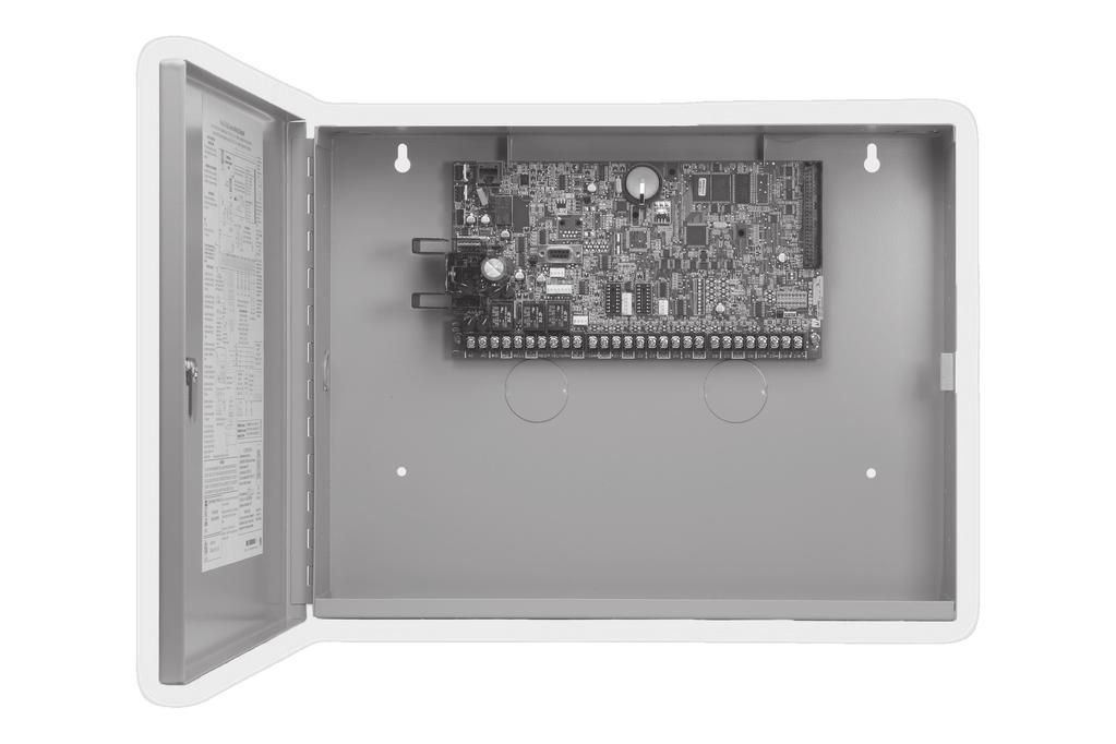
14 INTRODUCTION Installation 4.1 Mounting the Enclosure The metal enclosure for the XR500 eries must be mounted in a secure, dry place to protect the panel from damage due to tampering or the elements. It is not necessary to remove the XR500 eries PCB when installing the enclosure. Figure 2 shows the mounting hole locations for the Model 350/350A Enclosures. Figure 3 shows the Model 341 Kiosk Enclosure. Figure 4 shows the Model 352X panel cabinet and 352 shelf cabinet for multiple batteries. The 350A Attack Resistant enclosure is factory shipped with one knockout on the top left of the enclosure. As needed, additional knockouts or antenna exits may be added at the time of installation. ee Figure 2 for the positions on the enclosure that can be added. Each additional knockout must be filled with conduit. Note: When using the XR500 eries panel for listed applications, use the Model 350, 349, 341, or 352 enclosure for standby batteries. When using the 352X or 352 in listed applications, the enclosure must be surface mounted on the wall. Enclosure Mounting Holes * J3 Phone Line Power LED Link LED Activity LED R LX 3 J1 Ethernet 1 Tamper R LX-Bus XR500 eries Panel OVC Output 1 Output 2 J6 Interface Card Expansion Connector 3-Hole Pattern for Accessory Modules Battery tart J10 J8 PROG K6 Out1 Out2 J11 K Outputs 3-6 J16 Reset AC +B BELLGND MK GND GND AC B GND GND GND RED YEL GRN BLK Z1 Z2 Z3 Z4 Z5 Z6 Z7 Z8 Z9+ Z9 Z10+Z * * Dual 1 3/4" and 1 3/8" Conduit Knockouts * 350A Optional Knockout Front and Rear Tamper witches for 350A Attack Resistant Enclosure * Battery helf holds up to three 7 Ah Batteries Figure 2: XR500 eries in Model 350 or 350A Enclosure * 6
15 INTALLATION PEMs for optional battery bracket Lid Mounting Holes (4 places) Lid Mounting Holes (4 places) XR500 eries Panel J3 Phone Line Tamper Link LED Activity LED J1 Ethernet 1 Power 3 LED R L X R LX-Bus Output 1 OVC Output 2 Battery tart J10 J8 PROG K6 Out1 Out2 J11 K Outputs 3-6 J16 Reset AC +B BELLGND MK GND GND AC B GND GND GND RED YEL GRN BLK Z1 Z2 Z3 Z4 Z5 Z6 Z7 Z8 Z9+ Z9 Z10+ Z Enclosure Mounting Holes (4 places) Dual 1/2" and 3/4" Conduit Knockouts Figure 3: XR500 eries in Model 341 Enclosure 100 VA Transformer Mounting Plate J3 Phone Line 3 Power LED Tamper J1 Ethernet 1 R LX-Bus XR500 eries Command Processor Panel Output 1 Output 2 J6 Interface Card Expansion Connector Battery tart J10 J8 PROG K6 Out1 Out2 K7 J11 Outputs 3-6 J16 Reset AC AC +B B BELLGND RED YEL GRN BLK MK GND Z1 GND Z2 Z3 GND Z4 Z5 GND Z6 Z7 GND Z8 Z9+ Z9 Z10+Z Mounting for one (1) Zone Expansion Module. Battery helf Figure 4: XR500 eries in Model 352X Enclosure and eparate 352 Enclosure with helves 7
16 INTALLATION 4.2 Mounting Keypads and Zone Expansion Modules DMP LCD keypads have removable covers that allow you to easily mount the keypad to a wall or other flat surface using the screw holes on each corner of the base. Before mounting the base, connect the keypad wire harness leads to the keypad cable from the panel and to any device wiring run to that location. Then attach the harness to the pin connector on the PC board, mount the base, and install the keypad cover making sure all of the keys extend through their respective holes. For mounting keypads on solid walls, or for applications where conduit is required, use the Model /2 deep or the Model 696 1/2 deep backboxes. The DMP 711, 712-8, 714, 715, 716, and 717 modules are each contained in molded plastic housings with removable covers. The base provides you with mounting holes for installing the unit to a wall, switch plate, or other surface. 4.3 Connecting LX-Bus and Keypad Bus Devices everal factors determine the DMP LX-Bus and keypad bus performance characteristics: the wire length and gauge used, the number of devices connected, and the voltage at each device. When planning an LX-Bus and keypad bus installation, keep in mind the following information: 1. DMP recommends using 18 or 22-gauge unshielded wire for all keypad and LX-Bus circuits. Do not use twisted pair or shielded wire for LX-Bus and keypad bus data circuits. 2. On keypad bus circuits, to maintain auxiliary power integrity when using 22-gauge wire do not exceed 500 feet. When using 18-gauge wire do not exceed 1,000 feet. To increase the wire length or to add devices, install an additional power supply that is listed for Fire Protective ignaling, power limited, and regulated (12 Vdc nominal) with battery backup. Note: Each panel allows a specific number of supervised keypads. Add additional keypads in the unsupervised mode. Refer to the panel installation guide for the specific number of supervised keypads allowed. 3. Maximum distance for any one bus circuit (length of wire) is 2,500 feet regardless of the wire gauge. This distance can be in the form of one long wire run or multiple branches with all wiring totaling no more than 2,500 feet. As wire distance from the panel increases, DC voltage on the wire decreases. Maximum number of LX-Bus devices on the first 2,500 foot circuit is 40 devices. 4. Maximum voltage drop between the panel (or auxiliary power supply) and any device is 2.0 Vdc. If the voltage at any device is less than the required level, add an auxiliary power supply at the end of the circuit. When voltage is too low, the devices cannot operate properly. For additional information refer to the LX-Bus/Keypad Bus Wiring Application Note (LT-2031). Expansion Interface Cards (Models 481, 462N, 462P, 463C, C and H) The LX-Bus provided on these cards requires only a 4-wire cable between the card and any devices connected to the bus. You can connect devices (zone or output expansion modules) together on the same cable or provide separate runs back to the card. Each LX-Bus provides up to 100 zones or outputs. 4.4 Wireless Keypad Association RCV J8 Enable Wireless Keypad Association operation on both the keypad and panel. XMIT To enable association operation in the keypad, access the Installer Options Menu (3577 Programming (INT)) and select RF urvey). The keypad logo LEDs turn on Red until association is successful. To enable association operation in the XR500 panel, reset panel 3 times within 12 seconds. Allow the keypad bus Transmit/Receive LEDs to turn back on between each reset. Figure 5: Keypad Bus LEDs For 60 seconds the panel listens for wireless keypads that are in the Installer Options Menu (3577 CMD) and have not been programmed, or associated into another panel. Those keypads are assigned to the first open device position automatically based upon the order in which they are detected. The keypad logo turns Green to indicate it has been associated with the panel. 8
17 Primary Power upply INTALLATION 5.1 AC Terminals 1 and 2 Connect the transformer wires to terminals 1 and 2 on the panel. Use no more than 70 ft. of 16 gauge or 40 ft. of 18 gauge wire between the transformer and the XR500 eries. Always ground the panel before applying power to any devices: The XR500 eries must be properly grounded before connecting any devices or applying power to the panel. Proper grounding protects against Electrostatic Discharge (ED) that can damage system components. ee the Earth ground section. 5.2 Transformer Types Use Model 327 (16.5 VAC 50 VA) plug-in or Model 322/323 (16 VAC 56 VA), or 324/324P (16 VAC 100 VA) wire-in transformer. Use Model 322/323 or 324/324P wire-in transformers when required by the Authority Having Jurisdiction (AHJ). The transformer must be connected to an unswitched 120 VAC 60 Hz electrical outlet with at least.87a of available current. Never share the transformer output with any other equipment. 5.3 J12 3-Pin Header for Transformer Types Place the jumper on the left two pins labeled 50VA for a Maximum 2 Amp (Bell+Aux+moke=2 Amp) when using the Model 322/323 56VA, or VA plug-in transformer (default). Place the jumper on the right two pins labeled 75VA for a Maximum 3 Amp (Bell+Aux+moke=3 Amp) when using the Model 324/324P 100 VA wire-in transformer. Note: For UL Commercial Fire installations, refer to the Universal Fire Alarm pecifications, Transformer section, for more information. econdary Power upply 6.1 Battery Terminals 3 and 4 Connect the black battery lead to the negative battery terminal. The negative terminal connects to the enclosure ground internally through the XR500 eries circuit board. Connect the red battery lead to the battery positive terminal. Observe polarity when connecting the battery. You can add a second battery in parallel using the DMP Model 318 Dual Battery Harness. DMP requires each battery be separated by a PTC in the battery harness wiring to protect each battery from a reversal or short within the circuit. ee Figure Battery Harness For listed installations, all batteries shall be installed in a DMP Model 350 or Model 352 enclosure and all wiring shall run through conduit. The enclosure shall be installed to the left of the XR500 eries enclosure to ensure Battery and AC wire separation. Use sealed lead-acid batteries only: Use the DMP Model 364 (12 Vdc 1.3Ah), DMP Model 365 (12 Vdc 9 Ah), Model 366 (12 Vdc 18 Ah), Model 368 (12 Vdc 5.0 Ah), or Model 369 (12 Vdc 7 Ah) sealed lead acid rechargeable battery. Batteries supplied by DMP have been tested to ensure proper charging with DMP products. GEL CELL BATTERIE CANNOT BE UED WITH THE XR500 ERIE PANEL. 6.2 Earth Ground (GND) To provide proper transient suppression, XR500 eries panel terminal 4 must be connected to earth ground using 14 gauge or larger wire. DMP recommends connecting to a cold water pipe, ground rod, or building ground only. Do not connect to an electrical ground or conduit, sprinkler or gas pipes, or to a telephone company ground. 6.3 Battery Only Restart When powering up the XR500 eries panel without AC power, briefly short across the battery start pads to pull in the battery cutoff relay. The leads need a momentary short only. Once the relay has pulled in, the battery voltage holds it in that condition. If the XR500 eries panel is powered up with an AC transformer, the battery cutoff relay is pulled in automatically. For more information refer to Figure 1. Battery Battery PTC 318 Battery Harness PTC Red Black Red Black Battery To AC Battery tart AC XR550 Panel AC +B B Panel Red and Black Battery Cables 14 AWG to Earth Ground To Bell Circuit BELL GND 5 6 9
18 INTALLATION 6.4 Battery Replacement Period DMP recommends replacing the battery every 3 to 5 years under normal use. 6.5 Discharge/Recharge The XR500 eries battery charging circuit float charges at 13.9 Vdc at a maximum current of 1.0 Amps using a 50 VA or 56 VA transformer. Listed below are the various battery voltage level conditions: Battery Trouble: Below 11.9 Vdc Battery Cutoff: Below 10.2 Vdc Battery Restored: Above 12.6 Vdc 6.6 Battery upervision The XR500 eries tests the battery when AC power is present. The test is done every three minutes and lasts for five seconds. During the test, the panel places a load on the battery; if the battery voltage falls below 11.9 Vdc a low battery is detected. If AC power is not present, a low battery is detected any time the battery voltage falls below 11.9 Vdc. If a low battery is detected with AC power present, the test repeats every two minutes until the battery charges above 12.6 Vdc indicating the battery has restored voltage. If a weak battery is replaced with a fully charged battery, the restored battery will not be detected until the next two minute test is completed. 6.7 Battery Cutoff The panel disconnects the battery any time the battery voltage drops below 10.2 Vdc. This prevents battery deep discharge damage. 10
19 INTALLATION 6.8 XR500 eries Power Requirements During AC power failure, the XR500 eries panel and all connected auxiliary devices draw their power from the battery. All devices must be taken into consideration when calculating the battery standby capacity. The following table lists the XR500 eries panel power requirements. You must add the additional current draw of keypads, zone expansion modules, smoke detector output, and any other auxiliary devices used in the system for the total current required. The total is then multiplied by the number of standby hours required to calculate the total ampere-hours required. tandby Battery Power Calculations tandby Current Alarm Current XR500 eries Control Panel Relay Outputs 1-2 (ON) witch Grounds 3-6 (ON) Active Zones 1-8 Active Zones Wire moke Detectors Panel Bell Output Qty 1_ x 180mA 180 ma 30mA 5mA 1.6mA 4mA 0.1mA Qty 1_ x 180mA 180 ma 30mA 5mA 2mA* 30mA 0.1mA 1500mA ma 893A Dual Phone Line Module x 12mA x 50mA 461 Interface Adaptor Card 7mA 7mA 462N Network Interface Card x 50mA x 50mA 462P Printer Interface Card x 50mA x 50mA 463C CDMA Cellular Communicator x 22mA x 22mA C CDMA Cellular Communicator x 15mA x 48mA H HPA+ Cellular Communicator x 15mA x 48mA 481 Expansion Interface Card x 15mA x 15mA 1100X Wireless Receiver x 46mA x 46mA 1100XH Wireless High Power Receiver x 160mA x 160mA 860 Relay Output Module (one relay active) All four relays active x 34mA 138mA x 34mA 138mA 865 tyle Y or Z Notification Module x 26mA x 85mA 866 tyle W Notification Module x 45mA x 76mA 867 LX-Bus tyle W Notification Module x 30mA x 86mA 869 Dual tyle D Initiating Module x 25mA x 75mA 630F Remote Fire Command Center x 63mA x 92mA 7060/7160 Thinline/7060A Aqualite Keypad x 72mA x 80mA 7063/7163 Thinline/7063A Aqualite Keypad x 85mA x 100mA 7070/7170 Thinline/7070A Aqualite Keypad Active Zones (EOL Installed) 7073/7173 Thinline/7073A Aqualite Keypad Active Zones (EOL Installed) 7872 Graphic Touchscreen Keypad Active Zones (EOL Installed) 7873 Graphic Touchscreen Keypad Active Zones (EOL Installed) 734 Wiegand Interface Module Active Zones (EOL Installed) Annunciator (ON) 734N Wiegand Interface Module Active Zones (EOL Installed) Annunciator (ON) Wiegand Reader 734N-WiFi Wiegand Interface Module Active Zones (EOL Installed) Annunciator (ON) Wiegand Reader x 72mA 1.6mA x 85mA 1.6mA x x 145mA 1.6mA x x 143mA 1.6mA x x x x x x x x 15mA 1.6mA 146mA 1.6mA 200mA 146mA 1.6mA 200mA x x 87mA 2mA* x x 100mA 2mA* x x 215mA 2.0mA x x 243mA 2.0mA x x x x x x x x x x x 15mA 2mA* 20mA 148mA 2mA* 20mA 200mA 148mA 2mA* 20mA 200mA Copy ub-totals to next page ub-total tandby ma ub-total Alarm ma *Based on 10% of active zones in alarm. 11
20 INTALLATION tandby Battery Power Calculations tandby Current Alarm Current 736P POPIT Interface Module Radionics Popex, POPITs, OctoPOPITs Qty x x 25mA ma x x 25mA ma 738A Ademco Wireless Interface Module x 75mA x 75mA 710 Bus plitter/repeater Module x 32mA x 32mA 711 Zone Expansion Module Active Zone (EOL Installed) 714 Zone Expansion Module Active Zones (EOL Installed) Zone Expansion Module Active Zones (EOL Installed) 714-8, Zone Expansion Module Active Zones (EOL Installed) 715 Zone Expansion Module Active Zones (EOL Installed) 2-Wire mokes 715-8, Zone Expansion Modules Active Zones (EOL Installed) 2-Wire mokes 716 Output Expansion Module Active Form C Relays 717 Graphic Annunciator Module Annunciator Outputs x x x x x x x x x x x x x x 11mA 1.6mA 7mA 1.6mA 17mA 1.6mA 20mA 1.6mA 7mA 4mA.1mA 20mA 4mA.1mA x 13mA x 10mA x x x x x x x x x x x x x x x x x x 11mA 2mA* 7mA 2mA* 17mA 2mA* 20mA 2mA* 7mA 30mA*.1mA 20mA 30mA*.1mA 13mA 12mA 10mA 1mA 521LX, 521LXT moke Detectors x 8.8mA x 28mA* 2W-BLX, 2WT-BLX moke Detectors x 11mA x 31mA* COMOD2W Module COMO-2W moke and CO Detectors x x 45mA 1mA x x 174mA*# 50mA*# 572 Indicator LED x 20mA x 20mA Aux. Powered Devices on Terminals 7 and 11 Other than Keypads and LX-Bus Modules ma ma ub-totals this page only ub-total tandby ma ub-total Alarm ma ub-totals from previous page ub-total tandby ma ub-total Alarm ma *Based on 10% of active zones in alarm Total tandby ma Total Alarm ma # For systems that are not central station monitored, multiply alarm current by 12. Total tandby ma x number of tandby Hours needed = ma-hours Total Alarm ma + ma-hours Total ma-hours X.001 = Amp-hrs Required Refer to section 6.9 for standby battery selection. 12
21 INTALLATION 6.9 tandby Battery election To choose the type and number of batteries needed for 24, 60, or 72 hours of standby power based on the Amp Hours Required calculation from section 6.8 XR500 eries Power Requirements, perform the following: 1. elect the desired standby hours required from the table below: 24, 60, or 72 hours 2. elect the desired battery size: Model 368 (12 Vdc 5.0 Ah), Model 369 (12 Vdc 7 Ah), Model 365 (12 Vdc 9 Ah), Model 366 (12 Vdc 18 Ah), or Model 364 (12 Vdc 1.3 Ah) when used in the Model 341 enclosure. 3. elect a Max. Ah Available number that is just greater than the number calculated in Amp Hours Required. 4. Install the number of batteries shown in the corresponding No. of Batteries required column. Example: If the Amp Hours Required calculation equals 22 Ah for 24 hours of standby time and 4.5 Ah batteries are desired, install six (6) Model 368 (12 Vdc, 5.0 Ah) batteries. Note: You can use a Model 327 Plug-in 50 VA or Model 322/323 Wire-in 56 VA with up to 36 Ah of batteries. The Model 324/324P Wire-in 100 VA Transformer may be used with any of the battery choices listed below. For listed installations, all batteries shall be installed in a DMP Model 341, 349, 350 or 352 enclosure and all wiring shall run through conduit. The enclosure shall be installed to the left of the XR500 eries enclosure to ensure Battery and AC wire separation. 24 hours of standby power 5.0 Ah Batteries 7 Ah Batteries 7.7 Ah Batteries 9 Ah Batteries 18 Ah Batteries Max. Ah Available No. of Batteries Max. Ah Available No. of Batteries Max. Ah Available No. of Batteries Max. Ah Available No. of Batteries Max. Ah Available No. of Batteries Note: 48 hours is the typical battery recharge time for any of the Number of Batteries shown in this section. 60 hours of standby power 7 Ah Batteries 7.7 Ah Batteries 9 Ah Batteries 18 Ah Batteries Max. Ah Available No. of Batteries Max. Ah Available No. of Batteries Max. Ah Available No. of Batteries Max. Ah Available No. of Batteries Note: 48 hours is the typical battery recharge time for any of the Number of Batteries shown in this section hours of standby power 9 Ah Batteries 18 Ah Batteries Max. Ah Available No. of Batteries Max. Ah Available No. of Batteries Note: 72 hours is the typical battery recharge time required for any of the Number of 67 8 Batteries shown in this section. Note: If the Amp Hours Required calculation is greater than any Max. Ah Available number shown on a table, then add power supply(s) to power some system devices allowing the Amp Hours Required calculation to be reduced. ee the 710 Bus plitter/repeater Installation Guide (LT-0310). 13
INSTALLATION GUIDE XR100 SERIES CONTROL PANEL
 INTALLATION GUIDE XR100 ERIE CONTROL PANEL MODEL XR100 ERIE CONTROL PANEL INTALLATION GUIDE FCC NOTICE This equipment generates and uses radio frequency energy and, if not installed and used properly in
InstallatIon GuIde XR100 series canadian control Panel
 Installation Guide XR100 eries canadian Control Panel MODEL XR100 ERIE CANADIAN CONTROL PANEL INTALLATION GUIDE INDUTRY CANADA NOTICE This Class A digital apparatus complies with Canadian ICE-003. 2015,
InstallatIon GuIde XR500FC series Command PRoCessoR Panel
 Installation Guide XR500FC eries Command Processor Panel MODEL XR500FC, XR500NFC COMMAND PROCEOR INTALLATION GUIDE FCC NOTICE This equipment generates and uses radio frequency energy and, if not installed
INSTALLATION GUIDE XR100 SERIES COMMAND PROCESSOR PANEL
 INSTALLATION GUIDE XR100 SERIES COMMAND PROCESSOR PANEL MODEL XR100 SERIES ACCESS CONTROL COMMAND PROCESSOR PANEL INSTALLATION GUIDE Contains installation instructions for use with the Model XR100 and
InstallatIon GuIde XR2500F addressable FIRe alarm ContRol Panel
 Installation Guide XR2500F ADDREABLE FIRE ALARM CONTROL Panel MODEL XR2500F COMMAND PROCEOR INTALLATION GUIDE FCC NOTICE This equipment generates and uses radio frequency energy and, if not installed and
INSTALLATION GUIDE XR150/XR550 SERIES CONTROL PANEL
 GUIDE XR150/XR550 SERIES CONTROL PANEL MODEL XR150/XR550 SERIES INSTALLATION GUIDE FCC NOTICE This equipment generates and uses radio frequency energy and, if not installed and used properly in strict
InstallatIon GuIde XR500 series CanadIan ContRol Panel
 Installation Guide XR500 Series CANADIAn control Panel MODEL XR500, XR500N, XR500E CANADIAN INSTALLATION GUIDE INDUSTRY CANADA NOTICE This Class A digital apparatus complies with Canadian ICES-003. 2015,
INSTALLATION GUIDE XTLN-WIFI PANEL
 INSTALLATION GUIDE XTLN-WIFI PANEL MODEL XTLN-WiFi INSTALLATION GUIDE FCC NOTICE This equipment has been tested and found to comply with the limits for a Class B digital device, pursuant to part 15 of
Installation Guide. XR5FC and XR5SL
 Installation Guide XR5FC and XR5L Commercial Fire Panels MODEL XR5FC/XR5L COMMAND PROCEOR INTALLATION GUIDE FCC NOTICE This equipment generates and uses radio frequency energy and, if not installed and
PFC-7500/PFC-7501 Installation Manual
 PFC-7500/PFC-7501 Installation Manual Fire Alarm Communicator (All specifications subject to revision.) 5757 Phantom Dr. te 125 P.O. Box 42037 t. Louis, MO 63042 (866) 240-1870 (314) 595-6900 FAX (800)
InstallatIon GuIde XR150fc/XR550fc series Panel
 Installation Guide XR150fc/r550FC Series Panel MODEL XR150FC/XR550FC SERIES PANEL INSTALLATION GUIDE FCC NOTICE This equipment generates and uses radio frequency energy and, if not installed and used properly
INSTALLATION GUIDE XR ZONE COMMAND PROCESSOR PANEL
 INTALLATION GUIDE XR200 242-ZONE COMMAND PROCEOR PANEL MODEL XR200 COMMAND PROCEOR INTALLATION GUIDE FCC NOTICE This equipment generates and uses radio frequency energy and, if not installed and used properly
INSTALLATION GUIDE XR2400F ADDRESSABLE FIRE ALARM CONTROL PANEL
 INTALLATION GUIDE XR2400F ADDREABLE FIRE ALARM CONTROL PANEL MODEL XR2400F Addressable Fire Alarm Control Panel INTALLATION GUIDE FCC NOTICE This equipment generates and uses radio frequency energy and,
XRSuper6/XR20/XR40 Command Processor TM Panels Installation Guide
 XRuper6/XR20/XR40 Command Processor TM Panels Guide 22/26/42 Zone Burglary/Fire/Access Control Panels with Built-in Communicator 2500 N. Partnership Boulevard pringfield, MO 65803 www.dmpnet.com Digital
InstallatIon GuIde Xt series Panels
 Installation Guide XT eries Panels MODEL XT30/XT50 XT ERIE INTALLATION GUIDE FCC NOTICE This equipment has been tested and found to comply with the limits for a Class B digital device, pursuant to part
XR10/XR20 Command Processor Panels Installation Guide
 XR10/XR20 Command Processor Panels Installation Guide 10/26 Zone Burglary/Fire/Access Control Panels with Built-in Communicator LT-0229 (5/97) MODEL XR10/XR20 COMMAND PROCESSOR INSTALLATION GUIDE FCC NOTICE
INSTALLATION GUIDE XT SERIES PANELS
 INTALLATION GUIDE XT ERIE PANEL FCC NOTICE MODEL XT30/XT50 XT ERIE INTALLATION GUIDE This equipment has been tested and found to comply with the limits for a Class B digital device, pursuant to part 15
INSTALLATION GUIDE XR5FC AND XR5SL COMMERCIAL FIRE PANELS
 INSTALLATION GUIDE XR5FC AND XR5SL COMMERCIAL FIRE PANELS MODEL XR5FC/XR5SL COMMAND PROCESSOR INSTALLATION GUIDE FCC NOTICE This equipment generates and uses radio frequency energy and, if not installed
INSTALLATION GUIDE XT30INT SERIES CONTROL PANEL
 INSTALLATION GUIDE XT30INT SERIES CONTROL PANEL MODEL XT30INT CONTROL PANEL INSTALLATION GUIDE 2018, Inc. Information furnished by DMP is believed to be accurate and reliable. This information is subject
Installation Guide. XRSuper6 / XR20 / XR40
 Installation Guide XRSuper6 / XR20 / XR40 Command Processor Panels MODEL XRSuper6/XR20/XR40 COMMAND PROCESSOR INSTALLATION GUIDE FCC NOTICE This equipment generates and uses radio frequency energy and,
InstallatIon GuIde Xt series Panels
 Installation Guide XT eries Panels MODEL XT30/XT50 XT ERIE INTALLATION GUIDE FCC NOTICE This equipment has been tested and found to comply with the limits for a Class B digital device, pursuant to part
XR200 Command Processor Panel Installation Guide
 XR200 Comm Processor Panel Installation Guide 242 Zone Burglary/Fire/Access Control Panel with Built-in Communicar 2841 E. Industrial Drive pringfield, MO 65802-6310 LT-0197 (2/97) MODEL XR200 COMMAND
XTLC PANEL INSTALLATION GUIDE
 XTLC PANEL INSTALLATION GUIDE MODEL XTLC INSTALLATION GUIDE FCC NOTICE This equipment has been tested and found to comply with the limits for a Class B digital device, pursuant to part 15 of the FCC Rules.
Model 17A00 Expansion Enclosure
 HOME AUTOMATION, INC. Model 17A00 Expansion Enclosure Installation Manual Document Number 17I00-1 Rev A March, 2002 Home Automation, Inc. Model 17A00 Expansion Enclosure Installation Manual Document Number
EVO192 v3.0 Fire and Burglary What s New
 EVO192 v3.0 Fire and Burglary What s New Compatibility: EVO192 v3.0 TM50 v1.31 K641 v2.41 Overview: CP-01 Compliancy Wiring Diagram The following sections/options have been added to the EVO192 panel. They
SHORT CIRCUIT ISOLATOR TO NEXT COMPONENT REQUIRING POWER TO NEXT KEYPAD (** IF REQUIRED) STROBE RELAY MODULE KEYSWITCH ISOLATION MODULE STROBE
 STROBE RELAY MODULE KEYSWITCH ISOLATION MODULE STROBE") The Door Switch 11772 Westline Industrial Drive St. Louis, Mo 63146 (877) 998-5625 www.thedoorswitch.com Patent No. RE42,991 and RE44,039 CONTROL PANEL TRANSFORMER (SUPPLIED WITH CONTROL PANEL) NOTIFICATION
The Door Switch 11772 Westline Industrial Drive St. Louis, Mo 63146 (877) 998-5625 www.thedoorswitch.com Patent No. RE42,991 and RE44,039 CONTROL PANEL TRANSFORMER (SUPPLIED WITH CONTROL PANEL) NOTIFICATION
Addressable Fire Alarm Control Panel
 PRODUCT SPECIFICATION XR2400F Addressable FACP Addressable Fire Alarm Control Panel Description The DMP XR2400F Addressable Fire Alarm Control Panel is an expandable Fire Alarm Control with built-in DACT
D2212 Control/Communicator Installation Manual
 D2212 Control/Communicator Installation Manual 15-16 Radionics Notice The material and instructions covered in this manual have been carefully checked for accuracy and are presumed to be reliable. However,
D9412GV2/D7412GV2. Approved Applications Compliance Guide. Control Panels
 D9412GV2/D7412GV2 EN Approved Applications Compliance Guide Control Panels D9412GV2/D7412GV2 Approved Applications Compliance Guide Listings and Approvals Listings and Approvals Fire UL Underwriters Laboratories
Installation Guide. Control/Communicator
 Installation Guide Control/Communicator 33120G Page 2 Copyright 2001 Radionics Contents 1.0 Introduction... 5 1.1 Listings and Approvals... 5 1.1.1 Fire... 5 1.1.2 Burglary... 5 1.2 FCC Notice... 5 1.2.1
Independent Zone Control (I.Z.C.)
") Operation and Installation Guide Independent Zone Control (I.Z.C.) DELAYED INSTANT ARMED 1 2 3 4 7 5 6 8 9 * * fi Radionics R D279A Operation & Installation Guide 46456B Page 2 Copyright 2000 Radionics
Operation and Installation Guide Independent Zone Control (I.Z.C.) DELAYED INSTANT ARMED 1 2 3 4 7 5 6 8 9 * * fi Radionics R D279A Operation & Installation Guide 46456B Page 2 Copyright 2000 Radionics
FIRE DETECTION SYSTEM SPECIFICATION FOR MODEL XR200
 FIRE DETECTION SYSTEM SPECIFICATION FOR MODEL XR200 1.0 General 1.1 Manufacturer Manufacturer of the Fire Alarm Control Panel (FACP) equipment shall be: Digital Monitoring Products, Incorporated 2500 N.
One panel offers everything you want built-in
 XT Series Z-Wave Compatible Digital Dialer GPRS Cell Modem One panel offers everything you want built-in Two-way Wireless Receiver, along with Network, Cellular, and Dialer Communications 10/100 Network
D2412 Control / Communicator Installation Manual
 D2412 Control / Communicator Installation Manual C Notice The material and instructions covered in this manual have been carefully checked for accuracy and are presumed to be reliable. However, Radionics,
DS7400Xi Addressable Control/ Communicator
 DS7400Xi Addressable Control/ Communicator DS7400Xi DS7400Xi-EXP 110VAC operation 220VAC operation Remotely Programmable WDSRP (Windows Detection Systems Remote Programming Software), allows the systems
SPEC SHEET. Simple Expansion Solutions ZONE EXPANSION MODULES: SINGLE AND MULTIPLE POINT
 SPEC SHEET Simple Expansion Solutions Expand your DMP panel options with a wide array of expansion modules. Add supervised Class B burglary zones. Connect non-powered burglary or fire type devices for
Fire Control/Communicator
 Operation and Installation Manual Fire Control/Communicator 1 2 3 4 5 12V AC,20V A, 60Hz or +24V DC 12V AC, 20V A, 60Hz or -24V DC EARTH GND BATTERY - BATTERY + 6 INITIATING A1-7 INITIATING A2-8 INITIATING
Control Panels. Control Panels for Commercial Applications. Control panels provide the central processing
 Control Panels Control Panels for Commercial Applications Control panels provide the central processing and logic for an integrated system. In a typical system, there are four major functions: inputs,
OJD ITB No Attachment E Duress Alarm Equipment Specifications
 Duress Alarm Equipment Specifications PART 1 GENERAL 1.1 SECTION INCLUDES A. Duress devices. B. Alarm control panel. C. Signaling devices. 1.2 REFERENCE STANDARDS A. NFPA 70 - National Electrical Code;
The most affordable codeless arming and disarming available with a slim new look!
 The most affordable codeless arming and disarming available with a slim new look! 7000 Series Thinline LCD Keypads offer high- quality, cost-effective security control in a stylish, sleek new design. Visual
RANGER 8600 DOWNLOADABLE CONTROL COMMUNICATOR INSTALLATION MANUAL
 RANGER 8600 DOWNLOADABLE CONTROL COMMUNICATOR INSTALLATION MANUAL TABLE OF CONTENTS GENERAL DESCRIPTION... 2 STANDARD AND OPTIONAL PARTS LIST... 2 PARTS DIAGRAM... 3 TERMINAL DRAWING AND SPECIAL NOTES...
HEXA PROGRAMMING: STREAMLINED SECTION PROGRAMMING
 -961212-0004 SOFTWARE VERSION 3.10 CONTROL PANEL RESET: Installer lock must be unlocked. ( 058: enter any value other than 147) Power down reset (1) Remove battery and AC to power down the unit. (2) Connect
SECURITY ACCESS AND SURVEILLANCE SECTION VISTA 250BP ARCHITECT AND ENGINEER SPECIFICATION FOR SECURITY SYSTEM
 SECURITY ACCESS AND SURVEILLANCE SECTION 13850 VISTA 250BP ARCHITECT AND ENGINEER SPECIFICATION FOR SECURITY SYSTEM ADEMCO Group 165 Eileen Way Syosset, New York 11791 1-800-645-7568 SECTION 13850 DETECTION
MODEL ZAC ZONE ANNUNCIATOR/CONTROLLER DESIGNED FOR ZONE ANNUNCIATION AND MONITORING
 MODEL ZAC-32 32 ZONE ANNUNCIATOR/CONTROLLER DESIGNED FOR ZONE ANNUNCIATION AND MONITORING 32 HARD WIRED ZONES CAN BE NORMALLY-OPEN OR NORMALLY-CLOSED ZONE WIRING RUNS CAN BE AS FAR AS 10,000 FEET FROM
Operation and Installation Guide. Zone Expansion Module D8125
 Operation and Installation Guide Zone Expansion Module D8125 Page 2 2004 Bosch Security Systems, Inc. Contents 1.0 Introduction...7 1.1 Guide Organization... 7 1.2 Other Literature Referenced... 7 1.3
FIRE DEPARTMENT 9 METROTECH CENTER BROOKLYN, N.Y
 dige of FIRE DEPARTMENT 9 METROTECH CENTER BROOKLYN, N.Y. 11201-3857 wew.vdertificate OF APPROVAL # 6167A (AMENDED) THIS CERTIFICATE IS REVOCABLE, NOT TRANSFERABLE and EXPIRES on OCTOBER 15, 2018 By order
Control Panel. D9412GV4/D7412GV4 v2.00. en UL Installation Instructions
 Control Panel D9412GV4/D7412GV4 v2.00 en UL Installation Instructions Control Panel Table of Contents en 3 Table of contents 1 Introduction 4 1.1 About documentation 4 1.2 Determine Bosch Security Systems,
PS6 SERIES. Installation PS6 SERIES. Power Supplies c/w Fire Panel Interface, EOL Trigger and Standby Power Option
 Installation PS6 SERIES Power Supplies PS6 SERIES Power Supplies c/w Fire Panel Interface, EOL Trigger and Standby Power Option Installation and Specifications Manual ISDPS6_SERIES 08121590 PCN15016 R05/15GR
APS-300 SERIES DUAL VOLTAGE UL 294 LISTED ACCESS CONTROL POWER SUPPLIES
 APS-300 SERIES DUAL VOLTAGE UL 294 LISTED ACCESS CONTROL POWER SUPPLIES POWER SUPPLY AND BATTERY CHARGER AC AND DC STATUS INDICATORS ENOUGH POWER TO SUPPORT UP TO 3 MAGLOCKS OR ELECTRIC STRIKES PLUS REQUIRED
VISTA-128FBP/ V128FBP-24 Commercial Fire and Partitioned Burglary Alarm Control Panel
 VISTA-128FBP/ V128FBP-24 Commercial Fire and Partitioned Burglary Alarm Control Panel Designed to integrate seamlessly with, access control, and ADEMCO s full range of fire and burglary components, the
D7212 Control/Communicator Operation and Installation Manual
 D7212 Control/Communicator Operation and Installation Manual Notice The material and instructions covered in this manual have been carefully checked for accuracy and are presumed to be reliable. However,
Integrated Security Solutions
 Integrated Security Solutions Table of Contents Control Panels 4 Keypads 8 Communication Modules 16 I/O Expanders 20 Door Control 24 Home Automation 25 RF Receivers 26 3 Our integrated security solutions
VISTA-32FB. Commercial Fire/Burg/CCTV and Access Control Platform FEATURES: Designed to integrate seamlessly with CCTV, access
 Designed to integrate seamlessly with, access control and ADEMCO s full range of fire and burglary components, the VISTA-32FB provides the ultimate protection of life and property. The UL listed Fire and
HEXA PROGRAMMING: STREAMLINED SECTION PROGRAMMING
 48ESEP-01 SOFTWARE VERSION 3.10 CONTROL PANEL RESET: Installer lock must be unlocked. (Address 058: enter any value other than 147) Power down reset (1) Remove battery and AC to power down the unit. (2)
System Manual W A R N I N G. PC6O1O Software Version 2.1
 System Manual W A R N I N G This manual contains information on limitations regarding product use and function and information on the limitations as to liability of the manufacturer. The entire manual
SOFTWARE VERSION 2.20 CONTROL PANEL RESET: Installer lock must be unlocked. (Address 255: enter any value other than 147)
") -961112-0003 SOFTWARE VERSI 2.20 CTROL PANEL RESET: Installer lock must be unlocked. ( 255: enter any value other than 147) Power down reset (1) Remove battery and AC to power down the unit. (4) Wait 3
-961112-0003 SOFTWARE VERSI 2.20 CTROL PANEL RESET: Installer lock must be unlocked. ( 255: enter any value other than 147) Power down reset (1) Remove battery and AC to power down the unit. (4) Wait 3
Installation Guide for models:
 140 58th St. Brooklyn, NY Access Power Controllers with Power Supplies Installation Guide for models: Maximal11F - Power Supply 1: 12VDC @ 3.3 amp or 24VDC @ 3.6 amp. - Power Supply 2: 12VDC @ 3.3 amp
SECURITY ACCESS AND SURVEILLANCE SECTION VISTA-128FB ARCHITECT AND ENGINEER SPECIFICATION FOR SECURITY SYSTEM
 SECURITY ACCESS AND SURVEILLANCE SECTION 13850 VISTA-128FB ARCHITECT AND ENGINEER SPECIFICATION FOR SECURITY SYSTEM ADEMCO Group 165 Eileen Way Syosset, New York 11791 1-800-645-7568 SECTION 13850 DETECTION
734N Wiegand Interface Module
 Description The Wiegand Interface Module allows you to add IP network access control capability to XR100/XR500, XR150/ XR550, and XR150INT/XR550INT Series panels using proximity or mag-stripe card readers.
MR-2602 Two Zone Fire Alarm Control Panel
 MR-2602 Two Zone Fire Alarm Control Panel Installation Manual Secutron LT-2015 Rev.3 July 2010 Table of Contents 1 Introduction 1.1 The MR-2602 Fire Alarm Control Unit... 11 1.1.1 General features...
1126 Series Ceiling Mount PIR Motion Detector
 Installation Sheet 1126 Series Ceiling Mount PIR Motion Detector Description The 1126 Series PIR (Passive Infrared) Motion Detectors are a compact wireless PIR. The 1126 Series offer 360, Wide Angle, or
Installation Guide for models:
 140 58th St. Brooklyn, NY Access Power Controllers with Power Supplies Installation Guide for models: Maximal3FD - 12VDC @ 4.6 amp or 24VDC @ 5.2 amp. - Sixteen (16) PTC protected power-limited outputs.
Fire Burglary Instruments Inc. XL-2G Gold Control/Communicator Installation Training Seminar Rev. 5/96
 Fire Burglary Instruments Inc. XL-2G Gold Control/Communicator Installation Training Seminar Rev. 5/96 XL-2G Gold Product Overview 7 Zones (6 programmable + panic or keyswitch zone) Fast Loop Response
D2412U, D2412UE Control / Communicator Installation Manual
 D2412U, D2412UE Control / Communicator Installation Manual 10/98 /N 35115D Notice FCC Notice art 15 This equipment has been tested and found to comply with the limits for a Class B digital device, pursuant
All-In-One Wireless Security System V3.2 Programming Guide. Model # MG6130 / MG6160
 All-In-One Wireless Security System V3.2 Programming Guide Model # MG6130 / MG6160 We hope this product performs to your complete satisfaction. Should you have any questions or comments, please visit www.paradox.com
Control Panel. 1.0 GENERAL SCOPE OF WORK Introduction... 2
 Architectural & Engineering Specifications Control Panel 1.0 GENERAL... 2 1.1 SCOPE OF WORK... 2 1.1.1 Introduction... 2 1.2 GENERAL CONDITIONS... 2 1.2.1 After-Sales Support... 2 1.2.2 Quality assurance...
System Introduction. Digital Communicator Specifications: Supports all Major Formats including SIA and Contact ID Event Initiated Personal Paging
 1.1 Specifications System Introduction S E C T I O N 1 Control Panel Specifications Flexible Zone Configuration: 8 Fully Programmable Zones 38 Access Codes: 32 User, 1 System Master, 2 Partition Master,
RPSMLR2 RPSMLR2BB. Panic Device Power Controller Installation Guide LISTED. Rev
 RPSMLR2 RPSMLR2BB Panic Device Power Controller Installation Guide LISTED Rev. 102715 Overview: RPSMLR2BB, RPSMLR2 will operate up to two (2) 24VDC panic hardware devices simultaneously. It is designed
30.45 Electric Release PDRP-2001
 The PDRP-2001 Fire Alarm Control Panel (FACP) is a six-zone control panel for single and dual hazard deluge and preaction applications. The FACP is compatible with conventional input devices (2-wire or
SOFTWARE VERSION 2.20 CONTROL PANEL RESET:
 -961112-0002 SOFTWARE VERSI 2.20 CTROL PANEL RESET: Installer lock must be unlocked. ( 255: enter any value other than 147) Power down reset (1) Remove battery and AC to power down the unit. (4) Wait 3
SECURITY ACCESS AND SURVEILLANCE SECTION VISTA 250FBP ARCHITECT AND ENGINEER SPECIFICATION FOR SECURITY SYSTEM
 SECURITY ACCESS AND SURVEILLANCE SECTION 13850 VISTA 250FBP ARCHITECT AND ENGINEER SPECIFICATION FOR SECURITY SYSTEM ADEMCO Group 165 Eileen Way Syosset, New York 11791 1-800-645-7568 SECTION 13850 DETECTION
HEXA PROGRAMMING: STREAMLINED SECTION PROGRAMMING
 -961212-0004 SOFTWARE VERSI 3.10 CTROL PANEL RESET: Installer lock must be unlocked. (Address 058: enter any value other than 147) Power down reset (1) Remove battery and AC to power down the unit. (2)
Data Sheet Fire Safety & Security Products. System Overview. Initiating Circuits SXL-EX FACP 7906
 s Data Sheet Fire Safety & Security Products SXL-EX Fire Alarm Control Panel Conventional Zone Fire Alarm Control Panel ARCHITECT AND ENGINEER SPECIFICATIONS Four (4) zones expandable to eight (8) zones
FMR Installation Instructions. Addressable Fire System Controller
 FMR-7033 EN Installation Instructions Addressable Fire System Controller EN 2 FMR-7033 Installation Instructions Contents Contents Contents...2 1.0 Introduction...3 2.0 Description...3 3.0 Device Mounting...3
Integrated Security Solutions
 Integrated Security Solutions Table of Contents Control Panels 4 Keypads 8 Communication Modules 16 I/O Expanders 20 Door Control 24 Home Automation 25 RF Receivers 26 2 Our integrated security solutions
6HFXULW\6\VWHP,QVWDOODWLRQDQG6HW8S*XLGH N7227AUV2 12/99
 9,67$6(D 6HFXULW\6\VWHP,QVWDOODWLRQDQG6HW8S*XLGH * N7227AUV2 12/99 Table of Contents Section 1. GENERAL DESCRIPTION...1-1 About the VISTA-10SEa...1-1 Basic Wired Zones...1-1 Optional Expansion Zones...1-1
1100X Wireless Receivers
 00X Wireless Receivers INSTALLATION GUIDE Description The 00X Wireless Receiver is compatible with all DMP wireless devices. The receiver provides two-way, supervised communication using 900 MHz frequency
VISTA-20SE INSTALLATION INSTRUCTIONS 2-PARTITIONED SECURITY SYSTEM.
 VISTA-20SE 2-PARTITIONED SECURITY SYSTEM INSTALLATION INSTRUCTIONS Principal changes between the VISTA-20SE and the former VISTA-20 are indicated by margin lines. N7526V4 8/97 RECOMMENDATIONS FOR PROPER
9,67$&1 6HFXULW\6\VWHP ,QVWDOODWLRQDQG6HWXS*XLGH K3892V1 4/00
 9,67$ 9,67$&1 6HFXULW\6\VWHP,QVWDOODWLRQDQG6HWXS*XLGH * K3892V1 4/00 VISTA-15/VISTA-15CN Installation & Setup Guide ii RECOMMENDATIONS FOR PROPER PROTECTION The Following Recommendations for the location
FA130CP. Installation and Set-Up Guide. K0735-1V1 4/04 Rev. A OFF FA260 3 STAY 2 AWAY 1 OFF 6 9 CHIME # 5 TEST 8 CODE B C # FA560 READY R BYPASS MAX
 MAX INSTANT READY R BYPASS AWAY ARMED READY 1 OFF MAX INSTANT READY R 2 AWAY 3 STAY BYPASS FA130CP Security System Installation and Set-Up Guide ARMED READY A B C D 7 4 1 OFF FA260 2 AWAY 5 TEST 8 CODE
Control Panels D9412GV4/D7412GV4/D7212GV4. Approved Applications Compliance Guide
 Control Panels D9412GV4/D7412GV4/D7212GV4 en Approved Applications Compliance Guide GV4 Series Approved Applications Compliance Guide Listings and Approvals GV4 Listings and Approvals Fire UL The D9412GV4
INSTALLATION MANUAL PC25OO
 INSTALLATION MANUAL PC25OO NOTES ON UL INSTALLATION This equipment is UL listed in accordance with UL standard 1023 (Household Burglar Alarm System Units), UL standard 985 (Household Fire Warning Units)
For a red enclosure add an R suffix to the part # e.g. eflow4na8dr. Altronix Corp th St. Brooklyn, NY. Installing Company: Service Rep.
 Power Supply/Chargers Installation Guide Models Include: eflow4na8d - 4A @ 12VDC or 24VDC - Eight (8) PTC Outputs eflow6na8d - 4A @ 12VDC or 24VDC - Eight (8) PTC Outputs eflow102na8d - 10A @ 12VDC - Eight
TECHNICAL DATA OBSOLETE
 Deluge Devices 270a 1. PRODUCT NAME VIKING PAR-3 Available since 1991 2. MANUFACTURED FOR: THE VIKING CORPORATION 210 N. Industrial Park Road Hastings, Michigan 49058 U.S.A. Telephone: (269) 945-9501 (877)
TABLE OF CONTENTS. General Description Standard and Optional Parts List Feature Definitions Comments about the 8600E...
 5$1*(5( DOWNLOADABLE CONTROL COMMUNICATOR INSTALLATION MANUAL TABLE OF CONTENTS General Description... 2 Standard and Optional Parts List... 2 Feature Definitions... 3 Comments about the 8600E... 4 Terminal
AL802ULADA. NAC Power Extender. Installation Guide. (See Application Guide for additional information) Rev
 Rev") AL802ULADA NAC Power Extender Installation Guide (See Application Guide for additional information) Rev. 031703 Overview: The Altronix AL802ULADA is an extremely cost effective 8 amp voltage regulated
AL802ULADA NAC Power Extender Installation Guide (See Application Guide for additional information) Rev. 031703 Overview: The Altronix AL802ULADA is an extremely cost effective 8 amp voltage regulated
RANGER 7600 DOWNLOADABLE CONTROL COMMUNICATOR INSTALLATION MANUAL
 RANGER 7600 DOWNLOADABLE CONTROL COMMUNICATOR INSTALLATION MANUAL TABLE OF CONTENTS 1. TABLE OF CONTENTS... P.1 2. GENERAL DESCRIPTION... P.2... 3. STANDARD AND OPTIONAL PARTS LIST... P.2... 4. FEATURE
INTRODUCTION. The use of any power source other than a PC4204 to repower the Combus will result in a system malfunction.
 INTRODUCTION The PC4020 is a highly flexible and versatile control which will enable the installer to meet the most demanding security requirements. The heart of the system is the main control panel, designated
D2071A Fire Control/Communicator Digital Alarm Communicator Transmitter (DACT)
") D2071A Fire Control/Communicator Digital Alarm Communicator Transmitter (DACT) Installation and Programming Manual 74-06200-000-C 12/98 1998 Radionics, Inc. FCC Notice This equipment generates, uses and
D2071A Fire Control/Communicator Digital Alarm Communicator Transmitter (DACT) Installation and Programming Manual 74-06200-000-C 12/98 1998 Radionics, Inc. FCC Notice This equipment generates, uses and
734 Weigand Interface Module INSTALLATION AND PROGRAMMING GUIDE
 734 Weigand Interface Module INSTALLATI AND PROGRAMMING GUIDE TABLE OF CTENTS About the 734... 1 Power Supply... 1 Zone Terminals... 1 Annunciators... 1 Indicator LEDs... 1 Form C Relay... 2 Programming
System Introduction. 1.1 PC5015 Specifications S E C T I O N 1
 1.1 PC5015 Specifications System Introduction S E C T I O N 1 Flexible Zone Configuration: 8 Fully Programmable Zones 38 Access Codes: 32 User, 1 System Master, 2 Partition Master, 2 Duress and 1 maintenance
For a red enclosure add an R suffix to the part # e.g. eflow4na8r. Altronix Corp th St. Brooklyn, NY. Installing Company: Service Rep.
 Power Supply/Chargers Installation Guide Models Include: eflow4na8-4a @ 12VDC or 24VDC - Eight (8) Fused Outputs eflow6na8-4a @ 12VDC or 24VDC - Eight (8) Fused Outputs eflow102na8-10a @ 12VDC - Eight
P Zone Expandable Hybrid Security System
 Page 1 of 11 up to 8 hardwired keypads and 4 wireless keypads 4 hardwired keypads available with zone input PWLS910 wireless handheld keypad added wireless control is provided by - PWLS908 wireless panic
D2071A. Operation & Installation Guide Fire Alarm Control Panel
 D2071A EN Operation & Installation Guide Fire Alarm Control Panel D2071A Operations & Installation Guide Contents Contents 1.0 Overview... 4 1.1 Communicator... 4 1.2 RFI and Lightning Protection... 4
Remote NAC Power Supply D7038
 Operation and Installation Guide Remote NAC Power Supply D7038 D7038 REMOTE NAC POWER SUPPLY Page 2 2005 Bosch Security Systems Contents Contents 1.0 Overview...5 1.1 Module Control...5 1.1.1 Option Bus
RANGER 8980E DOWNLOADABLE CONTROL COMMUNICATOR INSTALLATION MANUAL
 RANGER 8980E DOWNLOADABLE CONTROL COMMUNICATOR INSTALLATION MANUAL TABLE OF CONTENTS GENERAL DESCRIPTION...2 STANDARD AND OPTIONAL PARTS LIST...2 FEATURE DEFINITIONS...3 TERMINAL DRAWING AND SPECIAL NOTES...4
Long Range Radio Alarm Transmitter
 W A R N I N G Please refer to the System Installation Manual for information on limitations regarding product use and function and information on the limitations as to liability of the manufacturer. TM
System Introduction. 1.1 Specifications S E C T I O N 1
 System Introduction S E C T I O N 1 1.1 Specifications Control Panel Specifications Flexible Zone Configuration: 8 Fully Programmable Zones 37 Access Codes: 32 User, 1 System Master, 2 Partition Master
INSTALLATION AND PROGRAMMING GUIDE. XTLplus SERIES PANELS
 ITALLATIO AD PROGRAMMIG GUIDE XTLplus ERIE PAEL MODEL XTLplus ERIE ITALLATIO AD PROGRAMMIG GUIDE FCC OTICE This equipment has been tested and found to comply with the limits for a Class B digital device,
FireNET Plus Wiring Instructions
 FireNET Plus Wiring Instructions This manual provides wiring instructions for the 1 loop and 2 loop version of the FireNET Plus panels, which supports our finest Hochiki s DCP protocol. Note: Refer to