BENTEL SECURITY srl reserves the right to modify the technical specifications of this product without prior notice.
|
|
|
- Earl Doyle
- 6 years ago
- Views:
Transcription


1
2 BENTEL SECURITY srl reserves the right to modify the technical specifications of this product without prior notice. via Florida - Z.I. Valtesino GROTTAMMARE (AP) - ITALY USER MANUAL: Digital communicator control panels Omnia8/Omnia4 ISTRUZIONI INGLESE USO CEN. OMNIA4/8-UK ISTOMNIA4/8USO-UK
3 CONTENTS OVERVIEW 5 The Omnia8 and Omnia4 control panels Glossary GENERAL FEATURES 7 The Main Unit The keypad Digital key Arming Mode Options DIGITAL KEY CONTROL 13 Global arming Global disarming Type A arming (Amber) Type B arming (green) Stop alarm CONTROL FROM KEYPAD 15 Basic options Global arming Global disarming Type A or Type B arming Zone bypass View armed partitions View bypassed zones User Menu Options from keypad Reset Alarm Memory Enable / Disable auto arming Enable / Disable Teleservice Overtime Request Teleservice Request Enable / Disable Silent keypad Enable / Disable Hidden zone status on keypad
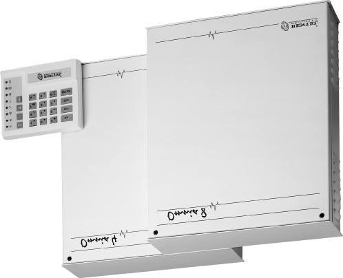
4 Alarm Device Test User Code PIN Programming Stop alarm Stop all Calls Superkeys Instant alarm call View Alarm Memory Trouble Viewing mode APPENDIX 25 Zones insert Programming sheets Figure 1 Omnia8 system components 4 Security System Control Panels Omnia8/Omnia4
5 OVERVIEW The Omnia8 and Omnia4 control panels Omnia8 is a security system with 8 zones and 4 partitions. Omnia4 is a security system with 4 zones and 4 partitions. The basic systems comprises a Main Unit, a built-in communicator and 1 keypad. The Control panels can control up 16 remote devices (key readers / keypads), with a maximum of 8 keypads including the one supplied, and 128 different digital keys. Communicator Voice messages The built-in Digital Communicator can manage 8 telephone numbers for communication with central stations and teleservice. The optional NormaVOX2 voice board can record and send up to 8 voice messages to 1 or more of the 8 programmed telephone numbers. All the Control panel features are described in this manual. Your Installer will provide further details for proper use of the system. Figure 1 shows a Omnia8 system with a Main Unit, keypad, key reader and digital key. Digital keys, although not indispensable, greatly simplify system control. Glossary Arming Disarming Alarm Keypad Digital Key Key Reader Alarm Zone Partition An option which puts the system IN SERVICE. Violation of the armed partitions will generate an alarm. An option which puts the system OUT-OF-SERVICE. Violation of the disarmed partitions will not generate an alarm. A status which signals violation. Immediate intervention of authorized persons will be required. Set of keys (on keypad) used for manual control of the Omnia8 and Omnia4 systems. An electronic control key with a random code (selected from over 4 billion combinations). A device which reads the digital key. A zone where one or more sensors can be connected. A group of zones that allow system partitioning, each partition can have its own specific Times, Code PINs and digital keys. OVERVIEW 5
6 Exit Time A programmed delay which starts after the system arming. ATTENTION! All persons must leave the protected zone before the delay ends, otherwise the control panel will generate an alarm. Entry Time A programmed delay which starts after violation of a delayed zone. ATTENTION! The system must be disarmed before the delay ends. Delayed Zone A zone which allows transit. ATTENTION! An alarm will be generated if the programmed Exit / Entry time is not respected. Zone Bypass An option which excludes a zone. ATTENTION! Violation of a bypassed zone will not generate an alarm. Tamper Zone Alarm Memory A zone which is active 24 hours per day (24h zone), regardless of the armed / disarmed status of the system. An alarm will be generated in the event of tamper on any of the system components. A feature which records alarm events. The Alarm Memory can be cleared by means of Automatic or Manual RESET. Codes 23 Codes are available for the user. The Installer can assign one of the 5 Code Types: - DISABLED - MAIN USER - USER - DURESS - PATROL to each of the 23 codes. Each code can control specific options and partitions according to programming. Main User Type codes can assign a 4 to 6 digit PIN to the other Code Types. When a Code PIN is entered on a keypad it can enable / disable the options on the partitions it can control, and on the partitions of the keypad in use. User Pin Installer Pin Teleservice Central Station Telemonitoring A modifiable 4 to 6 digit number, programmed by the Main User, which can access the system. A modifiable 4 to 6 digit number which allows the Installer to access and program the control panel parameters. A service provided by the Installer. The Teleservice feature allows the Installer to service the control pane via telephone. A specialized operations centre that receives and responds to alarm signalling. A service provided by the Central Station. The Telemonitoring function is for remote control of the system, and communicates coded events to the Central Station. 6 Security System Control Panels Omnia8/Omnia4
7 GENERAL FEATURES The Main Unit The Main Unit houses the main board, power supply unit, battery, and the terminals for the connections of the Sensors, Sirens and auxiliary devices. The keypad The Control panel can be programmed and controlled from the keypads. INDICATOR Arm Alarm Trouble Ready 24h Open Bypass Program. OFF: OFF: slow flashing: fast flashing: OFF: slow flashing: OFF: OFF: slow flashing: fast flashing: OFF: slow flashing: OFF: slow flashing: fast flashing: STATUS All partitions (enabled on the keypad) are disarmed At least one Partition (enabled on the keypad) is armed Standby status (no alarm) Alarm memory Alarm status No trouble Trouble: use the Trouble Viewing Mode to identify the trouble type Trouble Viewing Mode running Ready to arm: ----arming will not generate an alarm At least one unbypassed zone is in alarm status: ---- arming will generate an alarm Tamper line balanced Alarm memorized on the tamper line Alarm memorized and tamper line open NOT IN USE No bypassed zones At least one of the keypad zones is bypassed Control panel is ready for zone bypass Control panel in standby status Control panel enabled for Teleservice calls Control panel in programming status Control panel in service status (maintenance) GENERAL FEATURES 7
8 INDICATOR Key 1 OFF: Key 4 OFF: Key 7 OFF: Key A OFF: Key 0 OFF: TROUBLE VIEWING MODE Sensor power protection fuse intact Sensor power protection fuse blown Main Unit powered by mains Mains failure: Main Unit powered by battery Battery charged Low battery or battery trouble Communication bus normal Communication bus trouble Telephone line OK Telephone line trouble Number Keys In standby status ----the LEDs behind number keys through (corresponding respectively to the zones) will show the zone status: ----OFF indicates zone in standby status ----Slow flashing indicates alarm or tamper memorized on the zone ----Fast flashing indicates zone violation (alarm or tamper) Buzzer The audible signals emitted by the Keypad buzzer are as follows: ----Key pressed = Short beep ----Command accepted = Long high-tone beep ----Error signal = Long low-tone beep The buzzer can also signal the elapsing Entry / Exit delay. Codes 23 Codes are available for the user. The Installer can assign one of the 5 Code Types: - DISABLED - MAIN USER - USER - DURESS - PATROL to each of the 23 codes. Each code can control specific options and partitions according to programming. Main User Type codes can assign a 4 to 6 digit PIN to the other Code Types. When a Code PIN is entered on a keypad it can enable / disable the options on the partitions it can control, and on the partitions of the keypad in use. Code errors will be signalled by a Long lowtone beep, after which it will be possible to retry. MAIN USER Codes provide full control of the system options, and can access the programming phase and change the User Code PINs, therefore, should be given to persons that require full control of the system. USER Codes are enabled for Global arming / disarming, Reset Alarm Memory and Overtime requests. These Codes allow restricted control of the system, therefore, should be given to persons that do not require full control of the system. DURESS Codes are for forced disarming (disarming under threat). Entry of a Duress Code PIN will disarm the system and activate the Digital Communicator (which will send an alarm call to the Central Station), and dialler (which will send the recorded voice messages to the programmed telephone numbers). 8 Security System Control Panels Omnia8/Omnia4
9 PATROL Codes are enabled for Global arming / disarming. PATROL Code PINs can disarm partitions temporarily. Partitions disarmed by a PA- TROL Code PIN will be rearmed automatically when the programmed Patrol time elapses. The factory default programming for the User Codes can be found on page 26. Superkeys Each Superkey controls a specific option (without requiring Code PIN entry): Number keys,,, and will take on Superkey status when pressed for approximately 4 seconds (refer to "Superkeys" paragraph). GENERAL FEATURES 9
10 Digital key Key reader Digital Key Multiple Systems Key readers have 3 LEDs (Red, Green and Amber), and a digital key slot. Each key reader will be programmed with the following: -the partitions it can control -the type of arming assigned to the Amber LED -the type of arming assigned to the Green LED The digital keys control the arming mode of the partitions. The digital key must be inserted into the key reader slot. It is possible to scan the 4 configurations of the LEDs (each configuration is assigned to a specific arming mode) by simply pressing the digital key button. On the Eclipse/Sat model the button is inside the key reader, therefore, the Sat digital key must be inserted into the Eclipse key reader slot, and pushed lightly to scan the 4 configurations of the LEDs, and select the arming mode. Digital keys have a non-volatile memory with a random code selected from 4 billion code combinations. The Installer can assign a progressive number (1 through 128), and a 16 character Label to each of the 128 digital keys. Each digital key can be programmed to control specific partitions only. There are two digital key levels: Service ---- can stop all alarm types; and Non-service ----can stop alarms on the partitions of the digital key and key reader in use. Digital keys can valid on more than one system, and can be programmed to manage different groups of partitions on the different systems. Digital key in key reader Arming Mode Options When a valid digital key is inserted into a key reader, all the signalling devices of the partitions controlled by the digital key and key reader in use will be stopped. At this point, by pressing the digital key button it will be possible to scan the 4 configurations of the LEDs. Each configuration is assigned to a specific arming mode. Global arming: (Red LED ON) all the partitions controlled by the digital key and key reader in use will be armed. Global disarming: (all LEDs OFF) all the partitions controlled by the digital key and key reader in use will be disarmed. A and B type arming: (Amber or Green ON) all the partitions controlled by the digital key and key reader in use will be armed or disarmed as configured during programming. Stop alarm: all signalling devices, connected to the alarm outputs of the partitions controlled by the digital key and key reader in use will be forced into standby status. The selected arming mode (indicated by the configuration on the key reader) will be activated when the digital key is extracted. 10 Security System Control Panels Omnia8/Omnia4
11 The Control panel reads the status of the unbypassed and Instant zones assigned to the partitions to be armed. If the zones are violated (door or window open), the LED will start flashing to signal that arming the partitions will generate an alarm. To quit without changing: 1. Leave the key in the key reader. 2. Press the digital key button for about 4 seconds. 3. Extract the key when the 3 LEDs start flashing. Invalid digital keys will generate the False Key Event on the key reader, and will activate the programmed procedure. The False Key Event will be signalled by fast flashing on the 3 LEDs. No digital key in key reader When the key reader is empty (no digital key) the LEDs indicate the following: ----Red LED ON indicates that at least one of the partitions controlled by the key reader is armed. ----Red LED OFF indicates that all the partitions controlled by the key reader are disarmed. ----Amber LED ON indicates that the configuration of the armed or disarmed partitions matches the Type A arming mode of the key reader. ----Green LED ON indicates that the configuration of the armed or disarmed partitions matches the Type B arming mode of the key reader. Only the partitions controlled by the key reader affect its LEDs. The LEDs can be disabled by the Installer. Figure 2 Key reader and digital key for control of the Control panel Figure 3 Key reader and digital key for control of the Control panel - Eclipse/Sat model GENERAL FEATURES 11
12 If the configuration of the armed partitions does not match Type A or B arming (for example a key reader partition has been armed from the keypad) the Amber and Green LED will be OFF. 12 Security System Control Panels Omnia8/Omnia4
13 DIGITAL KEY CONTROL Global arming This option arms all the partitions that the digital key and key reader in use can control. 1. Insert a valid digital key into any key reader ----all 3 LEDs on the key reader will go OFF. 2. Press the digital key button once ----the Red LED will go ON to indicate a Global arming request. 3. Extract the digital key ----the controlled partitions will arm. Flashing on the Red LED signals that at least one zone is violated (door or window open), and therefore, arming will generate an alarm. Global disarming This option disarms all the partitions that the digital key and key reader in use can control. 1. Insert a valid digital key into any key reader ----all 3 LEDs will go OFF. 2. Extract the digital key ----the controlled partitions will disarm. Type A arming (Amber) This option arms specific partitions and disarms others according to the programmed configuration. 1. Insert a valid digital key into any key reader -----all 3 LEDs will go OFF. 2. Press the digital key button twice ----the Amber LED will go ON to indicate a Type A arming request. 3. Extract the digital key ----the system will arm with Type A arming configuration. Flashing on the Amber LED signals that at least one zone is violated (door or window open), and arming will generate an alarm. DIGITAL KEY CONTROL 13
14 Type B arming (green) This option will arm specific partitions and disarm others according to the programmed configuration. 1. Insert a valid digital key into any key reader ----all 3 LEDs will go OFF. 2. Press the digital key button three times ----the Green LED will go ON to indicate a Type B arming request. 3. Extract the digital key ----the system will arm with Type B arming configuration. Flashing on the Green LED indicates that at least one zone is violated (door or window open), and therefore, arming will generate an alarm. Stop alarm To stop an alarm: Insert a valid digital key into any key reader. Service digital keys can stop all alarm types (partition and system). Nonservice digital keys can only stop alarms on the partitions controlled by the digital key and key reader in use. This operation will affect the alarm memory. 14 Security System Control Panels Omnia8/Omnia4
15 CONTROL FROM KEYPAD The Omnia8 and Omnia4 systems can be controlled completely from the keypad. The Control panels offer basic options, such as: arm / disarm etc., and also a set of options for advanced control of the system. Basic options To access basic options from standby status: 1. Enter User Code PIN (4 to 6 digits). 2. Select the option Key. The keypad will lock for 3 minutes after 10 invalid code entries. User Code PINs can control the 6 basic options. The and keys can control 2 options, as per the table below. Options that require a Code PIN will only affect the partitions controlled by the Code PIN and the keypad in use. OPTION Global arming Global disarming Type A arming Type B arming Access bypass zone menu Access User menu View armed Partitions PROCEDURE Enter Code PIN then press Enter Code PIN then press Enter Code PIN then press Enter Code PIN then press Enter Code PIN then press Enter Code PIN then press Press View bypassed zones Press All Default PINs must be changed (refer to "User Code PIN Programming"). CONTROL FROM KEYPAD 15
16 Global arming <Code PIN> This option arms all the partitions controlled by the Code PIN and the keypad in use. Before starting the procedure make sure that the Green READY LED is ON (no zones violated). 1. Enter a Main User or User Code PIN. 2. Press. All the partitions controlled by the Code PIN and keypad in use will arm. The keypad buzzer will signal the elapsing delay (EXIT TIME). Global disarming <Code PIN> This option disarms all the partitions controlled by the Code PIN and the keypad in use. 1. Enter a Main User, User, Duress or Patrol Code PIN. 2. Press. All the partitions controlled by the Code PIN will disarm. All Signalling Devices, activated by a partition alarm, will be forced into standby status when the partition in question is disarmed. If a Patrol Code PIN is used, the disarmed partitions will rearm automatically when the Patrol time ends. Duress Code PINs should only be used when the User s personal safety is at risk. Duress Code PINs will disarm the system, and at the same time activate the Digital Communicator and Voice Dialler. Type A or Type B arming <Code PIN> or During the programming phase each Code will be configured for Type A arming and Type B arming. The configuration determines the partitions that will arm and disarm when a Type A or Type B arming request is made. Example: Type A arming configuration = arm partitions 1 and 4; disarm partitions 2 and Enter a Main User, User or Duress Code PIN. 2. Press or. The Control panel will arm with Type A or B arming configuration. Zone bypass <Code PIN> zone no. The zone bypass option allows the User to bypass specific zones. Only zones assigned to the partitions, and controlled by the Code PIN and keypad in use can be bypassed / unbypassed. 16 Security System Control Panels Omnia8/Omnia4
17 Before accessing the zone bypass menu disarm the partition that the zone is assigned to, otherwise, the zone bypass request will be revoked. 1. Enter a Main User Code PIN. 2. Press to access the Bypass menu. The Amber LED ESC will flash slowly. The current zone status (bypassed / unbypassed) will be shown on number keys through (assigned respectively to zones 1 through 8): ----ON indicates zone bypassed ----OFF indicates zone unbypassed 3. Bypass / unbypass the zones as required ----use the number Key to toggle the status of its assigned zone. 4. Press to quit and step back to standby status. The control panel will step back automatically if no key is pressed within 20 seconds of access. View armed partitions To view partition status (armed / disarmed): 1. Press to view the armed partitions. The key will flash. The current partition status (armed / disarmed) will be shown on keys through (assigned respectively to partitions 1 through 4): ----ON indicates partition armed ----OFF indicates partition disarmed 2. Press the key to step back to standby status. The control panel will step back automatically if no key is pressed within 20 seconds of access. View bypassed zones To view zone status (bypassed / unbypassed): 1. Press the key to view zone status. The key will flash slowly. The current zone status will be shown on keys through (assigned respectively to zones1 through 8): ----ON indicates zone bypassed ----OFF indicates zone unbypassed 2. Press the key to step back to standby status. The control panel will step back automatically if no key is pressed within 20 seconds of access. CONTROL FROM KEYPAD 17
18 User Menu Options from keypad <Code PIN> Only Main User Code PINs have full access to all the options. User Code PINs can access two options only: Reset Alarm Memory and Overtime Request. To access options: 1. Enter a Main User or User Code PIN. 2. Press. 3. Select the required option. Options from Reset Alarm Memory keypad Enable / Disable auto arming Enable / Disable Teleservice Overtime Request Teleservice Request Enable / Disable Silent option Enable / Disable hidden zone status on keypad Alarm Device Test Code PIN Programming Stop Alarms Stop Calls The Options will affect the partitions controlled by the Code PIN and keypad in use. Reset Alarm Memory <Code PIN> All zone alarms are recorded in the alarm memory. The Reset Alarm Memory option erases the alarm memory, and forces the Alarm Signalling Devices (connected to the alarm outputs) of the partitions controlled by the Code PIN into standby status. To Reset Alarm Memory: 1. Enter a Main User or User Code PIN. 2. Press. 3. Press. Only Main User Code PINs can Reset the System Tamper Alarm Memory. ATTENTION The Control panel will effect Reset Alarm Memory each time the control panel is armed, that is, if so programmed by the Installer. 18 Security System Control Panels Omnia8/Omnia4
19 Enable / Disable auto arming <Code PIN> Key toggles auto arming 1. Press when key is ON to enable auto arming. 2. Press when key is OFF to disable auto arming. 3. Press to quit without changing the current status. Enable / Disable Teleservice <Code PIN> The Installer can call the Control panel to activate Teleservice, only after the User has enabled the Teleservice option (the control panel will be able to receive incoming Teleservice calls). Key toggles Teleservice. 1. Press when key is ON to enable Teleservice. 2. Press when key is OFF to disable Teleservice. 3. Press to quit without changing. The Teleservice enabled / disabled status is also shown on the PRG LED on the keypad. Figure 4 User Options via keypad Overtime requests are possible only when auto arming is enabled CONTROL FROM KEYPAD 19
20 Overtime Request <Code PIN> If auto arming is disabled key will have no effect. If auto arming is enabled key will be OFF, and therefore, if pressed will flash slowly. Press key to activate the Overtime request, and delay the programmed auto arming time by 30 minutes The Overtime Requests will affect the partitions (established during programming) controlled by the Code PIN. When the Overtime Request on any partition goes beyond midnight (00.00 on the Timer), auto arming (if enabled) will occur at midnight. Teleservice Request <Code PIN> The User can make a Teleservice Request call (remote intervention via telephone) to the programmed Installer telephone number, only when the Installer is equipped and ready for Teleservice. The Installer Telephone number will be dialled shortly after the long-high tone beep which confirms acceptance of the Teleservice Request. Enable / Disable Silent keypad <Code PIN> The Silent option can be enabled / disabled on each keypad. When this option is enabled the keypad will not emit any sound during the elapsing Entry / Exit delay. Key toggles the Silent option 1. Press when key is ON to enable the Silent option on the keypad. 2. Press when key is OFF to disable the Silent option on the keypad. 3. Press to quit without changing the current status. Each keypad must be programmed separately. Enable / Disable Hidden zone status on keypad <Code PIN> The "Hidden" option can be enabled / disabled on each keypad. When this option is enabled the current status of the zones will not be shown on number keys through Key toggles the Hidden option 1. Press when key is ON to enable the "Hidden" option. 2. Press when key is OFF to disable the "Hidden" option. 3. Press to quit without changing the current status. Each keypad should be programmed separately. 20 Security System Control Panels Omnia8/Omnia4
21 Alarm Device Test <Code PIN> Use this option to test the alarm devices connected to the Alarm Output (e.g. Outdoor and Indoor Sirens). To test Alarm Devices: 1. Enter a Main User Code Code PIN on any keypad. 2. Press. 3. Press. The Alarm Output will be activated for approximately 2 seconds the User menu will be quitted. Not all the Alarm Devices will stop when the Alarm Output returns to standby status (e.g. telephone dialler), and therefore, must be stopped by other means (ask the Installer for details). User Code PIN Programming <Code PIN> Change User PIN Main User Code PINs can access the User Code PIN Programming phase. The Installer cannot access this phase. Access to the User Code PIN programming phase will generate the Stop alarm event, and the Stop all Calls procedures (refer to the following paragraphs). A Main User can change the assigned PIN, however, a Main User cannot change the PIN of another Main User and cannot program User Code PINs which are enabled on partitions that the Main User in question cannot control. To access the User Code PIN Programming phase in order to change the default User Code PINs (1 through 23), or to change a programmed Code PIN: 1. Enter Main User Code PIN. 2. Press. 3. Press. 4. Enter the Identifier number of the Code PIN to be changed (refer to the No. Column of the table on page 27). 5. Press. 6. Enter the new PIN (4 through 6 digits). 7. Press to confirm and step to step Press to quit programming phase. The PRG LED will stop flashing. The Installer can program the Code Type as follows: 1= DISABLED, 2=MAIN USER, 3=USER, 4=DURESS, or 5=PATROL. CONTROL FROM KEYPAD 21
22 ATTENTION Please remember that Code PINs cannot be traced, therefore, it is advisable to have a written record. The table on page 27 should be used for this purpose (the Code PIN table must be kept in a safe place). Factory default can be restored by the Installer if required. Stop alarm <Code PIN> Refer to the note in the User Code PIN Programming paragraph. Alarm status will activate the alarm signalling devices, and the Digital Communicator and Dialler. To stop an alarm procedure: Disarm the partition in alarm status To stop a tamper alarm: 1. Disarm the partition in alarm status. 2. Reset Alarm Memory (refer to "Reset Alarm Memory" paragraph). To stop a persistent alarm (e.g. generated by a sensor): 1. Enter Code PIN. 2. Press. 3. Press. All the alarm signalling devices on the partition in question will be forced into standby status. New alarms on the partition in question will be ignored. This status will be signalled by slow flashing on the PRG LED. This status will be held until is pressed. Only Main User Code PINs can stop alarms generated by system tamper. Stop all Calls <Code PIN> Refer to the note in the User Code PIN Programming paragraph. The programmed alarm calls (Event messages) will be sent to the Central Station when the assigned Event occurs. To Stop an outgoing alarm call, and clear the call queue: 1. Enter a Main User Code PIN. 2. Press. 3. Press. The PRG LED will start flashing slowly to signal access. This status will be held until is pressed. No calls will be sent while the control panel is in this status, even if other call generating events occur. 22 Security System Control Panels Omnia8/Omnia4
23 Superkeys Each Superkey controls a specific command. Superkeys commands do not require Code PINs. Press key,,, or for approximately 4 seconds. The selected key will take on Superkey status, and the assigned command will be activated. COMMAND SUPERKEY Activate Instant alarm call on the Digital Communicator and Dialler, View alarm memory, Trouble Viewing mode Instant alarm call Superkeys,, Events corresponding to superkeys, and must be programmed by the installer. The 3 alarm types (Fire, Danger and Police Request) can each be assigned to a specific Event Call. The required Event call can be activated from the keypad by pressing the corresponding key for approximately 4 seconds. The icon on the key identifies the alarm type. Fire alarm Danger alarm Police A long high-tone beep will confirm command acceptance. The Digital Communicator and Dialler will be activated shortly after. View Alarm Memory Superkey To view the alarm memory: Press key for approximately 4 seconds. A long high-tone beep will confirm command acceptance. Any alarm and / or tamper events which may occur after Reset Alarm Memory will be shown on keys through (corresponding to the zones), as follows: ----ON indicates alarm memory on the corresponding zone ----Slow flashing indicates tamper memory on the corresponding zone ----Fast flashing indicates alarm and tamper memory on the corresponding zone CONTROL FROM KEYPAD 23
24 Trouble Viewing mode Superkey To view: Press key for approximately 4 seconds A long high-tone beep will acknowledge acceptance of the command. This status will be signalled by slow flashing on the Trouble LED. Keys A (on the left side of the keypad) will indicate trouble status, as per the following table: KEYS Key 1 off: Key 4 off: Key 7 off: Key A off: Key 0 off: STATUS Sensor power protection fuse intact sensor power protection fuse blown Main Unit powered by mains Mains failure: Main Unit powered by battery Battery charged Low battery or battery trouble Communication bus OK Communication bus trouble Telephone line OK Telephone line trouble Press any key to quit the Trouble Viewing Mode. The control panel will quit this phase automatically ----if no key is pressed within 20 seconds of access. Check the trouble status each time the Trouble LED goes ON, and if necessary call your service dealer. 24 Security System Control Panels Omnia8/Omnia4
25 APPENDIX Zones insert The Zones insert, inside the package, should be filled in and kept in the holder on the keypad backplate (see figure 5). In this way, the zones insert will always be on hand when identification of a zone is necessary i.e. when a key on the keypad goes ON or starts flashing. Programming sheets The Installer should fill in the programming sheets in the following pages. The User should refer to the sheets when information regarding the security system is required. Figure 5 Zones insert and holder on keypad backplate APPENDIX 25
26 Partitions Type A Arming Type B Arming Use this row for the Partition Descriptions No. Description Type PIN User Code Factory Default Programming 1 Code 001 Main User 0001 Yes Yes Yes Yes A A A A A A A A 2 Code 002 User 0002 Yes Yes Yes Yes A A A A A A A A 3 Code 003 Duress 0003 Yes Yes Yes Yes A A A A A A A A 4 Code 004 Patrol 0004 Yes Yes Yes Yes A A A A A A A A No. Description Type PIN Partitions Type A Arming Type B Arming This is the Code identifier Number. This is the Code description. This is the Code Type. This is the Code PIN Number. The PIN allows access to the enabled options of the Code in question. This is the enabled partitions of the Code in question. These are the partitions that will be armed (A), and those that will be disarmed (D) when the Code is used for Type A Arming. These are the partitions that will be armed (A), and those that will be disarmed (D) when the Code is used for Type B Arming. 26 Security System Control Panels Omnia8/Omnia4
27 Partitions Use this row for the Partition Descriptions Add. Keypads in No. configuration Description Use this row for the Partition Descriptions Red Amber Green Add. Key readers in No. configuration Description Add. No. Partitions Red Amber This is the Device Address (Keypad or Key reader). This is the identifier number (Keypad or Key reader). These are the partitions the keypad can control. These are the partitions that will be armed when the Red LED is ON and the digital key is extracted. These are the partitions that will be Armed (A) and Disarmed (D) when the Amber LED on the key reader is ON, and the digital key is extracted. Green These are the partitions that will be Armed (A) and Disarmed (D) when the Green LED on the key reader is ON, and the digital key is extracted. APPENDIX 27
28 OPTION KEYPAD Global arming Main User or User code Type A arming Main User code or User code Type B arming Main User code or User code Disarm Main User code or User code Temporary Disarm (Patrol) Patrol code Disarm under Duress Duress code Reset Alarm Memory Main User or User code Stop alarm Main User code Stop Calls Main User code Bypass zones Main User code Enable / Disable auto arming Main User code Enable / Disable Teleservice Answer Main User code Overtime request Main User or User code Send Teleservice Call Main User code Enable / Disable Silent keypad Main User code Enable / Disable Hidden zone status on keypad Main User code Alarm Device Test Main User code User Code PINs Programming Main User code Activate Instant Alarm on communicator View alarm memory Trouble Viewing mode Superkey Superkey Superkey Superkey Superkey FOR YOUR SERVICE DEALER PLEASE CONTACT: Installer Company: Telephone: Address: Contact Person:
BENTEL SECURITY reserves the right to modify the technical features of this product without prior notice.
 BENTEL SECURITY reserves the right to modify the technical features of this product without prior notice. via Florida Z.I. Valtesino - 63013 GROTTAMMARE (AP) - ITALY Installation and Quick guide: DUAL
Contents. Glossary
 Contents Glossary ------------------------------------------------------------------------------------------------------ 6 1. Introduction to the IDS 1632 -------------------------------------------------------------
AXI LED USER MANUAL (REV. 1.0)
") Security & Home Automation System AXI LED USER MANUAL (REV. 1.0) CONTENTS PREFACE FEATURES LED KEYPAD OUTLOOK 1.0 LIGHT INDICATION 1 2 4 6 CHAPTER 1: ALARM SYSTEM CONTROL 1.0 USING LED KEYPAD 1.0.1 ARMING
Security & Home Automation System AXI LED USER MANUAL (REV. 1.0) CONTENTS PREFACE FEATURES LED KEYPAD OUTLOOK 1.0 LIGHT INDICATION 1 2 4 6 CHAPTER 1: ALARM SYSTEM CONTROL 1.0 USING LED KEYPAD 1.0.1 ARMING
Watchguard WGAP864 User Manual
 Watchguard WGAP864 User Manual v1.0 Issued September 2016 1 2 Table of Contents Glossary... 5 1. Introduction to your Watchguard WGAP864... 6 2. Before Operating your Alarm System... 6 3. Understanding
Using Your. Security System With LED Keypad S5030, S5031, S5032
 Using Your Security System With LED Keypad S5030, S5031, S5032 Contents 1 Overview Your Security System... 1 How Your Security System Works... 2 Your System's Programming... 3 Getting Used to Your System...
Alarm Control Panel WIC-16Z4P WIC-5Z2P. User Instructions
 WIC-16Z4P WIC-5Z2P User Instructions Page : 2/14 INDEX # Function Page 1 Add a New User Code 11 2 Arm or Disarm All Areas or Disarm Selected Areas (Partitioned System) 8 3 Arming the System (Away Mode)
Version 1.03 January-2002 USER S MANUAL
 Version 1.03 January-2002 1 USER S MANUAL 2 Version 1.03 January-2002 System Details CUSTOMER:...... PHONE:... FAX:... INSTALLED BY:...... PHONE:... FAX:... MAINTENANCE & SERVICE:...... PHONE:... FAX:...
IDS816 User Manual H Issued January 2009
 1 Contents Glossary-------------------------------------------------------------------------------------------------------------------6 1. Introduction to the IDS 816---------------------------------------------------------------------------7
Alarm Control Panel WIC-16Z4P WIC-5Z2P. Installation & Operation User Manual
 WIC-16Z4P WIC-5Z2P Installation & Operation User Manual Page : 1/34 INDEX # Function Page 1 Abort Current Communication and Clear Reporting Queue (*59) 13 2 Abort Current Communications (*59) 10 3 Account
User s Information Guide R2A
 Pi HSC505 Home Security Controller User s Information Guide R2A Page 1 of 15 of its development program. 1This document and product are copyrighted and all rights are reserved. Introduction Convention
USER'S GUIDE FA1220CV. 2-Partition Security System N7003-1V2 7/98
 USER'S GUIDE FA1220CV 2-Partition Security System N7003-1V2 7/98 SYSTEM OVERVIEW... 3 General... 3 A Partitioned System... 3 Zones... 3 Burglary Protection... 4 Fire Protection... 4 Alarms... 5 Emergency
IDS S E C U R I T Y IDS816. User Manual MANUAL NO B ISSUED DEC 2004 VERSION 2.00
 INHEP DIGITAL IDS S E C U R I T Y IDS816 User Manual MANUAL NO. 700-283-01 B ISSUED DEC 2004 VERSION 2.00 Contents 1. Introduction to the IDS816... 4 2. Understanding the Keypad Indicators... 4 3. Programmable
Contents. Glossary Introduction to the IDS Notes Understanding the Keypad Indicators Operation of the Keypad...
 2 Contents Glossary...7 1. Introduction to the IDS805...8 1.1 Notes...8 2. Understanding the Keypad Indicators...8 3. Operation of the Keypad...9 4. System Information...10 4.1 Programmed Functions...10
Digiplex LED Keypads User s Manual
 KLEDEU03.fm Page -1 Friday, May 4, 2001 11:25 AM Digiplex LED Keypads User s Manual KLEDEU03.fm Page 0 Friday, May 4, 2001 11:25 AM KLEDEU03.fm Page 1 Friday, May 4, 2001 11:25 AM TABLE OF CONTENTS 1.0
L900 series USER MANUAL
 INTRODUCTION The BLUGUARD Control Panel is designed for simple operation yet provides the maximum protection for you. Please read this manual carefully and follow the instructions contained in this book.
Interactive Technologies Inc North 2nd Street North St. Paul, MN Technical Manuals Online! -
 Security System Owner s Manual Interactive Technologies Inc. 2266 North 2nd Street North St. Paul, MN 55109 FCC Notices FCC Part 15 Information to the User Changes or modifications not expressly approved
VISTA-32FBPT. Commercial Fire and Burglary Partitioned Security Systems with Scheduling. User Guide /12 Rev. B
 VISTA-32FBPT Commercial Fire and Burglary Partitioned Security Systems with Scheduling User Guide 800-11045 2/12 Rev. B 2 TABLE OF CONTENTS SYSTEM OVERVIEW...5 General...5 A Partitioned System...5 Zones...6
Elite 16D Version 16 Zone Controller Arrowhead Alarm Products Ltd. Operating Guide. Proudly Designed and Manufactured in New Zealand
 6 Elite 16D Version 16 Zone Controller Arrowhead Alarm Products Ltd Operating Guide 1 Proudly Designed and Manufactured in New Zealand CONTENTS Page No. INTRODUCTION 3 About your Alarm 3 OPERATING YOUR
IDS S E C U R I T Y IDS816. User Manual MANUAL NO C ISSUED APRIL 2005 VERSION 2.00
 INHEP DIGITAL IDS S E C U R I T Y IDS816 User Manual MANUAL NO. 700-283-01C ISSUED APRIL 2005 VERSION 2.00 Contents 1. Introduction to the IDS816... 4 2. Understanding the Keypad Indicators... 4 3. Programmable
NetworX NX-8V2. LED Keypad User Manual
 NetworX NX-8V2 LED Keypad User Manual POWER Light is on when AC power is present; flashes to indicate a low battery condition. ARMED Light is on when armed; off when disarmed; flashes to indicate a previous
User s Guide. SUB-MA7240O-0001.OG.Solution doc. Created: 6/05/03. Last Updated: 23/09/03. MA7240AO-0001 Version 1.0
 User s Guide SUB-MA7240O-0001.OG.Solution40-111.doc Created: 6/05/03 Last Updated: 23/09/03 MA7240AO-0001 Version 1.0 2 Table Of Contents User List...6 Quick Reference..7 Features...7 Keypad User's Guide...8
&RPPHUFLDO%XUJODU\ 3DUWLWLRQHG6HFXULW\6\VWHP ZLWK6FKHGXOLQJ
 READY ARMED READY 1 OFF 7 INSTANT READY 2 AWAY 8 CODE 6BYPASS 9 CHIME 9,67$% &RPPHUFLDO%XUJODU\ 3DUWLWLRQHG6HFXULW\6\VWHP ZLWK6FKHGXOLQJ 8VHU*XLGH ARMED READY 1 OFF 2 AWAY 3 STAY 4 MAX 5 TEST 6 BYPASS
Installation Manual Premier 412/816/832. Issue 10
 Installation Manual Premier // Issue 0 Premier // Installation Manual 5. Operating the System Introduction Before attempting to operate the alarm system ensure you have familiarised yourself with all the
HARDWIRED CONTROL PANELS
 USER'S GUIDE HARDWIRED CONTROL PANELS Cooper Security Limited 2007 Every effort has been made to ensure that the contents of this book are correct. However, neither the authors nor Cooper Security Limited
Ref.1067/032 Ref.1067/042
 DS1067-033A Mod. 1067 LBT8631 BUS CONTROL PANEL 8/32 INPUTS Ref.1067/032 Ref.1067/042 USER MANUAL TABLE OF CONTENTS 1 PREFACE... 5 2 COMMAND DEVICES... 6 2.1 1067/021 DISPLAY KEYPAD... 6 2.2 ELECTRONIC
Table of Contents. Appendix A Special Characters 31
 Table of Contents Introduction 2 Section 1: General System Operation 3 1.1 Getting to Know Your System... 3 1.2 How to Arm... 4 1.3 Alternate Arming Methods... 5 1.4 Disarming... 6 1.5 Alarm Memory...
Master Code Arming Auto-Bypass Option - Home-Away Arming Entry Delay Off Arming
 Master Code The 4 digit Master Code is used for arming and disarming the system, for programming additional access codes, and for changing other features. The Master Code will be supplied to you by your
636 and 646 Keypads. User s Manual
 636 and 646 Keypads 636 646 User s Manual Table Of Contents Basic Operation... 2 Access Codes... 4 Arming & Disarming... 5 Panic Zones... 11 Key Access Programming... 12 Additional Features... 13 Trouble
NETWORX TM. User manual NX-4
 NETWORX TM User manual NX-4 POWER Light is on when AC power is present; flashes to indicate a low battery condition. ARMED Light is on when armed; off when disarmed; flashes to indicate a previous alarm.
**** **** A B ARMED FIRE FIRE C D READY OFF AWAY STAY 2 3 MAXIMUM TEST BYPASS PULL INSTANT CODE CHIME. First Alert READY. * 0 # Professional
 ARMED READY READY )$&&$&% )LUHDQG%XUJODU\ 3DUWLWLRQHG6HFXULW\6\VWHPV ZLWK6FKHGXOLQJ **** **** A B C D FIRE FIRE First Alert OFF AWAY STAY 2 3 1 4 5 6 7 8 9 MAXIMUM TEST BYPASS INSTANT CODE CHIME * 0 #
NetworX Series NX-1500E LED Keypad
 NetworX Series NX-1500E LED Keypad User Manual SECURITY SYSTEM NOTES Installing/Service Company For Service Call Central Station Duress Code FUNCTION CODES Function Code Controls Function This system
&RPPHUFLDO)LUHDQG%XUJODU\ 3DUWLWLRQHG6HFXULW\6\VWHP ZLWK6FKHGXOLQJ
LUHDQG%XUJODU\ 3DUWLWLRQHG6HFXULW\6\VWHP ZLWK6FKHGXOLQJ") 9,67$)% &RPPHUFLDO)LUHDQG%XUJODU\ 3DUWLWLRQHG6HFXULW\6\VWHP ZLWK6FKHGXOLQJ 8VHU*XLGH FIRE FIRE * PULL K3522 3/99 TABLE OF CONTENTS SYSTEM OVERVIEW...4 General...4 A Partitioned System...4 Zones...5 Fire
9,67$)% &RPPHUFLDO)LUHDQG%XUJODU\ 3DUWLWLRQHG6HFXULW\6\VWHP ZLWK6FKHGXOLQJ 8VHU*XLGH FIRE FIRE * PULL K3522 3/99 TABLE OF CONTENTS SYSTEM OVERVIEW...4 General...4 A Partitioned System...4 Zones...5 Fire
ABORT Light flashes during an abort delay time; is on during or after an alarm report to the central station. EMERGENCY ACTIVATION KEYS
 POWER Light is on when AC power is present; flashes to indicate a low battery condition. CHIME Light is on when the chime feature is active. ABORT Light flashes during an abort delay time; is on during
IDS S E C U R I T Y IDS816. User Manual. MANUAL NO A ISSUED November 2004 VERSION 1.00
 INHEP DIGITAL IDS S E C U R I T Y IDS816 User Manual MANUAL NO. 700-283-02A ISSUED November 2004 VERSION 1.00 Contents 1. Introduction to the IDS816... 4 2. Understanding the Keypad Indicators... 4 3.
Ref. 1067/024 Ref. 1067/032A Ref. 1067/052A
 DS1067-062C Mod. 1067 LBT20063 REMOTE CONTROLLABLE ALARM CONTROL PANELS Ref. 1067/024 Ref. 1067/032A Ref. 1067/052A USER MANUAL TABLE OF CONTENTS INTRODUCTION... 6 1 CONTROL DEVICES... 7 1.1 1067/022 keypad
Destiny Destiny Owners Manual
 Destiny 4100 Destiny 4100 Owners Manual TABLE OF CONTENTS INTRODUCTION Control Panel...3 Detection Devices...3 Telephone Keypads...3 GLOSSARY... 4-5 LOCAL PHONE ACCESS Using Your Telephones As Keypads...6
Power Wave LCD Keypads. Users Operating and Programming Guide Version 2.00
 Power Wave LCD Keypads CR-16S CR-16M Users Operating and Programming Guide Version 2.00 P/N 7102265 Rev. C N.A May 2003 Contents Introduction...4 Meet the PowerWave Alarm Control System... 4 Typical Alarm
Voice Board. Installation and Programming Guide. Runner 4/8,PowerWave 4/8/16 &, Elite64. Add-on Board For Storing Recorded Voice Messages
 ELECTRONIC ENGINEERING LTD. Voice Board Runner 4/8,PowerWave 4/8/16 &, Elite64 Add-on Board For Storing Recorded Voice Messages And listen-in. Installation and Programming Guide. P/N 7101372 Rev. C V.K
SECURITY SYSTEM NOTES
 SECURITY SYSTEM NOTES Installing/Service Company For Service Call Central Station Duress Code FUNCTION CODES Function Code Controls Function EMERGENCY ACTIVATION KEYS (check if enabled) Fire Auxiliary
Control Panel. Operators Manual TO SUIT AS216 KEYPAD. AS216-OM-6.2. Advanced Digital Controls
 Control Panel Operators Manual TO SUIT AS216 KEYPAD AS216-OM-6.2 Ultra-16 Control Panel AS216 OPERATORS MANUAL Copyright 2002 by NZ Ltd Auckland, New Zealand Document Part Number: This document is provided
VISTA-50P VISTA-50PUL
 Security System User's Manual VISTA-50P VISTA-50PUL N5943-6V1 Rev B 4/99 TABLE OF CONTENTS SYSTEM OVERVIEW...4 General...4 A Partitioned System...4 Zones...4 Fire Protection...5 Burglary Protection...5
OPERATING GUIDE FOR YOUR RP1054D KEYPAD
 OPERATING GUIDE FOR YOUR RP1054D KEYPAD Napco 1992 DESIGN PATS. PENDING Technical Manuals Online! - http://www.tech-man.com CONGRATULATIONS!...on your purchase of a NAPCO Magnum Alert security system.
DS7446KP. User Guide. Keypad
 DS7446KP EN User Guide Keypad DS7446KP User Guide Command Quick Reference Command Quick Reference Command Type Basic Arming Commands Advanced Arming Commands System Disarming Commands Command Turn the
16 and 16 plus User s Guide
 16 and 16 plus User s Guide GALAXY 16+ V2.XX 06.22 TUE 30 JUN 1 2 3 4 5 6 7 8 9 * 0 # A u B u ent esc Contents INTRODUCTION... v QUICK OPERATION GUIDE...vii GLOSSARY OF TERMS... ix KEYPAD INFORMATION...
5000 SERIES 8 ZONE INSTRUCTION MANUAL
 5000 SERIES 8 ZONE INSTRUCTION MANUAL NESS SECURITY PRODUCTS 4/167 PROSPECT HIGHWAY SEVEN HILLS. 2147 NSW AUSTRALIA SYDNEY Phone: (02) 8825 9222 (Head Office) BRISBANE Phone: (07) 3343 7744 MELBOURNE Phone:
8 plus and16 plus. User s Guide * # ent. esc GALAXY 16+ V2.XX TUE 30 JUN. IU ZST 962 Issue 2. A u B u
 8 plus and16 plus User s Guide GALAXY 16+ V2.XX 06.22 TUE 30 JUN 1 2 3 4 5 6 7 8 9 0 * # A u B u ent esc IU1-0018 ZST 962 Issue 2 Contents INTRODUCTION... 1 Glossary of Terms... 3 KEYPAD INFORMATION...
Elite 64 Version 64 Zone Controller Arrowhead Alarm Products Ltd. Operating Guide. Proudly Designed and Manufactured in New Zealand
 2 Elite 64 Version 64 Zone Controller Arrowhead Alarm Products Ltd Operating Guide Proudly Designed and Manufactured in New Zealand 1 CONTENTS Page No. INTRODUCTION 3 About your Alarm 3 OPERATING YOUR
Understanding the Code Pad lights...4. Code Pad tones...5. Fully arming the system On MODE...6. Fully arming the system - Quick Arm MODE...
 TABLE OF CONTENTS...Glossary of terms...2...code Pad Diagram...3 Understanding the Code Pad lights...4 Code Pad tones...5 Fully arming the system On MODE...6 Fully arming the system - Quick Arm MODE...6
Summit 3208GLD USER MANUAL. Electronics Line
 Summit 3208GLD USER MANUAL Electronics Line Table of Contents 1: Introduction... 2 2: Overview... 3 3: Keypad Functions... 4 3.1: Keypads... 4 3.2: 3108 LCD Keypad Layout... 4 4: Basic System Operation...
Security System With Scheduling. User Guide. N5943-8V4 7/04 Rev A
 ADEMCO VISTA-120 Security System With Scheduling User Guide N5943-8V4 7/04 Rev A Your Honeywell security system is designed for use with devices manufactured or approved by Honeywell for use with your
Elite 16D Version 16 Zone Controller Arrowhead Alarm Products Ltd. Operating Guide. Proudly Designed and Manufactured in New Zealand
 5 Elite 16D Version 16 Zone Controller Arrowhead Alarm Products Ltd Operating Guide Proudly Designed and Manufactured in New Zealand About your Alarm Controller Thank you for choosing to protect your premises
The Challenger Version 8 User Guide
 The Challenger Version 8 User Guide CONTENTS Function included in your system Introduction...4 Glossary... 6 The Challenger Console.. Liquid Crystal Display... 9 Keypad...10 Indicator Lights...11 User
LCD and 16-Zone LED Keypads. User s Manual
 LCD and 16-Zone LED Keypads 1689 1641 16-Zone LED Keypad LCD Keypad User s Manual TABLE OF CONTENTS 1.0 INTRODUCTION...3 2.0 BASIC OPERATION...4 2.1 Keypad Indicator Lights... 4 2.2 Visual Feedback...
$'(0&2 9,67$ 3DUWLWLRQHG 6HFXULW\ 6\VWHP 8VHU *XLGH N7003V3 5/04 Rev A
 $'(0&29,67$ 3DUWLWLRQHG6HFXULW\6\VWHP 8VHU*XLGH N7003V3 5/04 Rev A 2 TABLE OF CONTENTS SYSTEM OVERVIEW...5 General...5 A Partitioned System...5 Zones...5 Fire Protection...6 Burglary Protection...6 Alarms...6
ITI Caretaker Basic Commands
 ITI Caretaker Basic Commands System can be accessed by telephone or wireless keypad Zones - Up to 30 Wireless or 24 Hardwired Battery - 12 volt 1.9 amp rechargeable Lead-Acid inside main panel, only found
IDS800 USER MANUAL. Summary of Operation. + [ ] 2 IDS800 USER MANUAL NO K ISSUED APR 2003 VER 1.44
![IDS800 USER MANUAL. Summary of Operation. + [ ] 2 IDS800 USER MANUAL NO K ISSUED APR 2003 VER 1.44](/thumbs/89/98095999.jpg "IDS800 USER MANUAL. Summary of Operation. + [ ] 2 IDS800 USER MANUAL NO K ISSUED APR 2003 VER 1.44") Summary of Operation A rm/ disarm [#] + [USER CODE] Quick Quick Quick Away Arm Stay Arm Stay Arm & Go H old down [ 1] for 1 second H old down [ 5] for 1 second H old down [ 6] for 1 second Panic Fire Medical
Summary of Operation A rm/ disarm [#] + [USER CODE] Quick Quick Quick Away Arm Stay Arm Stay Arm & Go H old down [ 1] for 1 second H old down [ 5] for 1 second H old down [ 6] for 1 second Panic Fire Medical
NookBox Installation Guide Keypad. Installation Guide. NookBox Keypad (P / E )
") 1 Installation Guide NookBox Keypad (P119010 / E6309744) 2 NookBox Keypad (P119010 / E6309744) 3 Parts Identification 1. Active LED 2. Status LED 3. Fault Display LED 4. Arm Key 5. Home Key 6. Key Check
1 Installation Guide NookBox Keypad (P119010 / E6309744) 2 NookBox Keypad (P119010 / E6309744) 3 Parts Identification 1. Active LED 2. Status LED 3. Fault Display LED 4. Arm Key 5. Home Key 6. Key Check
Alarm Control Panel CA-5 USER MANUAL GDAŃSK POLAND. ca5u_e 06/04
 Alarm Control Panel CA-5 USER MANUAL ca5u_e 06/04 GDAŃSK POLAND WARNING In order to avoid any operational problems with the control panel, it is recommended that you become familiar with this manual before
3 User s settings. 3.3 Internal clock setting
 2.9 Subsystem arming In a large building a sub control panel can be enrolled to the JA-63. The subsystem reports all alarms and failures to the main system. The installer can program if the systems will
HILLS Series LED Code Pad User Manual
 HILLS Series LED Code Pad User Manual Not all features may be available on your system Check with your installer to find out which features are programmed Page 2 TABLE OF CONTENTS Code Pad Diagrams...2
NESS 5000 SERIES DIALLER
 NESS 5000 SERIES DIALLER INSTALLATION MANUAL This manual is designed to provide the installation instructions on the NESS SECURITY PRODUCT'S 5000 SERIES Dialler. For complete details on the warranty or
ALARM SYSTEM USER S MANUAL Rev
 ALARM SYSTEM USER S MANUAL Rev.06 890-00011 Manufacturer: Viatron Electronics 3514 1st Street, St-Hubert (Quebec) Canada J3Y 8Y5 WARNINGS the warranty can be void if the Agri-Alert 2400 is used in a manner
SPECIAL CODES AUXILIARY CODES SYSTEM NOTES
 Installing / Service Company Monitoring Station SPECIAL CODES Master Code Duress Code AUXILIARY CODES "Quick Arm" "Chime" 08 02 09 03 10 04 11 05 12 06 13 07 14 SYSTEM NOTES Exit Delay Time Entry Delay
/10 Rev A
 VISTA-128BPT/ VISTA-250BPT/ VISTA-128BPTSIA Commercial Burglary Partitioned Security System With Scheduling User Guide 800-06905 6/10 Rev A Your Honeywell security system is designed for use with devices
Wireless Keypad GKP-S8M
 Wireless Keypad GKP-S8M User manual Contents Congratulations on your purchase of this Honeywell wireless keypad. To make the best out of your equipment we advise you to read this manual carefully. This
M800, M800iD Plus, M1000 and M3000. User's Guide
 M800, M800iD Plus, M1000 and M3000 User's Guide Cooper Security Limited 2005 Every effort has been made to ensure that the contents of this book are correct. However, neither the authors nor Cooper Security
Security System. User Guide for the LED Command Center
 Security System User Guide for the LED Command Center National Security Systems Inc (800)457-1999 MY SECURITY COMPANY IS: CALL BEFORE TEST: THIS SECURITY SYSTEM IS CONNECTED TO TELEPHONE NUMBER: THE SECURITY
Wireless Keypads LKP(E)S8M Series
S8M Series") Wireless Keypads LKP(E)S8M Series User manual Contents Congratulations on your purchase of this Honeywell wireless keypad. To make the best out of your equipment we advise you to read this manual carefully.
Wireless Keypads LKP(E)S8M Series User manual Contents Congratulations on your purchase of this Honeywell wireless keypad. To make the best out of your equipment we advise you to read this manual carefully.
4-PGM Expansion Module
 4-PGM Expansion Module APR3-PGM4 = Default setting SECTION [001] : General Options SECTION [002] : PGM Options Option OFF ON Option OFF ON [1] Future Use N/A N/A [1] PGM1 Deactivation After Deactivation
DESTINY 6100 SERIES SECURITY SYSTEM OWNER S MANUAL V1 12/01
 DESTINY 6100 SERIES SECURITY SYSTEM OWNER S MANUAL 800-6006V1 12/01 System Overview General Information Control Panel Detection Devices You have made a wise decision to protect your family and property
JA-63 Profi User manual
 JA-63 Profi User manual Contents: 1 Limited warranty... 2 2 Indicators... 3 3 Controlling the system... 4 3.1 Arming... 5 3.2 Disarming... 6 3.3 Panic Alarm... 6 3.4 To stop ALARM... 6 3.5 Home arming...
SCORPION Z16040C, Z8040C and Z5120C
 SCORPION Z16040C, Z8040C and Z5120C Alarm Controller User Instructions Thank you for choosing to purchase this micron security alarm controller. Micron product is manufactured to exacting quality standards.
Solution Ultima Series Operators Manual ISSUE 1.00
 Solution Ultima Series Operators Manual ISSUE 1.00 Solution Ultima Series Operators Manual Copyright 1998 by, SYDNEY, AUSTRALIA Document Part Number MA488O DOCUMENT ISSUE 1.00 Printed 16 February 1999
Series. NX-4-EUR Control Panel. Installation manual
 g GE Security NetworX TM Series NX-4-EUR Control Panel Installation manual CONTENTS CONTENTS...2 GENERAL INFORMATION...4 ORDERING INFORMATION...4 FEATURE DEFINITIONS...5 PROGRAMMING THE NX-4 KEYPADS...12
VISTA-128BP/VISTA-250BP/ VISTA-128SIA Enhanced Commercial Burglary Partitioned Security System With Scheduling User Guide K5895V5 4/09 Rev C
 VISTA-128BP/VISTA-250BP/ VISTA-128SIA Enhanced Commercial Burglary Partitioned Security System With Scheduling User Guide K5895V5 4/09 Rev C Your Honeywell security system is designed for use with devices
Security System. User s Guide for the Text Command Center
 User s Guide for the Text Command Center MY ALARM COMPANY IS: CALL BEFORE TEST: THIS SECURITY SYSTEM IS CONNECTED TO TELEPHONE NUMBER: THE SECURITY CONTROL PANEL IS CONNECTED TO THE PHONE JACK LOCATED:
OPERATING GUIDE for your GEM-RP1CAe2 KEYPAD
 OPERATING GUIDE for your GEM-RP1CAe2 KEYPAD GEMINI SYSTEM READY 09/01/05 12:09 AM ARMED STATUS A 1 2 3 B 4 5 6 J C 7 8 9 0 NEXT / YES E PRIOR / NO F AREA G COMPUTERIZED SECURITY SYSTEM Simplified instructions
Solution Ultima 862 Operators Manual ISSUE 1.10
 Solution Ultima 862 Operators Manual ISSUE 1.10 Solution Ultima 862 Operators Manual Copyright 2001 by, SYDNEY, AUSTRALIA Document Part Number MA486O DOCUMENT ISSUE 1.10 Printed 24 April 2001 This documentation
U ser's Guide PC6010
 User's Guide PC6010 Quick Reference Guide This manual is for Basic and Advanced users. Each of these types of user can access a different set of functions. The and symbols next to the title of each procedure
8-zone Expansion Module
 8-zone Expansion Module APR3-ZX8 SECTION [001] : General Options Option OFF ON [1] Tamper Recognition ON = Input 8 (Z8) becomes tamper input = Default setting Disabled Enabled [2] PGM Deactivation After
D1265. User's Guide. Touchscreen Keypad
 D1265 EN User's Guide Touchscreen Keypad D1265 User's Guide Contents This system includes a telephone line seizure feature. The system can be programmed to communicate with a central monitoring station
SPECIAL CODES AUXILIARY CODES SYSTEM NOTES
 Installing/Service Company For Service Call SPECIAL CODES Master Code Duress Code AUXILIARY CODES "Quick Arm" " Chime" 08 02 09 03 10 04 11 05 12 06 13 07 14 SYSTEM NOTES Exit Delay Time Entry Delay Time
Digiplex LED Keypads. User s Manual
 Digiplex LED Keypads User s Manual TABLE OF CONTENTS INTRODUCTION... 6 1.1 Legend...6 BASIC OPERATION... 7 2.1 Auditory Feedback (Beep Tones)...8 2.2 Keypad Indicator Lights...8 2.3 LED Keypads...8 2.4
Master User Guide. Premier 412/816/832. Issue 8
 Master User Guide Premier 4// Issue Contents. About the System... Introduction... Control Panel Standard Features for False Reduction.... Part codes for UL/C-UL Listed Installations... Enclosures... Circuit
CC880/LP880, SC8016. Operators Guide Solution-16, Solution-16 Safecom
 CC880/LP880, SC8016 EN Operators Guide Solution-16, Solution-16 Safecom CC880/LP880, SC8016 Operators Guide EN 2 Copyright Notice Unless otherwise indicated, this publication is the copyright of Bosch
2000 Series. Program Entry Guide. Control Panels
 2000 Series EN Program Entry Guide Control Panels 2000 Series Program Entry Guide About This Manual EN 2 About This Manual This guide describes the programming parameters available to the 2000 Series Control
User's Manual VISTA-40 N7003V1 6/97
 S e c u r i t y S y s t e m User's Manual VISTA-40 N7003V1 6/97 SYSTEM OVERVIEW...3 General...3 A Partitioned System...3 Zones...3 Burglary Protection...4 Fire Protection...4 Alarms...5 Emergency (Panic)
QUICK USER GUIDE. Alarm Control Panel
 Alarm Control Panel Firmware version 2.10 QUICK USER GUIDE The full version of User Manual and other manuals are available on CD included in the control panel delivery set or on the website www.satel.eu
Solution 880 Operators Manual. Issue 1.00
 Solution 880 Operators Manual Issue 1.00 Solution 880 Operators Manual Copyright 1998 by, SYDNEY, AUSTRALIA Document Part Number MA408O Document ISSUE 1.00 Printed 15 June 1998 This documentation is provided
DESTINY OWNER S MANUAL
 DESTINY OWNER S MANUAL DESTINY You have made a wise decision to protect your family and property with the DESTINY Security System. The DESTINY has been designed to provide you with a maximum level of security
PowerWave-16. Users Operating and Programming Guide Version P/N Rev. B N.A July 2002
 ELECTRONIC ENGINEERING LTD. PowerWave-16 16 zone Control panel Communicator Users Operating and Programming Guide Version 6.20 P/N 7121240 Rev. B N.A July 2002 Contents Introduction...4 Meet the Crow Alarm
Protégé Eclipse LED Keypad User Manual PRT-KLES
 Protégé Eclipse LED Keypad User Manual PRT-KLES The specifications and descriptions of products and services contained in this manual were correct at the time of printing. Integrated Control Technology
The Challenger. Quick Reference User Guide
 The Challenger Quick Reference User Guide INTRODUCTION The Challenger panel combines sophisticated design with versatility. It is easy to user; and this, together with it s many other features, makes the
Solution 844 Operators Manual ISSUE 1.10
 Solution 844 Operators Manual ISSUE 1.10 Solution 844 Operators Manual Copyright 2001 by, SYDNEY, AUSTRALIA Document Part Number MA406O DOCUMENT ISSUE 1.10 Printed 24 April 2001 This documentation is provided
SECURITY SYSTEM NOTES SPECIAL CODES ENTRY / EXIT DELAY TIMES ARM / DISARM CODES ZONE DESCRIPTIONS
 SECURITY SYSTEM NOTES Installing/Service Company For Service Call SPECIAL CODES "Chime" Digit 1 "Partial Arm" Digit 2 "Quick Arm" Digit 3 ENTRY / EXIT DELAY TIMES Exit Delay Time Entry Delay Time Secondary
Always Armed, Never Disarmed User Guide
 32-Zone Security System Always Armed, Never Disarmed User Guide User Settings For security reasons, write only the user s name and not their user code. 4-Digit Codes 6-Digit Codes User # and Name Byp*
CE818. User Manual. Made in Italy M1.5.1-H2.0-F1.41-S1.41-ENG
 CE818 User Manual 14.07-M1.5.1-H2.0-F1.41-S1.41-ENG Made in Italy 1 FEATURES OF YOUR SECURITY SYSTEM The core of your security system is the CE818 control panel, an intelligent microprocessor device that
SENTROL ZX400/ZX410. Security System Control. Programming
 SENTROL ZX400/ZX410 Security System Control Programming 1 2 TABLE OF CONTENTS Table of Contents Operating the System... 5 Introduction...5 Powering Up With the Control Station...5 Control Stations...6
Tomorrow s technology for today s security needs.
 Tomorrow s technology for today s security needs. The Security Command Keypad Welcome Congratulations on your decision to purchase a Security Command system. The new Security Command keypad, from one of
Power864. User s Guide. Now classified in accordance with ANSI/SIA CP (SIA-FAR)
") WARNING This manual contains information on limitations regarding product use and function and information on the limitations as to liability of the manufacturer. The entire manual should be carefully
WARNING This manual contains information on limitations regarding product use and function and information on the limitations as to liability of the manufacturer. The entire manual should be carefully