Rosemount 2051 Pressure Transmitter and Rosemount 2051CF Series Flowmeter
|
|
|
- Maximilian Sherman
- 6 years ago
- Views:
Transcription

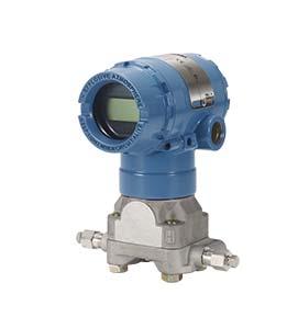
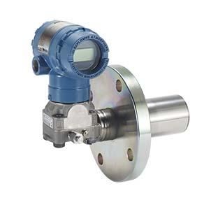

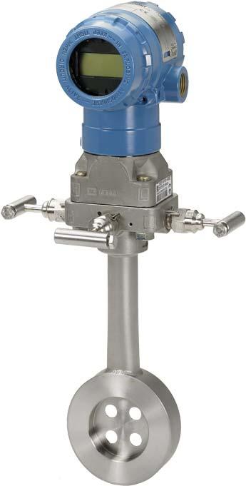
1 Quick Start Guide , Rev AD Rosemount 2051 Pressure Transmitter and Rosemount 2051CF Series Flowmeter with PROFIBUS PA Protocol
2 Quick Start Guide NOTICE This installation guide provides basic guidelines for Rosemount 2051 Transmitters. It does not provide instructions for configuration, diagnostics, maintenance, service, troubleshooting, Explosion-proof, Flame proof, or intrinsically safe (I.S.) installations. Refer to the Rosemount 2051 PROFIBUS PA Reference Manual for more instruction. This manual is also available electronically on EmersonProcess.com/Rosemount. Explosions could result in death or serious injury. Installation of this transmitter in an explosive environment must be in accordance with the appropriate local, national, and international standards, codes, and practices. Review the approvals section of the Rosemount 2051 PROFIBUS PA Reference Manual for any restrictions associated with a safe installation. In an Explosion-proof/Flameproof installation, do not remove the transmitter covers when power is applied to the unit. Process leaks may cause harm or result in death. To avoid process leaks, only use the O-ring designed to seal with the corresponding flange adapter. Electrical shock can result in death or serious injury. Avoid contact with the leads and the terminals. High voltage that may be present on leads can cause electrical shock. Conduit/cable entries Unless marked, the conduit/cable entries in the transmitter housing use a 1 /2 14 NPT thread form. Only use plugs, adapters, glands, or conduit with a compatible thread form when closing these entries. Contents Mount the transmitter Consider housing rotation Set jumpers and switches Connect wiring and power up Basic configuration Trim the transmitter Product Certifications
3 Quick Start Guide 1.0 Mount the transmitter 1.1 Liquid applications 1. Place taps to the side of the line. 2. Mount beside or below the taps. 3. Mount the transmitter so the drain/vent valves are oriented upward. Flow 1.2 Gas applications 1. Place taps in the top or side of the line. 2. Mount beside or above the taps. Flow 1.3 Steam applications 1. Place taps to the side of the line. 2. Mount beside or below the taps. 3. Fill impulse lines with water. Flow 3
4 Quick Start Guide Figure 1. Mounting Options Panel mount (1) Rosemount 2051C Coplanar flange Pipe mount Traditional flange Rosemount 2051T 1. Panel bolts are customer supplied. 4
5 Quick Start Guide 1.4 Bolting considerations If the transmitter installation requires assembly of the process flanges, manifolds, or flange adapters, follow these assembly guidelines to ensure a tight seal for optimal performance characteristics of the transmitters. Use only bolts supplied with the transmitter or sold by Emerson as spare parts. Figure 2 illustrates common transmitter assemblies with the bolt length required for proper transmitter assembly. Figure 2. Common Transmitter Assemblies A C D in. (57 mm) in. (44 mm) B in. (44 mm) in. (38 mm) in. (44 mm) in. (73 mm) A. Transmitter with coplanar flange B. Transmitter with coplanar flange and optional flange adapters C. Transmitter with traditional flange and optional flange adapters D. Transmitter with coplanar flange and optional manifold and flange adapters Bolts are typically carbon steel or stainless steel. Confirm the material by viewing the markings on the head of the bolt and referencing Table 1. If bolt material is not shown in Table 1, contact the local Emerson Process Management representative for more information. Use the following bolt installation procedure: 1. Carbon steel bolts do not require lubrication and the stainless steel bolts are coated with a lubricant to ease installation. However, no additional lubricant should be applied when installing either type of bolt. 2. Finger-tighten the bolts. 3. Torque the bolts to the initial torque value using a crossing pattern. See Table 1 for initial torque value. 4. Torque the bolts to the final torque value using the same crossing pattern. See Table 1 for final torque value. 5. Verify that the flange bolts are protruding through the isolator plate before applying pressure. 5
6 Quick Start Guide Table 1. Torque Values for the Flange and Flange Adapter Bolts Bolt material Head markings Initial torque Final torque Carbon Steel (CS) B7M 300 in-lb 650 in-lb 1.5 O-rings with flange adapters 316 Stainless Steel (SST) 150 in-lb 300 in-lb 316 R B8M STM SW 316 Failure to install proper flange adapter O-rings may cause process leaks, which can result in death or serious injury. The two flange adapters are distinguished by unique O-ring grooves. Only use the O-ring that is designed for its specific flange adapter, as shown below: Rosemount 3051S/3051/2051 A B C D A. Flange adapter B. O-ring C. PTFE based (profile is square) D. Elastomer (profile is round) Whenever the flanges or adapters are removed, visually inspect the O-rings. Replace them if there are any signs of damage, such as nicks or cuts. If you replace the O-rings, re-torque the flange bolts and alignment screws after installation to compensate for seating of the PTFE O-ring. 6
7 Quick Start Guide 1.6 Environmental seal for housing Thread sealing (PTFE) tape or paste on male threads of conduit is required to provide a water/dust tight conduit seal and meets requirements of NEMA Type 4X, IP66, and IP68. Consult factory if other Ingress Protection ratings are required. For M20 threads, install conduit plugs to full thread engagement or until mechanical resistance is met. 1.7 In-line gage transmitter orientation The low side pressure port (atmospheric reference) on the in-line gage transmitter is located in the neck of the transmitter, behind the housing. The vent path is 360 around the transmitter between the housing and sensor. (See Figure 3.) Keep the vent path free of any obstruction, including but not limited to paint, dust, and lubrication by mounting the transmitter so that the process can drain away. Figure 3. In-line Gage Low Side Pressure Port A A. Low side pressure port (atmospheric reference) 2.0 Consider housing rotation To improve field access to wiring or to better view the optional LCD display: 1. Loosen the housing rotation set screw. 2. First rotate the housing clockwise to the desired location. If the desired location cannot be achieved due to thread limit, rotate the housing counter clockwise to the desired location (up to 360 from thread limit). 3. Retighten the housing rotation set screw. Figure 4. Transmitter Housing Set Screw A A. Housing rotation set screw ( 5 /64-in.) 7
8 Quick Start Guide 3.0 Set jumpers and switches 3.1 Security After the transmitter is configured, you may want to protect the configuration data from unwarranted changes. Each transmitter is equipped with a security jumper that can be positioned ON to prevent the accidental or deliberate change of configuration data. The jumper is labeled Security. The security jumper also prevents changes made using the Local Operator Interface. 3.2 Simulate The simulate jumper is used in conjunction with the analog input (AI) block. This jumper is used to simulate the pressure measurement and is used as a lock-out feature for the AI block. To enable the simulate feature, the jumper must be moved to the ON position after power is applied. This feature prevents the transmitter from being accidentally left in simulate mode. Figure 5. Transmitter Jumper Locations ROSEMOUNT 2051 PROFIBUS PA OUTPUT 4.0 Connect wiring and power up Use the following steps to wire the transmitter: 1. Remove the housing cover on the field terminals side. 2. Connect the power leads to the terminals indicated on the terminal block label. Power terminals are polarity insensitive - connect positive or negative to either terminal 3. Ensure full contact with Terminal Block screw and washer. When using a direct wiring method, wrap wire clockwise to ensure it is in place when tightening the terminal block screw. Note The use of a pin or a ferrule wire terminal is not recommended as the connection may be more susceptible to loosening over time or under vibration. 8
9 Quick Start Guide 4. Ensure proper grounding. It is important that the instrument cable shield: Be trimmed close and insulated from touching the transmitter housing Be connected to the next shield if cable is routed through a junction box Be connected to a good earth ground at the power supply end 5. Plug and seal unused conduit connections. 6. If applicable, install wiring with a drip loop. Arrange the drip loop so the bottom is lower than the conduit connections and the transmitter housing. 7. Replace the housing cover. Figure 6. Terminals B A A. Power terminals B. Ground terminal 9
10 Quick Start Guide Figure 7. Wiring A B C D E F G H I I A ft (1900 m) max (depending on cable characteristics) B. Integrated power conditioner and filter C. Terminators D. Power supply E. DP/PA coupler/link F. Trunk G. DP network H. Signal wiring I. Spur J. PROFIBUS PA device J 4.1 Signal wiring grounding Do not run signal wiring in conduit or open trays with power wiring, or near heavy electrical equipment. Grounding terminations are provided on the outside of the electronics housing and inside the terminal compartment. These grounds are used when transient protect terminal blocks are installed or to fulfill local regulations. See Step 2 below for more information on how the cable shield should be grounded. 1. Remove the field terminals housing cover. 2. Connect the wiring pair and ground as indicated in Figure 8. The cable shield should: Be trimmed close and insulated from touching the transmitter housing. Continuously connect to the termination point. Be connected to a good earth ground at the power supply end. 10
11 DP Quick Start Guide Figure 8. Wiring A C B A. Trim shield and insulate B. Insulate shield C. Connect shield back to the power supply ground 3. Replace the housing cover. It is recommended that the cover be tightened until there is no gap between the cover and the housing. 4. Plug and seal unused conduit connections. Power supply The dc power supply should provide power with less than two percent ripple. The transmitter requires between 9 and 32 Vdc at the terminals to operate and provide complete functionality. Power conditioner The DP/PA coupler/link often includes an integrated power conditioner. Grounding Transmitters are electrically isolated to 500 Vac rms. Signal wiring can not be grounded. Shield wire ground Shield wire usually requires a single grounding point to avoid creating a ground loop. The ground point is typically at the power supply. 5.0 Basic configuration 5.1 Configuration tasks The transmitter can be configured via either the local operator interface (LOI) option code M4, or via a Class 2 master (DD or DTM based). The two basic configuration tasks for the PROFIBUS PA Pressure transmitter are: 1. Assign address. 2. Configure engineering units (scaling). 11
12 Quick Start Guide Note Rosemount 2051 PROFIBUS PA Profile 3.02 devices are set to identification number adaptation mode when shipped from the factory. This mode allows the transmitter to communicate with any PROFIBUS PA control host with either the generic Profile GSD (9700) or Rosemount 2051 specific GSD (3333) loaded on the host; therefore, it is not required to change the transmitter identification number at startup. Assign address The Rosemount 2051 Pressure Transmitter is shipped with a temporary address of 126. This must be changed to a unique value between 0 and 125 in order to establish communication with the host. Usually, addresses 0 2 are reserved for masters or couplers, therefore transmitter addresses between 3 and 125 are recommended. Address can be set via either: LOI see Table 2 and Figure 9 Class 2 master see Class 2 Master Manual for setting address Configure engineering units Unless otherwise requested, the Rosemount 2051 Pressure Transmitter ships with the following settings: Measurement mode: Pressure Engineering units: inches H 2 O Scaling: None Engineering units should be confirmed or configured before installation. Units can be configured for Pressure, Flow, or Level measurement. Measurement type, Units, Scaling, and Low Flow Cutoff (when applicable) can be set via either: LOI see Table 2 and Figure 9 Class 2 master see Table 3 for parameter configuration 12
13 Quick Start Guide 5.2 Configuration tools Local operator interface (LOI) When ordered, the LOI can be used for commissioning the device. To activate the LOI, push either configuration button located under the top tag of the transmitter. See Table 2 and Figure 9 for operation and menu information. The security jumper prevents changes made using the LOI. Note Buttons must be fully engaged 0.5-in. (10 mm) of travel. Table 2. LOI Button Operation Button Action Navigation Character Entry Save? Scroll Moves down menu categories Changes character value (1) Changes between Save and Cancel Enter Selects menu category Enters character and advances Saves 1. Characters blink when they can be changed. Figure 9. LOI Menu 1. ADDRESS 2. CALIBRATION 3. UNITS 4. DAMPING 5. DISPLAY 6. IDENTIFICATION # 7. EXIT PRESSURE FLOW LEVEL TEMPERATURE ZERO LOWER SENSOR UPPER SENSOR RESET FACTORY
14 Quick Start Guide 5.3 Class 2 Master The Rosemount 2051 PROFIBUS DD and DTM files are available at EmersonProcess.com/Rosemount or by contacting your local salesperson. See Table 3 for steps to configure the transmitter for Pressure measurement. See Rosemount 2051 Reference Manual for Flow or Level configuration instructions. Table 3. Pressure Configuration via Class 2 Master Steps Set blocks to Out of Service Select Measurement Type Select Units 5.4 Host integration Control host (Class 1) The Rosemount 2051 device utilizes condensed status as recommended by the Profile 3.02 specification and NE 107. See manual for condensed status bit assignment information. The appropriate GSD file must be loaded on the control host - Rosemount 2051 specific (rmt3333.gsd) or Profile 3.02 Generic (pa gsd). These files can be found on EmersonProcess.com/Rosemount or Profibus.com. Configuration host (Class 2) Actions Put Transducer Block into Out of Service mode Put Analog Input Block into Out of Service mode Set Primary Value type to Pressure Set Engineering Units - Primary and secondary units must match Enter Scaling Set Scale In in Transducer Block to Set blocks to Auto Set Scale Out in Transducer Block to Set PV Scale in Analog Input Block to Set Out Scale in Analog Input Block to Set Linearization in Analog Input Block to No Linearization Put Transducer Block into Auto mode Put Analog Input Block into Auto mode The appropriate DD or DTM file must be installed in the configuration host. These files can be found at EmersonProcess.com/Rosemount. 14
15 Quick Start Guide 6.0 Trim the transmitter Devices are calibrated by the factory. Once installed, it is recommended to perform a zero trim on the sensor to eliminate error due to mounting position or static pressure effects. This can be done by performing a zero trim via: LOI see Table 1 and Figure 9 Class 2 master see Zero trim via Class 2 Master for parameter settings 6.1 Zero trim via Class 2 Master 1. Place the transducer block into Out of Service (OOS) mode. 2. Apply zero pressure to device and allow to stabilize. 3. Go to Basic Setup > Calibration and set the lower calibration point to Place the transducer block to AUTO mode. 15
16 Quick Start Guide 7.0 Product Certifications Rev European Directive Information A copy of the EC Declaration of Conformity can be found at the end of the Quick Start Guide. The most recent revision of the EC Declaration of Conformity can be found at EmersonProcess.com/Rosemount. 7.2 Ordinary Location Certification As standard, the transmitter has been examined and tested to determine that the design meets the basic electrical, mechanical, and fire protection requirements by a nationally recognized test laboratory (NRTL) as accredited by the Federal Occupational Safety and Health Administration (OSHA). 7.3 North America E5 USA Explosionproof (XP) and Dust-Ignitionproof (DIP) Certificate: FM16US0232 Standards: FM Class , FM Class , FM Class , FM Class , ANSI/NEMA ANSI/IEC Markings: XP CL I, DIV 1, GP B, C, D; DIP CL II, DIV 1, GP E, F, G; CL III; T5 ( 50 C T a +85 C); Factory Sealed; Type 4X I5 USA Intrinsic Safety (IS) and Nonincendive (NI) Certificate: FM16US0231X Standards: FM Class , FM Class , FM Class , FM Class , ANSI/NEMA Markings: IS CL I, DIV 1, GP A, B, C, D; CL II, DIV 1, GP E, F, G; Class III; DIV 1 when connected per Rosemount drawing ; Class I, Zone 0; AEx ia IIC T4; NI CL 1, DIV 2, GP A, B, C, D; T4( 50 C T a +70 C); Type 4x Specific Condition of Use (X): 1. The Model 2051 transmitter housing contains aluminum and is considered a potential risk of ignition by impact or friction. Care must be taken into account during installation and use to prevent impact and friction. IE USA FISCO Certificate: FM16US0231X Standards: FM Class , FM Class , FM Class , FM Class Markings: IS CL I, DIV 1, GP A, B, C, D when connected per Rosemount drawing ( 50 C T a +60 C); Type 4x Specific Condition of Use (X): 1. The Model 2051 transmitter housing contains aluminum and is considered a potential risk of ignition by impact or friction. Care must be taken into account during installation and use to prevent impact and friction. 16
17 Quick Start Guide E6 I6 7.4 Europe Canada Explosion-Proof, Dust Ignition Proof Certificate: Standards: CAN/CSA C22.2 No. 0-10, CSA Std C22.2 No , CSA Std C22.2 No. 30-M1986, CAN/CSA-C22.2 No. 94-M91, CSA Std C22.2 No.142-M1987, CAN/CSA-C22.2 No , CSA Std C22.2 No. 213-M1987, CAN/CSA-E :07, CAN/CSA-E :07, CAN/CSA-E , CAN/CSA-C22.2 No :05, ANSI/ISA Markings: Explosion-Proof for Class I, Divisions 1, Groups B, C, and D. Dust-Ignition Proof for Class II and Class III, Division 1, Groups E, F, and G. Suitable for Class I, Division 2; Groups A, B, C, and D for indoor and outdoor hazardous locations. Class I Zone 1 Ex d IIC T5. Enclosure type 4X, factory sealed. Single Seal. Canada Intrinsic Safety Certificate: Standards: CSA Std. C22.2 No M1987, CSA Std. C22.2 No M1987, CSA Std. C22.2 No , CSA Std. C22.2 No M1987, ANSI/ISA , CAN/CSA-E :07, CAN/CSA-E :02 Markings: Intrinsically safe for Class I, Division 1, Groups A, B, C, and D when connected in accordance with Rosemount drawing Ex ia IIC T3C. Single Seal. Enclosure Type 4X E1 ATEX Flameproof Certificate: KEMA 08ATEX0090X Standards: EN :2006, EN :2007, EN :2007 Markings: II 1/2 G Ex d IIC T6 IP66 ( 50 C T a +65 C) II 1/2 G Ex d IIC T5 IP66 ( 50 C T a +80 C) Special Conditions for Safe Use (X): 1. The Ex d blanking elements, cable glands and wiring needs to be suitable for a temperature of 90 C. 2. This device contains a thin wall diaphragm. Installation, maintenance and use shall take into account the environmental conditions to which the diaphragm will be subjected. The manufacturer s instructions for maintenance shall be followed in detail to assure safety during its expected lifetime. 3. In case of repair, contact the manufacturer for information on the dimensions of the flameproof joints. I1 ATEX Intrinsic Safety Certificate: Baseefa08ATEX0129X Standards: EN :2012, EN :2012 Markings: II 1 G Ex ia IIC T4 Ga ( 60 C Ta +70 C) Table 4. Input Parameters Parameter HART Fieldbus/PROFIBUS Voltage U i 30 V 30 V Current I i 200 ma 300 ma Power P i 1 W 1.3 W Capacitance C i μf 0 μf Inductance L i 0 mh 0 mh 17
18 Quick Start Guide Special Conditions for Safe Use (X): 1. If the equipment is fitted with an optional 90 V transient suppressor, it is incapable of withstanding the 500 V isolation from earth test and this must be taken into account during installation. 2. The enclosure may be made of aluminum alloy and given a protective polyurethane paint finish; however care should be taken to protect it from impact and abrasion when located in Zone 0. IA ATEX FISCO Certificate: Baseefa08ATEX0129X Markings: II 1 G Ex ia IIC T4 Ga ( 60 C T a +60 C) Table 5. Input Parameters Parameter Voltage U i Current I i Power P i Capacitance C i Inductance L i FISCO 17.5 V 380 ma 5.32 W 0 μf 0 mh Special Conditions for Safe Use (X): 1. If the equipment is fitted with an optional 90 V transient suppressor, it is incapable of withstanding the 500 V isolation from earth test and this must be taken into account during installation. 2. The enclosure may be made of aluminum alloy and given a protective polyurethane paint finish; however care should be taken to protect it from impact and abrasion when located in Zone 0. N1 ATEX Type n Certificate: Baseefa08ATEX0130X Standards: EN :2012, EN :2010 Markings: II 3 G Ex na IIC T4 Gc ( 40 C T a +70 C) Special Condition for Safe Use (X): 1. If the equipment is fitted with an optional 90 V transient suppressor, it is incapable of withstanding the 500 V electrical strength test as defined in clause of by EN :2010. This must be taken into account during installation. ND ATEX Dust Certificate: Baseefa08ATEX0182X Standards: EN :2012, EN :2009 Markings: II 1 D Ex ta IIIC T95 C T C Da ( 20 C T a +85 C) Special Condition for Safe Use (X): 1. If the equipment is fitted with an optional 90 V transient suppressor, it is incapable of withstanding the 500 V isolation from earth test and this must be taken into account during installation. 7.5 International E7 IECEx Flameproof Certificate: IECExKEM X Standards: IEC :2004, IEC : , IEC :
19 Quick Start Guide Markings: Ex d IIC T6/T5 IP66, T6( 50 C T a +65 C), T5( 50 C T a +80 C) Table 6. Process Temperature Temperature class Process temperature Special Conditions for Safe Use (X): 1. The device contains a thin wall diaphragm. Installation, maintenance and use shall take into account the environmental conditions to which the diaphragm will be subjected. The manufacturer s instructions for maintenance shall be followed in detail to assure safety during its expected lifetime. 2. The Ex d blanking elements, cable glands, and wiring shall be suitable for a temperature of 90 C. 3. In case of repair, contact the manufacturer for information on the dimensions of the flameproof joints. I7 IECEx Intrinsic Safety Certificate: IECExBAS X Standards: IEC :2011, IEC :2011 Markings: Ex ia IIC T4 Ga ( 60 C T a +70 C) Special Conditions for Safe Use (X): 1. If the equipment is fitted with an optional 90 V transient suppressor, it is incapable of withstanding the 500 V isolation from earth test and this must be taken into account during installation. 2. The enclosure may be made of aluminum alloy and given a protective polyurethane paint finish; however care should be taken to protect it from impact and abrasion when located in Zone 0. IG T6 50 C to +65 C T5 50 C to +80 C Table 7. Input Parameters Parameter HART Fieldbus/PROFIBUS Voltage U i 30 V 30 V Current I i 200 ma 300 ma Power P i 1 W 1.3 W Capacitance C i μf 0 μf Inductance L i 0 mh 0 mh IECEx FISCO Certificate: IECExBAS X Standards: IEC :2011, IEC :2011 Markings: Ex ia IIC T4 Ga ( 60 C T a +60 C) Table 8. Input Parameters Parameter Voltage U i Current I i Power P i Capacitance C i FISCO 17.5 V 380 ma 5.32 W 0 μf 19
20 Quick Start Guide Table 8. Input Parameters Parameter Inductance L i FISCO 0 mh Special Conditions for Safe Use (X): 1. If the equipment is fitted with an optional 90 V transient suppressor, it is incapable of withstanding the 500 V isolation from earth test and this must be taken into account during installation. 2. The enclosure may be made of aluminum alloy and given a protective polyurethane paint finish; however care should be taken to protect it from impact and abrasion when located in Zone 0. N7 IECEx Type n Certificate: IECExBAS X Standards: IEC :2011, IEC :2010 Markings: Ex na IIC T4 Gc ( 40 C T a +70 C) Special Condition for Safe Use (X): 1. If fitted with a 90 V transient suppressor, the equipment is not capable of withstanding the 500 V electrical strength test as defined in clause of IEC :2010. This must be taken into account during installation. 7.6 Brazil E2 INMETRO Flameproof Certificate: UL-BR X Standards: ABNT NBR IEC : Errata 1:2011, ABNT NBR IEC : Errata 1:2011, ABNT NBR IEC : Errata 1:2009 Markings: Ex d IIC T6/T5 Gb IP66, T6( 50 C T a +65 C), ( 50 C T a +80 C) Special Conditions for Safe Use (X): 1. The device contains a thin wall diaphragm. Installation, maintenance and use shall take into account the environmental conditions to which the diaphragm will be subjected. The manufacturer s instructions for installation and maintenance shall be followed in detail to assure safety during its expected lifetime. 2. The Ex d blanking elements, cable glands, and wiring shall be suitable for a temperature of 90 C. 3. In case of repair, contact the manufacturer for information on the dimensions of the flameproof joints. I2 INMETRO Intrinsic Safety Certificate: UL-BR X Standards: ABNT NBR IEC : Errata 1:2011; ABNT NBR IEC :2009 Markings: Ex ia IIC T4 Ga ( 60 C T a +70 C) Table 9. Input Parameters Parameter HART Fieldbus/PROFIBUS Voltage U i 30 V 30 V Current I i 200 ma 300 ma Power P i 1 W 1.3 W Capacitance C i 12 nf 0 20
21 Quick Start Guide Special Conditions for Safe Use (X): 1. If the equipment is fitted with an optional 90 V transient suppressor, it is incapable of withstanding the 500 V insulation from earth test and this must be taken into account during installation. 2. The enclosure may be made of aluminium alloy and given a protective polyurethane paint finish; however care should be taken to protect it from impact and abrasion when located in atmospheres that require ELP Ga. IB Table 9. Input Parameters Parameter HART Fieldbus/PROFIBUS Inductance L i 0 0 INMETRO FISCO Certificate: UL-BR X Standards: ABNT NBR IEC : Errata 1:2011; ABNT NBR IEC :2009 Markings: Ex ia IIC T4 Ga ( 60 C T a +60 C) Table 10. Input Parameters Parameter Voltage U i Current I i Power P i Capacitance C i Inductance L i FISCO 17.5 V 380 ma 5.32 W 0 nf 0 μh Special Conditions for Safe Use (X): 1. If the equipment is fitted with an optional 90 V transient suppressor, it is incapable of withstanding the 500 V insulation from earth test and this must be taken into account during installation. 2. The enclosure may be made of aluminium alloy and given a protective polyurethane paint finish; however care should be taken to protect it from impact and abrasion when located in atmospheres that require ELP Ga. 7.7 China E3 China Flameproof Certificate: GYJ X; GYJ X [Flowmeters] Standards: GB , GB , GB Markings: Pressure Transmitter: Ex d IIC Gb, T6( 50 C T a +65 C), T5( 50 C T a +80 C) Flowmeter: Ex d IIC Ga/Gb, T6( 50 C T a +65 C), T5( 50 C T a +80 C) Special Conditions for Safe Use (X): 1. Symbol X is used to denote specific conditions of use: a. The Ex d blanking elements, cable glands, and wiring shall be suitable for a temperature of 90 C. b. This device contains a thin wall diaphragm. Installation, maintenance and use shall take into account the environment conditions to which the diaphragm will be subjected. 21
22 Quick Start Guide 2. The relation between T code and ambient temperature range is: T a Temperature class 50 C T a +80 C T5 50 C T a +65 C T6 3. The earth connection facility in the enclosure should be connected reliably. 4. During installation, use and maintenance of the product, observe the warning Don t open the cover when the circuit is alive. 5. During installation, there should be no mixture harmful to flameproof housing 6. Cable entry and conduit, certified by NEPSI with type of protection Ex d IIC Gb and appropriate thread form, should be applied when installed in a hazardous location. Blanking elements should be used on the redundant cable entries. 7. End users are not permitted to change any internal components, but to settle the problem in conjunction with the manufacturer to avoid damage to the product. 8. Maintenance should be done in a non-hazardous location. 9. During installation, use and maintenance of this product, observe the following standards: GB , GB , GB , GB E3 China Intrinsic Safety Certificate: GYJ X; GYJ X [Flowmeters] Standards: GB , GB , GB Markings: Ex ia IIC T4 Ga ( 60 C T a +70 C) Special Conditions for Safe Use (X): 1. Symbol X is used to denote specific conditions of use: a. The Ex d blanking elements, cable glands, and wiring shall be suitable for a temperature of 90 C. b. This device contains a thin wall diaphragm. Installation, maintenance and use shall take into account the environment conditions to which the diaphragm will be subjected. 2. The relation between T code and ambient temperature range is: Model T code Temperature range HART, Fieldbus, PROFIBUS, and Low Power T4 60 C T a +70 C 3. Intrinsically Safe parameters: Parameter HART Fieldbus/PROFIBUS Voltage U i 30 V 30 V Current I i 200 ma 300 ma Power P i 1 W 1.3 W Capacitance C i μf 0 μf Inductance L i 0 mh 0 mh Note 1: FISCO parameters comply with the requirements for FISCO field devices in GB Note 2: [For Flowmeters] When Rosemount 644 Temperature Transmitter is used, the Rosemount 644 should be used with Ex-certified associated apparatus to establish explosion protection system that can be used in explosive gas atmospheres. Wiring and terminals should comply with the instruction manual of both Rosemount 644 and associated apparatus. The cables between Rosemount 644 and associated apparatus 22
23 Quick Start Guide should be shielded cables (the cables must have insulated shield). The shielded cable has to be grounded reliably in a non-hazardous area. 4. The product should be used with Ex-certified associated apparatus to establish explosion protection system that can be used in explosive gas atmospheres. Wiring and terminals should comply with the instruction manual of the product and associated apparatus. 5. The cables between this product and associated apparatus should be shielded cables (the cables must have insulated shield). The shielded cable has to be grounded reliably in a non-hazardous area. 6. End users are not permitted to change any internal components, and needs to settle the problem in conjunction with the manufacturer to avoid damage to the product. 7. During installation, use and maintenance of this product, observe the following standards: GB , GB , GB , GB , GB Japan E4 Japan Flameproof Certificate: TC20598, TC20599, TC20602, TC20603 [HART]; TC20600, TC20601, TC20604, TC20605 [Fieldbus] Markings: Ex d IIC T5 7.9 Technical Regulations Customs Union (EAC) EM EAC Flameproof Certificate: RU C-US.GB05.B Markings: Ga/Gb Ex d IIC X, T5( 50 C T a +80 C), T6( 50 C T a +65 C) Special Condition for Safe Use (X): 1. See certificate for special conditions. IM EAC Intrinsically Safe Certificate: RU C-US.GB05.B Markings: 0Ex ia IIC T4 Ga X ( 60 C T a +70 C) Special Condition for Safe Use (X): 1. See certificate for special conditions Combinations K1 Combination of E1, I1, N1, and ND K2 Combination of E2 and I2 K5 Combination of E5 and I5 K6 Combination of E6 and I6 K7 Combination of E7, I7, N7, and IECEx Dust IECEx Dust Certificate: IECEx BAS X Standards: IEC :2011, IEC :2008 Markings: Ex ta IIIC T95 C T C Da ( 20 C T a +85 C) Special Condition for Safe Use (X): 1. If the equipment is fitted with an optional 90 V transient suppressor, it is incapable of withstanding a 500 V isolation from earth test and this must be taken into account during installation. KA Combination of E1, I1, and K6 23
24 Quick Start Guide KB Combination of K5 and K6 KC Combination of E1, I1, and K5 KD Combination of K1, K5, and K6 KM Combination of EM and IM 7.11 Additional Certifications SBS American Bureau of Shipping (ABS) Type Approval Certificate: 09-HS446883B-3-PDA Intended Use: Marine & Offshore Applications Measurement of either Gauge or Absolute Pressure for Liquid, Gas, and Vapor. ABS Rules: 2013 Steel Vessels Rules 1-1-4/7.7, 1-1-Appendix 3, 4-8-3/1.7, 4-8-3/13.1 SBV Bureau Veritas (BV) Type Approval Certificate: 23157/B0 BV BV Rules: Bureau Veritas Rules for the Classification of Steel Ships Application: Class notations: AUT-UMS, AUT-CCS, AUT-PORT and AUT-IMS; Pressure transmitter type 2051 cannot be installed on diesel engines SDN Det Norske Veritas (DNV) Type Approval Certificate: TAA000004F Intended Use: DNV GL Rules for Classification - Ships and offshore units Application: Location classes Type 2051 Temperature Humidity Vibration EMC Enclosure D B A B D SLL Lloyds Register (LR) Type Approval Certificate: 11/60002 Application: Environmental categories ENV1, ENV2, ENV3, and ENV5 24

25 Quick Start Guide Figure 10. Rosemount 2051 EC Declaration of Conformity 25

26 Quick Start Guide 26

27 Quick Start Guide 27

28 Quick Start Guide 28
29 Quick Start Guide China RoHS Rosemount 2051 List of Rosemount 2051 Parts with China RoHS Concentration above MCVs / Hazardous Substances Part Name Lead (Pb) Mercury (Hg) Cadmium (Cd) Hexavalent Chromium (Cr +6) Polybrominated biphenyls (PBB) Polybrominated diphenyl ethers (PBDE) Electronics Assembly X O O O O O Housing Assembly X O O X O O Sensor Assembly X O O X O O SJ/T11364 This table is proposed in accordance with the provision of SJ/T O: GB/T O: Indicate that said hazardous substance in all of the homogeneous materials for this part is below the limit requirement of GB/T X: GB/T X: Indicate that said hazardous substance contained in at least one of the homogeneous materials used for this part is above the limit requirement of GB/T
30 * * Quick Start Guide , Rev AD Global Headquarters Emerson Process Management 6021 Innovation Blvd. Shakopee, MN 55379, USA or North America Regional Office Emerson Process Management 8200 Market Blvd. Chanhassen, MN 55317, USA or Latin America Regional Office Emerson Process Management 1300 Concord Terrace, Suite 400 Sunrise, FL 33323, USA Europe Regional Office Emerson Process Management Europe GmbH Neuhofstrasse 19a P.O. Box 1046 CH 6340 Baar Switzerland +41 (0) (0) Asia Pacific Regional Office Emerson Process Management Asia Pacific Pte Ltd 1 Pandan Crescent Singapore Enquiries@AP.EmersonProcess.com Middle East and Africa Regional Office Emerson Process Management Emerson FZE P.O. Box 17033, Jebel Ali Free Zone - South 2 Dubai, United Arab Emirates RFQ.RMTMEA@Emerson.com Linkedin.com/company/Emerson-Process-Management Twitter.com/Rosemount_News Facebook.com/Rosemount Youtube.com/user/RosemountMeasurement Google.com/+RosemountMeasurement Standard Terms and Conditions of Sale can be found at The Emerson logo is a trademark and service mark of Emerson Electric Co. Rosemount and Rosemount logotype are trademarks of Emerson Process Management. PROFIBUS is a registered trademark of PROFINET International (PI). DTM is a trademark of the FDT Group. FOUNDATION Fieldbus is a trademark of the FieldComm Group. All other marks are the property of their respective owners Emerson Process Management. All rights reserved.
Rosemount 0085 Pipe Clamp Sensor Assembly. Quick Start Guide , Rev CA June 2016
 Rosemount 0085 Pipe Clamp Sensor Assembly 00825-0100-4952, Rev CA NOTICE This guide provides basic guidelines for Rosemount 0085 Pipe Clamp Sensor. It does not provide instructions for configuration, diagnostics,
Rosemount 3051 Pressure Transmitter and Rosemount 3051CF Series Flowmeter
 Quick Start Guide 00825-0100-4797, Rev ED Rosemount 3051 Pressure Transmitter and Rosemount 3051CF Series Flowmeter with PROFIBUS PA Protocol Quick Start Guide NOTICE This installation guide provides basic
Rosemount 148 Temperature Transmitter. Quick Start Guide , Rev GA September 2016
 Rosemount 148 Temperature Transmitter 00825-0100-4148, Rev GA NOTICE This guide provides basic guidelines for the Rosemount 148. It does not provide instructions for detailed configuration, diagnostics,
Rosemount 214C Sensor. Quick Start Guide , Rev AF August 2017
 Rosemount 214C Sensor 00825-0400-2654, Rev AF NOTICE This guide provides basic guidelines for Rosemount 214C Sensor models. If the sensor was ordered assembled to a temperature thermowell or transmitter,
Rosemount 3490 Series 4 20 ma + HART Compatible Controller
 00825-0200-4841, Rev AB Rosemount 3490 Series 4 20 ma + HART Compatible Controller Failure to follow safe installation guidelines could result in death or serious injury The Rosemount 3490 Series Control
Rosemount 3051S MultiVariable Transmitter Rosemount 3051SF Series MultiVariable Flowmeter
 Quick Start Guide 00825-0100-4853, Rev AD Rosemount 3051S MultiVariable Transmitter Rosemount 3051SF Series MultiVariable Flowmeter with FOUNDATION Fieldbus Protocol Quick Start Guide NOTICE This guide
Quick Start Guide , Rev EA December Rosemount 0065/0185 Sensor Assembly
 Quick Start Guide 00825-0200-2654, Rev EA Rosemount 0065/0185 Sensor Assembly Quick Start Guide NOTICE This guide provides basic guidelines for Rosemount 0065 and 0185 Sensor models. It does not provide
Rosemount 752 FOUNDATION Fieldbus Remote Indicator
 Rosemount 752 FOUNDATION Fieldbus Remote Indicator Product Data Sheet 00813-0100-4377, Rev FA Two-wire segment powered device Displays up to eight values Link Master Capability Optional PID, Characterizer,
Rosemount 4600 Oil & Gas Panel Pressure Transmitter. Quick Start Guide , Rev GA September 2017
 Rosemount 4600 Oil & Gas Panel Pressure Transmitter 00825-0100-4022, Rev GA NOTICE NOTICE This guide provides basic guidelines for the Rosemount 4600 Oil & Gas Panel Pressure Transmitter. It does not provide
Rosemount 0085 Pipe Clamp Sensor Assembly. Quick Start Guide , Rev DC August 2017
 Rosemount 0085 Pipe Clamp Sensor Assembly Quick Start Guide 00825-0100-4952, Rev DC Quick Start Guide NOTICE This guide provides basic guidelines for Rosemount 0085 Pipe Clamp Sensor. It does not provide
Rosemount 752 Remote Indicator
 Quick Start Guide 00825-0100-4377, Rev EA Rosemount 752 Remote Indicator with FOUNDATION Fieldbus Protocol Quick Start Guide This guide provides basic guidelines for Rosemount 752 Remote Indicator. It
Rosemount 2090F Hygienic Pressure Transmitter
 Rosemount 2090F Hygienic Pressure Transmitter Product Data Sheet November 2016 00813-0100-4698, Rev FC Conforms to 3-A Sanitary Standards Features CIP/SIP service for process temperatures up to 284 F (140
Quick Start Guide , Rev CB May Rosemount 3144P Temperature Transmitters with FOUNDATION fieldbus Protocol
 Quick Start Guide 00825-0100-4834, Rev CB Rosemount 3144P Temperature Transmitters with FOUNDATION fieldbus Protocol Quick Start Guide NOTICE NOTICE This guide provides basic guidelines for the Rosemount
Quick Start Guide , Rev DA December Rosemount Volume 1 Sensor Assembly
 Quick Start Guide 00825-0300-2654, Rev DA Rosemount Volume 1 Sensor Assembly Quick Start Guide NOTICE This guide provides basic guidelines for Rosemount 0068, 0078, and 0183 Sensor models. It does not
Rosemount 2051 Pressure Transmitter with 4-20 ma HART and 1-5 Vdc HART Low Power Protocol
 Quick Installation Guide August 2009 Rosemount 2051 Rosemount 2051 Pressure Transmitter with 4-20 ma HART and 1-5 Vdc HART Low Power Protocol Start Step 1: Mount the Transmitter Step 2: Consider Housing
Rosemount 3144P Temperature Transmitters with FOUNDATION Fieldbus Protocol. Quick Start Guide , Rev DA June 2016
 Rosemount 3144P Temperature Transmitters with FOUNDATION Fieldbus Protocol 00825-0100-4834, Rev DA NOTICE This guide provides basic guidelines for Rosemount 3144P. It does not provide instructions for
Rosemount 2088, 2090P, and 2090F Pressure Transmitters
 Quick Start Guide 00825-0100-4690, Rev FD Rosemount 2088, 2090P, and 2090F Pressure Transmitters with 4 20 ma HART and 1 5 Vdc HART Low Power Protocol Quick Start Guide NOTICE This installation guide provides
Rosemount 3051 Pressure Transmitter
 Quick Start Guide 00825-0100-4001, rev. JA Rosemount 3051 Pressure Transmitter with 4-20 ma HART and 1-5 Vdc Low Power Protocol Rosemount 3051CF Series Flowmeter Transmitter with 4-20 ma HART and 1-5 Vdc
Rosemount 644H Temperature Transmitters
 Quick Start Guide 00825-0100-4829, Rev DA Rosemount 644H Temperature Transmitters with FOUNDATION Fieldbus Quick Start Guide NOTICE This guide provides basic guidelines for the Rosemount 644. It does not
Rosemount 2090F Hygienic Pressure Transmitter
 Rosemount 2090F Hygienic Pressure Transmitter Product Data Sheet December 2017 00813-0100-4698, Rev GA Conforms to 3-A Sanitary Standards Features CIP/SIP service for process temperatures up to 284 F (140
Annubar Flowmeter Series
 Reference Manual Appendix B Approvals Annubar Flowmeter Series Hazardous Locations Installations.................. page B-1 Rosemount 3051SFA Product Certifications.......... page B-1 Rosemount 3095MFA
Rosemount 644H Temperature Transmitters
 Quick Start Guide 00825-0300-4728, Rev CA Rosemount 644H Temperature Transmitters with PROFIBUS PA Quick Start Guide NOTICE This guide provides basic guidelines for the Rosemount 644. It does not provide
Rosemount 2088, 2090F, and 2090P Pressure Transmitter
 Quick Start Guide 00825-0100-4108, Rev BA Rosemount 2088, 2090F, and 2090P Pressure Transmitter with 4-20 ma HART and 1-5 Vdc Low Power HART Protocol (Revision 5 and 7) Quick Start Guide NOTICE This guide
Rosemount 3051S Series Pressure Transmitter and Rosemount 3051SF Series Flowmeter
 Quick Start Guide 00825-0100-4801, Rev MC Rosemount 3051S Series Pressure Transmitter and Rosemount 3051SF Series Flowmeter with HART Protocol Quick Start Guide NOTICE This guide provides basic guidelines
Rosemount 3051HT Hygienic Pressure Transmitter
 00825-0100-4091, Rev CA Rosemount 3051HT Hygienic Pressure Transmitter with 4 20 ma HART Revision 5 and 7 Protocol Note Before installing the transmitter, confirm the correct device driver is loaded on
Rosemount 2051G Pressure Transmitter
 Quick Start Guide 00825-0700-4101, Rev AB Rosemount 2051G Pressure Transmitter with 4 20 ma HART Protocol (Revision 5 and 7) Quick Start Guide NOTICE This guide provides basic guidelines for Rosemount
SmartPower Solutions. Quick Start Guide , Rev CA March 2015
 SmartPower Solutions 00825-0100-4701, Rev CA NOTICE This guide provides basic guidelines for the SmartPower family of products. It does not provide instructions for detailed configuration, diagnostics,
Rosemount 4600 Oil & Gas Panel Pressure Transmitter
 Product Data Sheet October 2017 00813-0100-4022, Rev LA Rosemount 4600 Oil & Gas Panel Pressure Transmitter A compact, lightweight, all-welded stainless steel design Up to 40:1 rangeability for increased
Quick Start Guide , Rev HA January Rosemount 248 Temperature Transmitter
 00825-0100-4825, Rev HA Rosemount 248 Temperature Transmitter NOTICE This guide provides basic guidelines for the Rosemount 248. It does not provide instructions for detailed configuration, diagnostics,
Rosemount 3051S MultiVariable Transmitter Rosemount 3051SF Series Flowmeter MultiVariable Transmitter
 00825-0100-4803, Rev EE Rosemount 3051S MultiVariable Transmitter Rosemount 3051SF Series Flowmeter MultiVariable Transmitter NOTICE This guide provides basic guidelines for the Rosemount 3051S MultiVariable
Rosemount 644H Temperature Transmitters
 Quick Start Guide 00825-0300-4728, Rev BA Rosemount 644H Temperature Transmitters with PROFIBUS PA Quick Start Guide NOTICE This guide provides basic guidelines for the Rosemount 644. It does not provide
Rosemount 848T FOUNDATION Fieldbus High Density Temperature Transmitter
 Quick Start Guide 00825-0100-4697, Rev SF Rosemount 848T FOUNDATION Fieldbus High Density Temperature Transmitter Device Revision 8 - Requires New DD/CFF Revision Quick Start Guide NOTICE This guide provides
Rosemount 2088, 2090F, and 2090P Pressure Transmitter
 Quick Start Guide 00825-0100-4108, Rev CA Rosemount 2088, 2090F, and 2090P Pressure Transmitter with 4 20 ma HART and 1 5 Vdc Low Power HART Protocol (Revision 5 and 7) Quick Start Guide NOTICE This guide
Quick Start Guide , Rev DA June Rosemount 644H (Device Revision 7 or Previous) and 644R Smart Temperature Transmitters
 and 644R Smart Temperature Transmitters") Quick Start Guide 00825-0100-4728, Rev DA Rosemount 644H (Device Revision 7 or Previous) and 644R Smart Temperature Transmitters Quick Start Guide NOTICE This guide provides basic guidelines for the Rosemount
Quick Start Guide 00825-0100-4728, Rev DA Rosemount 644H (Device Revision 7 or Previous) and 644R Smart Temperature Transmitters Quick Start Guide NOTICE This guide provides basic guidelines for the Rosemount
Rosemount 4088B MultiVariable Transmitter with Bristol Standard Asynchronous/Synchronous Protocol (BSAP)/MVS Protocol
/MVS Protocol") Quick Start Guide 00825-0200-4088, Rev CA Rosemount 4088B MultiVariable Transmitter with Bristol Standard Asynchronous/Synchronous Protocol (BSAP)/MVS Protocol Quick Start Guide NOTICE This installation
Quick Start Guide 00825-0200-4088, Rev CA Rosemount 4088B MultiVariable Transmitter with Bristol Standard Asynchronous/Synchronous Protocol (BSAP)/MVS Protocol Quick Start Guide NOTICE This installation
Rosemount 3144P Temperature Transmitter
 00825-0100-4021, Rev MA Rosemount 3144P Temperature Transmitter with HART Protocol and Rosemount X-well Technology NOTICE This guide provides basic guidelines for the Rosemount 3144P Transmitter. It does
Rosemount 3051S MultiVariable Transmitter Rosemount 3051SF Series Flowmeter MultiVariable Transmitter
 Quick Start Guide 00825-0100-4803, Rev EA Rosemount 3051S MultiVariable Transmitter Rosemount 3051SF Series Flowmeter MultiVariable Transmitter Quick Start Guide NOTICE This guide provides basic guidelines
Rosemount 2088 Absolute and Gage Pressure Transmitter
 Product Data Sheet February 2015 00813-0100-4690, Rev PB Rosemount 2088 Absolute and Gage Pressure Transmitter Performance of 0.065% with High Accuracy option Lightweight, compact design for cost-effective
Rosemount 3144P Temperature Transmitter
 Quick Start Guide 00825-0100-4021, Rev NA Rosemount 3144P Temperature Transmitter with HART Protocol and Rosemount X-well Technology Quick Start Guide NOTICE This guide provides basic guidelines for the
Rosemount 3051S Series Pressure Transmitter and Rosemount 3051SF Series Flowmeter
 Quick Start Guide 00825-0100-4801, Rev NA Rosemount 3051S Series Pressure Transmitter and Rosemount 3051SF Series Flowmeter with HART Protocol Quick Start Guide NOTICE This guide provides basic guidelines
Rosemount 705 Wireless Totalizing Transmitter
 Quick Start Guide 00825-0200-4705, Rev CB Rosemount 705 Wireless Totalizing Transmitter An installation-ready solution that provides simple connection to a turbine meter. Measures average flow and totalized
Rosemount 3051S MultiVariable Transmitter Rosemount 3051SF Series Flowmeter MultiVariable Transmitter
 Quick Start Guide 00825-0100-4803, Rev EF Rosemount 3051S MultiVariable Transmitter Rosemount 3051SF Series Flowmeter MultiVariable Transmitter Quick Start Guide NOTICE This guide provides basic guidelines
Rosemount 3051 Pressure Transmitter Includes Transmitter Option TR ProductDiscontinued. Start
 Quick Installation Guide June 2009 Rosemount 3051 Rosemount 3051 Pressure Transmitter Includes Transmitter Option TR ProductDiscontinued Start Step 1: Mount the Transmitter Step 2: Consider Housing Rotation
Rosemount 3051S MultiVariable Extension Supplement
 Product Data Sheet April 2015 00813-0400-4801, Rev AA Rosemount 3051S MultiVariable Extension Supplement With the Rosemount 3051S MultiVariable Extensions, you can gain valuable process insight with two
Rosemount 2088, 2090P, and 2090F Pressure Transmitters
 April 2013 Rosemount 2088 and 2090 Rosemount 2088, 2090P, and 2090F Pressure Transmitters with 4-20 ma HART and 1-5 Vdc HART Low Power Protocol Start Step 1: Mount the Transmitter Step 2: Set the Jumpers
Rosemount 644 Temperature Transmitter
 Quick Start Guide 00825-0200-4728, Rev GB Rosemount 644 Temperature Transmitter with 4 20 ma HART Protocol (Revision 5 and 7) Note Before installing the transmitter, confirm the correct device driver is
Rosemount Pipe Clamp Sensor. Reference Manual , Rev BA February 2014
 Rosemount Pipe Clamp Sensor Reference Manual Reference Manual Title Page The Rosemount 0085 Pipe Clamp Sensor NOTICE Read this manual before working with the product. For personal and system safety, and
Rosemount 3051P In-Line Pressure Transmitter. Product Data Sheet August , Rev BA
 Rosemount 3051P In-Line Pressure Transmitter Product Data Sheet August 2018 00813-0100-4680, Rev BA August 2018 Settings the standard for pressure measurement Proven best-in-class performance and safety
Rosemount 2051T In-line Pressure Transmitter
 February 2017 T In-line Pressure Transmitter T In-line Wireless Pressure Transmitter Configuration 4 20 ma HART with Selectable HART (1) Lower Power with Selectable HART (1) FOUNDATION Fieldbus PROFIBUS
J. Rosemount 3051S Series Pressure Transmitter and Rosemount 3051SF Series Flowmeter with HART Protocol.
 Quick Installation Guide Rosemount 3051S Series Pressure Transmitter and Rosemount 3051SF Series Flowmeter with HART Protocol Rosemount 3051S Start Step 1: Mount the Transmitter Step 2: Consider Housing
Rosemount 2051T In-Line Pressure Transmitter
 Rosemount 2051T In-Line Pressure Transmitter 2051T In-Line Wireless Pressure Transmitter Configuration Transmitter Output Code 4-20 ma HART 2051 A 2051 with Selectable HART (1) Lower Power 2051 2051 with
Model 144H. Product Data Sheet , Rev DB February Content
 Rosemount 144 PC-Programmable Temperature Transmitter Provides an installation-ready solution for temperature monitoring applications using Complete Point Solutions (CPS) Increases measurement accuracy
Emerson Wireless SmartPower Solutions
 Product Data Sheet 00813-0100-4701 Rev CA Emerson Wireless SmartPower Solutions Intrinsically Safe design enables routine maintenance in hazardous areas Predictable life specified under installed conditions
Rosemount 248 Temperature Transmitter
 Product Data Sheet March 2017 00813-0100-4825, Rev LA Rosemount 248 Temperature Transmitter Basic temperature transmitter offers a reliable solution for temperature monitoring points. Standard transmitter
Rosemount 3490 Series
 Product Data Sheet July 2014 00813-0100-4841, Rev DA Rosemount 3490 Series 4 20 ma + HART Compatible Controller Field mounted controller with integral multi-function LCD and keypad Tough weatherproof wall
Rosemount 752 Fieldbus Remote Indicator
 Product Data Sheet Rosemount 752 Rosemount 752 Fieldbus Remote Indicator ROSEMOUNT 752 DELIVERS: Two-wire segment powered device Displays up to 8 values Link Master Capability Optional PID, Characterizer,
Rosemount 8800D Series Vortex Flowmeter
 Quick Installation Guide Rosemount 8800D Rosemount 8800D Series Vortex Flowmeter Start Step 1: Mount the Flowmeter Step 2: Consider Housing Rotation Step 3: Set Jumpers and Switches Step 4: Connect Wiring
Rosemount 2090P Pulp and Paper Pressure Transmitter
 Product Data Sheet Rosemount 2090P Pulp and Paper Pressure Transmitter Rosemount 2090P 1-inch flush mount compatible with a PMC process connection, or 1 1 /2-inch threaded mounting connection Absolute
Rosemount 248 Temperature Transmitter
 Product Data Sheet January 2018 00813-0100-4825, Rev LB Rosemount 248 Temperature Transmitter Basic temperature transmitter offers a reliable solution for temperature monitoring points. Standard transmitter
Rosemount 4500 Hygienic Pressure Transmitter. Start
 Quick Installation Guide June 2007 Rosemount 4500 Rosemount 4500 Hygienic Pressure Transmitter ProductDiscontinued Start Step 1: Mount the Transmitter Step 2: Set the Switches Step 3: Connect Wiring and
Rosemount 3051S Series of Instrumentation
 Product Data Sheet October 2017 00813-0100-4801, Rev UG Rosemount 3051S Series of Instrumentation Scalable pressure, flow, and level solutions Innovation reaching across your operation With the Rosemount
SmartPower Solutions. SmartPower Solutions. Product Data Sheet , Rev AC January Contents
 Product Data Sheet Intrinsically Safe design enables ability to perform routine maintenance in hazardous areas Predictable life specified under installed conditions Robust design for use in harsh environments
Rosemount 3051S Series of Instrumentation
 Product Data Sheet January 2016 00813-0100-4801, Rev UA Rosemount 3051S Series of Instrumentation Scalable pressure, flow, and level solutions Innovation reaching across your operation With the Rosemount
SmartPower Solutions [ SmartPower Solutions. Quick Installation Guide , Rev AC January 2012
 Start Step 1: Physical Installation Step 2: Verify Operation Disposal/Recycling of Depleted Power Modules Product Certifications EC Declaration of Conformity End 00825-0100-4701[ 2012 Rosemount Inc. All
Rosemount 248 Temperature Transmitter
 Product Data Sheet November 2013 00813-0100-4825, Rev KA Rosemount 248 Temperature Transmitter Basic temperature transmitter offers a reliable solution for temperature monitoring points transmitter design
Rosemount 248 Temperature Transmitter. Quick Start Guide , Rev. EA April 2013
 Rosemount 248 Temperature Transmitter 00825-0100-4825, Rev. EA NOTICE This installation guide provides basic guidelines for the Rosemount 248 Wireless. It does not provide instructions for detailed configuration,
Model 144H. Product Data Sheet , Rev DB February Content
 Rosemount 144 PC-Programmable Temperature Transmitter Provides an installation-ready solution for temperature monitoring applications using Complete Point Solutions (CPS) Increases measurement accuracy
Rosemount 848T High Density Temperature Measurement Family
 Product Data Sheet July 2017 00813-0100-4697, Rev PA Rosemount 848T High Density Temperature Measurement Family Innovative temperature measurement for high density applications that provide installation
Rosemount 2051 Pressure Transmitter
 Rosemount 2051 Pressure Transmitter Product Data Sheet May 2016 00813-0100-4101, Rev KB Rosemount Coplanar platform enables integration of primary elements, manifolds, and remote seal solutions Best in
Rosemount 3100 Series Ultrasonic Level Transmitters
 Product Data Sheet Ultrasonic Level Transmitters Non-contacting measurement with no moving parts Integral LCD and push-buttons as standard for on-site programming Continuous measurement of level or distance-to-surface.
Rosemount 2088 Absolute and Gage Pressure Transmitter
 Product Data Sheet Rosemount 2088 Rosemount 2088 Absolute and Gage Pressure Transmitter Performance of 0.075% with High Accuracy option Lightweight, compact design for cost effective installation Protocols
Rosemount 2051 Pressure Transmitter
 Rosemount 2051 Pressure Transmitter Product Data Sheet April 2013 00813-0100-4101, Rev JA Coplanar platform enables integration of primary elements, manifolds, and remote seal solutions Best in Class performance
Rosemount 3144P Temperature Transmitter with HART Protocol
 Quick Installation Guide Rosemount 3144P Rosemount 3144P Temperature Transmitter with HART Protocol Start Step 1: Configure (Bench Calibration) Step 2: Verify Configuration Step 3: Set the Switches Step
Rosemount 3051CFP Integral Orifice Flowmeter
 December 2013 Rosemount 3051 Rosemount 3051CFP Integral Orifice Flowmeter See Specifications on page 47 and options for more details on each configuration. Rosemount 3051CFP Integral Orifice Flowmeters
Rosemount 3051L Level Transmitter
 Rosemount 3051 December 2013 Rosemount 3051L Level Transmitter The Rosemount 3051L Level transmitter combines the performance and capabilities of Rosemount 3051 transmitters with the reliability and quality
Rosemount 2140 and 2140:SIS Level Detectors
 Product Data Sheet 00813-0100-4140, Rev BB Rosemount 2140 and 2140:SIS Level Detectors Vibrating ork Integrates into existing wired HART loops of automated systems without extra wiring costs Switch between
Rosemount 8800D Series Vortex Flowmeter. Quick Start Guide , Rev FE October 2018
 Rosemount 8800D Series Vortex Flowmeter 00825-0100-4004, Rev FE 1 About this guide This guide provides basic guidelines for the Rosemount 8800D Series Vortex Flowmeter. It does not provide instructions
Rosemount 3051 Pressure Transmitter
 Rosemount 3051 Pressure Transmitter Product Data Sheet September 2014 00813-0100-4001, Rev SA With the Rosemount 3051 Pressure Transmitter, you ll gain more control over your plant. You ll be able to reduce
Rosemount 4500 Hygienic Pressure Transmitter Demonstrated best-in-class performance during SIP/CIP for process temperatures up to 400 F (204 C)
") Product Data Sheet December 2012 00813-0100-4027, Rev BB Rosemount 4500 Hygienic Pressure Transmitter ProductDiscontinued R 37-01 Hygienic design conforms to 3-A and EHEDG standards Demonstrated best-in-class
Product Data Sheet December 2012 00813-0100-4027, Rev BB Rosemount 4500 Hygienic Pressure Transmitter ProductDiscontinued R 37-01 Hygienic design conforms to 3-A and EHEDG standards Demonstrated best-in-class
Rosemount 3100 Series Ultrasonic Level Transmitters
 Product Data Sheet Ultrasonic Level Transmitters Non-contacting measurement with no moving parts Integral LCD and push-buttons as standard for on-site programming Continuous measurement of level or distance-to-surface.
Rosemount 2090F Hygienic Pressure Transmitter
 Hygienic Pressure Transmitter Conforms to 3-A Sanitary s Features CIP/SIP service for process temperatures up to 284 F (140 C) Absolute or gage pressure ranges from 0-1.5 to 0-300 psi Mounts with either
Temperature Measurement Transmitters for field mounting
 Siemens AG 07 Overview Application The SITRANS TF can be used everywhere where temperatures need to be measured under particularly harsh conditions. For that reasons users from all industries have opted
Rosemount 3051 Pressure Transmitter
 Rosemount 3051 Pressure Transmitter Product Data Sheet December 2017 00813-0100-4001, Rev TB With the Rosemount 3051 Pressure Transmitter, you ll gain more control over your plant. You ll be able to reduce
Rosemount 3051CFC Compact Flowmeter
 CFC Compact Flowmeter CFC Compact Flowmeters provide a quick, reliable installation between existing raised face flanges. Depending on your application needs, you can reduce energy loss with the Compact
Rosemount 702 Wireless Discrete Transmitter
 August 2009 Rosemount 702 Rosemount 702 Wireless Discrete Transmitter Start Step 1: Physical Installation Step 2: Verify Operation Step 3: Reference Information Product Certifications EC Declaration of
Rosemount 2051CF DP Flowmeters
 Product Data Sheet June 2013 00813-0400-4485, Rev EC Rosemount 2051CF DP Flowmeters Up to 2.00% volumetric flow accuracy at 5:1 turndown Available with HART and FOUNDATION fieldbus Protocols 2-year stability
Dräger Polytron 8700 IR Detection of flammable gases and vapors
 Dräger Polytron 8700 IR Detection of flammable gases and vapors The Dräger Polytron 8700 IR is an advanced explosion proof transmitter for the detection of combustible gases in the lower explosion limit
Dräger Polytron 8100 EC Detection of toxic gases and vapors
 Dräger Polytron 8100 EC Detection of toxic gases and vapors The Polytron 8100 EC is Dräger s top of the line explosion proof transmitter for the detection of toxic gases or oxygen It uses a high performance
Dräger Polytron 8100 EC Detection of toxic gases and oxygen
 Dräger Polytron 8100 EC Detection of toxic gases and oxygen The Polytron 8100 EC is Dräger s top of the line explosion-proof transmitter for the detection of toxic gases or oxygen It uses a high performance
Rosemount 3144P Rosemount 3144P Temperature Transmitter
 Product Data Sheet Rosemount 3144P Rosemount 3144P Temperature Transmitter Industry-leading temperature transmitter delivers unmatched field reliability and innovative process measurement solutions Achieve
Rosemount 2100 Series
 Rosemount 2100 Series Vibrating Fork Liquid Level Switches Level switches for demanding applications Reliable performance... Rosemount 2100 series vibrating fork level switches are suitable for virtually
Rosemount 3144P Rosemount 3144P Temperature Transmitter
 Temperature Transmitter Sensor Drift Alert and Hot Backup features improve measurement reliability while the Transmitter-Sensor Matching feature improves temperature measurement accuracy Statistical Process
Dräger Polytron 8720 IR Detection of carbon dioxide
 Dräger Polytron 8720 IR Detection of carbon dioxide The Dräger Polytron 8720 IR is an advanced explosion proof transmitter for the detection of carbon dioxide in percent volume or ppm It uses a high performance
Rosemount 4500 Hygienic Pressure Transmitter
 Product Data Sheet Rosemount 4500 Rosemount 4500 Hygienic Pressure Transmitter Hygienic design conforms to 3-A and EHEDG standards Demonstrated best-in-class performance during SIP/CIP for process temperatures
Net Safety ST3 XChem Toxic Gas Sensor
 Product Data Sheet 00813-0100-4303, Rev AA Net Safety ST3 XChem Toxic Gas Sensor Millennium II Series Sensors Net Safety ST3 Overview The Net Safety ST3 XChem series of electrochemical toxic gas sensors
Rosemount 644 Temperature Transmitter
 Product Data Sheet September 2018 00813-0100-4728, Rev UD Rosemount 644 Temperature Transmitter The most versatile temperature transmitter Reduce complexity and simplify the day-to-day operations of your
Rosemount 8600 Series Vortex Flowmeter. Quick Start Guide , Rev EB April 2018
 Rosemount 8600 Series Vortex Flowmeter 00825-0100-4860, Rev EB April 2018 April 2018 1 About this guide This guide provides basic guidelines for the Rosemount 8600D Series Vortex Flowmeter. It does not
Rosemount 3144P Temperature Transmitter
 Product Data Sheet August 2014 00813-0100-4021, Rev NA Rosemount 3144P Temperature Transmitter For every responsibility you have, you are confronted with a number of challenges. You have aggressive production
Rosemount 2090F Sanitary Pressure Transmitter with HART Protocol
 Sanitary Pressure Transmitter with HART Protocol A TRADITION OF EXCELLENCE IN PERFORMANCE Conforms to 3-A Sanitary Standards Features CIP/SIP service with an upper temperature limit of 284 F (140 C) USDA
User s Manual YTA610 and YTA710 NEPSI Certification
 User s Manual YTA60 and YTA70 NEPSI Certification [Option code: /NS, /NS5 and /NF] st Edition . INTRODUCTION Thank you for purchasing the YTA60 and YTA70 Temperature transmitters. This manual contains