Dräger Flame Colour CCTV Flame Detector. Technical Manual WARNING. Technical Manual 2-34
|
|
|
- Laurence Bishop
- 6 years ago
- Views:
Transcription


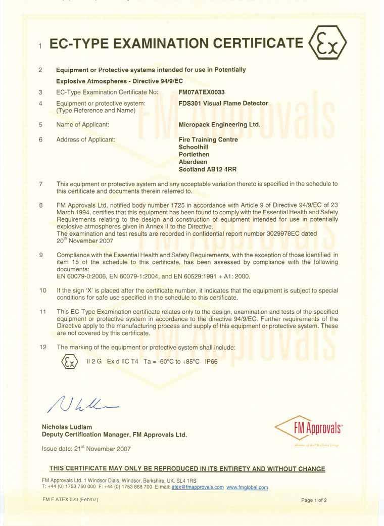
1 Dräger Flame 5000 Colour CCTV Flame Detector Technical Manual en Technical Manual 2-34! WARNING You must read, understand, and follow these instructions for use before you use the flame detector in order to ensure the proper operation and function of the flame detector.
2 Contents For Your Safety... 3 Intended Use... 6 Operation Maintenance...21 Fault Finding Technical Speci cations Approvals Accessories Supplier s Declaration of Conformity Approval Certi cates... 29
3 For Your Safety For Your Safety Strictly follow the Instructions for Use Any use of the device requires full understanding and strict observation of these instructions. The device is only to be used for the purposes speci ed herein. This manual should be carefully read by any individuals who have or will have responsibility for using or maintaining this product. Maintenance The Dräger Flame Detector 5000 must be inspected and serviced at regular intervals and a record kept. Repair and general over-haul of the device may only be carried out by trained service personnel. We recommend that a service contract be obtained with Dräger Safety UK Ltd and that all repairs also be carried out by them. Under no circumstances should the detector housing be opened in a hazardous area. Detectors contain no userserviceable parts and should never be opened, other than for access to the terminal compartment. Under no circumstances should any components be substituted. Failure to comply with this requirement may invalidate the hazardous area certi cation or disturb the critical parameters of the Dräger Flame Detector 5000 resulting in damage to the device or failure to detect res. Observe the chapter Maintenance. Use in areas subject to explosion hazards The Dräger Flame Detector 5000 is certi ed for and intended for use in potentially hazardous areas. Equipment and components which are used in explosion-hazard areas and which have been inspected and approved in accordance with international or European explosion-protection regulations may be used only under the speci ed conditions. The equipment or components may not be modi ed in any manner. Do not drill holes in any housing, as this will invalidate the explosion protection. Check that the materials used in the construction of this detector are compatible with the environment in which they will operate, and that they will not be a ected by any anticipated contaminants. The detector should not be used in an oxygen enriched atmosphere. The purpose of the Dräger Flame Detector 5000 is to detect a ame or re. It may be installed in areas that contain potentially explosive atmospheres, thus it is vital for your safety and that of others that its functions are understood and that every aspect of installation, commissioning and maintenance are carried out correctly. This manual is intended to inform you of all aspects of the Dräger Flame Detector However, if you are in any doubt about any part of these instructions, any function of the equipment, or any operating procedure, please contact Dräger Safety or your local distributor. 3
4 For Your Safety Attention Information on power consumption and operating voltage of the detector can be found in the speci cations section of this manual. This should be read and taken into consideration when specifying cable core sizes to be used. In addition, local regulations should be considered before wiring the system and installation should be completed by appopriately trained personnel. During system tests or maintenance, it is important that any control equipment is inhibited to avoid unwanted actuation or alarms. Dräger Safety UK Ltd. 4
5 For Your Safety Safety Symbols used in this Manual While reading this Manual, you will come across a number of warnings concerning some of the risks and dangers you may face while using the device. These warnings contain signal words that will alert you to the degree of hazard you may encounter. These words, and the hazard they describe, are as follows:! DANGER Indicates an imminently hazardous situation which, if not avoided, will result in death or serious injury.! WARNING Indicates a potentially hazardous situation which, if not avoided, could result in death or serious injury.! CAUTION Indicates a potentially hazardous situation which, if not avoided, could result in physical injury.! NOTICE Indicates a potentially hazardous situation which, if not avoided, could result in damage to the product. 5
6 Intended Use Intended Use Dräger Flame Detector 5000 For use in an area which may contain potentially explosive atmostphere. Used to monitor and trigger the necessary control actions upon the detection of re or ame in a given environment Understanding the System Principle of Operation The Dräger Flame Detector 5000 can operate stand alone or can be integrated with an approved control system. Detectors are typically located throughout the installation in order to achieve speci c detection coverage and ensure that site performance requirements are met. All detectors are capable of providing live colour video images and re alarm/fault signalling to the control equipment. Each detector incorporates within a single unit an imaging device, digital signal processing hardware, and rmware algorithms to process live video images and recognise ame features. The detectors are capable of operating independently: external control equipment is not required for normal functions. However, if an external controller is installed then certain additional features become available, such as remote con guration and rmware management. A remote operator can interrogate the detector and, during an alarm situation, visually verify the hazard. Each detector can be individually con gured to operate seperately as a Flame detector only, or Video Surveillance camera, or as a combined unit. Detector Overview The detector unit is comprised of two primary components, the detector enclosure, and the detector assembly. The detector assembly should not be disassembled or tampered with in any way. The detector is shipped pre-assembled and comes complete with all parts required for installation, including the bracket but excluding the client mounting support, glands and cabling. Optical Test The camera implements an optical check for faulty or contaminated optics. The check measures the contrast in images captured from the video sensor. If the contrast falls below a certain level, the detector will signal an optical fault. Optical testing in the Visual Flame Detector can also be veri ed manually using the Dräger FS Another manual method is simply to view the video from the detector, if the video-out is connected. Detector Sensitivity The Dräger Flame Detector 5000 s response to a re depends on the fuel source and how it is released, re size and distance, orientation to the detector and local ambient conditions. The typical parameters can be made available by contacting Dräger Safety UK Ltd. Explosion-Protection Approval The explosion-protection approvals are valid fo use of the device in gas/vapour-air mixture of combustible gases and vapours under atmospheric conditions. The explosion-protection approvals are not valid for use in oxygen eriched atmostpheres. In the case of unauthorised opening of the enclosure, the explosion-protection approval is void. 6
7 Intended Use! WARNING Do not open the enclosure in the presence of an explosive atmostphere.! WARNING All permits and proper site procedure and practises must be followed and the equipment must be isolated from the power supply before opening the enclosure in the field. Field of View The sensor can detect res of 0.1m 2 or greater, at 44m within a 90 horizontal eld of view. The detector will only respond to visible ames within the eld of view. Hence the detector will not to certain common sources of false alarms such as re ected are radiation. This also reduces the likelihood of cross-propagation of alarms caused by res or combustion products of res burning out with the eld of view. The detectors should be aligned to view the intended hazard taking into account any obstruction and congestion. Software analysis of the actual detector coverage may be required to ensure adequate coverage of the hazards. This analysis can also be used to optimise the number of detectors and the loop con guration. Visual Flame Detector does not have a traditional cone of vision like other IR ame detector s. The detector s eld of view is a rectangular pyramidal shape and represents a radial projection of the detector s rectangular sensing element. The illustrations below show the Field of View and range for a re of 0.1m 2. Horizontal Field of View Vertical Field of View m 40m 30m m 40m 30m m m m 10m -90 5m m
8 Installation of the Dräger Flame Detector 5000 Installation of the Dräger Flame Detector 5000 In considering the application of the Dräger Flame Detector 5000 it is important to know of any conditions that may prevent the detector from responding. The detector provides reliable response to visible ames within its eld of view, and insensitivity to common false alarm sources. Solid obstructions or a direct view of intense light sources may interfere with the detector sensitivity. Sca olding or tarpaulins in the detector s eld of view may reduce coverage. Contamination of the detector window may result in a reduction in sensitivity. The detector provides a live colour video image for surveillance of the protected area. As with conventional video cameras the detector should not face directly towards the sun or a brightly lit scene. In such conditions the detector s automatic exposure control would darken the image in order to avoid overexposure; the resulting picture may be too dark for surveillance purposes. To obtain the best possible picture the detector should be facing away from the sun. In the case of an o shore vessel or platform, the detector should ideally be placed facing inwards towards the plant and with minimal view of the horizon. The detector has a horizontal eld of view of 90 and a vertical eld of view of 65. The location and orientation of the detector in relation to the protected area determines the actual footprint. Achieving the desired coverage depends on congestion within the protected space, the location of the detector(s) and the distance of the detector from the hazard. It may be necessary to install more than one detector within an area in order to achieve adequate coverage. The detector sensitivity, expressed as re size at a distance, is determined visually by the apparent size of the re. This is a function of the fuel source, how it is released and distance from the detector to the re. The detector response time is relatively independent of fuel type and/or distance. In common with other forms of ame detection, the detector s sensitivity is reduced and potentially blinded by dense obscurants such as smoke, fog and other airborne particulates. The detector is insensitive to arc welding, however should not be conducted within 1m of the detector. Mechanical Install. Detector Enclosure The Draeger Flame Detector 5000 s electronics are housed in an enclosure certi ed for use in a hazardous areas. The enclosure comprises of: Front enclosure cover (including the faceplate window) Rear enclosure cover. Enclosure body (with certi cation label). Mounting bracket. The mounting bracket allows the detector s vertical orientation to be adjusted from 0-45, and allows a horizontal rotation of ±45. 8

9 Installation of the Dräger Flame Detector 5000 Detector Enclosure with Bracket Sighting requirements Observe the following: Ensure the mounting position is free from vibration or movement Prevent accidental knocking or forcing out of alignment Where snow or ice build-up is likely, the heater should be enabled To ensure the best possible video image the detector should be facing away from the sun Isolate as far as possible from local electrical interference sources Ensure su cient detection to achieve adequate coverage for all likely hazards Minimise exposure to contamination of the detector face plate Ensure ease of maintenance access to detector (i.e. direct, ladder or sca old access) All these issues are of crucial importance to a successful installation, and they should be given great attention during the detailed design, construction, and commissioning phases of the work.! WARNING Do not drill any holes in the housing as this will invalidate the explosion protection.! WARNING Do not open the enclosure in the presence of an explosive atmosphere. 9
10 Installation of the Dräger Flame Detector 5000 Exposure to Flare Radiation Flame detectors are frequently used where hydrocarbon re hazards are expected; these are quite often processing plants where a are stack is in use nearby. The detector should not have a direct view of the are. Flexibility of mounting location The detector requires a clear unobstructed view of the potential hazard. In order to avoid local obstructions, such as pipe-work and cable trays, a 2m helix should be provided in the detector cable to allow local repositioning of the detector. Mounting Arrangements Firm, vibration free mountings are essential for the operation of optical systems and the detector should, wherever possible, be xed to rigid mountings. Thermal Disruption Thermal convection plumes and exhaust gas plumes generally exhibit a visual mirage e ect. In most cases this does not a ect detector operation or sensitivity. The detector does not respond to black body radiation near the exhaust. Optical Contamination There are many sources of contamination such as oil, water (deluge water, rain and sea-spray), snow, ice, and internal misting. The design of the detector incorporates an internal heater in order to resist condensation and ice build-up. Excessive contamination of the detector faceplate may result in an increased maintenance requirement and potentially reduce the detector s sensitivity. Where detectors are mounted at low level, care should be taken to avoid contamination (such as water and oil) from equipment above the detector. Care should be taken in sighting the detector to minimise the likelihood of such contamination. Fog, smoke and other similar airborne contaminants a ect the detector s sensitivity by reducing the detector s range. Enclosed Areas In enclosed areas, if dense smoke is expected to accumulate at the onset of the re, the detectors should be mounted 1-2m below the ceiling level. The mounting bracket The detector mounting bracket is designed to allow the detector to be mounted from a horizontal plane. The bracket supplied with the detector and the dimensions of the xing holes are illustrated on the following page. 10
11 Installation of the Dräger Flame Detector 5000 Detector mounting bracket Detector mounting bracket dimensions Dimensions shown in Millimeters 11
12 Installation of the Dräger Flame Detector 5000 Electrical Install Detector Electronics Subassembly The eld wiring is accessed by removing the rear enclosure cover and all terminations are accessible without the need to access the electronics module mounted in the front portion of the enclosure.! WARNING For European (ATEX) installations, IEC/EN Electrical Installations in Hazardous Areas and ICE/EN Inspection and Maintenance in Hazardous Areas should be strictly observed.! WARNING For installations all Local and International regulations should be strictly observed. Earthing & Screening Requirements It is important to ensure that the system is correctly connected to earth. Incorrect or poor earthing can adversely a ect system operation and may result in intermittent RS485 communications and poor video image quality.! WARNING The equipment must be properly earthed to protect against electrical shock and to minimise electrical interference. The system 0V should be connected to a clean earth at only one point; generally this should be at the panel power supply (or 0V bus bar). Where PC equipment is connected to the RS485 and Video signals, care should be taken to ensure that the PC s and Panel s power supply are at the same ground potential. Even small di erences in earth potentials can cause an earth fault current to ow resulting in video corruption. Where this is not possible either the PC s local supply should be isolated and the PC s connected to the system clean earth, or alternatively, the Video and RS485 signals should be isolated. The Dräger Safety UK Ltd twisted pair to BNC video converter (VTP4) and RS232 to RS485 converter (RS2485IF) can be used so long as the maximum potential di erence between each earth does not exceed ±5V, as identi ed below. In distributed systems with multiple DC-DC power supply units all 0V supplies must be connected together to a common clean earth. Where this is not possible each system can either be connected to a local clean earth so long as the maximum potential di erence between each earth does not exceed +4 to -1Vdc, alternatively the Video and RS485 signals can be galvanically isolated from the central system. Where earth fault monitoring is used care should be taken to ensure that the system 0V to earth potential is not exceeded. The detector enclosure is to be connected to a local earth and the detector cable screens (shields) should be cut back to the crotch and not terminated within the detector. If the detector enclosure cannot be connected to a local earth 12
13 Installation of the Dräger Flame Detector 5000 then care should be taken to ensure the cable armour braid provides a suitable earth or that the enclosure earth stud (external) is separately connected to a suitable earth point using a single core 4mm 2 earth cable. All detector cable screens should be connected to the local clean earth at the control panel. The screens (and twisted pairs) should be maintained to within 1 (25.4mm) of the terminations at the detector, within all junction boxes and at the control panel. Where unscreened cables are used for panel wiring, then all cables must be suitably twisted into pairs and video cables should be segregated from other signal sources. Power Supply The detector requires an absolute minimum supply voltage of 18V, as measured at the detector terminals. The system power supply voltage and power distribution should be arranged such that on the longest cable run the detector(s) has a supply voltage of greater than 18V. All detectors must share a common 0V supply. In distributed systems with multiple DC-DC power supply units all 0V supplies must be connected together. Where this is not possible the RS485 and Video signals may need to be galvanically isolated, such as with a bre optic transceiver. To prevent RS485 communications or video corruption the maximum voltage drop on the 0V return must not exceed +4V or -1V. Voltages greater than these will exceed the common mode input range of the RS485 and Video drivers. Power supply cable selection is described in section: Detector Power Supply Cabling Detector Wiring Terminals The wiring terminals and con guration links are mounted in the rear section of the enclosure and are accessible by removal of the rear cover from the enclosure. The electronics and the eld terminals are separated so that there is no reason to remove the electronics in order to access the eld terminals. This is to prevent damage to the electronics when the unit is being connected to the eld cable. The device is supplied in one of two options: 1. As a unit that provides relay contacts for the alarm and fault circuits across which alarm and end of line resistors are tted. When the unit is disconnected from the re panel, the output from terminals A and B switch to the RS485 protocol; this allows a Dräger Engineer access to the detectors con guration from the local equipment room. 2. As a unit that provides 4-20mA output. When the unit is disconnected from the re panel, the output from terminals A and B switch to the RS485 protocol; again this allows a Dräger Engineer access to the detectors con guration from the local equipment room. This may then be used to access the software revision within the detector via the get settings menu as described in the RS485 Communications section. The alarm relay and the 4-20mA output is factory selectable for latching and non-latching operation. If the latching mode is selected then if an alarm is generated the detector will remain in alarm until the power supply to the unit is interrupted. If the non-latching operation is selected then the detector will remain in alarm for a minimum of 15 seconds, the re panel to which the detector is connected must be capable of latching the alarm and there is no need to interrupt the power supply to the detector to reset the alarm. Local authority having jurisdiction approval is required for connection to FM Approved re alarm control units. 13
14 Installation of the Dräger Flame Detector 5000 Detector Wiring Terminals (Rear Detector with cover removed) Relay Mode Connections The following table provides a function summary of each terminal if the detector is ordered in relay mode. Terminal Terminal No. Description +24v 1 +24V Supply A 0v 2 0V Supply A A 3 Sense from re panel 1 7 B 4 Return signal to re panel 8 14 VID+ 5 Video +Ve VID- 6 Video Ve 485A 7 RS485 termination +Ve +24v 8 +24V Supply B 0v 9 0V Supply B VIDEO -VE VIDEO +VE To Fire Panel From Fire Panel 0 VDC +24 VDC C 10 EOL resistor D 11 EOL resistor ALRM 12 Alarm Resistor ALRM 13 Alarm Resistor 485B 14 RS485 termination -Ve If the detector is connected in the above manner and if a re alarm is signalled, with the alarm resistor connected between terminals 12 & 13, then the alarm resistor will appear across terminals 3 & 4. The EOL resistor connected between terminals 10 & 11 normally appears across terminals 3 & 4 and in the event of a fault the resistor appears open circuit. If terminals 3 & 4 are disconnected from the re panel, these wires then provide a RS485 connection to the detector. This connection may then be used to up load or down load information to the detector. 14
15 Installation of the Dräger Flame Detector mA Connections The following table provides a function summary of each terminal if the detector is ordered in 4-20mA mode. Terminal Terminal No. Description +24v 1 +24V Supply A 0v 2 0V Supply A A 3 Tie to +24 Volts at panel B ma source VID+ 5 Video +Ve VID- 6 Video Ve 485A 7 RS485 termination +Ve +24v 8 +24V Supply B optional VIDEO -VE VIDEO +VE 4-20mA Source 0 VDC +24 VDC 0v 9 0V Supply B optional C 10 Not used D 11 Do not connect ALRM 12 Do not connect ALRM 13 Not used 485B 14 RS485 termination -Ve If the detector is connected in the above manner if a re alarm is signalled then the 4-20mA outputs generate 18mA if a fault develops the 4-20mA signal indicates 0 or 2 ma dependant on the fault see table for default current levels. If terminals 3 & 4 are disconnected from their connections these wires then provide a RS485 connection to the detector. This connection may then be used to up load or down load information to the detector. Default 4-20mA settings Event Catastrophic Failure Optical Fault Healthy condition Alarm Over range Output 0mA 2mA 4mA 18mA 21mA There is a tolerance on the ma outputs of ±5%, other values maybe selected at the point of order. 15

16 Installation of the Dräger Flame Detector 5000 RS485 Communications The optional RS485 twisted pair cable is connected to the detector RS485A +ve signal terminal and the RS485B -ve signal terminal. The RS485 connection can be used to read the software revision within the detector. In order to access this information connect the RS485 input of a RS485 to RS232 to terminals 7 & 14. Connect the RS232 input of a RS485 to RS232 to a PC install DFG software on the PC. The DFG Software can be used to interogate the Flame 5000 Detector, for any further assistance contact Dräger Safety UK Ltd. The software revision will be shown in the get settings box as indicated adjacent. Video (twisted pair) The video twisted pair cable is connected to the detector +Video signal on terminal 5 and the -Video signal on terminal 6. Point to Point Connections In a point to point connection a single detector is connected to the power, RS485 (or ma or Relays) and Video cables. This arrangement has the best reliability and availability since any single failure in the eld equipment or cabling a ects only the one detector. Cable Selection The installation, local regulations, and standards determine the overall cable speci cation. This section speci es suitable cable characteristics to ensure correct operation of the ame detector. There are several di erent cabling methods available, each with advantages and disadvantages: Three twisted pair cable, one each for DC power, RS485 and video signals Two twisted pair cable for DC power and ma or Alarm relays, interchangeable with RS485 Three twisted pair cable for DC power and ma, or Alarm relays, interchangeable with RS485 and one pair for video. Three wire, DC power and ma (Current source output). NOTE: Table below shows absolute maximums for cable lengths; try not to approach these values. Typical cable lengths (24V Supply) Installation based on 24V nominal supply Number of Flame Detectors Maximum Power (W) Maximum Cable Length (m) with 1.5mm 2 Conductors (12 ohms/km) Maximum Cable Length (m) with 2.5mm 2 Conductors (7.6 ohms/km) Detector and Heater Detector (no Heater) 1 6 1,000 1,578 NOTE: Increasing the supply voltage to 26V would increase the maximum cable lengths by +30%. The overall performance and the transmission distance depends on the selected twisted pair cable. Individually screened twisted pairs o er better electrical immunity. 16
17 Installation of the Dräger Flame Detector 5000 It is not necessary for the DC power cable to be a twisted pair or individually screened, a 2-core stranded cable with an overall screen is su cient. The minimum conductor size is determined by the cable length, the number of Flame Detectors on each loop, and the maximum allowed voltage drop at the last detector. To prevent RS485 and Video common mode problems this is limited to a maximum of four volts (4V) on the negative supply (0V). Equation 1 : DC Supply Conductor Resistance Calculation Vs Vpd( 4V) R km V pd min Vd 2 min Pd N Vs min L km Vpd = Potential across each conductor (limited to 4V) Vsmin = Minimum Supply Voltage Vdmin = Minimum Detector Voltage (18V) Pd = 18 watts per Flame Detector (inc. Heater) or 6 watts excluding Heater N =Number of Detectors Lkm = Cable Length in Kilometres Rkm = Maximum Conductor Resistance per Kilometre Use the value of R km calculated above to select a suitable gauge of conductor, alternatively, to calculate the maximum cable length from a known conductor resistance swap R km and L km in the above equation. The supply voltage and cable cross-sectional area (which equates to its resistance) limits the maximum cable length, increasing the supply voltage (up-to a maximum of 32V) can dramatically increase cable length. Prudence dictates that a cable is selected with a lower resistance than calculated above, with su cient allowance for the e ects of crimps, terminals and ageing which can increase overall resistance. Where a single cable cross sectional area cannot be found to satisfy both the needs of the power and signal conductors consideration should be given to using multiple paralleled conductors of a smaller cross section for the power. Video (Twisted Pair) The video cabling should be a twisted pair stranded cable with an overall screen. Where multi-core cables are used then individual screened twisted pairs are recommended. The cable should have the following characteristics: Video (Twisted Pair) Cable Characteristics Cable Characteristic Capacitance Conductor Inductance Characteristic Impedance Resistance 1MHz Nominal nf/Km Absolute Limit 90 to nf/Km 150R 6db 0.7mH/Km The maximum cable length is dependent on the cable manufacturer s attenuation speci cation, which is approximately proportional to conductor size. The characteristic impedance of a transmission line is a function of the physical dimensions of the conductor and the permittivity of the dielectric (the insulation), at high frequencies this is approximately equivalent to: 17
18 Installation of the Dräger Flame Detector 5000 Equation 2: Characteristic Impedence Calculation Zo( ) L C L C Zo = Cable Impedance (mh) = Cable Capacitance ( F) = Characteristic Impedance (Ohms) The RS485 communications cabling should be a twisted pair stranded cable with an overall screen. Where multicore cables are used then individual screened twisted pairs are recommended. The cable should have the following characteristics: RS485 Communications Cable Characteristics Cable Characteristic Capacitance Conductor 1MHz Inductance Characteristic Impedance Resistance Nominal nf/Km Absolute Limit 90 to nf/Km dB 0.7mH/Km The maximum cable length is dependent on the cable manufacturer s attenuation speci cation, which is approximately proportional to conductor size. The characteristic impedance of a transmission line is the same as for the video above. Installation Check-Points Experience has shown that poor installation and commissioning practice may result in an unreliable re detection system that is prone to malfunction, unwanted alarms, and at the same time fails to meet the site performance targets. Before installing the detector it is important to take into account where it is to be located and how it is to be mounted. Mechanical Installation When locating the Dräger Flame Detector 5000 consideration should be given to maintenance access to the detector. The detector mounting should be secure and vibration free. It is advisable to check the detection locations, prior to fabrication of the mounting supports, as changes are frequently made during construction at site which can a ect detector coverage. The installation should allow for easy detector removal for maintenance or repair The detector should be xed to a stable supporting structure using the mounting bracket provided. The supporting structure must allow for horizontal adjustment of the detector orientation. The support structure should be in place prior to detector installation. The threaded ame path of the enclosure cover and body must be protected from damage during installation. Any such damage can destroy the validity of the enclosure. The detector electronics shall be protected from mechanical damage and external sources of EMI such as X-rays, RFI and electrostatic discharge. Fit the mounting bracket to the support structure using 8mm bolts (not provided). The detector (bracket) should be oriented to provide the desired coverage. The hex head bolts should be tted to the enclosure body prior to mounting to the bracket. The detector enclosure 18
19 Installation of the Dräger Flame Detector 5000 body should then be tted to the mounting bracket. The bolts t into key slots in the bracket. Twist the enclosure to locate the bolts; these are then tightened using a 6mm Allen key. Electrical Installation In order to maintain compliance with the EMC regulations it is essential the electrical installation be engineered correctly. It is advisable to check the detection locations, prior to fabrication of the mounting supports, as changes are frequently made during construction at site. Detector cabling must be segregated from cables carrying high-speed data or high energy and/or high frequency signals and other forms electrical interference. The detector requires a clear unobstructed view of the local hazard. In order to avoid local obstructions, such as pipe-work and cable trays, a 2m helix should be allowed in the detector cabling. The detector should only be installed just prior to commissioning. Experience shows that the detector can be damaged due to cable testing operations (Insulation Tests, etc) Isolate all associated power supplies. Ensure that they remain OFF until required for commissioning. The threaded ame path of the enclosure cover and body must be protected from damage during installation. Any such damage can destroy the validity of the enclosure. The electronics subassembly shall be protected from mechanical damage and external sources of EMI such as X-rays, RFI and electrostatic discharge. The enclosure s external earth stud should be connected to a local earth point. Remove the blanking plug(s) from the enclosure body gland entries. Fit approved cable glands using sealing washers to maintain ingress protection. Prepare the cable tails. The cable screens should be cut back to the crotch at the detector and insulated from contact with the enclosure or any other local earth. The twist in each pairs should be maintained to within 1 (25mm) of the termination. Cable tails should be 8 (200mm) long. Where plastic junction boxes are used the cable screens (shields) should be maintained to within 1 (25mm) of the termination and fully insulated. Where unscreened cables are used for panel wiring, then all cables must be suitably twisted into pairs and video cables should be segregated from other signal sources. All cable screens (shields) should be connected to the local clean earth at the control panel. The screens and twisted pairs should be maintained to within 1 (25mm) of the terminations. 19
20 Operation Operation Detector Start-up procedure When the power is initially turned on there is a delay of approximately thirty seconds. The system performs an internal test and system initialisation. Detector Signals The Flame detector generates a 0-20mA signal to indicate its status, or provides relay outputs. This should be checked during the installation of the detector. Alternatively the status and operation of the device can be monitored by the colour of the LED illuminated.! WARNING Operators must be properly trained and aware of what actions to take in the event of a fire being detected. Status Indicators The detector LED indicator is used to reveal the Dräger Flame Detector 5000 s current state, as shown below: LED Status Diagnostic Chart Current (Source) isolated signal output LED Colour Status Indicator Steady OFF No Power Green Healthy Steady Yellow Fault Flashing Yellow/Green 24V/0V terminals polarity reversed. Red Alarm Event Catastrophic Failure Optical Fault Healthy condition Alarm Over range Output 0mA 2mA 4mA 18mA 21mA The LED Status indicator is located on the face of the detector underneath the camera lens, as illustrated in the graphic below. Visual Flame Detector Draeger Flame 5000 Visual Flame Detector Draeger Flame
21 Maintenance Maintenance Detector Maintenance! WARNING Repair of all equipment should be only performed in a safe area and by trained personnel. Once installed there are no user serviceable parts within the detector. The only servicing requirements are to ensure that the detector is fully functional and to ensure that the lenses are clean. The terminal compartment cover and front cover threads must be lightly lubricated with non-setting grease prior to re-assembly. This maintenance schedule is intended for guidance only. The actual level of maintenance required will depend on the severity of the operating environment and the likelihood of damage or the rate of contamination from oil, sea spray, deluge system etc. It is advisable to regularly review maintenance reports and adapt the maintenance period to the operating environment. A function test of the detectors using the Dräger FS-5000 (See Accessories, page 26) should be carried out regularly. Maintenance Intervals Periodic maintenance checks may be performed in accordance with appropriate codes of practice or local regulations e.g. in Europe EN applies. These rst ve points relate to the general inspection and maintenance of the detector and faceplate, this should be carried out at least every 6 months. Detectors that require maintenance should be taken o line and inhibited. Detectors which require to be opened up will need to be isolated electrically. Ensure that panel wiring and terminations associated with all units under test are in good order. Ensure that detector mounting arrangements are secure and undamaged. Ensure that the detector enclosure is intact and undamaged. Ensure that all associated cables and glands are correctly made up, secure and undamaged. Clean the enclosure faceplate (outside) with a mild detergent solution and a soft cloth until the window is clear of all contamination. Wash the window thoroughly with clean water and dry with a clean lint free cloth or tissue. Assess requirement for opening the enclosure, for maintenance or cleaning. The nine points below are for more speci c inspection and maintenace of the detector enclosure, which should be performed at least once a year. These points focus as a close external visual inspection and internal inspection if required. Open the detector enclosure, if required, by removing the enclosure cover. This exposes the enclosure ame path and detector electronics. Avoid damage to the ame path and faceplate. Clean the enclosure cover and body ame paths with a dry clean cloth to remove any contamination. If the ame path or threads are badly pitted the component should be replaced. 21
22 Fault Finding Check the O ring seal on the enclosure cover to ensure that it is not damaged or perished; replace as required. NOTE: That the ingress protection is compromised if the seal is not correct. Clean the enclosure faceplate (inside) with a mild detergent solution and a soft cloth until the window is clear of all contamination. Wash the window thoroughly with clean water and dry with a clean lint free cloth or tissue. No-setting waterproof grease should be evenly applied to the ame path on both the enclosure cover and body. Clean the detector lens. This should be done with a soft, dry and clean cloth. Avoid touching the electronics. Clean the detector enclosure faceplate. Use a degreasing agent on the outside in order to remove deposits. Visually inspect detector electronics and inside the enclosure body for any sign of damage or moisture, replace or rectify as required. The enclosure cover must be screwed on to a minimum of 5 full turns or until fully tight and secured using the locking screw provided. The remaining points cover detector function testing, this should be done on a continuous basis or every 6 months depending on the environment. Reinstate the detector back into service. Ensure that inhibits are applied, then, using the Dräger FS-5000, function test the detector. Note the detector LED indicator, within the detector housing, changes colour to RED. Check the complete display system for correct function and indication. Functional Testing The detector can be function tested using the Dräger FS-5000, which has been speci cally designed to provide a convenient means of eld testing the detector.! CAUTION Use only Draeger approved parts and accessories with this equipment.! CAUTION Do not attempt to replace the window as the glass and the front cover are individually matched pairs to me the stringent requirements of the hazardous area certification.! CAUTION To maintain safety standards, commissioning and regular maintenance should be performed by qualified personel. 22
23 Fault Finding Fault Finding Removal of the Electronics There are no user replaceable parts within the electronic module, any attempt to repair or dismantle the electronic subassemblies will void the warranty. If any fault is suspected within the electronics module the module is to be returned to Dräger Safety UK Ltd for investigation and repair if required. Diagnostics It is impossible to provide fault diagnostics for every possible detector fault. In all cases it is advised that the following best practises are followed: Only make one change at a time (changing more than one part at a time makes diagnosis very di cult) Check the most obvious possible causes rst Work systematically through the problem Keep good notes on the original problem, each step taken and the results observed Power Supply If the detector LED indicator is OFF then there may be a power supply fault. When investigating power supply faults it is important to check that all voltages are within the detectors operating range (18V - 32V) under full load conditions as the voltages measured under no load conditions can be misleading. Live Video Images The live video signal is susceptible to more potential problems than the alarm signals. The signal is an analogue transmission and available for operator scrutiny. The cabling is critical to video image quality. Due to the nature of the video signal, video corruption can appear di erently on each detector/installation. 23
24 Technical Specifi cations Technical Speci cations Mechanical Enclosure Enclosure Material: Aluminium Alloy Grade LM25, Stainless Steel 316 Enclosure Finish: Epoxy Coated Finish, Dräger Blue Weight: 2.5 kg, 5.5 lbs (2.8 kg, 6.2 lbs Stainless Steel ver) Dimensions (L x D): 220 x 100 mm, (9 x 4 inches) Cable Entries: M20, M25 or 3/4 NPT Terminal Wire Size: 2.5mm 2 Ingress Protection: IP 66, NEMA 4X Temperature & Humidity Operating T amb : Storage T amb : Humidity: -60 C to +85 C T4-60 C to +85 C 5-95% Relative Humidity Non-condensing Mounting Support Fixings: M8 x2 Vertical Adjustment: 0-45 Axial (Horizontal) Adjustment: ±45 24
25 Approvals Electrical Operating Voltage: Supply Ripple: Power Consumption: Heater Power Consumption: Detector Shutdown Voltage: (low supply) Power-On Delay: 18-32VDC (24VDC Nominal) inc ripple, (Max 30VDC in Canada) 1V pk-pk 6W (max. 15W with Heater) 12W <17VDC No more than 30 seconds, during in which System Testing and System Initialisation occurs. RS 485 Transceiver Line Termination Resistor: 120 Driver Di erential: 1.5 VDC Driver Fan Out: 0-3 UL Receiver Common Mode -7 to +12 VDC Input Range: Receiver Input Threshold: -0.2 VDC (LO) to +0.2 VDC (HI) Receiver Input Resistance: >12 k Receiver Unit Load: 1 Video Driver (Twisted Pair) Line Termination Resistor: Driver Output Resistance: Driver Di erential Output Voltage: Driver Di erential Output Voltage (loaded): Driver Shutdown Resistance (TRI-STATE): Driver Fan Out: VDC 2 VDC 4.8 k 0-1 UL 25
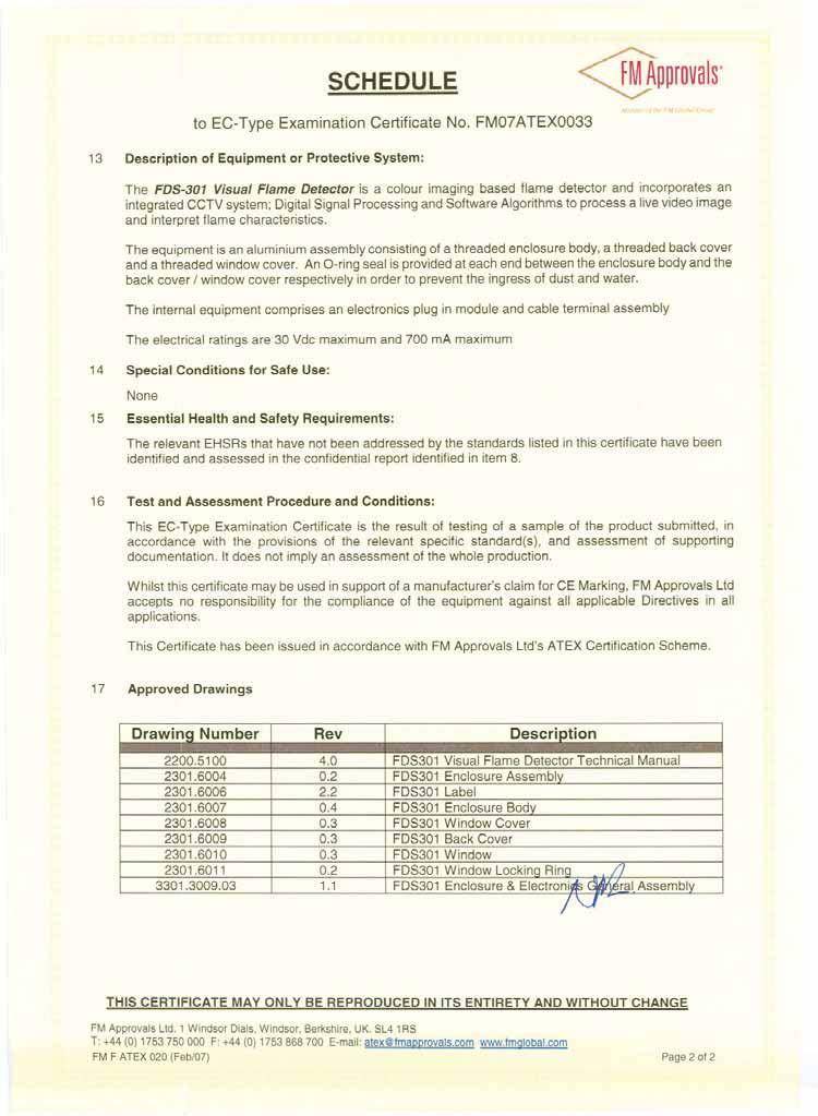
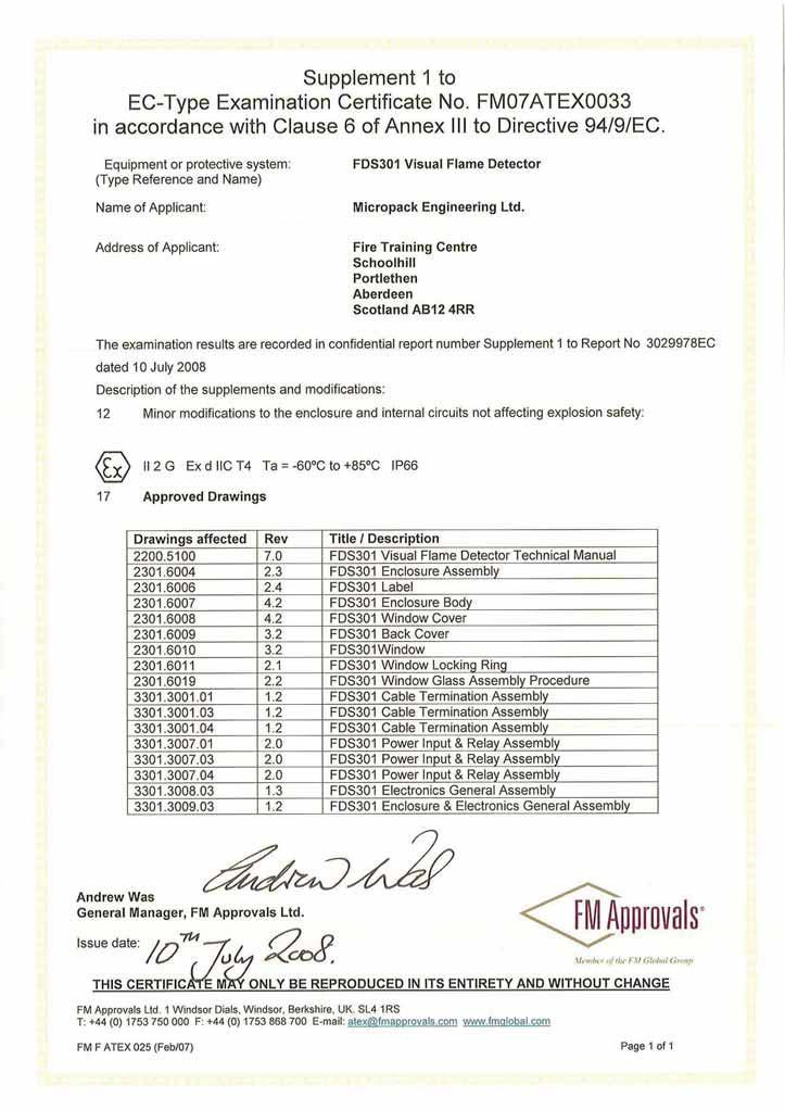
26 Approvals Approvals ATEX Certi cate Number: FM07ATEX 0033 II 2 G Exd IIC IECEx Certi cate Number: FME FM Class I Div 1 Groups B, C, D, T4 Ambient: -60 C to +85 C Class I Zone 1 AEx/Ex d IIC T4 Ambient: -60 C to +85 C CE GEC: EN55022 & 082 Electromagnetic Compatibility: Response Time: Operating Distance: Emissions: Immunity: Conducted Emissions: Radiated Emissions: ESD: RF Field (Amplitude): Transient: Surge: RF Field (Common Mode): EN :2001 EN :1995 +A1:1998 +A2:2003 EN55022:1998 Class/Level B EN55022:1988 Class/Level B EN :1995 ±6kV (Contact) ±8kV (Air) EN :2002 +A1: V/m 100% & 80% modulation EN :1995 +A1:2001 +A2:2002 ±1kV EN :1995 +A1:2001 Line - Line, Line - Earth ±1kV EN :1996 +A1: V rms 100% & 80% modulation min. 4 seconds (upto 30 seconds max.) 2-44 m Hazardous Area Label This label shows the certi cation and conditions of the Dräger Flame Detector Draeger Safety U.K. Limited, Blyth, Northumberland, NE24 4RJ, U.K. Manufactured by: Micropack Engineering Aberdeen, Scotland, AB12 4RR TYPE: FLAME 5000 SERIAL No: YEAR: ENTRY: M25 M20 ½" NPT ¾" NPT Single Dual WARNING: DO NOT OPEN WHEN EXPLOSIVE ATMOSPHERE MAY BE PRESENT 3260 AMBIENT: -60ºC +85ºC 1725 II 2 G Ex d IIC T4 TYPE 4, IP66 Class I DIV 1 GROUPS B,C,D,T4 AMBIENT: -60ºC +85ºC AMBIENT: -60ºC +85ºC FM07ATEX 0033 Class I Zone 1 AEx/Ex d IIC T4 IECEx FME AMBIENT: -60ºC +85ºC Maximum Voltage: 30VDC SEAL CONDUIT WITHIN 18" OF ENCLOSURE ENTRANCE Maximum Current: 700mA WARNING: REFER TO FLAME 5000 TECHNICAL MANUAL BEFORE INSTALLING OR MAINTAINING THIS UNIT 26
27 Accessories Accessories Description Part Number Dräger FS Dräger CCTV Balanced Line to BNC Video Converter Dräger Flame 5000, M20, 4-20mA, PAL video mode, Aluminium Dräger Flame 5000, M20, Relay, NTSC video mode, Aluminium Dräger Flame 5000, 3/4 NPT, Relay, NTSC video mode, Aluminium Dräger Flame 5000, 3/4 NPT, 4-20mA, PAL video mode, Aluminium Dräger Flame 5000, M25, 4-20mA, PAL video mode, Aluminium Dräger Flame 5000, M25, Relay, NTSC video mode, Aluminium Dräger Flame 5000, M20, 4-20mA, PAL video mode, Stainless Steel Dräger Flame 5000, M20, Relay, NTSC video mode, Stainless Steel Dräger Flame 5000, 3/4 NPT, Relay, NTSC video mode, Stainless Steel Dräger Flame 5000, 3/4 NPT, 4-20mA, PAL video mode, Stainless Steel Dräger Flame 5000, M25, 4-20mA, PAL video mode, Stainless Steel Dräger Flame 5000, M25, Relay, NTSC video mode, Stainless Steel Dräger Flame 5000, M20, 4-20mA, NTSC video mode, Aluminium Dräger Flame 5000, M20, Relay, PAL video mode, Aluminium Dräger Flame 5000, ¾ NPT, 4-20mA, NTSC video mode, Aluminium Dräger Flame 5000, ¾ NPT, Relay, PAL video mode, Aluminium Dräger Flame 5000, M25, 4-20mA, NTSC video mode, Aluminium Dräger Flame 5000, M25, Relay, PAL video mode, Aluminium Dräger Flame 5000, M20, 4-20mA, NTSC video mode, Stainless Steel Dräger Flame 5000, M20, Relay, PAL video mode, Stainless Steel Dräger Flame 5000, ¾ NPT, 4-20mA, NTSC video mode, Stainless Steel Dräger Flame 5000, ¾ NPT, Relay, PAL video mode, Stainless Steel Dräger Flame 5000, M25, 4-20mA, NTSC video mode, Stainless Steel Dräger Flame 5000, M25, Relay, PAL video mode, Stainless Steel
28 Supplier s Declaration of Conformity
29 Approval Certi cates
30
31
32
33
34
35 Thank you for reading this data sheet. For pricing or for further information, please contact us at our UK Office, using the details below. UK Office Keison Products, P.O. Box 2124, Chelmsford, Essex, CM1 3UP, England. Tel: +44 (0) Fax: +44 (0) Please note - Product designs and specifications are subject to change without notice. The user is responsible for determining the suitability of this product.
Dräger Flame 3000 Visual Flame Detector Instructions for Use
 D en Instructions for Use Dräger Flame 3000 Visual Flame Detector Instructions for Use WARNING Strictly follow the Instructions for Use. The user must fully understand and strictly observe the instructions.
Dräger Flame 5000 Flame Detection
 Dräger Flame 5000 Flame Detection The Dräger Flame 5000 is an imaging based explosion proof flame detector This visual flame detection system uses digital image processing and advanced algorithms to process
Dräger Flame 5000 Flame Detection
 Dräger Flame 5000 Flame Detection The Dräger Flame 5000 is an imaging based explosion proof flame detector This visual flame detection system uses digital image processing and advanced algorithms to process
APPLICATION OF VISUAL FLAME DETECTION
 APPLICATION OF VISUAL FLAME DETECTION AIRCRAFT HANGARS Graham Duncan Micropack Business Development Manager When a fire occurs in an aircraft hangar the effects are devastating. The cost to replace a hangar
INSTRUCTION MANUAL (ATEX/IECEx/SIL2) BExBG05D-SIL Flameproof Xenon SIL 2 Beacons For use in Flammable Gas and Dust Atmospheres
 BExBG05D-SIL Flameproof Xenon SIL 2 Beacons For use in Flammable Gas and Dust Atmospheres") INSTRUCTION MANUAL (ATEX/IECEx/SIL2) BExBG05D-SIL Flameproof Xenon SIL 2 Beacons For use in Flammable Gas and Dust Atmospheres 1) Introduction The BExBG05D-SIL is a flameproof beacon which is certified
INSTRUCTION MANUAL (ATEX/IECEx/SIL2) BExBG05D-SIL Flameproof Xenon SIL 2 Beacons For use in Flammable Gas and Dust Atmospheres 1) Introduction The BExBG05D-SIL is a flameproof beacon which is certified
standards: standards:
 INSTRUCTION MANUAL D2xB1LD2 LED Beacons For use in Hazardous Locations 1) Warnings DO NOT OPEN WHEN AN EXPLOSIVE ATMOSPHERE IS PRESENT DO NOT OPEN WHEN ENERGISED POTENTIAL ELECTROSTATIC CHARGING HAZARD
Dräger Flame 2500 Flame Detection
 Dräger Flame 2500 Flame Detection Working in areas with combustible gases, vapours or materials requires fire/ flame detection as a life-saving necessity. The best solutions must combine state-of-the-art
IFD-E Flame Detector User Manual
 IFD-E Flame Detector User Manual 2 Hochiki Europe (UK) Ltd General Description The flame detector is designed for use where open flaming fires may be expected. It responds to the light emitted from flames
Dräger Polytron Pulsar 2 Detection of flammable gases and vapours
 Dräger Polytron Pulsar 2 Detection of flammable gases and vapours The Dräger Polytron Pulsar 2 is the latest infrared technology in open path gas detection. Equipped with all the same functions as the standard
IFD-E Flame Detector User Manual
 IFD-E Flame Detector User Manual 2 Hochiki Europe (UK) Ltd General Description The flame detector is designed for use where open flaming fires may be expected. It responds to the light emitted from flames
Instructions xwatch Explosion-Proof Camera X /
 Instructions xwatch Explosion-Proof Camera X7050 2.1 6/09 Table Of Contents Description............................................ 1 features............................................... 1 General Application
ADDENDUM. xwatch Explosion-Proof Camera with X-Series Flame Detectors DESCRIPTION GENERAL APPLICATION INFORMATION
 ADDENDUM xwatch Explosion-Proof Camera with X-Series Flame Detectors DESCRIPTION The xwatch Explosion-Proof Camera is available as a factory installed option with any of the Det Tronics X Series line of
Guidance on Video Smoke Detection Technology (VSD)
") Guidance Note Guidance on Video Smoke Detection Technology (VSD) Guidance on Video Smoke Detection Technology (VSD) SCOPE... 3 INTRODUCTION... 4 WHAT IS VSD?... 5 STANDARDS... 7 GENERAL GUIDANCE ON THE
Guidance Note Guidance on Video Smoke Detection Technology (VSD) Guidance on Video Smoke Detection Technology (VSD) SCOPE... 3 INTRODUCTION... 4 WHAT IS VSD?... 5 STANDARDS... 7 GENERAL GUIDANCE ON THE
Dräger Flame 2100 Flame Detection
 Dräger Flame 2100 Flame Detection Working in areas with combustible gases, vapors, or materials requires fire/ flame detection as a life-saving necessity. The best solutions must combine state-of-the-art
INFRARED PRODUCTS FOR MONITORING SMOKELESS FLARES, PILOTS, AND FLAME INTENSITY
 INFRARED PRODUCTS FOR MONITORING SMOKELESS FLARES, PILOTS, AND FLAME INTENSITY >OLYL >H]LSLUN[O 4H[[LYZ SMOKELESS FLARE MONITOR Smokeless Flare Monitor (FM) Smokeless flares incinerate flammable hazardous
ICS Regent. Fire Detector Input Modules PD-6032 (T3419)
") ICS Regent Fire Detector Input Modules (T3419) Issue 1, March, 06 Fire detector input modules provide interfaces for 16 fire detector inputs such as smoke detectors, flame detectors, temperature detectors,
ICS Regent Fire Detector Input Modules (T3419) Issue 1, March, 06 Fire detector input modules provide interfaces for 16 fire detector inputs such as smoke detectors, flame detectors, temperature detectors,
FIRERAY 5000 range USER GUIDE
 FIRERAY 5000 range USER GUIDE 0044-003-04 IMPORTANT PLEASE NOTE: The beam path MUST be kept clear of obstructions at all times! Failure to comply may result in the Detector initiating a Fire or Fault signal.
DET-TRONICS SPECIFICATION DATA. Eagle Quantum EQ2200UVHT For Use With C7050B Continuous Duty High Temperature UV Flame Detector DESCRIPTION
 DET-TRONICS SPECIFICATION DATA Eagle Quantum EQ2200UVHT For Use With C7050B Continuous Duty High Temperature UV Flame Detector DESCRIPTION The EQ2200UVHT UV Flame Detector is used with the Eagle Quantum
FIRERAY 2000 EExd Hazardous Area Smoke Detector Installation Guide
 FIRERAY 2000 EExd Hazardous Area Smoke Detector Installation Guide KEY FEATURES Flameproof Receiver and Transmitter Standard Fireray Controller Unit High Coverage - up to 1500 2 m per system Low Cost Beam
Dräger Polytron 5200 CAT Detection of flammable gases and vapours
 Dräger Polytron 5200 CAT Detection of flammable gases and vapours The Dräger Polytron 5200 CAT is a cost-effective explosion-proof transmitter for the detection of flammable gases in the lower explosion
Dräger Flame 2500 (IR3) Flame Detection
 Flame Detection") Dräger Flame 2500 (IR3) Flame Detection With its triple IR sensor The Dräger Flame 2500 detects hydrocarbonbased fires even over greater distances. Moreover, it offers a high reliability against false
Dräger Flame 2500 (IR3) Flame Detection With its triple IR sensor The Dräger Flame 2500 detects hydrocarbonbased fires even over greater distances. Moreover, it offers a high reliability against false
Multi-Spectral, Digital, Infrared Electro-Optical. FSC Model No. s. Unitized, Two Stage, Quick Response Flame Detectors.
 Fire Sentry Corporation (FSC) 593 Apollo Street Tel.: 714-671-1100 Brea, California 92821 Fax: 714-671-5821 Multi-Spectral, Digital, Infrared Electro-Optical FSC Model No. s FS10-R and FS10-A Unitized,
INSTRUCTION MANUAL (ATEX/IECEx/SIL2)
") INSTRUCTION MANUAL (ATEX/IECEx/SIL2) BExS110D-SIL Flameproof Sounders For use in Flammable Gas Atmospheres BExS110D-SIL 1) Warnings DO NOT OPEN WHEN AN EXPLOSIVE ATMOSPHERE IS PRESENT DO NOT OPEN WHEN
INSTRUCTION MANUAL (ATEX/IECEx/SIL2) BExS110D-SIL Flameproof Sounders For use in Flammable Gas Atmospheres BExS110D-SIL 1) Warnings DO NOT OPEN WHEN AN EXPLOSIVE ATMOSPHERE IS PRESENT DO NOT OPEN WHEN
Model 3300 Technical Support and Installation Manual
 Model 3300 Technical Support and Installation Manual Manual # T15011 Document Revision: A1 1. OVERVIEW 1 2. BASIC OPERATION 1 2.1 General 1 2.2 Field-of-View 2 2.3 Range 2 2.4 Environment 2 2.5 Configuration
INSTRUCTION MANUAL IS-mB1 Minialite Intrinsically Safe Round LED Beacon
 INSTRUCTION MANUAL Minialite Intrinsically Safe Round LED This instruction sheet describes installations which conform to EN60079:Part14:2008 Electrical Installation in Hazardous Areas. When designing
MINERVA S200Plus. Fire Detection. Triple Waveband Infra-Red Flame Detection. Features: Minerva S200PLUS
 MINERVA S200Plus Triple Waveband Infra-Red Flame Detection Features: Unrivalled black body rejection over a wide range of source temperatures Triple waveband infra-red solar blind flame detection for optimum
Fisher LCP100 Local Control Panel
 Instruction Manual LCP100 Local Control Panel Fisher LCP100 Local Control Panel Contents Introduction... 1 Scope of Manual... 1 Description... 2 Specifications... 2 Installation... 3 Hazardous Area Classifications
Copying contents of this booklet or handing over to third party is strictly forbidden without written permission from Detector Oy.
 Installation manual detector and controller Code no. 20711062 Page 1/30 CONTENTS Controller... 2 Function of the Relays... 2 Gas Detectors... 2 Cabling... 4 Mechanical Installation of the gas detectors...
S200Plus Triple Infra Red Flame Detector Triple Waveband Infra-Red Flame Detection
 DATASHEET S200Plus Triple Infra Red Flame Detector Triple Waveband Infra-Red Flame Detection Features: Unrivalled black body rejection over a wide range of source temperatures Triple waveband infra-red
Motorised Infrared Optical Beam Smoke Detector. User Guide
 Motorised Infrared Optical Beam Smoke Detector User Guide EN 1. General Information 50cm 50cm 8-100m Ensure clear line of sight from Detector to Reflector Mount on solid surfaces (structural wall or girder)
Dräger Polytron 8310 IR Detection of flammable gases and vapour
 Dräger Polytron 8310 IR Detection of flammable gases and vapour The Dräger Polytron 8310 IR is an advanced explosion proof transmitter for the detection of combustible gases in the lower explosion limit
INSTRUCTION MANUAL (ATEX / IECEx)
") INSTRUCTION MANUAL (ATEX / IECEx) BExS110D and BExS110D-R Sounder For use in Flammable Gas and Dust Atmospheres BExS110D BExS110D-R 1) Warnings DO NOT OPEN WHEN AN EXPLOSIVE ATMOSPHERE IS PRESENT DO NOT
INSTRUCTION MANUAL (ATEX / IECEx) BExS110D and BExS110D-R Sounder For use in Flammable Gas and Dust Atmospheres BExS110D BExS110D-R 1) Warnings DO NOT OPEN WHEN AN EXPLOSIVE ATMOSPHERE IS PRESENT DO NOT
INSTRUCTION MANUAL. E2xB05 & E2xB10 Xenon Beacons For use in Hazardous Locations
 INSTRUCTION MANUAL E2xB05 & E2xB10 Xenon Beacons For use in Hazardous Locations 1) Warnings DO NOT OPEN WHEN AN EXPLOSIVE ATMOSPHERE IS PRESENT DO NOT OPEN WHEN ENERGISED POTENTIAL ELECTROSTATIC CHARGING
Dräger Flame 2700 (Multi-IR) Flame Detection
 Flame Detection") Dräger Flame 2700 (Multi-IR) Flame Detection With its multichannel IR sensor the Dräger Flame 2700 detects hydrocarbon- and hydrogen-based fires. Thereby it offers a high reliability against false alarms.
Dräger Flame 2700 (Multi-IR) Flame Detection With its multichannel IR sensor the Dräger Flame 2700 detects hydrocarbon- and hydrogen-based fires. Thereby it offers a high reliability against false alarms.
Motorised Infrared Optical Beam Smoke Detector. User Guide
 Motorised Infrared Optical Beam Smoke Detector User Guide EN 1. General Information 50cm 50cm 8-100m Ensure clear line of sight from Detector to Reflector Mount on solid surfaces (structural wall or girder)
Snifter ATEX22 VERSION. User Manual. Distributor
 Snifter ATEX22 VERSION User Manual Distributor Version 1.4 09/09/2009 Table of Contents 1. INTRODUCTION... 3 1.1. Safety... 3 1.2. Product overview... 4 1.3. How does it work?... 4 2. INSTALLATION... 5
4100S. The operation and functions described in this manual are available from Software Version 4100S onwards.
 4100S The operation and functions described in this manual are available from Software Version 4100S-023-013 onwards. Specifications: Item Specification Details Enclosure Steel IP30 Dimensions H x W x
5000 INSTALLATION GUIDE
 5000 INSTALLATION GUIDE Table of Contents Section Page No 1. INTRODUCTION... 3 2. WARNINGS AND CAUTIONS... 3 3. UNPACKING... 3 4. INSTALLATION... 4 5. CONTROL PANEL - REMOVING ITEMS BEFORE MOUNTING...
Dräger Flame 2100 (UV) Flame Detection
 Flame Detection") Dräger Flame 2100 (UV) Flame Detection A short response time and high reliability against false alarms are the features of the Dräger Flame 2100. Its UV sensor is quick to detect hydrocarbon- or hydrogen-based
Dräger Flame 2100 (UV) Flame Detection A short response time and high reliability against false alarms are the features of the Dräger Flame 2100. Its UV sensor is quick to detect hydrocarbon- or hydrogen-based
Dräger Flame 2350 (UV&IR) Flame Detection
 Flame Detection") Dräger Flame 2350 (UV&IR) Flame Detection The Dräger Flame 2350 combines UV and IR sensors for the detection of hydrocarbon-based fires. This combination of sensors offers you more security and fewer false
Dräger Flame 2350 (UV&IR) Flame Detection The Dräger Flame 2350 combines UV and IR sensors for the detection of hydrocarbon-based fires. This combination of sensors offers you more security and fewer false
G4 Pulsed Fiber Laser
 G4 Pulsed Fiber Laser OEM Safety and System Integration Manual Module types C1 and C2 Module type C1 - fitted with IBeam1 delivery optic Module type C2 - fitted with IBeam2 delivery optic 1 1 Preface Definition
4) Intrinsic Safety Certification
 Intrinsic Safety Certification") INSTRUCTION MANUAL Minialert Intrinsically Safe Round Combined Unit Section Volume Control Tone Generator S2 S3 Tone Selection Switches Fig 1 Simplified block diagram The combined unit is CE marked for
INSTRUCTION MANUAL Minialert Intrinsically Safe Round Combined Unit Section Volume Control Tone Generator S2 S3 Tone Selection Switches Fig 1 Simplified block diagram The combined unit is CE marked for
Dräger Polytron 8310 Stationary gas detector (DSIR)
") Stationary gas detector (DSIR) SIMPLE INSTRUMENT MANAGEMENT POISON-RESISTANT AND FAIL-SAFE THANKS TO DIGITAL COMMUNICATION The DrägerSensor IR offers several benefits: technological advantages such as
Stationary gas detector (DSIR) SIMPLE INSTRUMENT MANAGEMENT POISON-RESISTANT AND FAIL-SAFE THANKS TO DIGITAL COMMUNICATION The DrägerSensor IR offers several benefits: technological advantages such as
Instruction Manual April sitrans AS 100
 Instruction Manual April 2005 sitrans AS 100 Safety Guidelines: Warning notices must be observed to ensure personal safety as well as that of others, and to protect the product and the connected equipment.
SAFETY MANUAL. FL4000H and FL4000 Multi-Spectral Infrared Flame Detectors
 SAFETY MANUAL FL4000H and FL4000 Multi-Spectral Infrared Flame Detectors The information and technical data disclosed in this document may be used and disseminated only for the purposes and to the extent
Flame Detector User Manual
 This document is FD User Manual/003/Issue 1 User Manual General Description The flame detector is designed for use where open flaming fires may be expected. It responds to the light emitted from flames
Dräger Polytron 7000 Fixed gas detector
 DETECTION PERSONAL PROTECTION DIVING TECHNOLOGY SYSTEM TECHNOLOGY SERVICES Dräger Polytron 7000 Fixed gas detector ST-3751-2003 The Dräger Polytron 7000 is a gas detector that can satisfy all toxic and
DSF xx15.xx xhv Ex-Atex Ex-Atex Certified Two wire Hall Effect Speed Sensor
 DSF xx15.xx xhv Ex-Atex Product ID Type # Product # Drawing # DSF 1215.01 SHV Ex-atex (5m) 304Z-05197 113216 DSF 1415.01 AHV Ex-atex S148 304Z-05256 113351 DSF 1615.01 SHV Ex-atex (5m) 304Z-05196 113214
LINEAR HEAT DETECTION CABLE DURÁN-SAFE
 LINEAR HEAT DETECTION CABLE DURÁN-SAFE Installation & User Manual 2018 DURAN ELECTRONICA S.L. - All rights reserved www.duranelectronica.com I-manSAFECABLE-v05 TABLE OF CONTENTS Pages 1. INTRODUCTION...
The SharpEye 40/40I (IR3) Flame Detection
 Flame Detection") The SharpEye 40/40I (IR3) Flame Detection combine state-of-the-art technology with rugged durability and be ready to reliably work in any situation. Dräger offers a wide variety of high-quality flame-detectors
The SharpEye 40/40I (IR3) Flame Detection combine state-of-the-art technology with rugged durability and be ready to reliably work in any situation. Dräger offers a wide variety of high-quality flame-detectors
INSTRUCTION MANUAL. D1xB2XH2 Xenon Beacon For use in Hazardous Locations. 2) Rating & Marking Information
 Rating & Marking Information") INSTRUCTION MANUAL D1xB2XH2 Xenon Beacon For use in Hazardous Locations 2) Rating & Marking Information 2.1 Public Mode Fire Alarm Ratings The D1xB2XH2 is certified for use as public mode visual alarm
INSTRUCTION MANUAL D1xB2XH2 Xenon Beacon For use in Hazardous Locations 2) Rating & Marking Information 2.1 Public Mode Fire Alarm Ratings The D1xB2XH2 is certified for use as public mode visual alarm
INSTRUCTION MANUAL. D1xB2XH1 Xenon Beacon For use in Hazardous Locations. 2) Rating & Marking Information
 Rating & Marking Information") INSTRUCTION MANUAL D1xB2XH1 Xenon Beacon For use in Hazardous Locations 2) Rating & Marking Information 2.1 Public Mode Fire Alarm Ratings The D1xB2XH1 is certified for use as public mode visual alarm
INSTRUCTION MANUAL D1xB2XH1 Xenon Beacon For use in Hazardous Locations 2) Rating & Marking Information 2.1 Public Mode Fire Alarm Ratings The D1xB2XH1 is certified for use as public mode visual alarm
SAFEYE XENON 700. Hydrocarbons and ethylene detection. Heated optics. 10-year Warranty for the Xenon flash bulb. SIL 2 according to IEC 61508
 Open-Path Gas Detection System SAFEYE XENON 700 Hydrocarbons and ethylene detection Heated optics 10-year Warranty for the Xenon flash bulb SIL 2 according to IEC 61508 Certifications The Fixed Gas Detection
Basic Vehicle Fire Protection Manual
 Basic Vehicle Fire Protection Manual Basic Vehicle Fire Protection Manual TABLE OF CONTENTS Introduction... 3 System Operation...... 5 Component Overview.... 7 Operator Controls Control Panel.........
Dräger Polytron 5700 IR Detection of flammable gases and vapours
 Dräger Polytron 5700 IR Detection of flammable gases and vapours The Dräger Polytron 5700 IR is a cost effective explosion-proof transmitter for the detection of flammable gases in the lower explosive
IMPORTANT. PLEASE NOTE: The infrared beam path MUST be kept clear of obstructions at all times!
 USER GUIDE English IMPORTANT PLEASE NOTE: The infrared beam path MUST be kept clear of obstructions at all times! Failure to comply may result in the Detector initiating a Fire or Fault signal. Contents
OMC Ex interface unit. Manual. Version 1.2 August Author: Observator Instruments
 OMC-158-2 Ex interface unit Manual Version 1.2 August 2017 Author: Observator Instruments Revisions: 0.1 (October 2016) First issue 0.2 (December 2016) Prototype 0.3 (January 2017) Test release 1.0 (March
The SharpEye 40/40R (IR) Flame Detection
 Flame Detection") The SharpEye 40/40R (IR) Flame Detection requires fire/flame detection as a life-saving necessity The best solutions must combine state-of-the-art technology with rugged durability and be ready to reliably
The SharpEye 40/40R (IR) Flame Detection requires fire/flame detection as a life-saving necessity The best solutions must combine state-of-the-art technology with rugged durability and be ready to reliably
SET Installation and Operating Instructions. Level switch for one sensor
 Labkotec Oy Myllyhaantie 6 FI-33960 PIRKKALA FINLAND Tel.: +358 29 006 260 Fax: +358 29 006 1260 7.11.2013 Internet: www.labkotec.fi 1/14 SET-1000 Level switch for one sensor Copyright 2013 Labkotec Oy
Dräger Flame 2370 (UV&IR) Flame Detection
 Flame Detection") Dräger Flame 2370 (UV&IR) Flame Detection An extremely short response time and very high reliability against false alarms are the features of the Dräger Flame 2370. It is quick and reliable in detecting
Dräger Flame 2370 (UV&IR) Flame Detection An extremely short response time and very high reliability against false alarms are the features of the Dräger Flame 2370. It is quick and reliable in detecting
C-Bus Four Channel Analogue Output Unit Installation Instructions
 C-Bus Four Channel Analogue Output Unit Installation Instructions 5504AMP Series REGISTERED PATENT Table of Contents Section... Page 1.0 Product Range...3 2.0 Description...3 3.0 Capabilities...3 4.0 Wiring
SAFETY MANUAL. Multispectrum IR Flame Detector X3301
 SAFETY MANUAL Multispectrum IR Flame Detector X3301 SAFETY-CERTIFIED MODEL X3301 MULTISPECTRUM INFRARED DETECTOR This manual addresses the specific requirements and recommendations applicable to the proper
SAFETY MANUAL. X2200 UV, X9800 IR, X5200 UVIR SIL 2 Certified Flame Detectors
 SAFETY MANUAL X2200 UV, X9800 IR, X5200 UVIR SIL 2 Certified Flame Detectors SAFETY-CERTIFIED Flame DETECTORs This manual addresses the specific requirements and recommendations applicable to the proper
OPTIWAVE X500 Supplementary Instructions
 OPTIWAVE X500 Supplementary Instructions OPTIWAVE 3500 C OPTIWAVE 6500 C OPTIWAVE 7500 C Supplementary Instructions for ATEX applications KROHNE CONTENTS OPTIWAVE X500 1 General safety information 4 1.1
CCTV Model Flame Detector. User and Maintenance Manual TM , Rev. A January 2005
 CCTV Model Flame Detector Model 20/20CTIN-CTIP User and Maintenance Manual TM 788100, Rev. A January 2005 ATEX Approved Ex II 2G EExd IIB + H 2 T5 EExde IIB + H 2 T5 UL Approved Class I, Groups C and D
OilSET Installation and Operating Instructions. Oil Separator Alarm Device
 Labkotec Oy Myllyhaantie 6 FI-33960 PIRKKALA FINLAND Tel: +358 29 006 260 Fax: +358 29 006 1260 18.11.2010 Internet: www.labkotec.fi 1/10 OilSET-1000 Oil Separator Alarm Device Copyright 2010 Labkotec
INSTRUCTION MANUAL (ATEX / IECEx)
") INSTRUCTION MANUAL (ATEX / IECEx) BExBG15E and BExBG10E Flameproof / Increased Safety Xenon Beacons For use in Flammable Gas and Dust Atmospheres 1) Introduction The BExBG15E and BExBG10E beacons are flameproof
INSTRUCTION MANUAL (ATEX / IECEx) BExBG15E and BExBG10E Flameproof / Increased Safety Xenon Beacons For use in Flammable Gas and Dust Atmospheres 1) Introduction The BExBG15E and BExBG10E beacons are flameproof
UV Scanner. Model Specification. Introduction. 854 Instruction Manual
 854 Instruction Manual 10/11/010 UV Model 5600-91 C US Introduction This sensor features a high temperature and high sensitivity ultraviolet (UV) tube for monitoring gas or oil flames in applications that
OilSET Installation and Operating Instructions. Oil Separator Alarm Device with SET/DM3AL sensor
 Labkotec UK Ltd Adminicle House 1 Lumb Lane Audenshaw Manchester M34 5WH GREAT BRITAIN Tel: 0844 3350 477 Fax: 0161 4281 179 E-mail: info@labkotec.co.uk 10.8.2012 Internet: www.labkotec.co.uk 1/13 OilSET-1000
ED820-24V MODEL INSTRUCTION MANUAL. fire DETECTOR
 ED820 24V MODEL fire DETECTOR INSTRUCTION MANUAL Address: Enigma House, Enigma Business Park, Malvern, Worcestershire, WR14 1GD Tel: 44 (0)1684 891500 Fax: 44 (0)1684 891600 Email: sales@electronicdevices.co.uk
Design Manual Installation Operation Maintenance
 Design Manual Installation Operation Maintenance Model F120 Triple-Mode UV/IR Flame Detector 70053 23282 Mill Creek Drive, Suite 215 Laguna Hills, CA 92653 USA +1.949.583.1857 Phone +1.949.340.3343 Fax
Dräger QuadGard Control System
 Dräger QuadGard Control System The Dräger QuadGard is a standalone, self contained control system for the detection of Toxic, Oxygen and Ex hazards The system can be configured for up to four independent
Photobeam 5000 ISC-FPB1-W60QS, ISC-FPB1-W120QS, ISC-FPB1-W200QS. en Installation and Operation Guide
 Photobeam 5000 ISC-FPB-W60QS, ISC-FPB-W20QS, ISC-FPB-W200QS en Installation and Operation Guide Photobeam 5000 Table of Contents en 3 Table of contents Introduction 4. About documentation 4.2 Bosch Security
INSTALLATION OPERATION AND MAINTENANCE INSTRUCTIONS FAW, FAW-C & FAW-C-T TYPE AIR WARMERS FCR & FCR-A TYPE CONVECTORS
 INSTALLATION OPERATION AND MAINTENANCE INSTRUCTIONS FAW, FAW-C & FAW-C-T TYPE AIR WARMERS FCR & FCR-A TYPE CONVECTORS STW & STW-T SAFE AREA AIR WARMERS HFT, AFT & SAT TYPE AIR THERMOSTATS Please read these
OilSET-1000 (12 VDC)
") Labkotec Oy Myllyhaantie 6 FI-33960 PIRKKALA FINLAND Tel: +358 29 006 260 Fax: +358 29 006 1260 Internet: www.labkotec.fi 20.03.2009 1/11 OilSET-1000 (12 VDC) Oil Separator Alarm Device Copyright 2009
Labkotec Oy Myllyhaantie 6 FI-33960 PIRKKALA FINLAND Tel: +358 29 006 260 Fax: +358 29 006 1260 Internet: www.labkotec.fi 20.03.2009 1/11 OilSET-1000 (12 VDC) Oil Separator Alarm Device Copyright 2009
INSTRUCTION MANUAL. D2xB1XH1 & D2xB1XH2 Xenon Beacons For use in Hazardous Locations
 INSTRUCTION MANUAL D2xB1XH1 & D2xB1XH2 Xenon Beacons For use in Hazardous Locations synchronization requirements of UL1971 & UL1638 / CAN/ULCS526. 2.2 NEC & CEC Class / Division Ratings for US / Canada
INSTRUCTION & SERVICE MANUAL
 INSTRUCTION & SERVICE MANUAL D2xC1 ALARM HORN AND STROBE For Use In Hazardous Locations 3) Ratings and Markings 3.1 ATEX / IECEx certification The D2xC1 Alarm Horn and Strobe complies with the following
VERSAFLOW VORTEX Supplementary instructions
 VERSAFLOW VORTEX Supplementary instructions Vortex flowmeter Equipment category II 2G CONTENTS VERSAFLOW VORTEX 1 Safety instructions 3 1.1 General notes... 3 1.2 EC conformity... 3 1.3 Approval according
Instructions AutroFlame IR Flame Detector BG-201/BG-21
 Instructions AutroFlame IR Flame Detector BG-201/BG-21 116-P-BG201-BG21/DGB 2012-10-10 COPYRIGHT This publication, or parts thereof, may not be reproduced in any form, by any method, for any purpose. and
The SharpEye 40/40M (Multi IR) Flame Detection
 Flame Detection") The SharpEye 40/40M (Multi IR) Flame Detection requires fire/flame detection as a life-saving necessity The best solutions must combine state-of-the-art technology with rugged durability and be ready to
The SharpEye 40/40M (Multi IR) Flame Detection requires fire/flame detection as a life-saving necessity The best solutions must combine state-of-the-art technology with rugged durability and be ready to
EVC-P CONVENTIONAL PHOTOELECTRIC SMOKE DETECTOR. instruction manual. evolution EVC-P Conventional Photoelectric Smoke Detector
 EVC-P CONVENTIONAL PHOTOELECTRIC SMOKE DETECTOR instruction manual Ref No: NISM/EVC-P/03 Date: Jan 2010 Issue: 3 Quality System Certificate No. 041 Assessed to BS EN ISO 9001:2000 NITTAN (UK) LTD. Hipley
EXTINGUISHING AGENT RELEASE MODULE
 EXTINGUISHING AGENT RELEASE MODULE Operation, Installation & Programming Manual Revision 3.00 Distributors For: 18-20 Brookhollow Ave telephone 02 8850 2888 www.firesense.com.au Baulkham Hills NSW 2153
Dräger Polytron 8000 Stationary gas detector (EC)
") Dräger Polytron 8000 Stationary gas detector (EC) The microprocessor-based transmitter can be equipped with various electrochemical DrägerSensors. This way, you can easily detect oxygen and various toxic
Dräger Polytron 8000 Stationary gas detector (EC) The microprocessor-based transmitter can be equipped with various electrochemical DrägerSensors. This way, you can easily detect oxygen and various toxic
Eclipse 90 UV Scanner Model A Version 1
 85 Instruction Manual 10/14/010 Eclipse 90 UV Model 5600-90A Version 1 C US Introduction This sensor features a high sensitivity ultraviolet (UV) tube for monitoring gas or oil flames that cycle on and
REA 105 Arc Protection Module. Operator s Manual
 REA 105 1MRS 751005-MUM Issued: 20.04.1998 Version: B2/26.5.2000 Checked: Approved: REA 105 We reserve the right to change data without prior notice. Contents: 1. General...4 1.1. Features...4 2. Safety...5
Flame Detection Jon Sarfas
 Flame Detection Jon Sarfas Agenda Introduction Detection Principles FL4000H MSIR Flame Detector Flame Test Lamp Installation Best Practice Features & Benefits Applications Introduction Primary objectives:
Optical Smoke Detector Heat Detector Manual Call Point Output Unit Isolator
 TECHNICAL GUIDE Optical Smoke Detector Heat Detector Manual Call Point Output Unit Isolator The XPlorer Range XPlorer is a new range of analogue addressable detectors and interfaces developed for all who
Important Safety Notice
 Date: 27 th April 2015 Page 1 of 12 SPI Lasers UK Limited Safety Information High Power OEM Fibre Lasers Important Safety Notice This notice outlines important safety related information and must be read
INSTRUCTION MANUAL T119 1MN0110 REV. 0. operates with ISO9001 certified quality system
 INSTRUCTION MANUAL 1MN0110 REV. 0 operates with ISO9001 certified quality system TECSYSTEM S.r.l. 20094 Corsico (MI) Tel.: +39-024581861 Fax: +39-0248600783 http://www.tecsystem.it R. 1.1 25/08/16 ENGLISH
Additional Operating Instructions SITRANS F. Vortex flowmeters. SITRANS FX330 Ex-nA.
 Additional Operating Instructions SITRANS F Vortex flowmeters Ex-nA Edition 08/207 CONTENTS Safety instructions 3. General notes... 3.2 EU conformity... 3.3 Approval according to the IECEx scheme... 3.4
IR4000. Point Infrared Combustible Gas Detection System. The Reliable and Flexible Safety Solution That s Low Maintenance
 IR4000 Point Infrared Combustible Gas Detection System The Reliable and Flexible Safety Solution That s Low Maintenance Multi-Point Gas Detection That s Fast Set-Up, Low Maintenance, Cost-Effective The
Public Safety DAS Annunciator Panel
 Public Safety DAS Annunciator Panel 120 VAC Models: 1221-A, 1221-B, 1221-C Revision D 91117 48 VDC Models: 1221-A-48, 1221-B-48, 1221-C-48 24 VDC Models: 1221A-24, 1221-B-24, 1221-C-24 CAUTION: (Read This
FTEN1, FTEN2, & FTEN4 1, 2 & 4 ZONE FIRE DETECTION AND ALARM CONTROL PANELS
 QUICK USER GUIDE FOR, 2 & 4 ZONE PANELS INDICATORS COLOUR INDICATION MON FAULT Yellow On when a fault condition has occurred, or if no other fault Led is on, this indicates 24v auxiliary fuse failure.
Battery Powered Separator Alarm Type Standalone Unit. Installation, Operation & Maintenance
 Battery Powered Separator Alarm Type 17200 Standalone Unit Installation, Operation & Maintenance Battery Powered Separator Alarm Type 17200 Contents Declaration of Conformity 3 IMPORTANT 3 General Description
Product Data Sheet. Remote Terminals. Features:
 Remote Terminals Product Data Sheet Features: Based around two core products, the Mx- 4010 Remote Display Terminal (RDT) and the fully functional Mx-4020 Remote Control Terminal (RCT). Both remote terminals
Series 65 Product Guide MAN 3036
 Series 65 Product Guide MAN 3036 TABLE OF CONTENTS Page No. 1 Ionisation Smoke Detector... 1 1.1 Operating Principles:... 1 1.2 Product Codes... 2 1.3 Integrating Version:... 2 1.4 Options:... 2 1.5 Safety
Reflective Optical Beam Smoke Detector User Guide
 Reflective Optical Beam Smoke Detector User Guide 1. Installation IMPORTANT NOTE: The infrared beam path MUST be kept clear of obstructions at all times! Failure to comply may result in the system initiating
Network Camera. Quick Guide DC-T1233WHX. Powered by
 Network Camera Quick Guide DC-T1233WHX Powered by Safety Precautions WARNING RISK OF ELECTRIC SHOCK DO NOT OPEN WARNING: TO REDUCE THE RISK OF ELECTRIC SHOCK, DO NOT REMOVE COVER (OR BACK). NO USER-SERVICEABLE
Dräger Polytron 8700 IR Detection of flammable gases and vapors
 Dräger Polytron 8700 IR Detection of flammable gases and vapors The Dräger Polytron 8700 IR is an advanced explosion proof transmitter for the detection of combustible gases in the lower explosion limit
SET-2000 Hi Level/Oil
 Labkotec Oy Labkotie 1 FI-36240 KANGASALA FINLAND Tel: + 358 29 006 260 Fax: + 358 29 006 1260 13.03.2008 Internet: www.labkotec.fi Alarm Device for Oil Separators Copyright 2008 Labkotec Oy We reserve