OPERATIONAL PROCEDURES
|
|
|
- Edwina Cameron
- 6 years ago
- Views:
Transcription
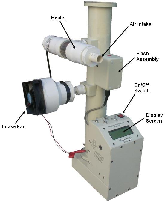
1 Mobile Nephelometer for Ambient PM 2.5 Monitoring OPERATIONAL PROCEDURES For use with the M903 Radiance Research Nephelometer and Garmin GPSMAP 60Cx Prepared by: Karla Poplawski, Eleanor Setton and Steeve Deschenes Spatial Sciences Research Laboratory Department of Geography University of Victoria January
2 -TABLE OF CONTENTS- PURPOSE... III RADIANCE RESEARCH M903 NEPHELOMETER... 1 GARMIN GPSMAP 60CX... 4 EQUIPMENT CHECKLIST... 5 VEHICLE SETUP (QUICK CHECK)... 6 Setting up the GPS:... 6 Setting up the Nephelometer:... 6 Connecting to Power:... 6 VEHICLE SETUP (COMPREHENSIVE)... 7 Setting up the Nephelometer:... 7 Connecting to Power DOWNLOADING THE DATA GPS Data Nephelometer Data DATA FORMATTING Preparing the Nephelometer Data Preparing the GPS Data COMBINING THE NEPHELOMETER AND GPS DATA SETTING UP THE HYPERTERMINAL CONNECTION FOR THE NEPHELOMETER ON A NEW COMPUTER SYNCHRONIZING THE NEPHELOMETER AND GPS CLOCKS CHANGING THE AVERAGING TIME AND FLASH RATE APPENDICES APPENDIX A - Mobile GPS Receiver/Data Logger GL-50S User s Manual Version 1.5 San Jose Navigation Inc, 2006 APPENDIX B - Operation Procedures M903 Nephelometer ROM Version DE Radiance Research, Seattle, WA ii
3 PURPOSE This document outlines the operational procedures for measuring ambient particulate matter (PM 2.5 ) concentrations with a Radiance Research M903 Nephelometer and a GARMIN GPSMAP 60Cx GPS unit, as developed by researchers at UVic s Spatial Sciences Research Lab. In addition to basic operational instructions, this manual provides additional documentation on downloading data, as well as preparing downloaded data for input into a Geographical Information System (GIS). Manuals for the GARMIN GPS and the Radiance Research M903 nephelometer are included for further reference in Appendices A and B. For technical assistance regarding general operation of equipment please contact: Eleanor Setton or Karla Poplawski University of Victoria Spatial Sciences Laboratory Phone: (250) elsetton@gmail.com or poplawski@alumni.uvic.ca iii
 3. Adaptor to Power Nephelometer Unit 4. Adaptor to Power Heater 5.")
4 RADIANCE RESEARCH M903 NEPHELOMETER Equipment Parts: 1. Nephelometer Unit Volt Inverter with adapter for car lighter/charger plug (may not look exactly like this) 3. Adaptor to Power Nephelometer Unit 4. Adaptor to Power Heater 5. Computer Connection Cables 6. Extension Cord 7. Copper Tubing with Funnel 8. Pipe Insulation Strip 1
5 Nephelometer Unit: 2


6 Nephelometer Ports Display Screen Scattering Coefficient (units m -1 ) Date Time Data avg. time constant Operation Mode (15 sec data averages) 3

7 GARMIN GPSMAP 60CX 2 Download Cable Not Shown 4
8 EQUIPMENT CHECKLIST Make sure that the following equipment is on hand at the start of every data run: Nephelometer: Large plastic Tupperware bin Small plastic bin Nephelometer unit Power adaptors (2) Copper tubing Funnel Pipe insulation strip Extension cord Inverter with lighter/charger adapter Data download cable Assorted software SERIAL to USB cd and HYPERTERMINAL cd Bungee cords GPS: GPS unit Extra AA batteries Download cable MapSource software cd Other (Optional): Map and directions Duct tape Notepad and pen/pencil 5
9 VEHICLE SETUP (QUICK CHECK) Setting up the GPS: 1. Turn on the GPS. Once signal is acquired, check it is in track mode (menu tracks Track Log on) and setup for 15 second logging. 2. Find a secure place on the dashboard. Setting up the Nephelometer: 1. Connect the nephelometer to the power adaptor. 2. Connect the heater to the other power adaptor. (There is a special white connector on this one). 3. Plug both adaptors into extension cord. Secure with rubber bands if necessary. 4. Secure the nephelometer into the large plastic Tupperware bin using bungee cords to ensure it does not tip over. Place the adaptors alongside the nephelometer, letting the white extension cord hang out. 5. Place the nephelometer in the passenger or backseat. 6. Attach the copper tubing to the air intake attached to the heater. 7. Place the copper sample tube out the window. The funnel should be secured to the outside end using duct tape. Point the funnel down and slightly to the rear of the vehicle. Use the pipe insulation to keep cold air out of the vehicle. Connecting to Power: 1. Make sure the inverter and all the connectors are properly attached. 2. Plug the extension cord from the nephelometer into the 12 volt inverter. 3. Plug the inverter into the lighter socket of the vehicle. 4. Start the vehicle. 5. Turn on the inverter, and then switch on the nephelometer. Check to make sure that the nephelometer is ticking and that the fan is running. Check all connections to the intake tube. Use duct tape as required. 6. When finished driving the route, turn off the nephelometer and GPS. Turn off the inverter and the car engine. These directions are repeated on the following pages including reference pictures. Please refer to pages 7 to 16 for clarification of any of the instructions above. 6


10 Vehicle Setup (COMPREHENSIVE) Setting up the Nephelometer: 1. Connect the nephelometer to the power adaptor. 2. Connect the heater to the other power adaptor. There is a special white connector on this one: 7


11 Plug both adaptors into the extension cord. Secure with rubber bands if necessary. 3. Secure the nephelometer into the large plastic Tupperware bin using bungee cords to ensure it does not tip over. Place the adaptors alongside the nephelometer, letting the white extension cord hang out. 8


12 4. Place the nephelometer in the passenger or backseat. 5. Attach the copper tubing to the air intake attached to the heater. 9

13 6. Place the copper sample tube out the window. The funnel should be secured to the outside end using duct tape. Point the funnel down and slightly to the rear of the vehicle. Use the pipe insulation to keep cold air out of the vehicle. 10


14 Connecting to Power 1. Make sure the inverter and all the connectors are properly attached (see below, note may not look exactly the same): Into lighter socket 2. Plug the extension cord from the nephelometer into the 12 volt inverter. 11

15 3. Plug the inverter into the lighter socket of the vehicle. 4. Start the vehicle. 5. Turn on the inverter, and then switch on the nephelometer. Check to make sure that the nephelometer is ticking and that the fan is running. Check all connections to the intake tube. Use duct tape as required. 6. When finished driving the route, turn off the nephelometer and GPS. Turn off the inverter and the car engine. 12
16 DOWNLOADING THE DATA Before downloading any data from the GPS Unit or the Nephelometer, first create a folder on your computer where you will store your data. Always storing the data in a designated folder makes it easier to find later, and ensures that data remain organized. GPS Data Connect the GPS unit to the computer with the USB cable and turn on GPS. 1. Double click the MapSource icon on your computer. 2. Go to the Tracks tab and delete any existing tracks. 3. Click on Transfer Receive from device. A new window will open, and should quickly find the GPS device. Click on Tracks in the What to Receive box, then click Receive. A new window should open with the message transfer complete. Click OK. 4. You may see a number of ACTIVE LOG files. When you start out, the firsdt ACTIVE LOG is created. If the GPS looses signal, it closes the first LOG, and when signal is reacquired, a new ACTIVE LOG file is started. 5. To export the LOG files to a single text file, click on File Save As. A new window opens, allowing you to choose a save location, a new file name (i.e., GPS_date) and file type (use.txt). Once you have successfully saved the text file open it up (use Notepad or Excel) and check that the data are as expected. Then: 6. Close the MapSource software, do not save any changes. 7. On the GPS, in the Tracks menu, select Clear (enter) and confirm Yes. NOTE when there is no satellite signal, the Track Log will automatically be OFF. You will send the GPS_date.txt file to your GIS technician. 13
, or double click the Hyper Terminal icon on your desktop and use File Open")
17 Nephelometer Data 1. Connect the nephelometer to an external power source (do not turn on). Do not plug in the heater! 2. Connect the download cable to the USB Port. 3. Open the saved nephelometer setting in the Hyper Terminal program (Programs/Accessories/Communications/Hyper Terminal/neph), or double click the Hyper Terminal icon on your desktop and use File Open to select the neph.ht file. 4. A blank screen will appear. Now turn on the nephelometer. Data will begin scrolling down the screen. Hit the s key once and the main menu will appear, as shown: 14
 and location of the text file that will be created. Select Browse and choose a location to save the file. 6. Click Start.")
18 5. Select the Transfer menu in the Hyper Terminal menu bar. Then select Capture Text to File. The program will ask you for a name (i.e., NEPH_Date.txt) and location of the text file that will be created. Select Browse and choose a location to save the file. 6. Click Start. The program will now store the information that subsequently appears on the screen as a text file in the location you specified. 7. Hit the s key once and then hit enter. This will download all the unmarked data in the nephelometer memory in short format. Data will begin scrolling down the screen. It will be saved to the text file you created. 8. When it has finished downloading select the Transfer menu in the Hyper Terminal menu bar and select Capture text > Stop. 15
, and n to the next prompt (you don t want to quit? y/n). The data are now marked at this point. 11. Type Q and then hit enter.")
19 9. Type? and hit return. This menu will appear again. 10. Type M to mark all the data as read and then hit enter. When you do this, you will be prompted twice. Answer y to the first prompt (mark all records as read y/n), and n to the next prompt (you don t want to quit? y/n). The data are now marked at this point. 11. Type Q and then hit enter. The nephelometer will now go into data-logging mode again. You should hear it ticking. You can now turn the nephelometer OFF. When it is turned on again it will automatically begin logging data. 12. Close the Hyper Terminal program. At the prompt, you can choose to save or not save the session file. The text file you created has already been automatically saved in the location you specified, so it is not necessary to save it again. As a check, open the text file you just saved your data to, to make sure that the data did indeed download. If not, you may have to try downloading it again. Use Notepad or WordPad to open the.txt file. An example of what it should look like is provided on page 25 of the manual. The NEPH_Date.txt file can now be sent on to a GIS technician for further analysis. 16


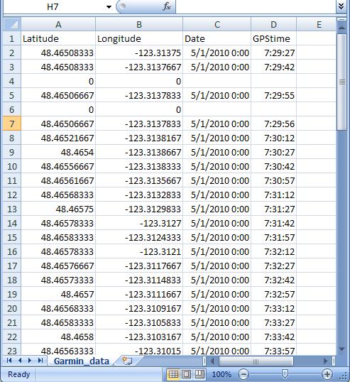
20 DATA FORMATTING The text files which were created in the last section will look like the pictures below once you open them. Clearly, they require some formatting and explanation in order to be useable. This section will describe how to open and manipulate the files in Excel to prepare them for use in a Geographic Information System (GIS). Nephelometer Data GPS Data 17


21 Preparing the Nephelometer Data 1. Open the NEPH_Date.txt file using Excel. To do this, first start Excel, then select File>Open. Find the nephelometer text file you saved. The Text Import Wizard opens. In the first screen, choose Delimited, click next. In the second screen, choose Space, click finish. There may be a few rows of general text that can be deleted, and often the first several rows of nephelometer data should be deleted, as these were captured right when the nephelometer was turned on and may not be accurate. 18

 you would like the new row inserted above and selecting insert from the menu that appears. 3.")
22 2. Delete the first column, and the last four columns (see figure below delete columns shown as DELETE). Do this by right-clicking the letter above the column you want to delete and selecting delete from the menu that appears. Insert a row at the top and add headings to the remaining columns, as displayed in the image below. Do this by right-clicking the number of the row (in the far left of the window) you would like the new row inserted above and selecting insert from the menu that appears. 3. Convert the BackScatter to PM_25: add the heading in the right-most column, add the following equation: =((G2*100000)-0.01)/0.28 to the first cell in the PM_25 column, then double-click the lower right corner of the cell. This should automatically put the equation in the remaining cells in the column. 4. Save the spreadsheet as NewName.xls and minimize. Double Click 19


23 Preparing the GPS Data 1. In Excel, open the GPS_Date.txt file. The Text Import Wizard opens. In the first screen, choose delimited, and click finish. Before doing any re-formatting, save this file with a new name (i.e., GPS_Date_formatted.txt). 20
.")
24 2. Remember, you may have a number of ACTIVE LOG files, if you lost GPS signal at any point. Each ACTIVE LOG file will be listed in the spreadsheet. You only need to keep the rows that start with Trackpoint and the Header row above the first Trackpoint row (rows to delete are colored grey in the figure below). Keep an empty row between the data for each ACTIVE LOG file, as this will help you to find time gaps later when you are matching the GPS data to the nephelometer data. 3. Delete all but the Position and Time columns. Now, you ll need to reformat these two columns to end up with a Latitude, Longitude and Time that shows the seconds. Insert five new columns to the right of the Position column Select the Position column, and then the Data Text to Columns tool. A new window will open. Choose fixed width and click on Next. 21

25 Add break lines as shown and click Finish: Delete unnecessary rows (shown in grey below): 22
 to the right of column B, and enter the following equation into cell C2: =A2+(B2/60) Then, add a new column to the left of column E (called Longitude), and enter")
26 The first two columns contain the latitude coordinates the first is the degrees, the second is minutes.seconds. These need to be combined into degrees.minutes (commonly called decimal degrees). Insert a new column (called Latitude) to the right of column B, and enter the following equation into cell C2: =A2+(B2/60) Then, add a new column to the left of column E (called Longitude), and enter the following equation into cell F2: =D2+(E2/60))*-1 Fill the remaining cells with these equations highlight the first cell with the equation, go to the bottom of the column and shift-click on the last cell this should select all the cells in the column, then hit ctrl-d this will copy the equation all the way down. Copy and paste values, so when we delete columns A, B, D and E, the final values will remain in columns C and F select the entire C column, then click ctrl-c to copy, and then paste paste special values. Do the same for column F. Finally, use the text-to-columns tool to split the date and time. Highlight the Time column, click on data text to columns, and when the new window opens, select fixed width and click next 23

27 Add break lines as shown, and click finish. Rename the columns as appropriate, and save!! 24
28 25


29 COMBINING THE NEPHELOMETER AND GPS DATA 1. Finally, we are ready to combine the nephelometer and GPS data. Find the first common time in the nephelometer file and in the GPS file Nephelometer data: GPS data (note this may not look exactly the same as your spreadsheet): 12:07:00 PM 2. Delete the rows in the nephelometer or GPS file that do not match at the beginning. For example, you may have turned on the nephelometer before the GPS, or the GPS may have started logging before you turned on the nephelometer. 26


30 delete 3. Select all the columns in the GPS file, and Copy 4. Go to the nephelometer file and put your cursor in the first empty cell in the first empty column use Paste Special, the choose Values and click OK. 27


31 5. Now you should have all the records for the nephelometer and the GPS in one file save this as Final_Data_Date.xls Go to the bottom of the file and check to make sure the time is still matching. Sometimes the GPS loses signal, or perhaps the nephelometer was turned on/off during the run. You ll have to adjust accordingly: Look for the first place where the mismatch occurs. Usually it is easiest to maximize the Excel window and spreadsheet, start at the top of the file, check the last row visible if the nephelometer time and GPS time match, click the scroll slider on the right to advance a page, and so on. If the last row visible does not match, find the first record in that page where the mismatch starts. Also, if you left a blank row in the GPS file between each ACTIVE LOG file, then you should be able to easily see where mismatches might occur. 28


32 EXAMPLES: Missing nephelometer data! Does not match GPS times. In this case, delete the extra GPS data to match up the times with the nephelometer data. Select the rows you want to delete, right click delete and shift cells up: 29


33 Continue this process until the data match up: They now match! Finally, delete any extra rows at the bottom that do not have both nephelometer and GPS data. Delete extra Rows! 6. Do a little data quality check: Sometimes the nephelometer will record a negative value delete these rows as they indicate a level at or below the detection limit, or unstable readings just after turning on the equipment. 30
34 3. SAVE. This file can now be easily converted for mapping using a geographic information system. 31

35 SETTING UP THE HYPERTERMINAL CONNECTION FOR THE NEPHELOMETER ON A NEW COMPUTER 1. Install the SERIAL to USB driver from the CD in the software package. 2. From the Start Menu select All Programs > Accessories> Communications > Hyper terminal, as displayed below. 32


36 3. You will be prompted whether you would like to establish a new connection. Give the connection a name, such as neph and select an icon. Then click ok. 4. Next, choose the COM port which corresponds to the USB connection on your computer which you will be plugging the nephelometer into. Click ok. 33


37 5. When asked to specify the properties about the selected COM port, choose 9600 as the appropriate Bits per second. Then click ok. 6. Exit the HyperTerminal program. You will be asked if you want to disconnect now. Select Yes. 6. The program will ask if you want to save the neph connection. Click Yes. 34

38 7. By choosing to save the neph connection, you will have added the neph icon under the Hyperterminal menu: You can now access the neph connection by going to the Start Menu > All Programs > Accessories > Communications> HyperTerminal > neph. Or you can create a shortcut for the desktop, as described next. 35

39 8. Right click on neph and select Create Shortcut from the drop-down menu that appears: 36
.")
40 9. There will now be another icon in the HyperTerminal menu, called Shortcut to neph. Click on the shortcut, and holding the mouse button down, drag it onto the desktop (as shown below). To access the HyperTerminal program now, all you have to do is double-click the icon on the desktop. 37
.")

41 SYNCHRONIZING THE NEPHELOMETER AND GPS CLOCKS The GPS unit receives very accurate times from the satellite signal, but the nephelometer s internal clock may slowly lose time. Set the nephelometer time once a month or so using the following procedure: 1. Go to the NIST website ( The following screen will appear 2. Click on the Pacific link below the map. This is Pacific Standard Time. The following screen will appear: 3. Connect the nephelometer to an external power source, but don t turn it on yet. Do not plug in the heater! 4. Connect the serial port between the nephelometer and a computer (use a USB adaptor if necessary. 38
42 5. Open the saved nephelometer setting in Hyper Terminal (Programs/Accessories/Communications/Hyper Terminal/neph). Or double-click the Hyper Terminal icon on the desktop. 6. A blank screen will appear. Turn on the nephelometer. Data will begin scrolling down the screen. Hit s once and the main menu will appear, as shown: 7. Arrange your computer screen so that both the UTC website is visible and the Hyper Terminal Screen is active and visible. The UTC time is shown to the closest second, whereas the nephelometer clock is set to the closest minute (although it displays seconds on the screen and in the logged file). 8. To set the nephelometer clock, on the Hyper Terminal screen type T YYMMDDhhmm. In the example below, if you want to set the clock to 3:07 AM on Dec 29, 2004 you type T


43 9. Hit return at the instant that the UTC time reaches the appropriate minute. 10. The current nephelometer time will be shown on the screen at that instant, as shown in the example below: 11. Type Q and then hit enter. The nephelometer will now go into data-logging mode again. You should hear it ticking. You can now turn the nephelometer OFF. When it is turned on again it will automatically begin logging data. 12. Close the Hyper Terminal program. At the prompt, you can choose to save or not save the session file. You do not need to save. When you turn the nephelometer back on again, the nephelometer display will show the current time (as GMT) and the datalogger will begin logging with this time. 40
44 CHANGING THE AVERAGING TIME AND FLASH RATE It may be desirable on occasion to change the averaging time period for stored averages. For instance, an averaging time of 15 seconds, 5 minutes, or 15 minutes might be more suitable for particular applications than others. If wishing to change the averaging time, please refer to pages of the official M903 Nephelometer Operation Procedures manual. The following steps provided below offer a summary of how to change the nephelometer settings for different averaging periods: 1. Connect the nephelometer to an external power source (do not turn on). Do not plug in the heater! 2. Connect the download cable to the USB port. 3. Open the saved nephelometer setting in the Hyper Terminal program (Programs/Accessories/Communications/Hyper Terminal/neph) or double click the Hyper Terminal icon on the desktop. 4. A blank screen will appear. Now turn on the nephelometer. Data will begin scrolling down the screen. Hit the s key once and the main menu will appear. 5. Type in z and hit enter to enter the data logger mode. 6. To change a value, type the command letter, then a space and then the new value and hit enter. For example, to change the E parameter to 25 and the H parameter to 15 type: E 25 H 15 and hit enter 7. Hit enter again to return to the main menu. 8. Type Q and then hit enter. The nephelometer will now go into data-logging mode again. You should hear it ticking. You can now turn the nephelometer OFF. When it is turned on again it will automatically begin logging data. 9. Close the Hyper Terminal program. At the prompt, you can choose to save or not save the session file. You do not need to save. The following table represents the settings necessary for a variety of different averaging times: Item 15 sec. 1 min. 5 min. 10 min. 15 min. A B C D E F G H
Centroid Snet 2. Battery Management Software. User Manual V1.1. Eagle Eye Power Solutions, LLC Keeping an Eye on Your Critical Power!
 Eagle Eye Power Solutions, LLC Keeping an Eye on Your Critical Power! Centroid Snet 2 Battery Management Software User Manual V1.1 www.eepowersolutions.com Tel: 1-877-805-3377 info@eepowersolutions.com
WiFi Hints & Tips. Contents. WiFi Hints and Tips 1. Page No. Section No. Title
 WiFi Hints & Tips Contents Page No. Section No. Title Section.0 System Set-Up 3 Section. Sensor Set-Up 4-5 Section. Sensor Set-Up (Configuring Network) 6-9 Section.3 Sensor Set-Up (Configuring Settings)
STEMSEL Beginners Project 1: Alarm System
 STEMSEL Beginners Project 1: Alarm System Problem How can we use microchips to protect our valuables? How can a microchip know if there is a thief and what can it do when it detects one? Background Have
Manage Alarms. Before You Begin. NTP-E57 Document Existing Provisioning CHAPTER
 CHAPTER 9 Manage Alarms This chapter provides procedures required to view and manage Cisco ONS 15600 alarms and conditions. Cisco Transport Controller (CTC) detects and reports SONET alarms generated by
Manage Alarms. Before You Begin CHAPTER
 CHAPTER 9 Manage Alarms This chapter provides procedures required to view and manage Cisco ONS 15600 alarms and conditions. Cisco Transport Controller (CTC) detects and reports SONET alarms generated by
ThermoBarScan TM Electronics UK Ltd INSTRUCTION BOOKLET
 ThermoBarScan TM Electronics UK Ltd INSTRUCTION BOOKLET Model: MM7100-2D Index Introduction 1 PC Setup 2-3 Bluetooth Setup 4-5 Discovery 6 USB Setup for USB instruments 7 Setting Instrument Parameters
Chapter 6. Alarm History Screen. Otasuke GP-EX! Chapter 6 Alarm History Screen 6-0. Alarm History Screen 6-1. Display Alarm History in List 6-2
 Chapter 6 Alarm History Screen Alarm History Screen 6- Display Alarm History in List 6-2 Let s Display Alarm History. 6-3 Read Data when Alarms Occur 6-2 Let s Read Data when Alarm Occur. 6-3 Let s Edit
Before you install ProSeries Express Edition software for network use
 Before you install ProSeries Express Edition software for network use The following pages describe system requirements and other information you need to know before installing ProSeries Express Edition
Temperature Monitoring, Operation and Maintenance of Research Freezers and Refrigerators SOP-TMOMRFR-01
 Standard Operating Procedure Temperature Monitoring, Operation and Maintenance of Research Freezers and Refrigerators SOP Number: SOP-TMOMRFR-01 Category: Lab Process Supersedes: N/A Effective Date: December
PHD Dolphin Installation
 Summary This document is intended to provide a user with instructions on installing the hardware on a Windows computer 2. Download the Dolphin USB driver by holding down the CTRL key and left clicking
Sirius Technologies, Inc.
 Model#: ST501 CO2/Temp/RH Indoor Air Quality Meter Users Manual Page 1 TABLE OF CONTENTS FEATURES & SPECIFICATIONS... 3 WHAT S IN THE BOX... 7 START UP AND GENERAL OPERATION... 8 Recording and Datalogging...
NYS Vaccines for Children (VFC) Program Fridge-Tag 2L Data Logger: Implementation and User Guide
 Program Fridge-Tag 2L Data Logger: Implementation and User Guide") NYS Vaccines for Children (VFC) Program Fridge-Tag 2L Data Logger: Implementation and User Guide Contents Purpose... 2 Equipment Checklist... 2 Calibration Certificates... 3 Setup... 4 Fridge-Tag 2L Glycol/Probe
NYS Vaccines for Children (VFC) Program Fridge-Tag 2L Data Logger: Implementation and User Guide Contents Purpose... 2 Equipment Checklist... 2 Calibration Certificates... 3 Setup... 4 Fridge-Tag 2L Glycol/Probe
Installing ProSeries 2005
 Installing ProSeries 2005 The following instructions will walk you through Installing and Launching ProSeries 2005. Before you begin your installation, it is very important to make note of the following
rvm4c Installation Guide Remote Video Module
 rvm4c EN Installation Guide Remote Video Module rvm4c Installation Guide Installation Diagrams EN 2 Installation Diagrams for the Transmitting Unit rvm4c Installation Guide Basic Hardware Installation
CRIME. Manufacturing And Minor Inventions CRIME. Control Room Integrated Monitoring Environment
 Control Room Integrated Monitoring Environment INDEX 1. Requirements for software. 2. Installation Instructions. 3. How to Register your Software. 4. Start Using... 5. Operating Instructions. 6. Screen
Installing ProSeries 2004
 Installing ProSeries 2004 The following instructions will walk you through Installing and Launching ProSeries 2004. Before you begin your installation, it is very important to make note of the following
Ambient Temperature/ Relative Humidity & Dew Point Temperature Sensors to USB Output. Model LFS108B
 Ambient Temperature/ Relative Humidity & Dew Point Temperature Sensors to USB Output Model LFS108B Copyright 2018 - LLC. All rights reserved. Table of Contents Quick Start... 3 1- Introduction... 4 2-
Procidia iware AlarmWorX32. AlarmWorX32 Viewer January 2010
 Procidia iware AlarmWorX32 AlarmWorX32 Viewer Siemens Protection AG 2008. notice All / Copyright rights reserved. notice Introduction / Contents Procidia iware is an operator interface software designed
Ion Gateway Cellular Gateway and Wireless Sensors
 Page 1 of 9 Account & Network Setup If this is your first time using the Ion Gateway online system site you will need to create a new account. If you have already created an account you can skip to the
Welcome to MultiSight TM Vision Sensor Hands-On Lab
 Welcome to MultiSight TM Vision Sensor Hands-On Lab About This Hands-On Lab Welcome to the MultiSight TM Vision Sensor Hands-On Lab! This session provides you with an opportunity to explore the functionality
PULSE OXIMETER PACKAGE
 instrumentation and software for research PULSE OXIMETER PACKAGE CANL-425SV-A USER S MANUAL DOC-095 Rev. 1.6 Copyright 2012 All Rights Reserved Med Associates Inc. P.O. Box 319 St. Albans, Vermont 05478
[ [ ADMIN PANEL USER GUIDE
 [ [ ADMIN PANEL USER GUIDE ADMIN PANEL USER GUIDE 2 Contents Logging In & Systems Overview 3 System Details 5 Analytics 6 View Alarms 8 Manage Alarms 9 Create Alarms 10 Device Reporting Alarm 11 Monthly
Instruction manual MTL process alarm equipment. October 2016 CSM 725B rev 2 MTL RTK 725B. Configuration Software Manual
 Instruction manual MTL process alarm equipment October 2016 CSM 725B rev 2 MTL RTK 725B Configuration Software Manual SECTION 1 - INTRODUCTION... 5 Basic Requirements... 5 SECTION 2 - SOFTWARE INSTALLATION...
PowerLogic ION Setup Meter Configuration Software Configuration Guide
 PowerLogic ION Setup Meter Configuration Software Configuration Guide 70002-0293-03 12/2010 Conventions Used in this Manual This section describes the symbols and terminology used in this guide. Symbols
Operation Manual Fighter ProVision Software. Version: 0.0 Revision: 1
 Operation Manual Fighter ProVision Software Version: 0.0 Revision: 1 TABLE OF CONTENTS 1. Introduction 5 2. Software Installation 5 3. PC Users 6 3.1 Introduction 6 3.2 Default Code 6 3.3 Edit PC User
HBC-4301 Hot Bonding Controller. Operators Manual
 HBC-4301 Hot Bonding Controller Operators Manual January, 2006 TABLE OF CONTENTS TABLE OF CONTENTS... 1 1. GETTING GOING FAST... 7 2. INTRODUCTION... 9 3. SPECIFICATIONS... 11 3.1 HARDWARE SPECIFICATIONS...
HERCULES 6 GRAPHICS SYSTEM
 HERCULES 6 GRAPHICS SYSTEM USER MANUAL Protec Fire Detection PLC, Protec House, Churchill Way, Nelson, Lancashire, BB9 6RT. Telephone: +44 (0) 1282 717171 Fax: +44 (0) 1282 717273 Web: www.protec.co.uk
Manage Alarms. Before You Begin CHAPTER
 CHAPTER 7 This chapter explains how to view and manage the alarms and conditions on a Cisco ONS 15310-CL. Cisco Transport Controller (CTC) detects and reports SONET alarms generated by the Cisco ONS 15310-CL
Manage Alarms. Before You Begin CHAPTER
 CHAPTER 9 This chapter explains how to view and manage the alarms and conditions on a Cisco ONS 15310-CL and Cisco ONS 15310-MA. Cisco Transport Controller (CTC) detects and reports SONET alarms generated
TV2 Clean Room Monitor
 TV2 Clean Room Monitor 1. The Care and Use guide for your TV2 Clean Room Monitor can be downloaded here: www.e2di.com/usersguides.html Please print out the Users Guide. Although you should use the Users
THERMO BUTTON HYGRO BUTTON The smallest temperature and humidity loggers in the world!
 THERMO BUTTON HYGRO BUTTON The smallest temperature and humidity loggers in the world! FOR ALL YOUR TEMPERATURE AND HUMIDITY CONTROLS, PRODUCT TRACKING, TRANSPORT, STORAGE CONTROLS, HACCP! Small, rugged,
725B Configuration Software Manual
 725B Configuration Software Manual REV DATED DESCRIPTION AUTHOR APPROVED 0 09-03-10 First Issue P.Cartmell Page 1 of 80 SECTION 1 - SOFTWARE INSTALLATION... 5 725B ConfigurationSoftware Installation...
Manage Alarms. Before You Begin CHAPTER
 CHAPTER 9 Manage Alarms This chapter contains the procedures for viewing and managing the alarms and conditions on a Cisco ONS 15454 SDH. Cisco Transport Controller (CTC) detects and reports SDH alarms
ocbridge Plus SPECIFICATION 3. COMPONENTS Wireless sensors receiver, battery СR2032, manual, instalation CD.
 1 2 3 4 5 6 7 8 IN OFF ON + T S B J Т1 ocbridge Plus 1. FEATURES Wireless sensors receiver ocbridge is designated for connecting compatible Ajax devices to any third party wired central unit (panel) with
Thermostat Guide Online Guide Brighten Conservation Program. Personal Reference Guide. Brighten ithermostat
 Thermostat Guide Online Guide Brighten Conservation Program Personal Reference Guide Brighten ithermostat Thermostat Guide Online Guide Brighten Conservation Program Welcome to your new Brighten ithermostat
INDOOR CLIMATE OF A SINGLE ZONE
 IDA Indoor Climate and Energy Basic Course INDOOR CLIMATE OF A SINGLE ZONE Guide Copyright EQUA Simulation AB February 2018 Purpose This is the first part of the IDA ICE basic course 1, where you get started
BST-MG08/09 Multi-gas Detecting Alarm. Manual Instruction
 BST-MG08/09 Multi-gas Detecting Alarm Manual Instruction 1. Application: This product is designed to ensure safety for users who work in dangerous places. It s used for detecting CO, O2, H2S, CH4 simultaneously
i-vu CCN 4.0 Owner s Guide
 i-vu CCN 4.0 Owner s Guide CARRIER CORPORAION 2007 A member of the United echnologies Corporation family. Stock symbol UX. 11-808-377-01 07/07 able of Contents ACCESSING YOUR SYSEM... 3 YOUR SYSEM DEAILS...
Ontech GSM 9040/50. Reference Manual English -1 -
 Ontech GSM 9040/50 Reference Manual English -1 - Content Welcome... 5 This manual... 5 Text styles... 5 Support... 5 Disclaimer... 5 Overview... 6 Accessories... 6 External temperature sensor 9901... 7
UTRED day Logger with display
 UTRED30-16 30 day Logger with display Technical User Manual Published September 2018 Copyright LogTag Recorders, 2018 Contents Safety Information... 3 Liability... 3 Battery Life... 3 Disclaimer... 3 Typographical
Table of Contents. Part I SAFETY MESSAGE TO INSTALLERS OF EMERGENCY WARNING EQUIPMENT 2 Part II Vehicle Operation 4. Part III Safety Messages 13
 Manual I SS2000 TouchScreen Installation Guide Table of Contents Foreword 0 Part I SAFETY MESSAGE TO INSTALLERS OF EMERGENCY WARNING EQUIPMENT 2 Part II Vehicle Operation 4 1 Installing the... SS2000 TouchScreen
TV2 Room Pressure Monitor Quick Start Guide
 TV2 Room Pressure Monitor Quick Start Guide 1. The Care and Use guide for your TV2 Room Pressure Monitor can be downloaded here: www.e2di.com/usersguides.html Please print out the Users Guide. Although
Subcooling is defined as the point at which liquid is cooled below it s condensing temperature. Example: Refrigerant R404A
 Installation & Service Manual S E C T I O N 26 Enviroguard III ENVIROGUARD III is a patented refrigerant control system that utilizes floating head technology (Nature s Cooling). The amount of liquid refrigerant
Manage Alarms. Before You Begin CHAPTER
 CHAPTER 8 Manage Alarms This chapter contains the procedures for viewing and managing the alarms and conditions on a Cisco ONS 15454. Cisco Transport Controller (CTC) detects and reports alarms generated
CompleteView Alarm Client User Manual. CompleteView Version 4.6.1
 CompleteView Alarm Client User Manual CompleteView Version 4.6.1 Table of Contents Introduction... 1 Overview...2 System Requirements...2 Configuration... 3 Starting the Alarm Client...3 Menus...3 File
Dashboard for Windows V1.1.0
 User manual Dashboard for Windows V1.1.0 TBS Electronics BV De Factorij 46 1689 AL Zwaag The Netherlands www.tbs-electronics.com COPYRIGHT 2009 (rev1e) - 1 - TABLE OF CONTENTS 1. INTRODUCTION......................
Operations Manual TS400. Test Station for G450/G460 Gas Detector
 TS400 Test Station for G450/G460 Gas Detector Operations Manual 1194 Oak Valley Dr, Ste 20, Ann Arbor MI 48108 USA (800) 959-0329 (734) 769-0573 www.goodforgas.com GfG Products for Increased Safety Congratulations
Weather Message Net Quick Start Guide Version 4
 Weather Message Net Quick Start Guide Version 4 The following guide will take you through the process to install and set up Weather Message. It is broken down into two sections, Software Installation and
Millennium Xtra. Millennium ATMA setup and configuration guide. May Millennium Group, Inc.
 Millennium Xtra Millennium ATMA setup and configuration guide May 16 2017 Millennium Group, Inc. 16 Tech Circle Natick, MA 01760 P: 508-655-1340 F: 508-651-2902 Millennium ATMA setup and configuration
Avigilon Control Center System Integration Guide
 Avigilon Control Center System Integration Guide with Picture Perfect 4 INT-PP4-A-Rev1 Copyright 2012 Avigilon. All rights reserved. No copying, distribution, publication, modification, or incorporation
Experion PKS Operator Course EXP01R201 06/2004 Rev 01
 Experion PKS Operator Course EXP01R201 06/2004 Rev 01 COURSE: Experion PKS Operator Course REVISION: 10 June, 2004 Honeywell IAC courseware is subject to change without notice. Honeywell IAC assumes no
Halton SAFE / 7.14 user guide and installation instructions
 Halton SAFE / 7.14 user guide and installation instructions VERIFIED SOLUTIONS BY H A LTO N Enabling Wellbeing Table of contents 1 System description 3 2 User Accounts 4 3 Main menu 7 3.1 Main menu - Change
Alarm Coordination Connected Components Building Block. Quick Start
 Alarm Coordination Connected Components Building Block Quick Start Important User Information Solid state equipment has operational characteristics differing from those of electromechanical equipment.
Patriot Systems Limited
 COPYRIGHT 1997 - The Patriot Systems Ltd. Patriot Alarm Monitoring Automation Package is licensed for use on one computer, by the original person, or company, or organization whose name is registered with
Alarm Client. Installation and User Guide. NEC NEC Corporation. May 2009 NDA-30364, Revision 9
 Alarm Client Installation and User Guide NEC NEC Corporation May 2009 NDA-30364, Revision 9 Liability Disclaimer NEC Corporation reserves the right to change the specifications, functions, or features,
Before you install ProSeries software for network use
 Before you install ProSeries software for network use The following pages describe system requirements and other information you need to know before installing ProSeries software for network use. Important:
SC-F3G User Manual 1.0
 SC-F3G User Manual 1.0 Table of Contents 1. Introduction... 3 2. Functions... 3 3. Features... 3 4. Package Contents... 3 5. Device Configuration... 4 6. Status LED signals... 5 7. Before You Start...
MultiSite Manager. Setup Guide
 MultiSite Manager Setup Guide Contents 1. Introduction... 2 How MultiSite Manager works... 2 How MultiSite Manager is implemented... 2 2. MultiSite Manager requirements... 3 Operating System requirements...
USER MANUAL DexTempTM 1000 Temperature Monitor (P/N: IR-1001) DexTempTM 1000 USB Non-Contact Temperature Monitor. User Manual.
 DexTempTM 1000 USB Non-Contact Temperature Monitor. User Manual.") USER MANUAL DexTempTM 1000 Temperature Monitor (P/N: IR-1001) DexTempTM 1000 USB Non-Contact Temperature Monitor User Manual 8690 Rev B Update: 10/24/2013 1 Table of Contents 1 Introduction.. 3 2 Host
USER MANUAL DexTempTM 1000 Temperature Monitor (P/N: IR-1001) DexTempTM 1000 USB Non-Contact Temperature Monitor User Manual 8690 Rev B Update: 10/24/2013 1 Table of Contents 1 Introduction.. 3 2 Host
Figure 1. Proper Method of Holding the ToolStick. Figure 2. Improper Method of Holding the ToolStick
 CAN OBD READER REFERENCE DESIGN KIT USER GUIDE 1. Standard ToolStick Handling Recommendations The ToolStick Base Adapter and daughter cards are distributed without any protective plastics. To prevent damage
Kaleidescape Programming Manual for Elan Home Systems
 Kaleidescape Programming Manual for Elan Home Systems Rev.1, July 2008 Elan Templates v1.0 2007-2008 Kaleidescape, Inc. All rights reserved. Kaleidescape and the Kaleidescape logo are trademarks of Kaleidescape,
7:00AM 1:00AM ET 7:00 AM 12:00AM ET
 Agent Guide Homebase intouch Customer Service (877) NRT-HELP Help@HomebaseinTouch.com M-F: 7:00AM 1:00AM ET Weekends: 7:00 AM 12:00AM ET Version 1.1 October 2012 Contents What is Homebase intouch?... 4
C&K Software What s New. Commander II Version 3.0 Monitor II Version 3.0 Satellite II Version 1.0
 C&K Software What s New Commander II Version 3.0 Monitor II Version 3.0 Satellite II Version 1.0 C&K Software PC-based receiver with monitoring features Windows-based Remote programming software (Commander
Alarm Calendar Version 1.10
 Alarm Calendar Version 1.10 For Symbian S60 Phones The information in this document is subject to change without notice. No part of this document may be reproduced or transmitted in any form or by any
M3092 Programmer. User s Manual. M3096B-33 E Copyright 2017 SELCO
 User s Manual Copyright 2017 SELCO SELCO Betonvej 11 - DK-4000 Roskilde Denmark Phone: 45 7026 1122 - Fax: 45 7026 2522 e-mail: selco@selco.com www.selco.com Table of contents 1 INTRODUCTION...4 2 SOFTWARE
Setting up Homebase, Exporting and Importing time clock files into OptRight Online
 Business Payroll Services Payroll University Setting up Homebase, Exporting and Importing time clock files into OptRight Online Reference Guide This document walks you through the process of setting up
Patriot Systems Limited
 COPYRIGHT 1997 - The Patriot Systems Ltd. Patriot Alarm Monitoring Automation Package is licensed for use on one computer, by the original person, or company, or organisation whose name is registered with
Specifications Minimum Typical Maximum Unit
 Temperature Probe Data Logger with LCD and USB Interface ORDERING INFORMATION Standard Data Logger (Data Logger, 1m Thermistor Probe, Software on CD and Battery) Replacement Battery LASREC028 LASACC001
ComfortNet CTK04 Featuring the RedLINK Suite of Home Comfort Solutions
 ComfortNet CTK04 Featuring the RedLINK Suite of Home Comfort Solutions Agenda Comfort Advantage System Configurations Installing ComfortNet ComfortNet Control Set up Dehumidification and Defrost Settings
USER MANUAL USB Multi-Function Datalogger Model RHT35
 USER MANUAL USB Multi-Function Datalogger Model RHT35 Additional User Manual Translations available at www.extech.com Introduction Thank you for selecting the Extech multi-function, easy-to-use, portable
Avigilon Control Center 5 System Integration Guide
 Avigilon Control Center 5 System Integration Guide with Hirsch Velocity INT-HIRSCH-B-Rev1 2012 2014 Avigilon Corporation. All rights reserved. Unless expressly granted in writing, no license is granted
WeatherLink for Alarm Output Addendum
 WeatherLink for Alarm Output Addendum Introduction This Streaming Data Logger is designed to provide an electrical interface between a Vantage Pro or Vantage Pro2 weather station console or Weather Envoy
USB Multi Function Dataloggers. RHT30 Humidity/Temperature Datalogger. TH30 Dual Temperature Datalogger
 USER MANUAL USB Multi Function Dataloggers RHT30 Humidity/Temperature Datalogger TH30 Dual Temperature Datalogger Additional User Manual Translations available at www.extech.com Introduction Thank you
WORKING WITH MEP ELEMENTS Smart Sprinklers extension
 WORKING WITH MEP ELEMENTS Smart Sprinklers extension Smart Sprinklers application for Autodesk Revit MEP......allows designers to quickly distribute sprinklers in a model with a real time interference
Alarms and Events. Defining Alarm Conditions. Database-Generated Alarms
 9 Defining Alarm Conditions Database-Generated Alarms The LookoutDirect alarm service keeps track of error messages and any process elements you have defined alarm conditions for. You can define alarm
Diagnostics and Monitoring System WEB Tool 2. User Manual
 Diagnostics and Monitoring System 2 (Translation of the original documentation) User Manual S/N: Valid from: 01.05.2012 Rev.: 2.0 2 Rev. 1.... 1 1.1 General information... 1 1.1.1 Equipment... 1 1.1.2
Milestone SMI Intrepid II Perimeter Module 1.1 User s Manual
 Milestone SMI Intrepid II Perimeter Module 1.1 User s Manual Target Audience for this Document This document is aimed at system users and provides descriptions on how to install and maintain the Milestone
Quick Alert Remote (QA216R)
") Quick Alert Remote (QA216R) Description The QA 216 Remote is used by AT&T to monitor tower lights and turned down facilities. It is a 16-bit alarm unit used to transport discrete alarms from a remote location
Quick Alert Remote (QA216R) Description The QA 216 Remote is used by AT&T to monitor tower lights and turned down facilities. It is a 16-bit alarm unit used to transport discrete alarms from a remote location
Spacing Average distance between seeds in a given row of planted seeds. Results are expressed in inches.
 Purpose: The purpose of the Field Seed Spacing Template is to provide a tool to gather information on seeds that have been planted. The results provide a numerical evaluation of the plant population and
USER MANUAL S203. Controller for three circuits. - control for 2 heating circuits - 1 domestic hot water control. Saving energy, creating comfort
 USER MANUAL S203 Controller for three circuits - control for 2 heating circuits - 1 domestic hot water control Saving energy, creating comfort This user manual consists of two parts. Issues that are intended
Instruction Sheet THERMOCOUPLE DATA LOGGER WITH LCD DISPLAY AND USB INTERFACE
 Instruction Sheet OM-EL-USB-TC-LCD THERMOCOUPLE DATA LOGGER WITH LCD DISPLAY AND USB INTERFACE Thermocouple Data Logger with LCD ORDERING INFORMATION Standard Data Logger OM-EL-USB-TC-LCD (Data Logger,
Remote switching machines with a SMS text from your mobile phone! Remote Monitoring your assets in the worldwide by your mobile Phone!
 Remote switching machines with a SMS text from your mobile phone! Remote Monitoring your assets in the worldwide by your mobile Phone! GSM SMS Controller DCS-130 User Manual Ver 1.20 Date Issued: 14-9-2010
Running IGSS as an Operator, Part One
 Running IGSS as an Operator, Part One Contents Duration We want to see how a completed IGSS SCADA system appears to plant operator personnel to get an idea of the various elements in the system and how
Bacharach Bodyguard 4 User's Guide
 Bacharach Bodyguard 4 User's Guide This manual and the software described in it are copyrighted, with all rights reserved. Under the copyright laws, this manual or the software may not be copied, in whole
Installing ProSeries software for stand-alone use
 Welcome to ProSeries tax software For information about this topic... Look here... Getting ready Page 1 Installing ProSeries software for stand-alone use Page 1 Setting up the ProSeries program Page 3
Table of Contents. i-vu CCN Standard 4.2
 i-vu CCN Standard 4.2 Owner's Guide CARRIER CORPORATION 2009 A member of the United Technologies Corporation family Stock symbol UTX Catalog No. 11-808-381-01 7/13/2009 Table of Contents Accessing your
IXIUM. DVR Smoke Alarm. User Manual
 IXIUM DVR Smoke Alarm User Manual Contents Package Contents... 2 Before You Start... 2 Overview: Smoke Alarm... 3 Controls: Smoke Alarm... 3 On/Off Switch... 3 SD Card Slot (TF)... 4 USB: Syncing and Charging...
Avigilon Control Center System Integration Guide
 Avigilon Control Center System Integration Guide with Velocity INT-HIRSCH-A-Rev3 Copyright 2013 Avigilon. All rights reserved. No copying, distribution, publication, modification, or incorporation of this
Semi-automated scores of urbanization
 System Requirements Supported Operating Systems: Windows 8, Windows 7, Windows Vista Microsoft.NET Framework 3.5 (available for download: http://www.microsoft.com/enus/download/confirmation.aspx?id=21)
Before you install ProSeries software for network use
 Before you install ProSeries software for network use The following pages describe system requirements and other information you need to know before installing ProSeries software for network use. Important:
ND4000 Manual Marine Hydraulics
 ND4000 Manual Marine Hydraulics Version 1.0 May 2012 Page 1 Contents Line Counter Components... 3 Proximity Sensors... 3 Connecting the Proximity Sensors to the SSCD... 3 Fuse... 3 USB... 4 Computer Display...
Alarm User Guide IGSS Version 9.0
 Alarm User Guide IGSS Version 9.0 Table of Contents Chapter 1: The Alarm List 4 1.1 Introducing the Alarm List 4 Process alarms and 'IGSS Alarm' 4 How is an alarm identified? 4 Alarm characteristics 4
SCAN200E USER S MANUAL
 SCAN200E USER S MANUAL Code No. 2071 1052 rev. 1.4 Code No. 2071 1052 Rev. 1.4 Page 2/16 SCAN200E User s Manual Foreword This manual is for SCAN200E Controller running software version 2.03 or later. We
UNITY 2 TM. Air Server Series 2 Installation Manual. Version September 2012
 UNITY 2 TM Air Server Series 2 Installation Manual Version 1.12 September 2012 1. Installation...2 1.1. Tools required...2 1.2. Procedure...2 1.3. Requirement for a sample pump (U-ASPMP1 / U-ASPMP2)...8
Follett Performance Plus
 Follett Performance Plus touchscreen user guide The next level of control in undercounter refrigeration Controller Operation - Performance Plus touchscreen Use and care of the LCD Performance Plus touchscreen
Security Escort Central Console Software SE2000 Series
 Release Notes Security Escort Central Console Software SE2000 Series Table of Contents 1 Security Escort v2.18.1.0... 2 1.1 Enhancements... 2 1.2 Errors Fixed... 2 1.3 Known Limitations and Restrictions...
Lighting Xpert Insight User Manual
 Lighting Xpert Insight User Manual Table of Contents 1 About This Document... 3 1.1 Key Terms... 3 1.2 Related Fifth Light Documentation... 3 2 Lighting Xpert Insight Overview... 4 2.1 Key Features...
Sentient. Downloader Manual D4854
 Sentient Downloader Manual D4854 Dycon Ltd Tel: +44 (0)1443 471 060 Fax: +44 (0)1443 479 374 Cwm Cynon Business Park Mountain Ash CF45 4ER - UK www.dyconsecurity.com sales@dyconsecurity.com TABLE OF CONTENTS
Laptop / PC Programming Manual
 Laptop / PC Programming Manual Doc. # Fire PC Program rev B 01.07 This Document is property of Evax Systems, Inc. The Evax Fire Solutions Programmer Components 2 1.0 System Setup 4 1.1 Interface Setup
EL-USB-2-LCD+ High Accuracy Humidity, Temperature and Dew Point Data Logger with LCD
 High Accuracy Humidity, Temperature and Dew Point Data Logger with LCD ORDERING INFORMATION Standard Data Logger (Data Logger, Software on CD, Battery) Replacement Battery 99 Washington Street Melrose,