Static Pressure Alarm For Hazardous Location Fume Hoods
|
|
|
- Molly Watson
- 6 years ago
- Views:
Transcription

1 Static Pressure Alarm For Hazardous Location Fume Hoods Models: XPA Class 1, Division 1, Group C, D 120V/15A/60Hz Pressure range 0.07 to 0.15 in-wg XPA Class 1, Division 1, Group C, D 120V/15A/60Hz Pressure range 0.15 to 0.50 in-wg XPA1B-0715 Class 1, Division 1, Group B, C, D 120V/15A/60Hz Pressure range 0.07 to 0.15 in-wg XPA1B-1550 Class 1, Division 1, Group B, C, D 120V/15A/60Hz Pressure range 0.15 to 0.50 in-wg XPA XPA Class 1, Division 2, Group A, B, C, D 120V/15A/60Hz Pressure range 0.07 to 0.15 in-wg Class 1, Division 2, Group A, B, C, D 120V/15A/60Hz Pressure range 0.15 to 0.50 in-wg Contents: General Description Contents of box Installation Adjustment Operation Safety Specifications Warrantee statement Components Represented By: Holland Safety Equipment 726 McKinley Ave., Libertyville, IL Phone: Explosion Proof Alarm Rev.7 June 2014 page 1
2 General Description Intended for use in laboratories that are classified as a hazardous location, the explosionproof low pressure alarm provides continuous monitoring of the negative static pressure in the fume hood exhaust duct. During normal negative static pressure conditions, the alarm illuminates a green indicator LED. When static pressure in the exhaust duct is insufficient, an audible alarm sounds and a red LED indicator illuminates. To maintain the integrity of the certified explosion proof instrument enclosure, the functionality of the test/reset button is performed using a light sensor. Covering the light sensor momentarily acknowledges the alarm and silences the horn for 10 minutes. During periods of darkness, the alarm functions normally but the test/reset function is unavailable. An output relay is provided to signal a remote alarm if needed. An additional output relay is provided with normally closed and normally open contacts which may be used for connection to the building systems. This relay activates in the event of a loss of static pressure. Additionally, an input is provided which may be used by the building system to mute the alarm during periods of intentional exhaust shutdown or slow down. Alternately, a light based night setback function may be enabled through jumper configuration on the circuit board if enabled; the audible alarm will be muted during periods of darkness. All electrical housings as well as pressure switch are UL or FM approved for Class 1, Div 1, Groups B, C and D. XPA1 models are provided with a Class 1, Division 1, Group C and D buzzer. XPA1B models are provided with a Class 1, Division 1, Group B, C, D buzzer. XPA2 models are provided with a Class 1, Division 2, Group A, B, C and D. Box Contents: The box contains the following items: Control Box including main circuit board Operator Display unit Dwyer 1950G-00-B-120-NA pressure switch for models or 1950G-0-B-120-NA pressure switch for models Static pressure duct probe tube 15 feet of ¼ polyethylene tubing Federal Signal explosion proof horn 350WBX-120 for XPA2 models or 31X for XPA1 models or Edwards 878EX-N5 horn for XPA1B models Installation Installation consists of the following general steps: Mount the control box Mount the pressure switch Mount the operator display unit Explosion Proof Alarm Rev.7 June 2014 page 2


3 Mount the buzzer Wire the control box to the operator display panel Wire the control box to the pressure switch Wire the control box to the buzzer Wire 120v mains supply to control box The following steps must be completed after the hood has been installed and the exhaust system is operational and both exhaust and supply airflow for the laboratory has been properly balanced. Install the static pressure probe in the duct above the fume hood Connect tubing from the low pressure port on the pressure switch to the static pressure port Verify hood flow and adjust the pressure switch to the minimum setting which maintains a green indication Detailed Installation Instructions: In most cases it will be expedient to pre-assemble some or all of the wiring on the bench before mounting the enclosures to the fume hood therefore the sequence of work listed below may be modified as needed. All items must be mounted such that moving parts like the sash, sash counterbalance, chain or cable do not rub against them. Generally speaking it is not acceptable to penetrate the fume hood liner when mounting these items consult the fume hood manufacturer if in doubt. All items must be accessible for servicing in the future. Mount the control box The control box should be securely mounted on the roof of the fume hood using suitable fasteners. Mount the Pressure Switch The pressure switch should be securely mounted in a VERTICAL POSITION using suitable fasteners in accordance with the included instruction sheet (also available as Appendix A in this manual) Mount the Operator Display Unit The operator control panel is designed to be mounted to the face of the fume hood and should be accessible to the operator of the fume hood at all times. A moderate amount of ambient light is needed to provide access to the test/reset function. A bracket is provided for the installation of two, #8 sheet metal screws which should be oriented at the top. The conduit entry should be at the bottom and normally an elbow is used to allow the explosion proof cable to enter the hood side wall for routing to the main control panel. The circuit board may be removed for electrical connection by unscrewing the nuts located at 9 o-clock, 12 o-clock and 3 o- Explosion Proof Alarm Rev.7 June 2014 page 3
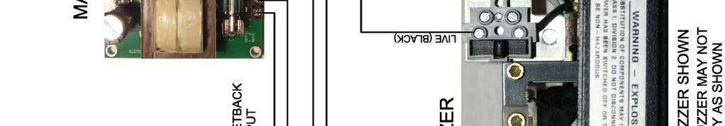
4 clock. See illustration at right indicating screws that must be removed. Take care not to damage the ambient light sensor. Should it be necessary to install the unit with the conduit entry at another position, the circuit board and face plate may be re-configured to whatever position is needed. Mount the Buzzer The buzzer should be securely mounted to the roof of the fume hood using suitable fasteners. Details on the buzzer are available in Appendix B. Wiring All Wiring must be performed by a licensed electrician in a manner acceptable to the local authorities and in accordance with the most recent edition of the National Electrical Code. In general type MC-HL cable and glands listed for a hazardous location can be used, but in some cases rigid conduit and listed sealing fittings will be required. 14 gauge wire is recommended (12 gauge may also be used) for connection between the control box and the buzzer and the pressure switch. The connection between the Control Box and the Operator Display Unit is low voltage and lighter gauge wire should be used if available The alarm system should be permanently connected to a 15A or 20A/120V circuit. Figure 1 shows connections that must be made for the XPA2 Class 1, Division 2 models. Connection for XPA1 and XPA1B Class 1, Division 1 models is the same with a slightly different buzzer which has two wires white for neutral and black for live. Ground wires are not shown note that ALL BOXES must be grounded in accordance with the NEC and local codes. For alarm installations making use of the remote alarm output or optional night setback mute input, it is necessary to connect the main control box to another junction box using a short length of multi-conductor cable or conduit with appropriate seals. This will allow for the connection of the additional cables needed to implement the remote alarm feature. Alternately, the alarm may be special ordered with additional ½ NPT threaded openings in the control box. At this time, determine if the light based night setback feature will be used. If so install jumper on J1 on the circuit board. If J1 is installed, the audible alarm will automatically be muted after the room is dark for 1 minute. As soon as light is restored, the audible alarm will be restored automatically. After wiring, each housing, including circuit boards must be re-assembled exactly as they were and covers must be installed and tightened. Explosion Proof Alarm Rev.7 June 2014 page 4


5 Explosion Proof Alarm Rev.7 June 2014 page 5
6 Install the Static Pressure Probe The included static pressure probe is suitable for ducts 8 diameter and larger. It should be located at least one duct diameter above the fume hood in a straight section of ducting. Drill a 5/16 diameter hole in the duct above the fume hood. Install the static pressure probe in the duct using the included foam rubber gasket and self-drilling sheet metal screws. Attach the ¼ polyethylene hose from the fitting on the static pressure probe to the LOW PORT on the pressure switch using the included adapter. Ensure that the hose is not allowed to chafe on any moving parts including the sash, counterweight and cables or chains. Leave the high port open. If the pressure switch is located in a space that is not at the same pressure as the laboratory, then connect suitable hose to the HIGH port and run this hose into the laboratory space. Adjusting the alarm set point The Airflow Monitor must be calibrated before first use and checked regularly thereafter. Fume hoods vary in design and performance. Because each hood installation and its airflow pattern is unique, this monitor must be calibrated in the field on the fume hood in which it is installed. WARNING Calibration of this instrument should only be performed by qualified personnel. Proper guidelines for monitoring any ventilation apparatus are established on the basis of toxicity or hazards of the materials used, or the operation conducted within the ventilation apparatus. Personnel calibrating the alarm must be completely aware of the regulations and guidelines specific to its application. If you need a reference on performing traverses on fume hoods, please consult the latest edition of ASHRAE 110 Method of Testing Performance of Laboratory Fume Hoods, section 6.2 Face Velocity Measurements. Tools Required 1. Calibrated thermo-anemometer rated for hazardous environments. 2. Small slotted screwdriver. Procedure 1. Double check installation to verify that the monitor, power supply, and any ancillary equipment are properly installed. 2. Allow at least 10 minutes for the pressure switch to warm up. 3. Determine the alarm set point. This is the condition where the monitor will indicate a low flow condition. The red LED on the Operator Panel will light at this point. Consult the facility s Industrial Hygiene Officer for the proper set point. NOTE: This device senses the duct static pressure. Different hoods may require different duct static pressure to generate the same face velocity. Explosion Proof Alarm Rev.7 June 2014 page 6
7 4. Set the sash at the working height and adjust the fume hood airflow to the low alarm set point (as determined in step 3, above). One method is to close the volume damper (if available) in the ductwork. This damper must be downstream of the static pressure probe. WARNING This method is only used as a temporary means of setting the low flow set point. Make certain that airflow is restored to the proper level after calibration. 5. Using a properly calibrated thermo-anemometer, determine the velocity through the face of the hood by taking a detailed velocity traverse. Divide the face area of the hood into equal partitions. One reading per square foot of face area is recommended for an accurate traverse. Compute the average velocity for this area. Temporarily adjust the airflow of the fume hood as in step 4 above until the average face velocity is near the desired low flow alarm set point. NOTE: The pressure switch response time may be as long as 10 to 25 seconds when the applied pressures are near the set point. 6. If the red LED is initially lit, slowly turn the adjustment screw on the pressure switch clockwise until the green LED lights and then slowly turn the adjustment screw counterclockwise until the red LED again lights. If the green LED is initially lit, slowly turn the adjustment screw on the pressure switch counter clockwise until the red LED lights. IMPORTANT: To allow for the delayed reaction of the pressure switch, these adjustments must be made in small increments, at intervals up to 25 seconds each. 7. Restore normal airflow to the fume hood. NOTE: Due to the hysteresis of the pressure switch, the sash of the fume hood may need to be nearly closed to generate sufficient duct static pressure to reset the pressure switch to a good flow (green LED lit) condition. Upon restoring the airflow to the normal level, drop the sash down to reset the alarm to a non-alarm status and then return the sash to the working height. The green LED should remain lit. 8. Verify the alarm setting by establishing a low flow condition (as in step 4). If the alarm does not activate, repeat steps 5 through 8. Adjusting Alarm Volume It is recommended that the volume of the horn be adjusted to suit the ambient noise level in the laboratory. Details on volume adjustment are contained in the buzzer manufacturer s literature at the end of this manual. It is essential to use hearing protection while working on these buzzers. Operation During normal operation, the static pressure alarm operator display panel should give a green indication. This indicates that the pressure switch is sensing negative pressure in the fume hood exhaust duct in the normal range as established by the calibration procedure. While the unit is indicating in the green, the audible and visible alarm may be tested by momentarily covering and uncovering the light sensor three times (within three seconds). The indicator lights will flash and the audible alarm will sound twice. In order Explosion Proof Alarm Rev.7 June 2014 page 7
8 to provide access to other functions, this test may be performed only once every 60 seconds. The alarm buzzer must be tested monthy. In the event that the alarm sounds, it is generally because a loss of static pressure has been detected in the fume hood exhaust. At this time, the fume hood sash should be lowered to re-establish adequate static pressure. If the alarm does not reset, it is likely that the exhaust system has failed. Stop using the fume hood for active experiments, close the sash and evacuate the laboratory if the chemicals or fumes pose an immediate hazard. If the low flow condition is expected and no hazard is present in the hood (such as during experiment set-up or tear-down) then the alarm may be temporarily silenced by momentarily covering and uncovering the light sensor. The temporary muting of the alarm will last for approximately 10 minutes after which time normal operation will resume. In the event that the fume hood will be decommissioned for an extended period of time, the alarm can be permanently muted by covering and uncovering the light sensor seven to eight times within a 30 second period. Successful completion of this procedure will result in both red and green LED s flashing three times. While the audible alarm is muted, the green or red led will be flashing as opposed to solid. The same procedure will re-enable the audible alarm. If the power supply to the alarm is interrupted, then it will reset to normal operation. Testing In order to ensure that the alarm system as a whole is functional, it must be fully tested at least yearly by turning off the exhaust system to ensure that the alarm will sound when a loss of airflow occurs. Ensure that there are no hazards in the fume hood during this test. Safety Before opening unit for servicing, ensure no hazardous or explosive fumes are present, disconnect power and lock-out. Explosion Proof Alarm Rev.7 June 2014 page 8
9 Specifications Voltage: Frequency: Current: Mains Breaker: Mounting: Alarm Pressure Range: Alarm relay output: Visual Indicators: Audible Indicator: Horn Silence: User Input: Wiring method: Calibration: Agency Listings: 120VAC 60 Hz 1A Switch/Breaker 15A Surface Mount 0.07 to 0.15 inches water for model 0.15 to 0.50 inches water for model Normally open and normally closed volt-free contacts Contacts rated 0.5A at 125 VAC / 1A at 24 VDC Green LED static pressure OK Red LED static pressure FAIL Intermittent Buzzer 94 db at 10 feet Temporary with 10 minute self-reset Permanent until re-enabled or power-cycle Optional darkness based automatic alarm mute Optional night setback input connections Alarm is silenced and tested through the use of an ambient light sensor located behind sealed window in explosion proof housing Installer supplies explosion proof wiring materials and glands. Single point pressure setting All housings FM or UL listed Specifications subject to change without notice Warranty LIMITATION OF WARRANTY AND LIABILITY The Manufacturer warrants the goods sold hereunder, under normal use and service as described in the operator's manual, shall be free from defects in workmanship and material for TWELVE (12) months, or the length of time specified in the operator's manual, from the date of shipment to the customer. This warranty period is inclusive of any statutory warranty. This limited warranty is subject to the following exclusions: The manufacturer does not provide additional warranty on major components manufactured by others - only the original manufacturer's warranty applies. Unless specifically authorized in a separate writing by manufacturer, the manufacturer makes no warranty with respect to, and shall have no liability in connection with, goods which are incorporated into other products or equipment, or which are modified by any person other than the manufacturer. The foregoing is IN LIEU OF all other warranties and is subject to the LIMITATIONS stated herein. NO OTHER EXPRESS OR IMPLIED WARRANTY OF FITNESS FOR PARTICULAR PURPOSE OR MERCHANTABILITY IS MADE. TO THE EXTENT PERMITTED BY LAW, THE EXCLUSIVE REMEDY OF THE USER OR BUYER, AND THE LIMIT OF THE MANUFACTURER S LIABILITY FOR ANY AND ALL LOSSES, INJURIES, OR DAMAGES CONCERNING THE GOODS (INCLUDING CLAIMS BASED ON CONTRACT, NEGLIGENCE, TORT, STRICT LIABILITY OR OTHERWISE) SHALL BE THE RETURN OF GOODS TO THE MANUFACTURER AND THE REFUND OF THE PURCHASE PRICE, OR, AT THE OPTION OF THE MANUFACTURER, THE REPAIR OR REPLACEMENT OF THE GOODS. IN NO EVENT SHALL THE MANUFACTURER BE LIABLE FOR ANY SPECIAL, CONSEQUENTIAL OR INCIDENTAL DAMAGES. THE MANUFACTURER SHALL NOT BE RESPONSIBLE FOR INSTALLATION, DISMANTLING OR REINSTALLATION COSTS OR CHARGES. No Action, regardless of form, may be brought against The manufacturer more than 12 months after a cause of action has accrued. The goods returned under warranty to the manufacturer s factory shall be at Buyer's risk of loss, and will be returned, if at all, at the manufacturer s risk of loss. Buyer and all users are deemed to have accepted this LIMITATION OF WARRANTY AND LIABILITY, which contains the complete and exclusive limited warranty of MANUFACTURER. This LIMITATION OF WARRANTY AND LIABILITY may not be amended, modified or its terms waived, except by writing signed by an Officer of MANUFACTURER. Explosion Proof Alarm Rev.7 June 2014 page 9

10 Components: Operator Panel Explosion Proof Alarm Rev.7 June 2014 page 10


11 Main Control Box Explosion Proof Alarm Rev.7 June 2014 page 11


12 Static Pressure Switch Static Pressure Probe Explosion Proof Alarm Rev.7 June 2014 page 12


13 Class 1, Division 2, Group A,B,C,D Buzzer Class 1, Division 1, Group C,D Buzzer Explosion Proof Alarm Rev.7 June 2014 page 13

14 Appendix A Explosion Proof Alarm Rev.7 June 2014 page 14

15 Explosion Proof Alarm Rev.7 June 2014 page 15
16 Appendix B Explosion Proof Alarm Rev.7 June 2014 page 16
17 Explosion Proof Alarm Rev.7 June 2014 page 17
18 Explosion Proof Alarm Rev.7 June 2014 page 18
19 Explosion Proof Alarm Rev.7 June 2014 page 19
20 Explosion Proof Alarm Rev.7 June 2014 page 20
21 Explosion Proof Alarm Rev.7 June 2014 page 21
22 Explosion Proof Alarm Rev.7 June 2014 page 22
23 Explosion Proof Alarm Rev.7 June 2014 page 23
24 Explosion Proof Alarm Rev.7 June 2014 page 24
25 Explosion Proof Alarm Rev.7 June 2014 page 25
26 Explosion Proof Alarm Rev.7 June 2014 page 26
27 Explosion Proof Alarm Rev.7 June 2014 page 27
28 Explosion Proof Alarm Rev.7 June 2014 page 28
29 Explosion Proof Alarm Rev.7 June 2014 page 29
Alnor AirGard 410HE Air Flow Monitor for Hazardous Environment Fume Hoods
 Air Flow Monitors Alnor AirGard 410HE Air Flow Monitor for Hazardous Environment Fume Hoods Owner s Manual LIMITATION OF WARRANTY AND LIABILITY (effective June 2011) Seller warrants the goods sold hereunder,
AFA 500 FUME HOOD ALARMS
 AFA 500 FUME HOOD ALARMS Operating and Instruction Manual 19/7/03 Model AFA 500 Built-in or Remote sensor 2 Relay inputs 1 Relay output Com port Used for alarm indication and monitoring on Fume Cupboards
Model 405 AIRGARD Fume Hood Monitor
 INSTALLATION AND MAINTENANCE INSTRUCTIONS Model 405 AIRGARD Fume Hood Monitor A TSI Company Model 405 AIRGARD Fume Hood Monitor Specifications Instrument Dimensions Instrument Weight Shipping Weight Green
FUME HOOD MONITOR ALNOR AIRGARD 200
 FUME HOOD MONITOR ALNOR AIRGARD 200 OWNER S MANUAL P/N 116670080, REV 09 SEPTEMBER 2014 LIMITATION OF WARRANTY AND LIABILITY (effective April 2014) (For country-specific terms and conditions outside of
AirGard 385 Fume Hood Monitor
 OWNER S MANUAL AirGard 385 Fume Hood Monitor A TSI Company AIRGARD 385 MONITOR SPECIFICATIONS Digital Display Display Units 3 digit, 7-segment liquid crystal display. Feet per minute () or meters per second
LABCONCO 1000 GUARDIAN DIGITAL MONITOR Operating and Instruction Manual
 LABCCO 1000 GUARDIAN DIGITAL MITOR Operating and Instruction Manual Model: Guardian 1000 / 1 Digital display 3 Relay inputs 3 Relay outputs Com port Used for alarm indication and monitoring on Fume Hoods
FUME HOOD MONITOR ALNOR AIRGARD 335
 FUME HOOD MONITOR ALNOR AIRGARD 335 OWNER S MANUAL P/N 116159255, REV 10 SEPTEMBER 2014 LIMITATION OF WARRANTY AND LIABILITY (effective April 2014) (For country-specific terms and conditions outside of
Model AV1LED Audio-Visual LED Light Installation and Maintenance Manual
 Model AV1LED Audio-Visual LED Light Installation and Maintenance Manual 2561528A REV. A 810 Printed in U.S.A. Warranty Seller warrants all goods for five years on parts and 2-1/2 years on labor, under
Model 9001EXP Alarm. NOTE TO INSTALLER: Please leave this information with the Maintenance Department. LIMITED WARRANTY
 INSTALLATION, OPERATION & MAINTENANCE INSTRUCTIONS 1455 Kleppe Lane Sparks, NV 89431-6467 (775) 359-4712 Fax (775) 359-7424 E-mail: haws@hawsco.com website: www.hawsco.com Model 9001EXP Alarm No. 2080203(24)
DWYER INSTRUMENTS, INC. P.O. BOX 373 MICHIGAN CITY, INDIANA 46360, U.S.A. Series 670 Hood Monitor. Bulletin AV-670
 Bulletin AV-670 Series 670 Hood Monitor Specifications - Installation and Operating Instructions DWYER INSTRUMENTS, INC. P.O. BOX 373 MICHIGAN CITY, INDIANA 46360, U.S.A. Phone: 219/879-8000 Fax: 219/872-9057
HVAC Controls Laboratory. Model EVERWATCH Face Velocity Monitor. Operation and Service Manual. P/N , Revision E October 2002
 HVAC Controls Laboratory Model 8610 EVERWATCH Face Velocity Monitor Operation and Service Manual P/N 1980154, Revision E October 2002 Model 8610 EVERWATCH Face Velocity Monitor Operation and Service Manual
CRITICAL ENVIRONMENT MONITOR ALNOR AIRGARD 350 CEM
 CRITICAL ENVIRONMENT MONITOR ALNOR AIRGARD 350 CEM OWNER S MANUAL P/N 116159359, REV 06 SEPTEMBER 2014 LIMITATION OF WARRANTY AND LIABILITY (effective April 2014) (For country-specific terms and conditions
installation, operation & Maintenance manual Floor-mounted Induction units
 installation, operation & Maintenance manual Floor-mounted Induction units built on innovation induction units- fmfby/ fmlby/ fmtby Floor-mounted induction units FMFBY, FMLBY, & FMTBY are designed for
MaxLite LED VAPOR TIGHT LINEAR FIXTURES
 A cost effective LED Vapor Tight Fixture features a full length polycarbonate lens and a one-piece white glass reinforced polyester (GRP) body. Designed to meet or exceed seven to 10 foot-candles at 8
M Series Fan Filter Units
 M Series Fan Filter Units Product Specifications... 2 Safety Instructions... 3 Receiving and Unpacking... 3 Pre-Installation Instructions... 3-4 Installation Instructions... 4 Electrical Installation Instructions...
Sentry LIQUID LEVEL CONTROLLER MODEL 120 OPERATING MANUAL.
 Sentry LIQUID LEVEL CONTROLLER MODEL 120 OPERATING MANUAL www.aquaticsentry.com TABLE OF CONTENTS 1. SAFETY PRECAUTIONS... 3 2. APPLICATION... 3 2.1 HIGH AND LOW LEVEL ALARM 2.2 PUMP DOWN CONTROLLER 2.3
Model 9001, Alarm
 INSTALLATION, OPERATION & MAINTENANCE INSTRUCTIONS 1455 Kleppe Lane Sparks, NV 89431-6467 (775) 359-4712 Fax (775) 359-7424 E-mail: haws@hawsco.com website: www.hawsco.com No. 2080202(27) Model 9001, 9001.5
MaxLite LED Round Pendant Highbay Series
 General Safety Information To reduce the risk of death, personal injury or property damage from fire, electric shock, falling parts, cuts/abrasions, and other hazards read all warnings and instructions
installation, operation & Maintenance manual Floor-mounted Induction units acb 30/35
 installation, operation & Maintenance manual Floor-mounted Induction units acb 30/35 built on innovation acb 30 & 35 Active Chilled Beam Models ACB30 & ACB35 are designed for installation in the ceiling
MaxLite LED MICRO-T PANEL
 ` Installation Instructions General Safety Information To reduce the risk of death, personal injury or property damage from fire, electric shock, falling parts, cuts/abrasions, and other hazards read all
Model Gas Alarm Panel APPLICABILITY & EFFECTIVITY. This manual provides instructions for the following Sierra Monitor products:
 Model 2102 Gas Alarm Panel APPLICABILITY & EFFECTIVITY This manual provides instructions for the following Sierra Monitor products: Model Description 2102-00 Alarm Panel 2 Channel 2102-01 Alarm Panel 2
SYSTEM CONTROL KIT Model: CK-41P
 SYSTEM CONTROL KIT Model: CK-41P READ THE INSTALLATION INSTRUCTIONS CAREFULLY & COMPLETELY BEFORE BEGINNING THE INSTALLATION! Designed for use with the SWG Series Power Venter for controlling Natural Gas
PRESSURA ROOM PRESSURE CONTROLLER MODELS 8630-SC 8630-PC
 PRESSURA ROOM PRESSURE CONTROLLER MODELS 8630-SC 8630-PC OPERATION AND SERVICE MANUAL P/N 1980243, REVISION J DECEMBER 2013 PRESSURA ROOM PRESSURE CONTROLLER MODELS 8630-SC 8630-PC OPERATION AND SERVICE
Sentry LIQUID LEVEL GAUGE MODEL 200 or 200C OWNER MANUAL REV 1.7 SEPT08 PAGE 1 OF 12
 PAGE 1 OF 12 TABLE OF CONTENTS PAGE 1. SAFETY PRECAUTIONS 1.1. Electrical shock 3 2. APPLICATION 3 3. INSTALLATION 3.1. Mount indoor alarm display 3.2. Mount the outdoor junction box 3.3. Install interconnecting
Laboratory Airflow Monitors & Controls TYPE C STANDARD & NIGHT SETBACK LED & DIGITAL - VAV SYSTEMS
 TYPE C STANDARD & NIGHT SETBACK S Specifications and Owner s Manual PLASTEC VENTILATION, INC. TYPE C STANDARD & NIGHT SETBACK General Description BENEFITS Safety: air flow is maintained at required speed
Model # Airflow Monitor Warranty. Installation, Operation, Maintenance Manual. Analog Airfl ow Monitor Model Number #51403
 Model # 51403 Airflow Monitor Warranty 1 Year Limited Warranty (Effective 05.1.2014) Installation, Operation, Maintenance Manual Analog Airfl ow Monitor Model Number #51403 HEMCO warrants UniFlow Laboratory
MaxLite LED Vapor Tight Linear Fixture
 General Safety Information To reduce the risk of death, personal injury or property damage from fire, electric shock, falling parts, cuts/abrasions, and other hazards read all warnings and instructions
Model 9001, Alarm
 INSTALLATION, OPERATION & MAINTENANCE INSTRUCTIONS 1455 Kleppe Lane Sparks, NV 89431-6467 (775) 359-4712 Fax (775) 359-7424 E-mail: haws@hawsco.com website: www.hawsco.com Model 9001, 9001.5 Alarm No.
120 VAC SYSTEM CONTROL KIT Model: CK-63
 120 VAC SYSTEM CONTROL KIT Model: CK-63 Designed for use on SWG Series Power Vent Hoods for controlling oil fired heating appliances with 120 VAC controls. The CK-63 control has the ability to operate
D2E Duct Smoke Detector
 INSTALLATION AND MAINTENANCE INSTRUCTIONS D2E Duct Smoke Detector Specifications Operating Temperature: 20 to 60 C Storage Temperature: 20 to 60 C Humidity: 0% to 93% Relative Humidity Non-condensing Air
Sentry LIQUID LEVEL ALARM MODEL 100 OPERATING MANUAL.
 Sentry LIQUID LEVEL ALARM MODEL 100 OPERATING MANUAL www.aquaticsentry.com TABLE OF CONTENTS 1. SAFETY PRECAUTIONS... 3 2. APPLICATION... 3 2.1 HIGH Liquid Level Alarm 2.2 LOW Liquid Level Alarm 3. INSTALLATION...
RK-05 Combustible Gas Transmitter Operator s Manual
 65-2405RK-05 Combustible Gas Transmitter Operator s Manual Part Number: 71-0180RK Revision: 0 Released: 2/16/11 RKI Instruments, Inc. www.rkiinstruments.com WARNING Read and understand this instruction
RL Series Commercial/Residential Ventilation Fan Installation Instructions Please Read And Save These Instructions.
 Page 1 of 8 RL Series Commercial/Residential Ventilation Fan Installation Instructions Please Read And Save These Instructions. DO NOT CONNECT POWER SUPPLY UNTIL FAN IS COMPLETELY INSTALLED. MAKE SURE
RP, GP, XP Pro Series Installation Instructions
 RP, GP, XP Pro Series Installation Instructions IN095 Rev B 0718 3 Saber Way, Ward Hill, MA 01835 radonaway.com 1 Fan Installation & Operating Instructions RP, GP, XP Series Fans Please Read and Save These
FLCH4R Garage and Utility Electric Heater
 FLCH4R Garage and Utility Electric Heater Installation, Operation & Maintenance Instructions Model No. Volts Amps Watts BTU/HR Phase High Low High Low High Low Min Fuse Size* FLCH4R 208 17.3 8.66 3600
SPA BLOWER OWNER'S MANUAL XXXX, XXXX, XXXX, XXXX, XXXX, XXXX fax
 SPA BLOWER OWNER'S MANUAL 80015-XXXX, 80016-XXXX, 80017-XXXX, 80018-XXXX, 80019-XXXX, 80020-XXXX fax 888.610.3839 2015 323300-015 6/15 THIS PAGE INTENTIONALLY LEFT BLANK. 2 Operating Instructions and Parts
Operating Instructions & Parts Manual. Silent Low-Profile Ceiling Fans. Models 3DPE2A, 3DPE3A, 1UBH6B, 1UBH7B, 1UBH8A, 5AE68B, 5AE69A
 Operating Instructions & Parts Manual EN Silent Low-Profile Ceiling Fans Models 3DPE2A, 3DPE3A, 1UBH6B, 1UBH7B, 1UBH8A, 5AE68B, 5AE69A 465933 PLEASE READ AND SAVE THESE INSTRUCTIONS. READ CAREFULLY BEFORE
breeze easytm model # F100-1W
 DewStop breeze easytm model # F100-1W Installation Guide Read and Save These Instructions LISTED Questions, Problems, Missing Parts? Please Call 1-360-876-2974 or E-Mail info@dewstop.com please retain
Model A Pipe Line Strainer 3, 4, 6, 8 & 10 Inch (DN80, DN100, DN150, DN200 & DN250) 175 psi (12,1 bar) General Description.
 175 psi (12,1 bar) General Description.") Technical Services: Tel: (00) 31-9312 / Fax: (00) 91-5500 Customer Service/Sales: Tel: (1) 50-5000 / (00) 55-523 Fax: (1) 50-5010 / (00) -1295 Model A Pipe Line Strainer 3,,, & 10 Inch (DN0, DN100,, DN200
Technical Services: Tel: (00) 31-9312 / Fax: (00) 91-5500 Customer Service/Sales: Tel: (1) 50-5000 / (00) 55-523 Fax: (1) 50-5010 / (00) -1295 Model A Pipe Line Strainer 3,,, & 10 Inch (DN0, DN100,, DN200
RK Combustible Gas Transmitter Operator s Manual
 65-2400RK Combustible Gas Transmitter Operator s Manual Part Number: 71-0060RK Revision: C Released: 1/31/13 www.rkiinstruments.com WARNING Read and understand this instruction manual before operating
Insulated Ventilators. Operating Instructions & Parts Manual
 Operating Instructions & Parts Manual EN Insulated Ventilators Models 3DPE4B, 3DPE5B, 3DPE6A, 5AE70B, 5AE71B, 5AE72A, 5AE73 thru 5AE81, 6WZN1, 6WZN2, 36WG64 and 36WG65 465932 PLEASE READ AND SAVE THESE
Operating Instructions. Temperature and Humidity EC Control. Model 35YV93
 Operating Instructions EN Temperature and Humidity EC Control Model 35YV93 479702 PLEASE READ AND SAVE THESE INSTRUCTIONS. READ CAREFULLY BEFORE ATTEMPTING TO ASSEMBLE, INSTALL, OPERATE OR MAINTAIN THE
GASGUARD LEL 3 OPERATING & INSTALLATION MANUAL
 GASGUARD LEL 3 Ammonia Sensor OPERATING & INSTALLATION MANUAL GasGuard LEL 3 Operating and Installation Manual 2 Table of Contents 3GasGuard LEL Operating and Instruction Manual General description. 4
24 VAC SYSTEM CONTROL KIT Model: CK-91F and CK-91FG
 24 VAC SYSTEM CONTROL KIT Model: CK-91F and CK-91FG Designed for use with the SWG Series Power Venter for controlling Natural Gas or L.P. Gas draft induced appliances with a 24 VAC Gas Valve and a 30-millivolt
Safety & Installation Instructions
 Model 6203 & 6202 Zoned Comfort Control Safety & Installation Instructions READ AND SAVE THESE INSTRUCTIONS 61001213A 6202-6203 Zoned Comfort Control Install.indd 1 TABLE OF CONTENTS SAFETY INSTRUCTIONS..........................................
Reacti-Therm I and III Heating Modules
 INSTRUCTIONS Reacti-Therm I and III Heating Modules TS-18822 TS-18824 Number TS-18822 TS-18824 Description Reacti-Therm I Heating Module (single block) Reacti-Therm III Heating Module (triple block) 2101.1
Figure 1. Figure 2. See notes 1 and 2 below.
 273 Branchport Avenue Long Branch, N.J. 07740 (800) 631-2148 Thank you for using our products. www.wheelockinc. com INSTALLATION INSTRUCTIONS HORN SPEAKER WITH AMPLIFIER Use this product according to this
Please Read and Save These Instructions.
 Page 1 of 8 RadonAway Ward Hill, MA. GP500 Fan Installation Instructions Please Read and Save These Instructions. DO NOT CONNECT POWER SUPPLY UNTIL FAN IS COMPLETELY INSTALLED. MAKE SURE ELECTRICAL SERVICE
MN908 No. 282C Replaces 282B LB7013
 No. 282C Replaces 282B LB7013 Instruction Manual For Baldor Dust Control Units Models DC7, DC7 3, DC8, DC8 3, DC10, DC10 3, DC12, DC12 3 and DC14 3. For use on Grinders mounted to GA16 and GA20 pedestals
WATLOW IND. WATROD Modular Duct Heater Installation & Maintenance Manual I&M NUMBER: Page: 1 Date:6/11/2008 Rev: 2
 I&M NUMBER: 316-42-15-1 Page: 1 _ Pre Installation Check to make sure that heater received is the same as that ordered. Elements may come in contact with each other during shipment. Minor adjustments to
AirGard. Air Flow Monitors
 AirGard Air Flow Monitors [AirGard Lab Hood Monitors Models 200/405 Model 335 The AirGard Models 200 & 405 are simple, go/no-go lab hood monitors designed to warn users of unsafe conditions. The flush-mount
TECHNICAL ASSISTANCE TOLL FREE TELEPHONE NUMBER TECHNICAL ASSISTANCE FAX:
 ACORN SAFETY P.O. BOX 3527 CITY OF INDUSTRY, CA 91744-0527 UNITED STATES OF AMERICA WWW.ACORNSAFETY.COM INSTALLATION, OPERATION AND MAINTENANCE INSTRUCTIONS ELECTRIC ALARM WITH LIGHT AND HORN Models S0000-AL1
User s Manual and Warranty Information for Counterweighted Chain Drive ThyssenKrupp Access
 II User s Manual and Warranty Information for Counterweighted Chain Drive ThyssenKrupp Access Part #2139703 Rev. G II Table of Contents Introduction...3 Elevator Overview...4 Description of Features...5-7
INSTALLATION. and INSTRUCTION MANUAL. for QUALITY AIR BREATHING SYSTEMS. Model ABM - 715
 INSTALLATION and INSTRUCTION MANUAL for QUALITY AIR BREATHING SYSTEMS Model ABM - 715 M A R T E C H S E R V I C E S C O M P A N Y P.O. Box 7079 OFFICE: 800-831-1525 Mazeppa, MN 55956 Fax : (507)843-4953
Easy installation in both new construction and retrofit. ZB90C ZB110C X2 Multi-Speed Ventilation Fan INSTALLATION GUIDE
 READ AND SAVE THESE INSTRUCTIONS Installer: leave this guide with homeowner. Register your product online at www.broan.ca/register.asp. ZB90C ZB0C X Multi-Speed Ventilation Fan INSTALLATION GUIDE Easy
GG-EM ENTRANCE MONITOR. Installation and Operation Manual
 GG-EM ENTRANCE MONITOR Installation and Operation Manual 2 GG-EM Warning Use this product only in the manner described in this manual. If the equipment is used in a manner not specified by Calibration
IN020 Rev F Page 1 of 8
 IN020 Rev F Page 1 of 8 RadonAway Ward Hill, MA. Series Fan Installation Instructions Please Read and Save These Instructions. DO NOT CONNECT POWER SUPPLY UNTIL FAN IS COMPLETELY INSTALLED. MAKE SURE ELECTRICAL
INSTALLATION, OPERATION AND MAINTENANCE
 INLINE HEATER INSTALLATION, OPERATION AND MAINTENANCE MODELS: ILS SERIES 1.5kW 120V SINGLE PHASE BEFORE YOU BEGIN CHECK ALL ELECTRICAL CONNECTIONS TO ALL COMPONENTS WITHIN THE HEATER FOR TIGHTNESS. CONNECTIONS
Three Phase Simplex. Installation (937) Installation Instructions and Operation/Troubleshooting Manual. Installation of Floats.
 Installation Instructions and Operation/Troubleshooting Manual. Installation of Floats.") Three Phase Simplex Installation Instructions and Operation/Troubleshooting Manual This control panel must be installed and serviced by a licensed electrician in accordance with the National Electric Code
Three Phase Simplex Installation Instructions and Operation/Troubleshooting Manual This control panel must be installed and serviced by a licensed electrician in accordance with the National Electric Code
Safety & Installation Instructions
 Model 6303 & 6302 Zoned Comfort Control Safety & Installation Instructions READ AND SAVE THESE INSTRUCTIONS 61001212A 6302-6303 Zoned Comfort Control Install.indd 1 TABLE OF CONTENTS SAFETY INSTRUCTIONS..........................................
PRESSURA ROOM PRESSURE MONITOR MODEL RPM10 AND RPM20
 PRESSURA ROOM PRESSURE MONITOR MODEL RPM10 AND OPERATION AND SERVICE MANUAL P/N 6006644, REVISION A JULY 01 PRESSURA ROOM PRESSURE CONTROLLER MODEL RPM10 AND OPERATION AND SERVICE MANUAL P/N 6006644,
PRESSURA ROOM PRESSURE MONITOR MODELS 8630-SM 8630-PM
 PRESSURA ROOM PRESSURE MONITOR MODELS 8630-SM 8630-PM OPERATION AND SERVICE MANUAL P/N 1980242, REVISION G JUNE 2013 PRESSURA ROOM PRESSURE MONITOR MODELS 8630-SM 8630-PM OPERATION AND SERVICE MANUAL
Model DV-5 Red-E Cabinet 1-1/2 thru 8 Inch (DN40 thru DN200), 250 psi (17,2 bar) Integrated Deluge Fire Protection Package General Description
, 250 psi (17,2 bar) Integrated Deluge Fire Protection Package General Description") Technical Services: Tel: (800) 381-9312 / Fax: (800) 791-5500 Model DV-5 Red-E Cabinet 1-1/2 thru 8 Inch (DN40 thru DN200), 250 psi (17,2 bar) Integrated Deluge Fire Protection Package General Description
Technical Services: Tel: (800) 381-9312 / Fax: (800) 791-5500 Model DV-5 Red-E Cabinet 1-1/2 thru 8 Inch (DN40 thru DN200), 250 psi (17,2 bar) Integrated Deluge Fire Protection Package General Description
CPL Series Pedestal Convection Heater
 Installation Instructions and RENEWAL PARTS IDENTIFICATION CPL Series Pedestal Convection Heater MODEL CPLAS (H=5-1/2, D=3 ) CAT. LENGTH WATTS/ TOTAL AMPERAGE NO.* L Ft. WATTS 120V 208V 240V 277V 2125
DBF 4XL Dryer Booster Fans
 Installation and Operation Manual Item #: 401315 Rev Date: 050814 DBF 4XL Dryer Booster Fans DBF4XL Kit Includes: Dryer Booster Fan, 1 pc Fan Mounting Bracket and Hardware, 1 pc Wall Label (Mount on wasll
GG-VL-R REFRIGERANT VENT LINE SENSOR. Installation and Operation Manual
 GG-VL-R REFRIGERANT VENT LINE SENSOR Installation and Operation Manual 2 GG-VL-R Warning Use this product only in the manner described in this manual. If the equipment is used in a manner not specified
TECHNICAL ASSISTANCE TOLL FREE TELEPHONE NUMBER TECHNICAL ASSISTANCE FAX:
 ACORN SAFETY P.O. BOX 3527 CITY OF INDUSTRY, CA 91744-0527 UNITED STATES OF AMERICA WWW.ACORNSAFETY.COM INSTALLATION, OPERATION AND MAINTENANCE INSTRUCTIONS ELECTRIC ALARM WITH LIGHT AND HORN Model: S0000-AL2-C1D1-DB1
Document No
 CO Guardian LLC 1951 E. Airport Dr. Tucson, AZ 85706 CARBON MONOXIDE DETECTOR MODEL 452 INSTALLATION AND OPERATIONAL MANUAL Document No. 01-2510-02 MODEL 452 INSTALLATION AND OPERATIONAL MANUAL Page 1
Macurco Single-Gas XL Series Monitor, CM-1XL Carbon Monoxide (CO), HS-1XL Hydrogen Sulfide (H2S) User Instructions
, HS-1XL Hydrogen Sulfide (H2S) User Instructions") Macurco Single-Gas XL Series Monitor, CM-1XL Carbon Monoxide (CO), HS-1XL Hydrogen Sulfide (H2S) User Instructions Important: Keep these User Instructions for reference 2 TABLE OF CONTENTS GENERAL SAFETY
Macurco Single-Gas XL Series Monitor, CM-1XL Carbon Monoxide (CO), HS-1XL Hydrogen Sulfide (H2S) User Instructions Important: Keep these User Instructions for reference 2 TABLE OF CONTENTS GENERAL SAFETY
GAS MONITOR Model Model
 Sierra Monitor Corporation 1991 Tarob Court, Milpitas, CA 95035 (408) 262-6611 (800) 727-4377 (408) 262-9042 - Fax E-mail: sierra@sierramonitor.com Web Site: www.sierramonitor.com GAS MONITOR Model 2350-00
installation, operation & Maintenance manual acb ceiling-mounted cassette models
 installation, operation & Maintenance manual acb ceiling-mounted cassette models built on innovation Active chilled beams Active Chilled Beam cassette style beams are induction driven, heating and cooling
e Bath Fan with Light User s Guide
 e Bath Fan with Light User s Guide abfl100rnl, BFL125RNL Item Stock Number(s): BFL100RNL, BFL125RNL IMPORTANT INSTRUCTIONS - OPERATING MANUAL READ AND SAVE THESE INSTRUCTIONS READ CAREFULLY BEFORE ATTEMPTING
PRESSURA ROOM PRESSURE MONITOR MODEL RPM10 AND RPM20
 PRESSURA ROOM PRESSURE MONITOR MODEL RPM10 AND OPERATION AND SERVICE MANUAL P/N 6006644, REVISION J JULY 018 PRESSURA ROOM PRESSURE CONTROLLER MODEL RPM10 AND OPERATION AND SERVICE MANUAL P/N 6006644,
G Series SAVE THESE INSTRUCTIONS. (Model B) Convector Heater for Hazardous Locations GENERAL! INSTALLATION
 Convector Heater for Hazardous Locations GENERAL! INSTALLATION") G Series (Model B) Convector Heater for Hazardous Locations Type G-Series Convection Heaters are designed for use in Class I, Div. I hazardous environments. Units without control options are suitable for
G Series (Model B) Convector Heater for Hazardous Locations Type G-Series Convection Heaters are designed for use in Class I, Div. I hazardous environments. Units without control options are suitable for
GASGUARDIAN Channel Controller OPERATING & INSTALLATION MANUAL
 GASGUARDIAN 2 3 2-Channel Controller OPERATING & INSTALLATION MANUAL GasGuardian 2 3 Operating and Installation Manual Table of Contents General description.... 3 Installation. 3 Locating the GasGuardian-2..
TAG MR VOLTAGE DETECTORS AND ACCESSORIES. Instruction & Operation Manual
 TAG 200 200MR 2000 330 VOLTAGE DETECTORS AND ACCESSORIES Instruction & Operation Manual TAG-200, TAG-200MR and TAG-2000 (Distribution Voltages) and TAG-330 (Transmission Voltages) units are shown with
GG-2 2-CHANNEL GAS DETECTION CONTROL PANEL. Installation and Operation Manual
 GG-2 2-CHANNEL GAS DETECTION CONTROL PANEL Installation and Operation Manual 2 GG-2 Warning Use this product only in the manner described in this manual. If the equipment is used in a manner not specified
Reacti-Therm I and III Heating/Stirring Modules
 INSTRUCTIONS Reacti-Therm I and III Heating/Stirring Modules TS-18821 TS-18823 Number TS-18821 TS-18823 Description Reacti-Therm I Heating/Stirring Module (single block) Reacti-Therm III Heating/Stirring
Duct Mount. Installation Instructions
 Duct Mount Installation Instructions 00809-0600-4975 Legal Notice The Flame Detector described in this document is the property of Rosemount. No part of the hardware, software, or documentation may be
OWNERS MANUAL. CARBON MONOXIDE DETECTOR MODELS Panel Mount & Remote Detectors (R) Guardian Avionics 1951 E. AIRPORT DRIVE TUCSON, AZ.
 Guardian Avionics 1951 E. AIRPORT DRIVE TUCSON, AZ.") OWNERS MANUAL CARBON MONOXIDE DETECTOR MODELS Panel Mount & Remote Detectors (R) (353-101 and 353-201) 353 FAMILY MODEL OWNERS/INSTALLATION MANUAL Page 1 of 22 LOG OF REVISIONS REV NO. PAGE NO. DATE DESCRIPTION
OWNERS MANUAL CARBON MONOXIDE DETECTOR MODELS Panel Mount & Remote Detectors (R) (353-101 and 353-201) 353 FAMILY MODEL OWNERS/INSTALLATION MANUAL Page 1 of 22 LOG OF REVISIONS REV NO. PAGE NO. DATE DESCRIPTION
GASGUARD VENT LINE3. Ammonia Sensor OPERATING & INSTALLATION MANUAL
 GASGUARD VENT LINE3 Ammonia Sensor OPERATING & INSTALLATION MANUAL Operating and Installation Manual Warning Use this product only in the manner described in this manual. If the equipment is used in a
RK / RK Methane Detector Operator s Manual
 61-1006RK / 61-0192RK Methane Detector Operator s Manual Part Number: 71-0228RK Revision: 0 Released: 10/29/18 www.rkiinstruments.com WARNING Read and understand this instruction manual before operating
Installation & Maintenance Instructions
 Portable High Temperature Blower Attention: Do not operate this heater in explosive areas. Installation & Maintenance Instructions Dear Owner, Congratulations! Thank you for purchasing this new heater
Installation & Maintenance Instructions
 PRH Series Plenum Heaters Installation & Maintenance Instructions Dear Owner, Congratulations! Thank you for purchasing this new heater manufactured by Marley Engineered Products. You have made a wise
SF180 Installation Instructions
 SF180 Installation Instructions 1 Fan Installation & Operating Instructions Please Read and Save These Instructions. DO NOT CONNECT POWER SUPPLY UNTIL FAN IS COMPLETELY INSTALLED. MAKE SURE ELECTRICAL
INSTALLATION INSTRUCTIONS TALKBACK MODULE
 273 Branchport Avenue Long Branch, N.J. 07740 (732) 222-6880 MODEL NUMBER: TBM-101 FCC REGULATIONS: INSTALLATION INSTRUCTIONS TALKBACK MODULE This equipment complies with Part 68 of the FCC Rules. On the
TJERNLUND PRODUCTS, INC.
 TJERNLUND PRODUCTS, INC. 1601 Ninth Street White Bear Lake, MN 55110-6794 PHONE (800) 255-4208 (651) 426-2993 FAX (651) 426-9547 Visit our web site www.tjernlund.com PRESSURE SWITCH AND INSTALLATION WITH
LV-S-5. Instruction Manual DIRECT CONTACT STRAY VOLTAGE DETECTOR GENERAL DESCRIPTION HOW IT WORKS
 LV-S-5 DIRECT CONTACT STRAY VOLTAGE DETECTOR Instruction Manual GENERAL DESCRIPTION The LV-S-5 is a hand held stray voltage detector for testing exposed metallic surfaces and conductors for the presence
IN014 Rev P Saber Way, Ward Hill, MA radonaway.com
 GP/GPc, XP/XPc, XR Series Installation Instructions IN014 Rev P 0717 3 Saber Way, Ward Hill, MA 01835 radonaway.com 1 Fan Installation & Operating Instructions GP/GPc, XP/XPc, XR Series Fans Please Read
RK Hydrogen Sulfide Transmitter Operator s Manual
 65-2331RK Hydrogen Sulfide Transmitter Operator s Manual Part Number: 71-0176RK Revision: B Released: 11/26/14 RKI Instruments, Inc. www.rkiinstruments.com WARNING Read and understand this instruction
e Bath Fan with Light User s Guide
 e Bath Fan with Light User s Guide abfl125rok Item Stock Number(s): BFL125ROK IMPORTANT INSTRUCTIONS - OPERATING MANUAL READ AND SAVE THESE INSTRUCTIONS READ CAREFULLY BEFORE ATTEMPTING TO ASSEMBLE, INSTALL,
MODEL CDB8 INSTALLATION INSTRUCTIONS
 REV 0417 TJERNLUND PRODUCTS, INC. 1601 Ninth Street White Bear Lake, MN 55110-6794 PHONE (800) 255-4208 (651) 426-2993 FAX (651) 426-9547 Visit our web site www.tjernlund.com SUITABLE FOR SIDE WALL OR
PRESSURA ROOM PRESSURE CONTROLLER MODEL RPC30
 PRESSURA ROOM PRESSURE CONTROLLER MODEL RPC30 OPERATION AND SERVICE MANUAL P/N 6006643, REVISION C AUGUST 2015 PRESSURA ROOM PRESSURE CONTROLLER MODEL RPC30 OPERATION AND SERVICE MANUAL P/N 6006643, REVISION
DEDPV-705, DEDPV-705 Hi Alt Dryer Exhaust Duct Power Ventilator (DEDPV)
") Installation and Operation Manual Item #: 483443 Rev Date: 2018-04-23 DEDPV-705, DEDPV-705 Hi Alt Dryer Exhaust Duct Power Ventilator (DEDPV) DEDPV-705 Kit Includes: Inline Fan with Integral Control, 1
Installation and Operation Manual Item #: 483443 Rev Date: 2018-04-23 DEDPV-705, DEDPV-705 Hi Alt Dryer Exhaust Duct Power Ventilator (DEDPV) DEDPV-705 Kit Includes: Inline Fan with Integral Control, 1
LMA LINE MONITOR ALERT USER S MANUAL
 LMA LINE MONITOR ALERT USER S MANUAL Janus is a brand of Avire Avire Inc 415 Oser Avenue, Suite Q, Hauppauge, New York 11788 Phone: 631 864 3699 Toll Free: 800 527 9156 Fax: 631 864 2631 Email: sales.us@avire-global.com
MODELS 304GC, 304GCX, 314GC, and 314GCX
 2562109A REV. A1 0317 Printed in U.S.A. MODELS 304GC, 304GCX, 314GC, and 314GCX INSTALLATION AND SERVICE INSTRUCTIONS FOR SELECTONE Limited Warranty This product is subject to and covered by a limited
Easy installation in both new construction and retrofit
 READ AND SAVE THESE INSTRUCTIONS Installer: leave this guide with homeowner. Register your product online at www.broan.com/register. XB50L XB80L XB0L X Single-Speed Ventilation Fan with Light and Night
FES - Series Portable Electric Heaters. YES - Series Suspended Electric Heaters CONTENTS
 FOSTORIA INDUSTRIES, INC. A DIVISION OF FES - Series Portable Electric Heaters YES - Series Suspended Electric Heaters (FES-1524-3E shown) IMPORTANT SAFETY INFORMATION INSIDE Serious injury or death possible.
RK Carbon Monoxide Transmitter Operator s Manual
 65-2335RK Carbon Monoxide Transmitter Operator s Manual Part Number: 71-0177RK Revision: 0 Released: 4/12/11 RKI Instruments, Inc. www.rkiinstruments.com WARNING Read and understand this instruction manual
RK-03 Hydrogen Detector Operator s Manual
 61-1001RK-03 Hydrogen Detector Operator s Manual Part Number: 71-0371 Revision: P1 Released: 5/26/15 www.rkiinstruments.com WARNING Read and understand this instruction manual before operating detector.