Installation Guide SmartRadar FlexLine
|
|
|
- Winfred Douglas
- 6 years ago
- Views:
Transcription
1
2 Contact Information: Head Office - Delft, The Netherlands Honeywell Enraf Delftechpark 39, 2628 XJ Delft PO Box 812, 2600 AV Delft The Netherlands Tel.: +31 (0) Fax: +31 (0) enraf.helpdesk@honeywell.com Website: Copyright Honeywell Enraf, The Netherlands All rights reserved. No part of this book may be reproduced in any form, by print, photoprint, microfilm or any other means without the written permission from Honeywell Enraf.
3 Table of Contents 1 GENERAL Using this Related Documents Trademarks Contact SAFETY General Safety Conventions Warnings Cautions Safety Instructions Safety Instructions EC Declaration of Conformity (for EU) Control Drawings for FM & CSA Users Additional Information Environmental Conditions Liability Labels Personal Safety Warnings and Cautions General Tools Working Environment Required Skills Electrical IEC Safety Standards Grounding Accordance to Regulations Device Without SmartConn Device With SmartConn Compliance to FCC, R&TTE EN , ANNEX B i
4 Table of Contents 3 PRODUCT DESCRIPTION SmartRadar System Components Function Components SmartView Function SmartConn Function Components Configurations INSTALLATION Safety Receipt Storage Storage of Uninstalled Devices Storage of Installed Devices Before Installation Installation Overview Mechanical Installation Connect SmartRadar to Tank Separator Preparations for Installation with SmartConn Open Cover of SmartConn Preparations for Installation without SmartConn Remove Top Cover Open the Cover Installing the Cable Glands and Stopping Plugs with SmartConn Cable Glands Unused Cable Inlets Installing the Compound Glands, Conduits, and Stopping Plugs without SmartConn Compound Glands ii
5 Table of Contents Conduits Unused Cable Inlets Electrical Connection Grounding Introduction Non-intrinsically Safe Connections Intrinsically Safe Connections Finishing Installation with SmartConn Finishing Installation without SmartConn Close the Cover of the Device Replace the Top Cover TECHNICAL DATA Weight and Dimensions iii
6 Table of Contents iv
7 General 1 GENERAL 1.1 Using this For use in measurement systems for inventory measurement and control. The SmartRadar Flexline can integrate data from other measurement devices, such as temperature RTD sensors. Data from Radar and connected sensors can be communicated to host computer systems via a variety of industry standard protocols. 1.2 Related Documents Safety instructions for installation, commissioning, operation, and maintenance; shipped with the device SmartRadar Antennas CE Declaration of Conformity EC-Type Examination Certificate IEC-Ex Certificate of Conformity FCC Authorization Control drawings for FM and CSA 1.3 Trademarks HART is a registered trademark of the HART Communication Foundation. 1.4 Contact Head Office - Delft, The Netherlands Honeywell Enraf Delftechpark 39, 2628 XJ Delft PO Box 812, 2600 AV Delft The Netherlands Tel.: +31 (0) Fax: +31 (0) enraf.helpdesk@honeywell.com Website: 1
8 General 2
9 Safety 2 SAFETY 2.1 General The is a radar-based level gauge to be used in inventory measurement systems. It can also be used to interface with other systems and sensors such as temperature gauges. For the correct and safe installing of this product, it is essential that all personnel follow generally accepted safety procedures in addition to the safety precautions specified in this document. 2.2 Safety Conventions Warnings Following warning mark is used within this document to urge attention in order to prevent personal injuries or dangerous situations, further described within this document. Symbol Description Remark General warning Will always be explained by text Cautions Following caution mark is used within this document to urge attention in order to prevent damages to the equipment further described within this document. Symbol Description Remark General caution sign Will always be explained by text. 3
10 Safety 2.3 Safety Instructions Safety Instructions See the safety instructions shipped with the device for installation, commissioning, operation, and maintenance EC Declaration of Conformity (for EU) See the EC declaration of conformity shipped with the device Control Drawings for FM & CSA Users See the control drawings shipped with the device. The mechanical and electrical installation must be carried out only by trained personnel with knowledge of the requirements for installation of explosion-proof equipment in hazardous areas. The entire installation procedure must be carried out in accordance with national, local, and company regulations. The entire electrical installation shall be carried out in accordance with the national requirements for electrical equipment to be installed in hazardous areas. NOTE: See EN IEC or NEC (NFPA70) Additional Information If you require additional information, contact Honeywell Enraf or its representative Environmental Conditions Observe the environmental conditions for the temperature and the pressure. See Chapter 5 - Technical Data. 4
11 Safety 2.4 Liability The information in this installation guide is the copyright property of Honeywell Enraf, The Netherlands. Honeywell Enraf disclaims any responsibility for personal injury or damage to equipment caused by: Deviation from any of the prescribed procedures. Execution of activities that are not prescribed. Neglect of the safety regulations for handling tools and use of electricity. The contents, descriptions and specifications in this Service Manual are subject to change without notice. Honeywell Enraf accepts no responsibility for any errors that may appear in this. WARNING! Only certified technicians are authorized to make changes on the SmartRadar configuration. All modifications must be in accordance to the guidelines as set forth by Honeywell Enraf. Modifications not authorized by Honeywell Enraf will invalidate the approval certificates. 5


12 Safety 2.5 Labels FIG. 2-1 Identification label (example) 6
13 Safety 2.6 Personal Safety WARNING! In hazardous areas it is compulsory to use personal protection and safety gear. This can be: safety helmet fire-resistive overall safety shoes safety glasses working gloves LEL-meter Pay attention to the kind of product in the tank. If there is any danger for your health, wear a gas mask and take all necessary precautions. WARNING! Take appropriate precautions when chemical or toxic product vapours are present (compressed air, chemical protection suit, detection equipment). NOTE: The emitted microwave energy is far below the accepted limits for exposure to the human body. The antenna generates a maximum radiation of 0.1 mw/cm Warnings and Cautions General WARNING! Make sure all power to the device is switched OFF before you open the covers of the device. Failure to do so may cause danger to persons or damage the equipment. All covers of the device must be closed before switching the power on again. 7
14 Safety WARNING! Treat the flange surface of the cover and the housing with care. Keep the flange surface free of dirt. The O-ring must be present and undamaged Tools WARNING! Use non-sparking tools and explosion-proof testers. Use suitable explosion-proof tools (e.g. testing devices)! Working Environment WARNING! Avoid generation of static electricity. Make sure that no explosive gas mixtures build up in the working area Required Skills WARNING! The technician must have technical skills to be able to safely install the equipment. The technician also must be trained to work in accordance with the national requirements for electrical equipment in hazardous areas. 2.8 Electrical IEC Safety Standards The entire electrical installation must be in accordance with the international standard EN IEC for electrical equipment in hazardous areas or the NEC (NFPA70) requirements. 8
15 Safety The stopping plugs, cable glands, and reducers must be installed in accordance with appropriate IP requirements. Use explosion proof (Ex-d) compound barrier glands (due >2 litres IIB) in case of use without SmartConn (Ex-e junction box). Use increased safe (Ex-e) cable glands in case a SmartConn box is used. Improper installation of cable glands, conduits or stopping plugs will invalidate the Ex approval of this device Grounding WARNING! Make sure the housing of the device is properly connected to the ground reference! Make sure the electrical resistance of the ground connection is below the maximum prescribed by local requirements! 2.9 Accordance to Regulations Device without SmartConn Protection type ATEX / IEC Ex / CSA Certificate numbers : KEMA 07ATEX0010X and IECEX KEM X SmartView: KEMA 07ATEX0011X and IECEX KEM X SmartConn: KEMA 07ATEX0093 and IECEX KEM Without SmartView: Ex d [ia] T6 Ta: -40 C C With SmartView: Ex d [ia] ia T4 Ta: -25 C C FM CSA Without SmartView: Class Ι DIV Ι group C,D T6 NEMA 4X Ta: -40 C C With SmartView: Class Ι DIV Ι group C,D T4 NEMA 4X Ta: -25 C C Without SmartView: Class Ι DIV Ι group C,D T6 NEMA 4X Ta: -40 C C. With SmartView: Class Ι DIV Ι group C,D T4 NEMA 4X Ta: -25 C C. 9
16 Safety Device with SmartConn Protection type ATEX / IEC Ex / CSA Certificate numbers Without SmartView: Ex de [ia] T6 Ta: -40 C C With SmartView: Ex de [ia] ia T4 Ta: -25 C C 2.10 Compliance to FCC, R&TTE This device complies with EN of the R&TTE Directive and Part 15 of the FCC Rules. The device does not cause harmful interference and accepts any interference received. WARNING! Changes or modifications made to this equipment not approved by Honeywell Enraf invalidate the R&TTE/FCC authorization to operate this equipment. CAUTION! This equipment has been tested. It complies with a Field disturbance sensor device, pursuant to Part 15 of the FCC Rules. These limits are designed to provide reasonable protection against harmful interference in a residential installation. This device generates, uses and radiates radio frequency energy. If this device is not installed and used in accordance with the instructions, it can cause harmful interference to radio communications. However, there is no guarantee that interference will not occur in a particular installation. NOTE: This device is certified to measure liquid levels in metal, concrete or similar materials, enclosed tanks. 10
17 Safety NOTE: The radiated output power of the device is far below the exposure limits. Nevertheless, use the device in such a manner that the potential for human contact during normal operation is minimal EN , ANNEX B The following installation requirements shall be fulfilled: 1 instruments are required to be installed at a permanent fixed position at a closed (not open) metallic tank or reinforced concrete tank, or similar enclosure structure made of comparable attenuating material. 2 Flanges and attachments of the radar equipment shall provide the necessary microwave sealing by design. 3 Sight glasses shall be coated with a microwave proof coating when necessary (i.e. electrically conductive coating). 4 Manholes or connection flanges at the tank shall be closed to ensure a low-level leakage of the signal into the air outside the tank. 5 Whenever possible, mounting of the radar equipment shall be on top of the tank structure with the orientation of the antenna to pointing in a downward direction. 6 Installation and maintenance of the radar equipment shall be performed by professionally trained individuals only. 11
18 Safety 12
19 Product Description 3 PRODUCT DESCRIPTION 3.1 SmartRadar System Components B C A D FIG. 3-1 System components The device has following system components (see figure above): A B C D Description with separator coupling to radar antenna SmartView (optional) SmartConn (optional) Antenna connection (see antenna installation guide) 13
20 Product Description Function The SmartRadar Flexline is the core component. It provides the level measurement, integrates optional sensor data and communicates via the fieldbus to the host computer system Components A B C D E J G F I H FIG. 3-2 General view and components of the FlexConn box (FCB) A B C D E F G Description (see FIG. 3-2) Top cover Display cover FlexConn box and FlexConn cover flange FlexConn cover Bolts with reduced shank (turn into thread when closing the cover) Cable entry Connection terminals with identification labels 14
21 Product Description H I J Description (see FIG. 3-2) Separator coupling (connection between antenna and SmartRadar Flex- Line) FlexConn box Inner cover (do not open, do not touch), tampering label 3.3 SmartView Function The SmartView display can be part of the device. You can install it as stand alone version as well. In this case it is placed in a larger housing. Refer to the display installation guide. 3.4 SmartConn Function SmartConn is an optional Ex-e junction box and is only certified for ATEX, IEC Ex and CSA. It simplifies the external connection of the device and provides additional cable entries Components B A C E D FIG. 3-3 Optional Ex-e junction box components 15
22 Product Description A B Description Enclosure Cover C Cable entry M20 (4x)(optional = 6x) D E Connection to FlexConn box Terminals for intrinsic safe and non-intrinsic safe connections 3.5 Configurations The device has several possible configurations. They can differ in: Measurement accuracy Allowed process temperature ranges Chemical compatibility Allowed tank pressure Weights and Measurements (W&M) approval Explosion safety approvals Optional features like SmartView (Display) and SmartConn (junction box) Allowed process temperature (Gas temperature) 16
23 Installation 4 INSTALLATION 4.1 Safety WARNING! Make sure the power to the device is switched OFF, before you open the cover of the device. CAUTION! Do not make any additional holes in the housing. Do not incorporate rotating machines or other devices, which create turbulence inside the FlexConn box. WARNING! Always clean the FlexConn box flange, when you open or before you close the housing. 4.2 Receipt Open the box Make sure the following items are in the box: The device Safety instruction Declaration of conformity Installation guide Inspect the package upon arrival. Make sure the items are not damaged. Contact your local representative or Honeywell Enraf in the event of damage. NOTE: Do not throw away the packaging. The packaging is necessary for further transport on site. The packaging is necessary if the device is returned for service or warranty. 17
24 Installation 4.3 Storage Storage of Uninstalled Devices Keep the device in its original packing during storage. Keep the device indoors during storage. Ambient conditions Temperature -50 to +85 C (SmartView -30 to +85 C) Humidity 20 to 90% Storage of Installed Devices If you do not use an installed device for a longer period, we recommend not to disconnect the mains connection line. If this is not possible, put some moisture-absorbing material (e.g. silica gel) into the electronic compartment, and store the device in a closed plastic bag. 4.4 Before Installation Make sure following conditions are met: The antenna- and tank separator are already installed on the tank (see SmartRadar Antennas installation guide). The top cover of the device can open without obstruction. For required distances for installation, see FIG
25 Installation A D B C FIG. 4-1 Distances to installed device (see table below) mm inches A B C D Device weight = 16.3 kg (36 lbs) 4.5 Installation Overview Installation of the SmartRadar requires the following steps: 1 Mechanical installation of the device on the tank separator. 2 Preparations for connection 3 Installing the compound glands and conduits 4 Electrical connection 5 Finishing installation These steps are further explained in the following sections. 19
26 Installation 4.6 Mechanical Installation Connect SmartRadar to Tank Separator A B C FIG. 4-2 Separator coupling (A) and tank separator (C) Place device separator coupling (A) on tank separator (C). Make sure the pin of the separator coupling fits into the corresponding opening of the tank separator. Turn ring (B) clockwise to fasten the device. Fasten ring hand tight. 20
27 Installation 4.7 Preparations for Installation with SmartConn Open Cover of SmartConn A FIG. 4-3 SmartConn box Loosen the 4 bolts (A) of the cover. Use an Allen key (4 mm). Remove cover. 21
28 Installation 4.8 Preparations for Installation without SmartConn Remove Top Cover A B FIG. 4-4 Removing the top cover Open display cover (A) Move up top cover (B) at the front Remove top cover 22
29 Installation Open the Cover A A FIG. 4-5 Opening the cover of the device Loosen the 16 bolts of the cover. Use an Allen key (8 mm). CAUTION! Make sure the 4 bolts (A) at the side of the hinge are entirely screwed into the cover and do not protrude beyond the flange of the cover. Otherwise the flange of the housing can be damaged when closing the cover, and this will invalidate the Ex certificate! Open cover 23
30 Installation 4.9 Installing the Cable Glands and Stopping Plugs with SmartConn CAUTION! Only use Ex-e or flameproof certified materials of an appropriate IP value. CAUTION! Improper installation of cable glands or stopping plugs will invalidate the Ex approval of the SmartRadar Cable Glands Use increased safe (Ex-e) M20 cable glands with an appropriate IP value. See the type plate on the device. NOTE: Install the cable glands according to the instructions provided by the manufacturer Unused Cable Inlets Seal unused cable inlets with approved threaded stopping plugs Installing the Compound Glands, Conduits, and Stopping Plugs without SmartConn Depending on local regulations, this device can be cabled by using compound glands, direct entry, or conduits. CAUTION! Only use Ex-d certified materials of an appropriate IP value. 24
31 Installation CAUTION! Improper installation of cable glands, conduits, or stopping plugs will invalidate the Ex approval of the SmartRadar. NOTE: Only for use in ATEX and IEC Ex approved installations Compound Glands Use explosion proof (Ex-d) compound glands with an appropriate IP value. NOTE: Install the compound glands according to the instructions provided by the manufacturer Conduits Use explosion proof (Ex-d) conduits with an appropriate IP value. See the type plate on the device. WARNING! If the SmartRadar is installed in a hazardous area: Metal conduits must be used, size 3/4. Stopper boxes must be installed within 45 cm (18 ) of the device to seal the cabling in the conduit. NOTE: Install the conduits according to the instructions provided by the manufacturer. 25
32 Installation Unused Cable Inlets Seal unused cable inlets with approved 3/4 threaded stopping plugs Electrical Connection CAUTION! Cables must always comply with the defined cable specifications. CAUTION! Minimum incoming wire cross section should be at least 0.2 mm 2 and may consist of a single-, fine- or multiwire. With the use of wire with a cross section between 0.2 mm 2 and <0.5 mm 2, the maximum current I [A] should be reduced to a maximum of I = 0.55 A. With a minimum wire cross section of 0.5 mm 2 the maximum current I should not be higher than 3 A and may consist of a single-, fine- or multi-wire. NOTE: The field cabling entering the SmartConn box must be as short as possible. NOTE: Depending on the ambient temperature classification the cables must be suitable for Ta > 70 C. 26
33 Installation Grounding The SmartRadar housing must be properly grounded to the ground reference (generally the tank), according to local regulations. This is a safety grounding requirement. WARNING! When measuring the ground resistance, use a suitable instrument that is approved for use in hazardous areas. WARNING! Safety depends on proper grounding. Check the resistance of the ground connection directly after installation. The measured ground resistance must be below the maximum prescribed by local and/or national grounding requirements Introduction WARNING! The intrinsically safe options have been certified for use in hazardous areas. Make sure that the certificate of approval is available on site and act in accordance with the instructions as given in the certificate. WARNING! Intrinsically safe wiring must be separated from all other wiring. The cable lay-out must be in accordance with local and/or national regulations. NOTE: Connect the armouring of the cable externally in the cable gland at both ends of the cable. 27
34 Installation Location The terminal compartment is located at the rear, inside of the device (see FIG. 4-7). If there is a SmartConn present, you use the terminals of the SmartConn (see FIG. 4-6). These terminals are numbered identical to the terminal compartment in the device. Connections The intrinsically safe cabling must enter at the gland (C) only. This entry is marked "Ex-i". See FIG Blue marked cables are recommended for the intrinsically safe options. A C B FIG. 4-6 Ex-i entry with SmartConn A B C Description Blue terminals, for intrinsically safe connections Grey terminals, for non-intrinsically safe connections Glands for intrinsically safe cabling only 28
35 Installation NOTE: The SmartConn box is also available with 6 cable entries. Terminals A B FIG. 4-7 Terminal layout without SmartConn The terminal compartment is divided into two zones: Blue terminals (A), for intrinsically safe connections, such as HART, VITO and SmartView. Grey terminals (B), for non-intrinsically safe connections. The indices of the terminals are variable. For each option there are indices on the terminal row. They are specified in a label attached in front of the terminal row, as is schematically indicated in figure 4.8. The terminals for the power supply are standard. Some terminal contacts can be double labelled. In this case the white text on black label is the first option for connection. The black text on white label is the second option for connection. 29
36 Installation FIG. 4-8 Terminal labelling General Procedure Connect the wiring to the terminals with the numbers as shown in the tables in the following sections Non-intrinsically Safe Connections The non-intrinsically safe connections are connected to the grey wiring terminal. If local and or national regulations allow, the power supply, Enraf fieldbus, and hardware relay outputs may be combined into one, unshielded, cable. A separate cable may also be used for each. Power Supply Connect the power supply to either: DC: Volt AC: Volt 30
37 Installation NOTE: The DC polarity is not critical. NOTE: Install an explosion proof mains switch in the mains cable to the SmartRadar. Cable specifications Type Suitable for the SmartRadar power rating, and approved for use in hazardous areas Label Parameters 00. Vin-a/L Vdc -15/+10% 01. Vin-b/N Vac -15/+10% 50/60 Hz ± 10% Automatic selection Enraf Fieldbus (BiPhase Mark) Cable specifications Type Maximum length Twisted pair; R max = 200 Ohm /line, C max = 1 μf. 10 km Label Parameters 06. TL1 1200/2400/4800 bps 07. TL2 Selection by software Topology A maximum of 10 devices can be connected to the Enraf field bus line. 31

38 Installation For short distances up to 20 devices can be connected. This number will be specific to every situation. Host Communication EIA 485 Cable specifications Type Maximum length Twisted pair, shielded 1200 meter NOTE: If necessary the common of the EIA 485 may be connected to the ground GND_ISO. Label Parameters A 1k2/2k4/4k8/9k6/19k2/38k4 bps B Selection by software 13. GND_ISO Topology Up to 31 gauges can be connected to one EIA 485 Host communication. The gauges are connected in parallel, as described in figure 4.9. EIA 485 Field bus 13. GND_ISO B A 13. GND_ISO B A 13. GND_ISO B A FIG. 4-9 EIA 485 topology 32
39 Installation Host Communication EIA 232 Cable specifications Type Maximum length Shielded 15 meter Label Parameters RX 38k4/19k2/9k6/4k8/2k4/1k2 bps TX Selection by software 10. GND_ISO Topology EIA 232 Host communication is for point-to-point communication. One gauge can be connected per host. EIA 232 Field Bus 10. GND_ISO RX TX FIG EIA 232 topology Hardware Relay Outputs The hardware relay outputs can be used as an alarm signal or to operate a remote device. The signals corresponding with the terminal labels are programmed during commissioning. Cable specifications Type Approved for use in hazardous areas and suitable for the specified power rating. 33
40 Installation Label Parameters 14. Ry1_a Vmax = 125 Vac, Imax = 0.5 A 15. Ry1_b Vmax = 110 Vdc, Imax = 0.3 A Pmax = 30 W NO/NC by factory jumper 16. Ry2_a Vmax = 125 Vac, Imax = 0.5 A 17. Ry2_b Vmax = 110 Vdc, Imax = 0.3 A Pmax = 30 W NO/NC by factory jumper (default = NO) 18. Ry3_a Vmax = 250 Vac, Imax = 3 A 19. Ry3_b Vmax = 40 Vdc, Imax = 3 A Pmax = 750 W NO/NC by factory jumper 20. Ry4_a Vmax = 250 Vac, Imax = 3 A 21. Ry4_b Vmax = 40 Vdc, Imax = 3 A Pmax = 750 W NO/NC by factory jumper Intrinsically Safe Connections The intrinsically safe connections are connected to the blue wiring terminal. VITO For temperature and water bottom measurement. Cable specifications Type Maximum length Twisted pair, shielded. R max = 25 Ω / line 1000 meter Label Parameters 22. V_Loop [Ex ia] IIB U o = 23.1 V 23. GND_Loop I o = 124 ma P o = 0.6 W C o = 1.0 μf L o = 9 mh 34
41 Installation Topology Only one device can be connected to the VITO connection. HART Cable specifications Type Maximum length Twisted pair, shielded. R max = 25 Ω / line 1000 meter Label Parameters 24. V_Loop [Ex ia] IIB U o = 23.1 V 25. GND_Loop I o = 124 ma P o = 0.6 W C o = 1.0 μf L o = 9 mh Topology A maximum of 5 devices can be connected to the HART connection. CAUTION! Before connecting the HART devices: Make sure the sum of the start-up currents fits the parameters. Stand-alone SmartView Display The labelling on the wiring terminal in the SmartView is identical to the labelling in the SmartRadar. Cable specifications Type Maximum length 4-wire, shielded 50 meter 35
42 Installation Label Parameters 26. SGND [Ex ia] IIB U o = 14.2 V 27. Vsafe_+ I o = 522 ma 28. Safe_A P o = 1.7W C o = 2.18 μf 29. Safe_B L o = 0.25 mh 4.12 Finishing Installation with SmartConn CAUTION! Make sure the separation between intrinsic and non intrinsic cabling is sufficient and complies with any local and/or national regulations. Replace the cover on the SmartConn. Tighten the 4 bolts of the cover. Use an Allen key (4 mm). The installation is now completed Finishing Installation without SmartConn WARNING! Tighten all bolts with a torque of 30 Nm (711 ft lbf) to prevent danger of explosion! CAUTION! Always clean the flange of the housing and the cover, before you close the cover. 36
43 Installation Close the Cover of the Device WARNING! Make sure the flange of the housing is clean and the O- ring is not damaged before closing the cover. Close the cover. Make sure that the cover does not squeeze any cables inside the housing. Tighten the 16 bolts of the cover. Tighten the bolts crosswise. Use an Allen key (8mm) Replace the Top Cover Open the display cover. Place the 2 hooks at the rear of the top cover behind the axis of the cover. Push down the top cover carefully. The installation is now completed. 37
44 Installation 38
45 Technical Data 5 TECHNICAL DATA 5.1 Weight and Dimensions B C D A E F FIG. 5-1 SmartRadar and SmartConn dimensions mm inches A B C D E F Weight = 13.6 kg (36 lbs). 39
46 Technical Data 40
47
48 Honeywell Enraf Delftechpark XJ Delft The Netherlands Tel: +31 (0) Revision 03 April Honeywell International Inc.
Installation guide 864 MTT Multi Thermo sensor Thermometer
 Installation guide 864 MTT Multi Thermo sensor Thermometer April 2010 Part no. 4416.234 Revision 3 Honeywell Enraf PO Box 812 2600 AV Delft Netherlands Tel. : +31 15 2701 100 Fax : +31 15 2701 111 E-mail
Enraf Servo Gauge 854 XTG
 Enraf Servo Gauge 854 XTG Cut costs, not repeatability. Honeywell s 854 XTG servo gauge is a high performance alternative to other tank level measurement technologies such as radar tank level gauges. It
Instruction manual ICU Hard alarm output contacts
 Instruction manual ICU Hard alarm output contacts Instruction manual ICU Hard alarm output contacts January 2012 Part no.: 4416.633 Revision 3 Enraf BV PO Box 812 2600 AV Delft Netherlands Tel. : +31
Enraf Servo Gauge 854 ATG
 Enraf Servo Gauge 854 ATG Setting the standard in gauging. From the company that pioneered development of modern tank gauges, Honeywell s 854 Automatic Tank Gauge has become an industry standard all over
Instruction manual 640 Securiterre
 Instruction manual 640 Securiterre Instruction manual 640 Securiterre April 2014 Part no. 4417571 Rev. 5 Enraf B.V. P.O. Box 812 2600 AV Delft Netherlands Tel. : +31 15 2701100 Fax : +31 15 2701111 E-mail
Instruction manual APU Hard alarm output contacts
 Instruction manual APU Hard alarm output contacts Instruction manual APU Hard alarm output contacts January 2010 Part no.: 4416.579 Rev. 3 Enraf BV PO Box 812 2600 AV Delft Netherlands Tel. : +31 15 2701
Instruction manual SPU II Hard alarm output contacts
 Instruction manual SPU II Hard alarm output contacts July 2009 Part no. 4416.223 Revision.1 Enraf B.V. P.O. Box 812 2600 AV Delft Netherlands Tel. : +31 15 2701 100 Fax : +31 15 2701 111 E-mail : enraf-nl@honeywell.com
INSTRUCTION MANUAL (ATEX / IECEx)
") INSTRUCTION MANUAL (ATEX / IECEx) BExS110D and BExS110D-R Sounder For use in Flammable Gas and Dust Atmospheres BExS110D BExS110D-R 1) Warnings DO NOT OPEN WHEN AN EXPLOSIVE ATMOSPHERE IS PRESENT DO NOT
INSTRUCTION MANUAL (ATEX / IECEx) BExS110D and BExS110D-R Sounder For use in Flammable Gas and Dust Atmospheres BExS110D BExS110D-R 1) Warnings DO NOT OPEN WHEN AN EXPLOSIVE ATMOSPHERE IS PRESENT DO NOT
OPTIBAR DP 7060 Supplementary Instructions
 OPTIBAR DP 7060 Supplementary Instructions Differential pressure transmitter Category ATEX II 1/2G, 2G Ex db ia IIC T6...T1 Ga/Gb, Gb IECEx Ex db ia IIC T6...T1 Ga/Gb, Gb Housing Aluminium: Single chamber,
Additional Operating Instructions SITRANS F. Vortex flowmeters. SITRANS FX330 Ex-i.
 Additional Operating Instructions SITRANS F Vortex flowmeters Ex-i Edition 09/2018 CONTENTS 1 Safety instructions 3 1.1 General notes... 3 1.2 EU conformity... 3 1.3 Approval according to the IECEx scheme...
VERSAFLOW VORTEX Supplementary instructions
 VERSAFLOW VORTEX Supplementary instructions Vortex flowmeter Equipment category II 2G CONTENTS VERSAFLOW VORTEX 1 Safety instructions 3 1.1 General notes... 3 1.2 EC conformity... 3 1.3 Approval according
Additional Operating Instructions SITRANS F. Vortex flowmeters. SITRANS FX330 Ex-nA.
 Additional Operating Instructions SITRANS F Vortex flowmeters Ex-nA Edition 08/207 CONTENTS Safety instructions 3. General notes... 3.2 EU conformity... 3.3 Approval according to the IECEx scheme... 3.4
INSTRUCTION MANUAL IS-mB1 Minialite Intrinsically Safe Round LED Beacon
 INSTRUCTION MANUAL Minialite Intrinsically Safe Round LED This instruction sheet describes installations which conform to EN60079:Part14:2008 Electrical Installation in Hazardous Areas. When designing
OilSET Installation and Operating Instructions. Oil Separator Alarm Device with SET/DM3AL sensor
 Labkotec UK Ltd Adminicle House 1 Lumb Lane Audenshaw Manchester M34 5WH GREAT BRITAIN Tel: 0844 3350 477 Fax: 0161 4281 179 E-mail: info@labkotec.co.uk 10.8.2012 Internet: www.labkotec.co.uk 1/13 OilSET-1000
Additional Operating Instructions SITRANS F. Vortex flowmeters. SITRANS FX330 Ex-d.
 Additional Operating Instructions SITRANS F Vortex flowmeters Ex-d Edition 09/208 CONTENTS Safety instructions 3. General notes... 3.2 EU conformity... 3.3 Approval according to the IECEx scheme... 3.4
INSTRUCTION & SERVICE MANUAL
 INSTRUCTION & SERVICE MANUAL D2xC1 ALARM HORN AND STROBE For Use In Hazardous Locations 3) Ratings and Markings 3.1 ATEX / IECEx certification The D2xC1 Alarm Horn and Strobe complies with the following
SET Installation and Operating Instructions. Level switch for one sensor
 Labkotec Oy Myllyhaantie 6 FI-33960 PIRKKALA FINLAND Tel.: +358 29 006 260 Fax: +358 29 006 1260 7.11.2013 Internet: www.labkotec.fi 1/14 SET-1000 Level switch for one sensor Copyright 2013 Labkotec Oy
Survey of electrical equipment installed in hazardous areas on tankers
 (June 2015) Survey of electrical equipment installed in hazardous areas on tankers 1. Application The recommendations in this document apply for survey of electrical installation in hazardous areas on
Annubar Flowmeter Series
 Reference Manual Appendix B Approvals Annubar Flowmeter Series Hazardous Locations Installations.................. page B-1 Rosemount 3051SFA Product Certifications.......... page B-1 Rosemount 3095MFA
Model 144H. Product Data Sheet , Rev DB February Content
 Rosemount 144 PC-Programmable Temperature Transmitter Provides an installation-ready solution for temperature monitoring applications using Complete Point Solutions (CPS) Increases measurement accuracy
Model 144H. Product Data Sheet , Rev DB February Content
 Rosemount 144 PC-Programmable Temperature Transmitter Provides an installation-ready solution for temperature monitoring applications using Complete Point Solutions (CPS) Increases measurement accuracy
Radar Transmitters SITRANS LR400 (HART/PROFIBUS PA) Quick Start Manual 03/2013 SITRANS
 Quick Start Manual 03/2013 SITRANS") Radar Transmitters SITRANS LR400 (HART/PROFIBUS PA) Quick Start Manual 03/2013 SITRANS SITRANS LR 400 Quick Start Manual This manual outlines the essential features and functions of the SITRANS LR 400
Radar Transmitters SITRANS LR400 (HART/PROFIBUS PA) Quick Start Manual 03/2013 SITRANS SITRANS LR 400 Quick Start Manual This manual outlines the essential features and functions of the SITRANS LR 400
Tank Gauging System Special Safety Instruction
 Tank Gauging System www.rosemount-tg.com Rosemount TankRadar REX Table of Contents Contents SPECIAL SAFETY INSTRUCTION........................ 1-1 1. GENERAL REQUIREMENTS....................... 1-2 1.1
OilSET Installation and Operating Instructions. Oil Separator Alarm Device
 Labkotec Oy Myllyhaantie 6 FI-33960 PIRKKALA FINLAND Tel: +358 29 006 260 Fax: +358 29 006 1260 18.11.2010 Internet: www.labkotec.fi 1/10 OilSET-1000 Oil Separator Alarm Device Copyright 2010 Labkotec
DSF xx15.xx xhv Ex-Atex Ex-Atex Certified Two wire Hall Effect Speed Sensor
 DSF xx15.xx xhv Ex-Atex Product ID Type # Product # Drawing # DSF 1215.01 SHV Ex-atex (5m) 304Z-05197 113216 DSF 1415.01 AHV Ex-atex S148 304Z-05256 113351 DSF 1615.01 SHV Ex-atex (5m) 304Z-05196 113214
OPTIWAVE X500 Supplementary Instructions
 OPTIWAVE X500 Supplementary Instructions OPTIWAVE 3500 C OPTIWAVE 6500 C OPTIWAVE 7500 C Supplementary Instructions for ATEX applications KROHNE CONTENTS OPTIWAVE X500 1 General safety information 4 1.1
INSTRUCTION MANUAL (ATEX/IECEx/SIL2) BExBG05D-SIL Flameproof Xenon SIL 2 Beacons For use in Flammable Gas and Dust Atmospheres
 BExBG05D-SIL Flameproof Xenon SIL 2 Beacons For use in Flammable Gas and Dust Atmospheres") INSTRUCTION MANUAL (ATEX/IECEx/SIL2) BExBG05D-SIL Flameproof Xenon SIL 2 Beacons For use in Flammable Gas and Dust Atmospheres 1) Introduction The BExBG05D-SIL is a flameproof beacon which is certified
INSTRUCTION MANUAL (ATEX/IECEx/SIL2) BExBG05D-SIL Flameproof Xenon SIL 2 Beacons For use in Flammable Gas and Dust Atmospheres 1) Introduction The BExBG05D-SIL is a flameproof beacon which is certified
IECEx Certificate of Conformity
 IECEx Certificate of Conformity INTERNATIONAL ELECTROTECHNICAL COMMISSION IEC Certification Scheme for Explosive Atmospheres for rules and details of the IECEx Scheme visit www.iecex.com Certificate IECEx
standards: standards:
 INSTRUCTION MANUAL D2xB1LD2 LED Beacons For use in Hazardous Locations 1) Warnings DO NOT OPEN WHEN AN EXPLOSIVE ATMOSPHERE IS PRESENT DO NOT OPEN WHEN ENERGISED POTENTIAL ELECTROSTATIC CHARGING HAZARD
Dräger Polytron 8310 IR Detection of flammable gases and vapour
 Dräger Polytron 8310 IR Detection of flammable gases and vapour The Dräger Polytron 8310 IR is an advanced explosion proof transmitter for the detection of combustible gases in the lower explosion limit
Quick Start Guide For the
 A Leader in Level Measurement Quick Start Guide For the Universal IV Lite and Universal IV Pro Model Transmitters 2-Wire RF Admittance / Capacitance Level Measurement System with HART Protocol For Assistance
Rosemount 8800D Series Vortex Flowmeter
 Quick Installation Guide Rosemount 8800D Rosemount 8800D Series Vortex Flowmeter Start Step 1: Mount the Flowmeter Step 2: Consider Housing Rotation Step 3: Set Jumpers and Switches Step 4: Connect Wiring
INSTRUCTION MANUAL (ATEX/IECEx/SIL2)
") INSTRUCTION MANUAL (ATEX/IECEx/SIL2) BExS110D-SIL Flameproof Sounders For use in Flammable Gas Atmospheres BExS110D-SIL 1) Warnings DO NOT OPEN WHEN AN EXPLOSIVE ATMOSPHERE IS PRESENT DO NOT OPEN WHEN
INSTRUCTION MANUAL (ATEX/IECEx/SIL2) BExS110D-SIL Flameproof Sounders For use in Flammable Gas Atmospheres BExS110D-SIL 1) Warnings DO NOT OPEN WHEN AN EXPLOSIVE ATMOSPHERE IS PRESENT DO NOT OPEN WHEN
DSF xx10.xx xhv Ex-Atex Hall Effect Single Channel Speed Sensor
 Product ID Type # Product # Drawing # DSF 1210.00 SHV Ex-atex (2m) 374Z-05066 110428F1 DSF 1210.00 SHV Ex-atex (5m) 374Z-05176 110428F1 DSF 1210.00 SHV Ex-atex (10m) 374Z-05590 110428F1 DSF 1410.00 SHV
RMS/RPX Reader. User Manual
 RMS/RPX Reader User Manual Copyright Disclaimer Trademarks and patents Intended use FCC compliance Copyright 2005, GE Security Inc. All rights reserved. This document may not be copied or otherwise reproduced,
Vanguard. Toxic & combustible gas detector
 Toxic & combustible gas detector T C D 5 0 - B - 0 1 Capability Overview Wireless Capability WirelessHART communication 7.2 IEC 62591 compatible Integrated HART terminals Adjustable update rate Quick Mount
Operating Instructions Edition 02/2007
 Operating Instructions Edition 02/2007 Temperature Transmitter 7NG3214 with PROFIBUS PA 7NG3215 with FOUNDATION Fieldbus sitrans Introduction 1 General safety notes 2 SITRANS T Temperature transmitter
Installation, operation & service manual. AlarmScout 961/962 loop powered
 AlarmScout 961/962 (loop powered) Installation, operation & service manual AlarmScout 961/962 loop powered @@ UNPACKING Unpack the instrument carefully. Make sure all components have been removed from
Operating Instructions
 Operating Instructions MSi-JM0100-USB R. STAHL HMI Systems GmbH Adolf-Grimme-Allee 8 D 50829 Köln Operating Instructions Version: 01.00.03 Issue date: 29.06.2017 Disclaimer Disclaimer Publisher and copyright
Dräger Polytron 7000 Fixed gas detector
 DETECTION PERSONAL PROTECTION DIVING TECHNOLOGY SYSTEM TECHNOLOGY SERVICES Dräger Polytron 7000 Fixed gas detector ST-3751-2003 The Dräger Polytron 7000 is a gas detector that can satisfy all toxic and
4) Intrinsic Safety Certification
 Intrinsic Safety Certification") INSTRUCTION MANUAL Minialert Intrinsically Safe Round Combined Unit Section Volume Control Tone Generator S2 S3 Tone Selection Switches Fig 1 Simplified block diagram The combined unit is CE marked for
INSTRUCTION MANUAL Minialert Intrinsically Safe Round Combined Unit Section Volume Control Tone Generator S2 S3 Tone Selection Switches Fig 1 Simplified block diagram The combined unit is CE marked for
Flameproof Manual Call Points
 Operating instructions Additional languages www.r-stahl.com CS & Clifford & Snell Contents General Information.... Manufacturer.... Information regarding the operating instructions.... Further documents....
Dräger Polytron 8000 Stationary gas detector (EC)
") Dräger Polytron 8000 Stationary gas detector (EC) The microprocessor-based transmitter can be equipped with various electrochemical DrägerSensors. This way, you can easily detect oxygen and various toxic
Dräger Polytron 8000 Stationary gas detector (EC) The microprocessor-based transmitter can be equipped with various electrochemical DrägerSensors. This way, you can easily detect oxygen and various toxic
Intrinsically Safe, NEMA 4, Type 4X, IP67 Loop-Powered Meter
 PD685 Intrinsically Safe, NEMA 4, Type 4X, IP67 Loop-Powered Meter Actual Size Digits C US Intrinsically Safe 3½ Digits LARGE DISPLAY NEMA 4, Type 4X, IP67 Loop-Powered Field-Mount Process Meter 4-20 ma
Pipe Freeze Protection Control SCFP-CO-F130 Installation and Operation Manual
 MANUAL Pipe Freeze Protection Control SCFP-CO-F130 Installation and Operation Manual Model FPT 130 Single Point Freeze Protection Heat Trace Control Table of Contents SCFP-CO-F130 Overview... 3 Installation...
YTA Series Temperature Transmitters [Style: S3] EN :2006, -11:2007, -26:2007. Supply circuit: Ui=30 V, Ii=165 ma,
![YTA Series Temperature Transmitters [Style: S3] EN :2006, -11:2007, -26:2007. Supply circuit: Ui=30 V, Ii=165 ma,](/thumbs/89/98785336.jpg "YTA Series Temperature Transmitters [Style: S3] EN :2006, -11:2007, -26:2007. Supply circuit: Ui=30 V, Ii=165 ma,") User s Manual YTA Series Temperature Transmitters [Style: S3] Manual Change No. 10-008 Please use the attached sheets in the following manuals when the product is with /KU2 option and EN60000 Series based
User s Manual YTA Series Temperature Transmitters [Style: S3] Manual Change No. 10-008 Please use the attached sheets in the following manuals when the product is with /KU2 option and EN60000 Series based
RADAR LEVEL GAUGE SPECIAL SAFETY INSTRUCTION
 Special Safety Instruction en RADAR LEVEL GAUGE SPECIAL SAFETY INSTRUCTION Contents TankRadar Pro European ATEX Directive Information............................... 2 ATEX marking and Ex Certification
OilSET-1000 (12 VDC)
") Labkotec Oy Myllyhaantie 6 FI-33960 PIRKKALA FINLAND Tel: +358 29 006 260 Fax: +358 29 006 1260 Internet: www.labkotec.fi 20.03.2009 1/11 OilSET-1000 (12 VDC) Oil Separator Alarm Device Copyright 2009
Labkotec Oy Myllyhaantie 6 FI-33960 PIRKKALA FINLAND Tel: +358 29 006 260 Fax: +358 29 006 1260 Internet: www.labkotec.fi 20.03.2009 1/11 OilSET-1000 (12 VDC) Oil Separator Alarm Device Copyright 2009
Dräger Polytron 8310 Stationary gas detector (DSIR)
") Stationary gas detector (DSIR) SIMPLE INSTRUMENT MANAGEMENT POISON-RESISTANT AND FAIL-SAFE THANKS TO DIGITAL COMMUNICATION The DrägerSensor IR offers several benefits: technological advantages such as
Stationary gas detector (DSIR) SIMPLE INSTRUMENT MANAGEMENT POISON-RESISTANT AND FAIL-SAFE THANKS TO DIGITAL COMMUNICATION The DrägerSensor IR offers several benefits: technological advantages such as
Regulated Ex-Heater HEX with internal controller, HEX with external controller II 3 G II 3 D
 Regulated Ex-Heater HEX5-1.08 with internal controller, HEX5-2.08 with external controller II 3 G II 3 D Instruction Manual Version 1.02.00 Dear customer, we have made up this operating manual in such
Snifter ATEX22 VERSION. User Manual. Distributor
 Snifter ATEX22 VERSION User Manual Distributor Version 1.4 09/09/2009 Table of Contents 1. INTRODUCTION... 3 1.1. Safety... 3 1.2. Product overview... 4 1.3. How does it work?... 4 2. INSTALLATION... 5
SET-2000 Hi Level/Oil
 Labkotec Oy Labkotie 1 FI-36240 KANGASALA FINLAND Tel: + 358 29 006 260 Fax: + 358 29 006 1260 13.03.2008 Internet: www.labkotec.fi Alarm Device for Oil Separators Copyright 2008 Labkotec Oy We reserve
Technical Data. General specifications Switching element function Rated operating distance s n 4 mm
 0102 Model Number Features 4 mm non-flush Accessories BF 12 Mounting flange, 12 mm Technical Data specifications Switching element function NAMUR, NO Rated operating distance s n 4 mm Installation non-flush
AM54. Armored Variable Area Flowmeter Series AM54331/32 Series AM54371/72/73/74 Series AM54431/32 Series AM54471/72/73/74
 AM54 Instruction Bulletin North American Installation Addendum Document Number PN25016 Armored Variable Area Flowmeter Series AM54331/32 Series AM54371/72/73/74 Series AM54431/32 Series AM54471/72/73/74
Manual Power relay SR853
 Manual Power relay SR853 Product types SR853.8.x.x, Rev. 1 SR853 manual page2 The symbols WARNING, CAUTION, NOTE This symbol warns of a serious hazard. Failure to observe this warning may result in death
INSTRUCTION MANUAL. D2xB1XH1 & D2xB1XH2 Xenon Beacons For use in Hazardous Locations
 INSTRUCTION MANUAL D2xB1XH1 & D2xB1XH2 Xenon Beacons For use in Hazardous Locations synchronization requirements of UL1971 & UL1638 / CAN/ULCS526. 2.2 NEC & CEC Class / Division Ratings for US / Canada
INSTRUCTION MANUAL. E2xB05 & E2xB10 Xenon Beacons For use in Hazardous Locations
 INSTRUCTION MANUAL E2xB05 & E2xB10 Xenon Beacons For use in Hazardous Locations 1) Warnings DO NOT OPEN WHEN AN EXPLOSIVE ATMOSPHERE IS PRESENT DO NOT OPEN WHEN ENERGISED POTENTIAL ELECTROSTATIC CHARGING
itemp RTD TMT 187 itemp TC TMT 188 Temperature head transmitter
 BA 104R/24/ae/10.03 itemp RTD TMT 187 itemp TC TMT 188 Temperature head transmitter Operating instructions RTD TC TMT 187 TMT 188 Temperature head transmitter Safety message # Warning! Instructions and
OPTIBAR P 1010/2010 C Supplementary instructions
 OPTIBAR P 1010/2010 C Supplementary instructions Pressure transmitter Equipment category II 1G / Ga, II 1D / Da in protection type intrinsic safety Exi KROHNE CONTENTS OPTIBAR P 1010/2010 C 1 Safety instructions
Dräger Polytron 5200 CAT Detection of flammable gases and vapours
 Dräger Polytron 5200 CAT Detection of flammable gases and vapours The Dräger Polytron 5200 CAT is a cost-effective explosion-proof transmitter for the detection of flammable gases in the lower explosion
INSTRUCTION & SERVICE MANUAL
 INSTRUCTION & SERVICE MANUAL D1xC COMBINED RADIAL HORNS & STROBES For Use In Hazardous Locations - Gas 3) Ratings and Markings The D1xC1 and D1xC2 combined alarm horns and strobes comply with the following
Single Point Freeze Protection Heat Trace Control TRACON MODEL FPT 130 Installation and Operation Manual
 We manage heat MANUAL Single Point Freeze Protection Heat Trace Control TRACON MODEL FPT 130 Installation and Operation Manual 1850 N Sheridan Street South Bend, Indiana 46628 (574) 233-1202 or (800) 234-4239
SITRANS T. SITRANS T Explosion protected temperature sensor. General information. Marking of the degree of protection. Range of uses.
 General information 1 Marking of the degree of protection 2 SITRANS T SITRANS T Explosion protected temperature sensor Operating Instructions Range of uses 3 Installation 4 Assembly and disassembly 5 Commissioning
COMPACT FLAME CONTROLLER CFC 200 (Formerly 8.XX)
") COMPACT FLAME CONTROLLER CFC 200 (Formerly 8.XX) TECHNICAL DESCRIPTION EDITION: TB CFC200-REV3-2015-04-07 IMPORTANT: Please note, that all mounting and wiring as well as all changing or adjustment at the
COMPACT FLAME CONTROLLER CFC 200 (Formerly 8.XX) TECHNICAL DESCRIPTION EDITION: TB CFC200-REV3-2015-04-07 IMPORTANT: Please note, that all mounting and wiring as well as all changing or adjustment at the
INSTRUCTION MANUAL (ATEX / IECEx)
") INSTRUCTION MANUAL (ATEX / IECEx) BExBG15E and BExBG10E Flameproof / Increased Safety Xenon Beacons For use in Flammable Gas and Dust Atmospheres 1) Introduction The BExBG15E and BExBG10E beacons are flameproof
INSTRUCTION MANUAL (ATEX / IECEx) BExBG15E and BExBG10E Flameproof / Increased Safety Xenon Beacons For use in Flammable Gas and Dust Atmospheres 1) Introduction The BExBG15E and BExBG10E beacons are flameproof
MODEL FPT-130 SINGLE POINT FREEZE PROTECTION HEAT TRACE CONTROL
 TRACON MODEL FPT-130 SINGLE POINT FREEZE PROTECTION HEAT TRACE CONTROL TABLE OF CONTENTS FPT 130 Overview... 2 Installation... 3 Power Source and Load Connections... 4 Temperature Sensor... 5 External
Rosemount 752 Fieldbus Remote Indicator
 Product Data Sheet Rosemount 752 Rosemount 752 Fieldbus Remote Indicator ROSEMOUNT 752 DELIVERS: Two-wire segment powered device Displays up to 8 values Link Master Capability Optional PID, Characterizer,
Rosemount 3490 Series
 Product Data Sheet July 2014 00813-0100-4841, Rev DA Rosemount 3490 Series 4 20 ma + HART Compatible Controller Field mounted controller with integral multi-function LCD and keypad Tough weatherproof wall
Instruction Manual. Alarm Unit For Low Gas Level # Read manual before use! Observe all safety information! Keep manual for future use!
 Mess-, Regel- und Überwachungsgeräte für Haustechnik, Industrie und Umweltschutz Lindenstraße 20 74363 Güglingen Telefon +49 7135-102-0 Service +49 7135-102-211 Telefax +49 7135-102-147 info@afriso.de
Dräger Polytron 5100 EC Detection of toxic gases and vapors
 Dräger Polytron 5100 EC Detection of toxic gases and vapors The Dräger Polytron 5100 EC is a cost-effective explosion proof transmitter for the detection of toxic gases or oxygen. It uses a high performance
_A_EN i Doc:
 73023465_A_EN i 2016-02-09 Doc: 10000050186 Elster GmbH Steinern Strasse 19-21 D - 55252 Mainz-Kastel, Germany Tel.: +49 6134 6050 Fax: +49 6134 605 566 E-Mail: info@elster-instromet.com Page 2 of 38 Safety
Dräger Polytron 8700 IR Detection of flammable gases and vapors
 Dräger Polytron 8700 IR Detection of flammable gases and vapors The Dräger Polytron 8700 IR is an advanced explosion proof transmitter for the detection of combustible gases in the lower explosion limit
Intrinsically Safe Pressure Transmitters for installation in hazardous locations Models IS-20-S, IS-21-S, IS-20-F, IS-21-F WIKA Datasheet IS-20
 Electronic Pressure Measurement Intrinsically Safe Pressure Transmitters for installation in hazardous locations Models IS-20-S, IS-21-S, IS-20-F, IS-21-F WIKA Datasheet IS-20 Applications Chemical, Petrochemical
DESCRIPTION. 42 mm. 125 mm
 RMM2-DI TRACE-HEATING REMOTE MONITORING MODULE FOR DIGITAL INPUTS DESCRIPTION 125 mm 60 mm The Remote Monitoring Module for Digital Inputs (RMM2-DI) provides the capability for the Raychem NGC controller
Continuous level measurement Ultrasonic transmitters
 Overview Configuration Parabolic mounting is a 2-wire loop powered ultrasonic transmitter for level, volume and flow monitoring of liquids in open channels, storage vessels, and simple process vessels.
SET-2000 Oil/Sludge. Alarm Device for Oil Separators. Installation and Operating Instructions
 SET-000 Oil/Sludge Alarm Device for Oil Separators Copyright 007 Labkotec Oy We reserve the right for changes without notice TABLE OF CONTENTS GENERAL... INSTALLATION... 4. SET-000 Oil/Sludge Control Unit...
Dräger Polytron 8700 IR Detection of flammable gases and vapors
 Dräger Polytron 8700 IR Detection of flammable gases and vapors The Dräger Polytron 8700 IR is an advanced explosion proof transmitter for the detection of combustible gases in the lower explosion limit
DB5 Intrinsically Safe Sounder Type DB-5
 Operating Instructions RTK Instruments Limited DB5 Intrinsically Safe Sounder Type DB-5 Description The DB5 Sounder is a strong, lightweight warning sounder, CENELEC certified to Ex II 1G EExia IIC T4
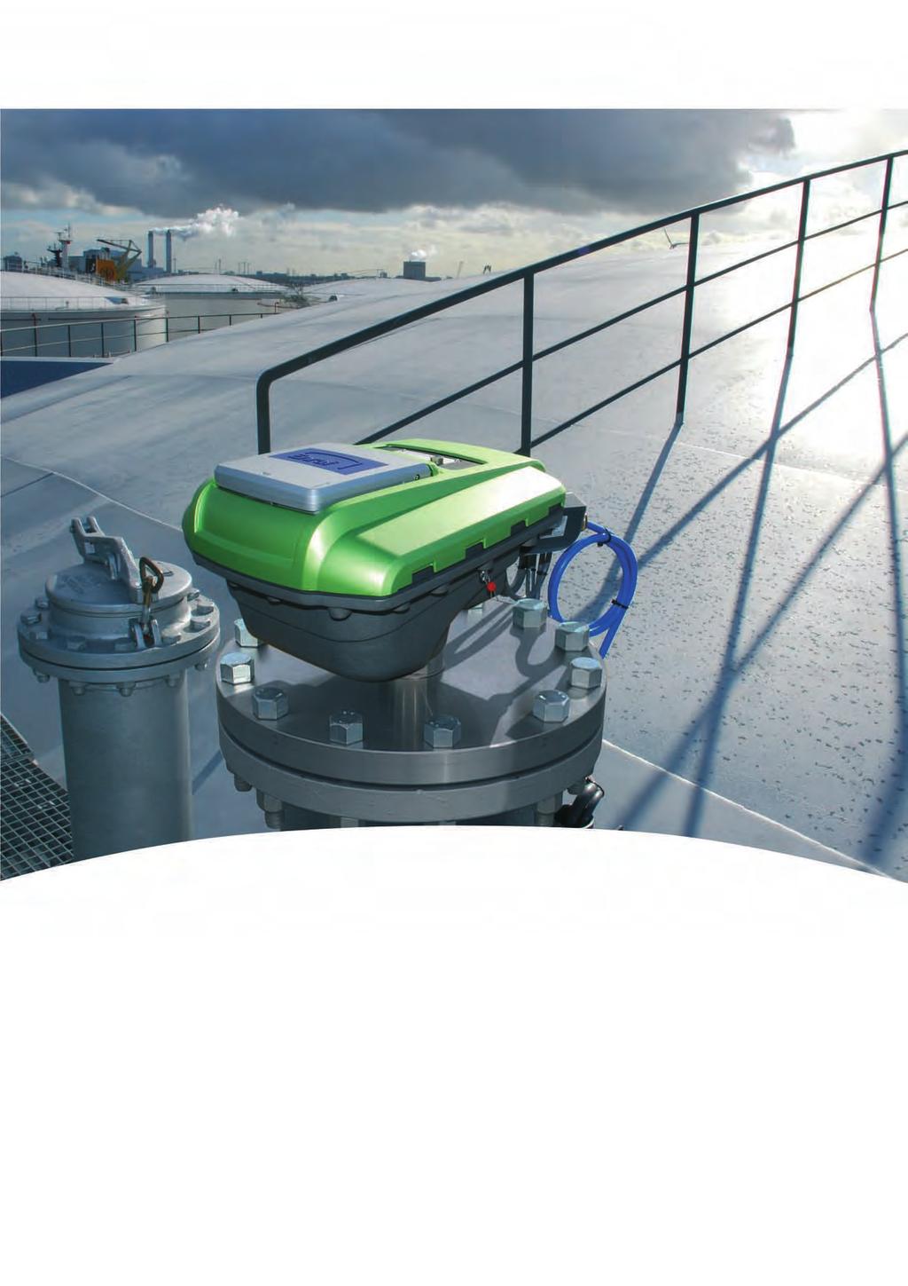
Terminal Automation Solutions SmartRadar FlexLine Global Experience. Locally Applied.
 Terminal Automation Solutions SmartRadar FlexLine Global Experience. Locally Applied. Honeywell Enraf provides an integrated solution to meet all terminal management needs, however large or small. Since
Dräger Polytron 8100 EC Detection of toxic gases and vapors
 Dräger Polytron 8100 EC Detection of toxic gases and vapors The Polytron 8100 EC is Dräger s top of the line explosion proof transmitter for the detection of toxic gases or oxygen It uses a high performance
PME. Series Enclosures. Battery Enclosure (BE) Field Upgrade Installation Instructions. Effective: January, Alpha Technologies
 Field Upgrade Installation Instructions. Effective: January, Alpha Technologies") PME Series Enclosures Battery Enclosure (BE) Field Upgrade Installation Instructions Effective: January, 2004 Alpha Technologies Power Alpha Technologies. Protecting The Power in Communications. Preface
PME Series Enclosures Battery Enclosure (BE) Field Upgrade Installation Instructions Effective: January, 2004 Alpha Technologies Power Alpha Technologies. Protecting The Power in Communications. Preface
Dräger Polytron 8200 CAT Detection of flammable gases and vapors
 Dräger Polytron 8200 CAT Detection of flammable gases and vapors The Dräger Polytron 8200 CAT is an advanced explosion proof transmitter for the detection of flammable gases in the lower explosion limit
Technical Data. Dimensions
 0102 Model Number Features 5 mm flush Usable up to SIL2 acc. to IEC 61508 Accessories EXG-18 Quick mounting bracket with dead stop BF 18 Mounting flange, 18 mm Technical Data specifications Switching element
Dräger Polytron 8100 EC Detection of toxic gases and oxygen
 Dräger Polytron 8100 EC Detection of toxic gases and oxygen The Polytron 8100 EC is Dräger s top of the line explosion-proof transmitter for the detection of toxic gases or oxygen It uses a high performance
Operating Instructions Edition 11/2005. Process monitoring Ex-barrier for Diagnostics Unit SITRANS DA400 7MJ2010-1AA. sitrans
 Operating Instructions Edition 11/2005 Process monitoring Ex-barrier for Diagnostics Unit SITRANS DA400 7MJ2010-1AA sitrans Introduction 1 General safety instructions 2 SITRANS Process monitoring Ex-barrier
TTSIM-1A. TraceTek Sensor Interface Module with Relay. Installation/Operation Instructions. Installation Items (not supplied) Tools Required.
 Tools Required.") TTSIM-1A TraceTek Sensor Interface Module with Relay Installation Items (not supplied) General Information Installation/Operation Instructions Please read these instructions and keep them in a safe place.
TTSIM-1A TraceTek Sensor Interface Module with Relay Installation Items (not supplied) General Information Installation/Operation Instructions Please read these instructions and keep them in a safe place.
Operating Instructions
 Important information: These instructions contain safety information, read and follow them carefully. Dialight will not accept any responsibility for injury, damage or loss which may occur due to incorrect
Original operating instructions Safety switch with guard locking AC901S AC902S
 Original operating instructions Safety switch with guard locking AC901S AC902S 7390914/03 01/2017 Contents 1 Preliminary note...4 1.1 Explanation of symbols...4 2 Safety instructions...4 3 Items supplied...5
Technical Data. General specifications Switching element function Rated operating distance s n 8 mm
 0102 Model Number Features 8 mm non-flush Usable up to SIL 3 acc. to IEC 61508 Application Danger! In safety-related applications the sensor must be operated with a qualified fail safe interface from Pepperl+Fuchs,
Rosemount 2051 Pressure Transmitter with 4-20 ma HART and 1-5 Vdc HART Low Power Protocol
 Quick Installation Guide August 2009 Rosemount 2051 Rosemount 2051 Pressure Transmitter with 4-20 ma HART and 1-5 Vdc HART Low Power Protocol Start Step 1: Mount the Transmitter Step 2: Consider Housing
Instructions. Explosion Proof Smoke Detector U Rev: 9/
 Instructions Explosion Proof Smoke Detector U0. Rev: 9/ 9-7 Table of Contents OVERVIEW... FEATURES... BENEFITS... SPECIFICATIONS... OPERATION... Warm Up... Outputs... Integral Wiring Compartment... LED...
THERMAL BUILDING SOLUTIONS EN-TraceTekTTSIM1A-IM-H /16
 TraceTek TTSIM-1A TraceTek Sensor Interface Module with Relay Installation/OPERATION Instructions Approvals and Certifications TYPE NM General Signaling Equipment 76LJ Only AC versions are UL listed and
Hazardous Area Zirconia Oxygen Systems
 Operating Instructions IM/EXGP-INT_7 Hazardous Area Zirconia Oxygen Systems Interface Electronics Unit ABB The Company We are an established world force in the design and manufacture of instrumentation
KM300 Carbon Monoxide Detection System Installation Manual
 GE Security KM300 Carbon Monoxide Detection System Installation Manual P/N 1068922 REV 2.0 16SEP09 Copyright Copyright 2009 GE Security, Inc. All rights reserved. This document may not be copied in whole
Installation Guide. EXGP Oxygen Analyzer System (ATEX) Interface Electronics Unit
 Interface Electronics Unit") EXGP Oxygen Analyzer System (ATEX) Installation Guide Interface Electronics Unit DO NOT OPEN WHEN ENERGISED OR WHEN AN EXPLOSIVE GAS ABB The Company We are an established world force in the design and
EXGP Oxygen Analyzer System (ATEX) Installation Guide Interface Electronics Unit DO NOT OPEN WHEN ENERGISED OR WHEN AN EXPLOSIVE GAS ABB The Company We are an established world force in the design and
Centurion Guided Radar HAWK CGR SERIES
 Safety Instructions CGR (Cat 3GD) Centurion Guided Radar HAWK CGR SERIES ATEX Category 3GD Intrinsically Safe probe / Flameproof enclosure II 3G Ex ia/d IIC T6 T2 Gc II 3D Ex ia tb IIIC T85 C T255 C Dc
IECEx TEST REPORT IEC Explosive atmospheres Part 0: Equipment General requirements
 ExTR Reference Number...: ExTR Free Reference Number...: 223531 Compiled by + signature (ExTL)...: Reviewed by + signature (ExTL)...: NO/NEM/ExTR12.0018/00 Stig André Norheim Arne Hortman Date of issue...:
HAWK SULTAN SERIES Sma rt Universa l Level Tra nsmitter And Network. Equipment types:
 Safety instructions 0359 HAWK SULTAN SERIES Sma rt Universa l Level Tra nsmitter And Network ATEX Category 1 GD (A0) Equipment types: AWRT series Sultan Remote Transducer AWR series Sultan Remote Electronics
Additional Information. Introduction. Temperature transmitter for all communications protocols. Redundancy thanks to two inputs. Measurement made easy
 ABB MEASUREMENT & ANALYTICS COMMISSIONING INSTRUCTION TTF300 Field-mount temperature transmitter Temperature transmitter for all communications protocols. Redundancy thanks to two inputs. Measurement made
Earth-Rite II PLUS Static Earthing System
 READ MANUAL BEFORE COMMENCING WITH INSTALLATION EN Earth-Rite II PLUS Static Earthing System P1 PLUS - DC Supply Installation & Operating Instructions The safety of any system incorporating the equipment