SECTION POLICY MANUAL
|
|
|
- Erica Shelton
- 6 years ago
- Views:
Transcription


1 Menlo Park Fire Protection District Bureau of Fire Prevention and Life Safety 170 Middlefield Rd. Menlo Park, CA Bureau of Fire Prevention and Life Safety SECTION POLICY MANUAL This manual shall serve as a supplemental instruction and interpretation manual for the Fire Prevention Code. Updated
2 Table of Contents Fire Department Access 3-20 Fire Alarm and Detection Systems Commercial Fire Sprinklers Residential Fire Sprinklers Emergency Radio Communication Piped Air SCBA Refilling System Public Assemblages and Events Water Supply
3 Fire Department Access Information Packet Menlo Park Fire Protection District Bureau of Fire Prevention and Life Safety 3
4 MENLO PARK FIRE PROTECTION DISTRICT GUIDELINE FOR PRIVATE ROADS AND DRIVEWAYS Includes requirements for Gates, Turnarounds & Turnouts SCOPE. This guideline provides the minimum requirements necessary for Driveways of any length with Gates, Driveways exceeding 150 feet in length, and Private Roads of any distance. In addition to the requirements set forth within this guideline, Private Roads or Driveways shall also comply with the 2016 California Fire Code (CFC), Chapter 5 and Appendix D. When necessary, these guidelines may be modified to ensure adequate access for fire apparatus and public safety. Some factors that may contribute to modifications include walls, cliffs along roads or driveways, angle of approach or departure, grade/slope, and the likelihood of future obstructions. DEFINITIONS AASHTO HB-17: American Association of State Highway and Transportation Officials, the 17 th edition Standard for Highway Bridges. ALL WEATHER ROAD: A road or driveway constructed of asphalt, concrete, or other approved driving surface capable of supporting the imposed load of fire apparatus weighing at least 80,000 pounds (34,050 kg). PRIVATE ROAD: An access road that is outside the boundaries of the properties being served and/or serving 3 or more dwelling units. GATES The design for all gates across driveways and private roads shall be approved by the Fire District. Gates shall comply with all of the following criteria: 1. A minimum clear, unobstructed width of not less than 20 feet shall be provided. 2. Gates shall be of the swinging or sliding type. 3. Gates may have electric opening devices, but shall allow manual operation by one person. 4
5 4. Gate components shall be maintained in an operative condition at all times and replaced or repaired when defective. 5. All locking devices shall provide for Fire District access. Electric gates shall have a Knox override key switch installed. Please see Menlo Park Fire District Guideline on Key Box Installations for details on Knox override switches. 6. Manual opening gates shall not be locked with a padlock or chain and padlock unless they are capable of being opened by means of forcible entry tools, a Knox Pad Lock is used, or when a Knox Key Box containing the key(s) to the lock is installed at the gate location. 7. Locking device specifications shall be submitted to the Menlo Park Fire District for approval by the fire code official. DRIVEWAYS For Single Family Residential Only Driveway Specifications. Driveways shall extend to within 150 feet of all portions of the facility and all portions of the exterior walls of the first story of the building. Driveways shall provide a minimum unobstructed width of 16 feet (4877 mm) and a minimum unobstructed height of 13 feet 6 inches (4115 mm). Driveways in excess of 150 feet ( mm) in length shall be provided with turnarounds. Driveways in excess of 500 feet (152,400 mm) in length and less than 20 feet (6096 mm) in width shall be provided with turnouts in addition to turnarounds. Fire Sprinkler Allowance. When the most remote single family residence is provided with automatic fire sprinkler protection and is less than 3600 square feet, the driveway distance may be measured from the edge of the street to the face of the structure. Turnarounds. Driveway turnarounds shall have inside turning radii of not less than 30 feet (9144 mm) and an outside turning radii of not less than 45 feet ( mm). Driveways that connect with a road or roads at more than one point may be considered as having a turnaround if all changes of direction meet the radii requirements for driveway turnarounds. Driveways exceeding 1 mile in length shall be provided with approved turnaround areas at ½ mile intervals. 5
6 Turnouts. Driveway turnouts shall be an all-weather road surface at least 10 feet (3048 mm) wide and 30 feet (9144 mm) long. Driveway turnouts shall be located every 500 feet or at the midpoint if the road is 1,000 feet or less. PRIVATE ROADWAYS Roadway Specifications. Private roadways serving 3 or more residential occupancies shall be all-weather roads with a minimum width of 20 feet (6096 mm) and a clear height of 13 feet 6 inches (4115 mm). Roadways shall be designed to accommodate the weight of fire apparatus and the minimum turning radii of 36 feet for fire apparatus. Dead-end roads in excess of 150 feet ( mm) in length shall be provided with turnarounds as specified by CFC Appendix D, Table D Access roads exceeding 1 mile in length shall be provided with approved turnaround areas at ½ mile intervals. Marking of roads. All road identification signs and supports shall be of noncombustible materials. Signs shall have minimum 4-inch-high (102 mm) reflective letters with 1/2 inch (12.7 mm) stroke on a contrasting 6-inch-high (152 mm) sign. Road identification signage shall be mounted at a height of 7 feet (2134 mm) from the road surface to the bottom of the sign. Marking of Fire Protection Equipment. Fire protection equipment and fire hydrants shall be clearly identified accordance with the Menlo Park Fire District Guideline, Water Supplies and Fire Hydrants. On-site fire hydrants shall not be obstructed. Cul-de-sacs, Curves, and 90 Turns. Cul-de-sacs, curves, and 90 turns shall be in accordance with CFC Appendix D. No obstructions are allowed within the cul-de-sac, such as trees, planters, islands etc. GENERAL REQUIREMENTS Surface. All the items in this standard shall meet the requirements for an all-weather road. Landscape. Landscaping shall not interfere with the required fire apparatus access. Parking. Parking (or any other obstruction) will not be allowed on any of the items in this standard, unless additional space is provided and approved. 6
7 Fire Lane Signs. Installation and placement of signs and markings and designating fire lanes shall be in accordance with Menlo Park Fire Protection District Guideline for Designation and Marking of Fire Lanes. Easements. Access improvements (roads, turnarounds and turnouts) that cross property lines shall be recorded with the San Mateo County Tax Assessors Office. Bridges and elevated surfaces. Where a bridge or an elevated surface is part of the private roadway or driveway, the bridge shall be constructed and maintained in accordance with AASHTO HB-17 and CFC Chapter 5 Section Address markers. All buildings shall have a permanently posted address, which shall be placed at each driveway entrance and be visible from both directions of travel along the road. Permanent addresses on new construction and substantial remodels shall be internally or externally illumined from dusk to dawn. Addresses shall be posted at the beginning of construction and shall be maintained thereafter. The address shall be visible and legible from the road on which the address is located. Address signs along one-way roads shall be visible from both the intended direction of travel and the opposite direction. Where multiple addresses are required at a single driveway, they shall be mounted on a single post, and additional signs shall be posted at locations where driveways divide. Where a roadway provides access solely to a single commercial or industrial business, the address sign shall be placed at the nearest road intersection providing access to that site. Grades. The gradient for private roadways and driveways shall not exceed 10%. Turnarounds and cul-de-sacs shall not have a grade greater than 5% in any direction. Turnouts, curves, and 90 turns shall not have a grade greater than allowed for the road they are on. Transitions between grade changes shall not exceed 5% and shall not interfere with the angle of approach, angle of departure or high centering of fire apparatus. Timing of Installation. Access roadways and water supply, including the items required by this guideline, shall be provided prior to and kept in place during the time of construction. PLAN CHECKS Plan check. Two copies of a clear accurate site plan, with scale shown, are required for plan review. Plans shall include fire hydrant location(s) with the submittal. When 7
8 approved, one copy will be kept by the Bureau of Fire Prevention and Life Safety and Job Copy will be returned to the applicant. Final approval is subject to an onsite inspection. 8
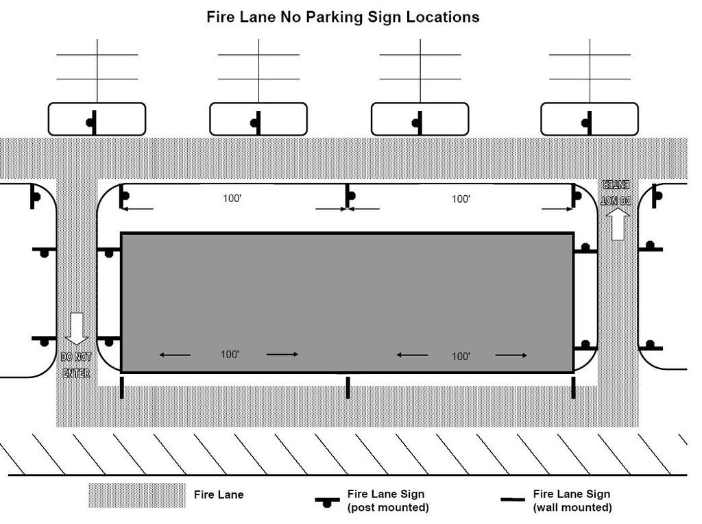
9 MENLO PARK FIRE PROTECTION DISTRICT GUIDELINE FOR DESIGNATION AND MARKING OF FIRE LANES Scope. This guideline provides standard requirements for the installation and placement of signs and markings designating fire lanes when required by the Menlo Park Fire Protection District to provide adequate fire apparatus access. Sign requirements include fire lanes and access roads on both private residential developments and private commercial and industrial properties. Also included in this guideline are requirements for painting curbs and designated areas without curbing. OPTION #1 NO PARKING Signs Sign A Requirements: FIRE LANE SIGNS FIRE LANES AND ACCESS ROADS ON PRIVATE RESIDENTIAL DEVELOPMENTS Signs marking fire lanes are to be spaced so they can be easily read from one sign to another, but in no case shall the signs be more than 100 feet apart. Signs are to face on-coming vehicular traffic. All curbs and adjoining fire lanes or posted areas must be painted red and labeled in white, NO PARKING FIRE LANE. All curbs and signs are to be maintained by the property owner All areas posted under Option #1 are to use sign A All signs must conform to Menlo Park Fire Protection District Guidelines. OPTION #2 ENTRANCE Signs Sign B Requirements: One (1) sign is required at all points of entry to properties with marked parking stalls. Signs are to face on-coming vehicular traffic All curbs adjoining fire lanes or posted areas are required to be painted red and labeled in white, NO PARKING FIRE LANE. 9
10 All curbs and signs are to be maintained by the property owner. All signs must conform to Menlo Park Fire Protection District Guidelines FIRE LANE SIGNS FIRE LANE AND ACCESS ROADS ON PRIVATE COMMERCIAL AND INDUSTRIAL PROPERTY OPTION #1 NO PARKING Signs Sign A Requirements: Signs are required within three (3) feet of each end of curbed area and spaced a maximum of fifty (50) feet apart thereafter. In addition, one (1) sign is required for each island adjacent to a fire lane or access road if the road width is less than 26 feet. Signs are to face on-coming vehicular traffic. All curbs and signs are to be maintained by the property owner. All signs must conform to Menlo Park Fire Protection District Guidelines. OPTION #2 ENTRANCE Signs Sign B Requirements: One (1) sign is required at all points of entry to properties with marked parking stalls. Signs are to face on-coming vehicular traffic All curbs adjoining fire lanes or posted areas are required to be painted red. All curbs and signs are to be maintained by the property owner. All signs must conform to Menlo Park Fire Protection District Guidelines 10
11 Enforcement California Vehicle Code Section Fire lanes; parking violations; and signs: In addition to Section 22500, no person shall stop, park or leave standing any vehicle, whether attended or unattended, except when necessary to avoid conflict with other traffic or in compliance with the directions of a peace officer or official traffic control device along the edge of any highway, at any curb, or in any location in a publicly or privately owned or operated off-street parking facility, designated as a fire lane by the fire department or fire district with jurisdiction over the area in which the place is located. The designation shall be indicated by (1) a sign posted immediately adjacent to, and visible from, the designated place clearly stating in letters not less than one inch in height that the place is a fire lane, (2) by outlining or painting the place in red and, in contrasting color marking the place with the words "FIRE LANE", which are clearly visible from a vehicle or (3) by red curb or red paint on the edge of the roadway upon which is clearly marked the words "FIRE LANE". 11
12 12
13 Fire Lane Post Installation (12' x 18') A. Height of the sign: 7' in sidewalk or pedestrian areas, 5' in all other areas. B. Distance from front of curb: 18" with standard curb, 24" with rolled curb, to center of post. C. Depth of sign base: 24" minimum embedment. NOTE: Signs may be mounted to an existing post or on a building that is no more than 24" from curb or edge of road surface. 13
14 14
15 15

16 TOWING OF VEHICLES FROM FIRE LANES ON PRIVATE PROPERTY BY THE PROPERTY OWNER The owner of a private property containing a fire lane may have a vehicle towed from a fire lane on their property. The owner of the property usually contracts with a private towing company in advance. The following are the requirements for a property owner to tow a vehicle from a fire lane on his/her property. 1. Signs must be in place before an owner may tow. The signs must be displayed in plain view at all entrances to the property. The sign must be not less than 12x18 inches in size. Lettering must not be less than one inch in height. Signs must clearly state that stopping in a fire lane is prohibited. The sign must indicate that vehicles will be removed at the owner s expense. The sign must contain the telephone number of the local traffic law enforcement agency. The sign must contain the name and telephone number of each towing company that is party to a written agreement with the property owner. 2. The California Vehicle Code, Section 22658, requires the owner of the property to notify the local traffic law enforcement agency within one hour of towing. 3. Fire lanes shall be marked according to California Vehicle Code Section , as indicated above. 4. Owners of private property may post NO PARKING signs for various reasons other than a fire lane and have vehicles removed. Refer to the California Vehicle Code, Section
17 MENLO PARK FIRE PROTECTION DISTRICT GUIDELINE FOR THE INSTALLATION OF TRAFFIC CALMING DEVICES Scope. When allowed by the fire code official, the installation of any traffic calming device shall be in accordance with Federal, State, and County guidelines and the requirements set forth in this Standard. Traffic Calming Devices Plans for traffic calming devices must be submitted for the Department's review and approval. We support the design of safe streets and the need for devices intended to slow traffic, i.e., islands, roundabouts, and bump outs; however, we discourage the use of speed humps. In most cases, traffic calming devices can be designed within our minimum requirements. Emergency Response Issues with speed humps: Concern over jarring of emergency rescue vehicles Approximate delay of between 3 and 5 seconds per hump for fire trucks and up to 10 seconds for ambulances with patients Locations. Traffic calming devices shall not be allowed on designated fire apparatus primary response routes, see for current Primary Response Route map. When approved by the fire code official, traffic calming devices shall be installed in accordance with the following Federal Highway Administration guidelines: 1. Traffic calming devices may only be installed on residential streets. They shall not be used on major roads, bus routes, or primary emergency response routes. 2. Speed humps shall not be placed mid-block or at intersections. 3. Traffic calming devices shall not be located on grades greater than 8 percent. 4. The maximum height of a speed hump shall not exceed 3.5 inches. 5. In accordance with San Mateo County Policy, speed humps shall not be placed on streets where posted speed limits are 30 miles per hour or more. Installation of traffic calming devices. When allowed by the fire code official, traffic calming devices such as roundabouts or other devices that are meant to disrupt the 17
18 normal flow of traffic, such devices shall be installed in a manner that does not obstruct the required width of a fire lane as specified by Section of the California Fire Code and Installation of speed humps. When approved by the fire code official, speed humps may be installed in accordance with the Federal Highway Administration Manual on Uniform Traffic Control Devices or the San Mateo County Department of Public Works traffic humps drawing. 18
19 19
20 20
21 Fire Alarm and Detection Systems Information Packet Menlo Park Fire Protection District Bureau of Fire Prevention and Life Safety MENLO PARK FIRE PROTECTION DISTRICT GUIDELINE FOR THE INSTALLATION OF FIRE ALARM AND DETECTION SYSTEMS 21
22 SCOPE: This guideline applies to the design and installation of automatic fire alarm systems in all buildings and structures except one and two-family dwellings, manufactured homes, and public schools. This guideline is to be used in conjunction with the latest State Fire Marshal adopted version of NFPA 72, the 2016 California Fire Code, the Menlo Park Fire Protection District Ordinance, and other applicable national standards including manufacturer recommendations. 1. SYSTEM DESIGN AND INSTALLATION All individuals and companies who intend to engage in the installation or alteration of fire alarm or monitoring systems are subject to the requirements of this standard. Plans for a fire alarm or monitoring system are required to be designed by a Registered Professional Engineer (Electrical, Mechanical, or Fire Protection), licensed by the State of California, Board of Professional Engineers. All copies of the plans shall be stamped and signed by the licensed individuals. A C-10 Licensed Contractor shall only design systems that the firm has a contract to install. The fire alarm or monitoring system needs to be installed by an individual who holds a State of California C-10 Contractor s License. 2. GENERAL REQUIREMENTS A. In accordance with Menlo Park Fire District Ordinance, Section 907.7, fire alarms systems in new commercial structures shall obtain a UL Certificate for the system prior to final inspection. B. All systems shall be fully addressable to Central Station. C. The Remote annunciator shall be located at the main entrance to the building, or other location approved by the fire code official. D. A durable map shall be provided at the Remote Annunciator indicating the location of the Fire Alarm Control Panel and all Fire service features. E. The instructions to silence and reset the Fire Alarm shall be located at the Fire Alarm Control Panel. 3. PLAN SUBMITTAL PROCEDURE 22
23 Menlo Park Fire District requires a Fire District Plan Check Application accompanied by a minimum of two sets of plans, State Fire Marshal equipment lists, battery calculation sheet, and the appropriate fees (See Menlo Park Fire District Fee Schedule). All fees shall be paid at the time of plan submittal. Plans will be checked and when approved, will be stamped, signed and dated. The Fire District will retain one set of the plans. One copy of the Fire District stamped plans and the original Fire District Permit Card shall be maintained on the job site. Modifications/changes to existing plan may require an additional plan check by the Fire District. Excessive field changes will require re-submittal of plans along with additional plan check fees. 4. PLAN SUBMITTAL INFORMATION I. Title or Cover sheet shall include: A. Address of alarm installation B. Phone number of alarm installation location C. Contact person at alarm installation location D. Occupancy classification of the building or area E. Whether or not the building is sprinklered F. Name, address and phone number for person designing the system G. What codes or standards the system is designed to (i.e., NFPA 72) H. Name, address and phone number and license number of the installing contractor. II. Equipment List to include: A. Manufacturer s name and model number for each device B. Quantities of each type of device C. Description of each device (i.e., heat detector, ionization detector, duct detector, control unit, etc.) D. California State Fire Marshal s listing number and listing sheet with renewal number. E. Mounting requirements (wall, ceiling, flush, etc.) F. Symbols to be used on drawings, along with legend G. Manufacturer s cut sheet should be included III. Drawings: A. Drawings and attachments should be clearly labeled and legible B. Stick on dots or similar materials are not acceptable C. Submit at least two copies of all drawings and attachments. D. Contact the Building Department regarding any additional permits required E. All drawings must be to scale, and scale clearly indicated. Floor plans are required to show: 1. Device(s) location 2. Type of device(s) 3. Control(s) location 4. Conduit connection and size 23
24 a. Surface mounted installation b. Semi-flush mounted installation c. Flush mounted installation 5. Type and size of wire or cable 6. Exterior mounted device, Weatherproof Point to Point system wiring diagram showing: 1. Interconnection of identified devices and controls 2. Type of power feed to the control panel 3. External connection of modules in control panel Alarm Circuit load consumption of furthest alarm circuits on drawing showing: 1. Quantity of bells on furthest circuit and current consumption 2. Length of furthest circuit and resistance of wire Fire Alarm System Riser Diagram IV. Attachment to Drawings: Battery calculation sheet showing: 1. Standby power consumption of all current drawing devices times the required by minimum requirements of NFPA a. Power consumption of control panel modules b. Power consumption of all devices on standby, including door holder, relays, etc. 2. Alarm power consumption of all current drawing devices, multiply the minutes required by minimum requirements of NFPA a. Add power consumption of all operating signals, lights, relays, etc. b. Omit power consumption of door holders, etc. c. Formula format for battery calculation. Sequence of operating instructions: 1. Step by step instruction for the operation of each type of initiating device in the system including reset. Sequence of test inspection operating instructions: 1. Identify monitoring company 2. Identify what auxiliary function switches or devices are to be disconnected before testing is to be started. 3. Selection of operation of at least one type of device in each initiating circuit as outlined in Sequence of Operation. 4. What functions are to take place upon operation of selected device. 5. Identification of equipment supplier and installer. State Fire Marshal s listing sheets for each device or component 5. INSPECTION AND TESTING PROCEDURE 24
25 A. The fire alarm system and all new fire alarm components shall be tested in accordance with NFPA 72. B. A sheet shall be provided to the Fire Inspector indicating that a 100% pretest through the Central Station has occurred, and that the fire alarm system functions correctly and passed the pretest. C. A copy of the Record of Completion and Fire Alarm Certificate shall be presented to the Fire Inspector. D. The building may not be occupied prior to testing of the fire alarm system by the Bureau of Fire Prevention and Life Safety. 6. SCHEDULING INSPECTIONS A. The inspection fee that is paid at the time of plan submittal will provide for one field inspection to complete the project. For projects requiring additional inspections, requests will not be accepted unless additional fees are paid prior to scheduling an inspection. B. It is the responsibility of the installing contractor/owner to be on the job site during the inspection with original approved plans and the original permit card. Failure to do so will result in the cancellation of the inspection. Cancelled inspections will be counted as one inspection. C. Inspection requests can only be taken from the installing contractor. D. Contact Fire District Inspectors at least two business days prior for scheduling an inspection. Call the inspector of record indicated on the permit card. E. Inspection times are approximate and may vary because of delays at previous inspections or emergency response by Fire District personnel. Please allow time on either side of the inspection time for the inspector to arrive. Commercial Fire Sprinkler 25
26 Information Packet Menlo Park Fire Protection District Bureau of Fire and Life Safety MENLO PARK FIRE PROTECTION DISTRICT GUIDELINE FOR THE INSTALLATION OF FIRE SPRINKLER SYSTEMS 26
27 SCOPE: This guideline applies to the design and installation of automatic fire sprinkler systems in all buildings and structures except one and two-family dwellings and manufactured homes. This guideline is intended to be used in conjunction with the latest State Fire Marshal adopted version of NFPA 13, the 2016 California Fire Code, the 2016 California Building Code, the Menlo Park Fire Protection District Ordinance, and other applicable national standards including manufacturer recommendations. 1. SYSTEM DESIGN AND INSTALLATION All individuals and companies who intend to engage in the installation or alteration of fire sprinkler systems are subject to the requirements of this standard. Plans for a fire sprinkler system shall be designed by a State of California C-16 Licensed Contractor or by a Registered Professional Engineer (Civil, Mechanical, or Fire Protection), licensed by the State of California, Board of Professional Engineers. All copies of the plans shall be stamped and signed by the licensed individuals. A C-16 Licensed Contractor shall only design systems that the firm has a contract to install. The fire sprinkler system shall be installed by an individual who holds a State of California C-16 Contractor s License. 2. GENERAL REQUIREMENTS A. When alterations of the existing light hazard sprinkler system exceed 50% of the compartmented area, the existing fire sprinklers shall use quick response sprinklers, if the sprinklers are spaced at light hazard in accordance with NFPA 13. B. Sprinkler system water flow alarm and valve tamper switches are required to be supervised by an approved central station for systems with more than 20 sprinklers. Shell buildings and tenant areas will not receive a final inspection until the sprinkler alarm supervision is complete and in service. C. An exterior door is required to provide direct access to an interior fire sprinkler riser. D. When any building or structure or portion thereof undergoes an alteration, the portion of the fire sprinkler system in the alteration shall be upgraded to current codes and standards. This shall include but not be limited to the upgrading of seismic joints, sway bracing, fasteners and hangers. E. CPVC Piping shall not be allowed for any NFPA 13 fire sprinkler system. 27
28 Exception: When approved by the Fire Code Official, CPVC piping may be used in a NFPA 13 fire sprinkler system for residential portions of occupancies. F. Sprinklers shall be installed at stair landings for multi-story buildings. G. Sprinklers shall be provided in all areas including combustible or noncombustible concealed spaces, 6 inches or more. Exceptions: Combustible or noncombustible concealed spaces if the building owner and the fire code official agree in writing that combustible or noncombustible concealed spaces, 6 inch or less are unlikely to change in the future. 3. WATER SUPPLIES AND HYDRAULIC CALCULATIONS A. For single story buildings or structures with an interior height of up to 18 feet as measured from the finished floor to the underside of ceiling, the minimum sprinkler design shall be 0.18 gpm over the most remote 3,000 sq. ft. area plus 500 gpm hose stream included at the base of the riser. For buildings or structures with an interior height of over 18 feet from finished floor to the underside of the ceiling, the minimum sprinkler design shall be 0.33 gpm over the most remote 3,000 sq. ft. area plus 500 gpm for hose streams included at the base of the riser. With written approval from the fire code official, schools, churches and similar occupancies which have few hazards and are unlikely to change may use lesser sprinkler design densities allowed by NFPA 13 and Chapter 9 of the Fire Code. B. Sprinkler design shall be adequate for all anticipated high hazard situations such as high piled combustible storage, plastic storage 6 ft. or higher, flammable liquids and other special hazards. C. The original sprinkler design for the building shall be maintained during all tenant improvements and other changes. One sprinkler may be added per plugged outlet included in the original sprinkler calculations. All other additional sprinklers are to be added from cross mains and feed mains unless the system is recalculated to verify that the additional sprinklers are acceptable. D. NFPA 13 Section , Room Design Method, shall be omitted. The design for any existing light hazard sprinklered occupancy shall be not less than 0.1gpm over the most remote 1,500 sq. ft. area. E. The following information shall be contained in the hydraulic calculations. a. Calculations must conform to manufacturer s specifications. 28
29 b. K factors for all sprinklers. c. C values for the type of pipe used. d. A pump curve or city supply curve, where the total demand point is clearly plotted. e. A 10% reduction in the available water pressure shall be included in all calculations F. When water storage tanks are required, each tank shall have a connection to a supply source to refill the tank automatically. 4. SYSTEM COMPONENTS A. In addition to system components required by NFPA 13, all systems shall also include the following: 1. An approved rubber faced check valve located on the on the riser. 2. All valves shall have an all-weather sign affixed to them, which indicates their purpose. The Fire Department Connection (FDC) shall be posted with the address of the building it services. 3. In addition to the requirements of California Fire Code Section , floor control valves shall be provided for each floor of any building or structure two or more stories in height. 4. Check valves shall be provided on each floor of any building or structures. 5. PLAN SUBMITTAL PROCEDURE Menlo Park Fire District requires a Fire District Plan Check Application accompanied by two sets of plans, hydraulic calculations, a current fire flow test report, and the appropriate fees (See Menlo Park Fire District Fee Schedule). All fees shall be paid at the time of plan submittal. Plans will be checked and if approved, will be stamped, signed and dated. The Fire District will retain one set. One copy of the Fire District original stamped plans and the original Fire District Permit Card shall be maintained on the job site. Modifications/changes to existing plan will require an additional plan check by the Fire District. Excessive field changes may require re-submittal of plans along with additional plan check fees. 6. PLAN SUBMITTAL INFORMATION 29
30 A. Sprinkler plans and calculations shall be submitted with all the information required by the latest approved edition of NFPA 13, INCLUDING ALL DETAILS FOR HANGERS, and EARTHQUAKE SWAY BRACING AND FASTENERS. The sprinkler system will not receive a final inspection unless and until the installation is in accordance with the approved plans, and the placard with the design information has been provided on the riser. NFPA , CFC B. To speed up the plan check process and to avoid the possibility of returning the plans for corrections, please use the following checklist, prior to submittal, to insure that the appropriate information is included on the working sprinkler drawings: 1. Name of owner and/or occupant 2. Location of project, including street, number, and city. 3. Name of sprinkler installer, address, phone number, type of license and license number. 4. Total number of square feet. 5. Point of compass. 6. All plans must be to scale or dimension. The scale shall be no smaller than 1/8 inch=1 foot. 7. Plot plan showing tank, pump, structures, underground pipe size and type, point of supply connections, depth of bury, type and size of any valves or meters. 8. Piping plan showing tank, pump, and structure elevations as they relate to each other. 9. Full height cross-section showing building construction types, vaulted, and beamed ceiling locations. 10. Water tank details including size and type of construction (Where applicable). 11. Detailed hydraulic calculations (See item 3 above). 12. Sprinkler head spacing. 13. Show clearly all unsprinklered areas. 14. Indicate manufacturer, style, model, orifice size, and K factor of each sprinkler used. 15. Indicate the type and size of pipe. 16. Provide hanger details. 30
31 17. Indicate type of fitting used. 18. Use of each room. 19. Location of heat sources. 20. Water flow information including: Flow location Static pressure, psi Residual pressure, psi Flow, gpm Date Time Test conducted by or information supplied by. C. The following notes shall be completed and placed verbatim on the working sprinkler plans: 1. This fire sprinkler system shall be designed and installed in accordance with NFPA 13 and Menlo Park Fire District Standards. 2. Only listed and approved devices shall be installed in this system. 3. Only new, listed sprinklers shall be employed in the installation of this sprinkler system. 5. All piping shall be provided with hangers and shall be supported per code and manufacturer s specifications. 6. All piping shall be hung from structural members. 7. Underground mains and lead-in connections shall be flushed before connection is made to sprinkler piping. The flush shall take place in the presence of Fire District Inspectors. See also Section 7-E below. 8. This fire sprinkler system shall be tested and inspected at both rough and final inspections, prior to occupancy being granted. Call two working days in advance to schedule all inspections. 7. INSPECTION AND TESTING PROCEDURE A. Welded piping connections shall be inspected before installation. B. The sprinkler system shall be field tested and inspected at the rough plumbing stage (i.e. exposed pipe and fitting stage) by the Fire Prevention Division. All new systems shall be hydrostatically tested (not pneumatic) for leakage at 200psi. For existing systems, when 20 sprinkler heads or more are added, a hydrostatic test of 50psi over normal water pressure shall be required. C. Riser detail showing system split, pressure gauge, check valve, main control valve, relief valve (where applicable), main drain valve. D. Indicate the manufacturer, model, type, and pump curve of the booster pump (where applicable). 31
32 E. All systems shall have an underground flush completed at time of hydrostatic test prior to connecting the underground to the overhead piping. F. The sprinkler system and all of the related components shall be tested and inspected by the Fire Prevention Division at the final inspection stage, prior to occupancy being granted. G. At least two spare sprinklers of each type, temperature rating, and orifice size used in the system and a sprinkler wrench shall be provided and located at the system riser. H. A 5 Year Service Test sticker shall be placed on the riser at the time the sprinkler system is put in service or at the time of final inspection if the system is put in service before final inspection. 8. SCHEDULING INSPECTIONS A. The inspection fee that is paid at the time of plan submittal will provide three inspections to complete the project (one weld inspection, one rough-in, and one final inspection). For projects that exceed this limit, inspection requests will not be accepted unless additional fees are paid prior to scheduling an inspection. B. It is the responsibility of the installing contractor/owner to be on the job site during the inspection with original approved plans and the original permit card. Failure to do so will result in the cancellation of the inspection. Cancelled inspections will be counted as one inspection. C. Inspection requests can only be taken from the installing contractor. D. Contact Fire District Inspectors at least two business days prior to inspection for scheduling an inspection. Call the inspector of record indicated on the permit card. E. Inspection times are approximate and may vary because of delays at previous inspections or emergency response by Fire District personnel. Please allow time on either side of the inspection time for the inspector to arrive. Residential Fire Sprinkler Information Packet 32
33 Menlo Park Fire Protection District Bureau of Fire Prevention and Life Safety MENLO PARK FIRE PROTECTION DISTRICT GUIDELINE FOR INSTALLATION OF RESIDENTIAL FIRE SPRINKLERS SCOPE: This guideline applies to the design and installation of automatic fire sprinkler systems in one and two-family dwellings and manufactured homes. This guideline is meant to be used in conjunction with NFPA 13D, Installation of Sprinkler Systems in One and Two-Family Dwellings 33
34 and Manufactured Homes, the California Fire Code, the California Building Code, the California Residential Code, the Menlo Park Fire Protection District Ordinance, and other applicable national standings including manufacturer recommendation. 1. SYSTEM DESIGN AND INSTALLER REQUIREMENTS All individuals and companies who intend to engage in the installation or alteration of fire sprinkler systems in one and two family dwelling are subject to these requirements. Plans for a fire sprinkler system shall be designed by a State of California C-16 Licensed Contractor or by a Registered Professional Engineer (Civil, Mechanical, or Fire Protection), licensed by the State of California, Board of Professional Engineers. All copies of the plans shall be stamped and signed by the licensed professionals. A C-16 Licensed Contractor shall only design systems that the firm has a contract to install. The fire sprinkler system shall be installed by an individual who holds a State of California C-16 Contractor s License or, by an owner-builder provided the individual owns the dwelling. 2. PLAN SUBMITTAL Procedure Menlo Park Fire District requires a Fire District Plan Check Application accompanied by two sets of plans, hydraulic calculations, and the appropriate fees (See Menlo Park Fire District Fee Schedule). All fees shall be paid at the time of plan submittal. Plans will be checked and if approved, will be stamped, signed and dated by Fire District officials. The Fire District will retain one set of plans. One copy of the original approved plans and the original Fire District Permit Card shall be maintained on the job site. Modifications and changes to the existing plan will require an additional plan check by Menlo Park Fire District along with additional plan check fees. Plan Submittal Information Systems shall be designed and calculated in accordance with NFPA 13-D Chapter 8 Systems Design. 1. To speed up the plan check process and to avoid the possibility of returning the plans for corrections, please use the following checklist, prior to submittal, to insure that the appropriate information is included on the working sprinkler drawings: 34
35 a. Name of owner and/or occupant b. Location of project, including street, number, and city. c. Name of sprinkler installer, address, phone number, type of license and license number. d. Total number of square feet. e. Point of compass. f. All plans must be to scale or dimension. The scale shall be no smaller than 1/8 inch=1 foot. g. Plot plan showing tank, pump, structures, underground pipe size and type, point of supply connections, depth of bury, type and size of any valves or meters. h. Piping plan showing tank, pump, and structure elevations as they relate to each other. i. Full height cross-section showing building construction types, vaulted, and beamed ceiling locations. j. Water tank details including size and type of construction (where applicable). k. Detailed hydraulic calculations (See item 2 below). l. Sprinkler head spacing. m. Show clearly all unsprinklered areas. n. Indicate manufacturer, style, model, orifice size, and K factor of each sprinkler used. o. Indicate the type and size of pipe. p. Hanger details. q. Indicate type of fitting used. r. Use of each room. s. Location of heat sources. t. Local water purveyor requirements and approval of design if required u. Water flow information including: Flow location Static pressure, psi Residual pressure, psi Flow, gpm Date Time Test conducted by or information supplied by. 2. The following information shall be contained in the hydraulic calculations. a. Calculations must conform to manufacturer s specifications. b. K factors for all sprinklers. c. C values for the type of pipe used. d. A pump curve or city supply curve, where the total demand point is clearly plotted. e. A 10% reduction in the available water pressure shall be included in all calculations. f. Provide a 5 gpm domestic demand at the base of the riser in the calculations. 35
36 3. WATER SUPPLY Design Calculations Automatic fire sprinkler protection shall be designed as follows: Square footage of structure Design Calculation Less than 3600 sq. ft. 2 Head Calculation 3600 sq. ft. or larger 4 Head Calculation Automatic Booster Pump 1. When the domestic water supply is deficient or a water tank is being used to supply the automatic sprinkler system, an automatic booster pump may be required to maintain the required pressure at the minimum gallons per minute. 2. The pump must be automatically activated upon system demand. 3. The pump must be of self-priming type. 4. The pump shall be installed on the main water line prior to the domestic and fire split. 5. A bypass shall be designed and installed around the pump to ensure street pressure is maintained in event of pump failure. Water Storage Tanks 1. When a water storage tank is required, the tank(s) shall have a connection to a supply source to refill the tank automatically. 4. GENERAL REQUIREMENTS Automatic sprinkler systems installed in one and two-family dwellings shall be installed throughout the dwelling in accordance with NFPA 13D. Additional requirements for NFPA 13D sprinkler systems shall include: 1. Automatic fire sprinkler protection shall extend to attached garages and basements. Fire sprinkler protection may extend to accessory structures within 20 feet of the main structure 36
37 and may also be required to extend to other structures that are located further than 150 feet from fire apparatus access. See CFC Section Pilot sprinkler heads shall be installed in attic spaces that are more than 30 inches in depth. Pilot sprinklers shall be placed every 30 feet on center. 3. Automatic fire sprinklers shall be included in all bathrooms. 4. Automatic fire sprinklers shall be provided under stairways unless enclosed and filled with insulation. 5. The main drain shall be a minimum ½ inch. 6. The main control valve shall be of indicating type and located above grade. 7. The exterior fire bell shall be placed in the same area as the water supply control valve or per fire inspector requirements. 8. Only listed and approved devices shall be installed in this system. 9. All piping shall be provided with hangers and shall be supported per code and manufacturer s specifications. All piping shall be hung from structural members. 10. Underground mains and lead in connections shall be installed in accordance with requirements of the California Plumbing Code. 11. Where system piping or pumps are located in areas subject to freezing, steps shall be taken to protect system integrity; this may include, but is not limited to, heating and/or installation of insulation. 12. All sprinkler systems shall have a single supply main serving both the automatic sprinkler system and the domestic system. See Diagram Requirements of the local water purveyor shall be followed and included on plans for submittal. 15. No wires shall be allowed to touch fire sprinkler piping due to pipe degradation. 16. Passive purge, backflow prevention and reduced pressure devices shall be approved by the local water purveyor for your system design. 5. SYSTEM COMPONENTS 1. An approved rubber faced check valve shall be located on the system side of the main control valve. 2. All valves shall have an all-weather sign affixed to them, which indicate their purpose. 37
38 3. For systems with normal operating pressure in excess of 100 psi, a listed pressure relief valve shall be installed on the riser. Sprinklers 1. Only new listed residential fire sprinklers shall be used. Pressure Gauge 1. A listed pressure gauge shall be installed and maintained on the sprinkler system riser. The pressure gauge shall be installed on the system side of the check valve. Piping 1. Approved plastic pipe may be used when installed in accordance with the manufacturers listing where installed in attics. Adequate insulation shall be provided on the attic side of the piping to avoid exposure of the piping to temperatures in excess of its rated temperature. 2. Insulation, include spray application insulation mixtures, shall be compatible with piping materials in accordance with manufactures specifications. 3. CPVC Piping: CPVC Sprinkler sprig ups in attic space or where CPVC piping is exposed to the temperatures below 40 degrees F, or above 120 degrees F shall require the pipe to be protected against freezing by insulating coverings, frost proof casings, listed heat tracing systems, or other reliable means capable of maintaining minimum temperatures so listed within. a. Method of insulating CPVC piping vertical piping to sprig ups or change in elevation in attic space shall be inspected at time of Rough Inspection. MPFD permits insulation wrap properly sized for vertical section of piping in attic or exterior pipe. b. Installation criteria for installing insulation in unheated attic areas to follow the guidelines of the insulation manufacturer. Per NFPA 13D Section & Figures 9.1.1(a) through 9.1.1(e), and/or Exhibit (note; method of piping anchoring will impact insulation cover). c. CPVC piping shall be installed by persons who have been certified by the manufacturer for installation of CPVC piping. d. Primers and glues shall be listed and approved for use with CPVC piping in systems using CPVC pipe. System Activation 38
39 1. Upon activation of the fire sprinkler system, an interior alarm shall be provided capable of being heard in all sleeping rooms. Smoke alarms shall not act as an interior sounder for water flow unless the smoke alarm is listed and approved for such application. 2. The exterior fire bell shall be placed in the same area as the water supply control valve. 6. MANUFACTURED HOMES AND MULTI-UNIT MANUFACTURED HOUSING WITH TWO DWELLING UNITS A. The Department of Housing and Community Development is responsible for plan approval, in-plant inspection, testing and installation of fire sprinkler systems installed in new manufactured housing units and multi-unit manufactured housing with two dwelling units for sale in California. Prior to shipment of a home containing a fire sprinkler system, the factory is required to affix a Fire Sprinkler System Information and Installer Certification label inside the unit that provides detailed information for the on-site installer and homeowner use. The label is required to be affixed on an inside wall or door of the water heater compartment. B. The installation of a fire sprinkler system in an existing manufactured home or multi-unit manufactured home with two dwelling units requires prior design approval from the Department of Housing and Community Development and inspection approval of the installation prior to the installer covering the piping material with finished wall or ceiling materials. Only the occupant homeowner or a fire protection contractor holding a valid C-16 license may install a fire sprinkler system in an existing manufactured home or multi-unit manufactured home with two dwelling units. Menlo Park Fire Protection District is responsible for plan check, and the General Requirements noted above in Section TESTING PROCEDURE 1. The sprinkler system shall be field tested and inspected at the rough plumbing stage (i.e. exposed pipe and fitting stage) by the Bureau of Fire Prevention and Life Safety. All systems shall be hydrostatically tested (not pneumatic) for leakage for not less than a two hour time period at 200 psi.. 2. The riser shall show the system split (domestic and fire sprinkler piping), pressure gage, check valve, main control valve, relief valve (where applicable), main drain, and domestic shutoff valve. 3. The sprinkler system and all of the related components shall be tested and inspected by the Bureau of Fire Prevention and Life Safety at the final inspection stage, prior to occupancy being granted. 39
40 8. SCHEDULING INSPECTIONS 1. The inspection fee that is paid at the time of plan submittal will provide you with two inspections to complete the project (one rough-in to verify piping installation and ability to hold water pressure and one final inspection when the home is ready for occupancy). For projects that exceed this limit, inspection requests will not be accepted unless additional fees are paid prior to scheduling an inspection. 2. It is the responsibility of the installing contractor/owner to be on the job site during the inspection with approved plans and the original permit card. Failure to do so will result in the cancellation of the inspection. Cancelled inspections will be counted as one inspection. 3. Inspection requests can only be taken from the installing contractor/owner. 4. When scheduling an inspection, please contact Fire District Inspectors at least two business days in advance. Call the inspector of record indicated on the Permit Card. 5. Inspection times are approximate and may vary because of delays at previous inspections or emergency response by Fire District personnel. Please allow one hour on either side of the inspection for the inspector to arrive. Diagram 1: 40
41 41
42 Emergency Radio Communication Information Packet Menlo Park Fire Protection District Bureau of Fire and Life Safety EMERGENCY RESPONDER RADIO SYSTEM FREQUENCY REQUIREMENTS 42
43 Display RX FREQ RX CTCSS TX FREQ TX CTCSS NOTES FIRE CONTROL 1A South Dispatch COMMAND South Command TAC South Tactical TAC South Tactical TAC South Tactical COMMAND County Command VFIRE Stand by TAC Repeated Channels Easter Cross Site N W POLICE Atherton PD Police Dispatch East Palo Alto PD Police Dispatch Menlo Park PD Police Dispatch ALL PD TAC Police Secondary TAC Police Tactical Green/CWMA County Wide Mutual Aid SHERIFF/EMS TRUNKED SYSTEM 700 MHz system range 400 County Center To Downlink base To portable To Uplink Portable To base N W *On the Fire VHF system, listed the simplex channels so that they can be set up as uplink only. We require all the repeated frequencies to be in the BDA system. The simplex frequencies need only uplink preferred, but not required. 43
44 MENLO PARK FIRE PROTECTION DISTRICT STANDARD Emergency Responder Radio Signal Amplification Systems The Menlo Park Fire District follows the current edition of the CA Fire Code Section 510 for adherence for the permit issuance, installation, acceptance and maintenance of Emergency Responder Radio Coverage. CFC SECTION 510 EMERGENCY RESPONDER RADIO COVERAGE Emergency responder radio coverage in new buildings. All new buildings shall have approved radio coverage for emergency responders within the building based upon the existing coverage levels of the public safety communication systems of the jurisdiction at the exterior of the building. This section shall not require improvement of the existing public safety communication systems. Exceptions: 1. Where approved by the building official and the fire code official, a wired communication system in accordance with Section shall be permitted to be installed or maintained in lieu of an approved radio coverage system. 2. Where it is determined by the fire code official that the radio coverage system is not needed. 3. In facilities where emergency responder radio coverage is required and such systems, components or equipment required could have a negative impact on the normal operations of that facility, the fire code official shall have the authority to accept an automatically activated emergency responder radio coverage system Emergency responder radio coverage in existing buildings. Existing buildings shall be provided with approved radio coverage for emergency responders as required in Chapter Permit required. A construction permit for the installation of or modification to emergency responder radio coverage systems and related equipment is required as specified in Section Maintenance performed in accordance with this code is not considered a modification and does not require a permit Technical requirements. Systems, components, and equipment required to provide emergency responder radio coverage system shall comply with Sections through Radio signal strength. The building shall be considered to have acceptable emergency responder radio coverage when signal strength measurements in 95 percent of all areas on each floor of the building meet the signal strength requirements in Sections and Minimum signal strength into the building. A minimum signal strength of -95 dbm shall be receivable within the building Minimum signal strength out of the building. A minimum signal strength of -95 dbm shall be received by the agency's radio system when transmitted from within the building System design. The emergency responder radio coverage system shall be designed in accordance with Sections through Amplification systems allowed. Buildings and structures which cannot support the required level of radio coverage shall be equipped with a radiating cable 44
45 system, a distributed antenna system with Federal Communications Commission (FCC)-certified signal boosters, or other system approved by the fire code official in order to achieve the required adequate radio coverage Technical criteria. The fire code official shall maintain a document providing the specific technical information and requirements for the emergency responder radio coverage system. This document shall contain, but not be limited to, the various frequencies required, the location of radio sites, effective radiated power of radio sites, and other supporting technical information Secondary power. Emergency responder radio coverage systems shall be provided with an approved secondary source of power. The secondary power supply shall be capable of operating the emergency responder radio coverage system for a period of at least 24 hours. When primary power is lost, the power supply to the emergency responder radio coverage system shall automatically transfer to the secondary power supply Signal booster requirements. If used, signal boosters shall meet the following requirements: 1. All signal booster components shall be contained in a National Electrical Manufacturer's Association (NEMA) 4-type waterproof cabinet. 2. Battery systems used for the emergency power source shall be contained in a NEMA 4-type waterproof cabinet. 3. The signal booster system and battery system shall be electrically supervised and monitored by a supervisory service, or when approved by the fire code official, shall sound an audible signal at a constantly attended location. 4. Equipment shall have FCC certification prior to installation Additional frequencies and change of frequencies. The emergency responder radio coverage system shall be capable of modification or expansion in the event frequency changes are required by the FCC or additional frequencies are made available by the FCC Installation requirements. The installation of the public safety radio coverage system shall be in accordance with Sections through Approval prior to installation. Amplification systems capable of operating on frequencies licensed to any public safety agency by the FCC shall not be installed without prior coordination and approval of the fire code official Minimum qualifications of personnel. The minimum qualifications of the system designer and lead installation personnel shall include: 1. A valid FCC-issued general radio operators license; and 2. Certification of in-building system training issued by a nationally recognized organization, school or a certificate issued by the manufacturer of the equipment being installed. These qualifications shall not be required where demonstration of adequate skills and experience satisfactory to the fire code official is provided Acceptance test procedure. When an emergency responder radio coverage system is required, and upon completion of installation, the building owner shall have the radio system tested to ensure that two-way coverage on each floor of the building is a minimum of 90 percent. The test procedure shall be conducted as follows: 1. Each floor of the building shall be divided into a grid of 20 approximately equal test areas. 2. The test shall be conducted using a calibrated portable radio of the latest brand and model used by the agency talking through the agency's radio communications system. 3. Failure of a maximum of two nonadjacent test areas shall not result in failure of the test. 4. In the event that three of the test areas fail the test, in order to be more statistically accurate, the floor shall be permitted to be divided into 40 equal test 45
46 areas. Failure of a maximum of four nonadjacent test areas shall not result in failure of the test. If the system fails the 40-area test, the system shall be altered to meet the 90 percent coverage requirement. 5. A test location approximately in the center of each test area shall be selected for the test, with the radio enabled to verify two-way communications to and from the outside of the building through the public agency's radio communications system. Once the test location has been selected, that location shall represent the entire test area. Failure in the selected test location shall be considered failure of that test area. Additional test locations shall not be permitted. 6. The gain values of all amplifiers shall be measured and the test measurement results shall be kept on file with the building owner so that the measurements can be verified during annual tests. In the event that the measurement results become lost, the building owner shall be required to rerun the acceptance test to reestablish the gain values. 7. As part of the installation a spectrum analyzer or other suitable test equipment shall be utilized to ensure spurious oscillations are not being generated by the subject signal booster. This test shall be conducted at time of installation and subsequent annual inspections FCC compliance. The emergency responder radio coverage system installation and components shall also comply with all applicable federal regulations including, but not limited to, FCC 47 CFR Part Maintenance. The emergency responder radio coverage system shall be maintained operational at all times in accordance with Sections through Testing and proof of compliance. The emergency responder radio coverage system shall be inspected and tested annually or whenever structural changes occur including additions or remodels that could materially change the original field performance tests. Testing shall consist of the following: 1. In-building coverage test as described in Section Signal boosters shall be tested to ensure that the gain is the same as it was upon initial installation and acceptance. 3. Backup batteries and power supplies shall be tested under load of a period of one hour to verify that they will properly operate during an actual power outage. If within the 1-hour test period the battery exhibits symptoms of failure, the test shall be extended for additional 1-hour periods until the integrity of the battery can be determined. 4. All other active components shall be checked to verify operation within the manufacturer's specifications. 5. At the conclusion of the testing, a report, which shall verify compliance with Section , shall be submitted to the fire code official Additional frequencies. The building owner shall modify or expand the emergency responder radio coverage system at their expense in the event frequency changes are required by the FCC or additional frequencies are made available by the FCC. Prior approval of a public safety radio coverage system on previous frequencies does not exempt this section Field testing. Agency personnel shall have the right to enter onto the property at any reasonable time to conduct field testing to verify the required level of radio coverage. 46
47 Piped Air SCBA Refilling System Information Packet 47
48 Menlo Park Fire Protection District Bureau of Fire and Life Safety Piped Air SCBA Refilling System Standard PURPOSE: This Standard applies to all new high-rise buildings as defined by the California Building Code and new underground transportation and pedestrian tunnels exceeding 300 feet in length, except as provided below, when the building permit application is submitted after the effective date of this bulletin. 48
49 SCOPE: This specification describes the minimum requirements for the design, fabrication, engineering, installation, testing and maintenance of the Piped Air SCBA Refilling System. NOTE: Any materials specified by a trade mark or product name within this specification necessary to design, fabricate, test, maintain and use the equipment described and regulated by this standard or code, may be substituted with a like product provided it meets or exceeds those specifications and be in accordance with nationally recognized and accepted standards, principals and tests. 1. Description The SCBA Piped Air Refilling System is a permanently installed, self-contained high pressure air system with remote filling stations, supply standpipe and equipment/materials to isolate, interconnect and allow the remote filling of high pressure SCBA (Self Contained Breathing Apparatus) air bottles (6,000 psi) within the building/structure or accessory areas. Provisions shall be made to allow the Air Support Vehicle to interconnect directly to the system, allowing a continuous supply of air from the vehicle to the installed system. A high pressure air maintenance tank shall be installed in such a manner as to keep constant air pressure on the entire installed system to prevent any contamination of the air within the system while in a static state. The air supply from the Air Support Vehicle shall be able to be isolated from the on-site air pressure maintenance tank and be diverted directly to the main air piping riser by means of check valve(s), and a two way selector valve allowing the air to be supplied directly to the remote fill cabinets. The building shall be equipped with floor landing filling station(s) installed in each fire department equipment storage room. Each filling station shall have the capability of manually being isolated from the remainder of system by means of valves and check valves should a leak failure occur from the filling station. An additional valve shall be placed within the main riser allowing the individual isolation of all piping and filling stations above a leak or failure of the main piping riser. 2. SAFETY This system shall be designed to provide a reliable, clean air source within the building/structure via the installed piping and associated equipment and materials for fire department personnel to refill SCBA bottles and perform firefighting, rescue or other type of incident requiring self-contained breathing apparatus. Nothing within the content of this specification shall be reduced in quality in any manner including but not limited to: materials, equipment, installation, design, testing, maintenance or construction. All portions of the system shall be designed to meet manufacture s specifications. 3. COMPONENTS (General overview) Every installed system shall have installed a minimum: A. Street level inlet control fill station B. Building piping and associated components C. Filling control station cabinet (every 3 floors) D. High pressure maintenance tank E. Low pressure air switch F. All associated valves, G. Gauges (0-7,500 psi oil filled) H. Check valves I. Isolation valves 49
50 4. PRESSURE RATING All components of the SCBA air refilling system shall be constructed of materials and equipment tested and certified for a minimum working pressure of 6000 P.S.I. 5. DESIGN ENGINEER The complete system shall be designed by a current State of California licensed mechanical engineer. The engineers license stamp and signature shall be provided on all submitted plans. (wet stamp) 6. CONTRACTOR QUALIFICATIONS The air replenishment system shall be installed by a California licensed C-36 contractor. 7. CODES AND STANDARDS This system shall be installed in accordance with this standard and all applicable codes and nationally recognized standards for high pressure breathing air systems. If/when a requirement within this standard is not specific, then, the requirement/standard which is more specific shall apply. The following codes/standards shall apply but not be limited to: A. Chapter 53 of the 2013 Edition of the California Fire Code. B. Compressed Gas Association, Inc., Pamphlet CGA-G-7.1 Commodity Specification for Air. C Edition of NFPA 1989 for Breathing Air Quality for Firefighter and Emergency Services Respiratory Protection. D Edition of NFPA 1981 for Open-Circuit Self-Contained Breathing Apparatus (SCBA) for Emergency Services E. ANSI and ASTM standards may be used which are specific to high pressure breathing air systems 8. PLAN SUBMITTAL: The Menlo Park Fire Protection District and the associated Building Department shall be provided with plans for review and approval. The plans shall provide the minimum information: A. Manufactures technical product data and installation data for all equipment, product and materials used. B. All piping, fittings, valves, gauges, hangers/supports and fasteners. C. System calculations to support the minimum required filling specification at the uppermost remote filling station plus a minimum 25% safety factor. D. All technical data sheets and U.L. or nationally recognized listing agency for the products submitted for installation. E. Codes and standards to which the system has been designed Installation of the system shall not commence until plans have been submitted and approved and a permit issued by the authority having jurisdiction. 9. CERTIFICATE OF INSTALLATION: A letter shall be submitted by the installer and engineer to the Menlo Park Fire Protection District at the completion of the installation, to certify that all portions of the Piped Air System have been designed, installed, tested and inspected by the installer and is proper working order and free of defects. A. System shall be accepted with a final inspection and system test by Menlo Park Fire District Inspector. 50
51 10. RECORD DRAWINGS: At the completion of the installation, a complete set of revisions shall be provided to the following: A. The Menlo Park Fire Protection District B. The building owner NOTE: Any changes to the originally approved plans shall be submitted to the building department and fire department for approval prior to the change being made to the system. 11. TRAINING: The installer/contractor shall provide to the Menlo Park Fire Protection District no less than 6 (six) hours of on-site training divided onto 3 separate and equal sessions for the use and operation of the system. Scheduling of the training shall be coordinated through the Menlo Park Fire Protection District. A final shall not be granted for the installation of the system until the training has been completed. 12. MAINTENANCE: The building owner and/or authorized agent shall provide for the regular testing and maintenance of the piping and air quality of the system. This may be performed by a State of California licensed mechanical engineer and be in accordance with the 2013 Edition of NFPA 1989 for air quality, and the 2013 edition of NFPA The system components shall be examined to ensure it is leak free and free of damage. SYSTEM COMPONENTS 13. MATERIALS OF CONSTRUCTION A. All materials used in the construction of the system shall be rated for a minimum working pressure of 6000 p.s.i. and shall be built to manufacturer s specifications. The internal surface of all components shall be free of all contaminants so that the air within the system meets all provisions of breathing air. B. All materials with openings such as piping shall be shipped and remain sealed with approved caps until installed. Any/all piping, materials or equipment found not to be suitably protected will not be used or installed, or properly cleaned in an approved manner prior to installation. Any materials installed which have not been properly protected and installed will require the entire system to be properly cleaned and certified by an independent contractor that the system is free of contamination. C. Should cleaning of the piping or other components be necessary, at no time shall an organic solvent be used. 14. PIPING: A. All piping shall be stainless corrosion resistant steel suitable for breathing air. All piping shall be welded except for the connection to the air filling cabinet. Welding shall not produce contaminants within the piping and be maintained and cleaned as necessary. 51
52 B. All mechanical fittings when approved to join piping shall be listed for the minimum working pressure and listed for compatibility to the materials being joined. All piping shall be sized to provide the minimum SCBA filling time at the top most filling cabinet. C. All piping shall be protected by a minimum listed 2 hour fire resistive construction and protected from physical damage. Piping below 6 feet from the finished floor shall be physically protected in a manner which will not allow any person to access the piping. D. Any time the piping must pass through a fire rated wall or solid material, it shall be protected by a sleeve at least 3 times the diameter of the piping and properly filled with a listed fire stop material. E. All piping shall be permanently labeled to identify its content and working pressure. Identification shall be placed at no less than 20 foot intervals or as is necessary to clearly identify whether in plain view or hidden from view, ie. such as within the cavity of a wall. G. The SCBA system piping shall not share any penetration, opening or raceway with any other system or equipment. 15. FIRE DEPARTMENT EXTERIOR FILL RISER INLET A. A remote fill inlet shall be provided on the exterior of the building to the main riser and maintenance pressure tank. The filling inlet and associated parts shall be located in a locked, weather tight cabinet. Access to this connection shall not be obstructed in any manner and the location shall be approved by the fire department prior to installation. B. When the location of this fill inlet is not possible to be located on the building, the inlet may be at a remote location as approved by the fire department. All piping shall be installed in a protected raceway or conduit to the building C. The panel cabinet door shall be of solid construction and be permanently labeled, Fire Department Air Connection. All lettering shall be a minimum 3 inch in height with ½ inch stroke block letters. The lettering shall be of contrasting color from the enclosure door. D. Keys to the cabinet shall be provided in a KNOX box installed within 10 feet of the cabinet E) The following items shall be provided within the inlet fill cabinet: 1. Male inlet fitting (compatible with fire department equipment) 2. Inlet pressure gauge 3. System pressure gauge 4. Bleed valve 5. Safety whip attachment device 16. ON-SITE PRESSURE MAINTENANCE TANK A. The on-site maintenance tank shall be listed for breathing air and be protected from back flow by means of a check valve on the supply inlet and discharge side of the system piping. All pressure tanks and related equipment and materials shall be installed within a room of no less than 2 hour fire rated construction and accessible directly from the exterior of the building. 52
53 B. No other equipment or storage not associated with this equipment will be stored in the room. The room shall be of sufficient size to permit the installation/removal and maintenance of the pressure maintenance tank and associated equipment. C. An electronic low pressure switch shall be installed on the discharge side of the system and interconnected to the main fire alarm panel to indicate a supervisory signal when the pressure has dropped below 1000 psi within the system. 17. REMOTE FILLING CABINETS A. All remote filling cabinets shall be listed by a recognized testing laboratory for the filling of high pressure air SCBA air bottles. B. Each cabinet shall allow 2 (two) SCBA bottles to be accommodated simultaneously and the control valves, pressure gauges for each bottle filling compartment C. Each cabinet shall be able to fill two 5,500 psi, 45 cubic foot SCBA bottles simultaneously. D. Filling time for two tanks simultaneously shall take no more than two minutes with two filling stations being used simultaneously. 18. ACCEPTANCE TEST PROCEDURES A. Pre-inspect all components for proper assembly. B. Isolate the maintenance storage tank by closing all necessary isolation valves. C. Verify that the emergency shut-off valves (isolation valves) at each fill station on each floor are closed. D. Pressurize the entire system with oil free, breathing grade air or nitrogen to a pressure of 7,500 psi for a minimum of two hours. During this time, verification will be made by monitoring gauges placed at every outlet of the system. Any leak detected shall be documented and a copy of the report shall be submitted to the installer/contractor and the fire department. E. After the system has satisfactorily passed the pneumatic pressure test and determined to be free of leaks/defects, the system shall be retested in the following manner: 1. Re-pressurize the entire system to 5,500 psi. 2. Close the main supply valve 3. Disconnect the test gas source The entire system shall remain leak free for a minimum of 24 hours. 19. FINAL TESTING Final testing shall be accomplished in the following manner: A. Place a sign at the fill station inlet and each filling cabinet to read: DO NOT USE. AIR PURITY ANALYSIS TESTING IN PROGRESS. DO NOT FILL OR USE ANY AIR FROM THIS STATION. 53
54 B. The signs shall be a minimum of 8 ½ X 11 inches in size with lettering in bold font a minimum 2 inch in height and 3/8 inch stroke. C. Pneumatically fill the entire system to 1000 psi. D. Calibrate and adjust the air pressure monitoring switch to the low pressure alarm point of 1000 psi. E. Fill the entire system to the normal operating pressure of 2,500 psi. F. A minimum of two air samples shall be taken from two separate filling stations and submitted to an independent certified gas analysis laboratory to verify the system cleanliness, and that the air meets or exceeds the minimum standard for breathing air for self-contained breathing air apparatus. This report shall be returned to the authority having jurisdiction in writing from the testing laboratory. G. When the testing results are satisfactory, the signs shall be removed from the main filling inlet and all filling cabinets and the system put into full and normal operation. H. A fire department fire prevention officer shall be present during all testing. 20. Maintenance A. The S.C.B.A. Refilling system shall be inspected annually and certified by the installer and/or licensed mechanical engineer specializing in high pressure breathing air systems to be in proper working condition and free of defects. All components of the system shall be included in the inspection. B. Air samples shall be taken at least quarterly to ensure the stored air meets or exceeds Grade D breathing air. A copy of the report shall be submitted to the Fire department. C. It is the intent that the requirement for certification as mentioned above is not to certify the SCBA breathing air system every year as if it were a newly installed system. D. Should the system need repair and or modification, then a re-certification will be necessary as if the system was newly installed and described in the this standard. A Fire Department SCBA refilling system installed in accordance with this standard shall be properly inspected, tested and maintained in accordance with this standard to provide at least the same level of performance and protection as designed. The owner shall be responsible for maintaining the system and keeping the system in good working order. Public Assemblages and Events Information Packet 54
55 Menlo Park Fire Protection District Bureau of Fire Prevention and Life Safety SCOPE. This guideline is meant to apply to all carnivals, fairs, public events and trade shows, including but not limited to annual or weekend events. The guideline is meant to work together with applicable sections of the 2016 California Fire Code. 1. APPLICATION Information Required. Amusement buildings, Carnivals and Fairs require Fire District Permits in accordance with California Fire Code Section The applicant is required to fill out a Menlo Park Fire District Plan Check Application Form, and submit proper Permit Fees, before a permit may be processed. In addition, the applicant is required to provide a sketch indicating the arrangement of event. Typically a sketch will include the 55
56 following: Location of event access point Location of event staff on site First aid stations if provided Road closure points and K-Rail placement Fire Lane and fire hydrant locations Layout of midway Location of vending booths Locations of food service booths or food trucks Locations of power sources or generation of fuel supply of needed. Location of portable fire extinguishers. 2. GENERAL REQUIREMENTS. Copies of these permit requirements shall be provided to vendors and participants of the event. Inform vendors and participants that the Fire District will be conducting inspections to determine compliance with requirements contained herein. Vehicle Protection. At locations where normal city streets are closed off for the event, or at any other location that may be adjacent to normal vehicle traffic, it is highly suggested that K-Rail type vehicle protection be placed between the event and vehicle traffic. Emergency Vehicle Access. The layout of the event and/or midway shall provide a minimum of 20 feet clearance between rows of booths, exhibits, or any other types of displays or structures that are part of the event for emergency vehicle access. A clear space of not less than 15 feet shall be maintained to provide access to fire hydrants both inside and outside the event. Electrical Equipment. Electrical equipment and installations shall comply with the California Electric Code. Internal Combustion Power Sources. Fuel tanks shall be of adequate capacity to permit uninterrupted operation during normal operating hours. Refueling shall be conducted only when the ride or appliance is not in use. Internal combustion power sources shall be isolated from contact with the public. Fire Extinguishers. Fire extinguishers shall be provided in accordance with Section 4 below. Waste Accumulation. Combustible waste materials shall be removed regularly throughout the event. Compressed Gases. Compressed gas cylinders shall be secured in an upright position and away from cooking operations, rides, or any other operations that may damage the cylinder or expose cylinders to excessive heat. Decorative Materials. All decorative materials used for the event shall be inherently fire resistive, or may be treated by the owner with a State Fire Marshal approved fire retardant chemical (empty can and dated sales receipt may serve as proof). 56
57 Booths or Exhibits. Booths or exhibits shall be adequately roped, braced and anchored to withstand the elements of weather against collapsing. Booths or exhibits shall be a minimum of 10 ft. from any permanent structure. Vehicles required for the operation of the event shall be parked a minimum of 20 ft. from booths or exhibits. Tents, Canopies and Temporary Membrane Structures. Tents and air supported temporary membrane structures in excess of 400 square feet require additional safety measures as specified by the California Fire Code. 3. COOKING REQUIREMENTS Openings in Booths or Exhibits. Booths or exhibits utilized for cooking shall be provided with openings containing a minimum of 30 sq ft each on 2 opposing sides of the booth/exhibit to prevent the accumulation of carbon monoxide produced by cooking processes. Separation Distances. Cooking booths, mobile food trucks or exhibits shall be separated from non-cooking booths or exhibits by 10 feet and shall not be located within 10 feet of amusement rides, devices, or buildings. Floor Materials. It is highly suggested that flooring materials used within festival cooking booths/exhibits, and under all equipment, shall be non-combustible or fire retardant treated. Cooking Surfaces. All cooking surfaces shall be cleaned regularly to reduce accumulations of grease. Cooking Equipment. All cooking equipment shall be approved for its intended use. A minimum of 18 inches clearance shall be provided between cooking appliances and any booths, exhibits, structures or combustible materials. Menlo Park Fire District encourages the use of noncombustible materials in booths or exhibits used for cooking purposes. Portable Stoves. Coleman (style) stoves or equivalent may be used only with approved fuel and the following requirements: The fueling or refueling of stoves or cooking appliances in booths/exhibits is prohibited The storage of fuel in booths/exhibits is prohibited. The use of gasoline or kerosene is prohibited Butane or Propane Equipment. Butane or propane equipment shall conform to the following requirements: Fuel tanks for butane or propane cooking appliances shall be limited in size to 10 gallon water capacity. Fuel tanks shall be located outside the booth/exhibit. Tanks are prohibited inside booths/exhibits. Fuel tanks shall be protected from damage and secured in an upright position. 57
58 Storage of tanks shall not exceed two, 15 gallon water capacity tanks for each cooking appliance. All tanks shall have an approved shut off valve. All appliances shall have a fuel control and shut off valve. Fuel supply shall be shut off at the tank when not in use. Hoses and connections shall be approved for use with the appliance and type of fuel used. All connections shall be tested. Vendors/exhibitors shall provide a spray bottle of soapy water. Charcoal or Wood Barbecue Cooking. Charcoal/Wood barbecue cooking shall be in accordance with the following requirements: Charcoal/Wood Barbecue cooking is prohibited inside booths/exhibits. Only commercially sold charcoal fuel may be used. Charcoal/Wood barbecues cooking shall be performed only in an area away from public access and shall be located in a minimum of 10 feet from any booth/exhibit with a minimum of 10 feet from any permanent structure. Only commercially sold charcoal lighter fluid or electric starters may be used: gasoline and kerosene are prohibited. Deep Fat Frying and Flambé Cooking. Deep Fat Fry/Flambé Cooking shall be in accordance with the following requirements: Deep frying shall be defined as any cooking operation or process whereby the product floats or is submerged in hot oil during the cooking process. Flambé cooking shall be defined as any cooking operation whereby the product is prepared by applying a flammable or combustible liquid onto a cooking surface and igniting it. The cooking area shall not be accessible to the public Deep Fat/Flambé Cooking operations shall be located outside booths, exhibits and tents and shall be no closer than 18 inches from combustible materials. A minimum 18 inches clearance shall be provided between deep fat frying appliances/woks and open flame stoves. 4. FIRE EXTINGUISHERS Locations. Portable Fire Extinguishers shall be located every 150 feet, with not more than 75 feet travel distance to a fire extinguisher. Depending on the distribution of 58
59 cooking booths, exhibits, or the carnival midway, fire extinguishers provided in cooking areas may be used to meet this requirement. Internal combustion power sources, cooking booths, and cooking exhibits shall all have their own fire extinguishers. Mounting Fire Extinguishers. It is highly suggested that fire extinguishers be mounted adjacent to the exit from booths or exhibits and secured so that they will not fall over. Fire extinguishers must be visible and accessible. Type of Fire Extinguisher Extinguishers shall be a minimum 2A10BC rated. Each cooking booth or cooking exhibit using deep fat cooking oil shall be provided with at least one Wet Chemical Type K fire extinguisher. Fire Extinguisher Maintenance. Fire extinguishers shall have been serviced within the last year and be provided with an attached service tag. IF THE EVENT IS EXPECTED TO DRAW MORE THAN 1,000 PEOPLE, THE FOLLOWING ADDITIONAL ITEMS WILL BE REQUIRED: 5. CROWD MANAGERS Trained crowd managers shall be provided for events where more than 1,000 persons are expected to congregate. The minimum number of crowd managers shall be established at a ratio of one crowd manager to every 250 persons. CFC FIRE EVACUATION PLANS Fire evacuation plans shall be in accordance with the following: 1. Emergency egress or escape routes and whether evacuation of the building is to be complete or, where approved, by selected floors or areas only. 2. Procedures for employees who must remain to operate critical equipment before evacuating. 3. Procedures for assisted rescue for persons unable to use the general means of egress unassisted. 4. Procedures for accounting for employees and occupants after evacuation has been completed. 5. Identification and assignment of personnel responsible for rescue or emergency medical aid. 6. The preferred and any alternative means of notifying occupants of a fire or emergency. 7. The preferred and any alternative means of reporting fires and other emergencies to the fire department or designated emergency response organization. 8. Identification and assignment of personnel who can be contacted for further information or explanation of duties under the plan. 59
60 9. A description of the emergency voice/alarm communication system alert tone and preprogrammed voice messages, where provided. 7. FIRE SAFETY PLANS Fire safety plans shall include the following: 1. The procedure for reporting a fire or other emergency. 2. The life safety strategy and procedures for notifying, relocating or evacuating occupants, including occupants who need assistance. 3. Site plans indicating the following: 3.1. The occupancy assembly point The locations of fire hydrants The normal routes of fire department vehicle access. 4. Floor plans identifying the locations of the following: 4.1. Exits Primary evacuation routes Secondary evacuation routes Accessible egress routes Areas of refuge Exterior areas for assisted rescue Manual fire alarm boxes Portable fire extinguishers Occupant-use hose stations Fire alarm annunciators and controls. 5. A list of major fire hazards associated with the normal use and occupancy of the premises, including maintenance and housekeeping procedures. 6. Identification and assignment of personnel responsible for maintenance of systems and equipment installed to prevent or control fires. 7. Identification and assignment of personnel responsible for maintenance, housekeeping and controlling fuel hazard sources. Water Supply Guidelines Information Packet 60
61 Menlo Park Fire Protection District Bureau of Fire Prevention and Life Safety MENLO PARK FIRE PROTECTION DISTRICT UNDERGROUND GUIDELINES SCOPE: This standard applies to the design and installation of underground fire piping for automatic fire sprinkler systems and fire hydrant connections. Underground fire piping systems shall be in accordance with NFPA 24 and this Menlo Park Fire Protection District Standard. All individuals and companies who intend to engage in the installation or 61
62 alteration of underground fire piping systems are subject to the requirements of this standard RESPONSIBILITY The underground fire piping system shall be installed by an individual holding a Class A or C-16 State of California Contractor s License. A Licensed Contractor shall only design systems that the firm has a contract to install. GENERAL REQUIREMENTS Pipe & Fitting Protection Menlo Park Fire District requires additional pipe protection throughout the jurisdiction. All metallic pipes and fittings shall be Epoxy Coated, Polyethylene Encased. All bolts, nuts, tie rods, etc. for all portions of the underground mains shall be 316 stainless steel. The transition from underground main to the sprinkler riser shall have a dielectric flange connection. Complete details shall be shown on the plan drawings. Tracer Wire Tracer Wire shall be required on all underground fire lines and to be minimum 10 A.W.G. Cover Depth The depth of covering shall be measured from top of pipe to finished grade. Under areas of vehicular traffic 3 feet minimum Under landscaping and walkways 2 ½ feet minimum Under railroad tracks 4 feet minimum (See railroad specs) Backfill Backfill materials shall contain no ashes, cinders, debris, organic matter, or other corrosive materials. Rock shall not be placed in trenches. Valves Fire Department Valves shall be of an indicating type. Fire Department Connection (FDC) 62
63 The FDC shall be located 2 3 feet back from walkways or curbs and shall indicate the address of the building it supports. The FDC shall be visible from street and properly identified. FDC s shall be located within 50 feet of a fire hydrant. The centerline of FDC shall be between inches from finished grade. The FDC shall remain clear of obstructions and remain accessible. The FDC shall have 1-5 Storz Quick connection and 2 2 ½ connections minimum based upon design criteria. (See sample picture) Fire Hydrants Fire hydrants shall be installed with a minimum 6 pipe, supplied by a minimum 8 supply line. All fire hydrants shall be wet barrel type with one 4 ½ connection and two 2 ½ connections. Blue Dots shall be installed off center of drive isle to indicate hydrant location. All private fire hydrants shall be painted red. TESTING PROCEDURE In accordance with NFPA 24, a 200 psi pressure test is required for a minimum of 2 hours. All thrust blocks and joints to be exposed at time of inspection. Menlo Park Fire District Inspectors shall witness the flush of underground piping. Six inch piping shall require a minimum of three 2 ½ hoses for the flush, Eight inch piping shall require a minimum of four 2 ½ hoses for the flush, A final inspection is required with all corrections completed PLANS SUBMITTAL PROCEDURE A. Submit a Menlo Park Fire District Plan Review Application, two sets of plans, and the appropriate fees (See Menlo Park Fire District Fee Schedule). All fees shall be paid at the time of plan submittal. B. Plans will be checked and if approved, will be stamped, signed and dated. The Fire District will retain one set. 63
64 C. One copy of the original Fire District stamped plans and the original permit card shall be maintained on the job site. D. All modifications/changes to existing systems require a plan check and inspection by the Fire District. E. Excessive field changes may require re-submittal of plans along with additional plan check fees. SCHEDULING INSPECTIONS A. The inspection fee that is paid at the time of plan submittal will provide you with two inspections to complete the project (one rough inspection and one final inspection). For projects that exceed this limit, inspection requests will not be accepted unless additional fees are paid prior to scheduling an inspection. B. It is the responsibility of the installing contractor to be on the job site during the inspection with approved plans and the original permit card. Failure to do so will result in the cancellation of the inspection. Cancelled inspections will be counted as one inspection. C. Inspection requests can only be taken from the installing contractor. D. Contact Fire District Inspectors at least two business days prior to inspection for scheduling an inspection. Call the inspector of record indicated on the permit card. E. Inspection times are approximate and may vary because of delays at previous inspections or emergency response by Fire District personnel. Please allow time on either side of the inspection time for the inspector to arrive. MENLO PARK FIRE PROTECTION DISTRICT GUIDELINE WATER SUPPLIES, FIRE HYDRANTS SCOPE: This Standard applies to the installation of both public and private water supplies and fire hydrants. Installation, placement, and fire flow requirements for fire hydrants 64
65 shall be in accordance with this Standard, the 2016 California Fire Code, and the currently adopted version of NFPA 24 by the California State Fire Marshal, and Nationally Recognized Standards and Manufacturer s Recommendations. DEFINITIONS ACCESS POINT: An approved access is required for all new buildings and shall reach to a point (Access Point) within 150 feet of all exterior areas of each building. See also the 2013 California Fire Code, Appendix B. OCCUPANCY TYPE: The purpose for which a building or part thereof is used or intended to be used. ON-SITE HYDRANT: Fire hydrants that are located within the property line and are usually privately owned and maintained. However, there are instances where on-site hydrants are publicly owned and maintained by a water purveyor. PUBLIC HYDRANT: Fire hydrant installed and maintained by the local water purveyor. TYPE OF CONSTRUCTION: The framework and construction of a building or structure, such as Type I, Noncombustible to Type V Combustible, as classified in one of five construction types defined by the California Building Code. WATER PURVEYOR: A public utility, a mutual water company, a governmental body, or other entity, owning and operating a water system and holding a valid permit from the State or County Health Department to purvey water. GENERAL REQUIREMENTS TIMING OF INSTALLATION: Fire hydrants and required access roads shall be provided prior to the time of construction. Installation Fire hydrants shall be visible and accessible from a required access road. A fire hydrant shall be substantially supported. Fire hydrant installation details shall be in accordance with NFPA 24 and local water purveyor standards. Roadway turnouts not less than 26 feet wide and 20 feet in length shall be required along the roadway at fire hydrant locations. Underground Supply Piping After the hydrant location plans are approved, the engineered underground supply piping 65
66 plans, with hydrants shown at the approved locations, are required to be plan checked and approved prior to installation as follows: Public Hydrants. Underground plans are reviewed and approved by the local water purveyor and Menlo Park Fire District. The installation is inspected by the water purveyor. On-Site Hydrants. Engineered underground plans are reviewed and approved by the Fire Prevention Division. The installation is inspected by Menlo Park Fire District. Painting Public hydrants shall follow local water purveyor standards. On-Site Fire hydrants shall be painted red. Reflective Pavement Markers Prior to occupancy of any structure, blue reflective hydrant location markers shall be placed on the access roads in accordance with Fire District standards. If the final asphalt cap is not in place at the time final occupancy is desired, the hydrant markers shall still be installed and replaced when the final asphalt cap is completed. See drawing marked TYPICAL HYDRANT MARKER LOCATION. Hydrant Type and Size All new hydrants shall be a minimum 6 inch wet barrel fire hydrant. The hydrant outlets shall be National Standard Thread, NST and shall have one 4 ½ inch and two 2 ½ inch. Minimum Flow per Hydrant/Required Fire Flow The required fire flow is based on the 2016 California Fire Code Appendix B. Number of Hydrants. The number of hydrants is based on use/occupancy type, required fire flow, distance and access considerations. See 2016 California Fire Code Appendix C. Changes/Relocations. Fire hydrants shall be installed at the locations approved by the Fire Prevention Division. Any changes or relocation of fire hydrants from the approved hydrant location on the plan shall be approved by the Fire Prevention Division prior to installation or relocation. Out of Service Fire Hydrants When fire hydrants are for any reason, nonoperational, they shall be covered with black plastic bags and the bags shall be secured in place. SCHOOLS Public Schools California Fire Code Appendix BB and CC shall be used to determine distance/spacing, and 66
67 number of hydrants. The State Fire Marshal (SFM) requires the Division of State Architect (DSA) to request water and access requirements and approval from the local jurisdiction. Private Schools California Fire Code Appendix B and C shall be used to determine distance/spacing, and number of hydrants. FIRE HYDRANT LOCATION PLAN CHECK A fire hydrant location plan check is required for all projects where new buildings or additions to buildings are proposed. See also Section 3 of this Standard for general guidance. The following information must be provided: a) A Menlo Park Fire District Plan Review application b) Two (2) copies of a scaled site/plot plan. c) Show existing and proposed hydrant locations. Indicate size of hydrant(s), number and size of outlets (i.e. 6 wet barrel with one 4 ½ and two 2 ½ outlets). d) Show streets, driveways, access roads (including parking lots), gates and all structures existing and proposed. By checking the plans submitted and guided by the 2016 California Fire Code Appendix B and Appendix C, Nationally Recognized Standards such as NFPA 24, and this Local Guideline, the Fire Prevention Division will be able to verify the number of hydrants, their size, placement, location and required flow. This information will be indicated on the approved hydrant location plans. Once approved, one copy will be kept for the Fire Prevention file and the other returned to the applicant. Final approval is subject to on-site inspection. GENERAL GUIDELINES FOR FIRE HYDRANT PLACEMENT A. NOTES: Hydrants shall have a concrete pad. 1. Consult local Building & Safety for permit requirements for walls. 2. Bollards may be required. 3. Location of front bollards shall be adjusted to provide clearance for outlets, and shall have approval of the Fire Prevention Division. 4. Start at the entrance (s) to the project under review. 5. Use existing hydrants if within the allowable distance based upon the type of project. (Existing hydrants may need to be upgraded) If not sure about existing hydrants, do a site inspection first. 6. Flag lots may present a problem. Hydrant location is critical and must be verified by the Bureau of Fire Prevention and Life Safety. 7. If there is no on-site access required from the street, measure from the closest point on the street (nearest the structure) to the hydrant in the path of travel. 8. Do not place along sharp bends in access road/driveway. 9. When locating on a corner, place the hydrant 5-10 feet past the BCR (beginning curb return). 10. Do not place in the bulb of a cul-de-sac. 11. Place on the right side of the street if possible, based upon the normal response from the first-in fire station. 12. Place on property lines between lots. 67
68 13. If driveways are shown, try to place where there is the least impact to on-street parking. 14. Keep feet from any building if possible. 15. Try to place where the road/driveway is level. 16. If there is a slope behind the hydrant, require a retaining wall 3 feet back. 17. Require concrete pads around hydrants. 18. Watch grade level, walls and obstructions, anywhere you are considering placing a hydrant. 19. Any changes in location of fire hydrants shall be approved by the Fire Prevention Bureau prior to installation. 20. Fire hydrants and water lines must be in the water purveyor s easement or within easements to the property owners that will benefit from the hydrant. 21. Make sure you denote the hydrant type, size and number of outlets on the approved hydrant location plans. Fire Department Connection Diagram as minimum design requirements. 68
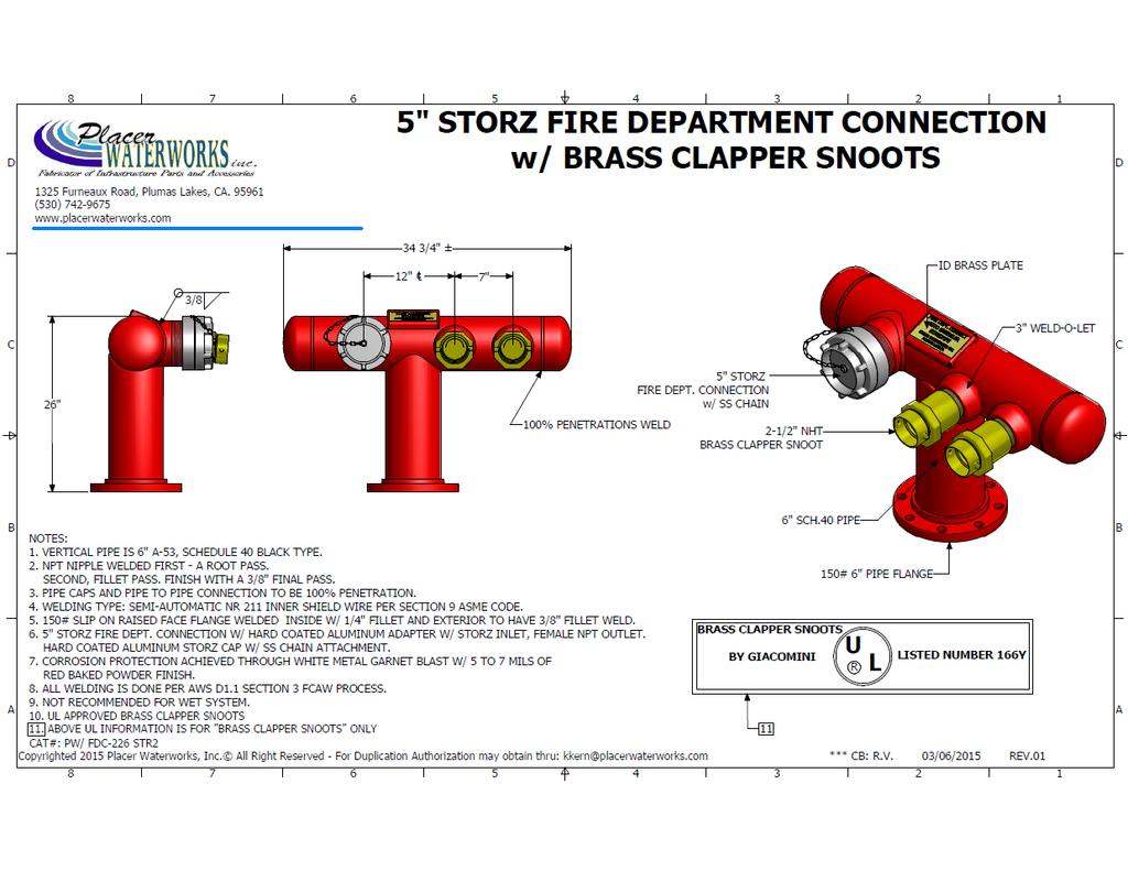
69 69
EL DORADO COUNTY REGIONAL FIRE PROTECTION STANDARD
 EL DORADO COUNTY REGIONAL FIRE PROTECTION STANDARD Installation of Residential Fire Sprinkler Systems STANDARD #C-002 EFFECTIVE 03-19-2009 PURPOSE: To ensure that sprinkler plans submitted for review contain
AUTOMATIC FIRE SPRINKLER SYSTEM STANDARDS Development Standard #4.1 (Commercial Installations)
") AUTOMATIC FIRE SPRINKLER SYSTEM STANDARDS Development Standard #4.1 (Commercial Installations) This standard applies to the design and installation of automatic fire sprinkler systems in conjunction with
AUTOMATIC FIRE SPRINKLER SYSTEM STANDARDS Development Standard #4.1 (Commercial Installations) This standard applies to the design and installation of automatic fire sprinkler systems in conjunction with
CITY OF PASADENA FIRE DEPARTMENT
 Page 1 of 8 CITY OF PASADENA FIRE DEPARTMENT INSTALLATION OF COMMERCIAL SPRINKLERS (Revised 12/10/2014) SCOPE: This standard applies to the design and installation of automatic fire sprinkler systems in
FIRE SPRINKLER SYSTEMS POLICY
 FIRE SPRINKLER SYSTEMS POLICY Revised 1/1/17 DESIGN AND SUBMITTAL REQUIREMENTS All new and existing fire sprinkler systems within the jurisdiction of the City Fire Department shall meet all of the applicable
New Construction Fire Inspection Process
 New Construction Fire Inspection Process This document is intended to provide the Owner, Designer, and/or Contractor of new construction with an outline of required fire inspections and with the specific
FIRE SPRINKLER SYSTEMS POLICY
 FIRE SPRINKLER SYSTEMS POLICY VERSION 1.012/2015 FIRE SPRINKLER SYSTEMS Design and Submittal requirements All new and existing fire sprinkler systems within the jurisdiction of the City of San Mateo Fire
FIRE PREVENTION OFFICE Placer Hills Fire Protection District NEW PROJECT GUIDELINES
 Established 1949 FIRE PREVENTION OFFICE Placer Hills Fire Protection District NEW PROJECT GUIDELINES The following are guidelines for new development. Any submitted plans must comply with these guidelines,
Fire & Life Safety Supplemental Rules & Regulations for New Construction & Significant Remodels
 DEPARTMENT OF PUBLIC SAFETY FIRE MARSHAL S OFFICE 9611 SE 36 TH ST Mercer Island, WA 98040 (206) 236-3515 direct; (206) 236-3622 FAX Rod Mandery, Fire Marshal Updated version: 03-19-2002 Fire & Life Safety
MONTECITO FIRE PROTECTION DISTRICT
 Section 5a MONTECITO FIRE PROTECTION DISTRICT FIRE PROTECTION PLAN Residential Automatic Fire Sprinkler System Installations I Automatic Fire Sprinkler System Standards 1. Definition and Standard: An automatic
EL DORADO COUNTY REGIONAL FIRE PROTECTION STANDARD
 EL DORADO COUNTY REGIONAL FIRE PROTECTION STANDARD INSTALLATION OF COMMERCIAL FIRE SPRINKLER SYSTEMS STANDARD #C-001 EFFECTIVE 03-25-2009 PURPOSE: To ensure that sprinkler plans submitted for review contain
This guide is intended to provide assistance in the application of the fire code in all areas served by Tualatin Valley Fire & Rescue.
 This guide is intended to provide assistance in the application of the fire code in all areas served by Tualatin Valley Fire & Rescue. North Operating Center 11945 SW 70 th Avenue Tigard, OR 97223 Phone:
Fire & Life Safety Requirements For Fire Department Access and Water Supplies
 Fire & Life Safety Requirements For Fire Department Access and Water Supplies This brochure is being provided as a resource only. The items listed inside are the requirements most generally cited on plans
International Fire Code 2006 Requirements for Construction Plan Reviews of Commercial and Multi-Family Structures
 International Fire Code 2006 Requirements for Construction Plan Reviews of Commercial and Multi-Family Structures Please note this is not an all-inclusive list. The type and complexity of your project
FIRE SERVICE FEATURES
 CHAPTER 5 FIRE SERVICE FEATURES SECTION 501 GENERAL 501.1 Scope. Fire service features for buildings, structures and premises shall comply with this chapter. 501.2 Permits. A permit shall be required as
City of Vista Fire Department
 City of Vista Fire Department Development Services Section 600 Eucalyptus Avenue, Vista CA 92084 Guideline: Underground Piping for Private Fire Hydrants & Fire Sprinkler Supply. Updated: January, 2008
AUTOMATIC FIRE SPRINKLER SYSTEMS
 MCKINNEY FIRE DEPARTMENT FIRE MARSHAL S OFFICE AUTOMATIC FIRE SPRINKLER SYSTEMS These guidelines are to be followed when a business, facility or organization installs an automatic fire sprinkler system
GLENDALE FIRE DEPARTMENT FIRE MARSHAL S OFFICE
 GLENDALE FIRE DEPARTMENT FIRE MARSHAL S OFFICE To: From: Subject: Whom It May Concern Carl Ray Austerman, Fire Marshal Contractor s Guide Welcome to the Glendale Fire Department s Contractors Guide. This
Fire District Dwelling Construction Requirements
 Fire District Dwelling Construction Requirements Includes Sacramento County Fire Marshals Association Standard for Residential Sprinklers City of Rancho Cordova Building & Safety Department 2729 Prospect
RESIDENTIAL FIRE SPRINKLER SYSTEMS POLICY
 RESIDENTIAL FIRE SPRINKLER SYSTEMS POLICY Plan Submittal and Inspection Requirements Revised 01/18/18 All residential fire sprinkler systems within the jurisdiction of the Fire Department shall meet all
TRI-LAKES MONUMENT FIRE PROTECTION DISTRICT
 TRI-LAKES MONUMENT FIRE PROTECTION DISTRICT LOCAL AMENDMENTS INTERNATIONAL FIRE CODE 2009 December 5, 2012 1 Chapter 1 Administration Chapter 5 Fire Service Features Chapter 9 Fire Protection Systems Chapter
FIRE & LIFE SAFTEY STANDARD
 Title: Effective Date: 01/01/14 Revised Date: 1/1/14 Code References: Title 16, Chapter 16.16 of the Roseville Municipal Code, NFPA 72 Note: This standard is a summary of Fire Department clarifications
TABLE OF CONTENTS ADOPTED FIRE CODES... 3 AFPD SERVICE AREA... 3 SITE AND DEVELOPMENT SUBMITTAL REQUIREMENTS... 4 PLAN REVIEW FEES...
 TABLE OF CONTENTS ADOPTED FIRE CODES... 3 AFPD SERVICE AREA... 3 SITE AND DEVELOPMENT SUBMITTAL REQUIREMENTS... 4 PLAN REVIEW FEES... 4 SITE AND DEVELOPMENT PLAN REVIEW TURNAROUND TIMES... 4 DEVELOPMENT
FIRE APPARATUS ACCESS AND WATER SUPPLY GUIDELINE
 City of Conroe Fire Department Fire Marshal s Office 300 W. Davis 1 st Floor Conroe, Texas 77301 T: (936) 522-3080 F: (936) 522-3079 firecodes@cityofconroe.org FIRE APPARATUS ACCESS AND WATER SUPPLY GUIDELINE
SANTA ROSA FIRE DEPARTMENT FIRE PREVENTION BUREAU PLAN REVIEW CHECKLIST STANDPIPE SYSTEMS
 July 1, 2010 SANTA ROSA FIRE DEPARTMENT FIRE PREVENTION BUREAU PLAN REVIEW CHECKLIST STANDPIPE SYSTEMS Address: Permit #: Inspector: Date Inspected: Status: Inspector: Date Inspected: Status: A-Approved;
HIGH-RISE RETROFIT ORDINANCES - NO and NO
 INFORMATION BULLETIN / PUBLIC - BUILDING CODE REFERENCE NO.: LAMC 91.8604 Effective: 9-06-90 DOCUMENT NO. P/BC 2002-054 Revised: 4-15-03 Previously Issued As: MGD 88 HIGH-RISE RETROFIT ORDINANCES - NO.
VACAVILLE FIRE PROTECTION DISTRICT 420 Vine Street Vacaville, California (707)
") VACAVILLE FIRE PROTECTION DISTRICT 420 Vine Street Vacaville, California 95688 (707) 447-2252 Requirements for new construction within the boundaries of the Vacaville Fire Protection District include,
VACAVILLE FIRE PROTECTION DISTRICT 420 Vine Street Vacaville, California 95688 (707) 447-2252 Requirements for new construction within the boundaries of the Vacaville Fire Protection District include,
Bold items are particular to the City of Euless
 EULESS FIRE DEPARTMENT FIRE MARSHAL S OFFICE INFORMATION LINE: Revised 8/2004 Fire Chief Lee Koontz Fire Marshal Paul Smith EFD-FMO 3-1 2003 International Fire & Building Code as Amended NFPA Standards
EXHIBIT A STEAMBOAT SPRINGS FIRE PREVENTION SERVICES ADMINISTRATIVE POLICY & PROCEDURE MANUAL
 EXHIBIT A STEAMBOAT SPRINGS FIRE PREVENTION SERVICES ADMINISTRATIVE POLICY & PROCEDURE MANUAL SECTION: 4 POLICY NO.: 1257.1 DATE: April 1, 2006 PAGE: 1 SUBJECT: Fire Apparatus Access Road Standards for
FIRE PLAN CHECK CORRECTION List for Commercial Occupancies
 PASS / RESUBMIT Rancho Santa Fe Fire Protection District P.O. Box 410 18027 Calle Ambiente Rancho Santa Fe California 92067-0410 Tel. (858) 756-5971 Fax (858) 756-4799 FIRE PLAN CHECK CORRECTION List for
4/13/2015. Everything a firefighter wants to tell a design professional or building code official, in one hour.
 Everything a firefighter wants to tell a design professional or building code official, in one hour. 1 2 3 1 4 The job of the fire department is to put the wet stuff on the red stuff. 5 Job #1. of the
C I T Y O F B A N N I N G BANNING FIRE SERVICES 3900 W. WILSON STREET (951) PHONE (951) FAX
 PHONE (951) FAX") C I T Y O F B A N N I N G BANNING FIRE SERVICES 3900 W. WILSON STREET (951) 922-3210 - PHONE (951) 922-0318 - FAX CITY OF BANNING FIRE SERVICES STANDARD CONDITIONS OF APPROVAL FOR RESIDENTIAL BUILDINGS
C I T Y O F B A N N I N G BANNING FIRE SERVICES 3900 W. WILSON STREET (951) 922-3210 - PHONE (951) 922-0318 - FAX CITY OF BANNING FIRE SERVICES STANDARD CONDITIONS OF APPROVAL FOR RESIDENTIAL BUILDINGS
Rancho Cucamonga Fire Protection District Prevention Bureau Standard
 Rancho Cucamonga Fire Protection District Prevention Bureau Standard Title: Fire Alarm and Monitoring Systems Standard # 9-3 Effective: May 2002 Number of Pages: 7 Updated: December 2016 for consistency
SANTA ROSA FIRE DEPARTMENT FIRE PREVENTION BUREAU PLAN REVIEW CHECKLIST
 July 1, 2010 SANTA ROSA FIRE DEPARTMENT FIRE PREVENTION BUREAU PLAN REVIEW CHECKLIST TENANT IMPROVEMENTS Address: Permit #: Inspector: Date: Status: Inspector: Date: Status: A-Approved; AC-Approved w/comments;
SANTA CLARA COUNTY Winchester Blvd., Los Gatos, CA (408) (408) (fax)
 (408) (fax)") FIRE DEPARTMENT SANTA CLARA COUNTY 14700 Winchester Blvd., Los Gatos, CA. 95032-1818 (408) 378-4010 (408) 378-9342 (fax) www.sccfd.org STANDARD DETAILS & SPECIFICATIONS Spec No C-4 Rev. Date 03/10/10 SUBJECT:
FIRE DEPARTMENT SANTA CLARA COUNTY 14700 Winchester Blvd., Los Gatos, CA. 95032-1818 (408) 378-4010 (408) 378-9342 (fax) www.sccfd.org STANDARD DETAILS & SPECIFICATIONS Spec No C-4 Rev. Date 03/10/10 SUBJECT:
SECTION WET-PIPE SPRINKLER SYSTEMS
 SECTION 21 13 13 WET-PIPE SPRINKLER SYSTEMS PART 1 - GENERAL 1.1 SCOPE OF WORK A. Design, installation and testing shall be in accordance with NFPA 13 except for specified exceptions. B. The demolition
Module 3. Water-Based Suppression Systems (WBSS) Part II: Highlights of Code Requirements
 Part II: Highlights of Code Requirements") Module 3 Water-Based Suppression Systems (WBSS) Part II: Highlights of Code Requirements 1 WATER-BASED SUPPRESSION SYSTEMS-PART TWO This module covers: 1. Ohio Building Code requirements and when and why
Module 3 Water-Based Suppression Systems (WBSS) Part II: Highlights of Code Requirements 1 WATER-BASED SUPPRESSION SYSTEMS-PART TWO This module covers: 1. Ohio Building Code requirements and when and why
SANTA ROSA FIRE DEPARTMENT FIRE PREVENTION BUREAU STANDARD
 July 1, 2010 SANTA ROSA FIRE DEPARTMENT FIRE PREVENTION BUREAU STANDARD STANDPIPE SYSTEMS PURPOSE This standard outlines the general requirements for the installation of standpipe systems. CODE REFERENCES
CLARK COUNTY FIRE DEPARTMENT Fire Prevention Bureau
 CLARK COUNTY FIRE DEPARTMENT Fire Prevention Bureau 575 E. Flamingo Road, Las Vegas, NV 89119 (702) 455-7316 FAX (702) 455-7347 Permit Type: 105.7.13 Control Number: A.0 Effective Date: 11/15/11 TITLE:
GLENDALE FIRE DEPARTMENT FIRE MARSHAL S OFFICE
 GLENDALE FIRE DEPARTMENT FIRE MARSHAL S OFFICE To: Contractors From: Charles Jenkins, Fire Marshal Subject: Contractor s Guide This guide is provided by the Fire Marshal as a service to the construction
Montgomery County Government Building and Codes Department 350 Pageant Lane, Suite 309 Clarksville, TN 37040
 Montgomery County Government Building and Codes Department 350 Pageant Lane, Suite 309 Clarksville, TN 37040 SPRINKLER SHOP DRAWINGS 2007 NFPA 13 and 2007 NFPA 24 Project: Listed items require sprinkler
TETON COUNTY FIRE PROTECTION RESOLUTION FOR NEW SUBDIVISIONS 2008 Edition. Chapter I General Provisions
 TETON COUNTY FIRE PROTECTION RESOLUTION FOR NEW SUBDIVISIONS 2008 Edition Chapter I General Provisions SECTION 1.1: TITLE. This Resolution shall be known as the Teton County Fire Protection Resolution
Sprinkler Permit Applications
 REQUIREMENTS FOR NFPA 13 SYSTEM Building Inspections Sprinkler Permit Applications A complete application for a Sprinkler Permit will comply with the requirements of Chapter 8 of NFPA 13. Hydraulic calculations
SANTA ROSA FIRE DEPARTMENT FIRE PREVENTION BUREAU INSPECTION CHECKLIST
 July 1, 2010 SANTA ROSA FIRE DEPARTMENT FIRE PREVENTION BUREAU INSPECTION CHECKLIST FIRE AND LIFE SAFETY SYSTEMS FOR STRUCTURES FIVE OR MORE STORIES IN HEIGHT AND LESS THAN 75 FEET IN HEIGHT FROM THE POINT
Fire Sprinkler System Design and Installation Requirements
 Fire Sprinkler System Design and Installation Requirements The Park City Fire Service District (PCFD) and Park City Municipal Corporation (PCMC) have made the following amendments to the State of Utah
FIRE CODE APPLICATION GUIDE FOR DEVELOPMENT IN UNINCORPORATED MULTNOMAH COUNTY
 FIRE CODE APPLICATION GUIDE FOR DEVELOPMENT IN UNINCORPORATED MULTNOMAH COUNTY This guide is intended to provide assistance in the application of the fire code in Unincorporated Multnomah County. October
EXHIBIT A STEAMBOAT SPRINGS FIRE PREVENTION SERVICES ADMINISTRATIVE POLICY & PROCEDURE MANUAL
 EXHIBIT A STEAMBOAT SPRINGS FIRE PREVENTION SERVICES ADMINISTRATIVE POLICY & PROCEDURE MANUAL SECTION: 4 POLICY NO.: 1258.1D DATE: September 11, 2006 PAGE: 1 SUBJECT: Fire Apparatus Access Road Standards
Moreno Valley Fire Department Fire Prevention Bureau. New and Existing Fire Alarm & Signaling Systems Guideline
 Moreno Valley Fire Department Guideline Approved and Authorized By: Adria Reinertson, Fire Marshal Issued: May 8, 2017 Alarm & Signaling Systems PURPOSE Fire alarm and signaling systems are designed to
FIRE PREVENTION STANDARDS
 DATE: 04/11/02 APPROVED: NUMBER: FP0-010 REVISED: FIRE PREVENTION STANDARDS TITLE: Large Family Day Cares (9-14 kids) PURPOSE: The purpose of this standard is to acquaint the applicant with the applicable
MINOOKA FIRE PROTECTION DISTRICT Fire Prevention Bureau Fire Inspector Rodney Bradberry
 MINOOKA FIRE PROTECTION DISTRICT Fire Prevention Bureau Fire Inspector Rodney Bradberry Fire Alarm Systems Plan Review Checklist Date: Permit Number: Business Name: Address: Fire Alarm System Submittal
PINETOP FIRE DEPARTMENT TIMBER MESA FIRE AND MEDICAL DISTRICT
 Amendments for 2015 IFC CHAPTER 1 SCOPE AND ADMINISTRATION Section 101.2.1 Appendices. All appendices to be adopted Section 113.2 Schedule of permit fees. Is AMENDED to read: A fee for each permit shall
S000 SITE REVIEW APPR NO. FIRE CODE COMPLIANCE ITEM
 APPR NO. FIRE CODE COMPLIANCE ITEM S000 S001 S005 (Automobile Access Aisle) shall be a minimum of 5 ft wide, a common access aisle may be shared by 2 vehicles. Surface slopes shall not exceed 1:50(2%)
Site Plans. Fire Code Requirements
 Site Plans Fire Code Requirements Outline Before you start Critical building information drives requirements Access Requirements Access, aerial access, road design, remoteness, fire lanes, residential
Rocky Mountain Fire Protection District 4390 Eldorado Springs Drive Boulder, CO
 Rocky Mountain Fire Protection District 4390 Eldorado Springs Drive Boulder, CO 80303 303-494-3735 Contractor s Checklist and Installation Guide TABLE OF CONTENTS Fire Protection Narrative........... 3
Chapter 2: Identification, water and access
 Chapter 2: Identification, water and access As you are approaching the occupancy to be inspected, take note of building and fire protection services. Put yourself in the shoes of a first arriving company
Oxnard Fire Department 360 W. Second Street Oxnard, CA (805) Fax (805)
 Fax (805)") Oxnard Fire Department 360 W. Second Street Oxnard, CA 93030 (805) 385-7722 Fax (805) 385-8009 FIVE YEAR CERTIFICATION REPORT Service and maintenance report for automatic fire extinguishing systems, including
Oxnard Fire Department 360 W. Second Street Oxnard, CA 93030 (805) 385-7722 Fax (805) 385-8009 FIVE YEAR CERTIFICATION REPORT Service and maintenance report for automatic fire extinguishing systems, including
Division 21: FIRE SUPRESSION WET-PIPE SPRINKLER PROTECTION SYSTEM. The Academy Sept Table of Contents 1 Division 21
 Division 21: FIRE SUPRESSION 21 1313 WET-PIPE SPRINKLER PROTECTION SYSTEM Table of Contents 1 Division 21 SECTION 21 1313 WET-PIPE SPRINKLER PROTECTION SYSTEM PART 1 - GENERAL 1.1 RELATED DOCUMENTS A.
CubeSmart Gulf Breeze Storage AUTOMATIC FIRE SPRINKLER SYSTEM
 SECTION 21 0000 AUTOMATIC FIRE SPRINKLER SYSTEM PART 1 GENERAL 1.1 QUALITY ASSURANCE A. Codes and Standards: 1. FBC (Florida Building Code 2015) 2. FBC (Florida Fire Code 2015) 3. NFPA #13R (Standard for
Port of St Helens SIA Aircraft Hanger Scappoose, OR
 Port of St Helens SIA Aircraft Hanger Scappoose, OR AUTOMATIC FIRE SPRINKLER SYSTEM REVISION 2 MARCH 12, 2018 Scope: Furnish and install foam and water fire protection system including underground entrance
TAMARAC FIRE RESCUE DEPARTMENT FIRE PREVENTION BUREAU 6000 North Hiatus Road Tamarac, Florida Telephone: (954) , Fax: (954)
 , Fax: (954)") TAMARAC FIRE RESCUE DEPARTMENT FIRE PREVENTION BUREAU 6000 North Hiatus Road Tamarac, Florida 33321 Telephone: (954) 597-3800, Fax: (954) 597-3810 SITE PLAN REVIEW CHECKLIST A goal of the Tamarac Fire
TAMARAC FIRE RESCUE DEPARTMENT FIRE PREVENTION BUREAU 6000 North Hiatus Road Tamarac, Florida 33321 Telephone: (954) 597-3800, Fax: (954) 597-3810 SITE PLAN REVIEW CHECKLIST A goal of the Tamarac Fire
APPENDIX H (DESIGN SUBMISSION CRITERIA)
") APPENDIX H (DESIGN SUBMISSION CRITERIA) FIRE ALARM SYSTEM As per ACCORD standard Part 5, section 5.7 Fire Alarm System Design to be verified by ACCORD Chief Safety Inspector. Testing of the installation
APPENDIX H (DESIGN SUBMISSION CRITERIA) FIRE ALARM SYSTEM As per ACCORD standard Part 5, section 5.7 Fire Alarm System Design to be verified by ACCORD Chief Safety Inspector. Testing of the installation
Residential-based Care Facility R-4 Guideline
 Moreno Valley Fire Department Fire Prevention Bureau Residential-based Care Facility R-4 Guideline Approved and Authorized By: Adria Reinertson, Fire Marshal Issued: April 7, 2017 Residential-based Care
Access Aisle (Van) (Flow Test) Water Mains (Location & Sizes) Building Entrances. Building, Facilities, Element. Curb Ramps (Built-up)
 (Flow Test) Water Mains (Location & Sizes) Building Entrances. Building, Facilities, Element. Curb Ramps (Built-up)") GWINNETT COUNTY Department of Fire & Emergency Services Office of the Fire Marshall S001 Access Aisle (Car) S005 S010 S015 S020 S025 S030 S035 S040 S045 S050 S055 S060 S065 S070 S075 S080 S085 Access Aisle
GWINNETT COUNTY Department of Fire & Emergency Services Office of the Fire Marshall S001 Access Aisle (Car) S005 S010 S015 S020 S025 S030 S035 S040 S045 S050 S055 S060 S065 S070 S075 S080 S085 Access Aisle
FIRE PLAN CHECK FORM/CORRECTION List for Single Family Residences, Duplexes, and Garages
 City of Escondido Fire Department 1163 N Centre City Parkway Escondido, CA 92026 Phone: 760-839-5400 FAX: 760-739-7060 PASS / RESUBMIT FIRE PLAN CHECK FORM/CORRECTION List for Single Family Residences,
Chapter 4: Fire Protection Systems
 Chapter 4: Fire Protection Systems Automatic Extinguishing Systems (Fire Sprinklers) One of the most important aspects of a storage warehouse inspection is ensuring that the automatic extinguishing system
PLAN REVIEW CHECKLIST
 PLAN REVIEW CHECKLIST Date Documents Submitted: Log No.: File No.: Property Information Building Name: Building Address: Owner s Name: Owner s Address: Owner s Phone: Fax: E-mail: System Designer/Contractor
CITY OF LONG BEACH Department of Development Services BUILDING AND SAFETY BUREAU FIRE ALARM / ELECTRICAL FIRE PLAN REVIEW CHECKLIST
 CITY OF LONG BEACH Department of Development Services BUILDING AND SAFETY BUREAU FIRE ALARM / ELECTRICAL FIRE PLAN REVIEW CHECKLIST DATE: PROJECT NO.: EXPIRATION DATE: STATUS: INFORMATION PROJECT ADDRESS:
CITY OF MADISON FIRE DEPARTMENT (MFD) FIRE PROTECTION SYSTEM PLANS
 FIRE PROTECTION SYSTEM PLANS") CITY OF MADISON FIRE DEPARTMENT (MFD) FIRE PROTECTION SYSTEM PLANS Fire Protection Systems includes the following: Alternate Fire Suppression Systems Atrium Fire Protection Systems Automatic Fire Sprinkler
CITY OF MADISON FIRE DEPARTMENT (MFD) FIRE PROTECTION SYSTEM PLANS Fire Protection Systems includes the following: Alternate Fire Suppression Systems Atrium Fire Protection Systems Automatic Fire Sprinkler
2. The Group F occupancy has have an a combined occupant load of 500 or more above or below the lowest level of exit discharge.
 2. The Group F occupancy has have an a combined occupant load of 500 or more above or below the lowest level of exit discharge. Exception: Manual fire alarm boxes are not required where the building is
DESIGN & CONSTRUCTION GUIDELINES
 ADMINISTRATIVE SERVICES 4202 E. FOWLER AVENUE, FPC110 PHONE: (813) 974-2625 FACILITIES PLANNING & CONSTRUCTION TAMPA, FLORIDA 33620-7550 WEBSITE: USF.EDU/FPC DESIGN & CONSTRUCTION GUIDELINES DIVISION 21
DIVISION 21 - FIRE SUPPRESSION
 DIVISION 21 - FIRE SUPPRESSION DESIGN CRITERIA It is the policy of UC Davis to install fire sprinkler systems in all new construction/facilities. If the building is classified as a pole barn, shed, carport,
SECTION FIRE-SUPPRESSION STANDPIPES
 PART 1 - GENERAL 1.1 DESCRIPTION Fire-suppression wet and manual dry standpipes. 1.2 SCOPE OF WORK SECTION 21 12 00 A. Design, installation and testing shall be in accordance with NFPA 14 except for specified
C. All components of the systems described shall meet the requirements as stated herein and shall be approved by the Architect and Consultant.
 SECTION 218800 - FIRE PROTECTION 1. GENERAL A. Provisions of Division 1, GENERAL REQUIREMENTS, and Section 230000, MECHANICAL GENERAL CONDITIONS, and Section 230050, SEISMIC PROTECTION are a part of this
FIRE CODE. Coal City Fire District International Fire Code Update. 35 S. DeWitt Place Coal City, IL
 . 2015 FIRE CODE 2015 International Fire Code Update Coal City Fire District 35 S. DeWitt Place Coal City, IL 60416 815-634-4700 Table of Contents SECTION 109 VIOLATIONS... 3 SECTION 111 STOP WORK ORDER...
To provide the requirements needed for Care Facilities Having 6 or Fewer Clients. This occupancy is classified as an R-3.1.
 EL DORADO COUNTY REGIONAL FIRE PROTECTION STANDARD STANDARD #F-003 EFFECTIVE 06-03-2009 PURPOSE To provide the requirements needed for Care Facilities Having 6 or Fewer Clients. This occupancy is classified
FIRE SPRINKLER SHOP DRAWING SUBMITTAL REQUIREMENTS
 Department of Fire Rescue & Emergency Services Fire Marshal s Office Dania Beach District 103 West Dania Beach Blvd. Dania Beach, Florida 33004 Office: (954)342-4262 Fax: (954)342-4265 FIRE SPRINKLER SHOP
CLARK COUNTY FIRE DEPARTMENT Fire Prevention Bureau
 CLARK COUNTY FIRE DEPARTMENT Fire Prevention Bureau 575 E. Flamingo Road, Las Vegas, NV 89119 (702) 455-7316 FAX (702) 455-7347 Permit Type: 105.7.14 Control Number: A.0 Effective Date: 9/14/11 TITLE:
GENERAL AREAS OF INSPECTION
 This information is intended to assist you in preparation for the annual high-rise inspection. This is not a complete list and the Inspector may identify other conditions or issues in the building that
FIRE SERVICE FEATURES
 CHAPTER 5 FIRE SERVICE FEATURES SECTION 501 GENERAL 501.1 Scope. Fire service features for buildings, structures and premises shall comply with this chapter. 501.2 Permits. A permit shall be required as
APPLICATION FOR Large Family Day Care Permit
 PLANNING SERVICES DEPARTMENT 411 Main Street (530) 879-6800 P.O. Box 3420 Chico, CA 95927 Application No. APPLICATION FOR Large Family Day Care Permit Applicant Information Applicant Daytime Phone Street
FIRE ALARM APPLICATION CITY OF MADISON HEIGHTS
 FIRE ALARM APPLICATION CITY OF MADISON HEIGHTS www.madison-heights.org COMMUNITY DEVELOPMENT DEPARTMENT BUILDING DIVISION 300 W. THIRTEEN MILE RD. MADISON HEIGHTS, MICHIGAN 48071 (248) 583-0831 FAX (248)
S a n F r a n c i s c o F i r e D e p a r t m e n t B u r e a u o f F i r e P r e v e n t i o n & I n v e s t i g a t i o n 1 of 8 P a g e
 5.07 Air Replenishment Systems (2016) Reference: SFFC, Section 511.2. Purpose: The purpose of this bulletin is to describe the requirements for air replenishment systems intended to be used to fill firefighters'
Fire Sprinkler Plan Submittal Form
 Contents Fire Sprinkler Plan Submittal Form... 2 Standpipe Plan Review Submittals... 4 Fire Pump Plan Submittal Requirements... 6 Fire Alarm Plan Submittal Form... 8 Kitchen Hood Wet Chemical Submittal...10
To expedite the plan review and inspection processes, please refer to the information below.
 Guidelines: The goal of the Denison Fire Department is to assist its customers in understanding our submittal, plan review and inspection process and policies, as they pertain to new construction. Familiarity
SANTA ROSA FIRE DEPARTMENT FIRE PREVENTION BUREAU STANDARD
 July 1, 2010 SANTA ROSA FIRE DEPARTMENT FIRE PREVENTION BUREAU STANDARD LICENSED CARE FACILITIES SCOPE: This standard provides requirements for licensed care facilities known as for the Elderly with seven
5.07 Air Replenishment Systems
 5.07 Air Replenishment Systems Reference: 2010 SFFC, Section 511.2 Definitions: CERTIFIED COMPRESSOR. A compressor used by a contractor for maintenance and testing of air replenishment systems that is
CHAPTER 7 ALTERATIONS LEVEL
 CHAPTER 7 ALTERATIONS LEVEL 2 SECTION 701 GENERAL 701.1 Scope. Level 2 alterations as described in Section 404 shall comply with the requirements of this chapter. Exception: Buildings in which the reconfiguration
Commercial Rules and Regulations
 Commercial Rules and Regulations Public Works and Community Development Department City of Shenandoah 29955 I 45 North Shenandoah, Texas 77381 281 298 5522 www.shenandoahtx.us Construction Documents Submit
UBC Technical Guidelines Section Edition Fire Protection General Requirements Page 1 of 6
 Page 1 of 6 1.0 GENERAL 1.1 Related UBC Guidelines.1 Section 20 00 05 Mechanical - General Requirements.2 Section 22 05 00 Plumbing - General Requirements.3 UBC Standard Fire Hydrant Drawings.4 Section
FIRE PREVENTION CODE
 164.01 Purpose 164.03 Amendments to Fire Prevention Code 164.02 Adoption of Fire Prevention Code 164.04 Board of Appeals 164.01 PURPOSE. The purpose of this chapter is to prescribe regulations governing
Norfolk Fire Department Fire Prevention & Information
 Norfolk Fire Department Fire Prevention & Information For Permits and Inspections Contact (508)528-3207 EFFECTIVE JANUARY 1, 2015, THE NORFOLK FIRE DEPARTMENT, BY STATE REGULATIONS, NO LONGER ISSUES PERMITS
CONTRACT FOR USE OF FIRE PROTECTION SYSTEM
 CONTRACT FOR USE OF FIRE PROTECTION SYSTEM THIS AGREEMENT made and entered on this the day of, 20 by and between its successors and assigns, hereinafter referred to as Customer and the Jessamine County
Drexel Heights Fire District 2012 International Fire Code Amendments
 February 15, 2013 Drexel Heights Fire District adopted the International Fire Code 2012 edition in its entirety unless otherwise amended below. CHAPTER 1 SCOPE AND ADMINISTRATION SECTION 101 SCOPE AND
Construction & Development Procedures Guide
 Construction & Development Procedures Guide Updated December 2018 TABLE OF CONTENTS Welcome to Front Range Fire Rescue... 3 About This Guide... 3 Getting Started: Planning Approval and Building Permit
This guide is intended to provide assistance in the application of the fire code in all areas served by Tualatin Valley Fire & Rescue.
 This guide is intended to provide assistance in the application of the fire code in all areas served by Tualatin Valley Fire & Rescue. North Operating Center 11945 SW 70 th Avenue Tigard, OR 97223 Phone:
Construction and Development Guide
 Construction and Development Guide **Based on the 2014 Indiana Fire Prevention Code and relevant NFPA Codes and Standards ** Copyright 2018 Clay Fire CRRD 1 P a g e Table of Contents Map of Jurisdiction...
Commercial Remodel/ Add On Rules and Regulations
 Commercial Remodel/ Add On Rules and Regulations Public Works and Community Development Department City of Shenandoah 29955 I-45 North Shenandoah, Texas 77381 281-298-5522 www.shenandoahtx.us Construction
DIVISION 21 - FIRE SUPPRESSION
 DIVISION 21 - FIRE SUPPRESSION DESIGN CRITERIA It is the policy of UC Davis to install fire sprinkler systems in all new construction/facilities. If the building is classified as a pole barn, shed, carport,
2.07 Permit Application Checklist for Diesel Generators, Diesel Fire Pumps, and Fuel Tanks Serving Generators and Fire Pumps (2016)
") 2.07 Permit Application Checklist for Diesel Generators, Diesel Fire Pumps, and Fuel Tanks Serving Generators and Fire Pumps (2016) Reference: Documents referenced for this bulletin are as follows: San
2.07 Permit Application Checklist for Diesel Generators, Diesel Fire Pumps, and Fuel Tanks Serving Generators and Fire Pumps (2016) Reference: Documents referenced for this bulletin are as follows: San
Residential Care Facilities Having 6 or Fewer Clients Classified in the California Building Code as R-3.1 Occupancies
 Building Permits & Inspection Division General Information: (916) 875-5296 www.building.saccounty.net Full Service Center 827 7th Street, Room 102 Sacramento, CA 95814 M-F 8:30am - 4:30pm Bradshaw Center
Florida Building Code 2010
 Introduction Florida Building Code 2010 Chapter 9 Fire Protection Systems This course will cover specific sections of Chapter 9 that relate to fire alarm systems. While many contractors are familiar with