Setup Instructions. This manual is only valid for A36D/TPSD Chargers. equipped with a 341S control card with P341S0012 or P341S0013 software
|
|
|
- Neil Neal
- 6 years ago
- Views:
Transcription

1 La Marche Manufacturing Company DNP 3.0 Serial (RS232/RS485) and Ethernet (TCP/IP) SCADA Interface for A36D & TPSD Chargers with S2A-341S and S2A-383S communication cards. Option 21P, 57T and 57U Setup Instructions This manual is only valid for A36D/TPSD Chargers equipped with a 341S control card with P341S0012 or P341S0013 software and 383S-3X6X communications card with P383S-21P6-01 software or 383DS-3X6X communication card with P383DS-57TU6-01 software. 106 Bradrock Dr. Des Plaines, IL Tel: Fax: CPN Instruction Drawing Number: P25-LOPT21P57TU-A36D-TPSD-1-341S Revision A02 Rev. Date: 12/17 ECN:
2 Default Settings The LaMarche Communications Card is shipped with the following default settings: Node Address: 4 Serial Port Settings Port: RS485 Baud Rate: 9600 Data Bits: Fixed at 8 Stop Bits: Fixed at 1 Parity: Ethernet/TCP/Configuration Port Settings IP Address: Subnet: Gateway: TCP Port Number: Communications Setting Configuration Enter the Settings Menu and scroll to the Comm. Settings selection. Within the Comm. Settings menu you may choose the following selections; DNP Node Address DNP Serial Port DNP Parity DNP Baud Rate DNP IP Address DNP Subnet Mask DNP Gateway DNP TCP Port Number Read Only Mode < DNP > Node Address This allows you to set the Node Address. The address is set in individual digits. Use the UP and DOWN ARROW buttons to increment or decrement the digit. Use the CHARGER MODE button to advance to the next digit. Press ENTER to complete the selection or the BACK to discard. Valid settings are 0 to
 selects RS232 or RS485.")
3 < DNP Serial Port Type > Selects the type of serial port. Selections are RS232 or RS485. Note dipswitch setting changes are required on the communications board. Use the UP and DOWN ARROW buttons to make the selection. Press ENTER to complete the selection or the BACK to discard. SERIAL PORT SELECTION SW4 (light blue) selects RS232 or RS485. SW3 (red) selects the BIAS and TERMINATION resistor configuration for RS485. There is no selection for the TCP Port as that is active all of the time. The RS232 port is wired as DTE. 3
4 < DNP Parity Type > Selects the Parity type. Selections are NONE, ODD, EVEN. Use the UP and DOWN ARROW buttons to make the selection. Press ENTER to complete the selection or the BACK to discard. < DNP Baud Rate > Selects the Baud Rate. Selections are 1200, 2400, 4800, 9600, 19200, Use the UP and DOWN ARROW buttons to make the selection. Press ENTER to complete the selection or the BACK to discard. < Read Only Mode > This selection when set to YES prevents ALL settings changes from being made remotely. All the settings may be read but none may be written to. The only way to modify this selection is from the front panel of the charger. Use the UP and DOWN ARROW buttons to make the selection. Press ENTER to complete the selection or the BACK to discard. < DNP IP Address > Selects the IP Address. The IP Address is set in individual quads. Use the UP and DOWN ARROW buttons to increment or decrement the quad value. Use the CHARGER MODE button to advance to the next quad. Press ENTER to complete the selection or the BACK button to discard. Valid IP settings are as follows; 1) The Subnet Mask must be valid 2) The IP may not be the loopback address of ) The IP may not be in the Class D range of to ) The IP may not be in the Class E range of to ) The IP may not be a broadcast address of or ) The IP and Gateway must be in the same Subnet < DNP > Subnet Mask Selects the Subnet Mask. The Subnet Mask is set in individual quads. Use the UP and DOWN ARROW buttons to increment or decrement the quad value. Use the CHARGER MODE button to advance to the next quad. Press ENTER to complete the selection or the BACK button to discard. < DNP Gateway > Selects the Gateway. The Gateway is set in individual quads. Use the UP and DOWN ARROW buttons to increment or decrement the quad value. Use the CHARGER MODE button to advance to the next quad. Press ENTER to complete the selection or the BACK button to discard. < Read Only Mode > When set to YES remote setting changes are disabled. Setting changes made through the front panel are allowed. This setting is only available through the front panel. 4
5 < DNP TCP > Port Number This allows you to set the TCP Port Number. The address is set in individual digits. Use the UP and DOWN ARROW buttons to increment or decrement the digit. Use the RIGHT ARROW to advance to the next digit. Press ENTER to complete the selection or the LEFT ARROW to discard. Valid settings are 0 to
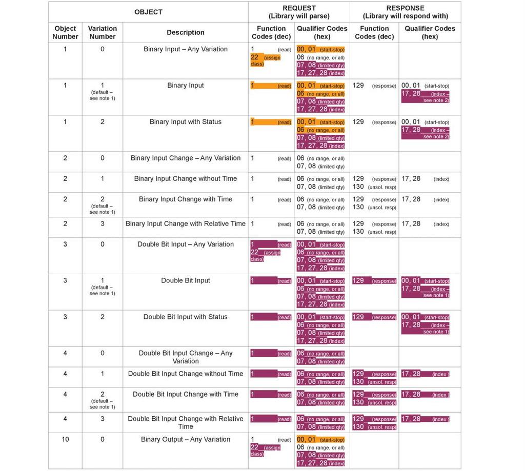
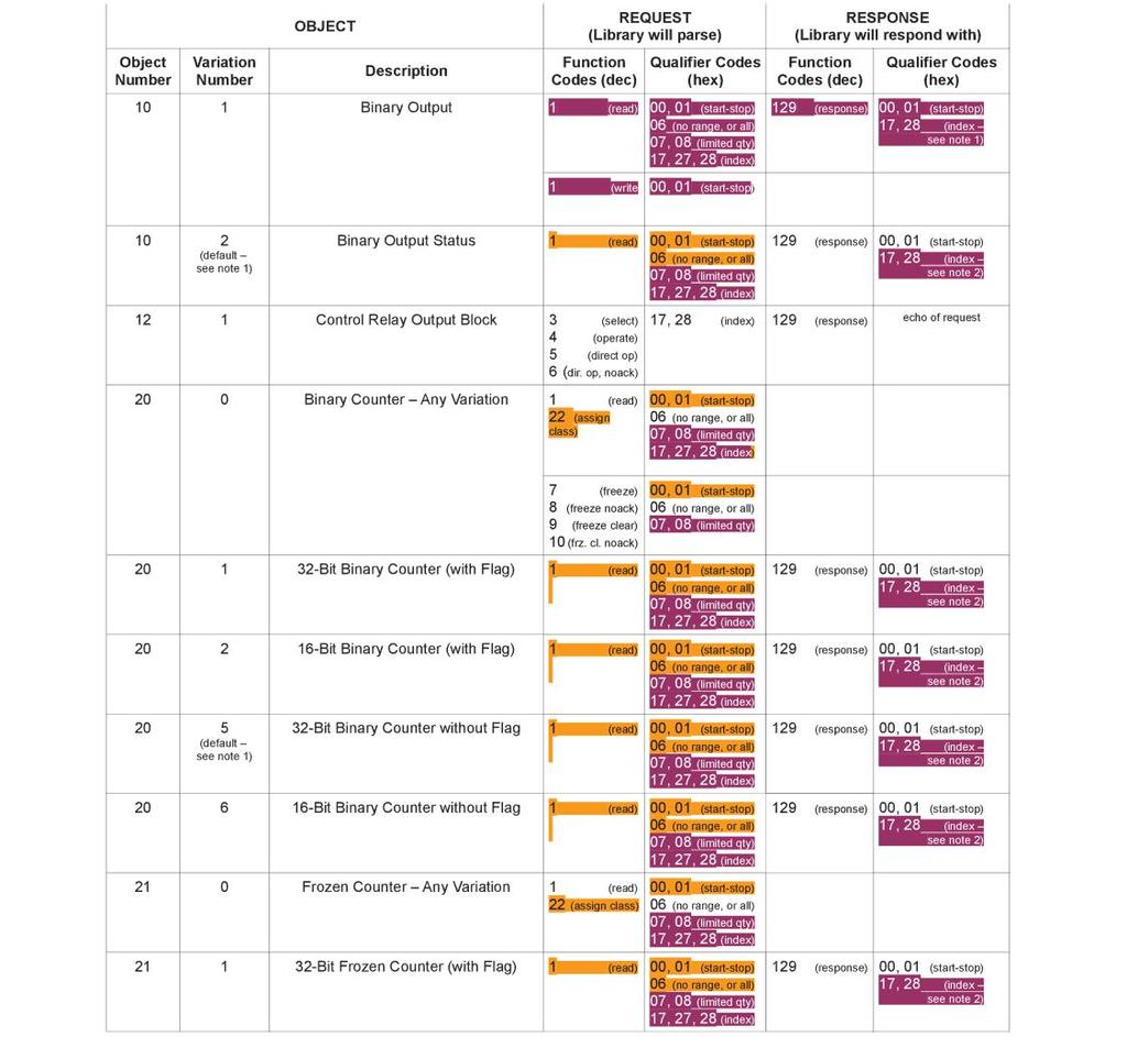
6 DNP V3.0 Point List The tables below identify all the data points provided by the implementation. Binary Input Points Static (Steady-State) Object Number: 1 Static Variation reported when variation 0 requested: 1 (Binary Input 2 without status) Point Index Name/Description AC Alarm Indicator (FAILURE=1) High Voltage Alarm Indicator (FAILURE=1) High Voltage Shutdown Alarm Indicator (FAILURE=1) Low Current Alarm Indicator (FAILURE=1) Open DC Protection Alarm Indicator (FAILURE=1) A36D ONLY. For TPSD this point will always read 0. Positive Ground Alarm Indicator (FAILURE=1). TPSD ONLY. For A36D this point will always read 0. Negative Ground Alarm Indicator (FAILURE=1). TPSD ONLY. For A36D this point will always read 0. Summary Alarm Indicator (FAILURE=1) End of Discharge Alarm Indicator (FAILURE=1). Overload Alarm Indicator (FAILURE=1) Over Temperature Alarm Enable (ENABLED=1) Over Temperature Alarm Status (FAILURE=1) Charger in Settings Menu (Set to 1 when charger is manually put into the settings menu through the front panel) Remote setting changes are disabled when this is set to 1 until the local operator exits the Settings Menu. SCADA Read Only Mode (ENABLED=1). Setting changes are not allowed when the charger is in the settings menu or when the SCADA Read Only Mode has been selected. Negative Ground Alarm Relay Contacts (CLOSED=1, OPEN=0). TPSD ONLY. High Voltage Alarm Relay Contacts (CLOSED=1, OPEN=0). Low Voltage Alarm Relay Contacts (CLOSED=1, OPEN=0). Positive Ground Alarm Relay Contacts (CLOSED=1, OPEN=0). TPSD ONLY. AC Fail Alarm Relay Contacts (CLOSED=1, OPEN=0). Summary Alarm Relay Contacts (CLOSED=1, OPEN=0). Low Current Alarm Relay Contacts (CLOSED=1, OPEN=0). Open DC Protection Alarm Relay Contacts (CLOSED=1, OPEN=0). Float/EQ Mode Indicator (FLOAT=0, EQUALIZE=1) Temperature Compensation Enable (ENABLED=1). LCD Backlight Timeout Enable (ENABLED=1) This has no effect on Chargers equipped with VFD Displays. Include Low Current Alarm in Summary Alarm (INCLUDED=1) Include AC Alarm in Summary Alarm (INCLUDED=1) Include Ground Detection Alarms in Summary Alarm (INCLUDED=1). TPSD ONLY. For A36D this point will always read 0.. Include Over Temperature Alarm in Summary (INCLUDED=1). A36D ONLY. Latch Summary Alarm (YES=1) Latch AC Fail Alarm (YES=1) Latch Low Voltage Alarm (YES=1) Latch High Voltage Alarm (YES=1)
7 Binary Input Points Static (Steady-State) Object Number: 1 Static Variation reported when variation 0 requested: 1 (Binary Input 2 without status) Point Index Name/Description Latch High Voltage Shutdown Alarm (YES=1) Latch Positive Ground Alarm (YES=1). TPSD ONLY. For A36D this point will always read 0 and writes to are prohibited. Latch Negative Ground Alarm (YES=1). TPSD ONLY. For A36D this point will always read 0 and writes to are prohibited. Latch Overload Alarm (YES=1) Latch End of Discharge Alarm (YES=1) Reset Alarms (YES=1) Ground Detection Alarm Enable. (ENABLED=1, DISABLED=0) TPSD ONLY. For A36D this point will always read 0. Test All Alarm Contacts (BEGIN TEST=1, END TEST=0). Note the HVSD alarm contacts are not tested remotely. Test Negative Ground Relay Contacts (BEGIN TEST=1, END TEST=0). TPSD ONLY. Test High Voltage Alarm Relay Contacts (BEGIN TEST=1, END TEST=0). Test Low Voltage Alarm Relay Contacts (BEGIN TEST=1, END TEST=0). Test Positive Ground Relay Contacts (BEGIN TEST=1, END TEST=0). TPSD ONLY. Test AC Alarm Relay Contacts (BEGIN TEST=1, END TEST=0). Test Summary Alarm Relay Contacts (BEGIN TEST=1, END TEST=0). Test Low Current Alarm Relay Contacts (BEGIN TEST=1, END TEST=0). Test Open DC Protection Alarm Relay Contacts (BEGIN TEST=1, END TEST=0). A36D ONLY. Binary Output Status Points Object Number: 10 Default Variation reported when variation 0 requested: 2 (Binary Output Status) Control Relay Output Blocks Object Number: 12 Point Index Name/Description Float/EQ Mode Indicator (FLOAT=0, EQUALIZE=1) Temperature Compensation Enable (ENABLED=1). LCD Backlight Timeout Enable (ENABLED=1) This has no effect on Chargers equipped with VFD Displays. Include Low Current Alarm in Summary Alarm (INCLUDED=1) Include AC Alarm in Summary Alarm (INCLUDED=1) Include Ground Detection Alarms in Summary Alarm (INCLUDED=1). TPSD ONLY. For A36D this point will always read 0 and writes to are prohibited. Include Over Temperature Alarm in Summary (INCLUDED=1) Latch Summary Alarm (YES=1) Latch AC Fail Alarm (YES=1) Latch Low Voltage Alarm (YES=1) Latch High Voltage Alarm (YES=1) Latch High Voltage Shutdown Alarm (YES=1) 7
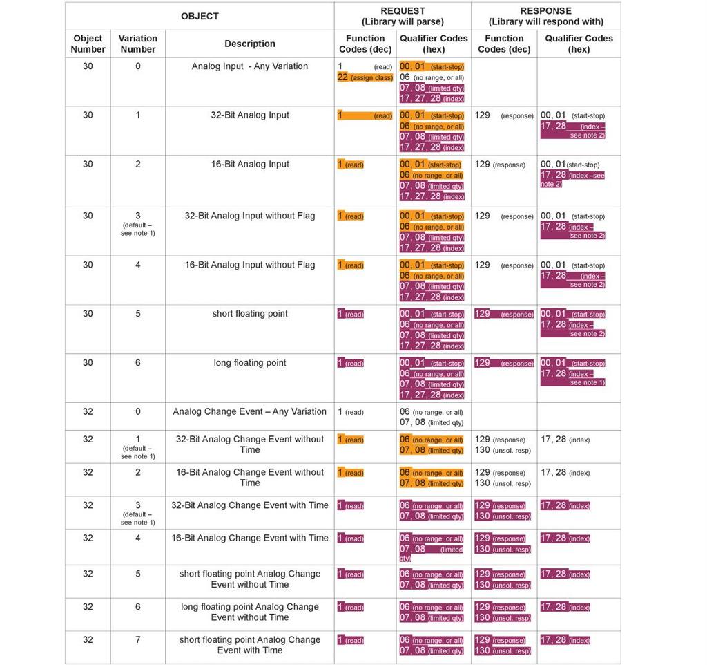
8 Binary Output Status Points Object Number: 10 Default Variation reported when variation 0 requested: 2 (Binary Output Status) Control Relay Output Blocks Object Number: 12 Point Index Name/Description Latch Positive Ground Alarm (YES=1). TPSD ONLY. For A36D this point will always read 0 and writes to are prohibited. Latch Negative Ground Alarm (YES=1). TPSD ONLY. For A36D this point will always read 0 and writes to are prohibited. Latch Overload Alarm (YES=1) Latch End of Discharge Alarm (YES=1) Reset Alarms (YES=1) Write a 1 to reset alarms. After alarms are reset software in the controller sets this point to 0. Ground Detection Alarm Enable. (ENABLED=1, DISABLED=0) TPSD ONLY. For A36D this point will always read 0 and writes to are prohibited. Test All Alarm Contacts (BEGIN TEST=1, END TEST=0). Note the HVSD alarm contacts are not tested remotely. Test Negative Ground Contacts (BEGIN TEST=1, END TEST=0). TPSD ONLY. Test High Voltage Alarm Contacts (BEGIN TEST=1, END TEST=0). Test Low Voltage Alarm Contacts (BEGIN TEST=1, END TEST=0). Test Positive Ground Contacts (BEGIN TEST=1, END TEST=0). TPSD ONLY. Test AC Alarm Contacts (BEGIN TEST=1, END TEST=0). Test Summary Alarm Contacts (BEGIN TEST=1, END TEST=0). Test Low Current Alarm Contacts (BEGIN TEST=1, END TEST=0). Test Open DC Protection Alarm Contacts (BEGIN TEST=1, END TEST=0). A36D ONLY. Analog Inputs Static (Steady-State) Object Number: 30 Static Variation reported when variation 0 requested: 4 (16-Bit Analog Input w/o Flag) Point Index Description, Units Modbus Heartbeat. This register should increment at a rate of approximately once per second. A constantly incrementing count is indicative of communications between the communications board and main controller are operating correctly. Board Number. Will read 341 for 341S card. Software Version, Version of software on 341S card. Voltage, Volts Current, Amps Equalize Cycle Time Hours Remaining, Hours, Minutes Note: The last two digits are the minutes. Auto Equalize Timer, Days Auto Equalize Timer, Hours, Minutes Note: The last two digits are the minutes. Low DC Current Alarm Low Limit, Amps. Setting the Low DC Current Alarm below this will result in disabling the Low DC Current Alarm Status Indicator. Scale Factor
9 Analog Inputs Static (Steady-State) Object Number: 30 Static Variation reported when variation 0 requested: 4 (16-Bit Analog Input w/o Flag) Point Index Description, Units Temperature Compensation Probe Reading, Degrees C Note: A shorted probe will give a reading of 273 and an open probe will give a reading of+273 Temperature Compensation Probe Status OK=0,SHORTED=1,OPEN=2,HARDWARE FAILURE=3 Maximum Settable Alarm Voltage, MAXAV, Volts Maximum Settable Alarm Current, MAXAI, Amps Over Temperature Probe Reading, Degrees C Note: A shorted probe will give a reading of 273 and an open probe will give a reading of+273 Over Temperature Probe Status OK=0,SHORTED=1,OPEN=2,HARDWARE FAILURE=3 Charger Series. (0=TPSD,1=A36D) Battery Voltage, Volts Note: This point should only be monitored when BIP15=1 NOT AVAILABLE= 30000, FAILED = Aux Temperature Probe #1, C Note: NOT AVAILABLE=30000, SHORTED=30001, OPEN=30002, FAILED=30003 Aux Temperature Probe #2, C Note: NOT AVAILABLE=30000, SHORTED=30001, OPEN=30002, FAILED=30003 Low Voltage Alarm Status (0=NO ALARM,1=LOW VOLTAGE ALARM,2=LOW BATTERY VOLTAGE ALARM) P60-407S Board Failure Alarm (0=N/A,1=NO ALARM,2=ALARM) Equalize Timer Mode (0,1 2,3,4) Equalize Timer Setting (0 to 144) Low Voltage Alarm Threshold, Volts, (0 to MAXAV) High Voltage Alarm Threshold, Volts, (0 to MAXAV) High Voltage Shutdown Alarm Threshold, Volts, (0 to MAXAV) Low DC Current Alarm Threshold, Amps, (0 to MAXAI) Low DC Current Alarm Recovery Threshold, Amps (Low DC Current Alarm Threshold to MAXAI) Low Voltage Alarm Recovery Threshold, Percent (0 to 20) Low Voltage Alarm Delay, Seconds, (1 to 300) Equalize Timer Mode 4 (Auto Equalize on LV Alarm Recovery) Delay, Seconds (1 to 255) High Voltage Alarm Delay, Seconds, (1 to 300) High Voltage Alarm Recovery Threshold, Percent (0 to 20) High Voltage Shutdown Alarm Delay, Seconds, (1 to 300) Low Current Alarm Delay, Seconds, (1 to 300) End of Discharge Alarm Threshold, Volts, (0 to MAXAV) End of Discharge Alarm Recovery Threshold, Percent (0 to 20) Overload Alarm Threshold, Amps, (0 to MAXAI) Overload Alarm Recovery Threshold, Percent (0 to 20) Scale Factor 9
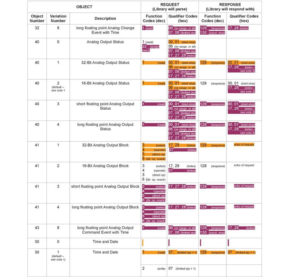
10 Analog Inputs Static (Steady-State) Object Number: 30 Static Variation reported when variation 0 requested: 4 (16-Bit Analog Input w/o Flag) Point Index Description, Units AC Alarm Delay, Seconds, (1 to 300) Ground Detection Alarm Delay, Seconds, (1-300) TPSD ONLY. For A36D this point will always read 0. Scale Factor Analog Outputs Static (Steady-State) Object Number: 40 Static Variation reported when variation 0 requested: 2 (16-Bit Analog Output Status) Point Index Description, Units, Valid Settings/Range Equalize Timer Mode (0,1 2,3,4) Equalize Timer Setting (0 to 144) Low Voltage Alarm Threshold, Volts, (0 to MAXAV) High Voltage Alarm Threshold, Volts, (0 to MAXAV) High Voltage Shutdown Alarm Threshold, Volts, (0 to MAXAV) Low DC Current Alarm Threshold, Amps, (0 to MAXAI) Low DC Current Alarm Recovery Threshold, Amps (Low DC Current Alarm Threshold to MAXAI) Low Voltage Alarm Recovery Threshold, Percent (0 to 20) Low Voltage Alarm Delay, Seconds, (1 to 300) Equalize Timer Mode 4 (Auto Equalize on LV Alarm Recovery) Delay, Seconds (1 to 300) High Voltage Alarm Delay, Seconds, (1 to 300) High Voltage Alarm Recovery Threshold, Percent (0 to 20) High Voltage Shutdown Alarm Delay, Seconds, (1 to 300) Low Current Alarm Delay, Seconds, (1 to 300) End of Discharge Alarm Threshold, Volts, (0 to MAXAV) End of Discharge Alarm Recovery Threshold, Percent (0 to 20) Overload Alarm Threshold, Amps, (0 to MAXAI) Overload Alarm Recovery Threshold, Percent (0 to 20) AC Alarm Delay, Seconds, (1 to 300) Ground Detection Alarm Delay, Seconds, (1-300) TPSD ONLY. For A36D this point will always read 0 and writes to are prohibited. End of Discharge Alarm Delay, Seconds (1-300) Overload Alarm Delay, Seconds, (1-300) Scale Factor
11 11
12 12
13 13
14 14
15 15
16 16
17 17
18 18
19 19
20 20
21 21
22 22
A36D/TPSD Modbus RTU (Serial) SCADA INTERFACE INSTRUCTIONS
 SCADA INTERFACE INSTRUCTIONS") SCADA INTERFACE INSTRUCTIONS - OPTION 21S - FOR A36D/TPSD SYSTEMS with option 500 and 550. A36D/TPSD Modbus RTU (Serial) SCADA INTERFACE OPTION 21S INSTRUCTIONS This manual is valid for A36D/TPSD Chargers
SCADA INTERFACE INSTRUCTIONS - OPTION 21S - FOR A36D/TPSD SYSTEMS with option 500 and 550. A36D/TPSD Modbus RTU (Serial) SCADA INTERFACE OPTION 21S INSTRUCTIONS This manual is valid for A36D/TPSD Chargers
A36D/TPSD Modbus TCP SCADA INTERFACE INSTRUCTIONS
 SCADA INTERFACE INSTRUCTIONS - OPTION 21Q - FOR A36D/TPSD SYSTEMS with 500 and 550 option. A36D/TPSD Modbus TCP SCADA INTERFACE OPTION 21Q INSTRUCTIONS This manual is valid for A36D/TPSD Chargers equipped
A77 SNMPv1 SCADA INTERFACE INSTRUCTIONS
 A77 SNMPv1 SCADA INTERFACE OPTION 21X INSTRUCTIONS This manual is only valid for A77 Chargers equipped with the following: S2A-368S card with software version P368S0111 080116 MIB file P389S-21X4-00 S2A-389S
La Marche Manufacturing Company Option 46 Series. Digital Combined Accessory Package. Installation and Operation Manual
 La Marche Manufacturing Company www.lamarchemfg.com Option 46 Series Digital Combined Accessory Package Installation and Operation Manual This manual is subject to change without notice. You may obtain
A77 SNMPv3 SCADA INTERFACE INSTRUCTIONS
 A77 SNMPv3 SCADA INTERFACE OPTION 21X INSTRUCTIONS This manual is only valid for A77 Chargers equipped with the following: S2A-368S card with software version P368S0112 MIB file P389S-21X4-01-P368S0112
La Marche Manufacturing Company Option 16 Series. Digital Combined Accessory Package. Installation and Operation Manual
 La Marche Manufacturing Company www.lamarchemfg.com Option 16 Series Digital Combined Accessory Package Installation and Operation Manual This manual is subject to change without notice. You may obtain
TPSD. Installation and Operation Manual. Filtered Battery Charger Power Supply / Battery Eliminator
 La Marche Manufacturing Company www.lamarchemfg.com TPSD Filtered Battery Charger Power Supply / Battery Eliminator Installation and Operation Manual 106 Bradrock Dr. Des Plaines 60018-1967 Tel: 847 299
La Marche Manufacturing Company A36D. Battery Charger / Power Supply. Installation and Operation Manual
 La Marche Manufacturing Company www.lamarchemfg.com A36D Battery Charger / Power Supply Installation and Operation Manual 106 Bradrock Dr. Des Plaines, IL 60018-1967 Tel: 847 299 1188 Fax: 847 299 3061
Modbus RTU RS485 Manual
 Modbus RTU RS485 Manual AUTOMATED FUEL MAINTENANCE SYSTEMS FTI-5A, FTI-10A, FTI-20A FUEL TECHNOLOGIES INTERNATIONAL 06/10/2014 Rev B - Fuel Technologies - Modbus The Modbus Communications Setup Button
Carbon Monoxide Transmitter
 Introduction The CO Transmitter uses an electrochemical sensor to monitor the carbon monoxide level and outputs a field-selectable 4-20 ma or voltage signal. The voltage signal may also be set to 0-5 or
EOS INTERFACE GUIDE AND POINTS LIST For EOS BTCII Firmware Version J1239D-570 and newer
 Installation and interface must be performed by a qualified controls technician. IMPORTANT: THIS MANUAL CONTAINS INFORMATION REQUIRED FOR INSTALLATION, INTERFACE AND CONFIGURATION OF THIS EQUIPMENT. READ
MO n : 12JMC rév A
 CTT8 MO n : rév A Page 2 / 18 MODIFICATIONS Rev. Description Date Checked by Approuved by Z Creation 2012/02/12 JMC LA A First issue 2012/02/14 JMC LA INDEX Page 3 / 18 GENERALITY 4 INTRODUCTION 4 ACCESSORIES
UNC100 Integra Manual
 UNC100 Integra Manual New Generation Building Security July 30, 2014 V1.2 Copyright Notice Copyright 1995-2014 by All rights reserved Worldwide. Printed in Canada. This publication has been provided pursuant
ENGINE MONITOR VOTT MODEL: YEAR WARRANTY
 INSTRUCTION MANUAL ENGINE MONITOR VOTT MODEL: 023-4400-0 3 YEAR WARRANTY INTRODUCTION The VOTT meter is an ideal engine monitor, which displays data via the J1939 CAN Bus. The meter utilizes a large LCD
CTT8 TEMPERATURE MONITOR DEVICE
 INSTRUCTION MANUAL IM302-U v2.3 CTT8 TEMPERATURE MONITOR DEVICE GENERALITY The device of control temperatures CTT8 is used in the control of electric machine, transformer, motor, etc. where it s possible
NGC-UIT2 MODBUS PROTOCOL INTERFACE MAPPING FOR NGC-30 SYSTEMS. Firmware versions up to V2.0.X
 NGC-UIT2 MODBUS PROTOCOL INTERFACE MAPPING FOR NGC-30 SYSTEMS Firmware versions up to V2.0.X INDUSTRIAL HEAT TRACING SOLUTIONS EN-RaychemNGCUIT2Protocol-IM-H57880 06/15 1/32 Contents Section I Introduction
Q-SMART MODBUS KIT. Modbus Protocol & Parameters. Cod EN rev.a ed.08/2018. Q-SMART Software Version AE17
 Q-SMART MODBUS KIT Modbus Protocol & Parameters Cod.001085120EN rev.a ed.08/2018 Q-SMART Software Version AE17 Index 1 Modbus Protocol on Q-SMART... 4 1.1 Broadcasting... 4 1.2 Data Protection... 4 1.3
Lift Station Level Controller
 Lift Station Level Controller Installation and Operation Manual 1 California Motor Controls, Inc. Benicia, CA Table of Contents 1. Features Product Overview... 4-6 Access Security... 7 Optional Features...
PowerLogic ION Setup Meter Configuration Software Configuration Guide
 PowerLogic ION Setup Meter Configuration Software Configuration Guide 70002-0293-03 12/2010 Conventions Used in this Manual This section describes the symbols and terminology used in this guide. Symbols
F Technical Bulletin SC 370 SMART Modbus Interface
 F7904502 Document Revision History Document Versiosion Modbus Map Ver- Date Author Notes 1 10 9/26/17 JGG Document Created Flash Technology, 332 Nichol Mill Lane, Franklin, TN 37067 www.flashtechnology.com
A77 Series. Microprocessor Controlled SCR Filtered/Battery Eliminator Filtered Charger. Installation and Operation Manual
 La Marche Manufacturing Company www.lamarchemfg.com A77 Series Microprocessor Controlled SCR Filtered/Battery Eliminator Filtered Charger Installation and Operation Manual This manual is subject to change
Millennium Xtra. Millennium ATMA setup and configuration guide. May Millennium Group, Inc.
 Millennium Xtra Millennium ATMA setup and configuration guide May 16 2017 Millennium Group, Inc. 16 Tech Circle Natick, MA 01760 P: 508-655-1340 F: 508-651-2902 Millennium ATMA setup and configuration
TEMON 4-C. Doc. N MO-0368-ING TEMPERATURE MONITOR DEVICE TYPE TEMON 4-C OPERATION MANUAL. Microener- Copyright 2010 FW 2.1 Date Rev.
 TEMPERATURE MONITOR DEVICE TYPE TEMON 4-C OPERATION MANUAL Microener- Copyright 2010 FW 2.1 Date 01.12.2008 Rev. 0 1. Generality 3 2. Introduction 3 3. Accessories and Options 3 4. Installation 3 5. Connection
ibox Modbus Server Gateway for the integration of Notifier ID3000 / ID3002 / ID60 / ID50 fire panels in Modbus enabled monitoring and control systems
 Honeywell Life Safety Iberia C/Pau Vila 15-19; 08911 Badalona Barcelona T. 902 03 05 45; Internacional:+34932424236 www.honeywelllifesafety.es infohlsiberia@honeywell.com ibox Modbus Server Gateway for
FieldServer Driver - Serial FS Notifier NCA
 Driver Version: 1.00 Document Revision: 15 Description FieldServer Driver - Serial FS-8700-98 Notifier NCA The NCA (Network Control Annunciator) Serial driver allows the FieldServer to record data from
HRX Technical Manual. Version 1.2
 HRX 5000 Technical Manual Version 1.2 Contents: Specification...2 Connectors...5 RS-485 Network Connectors (J6 and J7)...5 RS-232 to Printer (J19)...6 RS-232 to PC (J8)...7 TCP/IP...8 Power (J21)...9 Fire
DC VOLTMETER DCV-10 / 10A / 10C / 10S / 10CS / 11 / 11A / 11C / 11S / 11CS. A4741 / Rev.1
 DC VOLTMETER DCV-10 / 10A / 10C / 10S / 10CS / 11 / 11A / 11C / 11S / 11CS User Manual and Menu Map A4741 / Rev.1 www.entes.com.tr ATTENTION -Disconnect all power before connecting the device. -Don t remove
Two-Channel Gas Controller
 Two-Channel Gas Controller Specifications subject to change without notice. USA 09 Page of DESCRIPTION Highly configurable, UL 0 performance-tested and -certified, and wall-mounted gas monitor; continuously
ModSync Sequencing System Installation & Operation Manual. For use with Fulton Steam Boilers.
 ModSync Sequencing System Installation & Operation Manual For use with Fulton Steam Boilers. Revision 3.0 8/21/2008 - 2 - Table of Contents Introduction Page 4 Features Page 4 Sequence of Operation Page
NGC-40 Bridge. Modbus Overview. Raychem-AR-H58862-NGC40BridgeModbusOV-EN-1805 nvent.com 1
 NGC-40 Bridge Overview Raychem-AR-H58862-NGC40BridgeOV-EN-1805 nvent.com 1 Table of Contents 1. NGC-40 Overview... 9 1.1 Example NGC-40 System... 10 2. Legal stuff... 11 3. Protocols... 12 3.1 Data es...
RS485 MODBUS Module 8AI
 Version 1.4 15/04/2013 Manufactured for Thank you for choosing our product. This manual will help you with proper support and proper operation of the device. The information contained in this manual have
DPR-145 TEMPERATURE PROTECTION RELAY. DPR-145 User Manual V-2.0 ( ) PT100 INPUTS: 4 RELAY OUTPUTS: 4 RS-485 MODBUS PORT VDC SUPPLY -1-
 PT100 INPUTS: 4 RELAY OUTPUTS: 4 RS-485 MODBUS PORT VDC SUPPLY -1-") DPR-45 User Manual V-2.0 (2..206) DPR-45 TEMPERATURE PROTECTION RELAY PT00 INPUTS: 4 RELAY OUTPUTS: 4 RS-485 MODBUS PORT 9-50VDC SUPPLY DESCRIPTION DPR-45 is a precision unit designed for the temperature
DPR-45 User Manual V-2.0 (2..206) DPR-45 TEMPERATURE PROTECTION RELAY PT00 INPUTS: 4 RELAY OUTPUTS: 4 RS-485 MODBUS PORT 9-50VDC SUPPLY DESCRIPTION DPR-45 is a precision unit designed for the temperature
Endura AZ40 Oxygen and carbon monoxide equivalent (COe) analyzer
 analyzer") ABB MEASUREMENT & ANALYTICS OPERATING INSTRUCTION SUPPLEMENT COM/AZ40/MOD-EN REV. A Endura AZ40 Oxygen and carbon monoxide equivalent (COe) analyzer Communications supplement Measurement made easy Oxygen
ABB MEASUREMENT & ANALYTICS OPERATING INSTRUCTION SUPPLEMENT COM/AZ40/MOD-EN REV. A Endura AZ40 Oxygen and carbon monoxide equivalent (COe) analyzer Communications supplement Measurement made easy Oxygen
READ AND SAVE THESE INSTRUCTIONS
 XXXXXXX-0 EN 1904 READ AND SAVE THESE INSTRUCTIONS BASIC-PLC CONTROLLER MANUAL For all Condair desiccant dryer with equipped with Basic- PLC valid from version: PLC-35/PLC-45 18.04.03 Dehumidification
OPERATOR INSTRUCTIONS FOR DM3000
 OPERATOR INSTRUCTIONS FOR DM3000 American Power Conversion 132 Fairgrounds Road West Kingston, RI 02892 USA Tel: 1-800-788-2208 Web: www.apc.com American Power Conversion, Ballybrit Industrial Estate,
MYRIAD TRIPLEX PUMP CONTROLLER INSTRUCTION MANUAL
 MYRIAD TRIPLEX PUMP CONTROLLER INSTRUCTION MANUAL MYRIAD TPC VISIT OUR WEBSITE SIGMACONTROLS.COM MYRIADI&O062705 2 TABLE OF CONTENTS INTRODUCTION 3 Ordering Information Specifications Features WIRING 7,8
Temperature Controllers
 Model TEC-4100 1/4 DIN Model TEC-4100 1/4 DIN Temperature Controller Ordering Code: Power Input BOX 1 4 = 90-250 VAC 5 = 11-26 VAC / VDC TEC-4100- Configurable for 4 Programmable Outputs and NEMA 4X/IP65
2) This manual covers Fire and General Alarm systems. The differences are described in the appropriate sections.
 This manual covers Fire and General Alarm systems. The differences are described in the appropriate sections.") ISSUES ISSUE DATE RELEASED DETAILS OF CHANGE AUTHOR 4 Rev 2 September 2004 Changes for 4000 series. DB 4 Rev 3 April 2005 Screen shots updated and other minor changes K.Z. 4 Rev 4 September 2006 4 Rev
ISSUES ISSUE DATE RELEASED DETAILS OF CHANGE AUTHOR 4 Rev 2 September 2004 Changes for 4000 series. DB 4 Rev 3 April 2005 Screen shots updated and other minor changes K.Z. 4 Rev 4 September 2006 4 Rev
PROCESS & TEMPERATURE UNIVERSAL INPUT DIGITAL METERS
 PROCESS & TEMPERATURE UNIVERSAL INPUT DIGITAL METERS NOVA PD56 Series Thermocouple, RTD, & Process Inputs Universal Power Supply 1-24 VAC Up to 3 Alarm Relays Retransmitting 4-2 ma Output Input Max/Min
FCD-wire Contents. List of Figures
 FCD-wire Contents FCD-X21 Configuration 1 Introduction... 1 2 Opening the FCD Application... 1 3 FCD Window... 2 4 FCD LEDs... 3 5 Configuration Operations... 4 FCD Info...4 FCD System Info...5 FCD Interface
Refrigeration Controller Operator s Manual (HRC) PO Box 6183 Kennewick, WA
 PO Box 6183 Kennewick, WA") Refrigeration Controller Operator s Manual (HRC) PO Box 6183 Kennewick, WA 99336 www.jmcvr.com 1-509-586-9893 Table of Contents TABLE OF FIGURES...1 OVERVIEW OF THE HRC CAPABILITIES...2 INSTALLATION AND
Refrigeration Controller Operator s Manual (HRC) PO Box 6183 Kennewick, WA 99336 www.jmcvr.com 1-509-586-9893 Table of Contents TABLE OF FIGURES...1 OVERVIEW OF THE HRC CAPABILITIES...2 INSTALLATION AND
Process & TeMPerATUre UniversAl input DigiTAl MeTers
 Process & TeMPerATUre UniversAl input DigiTAl MeTers nova PD56 series Thermocouple, rtd, & Process inputs Universal Power supply 1-24 va c Up to 3 Alarm relays retransmitting 4-2 ma output input Max/Min
P2267 NETWORK INTERFACE
 P2267 NETWORK INTERFACE USER MANUAL FOR OPERATING SYSTEMS: 22031-03 23636-01 October 2009 Associated Controls (Australia) Pty. Limited 2-4 Norfolk Road Greenacre, NSW, 2190. PH +61 2 9642 4922, FAX +61
NGC-40 PANEL MOUNTED ADVANCED MODULAR HEAT-TRACING CONTROL SYSTEM HTC HTC3
 NGC-40 PANEL MOUNTED ADVANCED MODULAR HEAT-TRACING CONTROL SYSTEM Local configuration and monitoring with Raychem Touch 1500 touch screen display PRODUCT OVERVIEW The Raychem NGC-40 is a multipoint electronic
Model A2100 Series Annunciator
 Seekirk Model A2100 Series Annunciator Applications: For usage within transformers, switchgear, breakers and/or within any processing equipment or control room applications either attended or unattended
MAIN MENU/HOME SCREEN OVERVIEW
 s Sensor (S11) 3038 µs/cm 77.1 F Generic AI (S21) 30.5% Generic AI (S22) 37.9% List of possible s: Contacting Conductivity Electrodeless Conductivity Temperature ph ORP Disinfection Generic Transmitter/AI
Metasys Integrator Vilter Application
 Metasys Connectivity Technical Manual 629.5 Metasys Integrator Section Application Note Issue Date 1294 APPLICATION NOTE Metasys Integrator Vilter Application lntroduction Page 3 Application Details *3
TECHNICAL MANUAL CVM 20 C 5005 CV/04-99 GB
 Summary 1 CONNECTIONS... 3 1.1 TEMPERATURE PROBES...3 1.2 LOW VOLTAGE DIGITAL INPUTS...3 1.3 LIVE DIGITAL INPUTS...4 1.4 RELAY OUTPUTS...5 2 POWER SUPPLY... 6 3 SERIAL CONNECTIONS... 6 4 SOFTWARE... 7
QS941A Controller User Interface
 Product Manual Select Code 167-792-184 Comcode CC848816612 Issue 3 November 2009 Notice: The information, specifications, and procedures in this manual are subject to change without notice. Lineage Power
SEQUENCE OF OPERATIONS
 SEQUENCE OF OPERATIONS DDC CONTROLLER: Controller with integral LCD readout for changing set points and monitoring unit operation. Provided with required sensors and programming. Factory programmed, mounted,
System 57. An advanced world of intelligent gas detection system management
 An advanced world of intelligent gas detection system management A world of control technology High precision, intelligent control Master/voted alarm options High packing density Flexible I/O configuration
Manual for the integration in BMS/GTC
 Manual for the integration in BMS/GTC Communication parameters MODBUS RTU and BACNET COMMUNICATION UTBS PRO-REG Software Version 3.6 EN ÍNDEX 1. GENERALITIES...2 1.1. Introduction...2 1.2. signals types...2
DEEP SEA ELECTRONICS PLC DSE94xx Battery Charger Series Configuration Suite PC Software Manual
 DEEP SEA ELECTRONICS PLC DSE94xx Battery Charger Series Configuration Suite PC Software Manual Document Number: 057-159 Author: Fady Atallah DSE94xx Configuration Suite PC Software Manual ISSUE 15 DSE94xx
Application, Installation, Operation & Maintenance Manual
 APPROVED BY:JBJ PRESCIENT III FIRE ALARM & GAS EXTINGUISHING CONTROL PANEL Application, Installation, Operation & Maintenance Manual PAGE 1 of 43 CONTENTS 1. INTRODUCTION... 3 2. GENERAL DESCRIPTION...
CONTROL PANEL INTERFACE ACTIVATE THE GENERATOR DISPLAY INTERFACE MENUS. Control Panel USING THE AUTO/OFF/MANUAL SWITCH
 CONTROL PANEL INTERFACE USING THE AUTO/OFF/MANUAL SWITCH With the switch set to AUTO, the engine may crank and start at any time without warning. Such automatic starting occurs when utility power source
1.1 Remote Annunciator Controller (RAC) and 1 Switch (ATC-600/800) via Modbus TCP/IP Ethernet Gateway
 and 1 Switch (ATC-600/800) via Modbus TCP/IP Ethernet Gateway") Remote Annunciator Controller (RAC) Instruction Sheet for Automatic Transfer Switches (ATS) Revision:01 IB01602088E 1.1 Remote Annunciator Controller (RAC) and 1 Switch (ATC-600/800) via Modbus TCP/IP
Remote Annunciator Controller (RAC) Instruction Sheet for Automatic Transfer Switches (ATS) Revision:01 IB01602088E 1.1 Remote Annunciator Controller (RAC) and 1 Switch (ATC-600/800) via Modbus TCP/IP
NetSure. ACU+ Controller (Advanced Control Unit Plus) User Manual (UM1M820BNA), Revision R
 User Manual (UM1M820BNA), Revision R") NetSure ACU+ Controller (Advanced Control Unit Plus) User Manual (UM1M820BNA), Revision R Specification Number: 1M820BNA, 1M820DNA Model Number: M820B, M820D The information contained in this document
NetSure ACU+ Controller (Advanced Control Unit Plus) User Manual (UM1M820BNA), Revision R Specification Number: 1M820BNA, 1M820DNA Model Number: M820B, M820D The information contained in this document
INSTALLATION INSTRUCTIONS
 INSTALLATION INSTRUCTIONS Modbus Supplemental Manual for LC6000 Controller The LC6000 is capable of being remotely monitored through the integrated Ethernet port. Through this port the controller will
Model A1700 Series Annunciator
 Seekirk Model A1700 Series Annunciator Applications: For usage in all types of process industries, electric generation, transmission and distribution, gas and water utilities. Features: The Seekirk model
FIRERAY 5000 range USER GUIDE
 FIRERAY 5000 range USER GUIDE 0044-003-04 IMPORTANT PLEASE NOTE: The beam path MUST be kept clear of obstructions at all times! Failure to comply may result in the Detector initiating a Fire or Fault signal.
EXPERT TRI-STAR. Temperature controller. User s Manual
 Temperature controller r s Manual WARNINGS The warranty can be void if this product is used in a manner not specified by the manufacturer. Every effort has been made to ensure that this manual is complete,
FieldServer Driver - Serial FS SBT-FSI (Siemens Building Technologies Foreign Systems Interface)
") Driver Version: 1.06 Document Revision: 4 Description FieldServer Driver - Serial FS-8700-40 SBT-FSI (Siemens Building Technologies Foreign Systems Interface) This FieldServer driver can be used to poll
Driver Version: 1.06 Document Revision: 4 Description FieldServer Driver - Serial FS-8700-40 SBT-FSI (Siemens Building Technologies Foreign Systems Interface) This FieldServer driver can be used to poll
LMS-188-4P-BMS 4 POINT DIGITAL MONITOR/ALARM WITH PROTOCOL CONVERTER OPERATING INSTRUCTIONS
 G LMS 188 4P BMS August, 2018 LMS-188-4P-BMS 4 POINT DIGITAL MONITOR/ALARM WITH PROTOCOL CONVERTER OPERATING INSTRUCTIONS! WARNING: This product can expose you to chemicals including lead, which is known
MODEL P531, P532 AND P532UI FLAME MONITOR OPERATING MANUAL
 MODEL P531, P532 AND P532UI FLAME MONITOR OPERATING MANUAL TABLE OF CONTENTS DESIGN FEATURES OVERVIEW... 1 Viewing Head Selection...1 USER INTERFACE OVERVIEW... 1 Default Settings...2 Numerical configuration...2
FlameGard 5 MSIR HART
 FlameGard 5 MSIR HART Multi-Spectral Infrared Flame Detector HART Communication with the FlameGard 5 Multi-spectral Infrared Detector The information and technical data disclosed in this document may be
Replaceable LED modules. Sleep or unattended mode. Auto-silence and auto-acknowledge
 Replaceable LED modules 11 Alarm Sequences as per ISA-18.1 standard Each channel/window fully field programmable RS232 or RS485 MODBUS-RTU communication Repeat relay for each window and multifunction relays
System 57. An advanced World of intelligent gas detection system management
 An advanced World of intelligent gas detection system management A World of control technology High precision, intelligent control Master / voted alarm options High packing density Flexible I/O configuration
Fire Burglary Instruments Inc. XL-2G Gold Control/Communicator Installation Training Seminar Rev. 5/96
 Fire Burglary Instruments Inc. XL-2G Gold Control/Communicator Installation Training Seminar Rev. 5/96 XL-2G Gold Product Overview 7 Zones (6 programmable + panic or keyswitch zone) Fast Loop Response
1.1 Ethernet Remote Annunciator Controller (RAC) using the up to 4 ATC-300+ connected via RS-485 to TCP/IP gateway
 using the up to 4 ATC-300+ connected via RS-485 to TCP/IP gateway") Ethernet Remote Annunciator Controller (RAC) Instruction Sheet for Automatic Transfer Switches (4 x ATS) Revision: 01 IB01602082E 1.1 Ethernet Remote Annunciator Controller (RAC) using the up to 4 ATC-300+
Ethernet Remote Annunciator Controller (RAC) Instruction Sheet for Automatic Transfer Switches (4 x ATS) Revision: 01 IB01602082E 1.1 Ethernet Remote Annunciator Controller (RAC) using the up to 4 ATC-300+
FL500 Modbus Communication Operating Manual. Order No.: /00. MSAsafety.com
 FL500 Modbus Communication Operating Manual Order No.: 10193214/00 MSAsafety.com 1000 Cranberry Woods Drive Cranberry Township, PA 16066 A Phone 1-800-MSA-2222 Fax 1-800-967-0398 For your local MSA contacts
ModBus DE-1 INSTALLATION AND USER MANUAL
 ModBus DE-1 INSTALLATION AND USER MANUAL INTESIS Software, SL Distributed by DURAN ELECTRONICA S.L Tomás Bretón 50 28045 MADRID, España duran@duranelectronica.com www.duranelectronica.com 2 2010 DURAN
CONsOlIDATOR 4 & 8. MulTI- C h ANNEl CONTROllERs. ConsoliDator 4 Model PD940 ConsoliDator 4 Features. ConsoliDator 8 Features.
 CONsOlIDATOR 4 & 8 MulTI- C h ANNEl CONTROllERs ConsoliDator 4 Model PD940 ConsoliDator 4 Features Four 4-20 Four 4-20 Outputs ConsoliDator 8 Features Eight 4-20 Two 4-20 Outputs Common Features Four Pulse
Product Manual SZ1145
 Product Manual SZ114 General Purpose Monitor Communicating Controls Description The SZ114 is a microprocessor-based monitoring and alarm interface designed to monitor up to four 1000 Ω platinum temperature
BMS MU Internet Ready 24 Volt Battery Management System With Built-in Remote Monitoring and Control. Owners Guide
 BMS-360-24-MU Internet Ready 24 Volt Battery Management System With Built-in Remote Monitoring and Control. Owners Guide (These instructions are intended for use by a technician familiar with electronic
R E C T I F I E R I N V E R T E R C O N V E R T E R SB7
 SCR Battery Charger Product Specifications Description The is RIC Electronics premiere SCR battery charger/rectifier. The provides power to critical DC loads through a wide range of outputs and is engineered
End To End Optical Beam Smoke Detector. Additional Information
 End To End Optical Beam Smoke Detector Additional Information EN 1. Multiple Zone Wiring When using more than one System Controller on a single zone of a conventional Fire Control Panel (FCP), it is important
USER MANUAL FOR OPERATING SYSTEM
 P2262 ALARM PANEL USER MANUAL FOR OPERATING SYSTEM 21765-07 September 1999 Associated Controls (Aust) PTY. LTD. 29 Smith Street, Hillsdale, NSW, 2036. PH (02) 9311 3255, FAX (02) 9311 3779 Page 1 of 177
Diagnostics and Monitoring System WEB Tool 2. User Manual
 Diagnostics and Monitoring System 2 (Translation of the original documentation) User Manual S/N: Valid from: 01.05.2012 Rev.: 2.0 2 Rev. 1.... 1 1.1 General information... 1 1.1.1 Equipment... 1 1.1.2
INSTALLATION AND OPERATING MANUAL
 INSTALLATION AND OPERATING MANUAL Spectron Gas Control Systems GmbH Fritz-Klatte-Str. 8 65933 Frankfurt Germany Tel.: +49 69 38016-0 Fax: +49 69 38016-200 info@spectron.de www.spectron.de is a unit that
VE.NET GMDSS PANEL USER MANUAL INSTALLATION MANUAL
 VE.NET GMDSS PANEL USER MANUAL INSTALLATION MANUAL Copyrights 2007 Victron Energy B.V. All Rights Reserved This publication or parts thereof, may not be reproduced in any form, by any method, for any purpose.
COMMANDER 150. User Guide Universal Process Indicator A1
 COMMANDER 150 User Guide Universal Process Indicator COMMANDER 150 888888A1 A2 A3 Use of Instructions Warning. An instruction that draws attention to the risk of injury or death. Caution. An instruction
IRIS Touch 400 & 600 Range Installation Manual. Honeywell Galaxy Range. Version 2.0
 IRIS Touch 400 & 600 Range Installation Manual Honeywell Galaxy Range Version 2.0 Table of Contents 1 System Overview... 4 2 IRIS Touch 440 & 640 PCB Layout... 5 3 Connection & Configuration for Honeywell
20 Light Remote Annunciator
 Light Remote Annunciator Owner s Manual Surface Mount Flush Mount 94-95- Standard Annunciator 94-, 94-95-, 95-4- 4- Annunciator w/remote Relay Panel 4-, 4-4-, 4-49-, 49-49-, 49- Time Multiplexed Annunciator
Metasys Integrator Airflow Application
 Metasys Connectivity Technical Manual 69. Metasys Integrator Section Application Note Issue Date 0998 APPLICATION NOTE Metasys Integrator Airflow Application lntroduction Page Application Details * Component
NGC-40 PANEL MOUNTED ADVANCED MODULAR HEAT-TRACING CONTROL SYSTEM HTC HTC3 PRODUCT OVERVIEW
 NGC-40 PANEL MOUNTED ADVANCED MODULAR HEAT-TRACING CONTROL SYSTEM Local configuration and monitoring with Raychem Touch 1500 touch screen display PRODUCT OVERVIEW The nvent RAYCHEM NGC-40 is a multipoint
Poolsmart Plus Touchscreen Heating Controller. Installation & Operating Manual
 Poolsmart Plus Touchscreen Heating Controller Installation & Operating Manual Important Notes Congratulations on purchasing the PoolSmart Plus touchscreen heating controller, manufactured in England to
1600 Gas Controller. User s Manual. Industrial Scientific Corporation. Version 3.2 September 1, 2006
 1600 Gas Controller User s Manual Version 3.2 September 1, 2006 Industrial Scientific Corporation 1 INTRODUCTION... 1 1.1 GENERAL OPERATION... 1 1.1.1 Power Up... 1 1.1.2 Viewing Sensors... 2 1.1.3 Acknowledging
Networked Access Control Panel. Installation Guide
 XP2M Networked Access Control Panel V1.0X Installation Guide X P 2 M A C C E S S C O N T R O L S Y S T E M Installation Guide Document Ref: PLAN XP2M Installation Guide V4(G)2010 Access Control Services
INSTRUCTION MANUAL and DETAILED PRODUCT SPECIFICATION TRIPLEX PUMP CONTROL SYSTEM MODEL NUMBER CPC-3. M336 Rev F. November 21, 2000.
 INSTRUCTION MANUAL and DETAILED PRODUCT SPECIFICATION TRIPLEX PUMP CONTROL SYSTEM MODEL NUMBER CPC-3 M336 Rev F November 21, 2000 ÇConsilium Consilium US, Inc. 59 Porter Rd Littleton, MA 01460-1431 USA
LMHF. Software Manual
 INSTALLATION, OPERATING AND TROUBLESHOOTING INSTRUCTIONS FOR LMHF SOFTWARE LMHF Software Manual CPN 123907 ECN/DATE ISSUE DATE: ECN 19364-12/11 106 BRADROCK DRIVE DES PLAINES, IL. 60018-1967 (847) 299-1188
BMS MU Internet Ready Battery Management System Owners Guide
 BMS-1000-12-MU Internet Ready Battery Management System Owners Guide (These instructions are intended for use by a technician familiar with electronic products) Built-in Active Power Factor Correction
How to use the BTRM in Remote Enclosures
 How to use the BTRM in Remote Enclosures Part Number: BTRM-200 Product Release Date: April 01, 2013 Software version: BTRM2_2013-05-06_2316_DNPV2V130D The Ventev Battery Test Remote Monitor (BTRM) has
SUB-STATION ANNUNCIATOR INSTRUCTION MANUAL
 SUB-STATION ANNUNCIATOR INSTRUCTION MANUAL Page 1 of 76 The following methods are used in this manual to alert the user to important information:- WARNING! Warnings are provided for operator safety and
OWNERS MANUAL YEAR LIMITED WARRANTY READ ALL INSTRUCTIONS BEFORE PROCEEDING. Store this booklet for future reference
 5100 Premier Series 7-Day Programmable 2-Heat / 2-Cool Heat /Cool Digital Thermostat OWNERS MANUAL Compatible with low voltage multi-stage heat / cool systems with up to two stages of heating and two stages
Refrigerated air dryers
 Refrigerated air dryers OPERATING AND MAINTENANCE MANUAL Original instructions 38178800319 OPERATING AND MAINTENANCE MANUAL - Contents 1 CONTENTS CONTENTS... 1 Chapter 1 IDRY ELECTRONIC CONTROLLER...
Product Manual SZ1144
 Product Manual SZ1144 Refrigeration Temperature Monitor Communicating Controls Description The SZ1144 is a microprocessor-based monitoring and alarm interface designed to monitor up to four 1000 Ω platinum
OVEN INDUSTRIES, INC.
 OVEN INDUSTRIES, INC. OPERATING MANUAL Model 5C7-252 TEMPERATURE CONTROLLER With PLC Inputs Introduction Thank you for purchasing our controller. The Model 5C7-252 is an exceptionally versatile unit and
T M. User Manual. MarinaGuard. Ground Fault Monitoring Panel For Marina Shore Power
 T M User Manual MarinaGuard Ground Fault Monitoring Panel For Marina Shore Power NAE1095810 / 03.2013 T M Bender Inc. USA: 700 Fox Chase Coatesville, PA 19320 Toll-Free: 800-356-4266 Phone: 610-383-9200
PowerWizard. Level 1.0 & Level 2.0 Control Systems Training
 PowerWizard Level 1.0 & Level 2.0 Control Systems Training New Systems Current Systems Systems Comparison Level 1 Level 2 Level 3 Level 4 PowerWizard Level 3.0 PowerWizard Level 4.0 Overview Common parts
MF-PFA ver 3.x. Micaflex PFA ver 3. Pressure- and Flow transmitter with alarmfunction. Installation- & Operation manual [Dok. id: mi-303gb_180528]
![MF-PFA ver 3.x. Micaflex PFA ver 3. Pressure- and Flow transmitter with alarmfunction. Installation- & Operation manual [Dok. id: mi-303gb_180528]](/thumbs/95/126098054.jpg "MF-PFA ver 3.x. Micaflex PFA ver 3. Pressure- and Flow transmitter with alarmfunction. Installation- & Operation manual [Dok. id: mi-303gb_180528]") Installation- & Operation manual [Dok. id: mi-303gb_180528] Micaflex PFA ver 3. Pressure- and Flow transmitter with alarmfunction and control output MF-PFA ver 3.x NOTE! Read through the entire manual
Installation- & Operation manual [Dok. id: mi-303gb_180528] Micaflex PFA ver 3. Pressure- and Flow transmitter with alarmfunction and control output MF-PFA ver 3.x NOTE! Read through the entire manual