Fridge-tag 2 L. with external sensor OPERATION MANUAL
|
|
|
- Jeffery McCoy
- 6 years ago
- Views:
Transcription
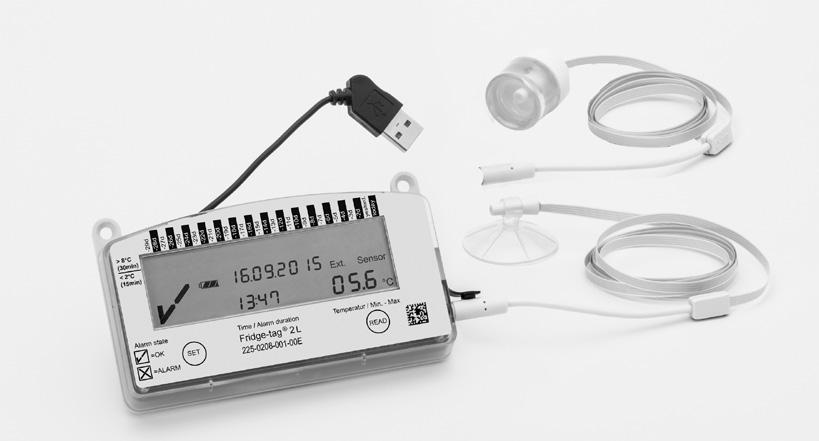


1 Fridge-tag 2 L with external sensor OPERATION MANUAL
2 Content ) Display explanations 3 2) State of delivery / Sleep Mode 4 3) Quality check prior to activation 4 4) Placing the sensor of the Fridge-tag 2 L 6 5) Activation process 7 5.) Overview sequences of activation 8 5.2) Activation 8 5.3) Setting the calendar format 8 5.4) Use of and 9 5.5) Setting the date 0 5.6) Setting the time 2 5.7) Setting the alarm limits (not standard) 4 5.8) Connection error 8 6) Read and change settings / How to correct setting mistakes 9 6.) Overview menu 9 6.2) Menu entry 20 7) Display indication during measurement 22 8) Warning symbol 23 9) Reading the History 23 9.) Option : Read out day-per-day (30 day history) ) Option 2: Read out alarms (Alarm-Super-Jump functio 26 Read out audio Alarm ) Option 3: Read out history via computer ) Temperature record duration 3 9.5) Veryfication process 32 0) Explanation of terms ) Expiry code explanation 2) Technical specifications 3) Important Information Page
3 ) Display explanations Ext. Int.Sensor 5! 8888 min max. F C English OK ( ) or ALARM (X) indicator Daily HIGH / LOW alarm indicator (showing history of the last 30 days) Power on indicator (double point is flashing) Battery power This icon indicates the remaining capacity of the battery Additional warning symbol Time, duration and text indicator Date and text indicator Indicator of measured minimum/maximum temperature Temperature display Indicator of the temperature measurement unit ( F / C) Indicator of activated sensor: Int. = internal sensor (inside the Fridge-tag 2 L) Ext. = external sensor (cable with temperature sensor) 3
4 2) State of delivery / Sleep Mode Fridge-tag 2 L ext. sensor is shipped in its so-called Sleep Mode. >8 C (30mi <2 C (5mi Alarm state Temperature (min/max) E The display (LCD) is blank. 3) Quality check prior to activation (in Sleep Mode) The following chart shows which information will be indicated on the LCD screen upon successive button pressing while in Sleep Mode. After approx. 60 seconds without any button pressing the Fridgetag 2 L ext. sensor goes back into Sleep Mode; the display is blank again. >8 C (30mi <2 C (5mi Alarm state Temperature (min/max) E Press continuously to readout information 4
5 Pressing the -button Displayed Information st press of : ! 8888 min nd press of : P4n SS 3rd press of : 4th press of : d u r 00 max. F C H Ext. Sensor 258 C Cd 5th press of *: 80 0 C 6th press of *: Ext. Int.Sensor d u r L th press of : C S 8th press of : PCb 9th press of : C 4n P th press of : Display test: all segments activated Indication of date and production test result: 6. September 205 / PASS Indication of the current temperature and which sensor is activated (--.- C if ext. sensor is not connected) Indication of configuration ID number (e.g. 234) Indication of upper alarm settings. Example shows duration and temperature limits: 0 hours, >+8 C, high Indication lower alarm settings: example shows duration and temperture limits: 60 min., <-0.5 C, low Serial number of the device PCb number (manufacturer information only) Battery power: 3 bar = full (>70%) 2 bar = half-full (30-70%) bar* = low (0-30%) *Device should be replaced. English The display is blank again. *(only indicated if factory preset, otherwise skipped) 5

6 4) Placing the sensor of the Fridge-tag 2 L Fridge-tag 2 L with an external sensor Two hours before activating the Fridge-tag 2 L the external sensor must be placed in its predetermined location. It is recommended and important to place the external sensor as close to the supervised goods as possible to ensure a perfect temperature observation. For the right positioning of the ext. sensor within the fridge, please follow the instructions of WHO, CDC or any other governmental requirements of your country (for more information visit 6
7 5) Activation process 5.) Overview sequences of activation English State of delivery 5.2) Activation 5.3) Setting the calendar format 5.5) Setting the date 5.6) Setting the time 5.7) Setting the alarm limits (only if factory preset otherwise skipped) 5.8) Connection error NOTE: If the activation process has not been completed - after approx. 60 seconds without any button operation - the device will go back into sleep mode. The activation starts from the beginning. If you want to read or change settings (e.g. change F to C) after the activation has been completed, proceed as described in chapter Read and Change settings / How to correct setting mistakes 7
8 5.2) Activation To activate the device press the and the button simultaneously for more than 3 seconds. m state Temperature (min/max) E Successful activation is visible when the following will appear on the screen: dd yyyy 5.3) Setting the calendar format Option : Setting the date format to: dd.mm.yyyy dd yyyy m state Temperature (min/max) E 05 Press to save the calendar format 8
9 Option 2: Setting the date format to: mm.dd.yyyy C mi C mi arm state 2 ddyyyy Then press to save the calendar format Temperature (min/max) Press to change the calendar format After setting the caldendar format, the first digit of the date will start flashing. 5.4) Instruction for the use of the and the button The button is used to adjust the number. Each time you press the button, the number in the flashing digit will increase by. If you press more than necessary continue pressing the button until you obtain the desired number. M E Temperature (min/ma Press to adjust the number English The button is used to save the number. After pressing the button the next digit will start flashing. Temperature (min/ma M E Press to confirm Note: If is pressed mistakenly, continue with the set up. Instructions for changing the mistake are described in chapter Read and change settings / How to correct setting mistakes 9
10 5.5) Setting the date The following example shows how to set the date to: 6th Sep. 205 ( ) in Europe format ) ) 0205 The first digit is flashing: m state 2 Temperature (min/max) E 05 Press to save Press until appears as the first digit C i i The second digit is flashing: m state 2 Temperature (min/max) E 05 Press to save Press until 6 appears as the second digit 0
11 C The third digit is flashing: English m state 2 Temperature (min/max) E 05 Press to save Press until 0 appears as the third digit The fourth digit is flashing: m state C i i 2 Temperature (min/max) E 05 Press to save Note: The fifth and sixth digit is set automatically Press until. 9 appears as the fourth digit The seventh digit is flashing: rm state 2 Temperature (min/max) E 05 Press to save Press until appears as the seventh digit
12 i The eighth digit is flashing: i m state Temperature (min/max) E 05 2 Press to save Press until 2 appears as the eighth digit The date is now set to: After setting the date, the first digit of the time will start flashing. 5.6) Setting the time This example shows how to set the time to: 3:47 Note: The clock function operates as a 24 hour clock (e.g. :47 pm = 3:47) The first digit is flashing: m state Temperature (min/max) E 2 Press to save Press until appears as the first digit 2
13 m state Press to save Temperature (min/max) The second digit is flashing: Press until 3 appears as the second digit English m state Press to save Temperature (min/max) The third digit is flashing: Press until 4 appears as the third digit m state Press to save Temperature (min/max) The fourth digit is flashing: Press until 7 appears as the fourth digit The time is now set to: 3:47 If you want to read or change settings (e.g. change F to C) after the activation has been completed, proceed as described in chapter Read and Change settings / How to correct setting mistakes 3
14 If the device is configured with self-programmable alarm limits proceed with the following chapter. If not, the activation is now completed. Connect the device with the external sensor and continue with chapter 5.8 Connection error. Note: During max. minute after the connection no temperature is displayed on the screen. 5.7) Setting the alarm limits (Not standard, only by special order) This adjustment is done in 4 steps: ) Setting the duration of the upper alarm limit 2) Setting the temperature of the upper alarm limit 3) Setting the duration to the lower alarm limit 4) Setting the temperature of the lower alarm limit ) and 3) Setting the HI & LO alarm duration, they are completed in the same manner te ARM 2 d u r 000 Fridge-tag 2 L E H Temperature (min/ma Press to confirm the number The first digit is flashing: Press to adjust the number. d u r 0200 H The second digit is flashing: te ARM E Temperature (min/ma 2 Press to confirm the number Press to adjust the number. 4
15 te ARM d u r E H Temperature (min/ma 2 Press to confirm the number The third digit is flashing: Press to adjust the number. English d u r 0200 H The fourth digit is flashing: te ARM E Temperature (min/max Press to confirm the number Press to adjust the number. The duration of the alarm limit is now set. 2) and 4) Setting the HI & LO alarm duration, they are completed in the same manner Note: Alarm temperature limits must be no lower than -35 C (-3 F) and no higher than +55 C (+3 F). First you have to choose the range of the desired temperature limit. You have the choice between negative and positive temperatures. In case of a positive limit in Fahrenheit scale you may further choose if the limit shall be equal or above +00 F. This choice is done by repetitively pressing until the desired range is indicated. Note: The temperature measurement unit ( C / F) can only be changed after the device is activated in the menu. Go to chapter Read and change settings / How to correct setting mistakes. 5
16 Instruction for setting a positive temperature limit between 0 C / 0 F and +55 C / +3 F C mi C mi arm state H 80 C Temperature (min/max) Press until the display shows no flashing sign: 2 Press to adjust the limit between 0 C / 0 F and +55 C / +3 F The next digit can now be set. Press until you reach the desired number. Then press to confirm it. Then the next digit will start flashing. Continue until all digits of the alarm temperature are set. Instruction for setting a positive Fahrenheit temperature limit equal or above +00 F (Important: the maximum Celsius temperature is +55 C. This Option is only for temperatures in Fahrenheit) C mi C mi arm state 2 H 080 Temperature (min/max) Press to adjust the limit equal or above +00 F Press until a flashing leading is indicated on the display: The next digit of the temperature starts flashing. Set the number and continue until all digits of the alarm temperature are set. F 6
17 Setting a negative temperature limit below 0 C / 0 F English m state 2 H - 80 C Temperature (min/max) E 05 Press to set the limit below 0 C / 0 F Press until the flashing - sign is indicated on the screen: The next digit can now be set. Press until you reach the desired number. Then press to confirm it. Then the next digit will start flashing. Continue until all digits of the alarm temperature are set. As soon as the parameters of the upper alarm limit are set, the first digit of the duration of the lower alarm limit will start flashing. Proceed the same way as you did with the upper alarm limit. As soon as the last digit of the lower alarm limit is confirmed, the activation is completed. Connect the device with the external sensor. NOTE: In case the desired temperature limit cannot be confirmed, check if the temperature is set within the allowed operating temperature range. 7
18 5.8) Connection error After 0 minutes without a connection between the device and the sensor, the following alarm will be shown on the display. >+8 C 0hrs) -0.5C 0mi! Please check the following two points:. If the sensor of the Fridge-tag 2 L is properly connected with the device. Be sure to firmly press and twist the connector until you hear it click into place. 2. If the sensor cable of the Fridge-tag 2 L has any defects. As soon as one of the above mentioned errors have been fixed, the display shows current temperature again, the measuring will now continue Ext. Sensor C Alarm state Fridge-tag 2 L Temperatur / Min. - Max Ext. Sensor C Temperature (min/max) Note: During max. minute after the connection no temperature is displayed on the screen. 8
19 6) Read and change settings / How to correct setting mistakes 6.) Overview menu English Device activated 6.2) Menu entry 6.2.) Menu: DATE (Change date and / or time) 6.2.2) Menu: CONF (Read alarm configurations) 6.2.3) Menu: CELS FAHR (change alarm configurations) 6.2.4) Menu: CONF (only if factory preset otherwise skipped) NOTE: If you scroll through the menu and you reach the display of the measuring mode again you need to restart from the begining by accessing the menu. In order to adjust more than one setting (e.g. time & Celsius to Fahrenheit) you must complete each change and return to menu mode for the 2nd change. 9
20 6.2) Menu entry to read and change settings To change the date format, the date, the time, the temperature measurement unit or the alarm settings or to read the pre-set alarm limits please proceed as follows: e RM E Press and continue to 2...then press hold... shortly 3...then release both buttons simultaneously OUT SIDE is now displayed on the screen. You have now entered change mode and you may choose which item you want to change You can access the following 4 menus: OUT SIDE - first screen, shows the temperature measured with the int. sensor of the Fridge-tag 2 L (normal ambient temperature) ) DATE - change date and / or time settings 2) CONF - read the alarm settings 3) CELS FAHR - change to Celsius or Fahrenheit 4) CONF - change the alarm settings (only if factory pre-set) Use the button to scroll through the menu. Use the button to access the corresponding menu. 6.2.) Access the menu DATE The display shows the menu OUT SIDE. Press until the display shows DATE. Now you can adjust the date format, date or time settings. Then follow the steps as described in chapter Setting the date and time. Information: Time and date adjustments have no effect on the alarm records. Once the device is activated, it cannot be stopped anymore. 20
21 The number of time adjustments during the same day is unlimited. Note: After the adjustment has been done, the Fridgetag 2 L ext. sensor will be locked for 24 hours after the clock passes midnight and through the entire next day. (e.g. changes on the 5th Sep., device locked from 00:0 am on the 6th until 00.0 am on the 7th). This is for security reasons. English NOTE: If you experience this problem please wait for the time on the device to cross over midnight and try again ) Access the menu CONF The display shows the menu OUT SIDE. Press until the display shows CONF. Then Press to access the menu to read the current alarm configurations. First the display check appears. Then continuously press to scroll through the pre-set alarm parameters ) Access the menu CELS FAHR The display shows the menu OUT SIDE. Press until the display shows CELS FAHR. Then Press to access the menu to change the temperature measurement unit. To change the measurement unit (Celsius / Fahrenheit) press until the display shows the desired sign ( C/ F). Press to confirm the mesurement unit )* Access the menu CONF The display shows the menu OUT SIDE. Press until the display shows CONF. Press to access the menu to change the alarm configurations. To change the alarm limits (duration or temperature) please proceed as described in chapter Setting the alarm limits. *Changes of the alarm limits are only possible for devices which are programmed with this feature. 2
22 7) Display indication during measurement mode For max. minute after completing the settings or after connecting the device with the sensor, the following display will appear. >8 C (30mi <2 C (5mi Alarm state d u r max E Ext. Sensor --- C Temperature (min/max) For a maximum of minute no current temperature is displayed on the screen, indicated by (--.-). Example of OK Display - during measurement i i rm state Ext. Sensor 3 C 056 Temperature (min/max) Once the device is fully activated the ( ) OK symbol, the current temperature reading, the time and the date will be displayed on the screen. The Fridge-tag 2 L will also indicate that the measuring is made with an external sensor. A ( ) (OK symbol) is indicated during normal operation as long as no alarms have been recorded. The temperature and time conditions were within the preset alarm parameters. 22
23 Example of ALARM Display - during measurement i English i rm state! Sensor C Temperature (min/max) If the temperature and time conditions are outside the preset alarm parameters the following will be displayed on the screen: The ( ) OK symbol will be replaced by (X) ALARM symbol An additional arrow will be indicated in the upper display area to show which ALARM limit has been violated and on which day. In addition to the (X) ALARM symbol the warning symbol (!) will appear beside the (X).! 8) Warning symbol! Option : The warning symbol will remain visible until the user reads the details of the triggered alarm/s from the display. After that it will disappear. ALARM indications cannot be cancelled nor reset. Option 2: The warning and ALARM symbol (X) will remain visible until the user reads the details of the triggered alarm/s from the display. After that both symbols will disappear and the display will go back to the OK Symbol ( ). Note: How the ALARM symbol (X) and the warning symbol react is specified in the configuration of the device. 9) Reading the History The information of the temperature excursions can either be viewed directly on the device for the past 30 days or on the generated files (PDF/ASCII) for 28, 56, 84 or 2 days, depending upon how the device is configured. Ext. 23
24 Note: The external sensor of the Fridge-tag 2 L can remain at it s location for the read out process. Please consider, that a connection error will occur if the sensor is disconnected from the Fridge-tag 2 L for more than 0 minutes. This alarm can be cleared - see how in chapter ) Option : Read out day-per-day directly on the device (30 day history) Example of an OK display - during read out of the history state OK ALARM d u r 0032 max E The following information is indicated on the screen: Ext. Sensor 05 C Temperature (min/max) Press once The OK symbol The corresponding arrow (example: high arrow of ) Highest recorded temperature (example: +0.5 C) The time duration out of the preset temperature high limit (example 00:32; hrs: mi. m state d u r 0 00 Ext. Sensor 0 min. 029 C Temperature (min/max) E The following information is indicated on the screen: Press a second time 24
25 The OK symbol The corresponding arrow (example: low arrow of ) Lowest recorded temperature (example: +2.9 C) The time duration out of the preset temperature low limit (example 00:00; hrs: mi. Note: Continue repetitively pressing the button to read out day per day the details of the past 30 days. Information: When you reach an ALARM event, the indication on the screen of the Fridge-tag 2 L ext. sensor will be different to the indication of an OK display. English Example of an ALARM display - during reading out of the history st displayed screen of a lower ALARM event! m state Temperature (min/max) Press The following information is indicated on the screen: The ALARM symbol The corresponding arrow: Lower ALARM limit Day of Alarm: 3 days ago () The date of excursion: The time of excursion: 8:2 25
26 2nd displayed screen of a lower ALARM event : ) ) m state d u r! - Ext. Sensor 035 min. 0 Temperature (min/max) E 05 Press a second time The following additional information is indicated on the screen: Lowest recorded temperature: -. C The time duration out of the preset temperature low limit: 0:35; hrs:min Temperature recording with: external sensor 9.2) Option 2: Read out only alarms on the screen (Alarm-Super-Jump function, 30 day history) If you like to read out only the ALARMS directly on the device, press and hold the button for at least 3 seconds. These steps will also stop the device from beeping, except the temperature is still out of the allowed temperature range. st displayed screen of the latest ALARM event:! m state Temperature (min/max) E 05 Press for 3 seconds 26
27 The following information is indicated on the screen: The ALARM symbol The corresponding arrow: Upper ALARM limit Day of Alarm: 3 days ago () The date of excursion: The time of excursion: 20:30 English 2nd displayed screen of the latest ALARM event m state d u r 24 Ext. Sensor max.! 05 Temperature (min/max) E 05 Then press again The following additional information is indicated on the screen: Highest recorded temperature (example: +0.5 C) The time duration out of the preset temperature high limit (example :24; hrs:mi. Temperature recording with: external sensor Information: Press and hold the button again for at least 3 seconds and the next Alarm event will appear on the screen. 27
")
28 Read out Audio ALARM (optional factory setting) In case of an upper or lower temperature overrun, 3 audible ALARM signals will be triggered immediately. (500ms ON / 500ms OFF). Thereafter: During 0 minutes Every minute ALARM -signal During 50 minutes Every 0 minutes ALARM -signal During hours Every hour ALARM -signal Acknowledge audible ALARM: Press the button (repeatedly) 9.3) Option 3: Read out data from the files generated by the Fridge-tag 2 L with ext. sensor by connecting it with a computer Plug the Fridge-tag 2 L into any computer via USB Interface. Make sure the device is plugged in properly. Wait sufficient time for the device to generate the ASCII and PDF files (depending on the programming, this process may take a couple of minutes). You can see that the device is working from the continuously appearing arrows in the upper display area. 28


29 When the report creation is complete, one of the following windows will appear: Open the appropriate file generated by the Fridge-tag 2 L. English Information: For this process no additional software is necessary. Note: For a proper USB-port disconnection of the device, please always use the safely remove hardware function on your PC/Mac. Right mouse click on the icon. Eject (choose the right device to remove). Do not disconnect the device before you receive the following message, otherwise this could damage the device! 29


30 Sample of a PDF-file Page /2 If you need to use the individual temperature readings please open the ASCII file. Scroll down in order to find the recordings of temperatures stamped with the date and time based on the logging interval. Page 2/2.txt file 30
31 9.4) Temperature record duration (optional factory setting) Selectable record duration: 28, 56, 84, 2 days. Information: File names on the Fridge-tag 2 L ext. sensor are write protected. The names may only be changed after downloading onto a computer. Changing is either possible directly on unopened files or via open and save commands with the Adobe Reader. Using other programs may cause loss of the digital signature. Explanation of PDF report: Date Event: t Event: a Average temp. Status: in progress Status: OK Status: ALARM! Status: ALARM Min. temp. Cum. duration out of range Alarm trigger time Max. temp. Duration * For more information go to chapter 8 Warning symbol Date of measurement Time / date changed Alarm configuration changed Average temperature The data collection of Today is not yet complete No alarm has been triggered the past 30 days (No alarm has yet been triggered since the last data read out on the device.*) Alarm/s have been triggered (With! means that the details of the corresponding alarm have not been read out yet*) Alarm/s have been triggered (Without! means that the details of the corresponding alarm have already been read out on the device*) Lowest recorded temperature Cumulative daily time outside of the alarm limits Time at which the alarm was triggered Highest recorded temperature Duration of an external sensor connection error English 3
. st step: Download the software Verifier from our website: www.berlinger.")
32 9.5) Veryfication process This process is to verify if the files (PDF and ASCII-file) created by the Fridge-tag 2 L ext. sensor are authentic and have not been manipulated or accidentally changed (meets the strict FDA CFR 2 Part requirements). st step: Download the software Verifier from our website: 2nd step: Open the software. The following window will appear: 3rd step: Click on Open file 4th step: Select the file you would like to verify. Option : Select the files directly from the Fridge-tag 2 L ext. sensor which is connected to your computer. Option 2: Select the files from the place where you saved them on your computer. When the file is correct and in its original condition, the following window will appear: In case the file has been changed, an error message will appear. Proceed the same way with the PDF or the.txt -file. The same OK or ERROR messages will appear. 32
33 0) Explanations of terms Read out mode In order to avoid incorrect data, the Fridge-tag 2 L ext. sensor does not collect any readings while in the Adjustment or Read-out mode (e.g. changing time, date and during reading of history). The Fridge-tag 2 L ext. sensor will fall back into normal operation after approx. 60 seconds without pressing any buttons. After 0 minutes without a connection between the sensor and the device, an alarm will be shown on the display. HI or LO indicator (with an external sensor) If the Fridge-tag 2 L ext. sensor measures temperatures above +55 C or below -40 C, it shows HI and LO on the screen and also in its extreme temperature memory. The regular measurements and monitoring of alarm limits will continue as usual. As soon as the temperature is between +55 ºC and -40 ºC numbers will be displayed again. ) Expire code explanation Sample: exp The sample shows the expiry date of the Fridge-tag 2 L ext. sensor as July 206 (206-07). More information about the Fridge-tag 2 L ext. sensor can be found in the sales brochure and on the website: 2) Technical specifications Storage condition (inactive) 0 C to +30 C Operating temperature (ext. sensor) -40 C to +60 C Accuracy of temperature +/- 0.8 C (-40 C to -30 C) measurement (ext. sensor) +/- 0.5 C (-30 C to +40 C) +/- 0.8 C (+40 C to +60 C) Accuracy of time measurement +/- 30 minutes/year Temperature measurement interval every minute Operating lifetime up to 3 years (check battery indicator) Protection class IP64 English 33
34 3) Important Information Liability The manufacturer shall not be held liable: if the device was used beyond the manufacturer s given limitations. for any claims due to the improper storage and use of the device. for any problems with the temperature controlling and / or cooling unit. for the bad quality of any monitored goods. for incorrect readings if the device was used beyond its expiry date. Warranty: 2 years from date of delivery. Battery The Fridge-tag 2 L ext. sensor contains a CR Lithium battery. Please pay strict attention to the following points: The housing of the Fridge-tag 2 L ext. sensor must never be opened nor destroyed. Never expose the Fridge-tag 2 L ext. sensor to temperatures above the allowed range (fire, oven, micro waves, etc.).it may cause injuries. Always keep the Fridge-tag 2 L ext. sensor out of the reach of Children. The battery complies with IATA DGR Packaging Instruction 970 Section 2 and is therefore not considered as dangerous good. Dispose or recycle the Fridge-tag 2 L in accordance with the WEEE 202/9/EU guidlines or your local regulations. The device may also be returned to the manufacturer for proper recycling. Useful life The devices can be used up to 3 /2 years after production date (/2 year storage / 3 years useful life) on the condition that: the buttons are not pressed for very long time, e.g. if jammed between the goods in a shipment. storage and operation of the device should remain inside the recommendations of the manufacturer, especially temperatures below 0 C or +32 F could have a negative influence for the operating lifetime of the battery. The end of the useful life is indicated by the low battery indicator on the display (go to page 5 display explanation ). Attention The Fridge-tag 2 L ext. sensor monitors temperature exposure and not the product quality. Its purpose is to signal if product quality evaluation or testing is required. 34

35 English Manufacturer: Q-tag AG Mitteldorfstrasse Ganterschwil Switzerland Sales: Berlinger & Co. AG Mitteldorfstrasse Ganterschwil Switzerland Tel.: Fax: info@berlinger.com Web: Berlinger USA, LLC 222 Turnpike Road Suite 3 Westborough, MA 058 Tel.: Fax: info.us@berlinger.com Web: _Release_.2 Subjet to change. Please note that all information in this document is correct at the time of publication. Due to our policy of continuous product development, we reserve the right to change this information without prior notice. 35
Fridge-tag 2 L OPERATION MANUAL ENGLISH PAGE 1-34 GEBRAUCHSANWEISUNG DEUTSCH SEITE with internal sensor
 Fridge-tag 2 L with internal sensor OPERATION MANUAL ENGLISH PAGE -34 GEBRAUCHSANWEISUNG DEUTSCH SEITE 35-68 Content ) Display explanations 3 2) State of delivery / Sleep Mode 4 3) Quality check prior
Fridge-tag 2 OPERATION MANUAL ENGLISH PAGE 1-35 GEBRAUCHSANWEISUNG DEUTSCH SEITE with external sensor
 with external sensor OPERATION MANUAL ENGLISH PAGE -35 GEBRAUHSANWEISUNG DEUTSH SEITE 36-70 ontent Page ) Display explanations 3 2) State of delivery / Sleep Mode 4 3) Gathering information prior to device
Fridge-tag 2 E OPERATION MANUAL ENGLISH PAGE 1-36 MODE D EMPLOI FRANCAIS PAGE with internal sensor
 with internal sensor OPERATION MANUAL ENGLISH PAGE -36 MODE D EMPLOI FRANAIS PAGE 37-7 ontent Page ) Display explanations 3 2) State of delivery / Sleep Mode 4 3) Gathering information prior to device
Fridge-tag 2 OPERATION MANUAL ENGLISH PAGE 1-36 GEBRAUCHSANWEISUNG DEUTSCH SEITE with internal sensor
 with internal sensor OPERATION MANUAL ENGLISH PAGE -36 GEBRAUHSANWEISUNG DEUTSH SEITE 37-7 ontent Page ) Display explanations 3 2) State of delivery / Sleep Mode 4 3) Gathering information prior to device
Fridge-tag 2 OPERATION MANUAL ENGLISH PAGE 1-34 GEBRAUCHSANWEISUNG DEUTSCH SEITE with internal sensor
 with internal sensor OPERATION MANUAL ENGLISH PAGE -34 GEBRAUHSANWEISUNG DEUTSH SEITE 35-68 ontent ) Display explanations ) State of delivery / Sleep Mode 3) Gathering information prior to device activation
Q-tag CLm doc family Type: doc / doc L / doc LR / doc D
 Q-tag CLm doc family Type: doc / doc L / doc LR / doc D Q-tag CLm doc The clever one Q-tag CLm doc LR The profitable one Q-tag CLm doc L The durable one Q-tag CLm doc D The cool one To monitor your transport
WHO PQS-Code E006/020. Fridge-tag 2 Storage temperature monitor with USB port
 WHO PQS-Code E006/020 Fridge-tag 2 Storage temperature monitor with USB port Precision monitoring in fridges, cold rooms and displays: in hospitals and clinics in pharmacies and chemists in health centers
NYS Vaccines for Children (VFC) Program Fridge-Tag 2L Data Logger: Implementation and User Guide
 Program Fridge-Tag 2L Data Logger: Implementation and User Guide") NYS Vaccines for Children (VFC) Program Fridge-Tag 2L Data Logger: Implementation and User Guide Contents Purpose... 2 Equipment Checklist... 2 Calibration Certificates... 3 Setup... 4 Fridge-Tag 2L Glycol/Probe
NYS Vaccines for Children (VFC) Program Fridge-Tag 2L Data Logger: Implementation and User Guide Contents Purpose... 2 Equipment Checklist... 2 Calibration Certificates... 3 Setup... 4 Fridge-Tag 2L Glycol/Probe
WHO PQS-Code E006/016. Q-tag CLm doc USB Multi- Limit Temperature Indicator
 WHO PQS-Code E006/016 Q-tag CLm doc USB Multi- Limit Temperature Indicator Q-tag CLm doc management by excursion via USB Start it. Dock it. Pack it. Send it. File it. ERP-System E-Mail Excel Data Management
USER MANUAL. ITAG 4 / ITAG 4 Bio/ ITAG 4 TH DATA LOGGER. UM-ITAG REV.B 03/02/2016
 USER MANUAL EN ITAG 4 / ITAG 4 Bio/ ITAG 4 TH DATA LOGGER Updated@ 03/02/2016 CONTENTS Product Overview... 3 Logger... 3 LCD... 4 Technical Specifications... 5 TEMPCENTRE SOFTWARE... 6 How to download
Are you still stuck with the current status of manual thermometer recording? X Labor Intensive X No History X Inaccurate
 Fridge-tag 2 Current Status Are you still stuck with the current status of manual thermometer recording? X Labor Intensive X No History X Inaccurate Future State with The Fridge-tag 2 The future is here
LogTag Recorders TRED30-16R. Temperature Recorder with Display and 30 Day Statistics Memory. Product User Guide
 LogTag Recorders TRED30-16R Temperature Recorder with Display and 30 Day Statistics Memory Product User Guide Document Release Version: 1.4 Published 1. March 2017 Copyright LogTag Recorders, 2004-2017
i.c³ User Guide For Helmer i.series Ultra-Low Freezers A/A
 i.c³ User Guide For Helmer i.series Ultra-Low Freezers 360175-A/A Document History Revision Date CO Supersession Revision Description A 18 APR 2014* 9275 n/a Initial release. * Date submitted or change
Step-by-step interpretation of 10-day electronic temperature monitoring devices for international vaccine shipments
 Step-by-step interpretation of 10-day electronic temperature monitoring devices for international vaccine shipments What information old guidelines provide? 2000 guidelines Inclusion of 1 CCM and 1 freeze
User Manual. Dryer Controller M720
 User Manual Dryer Controller M720 Hardware version 1.00 Software version 1.00 Preliminary version Manual M720 Dryer controller Page 1 of 42 Document history Preliminary version: - Created in April, 2009
UTRED day Logger with display
 UTRED30-16 30 day Logger with display Technical User Manual Published September 2018 Copyright LogTag Recorders, 2018 Contents Safety Information... 3 Liability... 3 Battery Life... 3 Disclaimer... 3 Typographical
LogTag Recorders Ltd TRED30-16R. Temperature Recorder with Display and 30 Day Statistics Memory. Product User Guide
 LogTag Recorders Ltd TRED30-16R Temperature Recorder with Display and 30 Day Statistics Memory Product User Guide Document Release Version: 1.3 Published 1 September 2016 Copyright LogTag Recorders, 2004-2016
Follett Performance Plus
 Follett Performance Plus touchscreen user guide The next level of control in undercounter refrigeration Controller Operation - Performance Plus touchscreen Use and care of the LCD Performance Plus touchscreen
PRODUCT SPECIFICATION
 LogTag TEMPERATURE RECORDER Temperature Recorder / Data logger with 30 Day summary display LOGDISP PRODUCT SPECIFICATION Doc Ver 1.1 Released : 4 th May 2010 Copyright 2010, LogTag Recorders Limited LOGDISP
iminiplus PDF User Guide Version 2.0
 iminiplus PDF User Guide Version 2.0 Table of contents 1 Scope of this document... 3 2 Why PDF?... 3 3 Logger profile... 3 4 What you need to get started... 4 5 FDA 21 CFR Part 11 compliance... 5 6 How
UTRED30-WiFi. 30 day WiFi Logger with display
 UTRED30-WiFi 30 day WiFi Logger with display Technical User Manual Published September 2018 Copyright LogTag Recorders, 2018 Contents Safety Information... 3 Liability... 3 Battery Life... 3 Disclaimer...
Specifications Minimum Typical Maximum Unit
 Temperature Probe Data Logger with LCD and USB Interface ORDERING INFORMATION Standard Data Logger (Data Logger, 1m Thermistor Probe, Software on CD and Battery) Replacement Battery LASREC028 LASACC001
EL-USB-1-LCD Temperature Data Logger with LCD
 99 Washington Street Melrose, MA 02176 Phone 781-665-1400 Toll Free 1-800-517-8431 EL-USB-1-LCD Temperature Data Logger with LCD Visit us at www.testequipmentdepot.com ORDERING INFORMATION Standard Data
Instruction Sheet THERMOCOUPLE DATA LOGGER WITH LCD DISPLAY AND USB INTERFACE
 Instruction Sheet OM-EL-USB-TC-LCD THERMOCOUPLE DATA LOGGER WITH LCD DISPLAY AND USB INTERFACE Thermocouple Data Logger with LCD ORDERING INFORMATION Standard Data Logger OM-EL-USB-TC-LCD (Data Logger,
LineGuard 2300 Program User Manual (FloBoss 107)
") Form A6251 Part Number D301346X012 November 2012 LineGuard 2300 Program User Manual (FloBoss 107) Remote Automation Solutions Revision Tracking Sheet November 2012 This manual may be revised periodically
Form A6251 Part Number D301346X012 November 2012 LineGuard 2300 Program User Manual (FloBoss 107) Remote Automation Solutions Revision Tracking Sheet November 2012 This manual may be revised periodically
2014, TempSen Electronics Company
 USER MANUAL EN TempSen Alpha T30 / TH30 / T50X / TD80 / TD80S / TUX Updated@ 07/06/2015 www.alphalogger.com www.tempsen.com/alpha 2014, TempSen Electronics Company www.tempsen.com Contents Products Overview...
User Manual. Humidity-Temperature Chart Recorder. Model RH520
 User Manual Humidity-Temperature Chart Recorder Model RH520 Introduction Congratulations on your purchase of the Extech RH520 Temperature + Humidity Chart Recorder. The RH520 measures and displays Temperature,
HOBO U14 Data Logger User Manual
 HOBO U14 Data Logger User Manual The U family of data loggers offers reliability and convenient monitoring for applications that require higher accuracy, better resolution, more memory, or USB connectivity
DYGIZONE GJD910 Lighting Controller & Enunciator
 DYGIZONE GJD910 Lighting Controller & Enunciator MASTER WIRING IDENTIFICATION Power up to the DygiZone and you will see: All the LED s (red,yellow,green and blue buttons) will flash All the LCD icons will
LogTag TICT - is0 Tag
 TICT - is0 Tag Freeze Indicator with display DOCUMENT REVISION 1.0, 4 March 2014 Copyright 2014, LogTag Recorders Limited Contents Contents... 2 Document revision history... 2 Description... 3 Alerts...
EL-USB-2-LCD+ High Accuracy Humidity, Temperature and Dew Point Data Logger with LCD
 High Accuracy Humidity, Temperature and Dew Point Data Logger with LCD ORDERING INFORMATION Standard Data Logger (Data Logger, Software on CD, Battery) Replacement Battery 99 Washington Street Melrose,
TS400. Operating Manual. Test Station for Microtector II Series (G450/G460)
") Operating Manual TS400 Test Station for Microtector II Series (G450/G460) GfG GESELLSCHAFT FÜR GERÄTEBAU MBH KLÖNNESTRASSE 99 44143 DORTMUND, Germany TEL. +49 / (0)2 31 / 5 64 00 0 FAX +49 / (0)2 31 /
Operating Manual TS400 Test Station for Microtector II Series (G450/G460) GfG GESELLSCHAFT FÜR GERÄTEBAU MBH KLÖNNESTRASSE 99 44143 DORTMUND, Germany TEL. +49 / (0)2 31 / 5 64 00 0 FAX +49 / (0)2 31 /
Dryer Controller M720
 User Manual Dryer Controller M720 Hardware version 2.00 Software version 2.00 Manual M720 Dryer controller Page 1 of 60 Document history Preliminary version: - Created in April, 2009 Hardware Version 2.00,
Ambient Temperature/ Relative Humidity & Dew Point Temperature Sensors to USB Output. Model LFS108B
 Ambient Temperature/ Relative Humidity & Dew Point Temperature Sensors to USB Output Model LFS108B Copyright 2018 - LLC. All rights reserved. Table of Contents Quick Start... 3 1- Introduction... 4 2-
Dashboard for Windows V1.1.0
 User manual Dashboard for Windows V1.1.0 TBS Electronics BV De Factorij 46 1689 AL Zwaag The Netherlands www.tbs-electronics.com COPYRIGHT 2009 (rev1e) - 1 - TABLE OF CONTENTS 1. INTRODUCTION......................
Spa Touch Control Panel with BP2100, BP6013 spa controllers. (Spa Owner s Manual insert)
") Spa Touch Control Panel with BP2100, BP6013 spa controllers. (Spa Owner s Manual insert) P.N. 7876C (export) February 12, 2015 For Spas equipped with BP2100, BP6013 controllers and Spa Touch panel. Spa
Spa Touch Control Panel with BP2100, BP6013 spa controllers. (Spa Owner s Manual insert) P.N. 7876C (export) February 12, 2015 For Spas equipped with BP2100, BP6013 controllers and Spa Touch panel. Spa
EasyTronic III MANUAL SERVICE
 rev.6 EasyTronic III MANUAL SERVICE General characteristics: Power supply 24 Vac ±15% Max consumption at 24Vac 300mA Relay outputs 6 Maximum relay current 8 A res. Serial standard RS232 2 Serial standard
Operations Manual TS400. Test Station for G450/G460 Gas Detector
 TS400 Test Station for G450/G460 Gas Detector Operations Manual 1194 Oak Valley Dr, Ste 20, Ann Arbor MI 48108 USA (800) 959-0329 (734) 769-0573 www.goodforgas.com GfG Products for Increased Safety Congratulations
Spa Touch Control Panel with 2000, 2100 controllers. (Spa Owner s Manual insert)
") Spa Touch Control Panel with 2000, 2100 controllers (Spa Owner s Manual insert) P.N. 7876B February 11, 2015 For Spas equipped with BP2000, BP2100 controllers and Spa Touch panel. Spa Touch Control Panel
Spa Touch Control Panel with 2000, 2100 controllers (Spa Owner s Manual insert) P.N. 7876B February 11, 2015 For Spas equipped with BP2000, BP2100 controllers and Spa Touch panel. Spa Touch Control Panel
EL-USB-1-LCD Temperature Data Logger with LCD
 Temperature Data Logger with LCD ORDERING INFORMATION Standard Data Logger (Data Logger, Software on CD, Battery) Replacement Battery EL-USB-1-LCD BAT 3V6 1/2AA FEATURES measurement range USB interface
Operations Manual TS400. Test Station for G450/G460 Gas Detector
 TS400 Test Station for G450/G460 Gas Detector Operations Manual 1194 Oak Valley Dr, Ste 20, Ann Arbor MI 48108 USA (800) 959-0329 (734) 769-0573 www.gfg-inc.com GfG Products for Increased Safety Congratulations
USER MANUAL Mobeye ThermoGuard CM2200
 USER MANUAL Mobeye ThermoGuard CM2200 SW version 1.n Attention! Very important This user manual contains important guidelines for the installation and usage of the Mobeye device as described in this manual.
On initial power up the thermostat will guide you through set up procedure for the following:
 Operating Guide: for the Warmup 3iE Programmable Thermostat INTRODUCTION Your thermostat s default screen is the Home Screen. This screen displays important information such as the time, current floor
GMH 285 / GMH 285-BNC
 GMH 285 GMH 285-BNC H69.0.01.6C-02 Operating Manual Pt1000 Precision Thermometer For exchangeable probes, with alarm as of version V1.0 GMH 285 / GMH 285-BNC GMH-GREISINGER GMH-GREISINGER WEEE-Reg.-Nr.
THERMO BUTTON HYGRO BUTTON The smallest temperature and humidity loggers in the world!
 THERMO BUTTON HYGRO BUTTON The smallest temperature and humidity loggers in the world! FOR ALL YOUR TEMPERATURE AND HUMIDITY CONTROLS, PRODUCT TRACKING, TRANSPORT, STORAGE CONTROLS, HACCP! Small, rugged,
USB Multi Function Dataloggers. RHT30 Humidity/Temperature Datalogger. TH30 Dual Temperature Datalogger
 USER MANUAL USB Multi Function Dataloggers RHT30 Humidity/Temperature Datalogger TH30 Dual Temperature Datalogger Additional User Manual Translations available at www.extech.com Introduction Thank you
User Manual. Digi-Sense TC9500 Advanced Multiparameter Temperature Controller with Thermocouple, Thermistor, and RTD Inputs
 User Manual Digi-Sense TC9500 Advanced Multiparameter Temperature Controller with Thermocouple, Thermistor, and RTD Inputs Models 89800-03 and 89800-04 THE STANDARD IN PRECISION MEASUREMENT Table of Contents
CONTENTS. Backup Batteries
 WW85760 FAQS The links below will work in most PDF viewers and link to the topic area by clicking the link. We recommend Adobe Reader version 10 or greater available at: http://get.adobe.com/reader CONTENTS
Programmable Interactive User Manual
 67504B 02/16 (ALA) DH E RT 102/BW Programmable Interactive User Manual www.schluter.com 1. Contents 2. Menu Overview..............3 3. Introduction................ 4 4. General Operation............5 4.1.Navigation
C F AQ S C85183 FAQS AC Power Batteries Atomic Alarm Clock Factory Restart Atomic Alarm Clock AC Power Batteries Explanation:
 C85183 FAQS The links below will work in most PDF viewers and link to the topic area by clicking the link. We recommend Adobe Reader version 10 or greater available at: http://get.adobe.com/reader CONTENTS
Bacharach Bodyguard 4 User's Guide
 Bacharach Bodyguard 4 User's Guide This manual and the software described in it are copyrighted, with all rights reserved. Under the copyright laws, this manual or the software may not be copied, in whole
IDEAL E-NERGY Thermostat Touch type User Manual
 67800 03/18 (JRK) IDEAL E-NERGY Thermostat Touch type 203250 User Manual WWW.MFH-SYSTEMS.COM Contents Menu Overview............... 3 Introduction................. 4 Startup Wizard 1/2.............. 5 Startup
QD-ENG-68 Controller for Thermoelectric Thermal Management
 INSTALLING THE CONTROLLER QD-ENG-68 Controller for Thermoelectric Thermal Management The Ice Qube TMS controller is shipped complete with mounting hardware and electrical cables for easy installation.
MCD User Manual
 6759 08/5 ALA MCD5-999 User WWW.COMFORTHEAT.COM.AU < Contents > Contents Menu Overview................ 3 Introduction.................. Startup Wizard /2.............. 5 Startup Wizard 2/2..............
Test Equipment Depot Washington Street Melrose, MA TestEquipmentDepot.com INSTRUCTION MANUAL THL1
 Test Equipment Depot - 800.517.8431-99 Washington Street Melrose, MA 02176 - TestEquipmentDepot.com INSTRUCTION MANUAL THL1 Introduction C o n t rols and Indicators Use the UEi THL1 to log temperature
EasyLog Data Logger Series
 EasyLog Data Logger Series Overview EasyLog model EL-USB series products are a line of low cost, compact, battery-operated data loggers with built-in memory and USB interface. Each product in the line
Engine Control Unit, ECU 100 Push-buttons LEDs Display and menu structure Display readings Alarm handling and log list
 OPERATOR'S MANUAL Engine Control Unit, ECU 100 Push-buttons LEDs Display and menu structure Display readings Alarm handling and log list DEIF A/S Frisenborgvej 33 DK-7800 Skive Tel.: +45 9614 9614 Fax:
User Manual. Digi-Sense TC9600 Advanced Multiparameter Temperature Controller with Thermocouple, Thermistor, and RTD Inputs
 User Manual Digi-Sense TC9600 Advanced Multiparameter Temperature Controller with Thermocouple, Thermistor, and RTD Inputs Models 89800-13 and 89800-14 THE STANDARD IN PRECISION MEASUREMENT Table of Contents
Refrigerator/Freezer Thermometer
 The McKesson triple display digital thermometer simultaneously shows the current, minimum and maximum temperatures and updates continuously. An audible and visual alarm will trigger when the temperatures
ViewMatrix. Software for Online Monitoring & Control of Matrix2000 Conventional Fire Alarm Panels. Version: 2.0 Revision: 0.1
 ViewMatrix Software for Online Monitoring & Control of Matrix2000 Conventional Fire Alarm Panels Version: 2.0 Revision: 0.1 CONTENTS 1. Introduction...3 2. Keyboard...5 2.1 POWER indication - Normal Operation...5
Section 9 System Operation
 Section 9 System Operation Operation of the control panel is simple. Menus guide you step-by-step through operations. This section of the manual is an overview of the operation menus. Please read this
USER MANUAL USB Multi-Function Datalogger Model RHT35
 USER MANUAL USB Multi-Function Datalogger Model RHT35 Additional User Manual Translations available at www.extech.com Introduction Thank you for selecting the Extech multi-function, easy-to-use, portable
Watchguard WGAP864 User Manual
 Watchguard WGAP864 User Manual v1.0 Issued September 2016 1 2 Table of Contents Glossary... 5 1. Introduction to your Watchguard WGAP864... 6 2. Before Operating your Alarm System... 6 3. Understanding
ELMTEC. Kattreppeln Königslutter / /
 ELMTEC Kattreppeln 28 38154 Königslutter 05353 / 9545-0 05353 / 9545-45 info@elmtec.de Thermocouple Data Logger with LCD and USB Interface ORDERING INFORMATION Standard Data Logger EL-USB-TC-LCD (Data
Refrigerator/Freezer Thermometer
 The McKesson triple display digital thermometer simultaneously shows the current, minimum and maximum temperatures and updates continuously. An audible and visual alarm will trigger when the temperatures
CONTROL PANEL INTERFACE ACTIVATE THE GENERATOR DISPLAY INTERFACE MENUS. Control Panel USING THE AUTO/OFF/MANUAL SWITCH
 CONTROL PANEL INTERFACE USING THE AUTO/OFF/MANUAL SWITCH With the switch set to AUTO, the engine may crank and start at any time without warning. Such automatic starting occurs when utility power source
Ambient Weather WS-0211 Wireless Wendy the Weather Wizard User Manual
 Ambient Weather WS-0211 Wireless Wendy the Weather Wizard User Manual Table of Contents 1. Introduction... 2 2. Getting Started... 2 2.1 Parts List... 2 2.2 Recommend Tools... 2 2.3 Thermometer Sensor
RADIANT HEATING AND COOLING SYSTEMS CLIMATE CŎNTROL ZONING SYSTEM INSTALLATION GUIDE. Climate Cŏntrol Zoning System Installation Guide
 RADIANT HEATING AND COOLING SYSTEMS CLIMATE CŎNTROL ZONING SYSTEM INSTALLATION GUIDE Climate Cŏntrol Zoning System Installation Guide Uponor Climate Cŏntrol Zoning System Installation Guide Published by
CSP-204 CSP-208 CSP-104 CSP-108
 Fire Alarm Control Panel CSP-204 CSP-208 CSP-104 CSP-108 Operation manual Firmware version 1.1 csp-x_o_en 06/15 SATEL sp. z o.o. ul. Budowlanych 66 80-298 Gdańsk POLAND tel. 58 320 94 00 www.satel.eu CONTENTS
THL2. Temperature/Humidity USB Datalogger INSTRUCTION MANUAL
 The THL2 is compatible with computers using Windows 2000, XP, Vista, Windows 7 and Windows 8. INSTRUCTION MANUAL 2 THL2 1-800-547-5740 Fax: (503) 643-6322 www.ueitest.com email: info@ueitest.com Temperature/Humidity
Spas with 2 or 3 Pumps
 Topside Control Instructions for Spas with 2 or 3 Pumps 15bp501tp60102 1 Programming Menu Sequence 2 Powering on Your Spa After filling the spa through the filter assembly to the correct level remove the
CompX elock Instructions
 CompX elock Instructions Thank you for purchasing the CompX elock. The information contained in these instructions is intended to serve as a guide so as to allow the elock to be quickly and easily put
Program version Alarm Control Panel USER MANUAL GDAŃSK. versa_u_en 03/09
 Alarm Control Panel Program version 1.00 USER MANUAL GDAŃSK versa_u_en 03/09 WARNING To avoid any problems during operation of this control panel, it is recommended that you familiarize yourself with this
EasyLog Data Logger Series
 EasyLog Data Logger Series Overview EasyLog model EL-USB series products are a line of low cost, compact, battery-operated data loggers with built-in memory and USB interface. Each product in the line
CONTENTS. Batteries. La Crosse Technology, Ltd Page 1
 617-1280 FAQS The links below will work in most PDF viewers and link to the topic area by clicking the link. We recommend Adobe Reader version 10 or greater available at: http://get.adobe.com/reader CONTENTS
Patriot Systems Limited
 COPYRIGHT 1997 - The Patriot Systems Ltd. Patriot Alarm Monitoring Automation Package is licensed for use on one computer, by the original person, or company, or organization whose name is registered with
E N G L I S H FIRE ALARM ASPIRATION SENSING TECHNOLOGY QUICK INSTALLATION GUIDE STAND-ALONE FAAST LT MODELS FL0111E FL0112E FL0122E. 367 mm.
 E N G L I S H FIRE ALARM ASPIRATION SENSING TECHNOLOGY QUICK INSTALLATION GUIDE STAND-ALONE FAAST LT MODELS FL0E FL0E FL0E mm mm 0 mm DESCRIPTION The LT FL0 Series is part of the Fire Alarm Aspiration
CAN bus-based I/O module, CIO relays Mounting Terminals and wiring Commissioning, using the utility software
 INSTALLATION AND COMMISSIONING GUIDE CAN bus-based I/O module, CIO 208 8 relays Mounting Terminals and wiring Commissioning, using the utility software DEIF A/S Frisenborgvej 33 DK-7800 Skive Tel.: +45
Ion Gateway Cellular Gateway and Wireless Sensors
 Page 1 of 9 Account & Network Setup If this is your first time using the Ion Gateway online system site you will need to create a new account. If you have already created an account you can skip to the
HTG79 Operating Instructions
 HTG79 Operating Instructions Version 1.1 Table of contents 1. Introduction Page x 2. Bedienelemente Seite x 2.1 LCD Anzeige Seite x 2.2 Tasten Seite x 3. Inbetriebnahme Seite x 4. Funk-Thermometer Seite
ECOLOG TN2, TN3-P, TN4, TN4-L, TP2, TP4-L,TH1, TH2
 TN2, TN3-P, TN4, TN4-L, TP2, TP4-L,TH1, TH2 1. Product Overview 1.1 Display Large LCD display for measured values and status Time Alarm (will stay lit until Upper / Lower limit value (except for TN2) the
USER MANUAL FOR OPERATING SYSTEM
 P2262 ALARM PANEL USER MANUAL FOR OPERATING SYSTEM 21765-07 September 1999 Associated Controls (Aust) PTY. LTD. 29 Smith Street, Hillsdale, NSW, 2036. PH (02) 9311 3255, FAX (02) 9311 3779 Page 1 of 177
USER'S MANUAL PU SENS 01 (A11) PU SENS 01 (A19) Sensor Control Panel
 PU SENS 01 (A19) Sensor Control Panel") USER'S MANUAL PU SENS 01 (A11) PU SENS 01 (A19) Sensor Control Panel PU SENS 01 CONTENTS Safety requirements... 3 Purpose... 4 Technical data... 4 Overall dimensions [mm]... 4 Mounting and set-up... 5
USER'S MANUAL PU SENS 01 (A11) PU SENS 01 (A19) Sensor Control Panel PU SENS 01 CONTENTS Safety requirements... 3 Purpose... 4 Technical data... 4 Overall dimensions [mm]... 4 Mounting and set-up... 5
AGRI-ALERT 9600 ALARM SYSTEM USER MANUAL
 AGRI-ALERT 9600 ALARM SYSTEM USER MANUAL M 890-00279 rev. 14 K 895-00004 rev. 00 Manufacturer: Viatron Electronics 5200, Armand-Frappier St-Hubert (Quebec) Canada J3Z 1G5 WARNINGS The warranty can be void
TOUCH-SCREEN WEATHER STATION MODEL WS Operation Manual
 TOUCH-SCREEN WEATHER STATION MODEL WS-3510 Operation Manual 1 Table of Contents 1... General 2...Important Touch-screen Operating Notes 3... Putting into Operation 3.1... Wiring the System 3.2... Power
RAE Systems Systems. User Presentation. October Protection Through Detection
 RAE Systems Systems AreaRAE Inert User Presentation October 2009 www.raesystems.com AGENDA Overview & Features Basic Operation Turning the AreaRAE Inert monitor ON Warnings NORMAL & INERT Mode Displays
Alarm Control Panel WIC-16Z4P WIC-5Z2P. Installation & Operation User Manual
 WIC-16Z4P WIC-5Z2P Installation & Operation User Manual Page : 1/34 INDEX # Function Page 1 Abort Current Communication and Clear Reporting Queue (*59) 13 2 Abort Current Communications (*59) 10 3 Account
THX-DL Data Logger USER & INSTALLATION MANUAL V
 THX-DL Data Logger USER & INSTALLATION MANUAL V1.2012 www.thermomax-refrigeration.com Contents PRESENTATION Summary of Features 2 INSTALLATION Safety Precautions 4 THX Unit 4 Sensors 4 Alarm Relay 4 Power
Section 8 System Operation
 Section 8 System Operation Operation of the control panel is simple. Menus guide you step-by-step through operations. This section of the manual is an overview of the operation menus. Please read this
Version 1.03 January-2002 USER S MANUAL
 Version 1.03 January-2002 1 USER S MANUAL 2 Version 1.03 January-2002 System Details CUSTOMER:...... PHONE:... FAX:... INSTALLED BY:...... PHONE:... FAX:... MAINTENANCE & SERVICE:...... PHONE:... FAX:...
Halton SAFE / 7.14 user guide and installation instructions
 Halton SAFE / 7.14 user guide and installation instructions VERIFIED SOLUTIONS BY H A LTO N Enabling Wellbeing Table of contents 1 System description 3 2 User Accounts 4 3 Main menu 7 3.1 Main menu - Change
Tempered Water Logic Control OPERATION l TROUBLE SHOOTING
 Tempered Water Logic Control OPERATION l TROUBLE SHOOTING English For MPE Multiple Chiller Units Control Panel TEMPERED WATER SYSTEMS L-2199 Rev. 20080223 Revision: L-2199 20101104 *** IMPORTANT NOTICE
Ref. 1067/024 Ref. 1067/032A Ref. 1067/052A
 DS1067-062C Mod. 1067 LBT20063 REMOTE CONTROLLABLE ALARM CONTROL PANELS Ref. 1067/024 Ref. 1067/032A Ref. 1067/052A USER MANUAL TABLE OF CONTENTS INTRODUCTION... 6 1 CONTROL DEVICES... 7 1.1 1067/022 keypad
CDL 210. Operating manual. CO2 Logger. Best.-Nr
 PCE Instruments France EURL 76, Rue de la Plaine des Bouchers 67100 Strasbourg France Téléphone: +33 (0) 972 3537 17 Numéro de fax: +33 (0) 972 3537 18 info@pce-france.fr www.pce-instruments.com/french
NookBox Installation Guide Keypad. Installation Guide. NookBox Keypad (P / E )
") 1 Installation Guide NookBox Keypad (P119010 / E6309744) 2 NookBox Keypad (P119010 / E6309744) 3 Parts Identification 1. Active LED 2. Status LED 3. Fault Display LED 4. Arm Key 5. Home Key 6. Key Check
1 Installation Guide NookBox Keypad (P119010 / E6309744) 2 NookBox Keypad (P119010 / E6309744) 3 Parts Identification 1. Active LED 2. Status LED 3. Fault Display LED 4. Arm Key 5. Home Key 6. Key Check
WeatherLink for Alarm Output Addendum
 WeatherLink for Alarm Output Addendum Introduction This Streaming Data Logger is designed to provide an electrical interface between a Vantage Pro or Vantage Pro2 weather station console or Weather Envoy
SIMATIC IPC DiagBase SIMATIC. Industrial PC SIMATIC IPC DiagBase. Introduction. DIAG software components. Quick-Start Guide
 Introduction 1 DIAG software components 2 SIMATIC Industrial PC Operating Manual Quick-Start Guide 3 Hardware and software requirements 4 Installing and removing the software 5 Description of the Management
Focus 4010\ Focus 4010 HT porcelain firing furnace
 INSTRUCTION MANUAL Focus 4010\ Focus 4010 HT porcelain firing furnace Warning You have available one of the most precise dental furnaces equipped with a heating muffle made by the original manufacturer
GPS Evaluation Kit EVA1037/1080
 GPS Evaluation Kit An evaluation system for Tyco Electronics GPS modules A1037-A & A1080-A User s Manual Version 2.0 Hardware Revision 01 This page was intentionally left blank. Revision History Revision
EASYLOG Temperature Label Series
 Product Profile: EasyLog series label is one kind of Elitech cold chain data logger,especially for temperature monitoring during the distribution and storage of food, pharmaceuticals, chemicals and other