DIGITAL BURNER CONTROLLER DBC2000 SERIES
|
|
|
- Alban Bates
- 6 years ago
- Views:
Transcription

1 DIGITAL BURNER CONTROLLER DBC2000 SERIES 2. FEATURES PRODUCT HANDBOOK Employs a plug-in mounting method Uses a microprocessor to improve performance Status and fault indication by indicator LEDs A 4-wire firing rate switching circuit controls an air damper motor or other auxiliary equipment during start-up of the burner. Safe start check before and during pre-purge Dual flame amplifier for UV, IR or flame rod sensor Automatic recycle once per 24h of uninterrupted heat demand. Frontal jack plug (Ø 3.5mm) to read the flame signal with a microampere meter. 1. APPLICATION The Honeywell DBC2000 is a microprocessor-based integrated burner controller for automatically fired gas, oil or combination fuel industrial single burner power burner applications. The DBC2000 system consists of the relay module and wiring subbase. The DBC2000 Standard Model provides the minimum requirements to control an industrial burner system, such as automatic burner sequencing, flame supervision, system status indication, system or self-diagnostics and troubleshooting. The DBC2000 Enhanced Model includes an integrated Valve Proofing System, whilst the Ultimate model includes bus communication on top of this. The DBC2000 is programmed to provide a level of safety, functional capability and features beyond the capacity of conventional controls. Important note: Subject to changes without notice. Please check our web site for the most recent version of this document. All rights reserved. An electrical sub base lock (reset and safety limit terminals are swapped) to avoid that a Standard model is used systems wired for an Enhanced or Ultimate model. The DBC2000 cannot start then. Safety shutdown occurs on - malfunction of the burner controller - failure to ignite the pilot burner or main burner - loss of flame during run period - opening of air flow switch during pre-purge, startup, run and post-purge period - flame signal detection during standby or prepurge period Integrated Valve Proofing System (Enhanced and Ultimate models only) Remote bus communication (Ultimate model only) Contents 1. Application 1 2. Features 1 3. Specifications 2 4. Dimensions 5 5. Installation and wiring 6 6. Operation Trouble shooting Approvals and Maintenance 23 Appendix: VPS calculation and diagrams 25 1
2 3. SPECIFICATIONS Table 1: Model Selection Guide Model Description / Application Supply voltage DBC2000E10xx (*) Standard model DBC2000E20xx (*) Enhanced model DBC2000E30xx (*) Ultimate model (future release) 115V or 230V (see detailed specs on page 4) The Enhanced Model includes a Valve Proofing System. The Ultimate model includes both remote bus communication and a Valve Proofing System. (*) xx depends on supply voltage and timings. For exact model number, please refer to product selection matrix ot technical catalogue on Waiting for AFS Waiting for HF Table 2: Sequence timing Standard Model Ignition Main trial Main stabilization Postpurge Flame failure response 300s (max) 300s (max) 35s 1) 3s 5s 3s 2) 4s 2) 15s 3) 1s (max) 1) Default pre-purge time is 35s. Other timings on request, by OS number selection. 2) Set to 0s. when DBI function is enabled (terminal 22 jumpered to line voltage). 3) Set to 0s. when no post-purge feature is enabled (terminal 12 jumpered to line voltage). Sequence at flame failure: immediate lock out Waiting for AFS Waiting for HF Table 2a: Sequence timing Enhanced and Ultimate Models Ignition Prepurge Pilotonly Prepurge Pilotonly Main trial Main stabilization Postpurge Flame failure response 300s (max) 300s (max) 35s 1) 3s 5s 3s 2) 4s 2) 15s 3) 1s (max) 1) Default pre-purge time is 35s. Other timings on request, by OS number selection. 2) Set to 0s. when DBI function is enabled using the DIP-switches on the front, at the bottom left corner (Fig 4-5). 3) Set to 0s. when no post-purge feature is enabled using the DIP-switches on the front, at the bottom left corner (Fig 4-5). Sequence at flame failure: immediate lock out Table 3: Contact ratings Terminal Load Contact rating 3 Blower / Fan cosφ=0.6 4 Ignition transformer cosφ=0.6 5 Intermittent pilot or main (DBI) valves cosφ=0.6 6 Interrupted pilot cosφ=0.6 7 Main (PI) valves cosφ= Main (PI) valve 2 (ENH/ULT models only) cosφ=0.6 8, 9, 10, 11 Control motor cosφ= Alarm cosφ=0.6 Total load (based on set): Max 8A (Internal Fuse : 10A) Total load (based on terminal 4,5,6,7): Max 5A (Internal Fuse : 6.3A) 2
3 Detector type Table 4: Flame detection systems Flame detector model no. Max. lead wire lengths Standard stable flame current on jack plug UV detector C7027A, C7035A, C7044A < 100m 4µA (min) 14µA (max) Flame rod Flame rod or rectifying optical sensors, C7012A,G (UV) or IRD (IR) < 15m 14µA (min)* 4µA (max)* * When using a flame rod, the current on the flame jack plug is inverted. See also Fig 4-2. Flame detector leads are colour coded. The blue lead wire must be connected to the F terminal (T23) and the white lead wire to the G terminal (T24). The UV sensing tube is polarity sensitive. Reversing the lead wires even momentarily will destroy the UV sensing tube. 3
4 Mains input: Supply voltage 220 to 240Vac -15% +10% 50/60Hz or 110 to 120Vac -15% +10% 50/60Hz Allowable ambient Temperature & Humidity -10 C; +60 C 90% RH max. at 40 C (non-condensing) Classification to EN298 (Chapter 4) F/B/L/L/X/N Where: F = Fan assisted B = Interrupted and Intermittent pilot capable L (1 st ) = non-volatile lockout after flame loss L (2 nd ) = non-volatile lockout after flame loss final stage X = Fixed timings per model number N = Intermittent operation (non-self-check) Approvals CE certification to EN298:2003 (gas, UV & flame rod) CE certification to EN230:2005 (oil, UV only) EN746-2 compliant AGA certified GOST-R listed Power consumption 9VA Protection class IP40 Mounting Plug-in mounting method using sub-base Dimensions 103mm x 103mm x 124mm (W x D x H) incl. sub base Status indicator LEDs - Standby - Purge - Ignition - Pilot - Main - Modulate - Flame On - Alarm The LEDs will shortly blink as soon as power is applied to the DBC2000 and then as soon as there is a heat demand, indicate the burner sequence. The LEDs are also used to indicate faults. For example, if a loss of flame signal occurs during RUN, the LEDs for Alarm, Flame and Main will blink the fault code. Jack plug The flame signal can be measured using the jack plug (Ø 3.5mm) on the front, using a microampere meter. The measuring device must be capable of reading microamperes between 2 and 15~20 µa. CAUTION Although the voltage on the jack plug is of low voltage, it is not considered to be safe when touching the wires connected to the jack plug, in case of a malfunction of the device. Therefore avoid touching the lead wires to avoid an electrical shock. Reset switch When the DBC2000 is in Lockout condition* press the internal or remote reset button one time to reset the DBC2000 and stop the alarm. The reset button must be held for a minimum of 3 seconds. If the heat demand is still present, the DBC2000 will perform the start sequence normally when the fault condition has been resolved. Otherwise the lockout will repeat. If during the lockout condition the DBC2000 is deenergized and power is reapplied afterwards, the DBC2000 will remain in lock out (non-volatile lock out). A remote reset push button switch can be connected between terminals 15 and 19 (Standard Model) or between terminals 15 and 18 (Enhanced and Ultimate Models). The functionality of the remote reset is the same as the red push button on the front of the device, with one exception; the remote reset may occur only 5 times during 15 minutes of operation, whilst the internal reset button is unlimited. * Remark: Lockout condition refers to the state the DBC2000 is in after a safety shut-down occurs and the lockout timing (20 Seconds), plus the post purge timing (15 Seconds - if enabled) have been completed. For safety reasons the reset button is disabled immediately after a safety shut-down until both of these above timings are completed. The lockout timing is fixed at 20 seconds for all models, to allow time for the air dampers to return to the start position, and to allow a safety time between ignition attempts, for applications without pre- and post-purge. Note: The Alarm and LED s will indicate the fault immediately, but cannot be reset until the unit has progressed to the Lockout Condition. Remote communication - Under construction. 4

5 4. DIMENSIONS Fig. 1: External Dimensions (in mm) Fig. 2: Mounting dimensions of sub-base and terminal layout 5
6 5. INSTALLATION AND WIRING CAUTION INSTALLATION When Installing this Product 1. Read these instructions carefully. Failure to follow them could damage the product or cause a hazardous condition. 2. Check the ratings given in the instructions and marked on the product to make sure the product is suitable for the application. 3. Installer must be a trained, experienced, flame safeguard service technician. 4. After installation is completed, check out the product operation as provided in these instructions. WARNING Fire or Explosion Hazard. Can cause property damage, severe injury, or death. Carefully follow safety requirements when installing a burner control. CAUTION Electrical Shock Hazard or Equipment/ Control Damage. Disconnect power supply before beginning installation, to avoid electrical shock or equipment damage.. IMPORTANT 1. Wiring connections for the relay modules are unique; refer to Fig. 3-2 or the appropriate Specifications for individual subbase wiring. 2. Wiring must comply with all applicable codes, ordinances and regulations. 3. Wiring must comply with NEC Class 1 (Line Voltage) wiring. 4. Loads connected to the DBC2000E must not exceed those listed on the relay module label or the Specifications; see Table Limits and interlocks must be rated to simultaneously carry and break current to the ignition transformer and fuel valve(s). 6. All external timers must be listed or component recognized by authorities who have proper jurisdiction. 7. For on-off gas-fired systems, some authorities who have jurisdiction prohibit the wiring of any limit or operating contacts in series between the flame safeguard control and the main fuel valve(s). 8. Two UV flame detectors can be connected in parallel. 9. This equipment generates, uses and can radiate radio frequency energy and, if not installed and used in accordance with the instructions, can cause interference with radio communications. It has been tested and found to comply with the limits for a Class B computing device of Part 15 of FCC rules, which are designed to provide reasonable protection against such interference when operated in an industrial or commercial environment. Operation of this equipment in a residential area can cause interference, in which case, the users, at their own expense, may be required to take whatever measures are required to correct this interference. 10. This digital apparatus complies with the requirements as stated in the EN298 standard. 11. Do not install the Burner Controller under any circumstances in the following locations. 1 Where chemicals or corrosive gases are present, such as ammonia, sulfur, chlorine, ethylene compounds, acids, etc. 2 Install the relay module where the relative humidity never reaches the saturation point. The relay module is designed to operate in a maximum 85% relative humidity continuous, noncondensing, moisture environment. Condensing moisture can cause a safety shutdown or damage the device. 3 Where temperatures exceed the maximum specification for this device. 4 Where excessive continuous vibration exists. 12. Do not bundle power wiring and high voltage ignition cable with the flame detector wiring, or run them in parallel within the same conduit. High voltage cables must be kept separated at least 10 cm from the Burner Controller. 13. Use proper grounding work in accordance with the engineering standards for electrical equipment 14. Connect the high voltage cable of the ignition transformer properly to the ignition electrode. A poor connection can cause an electrical shock or damage the equipment. Additionally the ignition transformer must be properly grounded according the standards. 6

7 REMOVE THE RELAY MODULE FROM ITS SUB BASE AND FIX THE SUB BASE 1. Loosen the M3 fixing screw as shown in Fig. 1 by about eight turns using a Philips head screwdriver. 2. Take the subbase and cover with both hands and unfold them gently. Fold the relay module upwards, the turning point is on the top. Do not apply excessive force, otherwise damage may occur. 3. Punch out the needed conduit knockout holes for the wiring as shown in Figs 1 and 2, and install the wiring conduit(s). 4. Using the fixing screws, mount the subbase in the specified position. Avoid to overtighten the fixation screw on the front of the device, to avoid damaging the (Phillips) head of the screw. WIRING THE RELAY MODULE BOTTOM TERMINALS 1. For applications with a UV detector, remove the jumper terminal located at the terminal block on the bottom of the relay module. 2. For applications using remote communication, connect communication cable to BUS terminal located at the terminal block on the bottom of the relay module. In addition, set the communication address uring the rotary switches at the bottom of the relay module. WIRING THE SUB BASE 1. Fig. 2 shows the layout of the terminals on the subbase, and Figs. 3-1 to 3-3 show examples of connections to external equipment. Regarding the wiring to the flame detector, refer to Fig When using Intermittent Pilot, connect the pilot valve to Terminal 5. Connect the main valves to Terminal 7 (Enhanced and Ultimate models: connect main valve 1 to Terminal 7 and main valve 2 to Terminal 12 for the VPS function) 3. When using Interrupted Pilot, connect the pilot valve to Terminal 6. Connect the main valves to Terminal 7 (Enhanced and Ultimate models: connect main valve 1 to Terminal 7 and main valve 2 to Terminal 12 for the VPS function) 4. When using direct ignition (DBI), jumper Terminals 15 and 22. And connect the Main(DBI) valves to Terminal When not using purge position interlock, jumper Terminals 15 and When not using start position interlock, jumper Terminals 13 and When not purge and start position interlocks, jumper Terminals 15 and 16 as well as Terminals 13 and 17 simultaneously. 8. Connect the safety switch circuit (lockout interlocks) between Terminals 15 and 18. The safety switch circuit must be closed always, otherwise a lockout occurs immediately. 9. For non-floating mains power grids (Neutral to Ground), connect the Line-L to Terminal 1 and the Line-N to Terminal 2. Use a correct fuse: 10A fast blow maximum. 10. Check all wiring circuits and assure that the correct fuse is installed. Check the correct voltage. 11. Finally plug the relay module on to its sub base and fix it with the M3 fixing screw. Do not overtight the screw. 12. When using a surge absorber, connect it between Terminal 2 and application ground. 13. Connect the mains supply voltage using 0.75mm 2 or larger lead wire. 14. Never connect blank stripped wires to the wiring sub base. Loose wire strands may cause short circuits to electrically safe contacts which may cause an electrical shock hazard. Always use cable lugs to attach the wires to the sub base. See Fig 2-1 for do s and don ts about wiring. Fig. 2-1: Wiring the sub base terminals 7
8 Note: terminals 18 and 19 are swapped for the Standard and Enhanced/Ultimate models. This is to prevent that a Standard model can be used by mistake in a system that is wired for an Enhanced or Ultimate model. Fig. 3-1: Terminal layout Fig. 3-2: Example of wiring to external equipment (see fig 3-3 for more) 8
9 Fig. 3-3: More examples of wiring to external equipment CAUTION Fig. 4-1: Wiring a flame detector There is line voltage on flame sensor inputs. Don t touch the lead wires of the UV detector or the flame sensing electrode to avoid an electrical shock. 9

meter will show the real flame current in µa. 2.")
 using a jack plug.")
10 Flame signal monitoring Fig. 4-2: Real flame current versus reading on frontal jack plug. Note: The flame signal strength on the flame current jack plug is only for reference and can vary between different DBC2000 devices. When measuring the flame signal current directly in the flame sensor wiring whilst: 1. Using a flame rod, the (multi-)meter will show the real flame current in µa. 2. Using a UV sensor (C7027, C7035 or C7044), the current in the sensor lead wires will be in the range of 20 25mA (inverted values). Fig. 4-3: Measuring flame signal with multi meter (µa range selection) using a jack plug. STD & ENH Models (flame detector select only) ULT Model (bus connector and address switches) Fig. 4-4: Position of flame sensor selection jumpers and bus connector on the back of the DBC
: before going to standby after heat demand has ended, the DBC2000E performs a 15s post-purge cycle to ventilate the")
11 SETTING THE OPTIONAL FEATURES 1. Post-purge or no post-purge Post-purge mode (default for all DBC2000E models): before going to standby after heat demand has ended, the DBC2000E performs a 15s post-purge cycle to ventilate the burner chamber, with the blower switched on and the firing rate in low position to save energy. No post-purge mode (selectable option): the DBC2000E goes to standby with the blower switched off immediately after heat demand ends and the firing rate goes to low position. STD model: To enable no post-purge, apply line voltage to terminal 12 on the wiring base. Practically this means that a jumper is placed between terminals 1 (L) and 12. ENH/ULT models: To enable no-post-purge, make the correct DIPswitch setting on the front of the DBC2000E. SW1 = POSTPURGE select. Factory set to post-purge (SW1=off). See fig. 4-5 to locate the DIP switches. 2. Pilot Ignition (PI) or Direct main Burner Ignition (DBI) PI mode (default): the main burner is ignited indirectly by using an interrupted or intermittent pilot flame. After the pilot is ignited and stabelized, the DBC2000E goes for a second trial of ignition (2 nd safety and main stabilization are 3s) to ignite the main burner. DBI mode (selectable option): the intermittent pilot ignition cycle is used to ignite the main burner directly via the spark igniter. The second trial for ignition has become redundant in this mode. In DBI mode the 2 nd safety and main stabilization times are 0s and DBC2000E goes straight into running/modulate after pilot stabilization. STD model: To enable DBI mode, apply line voltage to terminal 22 on the wiring base. Practically this means that a jumper is placed between terminals 1 (L) and 22. ENH/ULT models: To enable DBI mode, make the correct DIP-switch setting on the front of the DBC2000E. SW2 = DBI/PI select. Factory set to PI (SW2=off). See fig. 4-5 to locate the DIP switches. 3. Valve Proofing System VPS (ENH/ULT models only) Connect a gas pressure switch (such as the C6097A2210) to terminal 22 on the wiring base (N.O. contact). Rule of thumb: adjust the pressure switch to 0.5x the inlet pressure. Table 5: VPS function: VPS enabled VPS is being performed SW3 = on VPS disabled VPS is not used (default) SW3 = off VPS pre-config The VPS test cycle is SW4 = on performed during pre-purge SW5 = off cycle, right after the heat VPS post-config SW4 = off SW5 = on VPS both config SW4 = on SW5 = on Table 6: VPS timing: VPS test time SW6=on 25s SW7=on VPS test time SW6=on 20s SW7=off VPS test time SW6=off 15s SW7=on VPS test time SW6=off 10s (default) SW7=off demand has started. The VPS test cycle is performed right after the heat demand has ended. The VPS test cycle is performed before and after the heat demand cycle. SW1: Post-purge use SW2: DBI/PI select SW3: VPS use SW4: VPS pre-config SW5: VPS post-config SW6: VPS test time SW7: VPS test time SW8: Not used (default: off = post-purge enabled) (default: off = PI enabled) (default: off = disabled) (default: off = disabled) (default: off = disabled) (default: off = see timing table) (default: off = see timing table) (for future use) Note for DIP switches: on = upwards off = downwards Fig 4-5 Configuration DIP switches (VPS) on the front of the DBC2000E (ENH/ULT only) 11
12 6. OPERATION NORMAL OPERATION Table 7: Normal operation sequence Inputs Operation of DBC2000 and device Indicator LED * HEAT DEMAND SW OFF AIR FLOW SW OFF SAFETY LIMIT SW ON HEAT DEMAND SW ON START Pos SW ON PURGE Pos SW OFF AIR FLOW SW ON START Pos SW OFF PURGE Pos SW ON PURGE Pos SW OFF START Pos SW ON FLAME ON PURGE & START Pos SW IGNORED HEAT DEMAND SW OFF FLAME OFF AIR FLOW SW OFF SAFETY LIMIT SW ON The power supply voltage is applied across Terminal 1 and 2. When no flame signal is present, the combustion airflow switch is opened (T14=OFF) and safety lockout circuit is closed (ON), it is possible to start. The blower is energized (T3). Firing rate goes to PURGE position. Air flow switch closes (T14=ON) as soon as air flow is present. The pre-purge timer starts counting as soon as PURGE interlock is closed (T16=ON). After the completion of pre-purge timing, firing rate goes to START position. The ignition wait timer starts counting as soon as the START position interlock is closed (T17=ON). After completion of the ignition wait timing, the Ignition sequence starts. The Ignition transformer is energized. The Intermittent and Interrupted pilot valve outputs are energized (T5 and T6). When a flame is detected after the ignition trial has ended (Safety1), the pilot stabilization time starts. After completion of the pilot-stabilization time, the Main valves are energized (T7=ON). Note: Enhanced Model: also (T12=ON). The Main trial for ignition takes place (Safety2). After completion of the main trial time, Interrupted pilot valve is deenergized (T5=OFF). The Main stabilization time starts. After completion of the main stabilization time, the firing rate goes to modulation position and releases control to an external modulation device. The intermittent pilot valve and main valves are deenergized (T6=OFF and T7=OFF). Note: Enhanced Model: also (T12=OFF). Firing rate moves to PURGE position. The post-purge timing takes place. After the completion of the postpurge time, the blower is deenergized and firing rate moves to START position. After the air flow switch goes OFF, DBC2000E returns to the STANDBY condition, waiting for the next heat demand. * For LED indication, means off, means illuminated. * The LEDs are arranged in the following order: Standby, Purge, Ignition, Pilot, Main, Modulate, Flame and Alarm at the left front side of the DBC
13 13
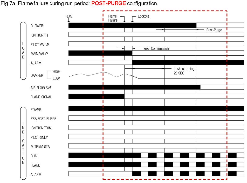
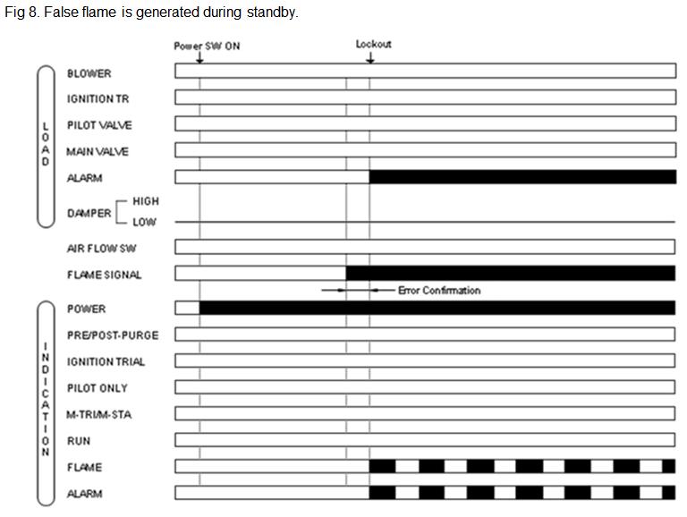
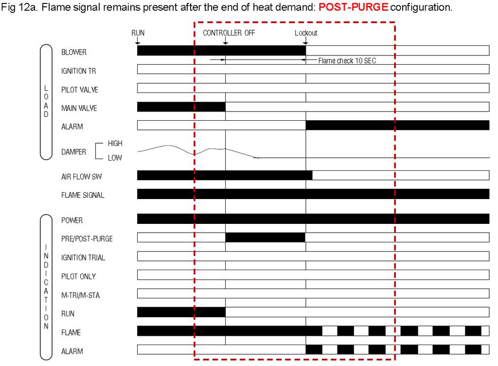
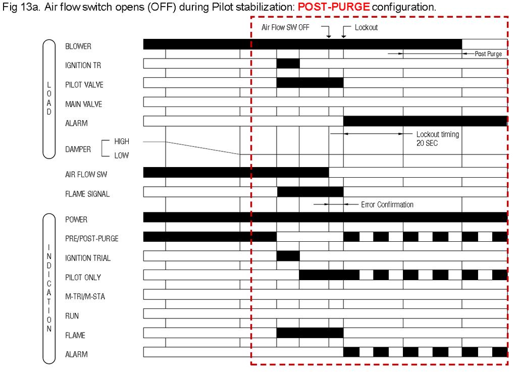
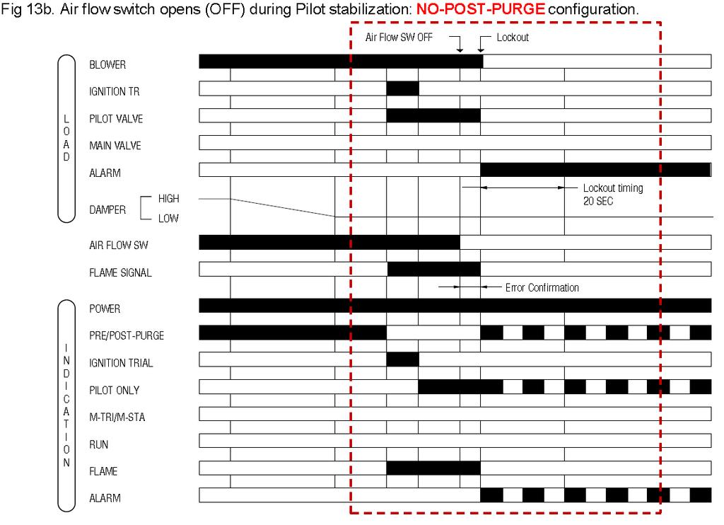
14 7. TROUBLE SHOOTING ERROR TYPES AND SAFE SHUTDOWN If a critical error related to safety operation (such as a loss of flame, opening of the air flow switch during the ignition trial and run sequence) is detected, the DBC2000 instantly goes into lock-out and goes to pre-purge status. If a non critical error is detected (such as opening of the air flow switch during post-purge), DBC2000 holds the sequence during the lock-out time, allowing time for the error to rectify, and then goes into lock- out. For all types of errors, the status LEDs indicate the status information to the operator. Fig. 6 to Fig. 13 show the sequence of DBC2000 in case of some error. And Table 8 shows the status of LEDs for each error. The product handbook (ENS7003) shows the different scenarios for possible failures. 14
15 15
16 16
17 17
18 18
19 19
20 20
21 21
22 Sequence All Standby (*2) Pre-purge Ignition Standby Pilot Ignition Pilot only Main ignition Main ignition Stabilization Run Post-purge Table 8: Error condition and LED status Error condition Safety limits opened at any time (no voltage present at T18 (STD model) or T19 (ENH/ULT model) Air flow switch remains ON (closed) for more than 5 minutes, or START position interlock switch remains OFF(opened) for more than 5 minutes. Flame signal is present Blower motor is energized Air flow switch remains OFF for more than 5 minutes after the heat demand has started. PURGE position interlock switch remains OFF for more than 5 minutes after the heat demand started. Both PURGE and START position interlocks ON at the same time during prepurge period START position interlock remains OFF more than 5 minutes after pre-purge has finished Air flow switch goes ON within 5 minutes after the heat demand started, but air flow switch goes OFF again. Flame signal is present. Air flow switch goes OFF Flame signal is present Air flow switch goes OFF Ignition failure (flame signal is not present after ignition-trial). Air flow switch goes OFF No flame signal Air flow switch goes OFF No flame signal Air flow switch goes OFF No flame signal Air flow switch goes OFF No flame signal No power is supplied to Terminal 3 because of internal relay contact failure. Flame signal is present for more than 10 seconds after heat demand has ended. Indicator LED status (*1) Air flow switch keeps ON more than 5 minutes after post-purge. 1. Line voltage out of specs for more than 2 seconds 2. Line frequency out of range for more than 2 seconds All 3. Excessive noise on power line or in the area 4. Internal device problem: CPU clock out of sync *1 : For LED indication, means off, means illuminated, means blinking. The LEDs are arranged in the following order: Standby, Purge, Ignition, Pilot, Main, Modulate, Flame and Alarm at the left front side of the DBC2000. *2 : If an error occurs during Standby, the DBC2000 will not lock-out but LEDs indicate the current error status. In this case, the DBC2000 cannot start before the error is resolved. 22
23 8. Approvals and Maintenance Declaration of Conformity Honeywell Technologies Sàrl Z.A. La Pièce Rolle Switzerland declares under it s sole responsibility that the following product family of burner controllers: DBC2000 E 1xxx / DBC2000 E 2xxx to which this statement relates, is: in conformity with the essential requirements of the Gas Appliance Directive 2009/142/EC based on EN 298 and in conformity with the type as described in the EC type-examination certificate issued by DVGW CERT GmbH in Bonn with pin number 0085CM0138 in conformity with the essential requirements of the Low Voltage Directive 2006/95/EC based on EN in conformity with the essential requirements of the EMC Directive 2004/108/EC on immunity based on EN 298 immunity requirements Conformity with the essential requirements of the EMC Directive 2004/108/EC on emission can only be determined in the application. This product is under surveillance at KIWA Nederland BV. Emmen, October 2011 Signed for and on behalf of Honeywell Technologies Sàrl, A.Veld Manager Standards & Approvals 23
24 Maintenance and service The designed lifetime* of this product is 10 years, based on date code, or cycles under normal conditions, according to: a) the standard EN 298 b) the table on designed lifetime as stated on the Afecor website We cannot assume that the product can be safely used beyond the mentioned designed lifetime. This lifetime is based on use of the control according manufacturer s instructions. Regular inspection of the control by authorized personnel in accordance with guidelines of the appliance manufacturer is required. After reaching the designed lifetime the product has to be replaced by authorized personnel. Note: * Warranty as opposed to designed lifetime is described in the delivery terms. 24
25 APPENDIX: Calculations for VPS General The maximum allowable leak-rate (according EN676 and EN746-2) is 0,1% of the maximum burner capacity. The test time necessary to detect a failing valve is a function of: - Inlet pressure - Test volume - Burner capacity When the volume between two safety valves is bigger it takes more time (in case of a leaking valve) to change the status of the gas pressure switch (GPS). The switching point of the GPS is set to 50% of the maximum inlet pressure. The test period Tp is calculated from the inletpressure Pi, the test volume Vp (see Table a.) and maximum burner capacity Qm. In a formula: Example 2 NOTE: to allow a 3-valve configuration, an external SPDT relay needs to be added, when used incombination with VPS. See schematic drawing below. 2 x Pi x Vp Tp = [s] Qm Pi = inlet pressure [mbar] Vp = test volume, see also Table a [dm 3 ] Qm = burner capacity [dm 3 /h] Tp = test time [s] Important The total volume Vp has to be calculated with all volumes between the tested valves: internal volumes of valves and all pipes. Calculation examples Example 1 Calculation of the minimum test time (per valve) in a 2 threaded pipe train. Pi = 150 mbar Qm = 60 dm 3 /h Gas valves used: 2 size with 0.5 meter pipe. To be calculated: Tp [s] Calculation: From Table a. : L=0.5m Vp = 2.3 dm 3 2 x 150 x 2.3 Tp = [s] 60 Using the formula above, the minimum test time Tp = 11.5s The DBC2000E2 must be set to 15s test time (see page 11). Calculation of the minimum test time (per valve) in a DN80 flanged pipe train, where a 1 bypass valve is used. Pi = 150 mbar Qm = 100 dm 3 /h Gas valves used: DN80 size with 1 meter pipe (L1). Bypass valve: 1 valve with 0.5 meter pipe (L2). To be calculated: Tp [s] Calculation: From Table a. : L1=1m Vp1 = 6.9 dm 3 L2=0.5m Vp2 = 0.44 dm 3 There is only 1 bypass valve, that reduces the total volume by 0.5x the L=0m Vp3 = 0.19 dm 3 Vp = Vp1 + Vp2 (0.5 x Vp3) = dm 3 2 x 150 x 7.15 Tp = [s] 100 Using the formula above, the minimum test time Tp = s The DBC2000E2 must be set to 25s test time (see page 11). 25
26 Table a. Volumes in dm3 for gas valves like Honeywell VE-series (Vp) with pipe length L (including V1 and V2). For combi blocks, like VQ-M series and direct linked valves, use the values shown under L=0m. Length between valves [m] Diameter per extra meter ¼ ½ ¾ ¼ ½ ½ DN DN DN Threaded connections: sizes in inches. Flanged connections: sizes in DN If L = 0m it means that valves are directly linked without pipe connections. Also applicable for combi-blocks (VQ-M series). 26
27 27
28 28
29 29
30 30
31 31
32 32
33 33
34 34
35 (Page intentionally left empty) 35
36 Honeywell Industrial Combustion Luchthavenlaan Vilvoorde Belgium 36
CORONA BURNER CONTROLLER INSTRUCTION MANUAL RCF15 EXCLUSIVE FOR FLAME ROD. Corona Corporation
 CORONA BURNER CONTROLLER INSTRUCTION MANUAL RCF15 EXCLUSIVE FOR FLAME ROD Corona Corporation This instruction manual contains important information for safe use of this device. Keep this instruction manual
Advanced Ultraviolet Burner Controller
 No. CP-SS-7E Advanced Ultraviolet Burner Controller Model AUR300C/AUR30C Overview The AUR300C Advanced Ultraviolet Burner Controller and AUR30C Advanced Ultraviolet Burner Controller with Communication
AUR300C, AUR350C. Advanced Ultraviolet Burner Controller
 No. CP-SS-7E Overview The AUR300C is a burner controller with a dynamic selfchecking function and is used in combination with the AUD300C or AUD00C Advanced Ultraviolet Flame Detector. This AUR300C controls
ELECTRONIC FLAME SUPERVISION MULTI-BURNER
 MULTI-BURNER MODEL: SENS-A-FLAME II Revision: 0 7112 DESCRIPTION Model 7112 Sens-A-Flame II is a second generation solid-state programmable combustion safeguard for supervising multiple burner ovens, furnaces,
Flame Safeguards LFE10. Building Technologies HVAC Products
 7 71 Flame Safeguards LAE LFE Flame safeguards for burners with intermittent operation The LAE is used for the supervision and indication of oil flames The LFE is used for the supervision and indication
LFL Series Burner Flame Safeguard Control
 LFL Series Burner Flame Safeguard Control Technical Instructions Document No. 74US LFL Rev. 2 November, 2004 The LFL is a compact electro-mechanical primary flame safeguard control designed to provide
SERIES VAC Microprocessor-Based Intermittent Pilot Ignition Control FEATURES APPLICATIONS SPECIFICATIONS DESCRIPTION
 R SERIES 35-703 120 VAC Microprocessor-Based Intermittent Pilot Ignition Control F-35-703 July 2016 FEATURES Safe start with DETECT-A-FLAME flame sensing technology Custom pre-purge and inter-purge timings
UV Flame Supervision System
 7 783 UV Flame Supervision System DETACTOGYR LFE50 Series 02 ISO 9001 The LFE50 is a self-checking UV flame supervision system designed for use with continuously operating burners or for burners running
R7120M 7800 SERIES Relay Modules
 R7120M 7800 SERIES Relay Modules INSTALLATION INSTRUCTIONS APPLICATION The R7120M are microprocessor-based integrated burner controls for automatically fired gas, oil, or combination fuel single burner
Flame Safeguards LFE10. Building Technologies HVAC Products
 7 71 Flame Safeguards LAE LFE Flame safeguards for burners with intermittent operation The LAE is used for the supervision and indication of oil flames The LFE is used for the supervision and indication
AUR300C. Advanced Ultraviolet Burner Controller
 No. CP-SS-1807E AUR300C Advanced Ultraviolet Burner Controller Overview The AUR300C is a burner controller with a dynamic selfchecking function and is used in combination with the AUD300C or AUD500C Advanced
Refer to Bulletin E-1101 for detailed information on the FLAME-MONITOR System.
 The Fireye EP260, EP270 (early spark termination), or EP265 (pilot stabilization) programmer modules are used with the FLAME-MONITOR Burner Management Control System (P/N E110). Several operational characteristics
DMG 973. Gas Burner Safety Control. For 2-stage forced draught and combi oil/gas burners, facility to connect an air damper unit
 A Honeywell Company Gas Burner Safety Control For 2-stage forced draught and combi oil/gas burners, facility to connect an air damper unit Possible flame detectors: - Ionisation probe - Infrared flicker
EUROFLAT SERIES TYPES C... S... M...
 EUROFLAT SERIES TYPES C... S... M... AUTOMATIC CONTROL SYSTEMS FOR GAS BURNERS AND GAS BURNING APPLIANCES WITH OR WITHOUT FAN APPLICATION The electronic systems of this range are suitable to control gas
SERIES VAC Microprocessor-Based Direct Spark Ignition Control FEATURES APPLICATIONS SPECIFICATIONS DESCRIPTION. Export Information (USA)
") R SERIES 35-70 120 VAC Microprocessor-Based Direct Spark Ignition Control F-35-70 November 2015 FEATURES Safe start with DETECT-A-FLAME flame sensing technology Custom pre-purge and inter-purge timings
R SERIES 35-70 120 VAC Microprocessor-Based Direct Spark Ignition Control F-35-70 November 2015 FEATURES Safe start with DETECT-A-FLAME flame sensing technology Custom pre-purge and inter-purge timings
LAE10 LFE10. Use. Series 02
 ISO 00 Flame Safeguards 7 7 LAE L Series 02 Supplementary data sheets 772 and 773 Flame safeguards for burners with intermittent operation. For safety reasons - self-test of flame supervision circuit,
EUROBOX SERIES TYPES CM...N SM...N MM...N
 EUROBOX SERIES TYPES CM...N SM...N MM...N AUTOMATIC CONTROL SYSTEMS FOR GAS BURNERS AND GAS BURNING APPLIANCES WITH OR WITHOUT FAN (MANUAL RESET) DESCRIPTION This series of electronic systems is suitable
SLATE. Burner Control Module INSTALLATION INSTRUCTIONS R8001B2001
 SLATE Burner Control Module R8001B2001 INSTALLATION INSTRUCTIONS Scan for more information Application SLATE brings configurable safety and programmable logic together into one single platform. The platform
RM7897A,C 7800 SERIES Relay Modules
 RM7897A,C 7800 SERIES Relay Modules INSTALLATION INSTRUCTIONS APPLICATION The RM7897A,C are microprocessor-based integrated burner controls for automatically fired gas, oil, or combination fuel single
SERIES VAC Microprocessor-Based Hot Surface Ignition Control FEATURES APPLICATIONS SPECIFICATIONS DESCRIPTION AGENCY CERTIFICATIONS
 SERIES 35-65 24 VAC Microprocessor-Based Hot Surface Ignition Control F-35-65 August 2015 FEATURES Safe start with DETECT-A-FLAME flame sensing technology Custom pre-purge and inter-purge timings* 120/240
INSTALLATION INSTRUCTIONS FOR SERIES 9 INTERMITTENT PILOT IGNITION CONTROL
 INSTALLATION INSTRUCTIONS FOR SERIES 9 INTERMITTENT PILOT IGNITION CONTROL Figure 1 Series 9 Intermittent Pilot Ignition Control Application The Series 9 Intermittent Pilot Ignition Control is a microprocessor
EUROBOX SERIES TYPES CM... SM... MM...
 EUROBOX SERIES TYPES CM... SM... MM... AUTOMATIC GAS BURNER CONTROL SYSTEMS FOR GAS BURNERS AND GAS BURNING APPLIANCES WITH OR WITHOUT FAN Application This range of electronic gas burner control systems
DMG 973. Gas Burner Safety Control. For 2-stage forced draught and combi oil/gas burners, facility to connect an air damper unit
 certified Qualitysystem ISO 9001 / EN 29001 Reg. Nr. 10529 Gas Burner Safety Control A Honeywell Company For 2-stage forced draught and combi oil/gas burners, facility to connect an air damper unit Possible
SERIES 35-63J APPLICATIONS FEATURES SPECIFICATIONS AGENCY CERTIFICATIONS
 SERIES 35-63J INSTALLATION INSTRUCTIONS FOR REPLACING JOHNSON CONTROLS G77X AND OTHER MODELS WITH FENWAL SERIES 35-63J IP IGNITION CONTROL APPLICATIONS The Fenwal 35-63J series Intermittent Pilot Ignition
50M Integrated Single or Two-Stage HSI Integrated Furnace Control Kit INSTALLATION INSTRUCTIONS
 50M56-743 Integrated Single or Two-Stage HSI Integrated Furnace Control Kit INSTALLATION INSTRUCTIONS FAILURE TO READ AND FOLLOW ALL INSTRUCTIONS CAREFULLY BEFORE INSTALLING OR OPERATING THIS CONTROL COULD
SERIES VAC Microprocessor-Based Direct Spark Ignition Control with Inducer Blower Relay FEATURES APPLICATIONS SPECIFICATIONS DESCRIPTION
 R SERIES 35-61 24 VAC Microprocessor-Based Direct Spark Ignition Control with Inducer Blower Relay F-35-61 August 2015 FEATURES Safe start with DETECT-A-FLAME flame sensing technology Custom pre-purge
Model 60200FR Gas Primary Control Data Sheet
 Programmable, Microprocessor Based Gas Burner Primary Controls On-Board LCD Screen Easy to Understand Icons for Inputs and Outputs Displays micro-amp Flame reading Display operational information Fault
DMG 970. Gas Burner Safety Control. For 2-stage forced draught and combi oil/gas burners
 certified Qualitysystem ISO 9001 / EN 29001 Reg. Nr. 10529 Gas Burner Safety Control A Honeywell Company For 2-stage forced draught and combi oil/gas burners Possible flame detectors: - Ionisation probe
FIREYE M4RT1 FLAME SAFEGUARD CONTROLS DESCRIPTION
 M-4000 JANUARY 29, 200 FIREYE M4RT1 FLAME SAFEGUARD CONTROLS WARNING: Selection of this control for a particular application should be made by a competent professional, licensed by a state or other government
Interrupted Ignition Series Oil Primary Control
 Interrupted Ignition Series Oil Primary Control Application Guide & Installation Instruction for ICM1511*, ICM1512*, ICM151*, ICM1514* For more information on our complete range of American-made products
RM7895A,B,C,D/EC7895A,C; RM7896A,B,C,D 7800 SERIES Relay Modules
 RM79A,B,C,D/EC79A,C; RM796A,B,C,D 700 SERIES Relay Modules INSTALLATION INSTRUCTIONS APPLICATION The RM79A,B,C,D/EC79A,C; RM796A,B,C,D are microprocessor-based integrated burner controls for automatically
LGA... Gas Burner Controls. Siemens Building Technologies HVAC Products
 7 418 Gas Burner Controls LGA... The LGA... are used for the startup and supervision of atmospheric gas burners of small to medium capacity (without fan) in intermittent operation. The LGA... and this
SLATE. Rectification Ampli-Check Flame Amplifier INSTALLATION INSTRUCTIONS R8001V1031
 SLATE Rectification Ampli-Check Flame Amplifier R8001V1031 INSTALLATION INSTRUCTIONS Scan for more information Application SLATE brings configurable safety and programmable logic together into one single
DKG 972. Gas Burner Safety Control. For 2-stage atmospheric gas burners
 certified Qualitysystem ISO 9001 / EN 29001 Reg. Nr. 10529 Gas Burner Safety Control A Honeywell Company For 2-stage atmospheric gas burners Flame detection: - Ionisation probe - Infrared-flicker detector
24 VAC Intermittent Pilot Gas Ignition Control
 C610U Universal 24 VAC Intermittent Pilot Gas Ignition Control Issue Date: 08/24/2016 Quick Reference Guide The C610U Universal Intermittent Pilot Gas Ignition Control module replaces many popular flame
Gas burner automatic safety control MMI / 811.1
 Gas burner automatic safety control MMI 810.1 / 811.1 For 2-stage forced draught and combi oil/ gas burners Possible flame detectors: - Ionization probe - Infrared flicker detector INTRODUCTION 0708.21-01-e/04/99
7800 SERIES RM7888A Relay Module
 7800 SERIES RM7888A Relay Module FEATURES SPECIFICATION DATA APPLICATION The Honeywell RM7888A Relay Module is a microprocessor-based integrated burner control for industrial process semi-automatically
7800 SERIES EC7895A,C; RM7895A,B,C,D and RM7896A,B,C,D Relay Modules
 7800 SERIES EC7895A,C; RM7895A,B,C,D and RM7896A,B,C,D Relay Modules SPECIFICATION DATA FEATURES APPLICATION The Honeywell EC7895/RM7895/RM7896 is a microprocessor based integrated burner control for automatically
7800 SERIES Relay Modules
 7800 SERIES Relay Modules CHECKOUT AND TEST This publication provides general checkout and troubleshooting procedures for the 7800 SERIES Relay Modules. SYSTEM CHECKOUT IMPORTANT Perform all Static Checkout
7800 SERIES: EC7895A,C; RM7895A,B,C,D; RM7896A,B,C,D RM7897A,C and RM7898A Relay Modules
 7800 SERIES: EC7895A,C; RM7895A,B,C,D; RM7896A,B,C,D RM7897A,C and RM7898A Relay Modules SPECIFICATION DATA The RM7897A1002 offers selectable pilot operation, intermittent on terminal 8 or interrupted
BGH Series Hot Surface Ignition Control
 Installation Instructions BGH Series Issue Date April 14, 2011 BGH Series Hot Surface Ignition Control Application The BASO Gas Products BGH Series Hot Surface Ignition (HSI) control is microprocessor
Operator: Save these instructions for future use!
 50V64-743 Integrated Furnace Control for Furnaces with Variable Fan Speed INSTALLATION INSTRUCTIONS Operator: Save these instructions for future use FAILURE TO READ AND FOLLOW ALL INSTRUCTIONS CAREFULLY
Operator: Save these instructions for future use!
 50A65-843 Universal Integrated Furnace Control INSTALLATION INSTRUCTIONS Operator: Save these instructions for future use! FAILURE TO READ AND FOLLOW ALL INSTRUCTIONS CAREFULLY BEFORE INSTALLING OR OPERATING
AUTOMATIC BURNER CONTROL SYSTEM SAFETY INFORMATION CONFORMITY
 AUTOMATIC BURNER CONTROL SYSTEM The burner control unit Quad400 is suitable for the control of direct ignition burners up to 350 kw, pursuant to EN 746-2. Flame control by means of UV scanner or ionization
Q7800H Integrated Burner Control Subpanel
 Q7800H Integrated Burner Control Subpanel INSTALLATION INSTRUCTIONS FEATURES Unique subpanel design eliminates extensive wiring in the OEM control panel. One subpanel design covers multiple applications.
SLATE. Base Module INSTALLATION INSTRUCTIONS R8001A1001
 SLATE Base Module R8001A1001 INSTALLATION INSTRUCTIONS Scan for more information Application SLATE brings configurable safety and programmable logic together into one single platform. The platform can
Operator: Save these instructions for future use!
 WHITE-RODGERS 50A55-474 & 50A55-571 Integrated Furnace Controls INSTALLATION INSTRUCTIONS Operator: Save these instructions for future use! FAILURE TO READ AND FOLLOW ALL INSTRUCTIONS CAREFULLY BEFORE
SLATE. UV Ampli-Check Flame Amplifier INSTALLATION INSTRUCTIONS R8001S1071
 SLATE UV Ampli-Check Flame Amplifier R8001S1071 INSTALLATION INSTRUCTIONS Scan for more information Application SLATE brings configurable safety and programmable logic together into one single platform.
Operator: Save these instructions for future use!
 031-01284-000/50A55-241 Integrated Furnace Control INSTALLATION INSTRUCTIONS Operator: Save these instructions for future use! FAILURE TO READ AND FOLLOW ALL INSTRUCTIONS CAREFULLY BEFORE INSTALLING OR
FIREYE FLAME SAFEGUARD CONTROLS DESCRIPTION
 SB-2301 SEPTEMBER 17, 2013 FIREYE FLAME SAFEGUARD CONTROLS WARNING: Selection of this control for a particular application should be made by a competent professional, licensed by a state or other government.
Operator: Save these instructions for future use!
 50A66-743 Integrated Furnace Control Operator: Save these instructions for future use! FAILURE TO READ AND FOLLOW ALL INSTRUCTIONS CAREFULLY BEFORE INSTALLING OR OPERATING THIS CONTROL COULD CAUSE PERSONAL
R7910A SOLA (Hydronic Control) and R7911 SOLA (Steam Control) Systems
 and R7911 SOLA (Steam Control) Systems") R7910A SOLA (Hydronic Control) and R7911 SOLA (Steam Control) Systems APPLICATION The R7910 SOLA hydronic boiler and the R7911 SOLA steam control systems provide heat control, flame supervision, circulation
R7910A SOLA (Hydronic Control) and R7911 SOLA (Steam Control) Systems APPLICATION The R7910 SOLA hydronic boiler and the R7911 SOLA steam control systems provide heat control, flame supervision, circulation
Instructions For A and Flame Simulators
 Instructions For 123514A and 203659 Flame Simulators Application Flame simulators are devices that simulate a flame by reproducing ultraviolet resistance or rectification characteristics of an actual flame.
MBCE-110/230UV Flame Sensor Module
 MBCE-1002 FEBRUARY 3, 2017 MBCE-110/230UV Flame Sensor Module DESCRIPTION The MBCE-110/230UV modules provide visual indication and electrical outputs that signal the user regarding flame presence in a
LFE50. UV Flame Safeguard. Building Technologies Division DETACTOGYR
 7 783 DETACTOGYR Flame Safeguard The... together with the QRA50M / QRA51M form a self-checking flame supervision system (DETACTOGYR ) designed for use with continuously operating oil or gas burners or
Operator: Save these instructions for future use!
 21M51U-843 Universal Integrated Two-Stage 120Volt Hot Surface Ignition Control Kit INSTALLATION INSTRUCTIONS Operator: Save these instructions for future use! FAILURE TO READ AND FOLLOW ALL INSTRUCTIONS
LGA... Gas Burner Controls. Siemens Building Technologies Landis & Staefa Division
 7 418 ISO 9001 Gas Burner Controls LGA... The LGA... are used for the startup and supervision of atmospheric gas burners of low to medium capacity, without fan assistance, in intermittent operation. The
Power Flame Incorporated
 Power Flame Incorporated SUGGESTED SPECIFICATION FOR MODEL NVC2 THRU NVC6 ULTRA LOW NOx GAS BURNERS SUB 9 PPM NOx WITH CONTROLINKS CONTROLS THE POWER TO MANAGE ENERGY 2001 South 21st Street, Parsons, Kansas
7800 SERIES RM7840E,G,L,M; EC7840L Relay Module
 7800 SERIES RM7840E,G,L,M; EC7840L Relay Module SPECIFICATION DATA Valve Proving features including: VPS test time When (Never, Before, After, Split or Both) FEATURES APPLICATION The Honeywell RM7840 is
LFE50. UV Flame Safeguard. Siemens Building Technologies HVAC Products DETACTOGYR. Series 02
 7 783 ISO 9001 DETACTOGYR Flame Safeguard Series 02 The... together with the QRA50M / QRA51M form a self-checking flame supervision system (DETACTOGYR ) designed for use with continuously operating oil
7800 SERIES EC7885A/RM7885A Relay Module
 7800 SERIES EC7885A/RM7885A Relay Module SPECIFICATION DATA 1. Torch-ignited main burner using the S445A Start-Stop Station, or any conventional knee or foot operated start-stop station. 2. Torch-ignited
LGA... Gas Burner Controls. Building Technologies Division
 7 418 Gas Burner Controls LGA... The gas burner controls are used for supervision, startup and control of atmospheric gas burners of small to medium capacity without a fan in intermittent operation. The
VeriFlame CE Burner Monitoring System
 Instruction Manual No. 818-2 9/02 VeriFlame CE Burner Monitoring System Model VF56 Version 2.0 COPYRIGHT DISCLAIMER NOTICE Copyright 2002 by Eclipse Combustion. All rights reserved worldwide. This publication
BC-R10 Series. Burner Controllers
 No. CP-SS-1885E BC-R10 Series Burner Controllers Summary BC-R10 Series burner controllers are combustion safety controllers specifically designed for batch operation (systems which start and stop at least
CAUTION WARNING. 50T Integrated Furnace Control INSTALLATION INSTRUCTIONS DESCRIPTION PRECAUTIONS
 50T35-743 Integrated Furnace Control INSTALLATION INSTRUCTIONS FAILURE TO READ AND FOLLOW ALL INSTRUCTIONS CAREFULLY BEFORE INSTALLING OR OPERATING THIS CONTROL COULD CAUSE PERSONAL INJURY AND/OR PROPERTY
YP7999A1000 ControLinks Fuel Air Ratio Control Panel
 YP7999A1000 ControLinks Fuel Air Ratio Control Panel FEATURES INSTALLATION INSTRUCTIONS Pre-wired and ready to install Includes the R7999A control, wiring subbase and S7999D1048 touchscreen display Commission,
BURNER MANAGEMENT CONTROLS
 HEATEC TEC-NOTE SCOPE This document applies to burner management controls used on Heatec Firestorm water heaters (Fig. 1). It only covers controls of Firestorm heaters in current production. Some earlier
Model Universal Oil Primary Control
 Model 70200 Universal Oil Primary Control Installation and Operating Instructions For Use By Qualified Service Technicians Only Universal Replacement for Carlin, Beckett, Honeywell and ICM Controls On-Board
R7910A SOLA (Hydronic Control) and R7911 SOLA (Steam Control) Systems
 and R7911 SOLA (Steam Control) Systems") R7910A SOLA (Hydronic Control) and R7911 SOLA (Steam Control) Systems INSTALLATION INSTRUCTIONS APPLICATION The R7910 SOLA hydronic boiler and the R7911 SOLA steam control systems provide heat control,
R7910A SOLA (Hydronic Control) and R7911 SOLA (Steam Control) Systems INSTALLATION INSTRUCTIONS APPLICATION The R7910 SOLA hydronic boiler and the R7911 SOLA steam control systems provide heat control,
EURO-OIL SERIES TYPES G.. G../. OR.. OR../. F.. FR..
 EURO-OIL SERIES TYPES G.. G../. OR.. OR../. F.. FR.. AUTOMATIC OIL BURNER CONTROL SYSTEMS APPLICATION This range of electronic oil burner controls has been specifically designed for oil burners for non
50A Integrated Furnace Control
 Goodman White-Rodgers 0130F00005 PCBBF110 PCBBF123 50A55-743 0130F00005S PCBBF110S PCBBF123S 50A55-289 B1809926 PCBBF112 50T55-289 B1809926S PCBBF112S 50A55-743 Integrated Furnace Control INSTALLATION
24 VAC Direct Spark Gas Ignition
 Installation Instructions Issue Date March 3, 2017 Quick Reference Guide The Direct Spark Gas Ignition control module is designed for direct burner ignition and supervision. It can be used in new applications
50M56U-843 Universal Single Stage HSI Integrated Furnace Control Kit INSTALLATION INSTRUCTIONS
 50M56U-843 Universal Single Stage HSI Integrated Furnace Control Kit INSTALLATION INSTRUCTIONS INSTALLER MUST READ PAGE 3 CONTAINS WIRING HARNESS AND BLOWER CONNECTION INSTRUCTIONS FOR ALL APPLICATIONS
Operator: Save these instructions for future use!
 WHITE-RODGERS 50A55-286 Integrated Furnace Control INSTALLATION INSTRUCTIONS Operator: Save these instructions for future use FAILURE TO READ AND FOLLOW ALL INSTRUCTIONS CAREFULLY BEFORE INSTALLING OR
Forced draught gas burner
 Installation, use and maintenance instructions Forced draught gas burner Code Model Type 3751982 GAS 3 519T80 291 (3) - 02/2010 DECLARATION Declaration of conformity in accordance with ISO / IEC 17050-1
50M56U-843 INSTALLER MUST READ DESCRIPTION PRECAUTIONS WARNING CAUTION
 50M56U-843 Universal Single Stage HSI Integrated Furnace Control Kit INSTALLATION INSTRUCTIONS INSTALLER MUST READ PAGE 3 CONTAINS WIRING HARNESS AND BLOWER CONNECTION INSTRUCTIONS FOR ALL APPLICATIONS
7800 SERIES RM7888A Relay Module
 7800 SERIES RM7888A Relay Module SPECIFICATION DATA FEATURES APPLICATION The Honeywell RM7888A Relay Module is a microprocessor-based integrated burner control for industrial process semi-automatically
Oil Burner Controls LMO24... LMO44...
 7 130 Oil Burner Controls LMO14... LMO24... LMO44... Microcontroller-based oil burner controls for the startup, supervision and control of forced draft oil burners in intermittent operation. Standard versions
DKO 974/976 DKO 974 N/976 N. Oil Burner Safety Control
 Oil Burner Safety Control A Honeywell Company DKO 974 N/976 N For 1- or 2-stage oil burners up to 30 kg/h throughput and intermittent operations with or without oil preheating Flame detection: - Photoresistor
RM7895A,B,C,D/EC7895A,C; RM7896A,C,D 7800 SERIES
 RM7895A,B,C,D/EC7895A,C; RM7896A,C,D 7800 SERIES Relay Modules INSTALLATION INSTRUCTIONS APPLICATION The RM7895A,B,C,D/EC7895A,C; RM7896A,B,C,D are microprocessor-based integrated burner controls for automatically
LMV51 Control. Specifications. Document No. LV February 7, Product Description. Sample Specification
 SCC Inc. LMV51 Control Product Description February 7, 2017 The LMV51 is a microprocessor-based burner management system with matching system components for the control and supervision of forced draft
T8190A/191108AJ Heating or Cooling Thermostat/Wallplate; T8190A/Q682B Heating/Cooling Thermostat/Subbase
 M3375 M3375 T890A/908AJ Heating or Cooling Thermostat/Wallplate; T890A/Q68B Heating/Cooling Thermostat/Subbase Installation Instructions for the Trained Service Technician. Preparation NOTE: Order Q68B
50A Integrated Furnace Control
 50A56-956 Integrated Furnace Control INSTALLATION INSTRUCTIONS FAILURE TO READ AND FOLLOW ALL INSTRUCTIONS CAREFULLY BEFORE INSTALLING OR OPERATING THIS CONTROL COULD CAUSE PERSONAL INJURY AND/OR PROPERTY
Oil Burner Controls LMO24... LMO44...
 7 130 Oil Burner Controls LMO14... LMO24... LMO44... Microcontroller-based oil burner controls for the startup, supervision and control of forced draft oil burners in intermittent operation. Standard versions
RM7838A 7800 SERIES Relay Modules
 RM788A 7800 SERIES Relay Modules APPLICATION The Honeywell RM788A is a microprocessor-based integrated burner control for semi-automatically fired gas, oil, or combination fuel single burner applications.
Quick Reference Guide. Application. Gas Furnaces Boilers Water Heaters Commercial Cooking. Features
 Installation Instructions E14QRG Issue Date June 28, 2018 Quick Reference Guide The Direct Spark Gas Ignition control module is designed for direct burner ignition and supervision. It can be used in new
LMV52 Control. Specifications. Document No. LV February 3, Product Description. Sample Specification
 LMV52 Control Product Description February 3, 2017 The LMV52 is a microprocessor-based burner management system with matching system components for the control and supervision of forced draft burners.
7800 SERIES EC7890A,B; RM7890A,B,C Relay Module
 7800 SERIES EC7890A,B; RM7890A,B,C Relay Module SPECIFICATION DATA EC7890 APPLICATION RM7890 The Honeywell EC7890A,B/RM7890 is a microprocessor based integrated burner control for automatically fired gas,
Flame Safeguard Fault Code Diagnostics
 Vino s Vine Tech Tips Series 02/2013 Flame Safeguard Fault Code Diagnostics As manager of Tech Services, it probably comes as no surprise I spend some time discussing fault codes and corresponding corrective
Honeywell Primary Control Cross Reference
 Honeywell Primary Control Cross Reference Page Pages, Page, Page Page Page Pages 9, 0 Page Pages, Page Pages, Page Page Pages 9,0 R, R0, R, R90B, RA90B, R90C, R, R90B RA90B, R90C, RA90C, RA90XB,XC, RA90D
Power Flame Incorporated
 Power Flame Incorporated SUGGESTED SPECIFICATION FOR MODEL NVC ULTRA LOW NOx GAS BURNERS SUB 9 PPM NOx THE POWER TO MANAGE ENERGY 2001 South 21st Street, Parsons, Kansas 67357 Telephone: 620-421-0480,
7800 SERIES RM7840E,G,L,M Relay Module
 7800 SERIES RM7840E,G,L,M Relay Module APPLICATION SPECIFICATION DATA The Honeywell RM7840 is a microprocessor based integrated burner control for automatically fired gas, oil or combination fuel single
LOA2... LOA3... Oil Burner Controls. Siemens Building Technologies Landis & Staefa Division
 7 8 ISO 900 LOA2... LOA... Oil Burner Controls LOA2... LOA... Oil burner controls for the supervision, startup and control of single- or twostage oil burners with an oil throughput of up to 0 kg/h in intermittent
E110 FIREYE FLAME-MONITOR BURNER MANAGEMENT CONTROL FOR USE WITH THE MICROPROCESSOR-BASED EP AND EPD STYLE PROGRAMMER MODULES
 E-11 MARCH 28, 2013 E1 FIREYE FLAME-MONITOR BURNER MANAGEMENT CONTROL FOR USE WITH THE MICROPROCESSOR-BASED EP AND EPD STYLE PROGRAMMER MODULES E1 with ED5 Display Module APPROVED DESCRIPTION The Fireye
R7824, R7847, R7848, R7849, R7851, R7852, R7861, R7886 Amplifiers for 7800 SERIES and R7140 Relay Modules
 R7824, R7847, R7848, R7849, R7851, R7852, R7861, R7886 Amplifiers for 7800 SERIES and R7140 Relay Modules PRODUCT DATA indicate the presence of flame when used with 7800 SERIES and R7140 Relay Modules.
prestige Condensing Water Boiler SERVICE TECHNICIAN S TROUBLE SHOOTING GUIDE TSG-SOLO-9/04
 prestige Condensing Water Boiler SERVICE TECHNICIAN S TROUBLE SHOOTING GUIDE 2004-28 TSG-SOLO-9/04 Table of Contents INTRODUCTION Page 1 SERVICING TIPS AND INSTRUCTIONS Page 3 CONTROL MODULE DISPLAY -
MICROFLAT SERIES TYPES C.../U T X
 MICOFLAT SEIES TYPES C.../U T X AUTOMATIC GAS BUNE CONTOL SYSTEMS FO GAS BUNES AND GAS BUNING APPLIANCES WITH O WITHOUT FAN APPLICATION This range of electronic gas burner control systems is suitable for
DATASHEET. Burner control unit FDA 601x
 EN 298 / EN 230 2012 19 PCB 100x160mm 3HE/8TE socket DIN 41612 2-channel microprocessor controlled program air valve control for heating / cooling preventilation continuous operation with ionisation intermittent
7800 SERIES EC7810A, EC7820A Relay Module
 7800 SERIES EC780A, EC780A Relay Module PRODUCT DATA GENERAL The Honeywell EC780A or EC780A Relay Module is a microprocessor based integrated burner control for automatically fired gas, oil, or combination
UV Scanner. Model Specification. Introduction. 854 Instruction Manual
 854 Instruction Manual 10/11/010 UV Model 5600-91 C US Introduction This sensor features a high temperature and high sensitivity ultraviolet (UV) tube for monitoring gas or oil flames in applications that