Instruction manual. Analyt 2 / Analyt 3
|
|
|
- Abigayle White
- 6 years ago
- Views:
Transcription

1 Instruction manual Measurement, control and dosing device for swimming pools Analyt 2 / Analyt 3 1
2 Contents 1 OVERVIEW Analyt 2 and Analyt Maintenance program Overview of features INSTALLATION Wall installation Installation in the pumping system OPERATION Operating principles Commissioning menu SOFTWARE Schematic diagram of menu structure PH CONTROL View in the home display ph control configuration CHLORINE (CL) CONTROL View in the home display Chlorine control configuration MV (REDOX) MEASUREMENT (ANALYT 3 ONLY) View in the home display mv (redox) measurement configuration TEMPERATURE MEASUREMENT View in the home display Temperature configuration ALARM MONITORING Overview Flow alarm Power-on delay Alarm signalling Blocking of dosing by alarms Overview table Alarm settings SERVICE MESSAGES Overview Signalling of due service messages Re-planning of service messages EVENT LOG Overview MANUAL DOSING Overview...32 "Manual Dosage" menu Blocking by alarms Special case of shock chlorination Special case of pump test (ph / Cl) PLUG-IN MODULES
3 13.1 Universal switch outputs Relays Current outputs 0/ ma PM4Comm PC communication package PoolConnect (remote maintenance via SMS) EXTERNAL CONNECTIONS Signal terminals (green terminal block, left) Line voltage terminals 230 VAC (black terminal block, right) Standard wiring (without plug-in options) ANALYT INTERIOR Frontprint...42 Back PCB TROUBLESHOOTING AND FAULT ELIMINATION SPARE PARTS AND OPERATING MATERIALS FOR ANALYT 2/3: Spare parts for Analyt 2/ Operating materials for Analyt 2/ Options for Analyt 2/
4 Danger: Note: The dosing fluids used are corrosive and / or inflammable. Never allow the two ends of the delivery hoses on the vacuum pumps to hang loose, as this will permit the corrosive and/or inflammable fluids to escape. Always observe the relevant health and safety regulations when installing and using the device. It must only be installed and operated by qualified expert personnel. It must only be installed and put into operation by qualified technicians. WARNING Changing the system settings (default values) can be dangerous under certain circumstances. Therefore, changes must only be made by trained technicians. The operator assumes liability if settings are used improperly or modified. Note: The use of other products such as hydrochloric acid to control the ph value can quickly result in serious damage. BAYROL recommends that the device be operated with BAYROL products only. BAYROL does not provide a guarantee or accept liability for problems caused by using other manufacturers' products. Do not touch the screen of the device with anything else but the finger. Any contact with other objects such as pens, knives or nails may cause scratches or other damages of the surface. Any damage caused by misapplication will result in loose of warranty! Password for customer level : Password "1234" (if not set differently on the factory level) 4
5 1 Overview 1.1 Analyt 2 and Analyt 3 The Analyt is a highly advanced measurement, control and dosing system for public and private swimming pools. Analyt 2 and Analyt 3 are in accordance with DIN Maintenance program Two types of device are available in the Analyt series; these can be enabled by simply configuring the software using the ident chip: 1. Analyt 2 Water treatment by chlorine dosing Measurement and control of the chlorine level Measurement and control of the ph level Measurement of the water temperature 2. Analyt 3 Water treatment by chlorine dosing Measurement and control of the chlorine level Measurement and control of the ph level Measurement of the redox level Measurement of the water temperature 1.3 Overview of features Independent of the type of device, each controller provides the following features: Display and operation High resolution 5.7 screen, monochrome, blue background lighting Simple operation via touch screen Clear menu structure Menus can be changed to multiple different languages Screen with automatic switch-off to save energy (adjustable) Online help 5
6 1.3.2 Measuring and control Proportional control for all control modules All important control parameters can be programmed individually for each control module (setpoint, maximum dosing time, proportional range, dead zone (ph), basic dose (mv), dosing period, minimum switch-on/switch-off time Continuous display of current dosing rate Conversion of all measurements by high resolution 10-bit analogue/digital converters 1- or 2-point calibration for ph measurements 1-point calibration of mv and T measurements Safety functions Comprehensive monitoring and alarm functions (upper and lower threshold alarms, flow alarm, level alarms, dosing time alarms, calibration time alarms, battery alarm, power-on delay, automatic blocking of dosing during critical alarm conditions and during power-on delay, alarm notification through display acoustic alarm signal alarm relay continuous monitoring of the correct program sequence and automatic reset in the event of an error (watchdog function) PC communication (CommLink) Optional PC communication via an RS-485 interface with logging, storage and graphic display of all relevant measurements, remote operation of the Analyt device (several devices can be connected to a single PC) PoolConnect Optional use of PoolConnect. PoolConnect is a GSM module used to communicate with Analyt. PoolConnect automatically provides information on the water quality. 6
7 2 Installation The Analyt measurement, control and dosing device is a precise and sensitive system. Please handle it with care at all times. Also be careful with the cover and do not let it drop or come into contact with chemicals. If the cover requires cleaning, always use a soft cloth and a small amount of water. 2.1 Wall installation Firmly install the Analyt mounting plate on a wall. The installation site should be protected against dust and water as far as possible to ensure that the device functions properly. The ambient temperature should lie between -0 C and + 50 C and should be relatively constant. Direct solar and heat radiation onto the device should be avoided. In addition, the installation site should be close to where the measurement water is drawn. Please be careful to ensure that the amperometric measurement cell is horizontally positioned. 2.2 Installation in the circulation system Perform all installation work carefully and comply with the applicable safety regulations. Disconnect the measurement, control and dosing device and all other electrical loads such as heating or circulation pump from the mains. In addition, comply with the applicable regulations regarding the installation of electrical devices. The earthing provided for the plexiglass measurement chamber MUST be installed. This earthing should NOT be connected in the Analyt (earthing via the power cable of the Analyt) but MUST be connected to a separate safe earthing. Make sure that the earthing is functioning properly. Always ensure that fault current is not flowing into the water of the swimming pool. Professional measurement is recommended. General notes on installation: Please ensure that the injection locations can opened and closed reliably. Ensure that all hoses are laid without kinking. Avoid laying the hoses over sharp edges. Carefully connect all hoses and check that all connections are firmly attached. Avoid unnecessarily long hose lengths. Do not guide the hoses directly over warm pipes or systems. When connecting the dosing pumps, please follow the operating and installation instructions of each unit. Regularly check that the float in the measurement chamber can float freely. Adjust the water flow through the cell so that there is a gap of about 1-2 mm between the top edge of the float and the top edge of the proximity switch. (See figure.) 7
 IMPORTANT: Always connect the earthing screw on the bottom of the measuring chamber with a reliable building earth.")
8 If you are using a Flockmatic pump for dosing of Quickflock Automatic, connect it to one of the connections controlled by the circulation pump (circulation OFF flocculation OFF; circulation ON flocculation ON) IMPORTANT: Always connect the earthing screw on the bottom of the measuring chamber with a reliable building earth. Do NOT connect earth in the controller housing! 8


9 3 Operation 3.1 Operating principles Touchscreen The touch screen is a high resolution screen with blue background lighting that responds to finger pressure. Please note that light pressure is fully adequate to achieve the desired reaction. Although the screen is very robust and long-lived, please ensure that it is not scratched and that it does not come into contact with corrosive fluids (e.g. ChloriLiquid, ph plus/minus, etc.). To clean the screen, use a mild cleaner on a soft cloth. Always wipe it with a damp Normal display of Analyt 3 cloth after cleaning. In the normal display shown here, the screen is not pressure sensitive and settings cannot be changed accidentally. Do not touch the screen of the device with anything else but the finger. Any contact with other objects such as pens, knives or nails may cause scratches or other damages of the surface. Any damage caused by misapplication will result in loose of warranty! Direct selection buttons Menu button To change from the normal display to the selection of further menus. These are: Main menu (customer) Main menu (service) Alarms Service messages Contrast setting Operating mode (automatic/off) Esc button To return to the preceding menu. Note : Changes are not saved. Home button To change back to the normal display from any menu page. Help button To display context-sensitive help on the current menu. 9
 can")


10 3.1.3 Entering data Entries or changes are very easy to make and always involve the same steps. In general: Any value or term surrounded by a white frame or inverted (blue type in white box) can be changed. If you wish to make a change, lightly touch the area within the frame on the screen with your finger. The display responds by opening the menu page with the desired content. The method used to make an entry is illustrated in the following example, which shows how to change the ph setpoint: Open the Select the main menu (customer) Enter 1234 OK Select the "Measuring & Control menu 10
 using the numerical keypad that appeared and confirm with \"OK\" The new ph value is accepted (in this case, e.g. 7.4 ph) You can now close the page step-by-step by pressing Esc (e.g. to make further changes in other menus) or return to the normal display directly using the Home button A context-sensitive help is available for every displayed menu page.")

11 Select the "ph" menu Select the ph setpoint by placing your finger within the frame next to the term Enter the desired ph setpoint (e.g. ph 7.4) using the numerical keypad that appeared and confirm with "OK" The new ph value is accepted (in this case, e.g. 7.4 ph) You can now close the page step-by-step by pressing Esc (e.g. to make further changes in other menus) or return to the normal display directly using the Home button A context-sensitive help is available for every displayed menu page. It can be opened by simply touching the Help button Detailed online help An important component of the Analyt software is the detailed online help. It is context-sensitive and offers additional assistance on every menu item. Thus this manual is not essential for normal operation of the Analyt since all important information is contained in the software and can be accessed by pressing the Help button. 11
12 3.2 Commissioning menu Analyt has a menu for use in commissioning the system. All parameters that are relevant to successfully installing the equipment can be set in this menu. Despite the fact that this menu greatly facilitates commissioning, the procedure may only be performed by qualified technicians. All parameters to be set must be checked carefully. The conditions in and around the pool must be evaluated professionally and considered when programming the device. The menu for commissioning appears when the device is first switched on. It can also be opened at any time using the Service Functions menu item in the main menu (service). The following parameters can be set: Action Step 1: Language Select the menu language Enter Step 2: Setting default parameters The default value set to be used can be selected here. Step 3: Pool parameters Set up the pool and system parameters Step 4: Calibration Calibrate (balance) the ph, Cl and redox (Analyt 3 only) measurements Step 5: Control parameters ph Set up the main parameters for ph control Step 6: ph adjustment Option to automatically/manually adjust the ph value of the pool water Step 7: Manual dosage Cl Adjust the correct chlorine content in the pool water Select the location where the device is used. If unsure, check and change, if necessary, all default values to ensure they are correct for the respective installation. For added security, activation of the default values must be confirmed. Volume of connected swimming pool Hose configuration of the employed pump hoses. This display is used for monitoring. The settings are made at the factory for the respective device configuration. 1-point calibration for ph. Please proceed as described in this manual or in the help text in the device. 1-point calibration for Cl. Please proceed as described in this manual or in the help text in the device. 1-point calibration for mv. Please proceed as described in this manual or in the help text in the device. When the pool is refilled, it may be useful to extend the upper and lower thresholds of the ph value and to adjust the p-range since the ph value may fluctuate somewhat in the run-in phase. ATTENTION: If you adjust the parameters, ensure that the values are returned to their standard settings after the pool water has stabilised. The set ph setpoint and the current ph value of the pool water are displayed. NOTE: The ph value of the pool water must be adjusted to ph 7.2 to ensure that the redox values can be adjusted correctly. 1. Set the ph operating mode to Auto if Analyt is to make the adjustment automatically. The time the procedure takes depends on the pool size and the water quality. 2. Set the operating mode to Manual if you want to adjust the ph value by manually adding agents that raise or lower the ph value. To adjust the chlorine content to the desired value (setpoint), proceed as follows: 12
13 Step 8: Control parameters Cl Set up the main parameters for chlorine control 1. Adjust the ph value to ph 7.2 (see previous step) 2. Using manual dosage (or by adding chlorine manually), adjust the chlorine content to approx mg/l (value recommended in Germany) in the pool water. The dose amount of ChloriLiquid is determined by Analyt on the basis of the pool volume entered. The quantity can be overwritten manually and adapted. Set the chlorine content to mg/l. Adjust the lower and upper alarm thresholds accordingly. Check the p-range. From each individual menu page, you can leaf forward and backward through the pages. 4 Software Menu structure All menus and parameters in the software can be accessed on two levels. The "Main menu (customer)" access level (code no. "1234") displays all menu items and parameters relevant to the user. The "Main menu (service)" access level (code no. "5678") displays all menu items and parameters contained in the software. The "Entry menu", which appears immediately after the menu button is touched, is not protected by a code number and offers rapid and simple access to certain basic Analyt functions: Alarms Displays all current alarms. Service messages Displays all current service messages. Contrast setting For adjusting the display contrast to an optimal level. Operating mode (automatic/off) For switching the automatic dosage mode on and off. In the "Off" setting, the dosing pumps are switched off. Dosing does not take place. AS A RULE, THE PARAMETERS IN THIS MENU MAY ONLY BE CHANGED BY QUALIFIED AND TRAINED TECHNICIANS! 13


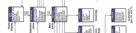
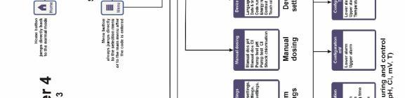
14 4.2 Schematic diagram of menu structure 14
15 5 ph control 5.1 View in the home display Pos. Content Remarks 1 Module name "ph" 2 Current ph measurement value ph 3 Measurement graphic See description below 4 Current operating state Auto / Off / Manual / Alarm (flashes!) / Flow / Power-on delay ("x min") 5 Pump symbol The pump symbol rotates when the pump it represents is running. Current dosing direction D- / D+ Current dosing rate ph 6 Alarms All active alarms that pertain to the ph module are displayed. Alarms whose cause has been eliminated disappear from the display even if they have not yet been quit. If there are no active alarms, "OK" appears Measurement graph The measurement graph shows the relationship between the current measurement value, the upper and lower threshold limits and the setpoint at a glance. The graphic represents the area between the upper and lower thresholds. It is easy to discern whether the current measurement value agrees with the desired setpoint or if the value lies within the threshold limits. 15

16 5.2 ph control configuration Setpoint, limits, p-range The ph control can be configured in the Commissioning menu or in the Customer menu under Measuring & Control (expanded parameter set) as described here. ph control settings Parameter Setpoint ph Lower Alarm ph Upper Alarm ph Max. Dos. Time ph p-range ph Min. On-time Purpose / effect The desired ph value of the swimming pool water. It is recommended that you aim for a ph value of 7.2 since water disinfection is most effective at this level. The lower alarm threshold of the ph value. As soon as the ph value falls below the entered level, an alarm is output. The lower limit should lie 0.4 ph below the setpoint. The upper alarm threshold of the ph value. As soon as the ph value rises above the entered level, an alarm is output. The upper limit should lie 0.4 ph above the setpoint. The maximum duration for which an agent to raise or lower the ph value is dosed. If the set time is exceeded, an alarm is output and dosing of the agent is stopped. The p-range setting. The p-range defines the response speed of the controller. As a rule: The smaller the percentage, the more product will be dosed. Advantage: the setpoint can be reached quickly. Disadvantage: the setpoint may not only be reached but may actually be exceeded. The larger the percentage, the less product will be dosed. Advantage: the setpoint is reached and is not exceeded. Disadvantage: the setpoint is reached more slowly. Minimum time for which the dosing pump is switched on. If the current deviation of the ph value requires a dosing time that is less than the set on-time, dosing still takes place for the set on-time. The country-specific default values for the individual parameters are provided in the country list in the appendix. 16
17 5.2.2 ph electrode calibration The Analyt ph electrode must be calibrated once every three months to compensate for any deviations in its measurement behaviour. The electrode must be replaced once a year. These maintenance and replacement intervals absolutely must be complied with to ensure that measurements are correct and that water quality is at its best. As an example, the procedure for a 1-point calibration of the ph electrode is described here. The 1-point calibration takes place in the main menu (customer). In this menu, select the Measuring & Control menu followed by the Calibration menu. Procedure for the 1-point ph calibration: Dip the ph electrode in a buffer solution of ph 7. Wait until Current Value ph stabilises and remains constant. Under Cal. Value, enter 7.00 and confirm with "OK". Touch Next to start the calibration. The page that now appears shows the Electrode Slope and Offset parameters (zero shift). Although it is possible to adjust these values here, they do not need to be changed. Touch Ready to complete the calibration. Alternatively, proceed as follows: Take a water sample from the pool and determine its ph value using a photometer. The measured value should lie around ph 7 to ensure that calibration will be correct. Dip the electrode into the measured sample. Wait until Current Value ph stabilises and remains constant. Under Cal. Value, enter the measured value and confirm with "OK". Touch Next to start the calibration. The page that now appears shows the Electrode Slope and Offset parameters (zero shift). Although it is possible to adjust these values here, they do not need to be changed. Touch Ready to complete the calibration. 17

18 Parameter Purpose Setting Calibration Parameters ph ph Electrode Slope of ph electrode Not required because this is an electrode constant Offset ph Zero shift of ph measurement Not required because this is compensated by the calibration 1-Point Calibration ph Calibration Data Cal. Value ph ph reference value for calibration ph 7 if using the buffer solution ph value of water sample Current Value ph Display of ph value currently measured Not possible ph Electrode Slope of ph electrode Not required Current Signal ph 1-Point Calibration ph Calibration Results Current deviation of ph measurement signal 7.00 if using the buffer solution ph value obtained from photometer Not possible ph Electrode Slope of ph electrode Not required Offset ph Calculated offset ph Not required Current Value ph Display of ph value currently measured Not possible 18
19 6 Chlorine (Cl) control 6.1 View in the home display Pos. Content Remarks 1 Module name "Cl" 2 Current chlorine measurement value (free chlorine) mg/l 3 Measurement graphic For a description, see "ph control" 4 Current operating state Auto / Off / Manual / Alarm (flashes!) / Flow / Power-on delay ("x min") 5 Pump symbol The pump symbol rotates when the chlorine dosing pump is running. Current dosing direction D+ / D- Current dosing rate % (a dosing rate of 50% means that the dosing pump is running 50% of the time) 6 Alarms All active alarms that pertain to the Cl (chlorine) module are displayed. Alarms whose cause has been eliminated disappear from the display even if they have not yet been quit. If there are no active alarms, "OK" appears. 19

20 6.2 Chlorine control configuration Setpoint, limits, p-range The chlorine control can be configured in the Commissioning menu or in the Service menu under Measuring & Control (expanded parameter set) as described here. Chlorine control settings Parameter Setpoint Cl Lower Alarm Cl Upper Alarm Cl Max. Dos. Time Cl p-range Cl Min. On-time Purpose / effect The desired chlorine value of the swimming pool water. The default value is 0.65 mg/l. The lower alarm threshold of the chlorine value. As soon as the chlorine value falls below the entered level, an alarm is output. The upper alarm threshold of the chlorine value. As soon as the Cl value rises above the entered level, an alarm is output. The maximum duration for which chlorine is dosed. If the set time is exceeded, an alarm is output and dosing of chlorine is stopped. If the maximum dosing time is set to 0, it is deactivated. The p-range setting. The p-range defines the response speed of the controller. As a rule: The smaller the percentage, the more product will be dosed. Advantage: the setpoint can be reached quickly. Disadvantage: the setpoint may not only be reached but may actually be exceeded. The larger the percentage, the less product will be dosed. Advantage: the setpoint is reached and is not exceeded. Disadvantage: the setpoint is reached more slowly. Minimum time for which the dosing pump is switched on. If the current deviation of the chlorine value requires a dosing time that is less than the set on-time, dosing still takes place for the set on-time. 20
21 Chlorine control settings (continued) Parameter Basic Dose Cl Dead Zone Cl Dos. Period Cl Dos. Direction Cl Purpose / effect Constant dosing rate that is always added to the calculated dosing rate. The basic dose can be set in the range of 0%-50%. Chlorine range surrounding the setpoint within which a setpoint deviation does not trigger a chlorine dosing. Fixed duration of a dosing cycle. The dosing cycle is the sum of the switch-on and switch-off time. Dosing direction of chlorine control: D+ : Chlorine value is raised when dosing (default) D- : Chlorine value is lowered when dosing Calibration of chlorine measurement cell The Analyt chlorine measurement cell must be calibrated once every three months to compensate for any deviations in its measurement behaviour. The electrodes must be replaced at least every two years and sometimes far more frequently if wear is excessive. These maintenance and replacement intervals absolutely must be complied with to ensure that measurements are correct and that water quality is at its best. As an example, the procedure for a 1-point calibration of the chlorine measurement cell is described here. The 1-point calibration takes place in the main menu (customer) or in the main menu (service). In this menu, select the Measuring & Control menu followed by the Calibration menu. Procedure for the 1-point chlorine calibration: Record the content of free chlorine using DPD measurement. Wait until Current Value Cl stabilises and remains constant. Under Cal. Value, enter the measured DPD value and confirm with "OK". Touch Next to start the calibration. The page that now appears shows the Electrode Slope and Offset parameters (zero shift). Although it is possible to adjust these values here, they do not need to be changed. Touch Ready to complete the calibration. 21
")

22 Parameter Purpose Setting Chlorine calibration parameters Cl Electrode Slope (sensitivity) of the chlorine electrode Not required because this is an electrode constant Offset Cl Zero shift of chlorine measurement Not required because this is compensated by the calibration Current Value Cl 1-Point Calibration for Cl Calibration Data Display of current chlorine measurement value (in mg/l) Cal. Value Cl Chlorine reference value for calibration Free chlorine content in pool water, precisely determined using the DPD method Current Value Cl Display of chlorine value currently measured Not possible Cl Electrode Slope of chlorine electrode Not required Current Signal ph 1-Point Calibration for Cl Calibration Results Current deviation of chlorine measurement signal Not possible Cl Electrode Slope of chlorine electrode Not required Offset Cl Zero shift of chlorine measurement Compensated by calibration. Not required Current Value Cl Display of ph value currently measured Not possible 22
23 7 mv (redox) measurement (Analyt 3 only) 7.1 View in the home display Pos. Content Remarks 1 Module name "mv" 2 Current mv measurement value mv 3 Measurement graphic For a description, see "ph control" 6 Alarms All active alarms that pertain to the mv (redox) module are displayed. Alarms whose cause has been eliminated disappear from the display even if they have not yet been quit. If there are no active alarms, "OK" appears. The redox value is only displayed by Analyt 3. It is not used as a control parameter. As in Analyt 2, water disinfection is performed by means of the chlorine level. 7.2 mv (redox) measurement configuration In Analyt 3, the mv (redox) measurement is purely for display. The upper and lower alarm thresholds can be adjusted. 23


24 8 Temperature measurement 8.1 View in the home display Pos. Content Remarks 1 Module name "T" 2 Current temperature measurement value C 3 Measurement graphic For a description, see "ph control". There is no setpoint display since the temperature is only measured. 6 Alarms All active alarms are displayed that pertain to the temperature measurement (upper and lower threshold alarm). Alarms whose cause has been eliminated disappear from the display even if they have not yet been quit. If there are no active alarms, "OK" appears. 8.2 Temperature configuration In Analyt 2 and Analyt 3, the temperature is for display only. 24
25 9 Alarm monitoring 9.1 Overview Analyt continuously monitors all relevant data and operating states to ensure correct operation and good water quality. If Analyt discovers a problem, it generates an alarm message that points to the problem. Some alarm conditions block product dosing until the alarm is eliminated. The following alarm conditions are monitored by Analyt. Upper and lower threshold alarms (ph, Cl, mv, temperature) are generated when a measurement value lies outside of the alarm limits. Flow alarm is generated when there is no measurement water flow. Level alarm (ph, Cl) is generated when a pool care product canister (ph minus or ChloriLiquid) is empty. The suction lance in the product canister issues a canister empty signal. The level alarms can be deactivated individually in the "Alarm Settings" menu if a suitable empty signal is not available. Dosing time alarm (ph, Cl) is generated if, despite continuous dosing, Analyt is not able to achieve the desired setpoint within the specified time. In this case, Analyt assumes that there may be a problem and blocks any further dosing. Battery alarm is generated if the voltage of the buffer battery installed in the Analyt device falls below a limit value of 2.70 V. The buffer battery supplies the real-time clock and the non-volatile memory of Analyt when the device is shut off. 9.2 Flow alarm Analyt offers two different variants for monitoring the flow alarm Automatic quitting of the flow alarm (default variant) In this variant, Analyt evaluates a flow alarm not as a fault but as a normal operating state. In most swimming pool systems, circulation does not take place around the clock but is only switched on intermittently. In this case it is normal for Analyt not to receive a flow signal during times when there is no circulation. Accordingly, Analyt signals the missing flow signal as a normal operating state and not as an alarm condition. The special mechanism for signalling alarms is not activated (flashing display, acoustic alarm, etc.). Dosing is blocked as long as there is no flow signal. After the flow signal returns and after the power-on delay elapses, Analyt automatically returns to its normal control mode Manual quitting of the flow alarm This variant is only intended for swimming pools in which circulation runs twenty-four hours a day without interruption. Analyt evaluates a missing flow signal as a serious fault condition that is signalled by various alarm mechanisms. 25
26 Important: Even after the flow signal is restored, dosing remains blocked in this variant. Blocking is only cancelled after the flow alarm is manually quit and the flow signal is restored Input terminals for the flow monitor Analyt provides two separate inputs for flow monitoring: Measurement water monitoring (default) Measurement water flow is usually monitored using a signal transducer that is installed directly in the measurement cell. When the flowing water moves the float in the measurement cell to in front of the signal transducer, the transducer delivers a flow signal. The signal transducer is referred to as a proximity switch (NS). The proximity switch is usually a product from OMRON. It is equipped with three connection cables and is connected to Analyt terminals 25/26/27 (NS). The flow signal is ALWAYS monitored on the Analyt "NS" input and this function cannot be deactivated Circulation monitoring (optional) As an option, an additional signal transducer can be used to monitor the circulation circuit. Usually a pressure switch is used for this purpose that is connected to Analyt terminals 28/29 (DS). By default, monitoring of the DS input is deactivated in Analyt and can be activated in the "Alarm Settings" menu when needed. 9.3 Power-on delay After the Analyt device is switched on or after a flow alarm, the adjustable power-on delay time runs down. Analyt waits for this time to elapse to give all measurement values time to stabilise. Dosing does not take place during the power-on delay. Normal control mode only begins after the power-on delay has elapsed. The power-on delay is displayed on the alarms page as follows: Power-on delay 5 min Power-on delay Quit The first line shows the time remaining of the power-on delay. The second line lets you end the power-on delay prematurely by activating the quit button. 26
27 9.4 Alarm signalling Analyt signals the alarm condition to the user by various mechanisms. Noticeable flashing of the entire display The flashing stops as soon as you touch the screen. Automatic jump to the "Alarms" menu The "Alarms" menu can be called up any time directly from the selection menu via the menu button. Acoustic alarm signal (provided that this function is activated for the respective alarm in the "Alarm Settings" menu) The acoustic alarm signal stops as soon as you touch the screen. Switching of the alarm relay (potential-free switch output (max. 230 VAC / 8 A) for connecting external systems for the signalling or recording of alarm conditions (connecting terminal 45/46)) Alarm display in home display The alarms are displayed on the alarm page as follows: Level Alarm ph Quit A new alarm occurred. The alarm cause has not yet been eliminated. The alarm has also not been quit, which is why the quit button is displayed. Level Alarm ph The alarm cause has not yet been eliminated. The alarm has already been quit, which is why the quit button is not displayed. (Level Alarm ph) Quit The alarm cause has already been eliminated, which is why the alarm appears in parentheses. However, the alarm has not yet been quit, which is why the quit button is displayed. When the alarm cause has been eliminated and the alarm has been quit by the user, it completely disappears from the alarm page. The quit button does not appear for the flow alarm if "Automatic Quitting" is set. 9.5 Blocking of dosing by alarms Alarms generally result in dosing being blocked. Blocking is automatically cancelled when the alarm cause is eliminated. The alarm does not have to be quit by the user to end the blocking. The following alarms are an exception to this rule: If "Manual Quitting" is set for the flow alarm, blocking of dosing is ended when the flow signal returns and the flow alarm was quit by the user. Dosing is resumed after the power-on delay has elapsed. If "Automatic Quitting" is set, blocking of dosing is ended when the flow signal returns. Dosing is resumed after the power-on delay has elapsed. In the "Alarm Settings" menu, it can be specified whether a level alarm should block dosing. By default, a level alarm blocks dosing of the corresponding control module (ph, mv, O2). After the dosing time alarm, dosing is enabled again when the alarm is quit. 27
28 9.6 Overview table Blocking of dosing Upper Alarm (ph, Cl) Only in dosing direction D+ (for the corresponding module only) Lower Alarm (ph, Cl) Only in dosing direction D- (for the corresponding module only) Flow Alarm (Automatic Quitting) Flow Alarm (Manual Quitting) Level Time Alarm (ph, Cl) Dosing Time Alarm (ph, Cl) Power-on Delay Battery alarm Yes (for the corresponding module only) Yes (for the corresponding module only) Yes (for all control modules) can be deactivated in the "Alarm Settings" menu Yes (for the corresponding module only) Yes (for the corresponding module only) no Remarks Blocking is cancelled as soon as the measured value drops below the upper alarm limit Blocking is cancelled as soon as the measured value rises above the lower alarm limit When the flow signal returns, the power-on delay runs down. After it elapses, dosing is reenabled. The alarm does not have to be quit. When the flow signal returns and the alarm is quit, the power-on delay runs down. After it elapses, dosing is reenabled. When the level signal returns, dosing is reenabled. After the dosing time alarm is quit on the alarm page, dosing is reenabled. The power-on delay elapses after Analyt is switched on and after a flow alarm. When the time has elapsed, dosing is enabled. The power-on delay can be ended prematurely by quitting. Note: All alarms are displayed with an alarm delay of 5 s. Likewise, they are only deleted if the alarm cause has been eliminated for at least 5 s. The alarm delay for the flow alarm can be extended in the "Alarm Settings" menu. 28
29 9.7 Alarm settings The following adjustments can be made in the "Alarm Settings" menu: Acoustic alarms The following acoustic alarms can be activated and deactivated individually: Acoustic signal for flow alarm Acoustic signal for level alarm Acoustic signal for other alarms Acoustic signal for service messages Flow alarm settings (in Service menu only) Duration of power-on delay Alarm delay for the flow alarm Quitting of the "Automatic" or "Manual" flow alarm Activation of the pressure switch input DS (terminals 28/29) Level alarm settings (in Service menu only) Level alarm ph active/inactive (level alarm can be deactivated if no empty signal is present) Level alarm Cl active/inactive (level alarm can be deactivated if no empty signal is present) Dosing in case of level alarm yes/no (if the empty signal occurs before the canister is completely empty, dosing can be continued despite the level alarm) 29
30 10 Service messages 10.1 Overview The Service Messages function enables precise planning of certain service procedures: Calibration (ph, Cl, mv, T) Recommended interval: ph, Cl, mv 3 months / temperature 12 months Electrode replacement (ph, Cl, mv) Recommended interval: 12 months Hose replacement at dosing pump (ph, Cl) Recommended interval: 12 months For each service procedure, a time interval in months can be specified in the "Service Intervals" menu (only in the Service menu). After this period, Analyt automatically reminds you that the planned service procedure is due. By default, all service intervals are set to 0 months and are thus deactivated. To activate this function, an interval of months must be set for the required service procedures. A service message can be deactivated at any time by resetting the value to 0 months. In the "Service Messages" menu, which can be opened directly from the selection menu, all planned service procedures are displayed with their due date. If necessary, the planning date calculated by Analyt can be changed manually. A service procedure is displayed as follows: Calibration ph The ph calibration is due on When the due date is reached, the quit button appears instead of the planning date: Calibration ph Quit When the quit button is activated, the procedure is re-planned and the newly calculated due date is displayed Signalling of due service messages Service messages that are due are indicated as follows: Noticeable flashing of the entire display The flashing stops as soon as you touch the screen. Automatic jump to the "Service Messages" menu The "Service Messages" menu can be called up any time directly from the selection menu via the menu button. Acoustic alarm signal (provided that this function is activated in the "Alarm Settings / Acoustic Alarms" menu) The acoustic alarm signal stops as soon as you touch the screen. Note: Service procedures that are due are indicated on the respective day beginning at 08:00. 30
31 10.3 Re-planning of service messages Analyt determines the due date of a service message by adding the set service interval to the current date. Example: A service interval of 3 months is set for ph calibration. A re-planning takes place on The new due date is Service message are re-planned in the following cases: Change in the service interval in the "Service Intervals" menu Activation of the quit button of a message that is due Successful performance of a calibration (for calibration message only) The "Re-plan service message" function is opened in the "Service Intervals" menu 11 Event log 11.1 Overview The event log records all important events concerning Analyt. It is an important aid in monitoring the correct operation of the swimming pool system and analysing possible problems. The event log can be opened from the main menu. It records up to 100 events with date and time. The following events are recorded: Switching on and off of Analyt Alarm conditions (beginning and end) Calibration Parameter changes Default resets Since all entries are displayed by Analyt in easily comprehensible text, a detailed depiction of the individual events will not content be provided here. The following example illustrates the contents of the event log: 31
32 12 Manual dosing 12.1 Overview For the ph, mv and O2 modules, an additional amount of care product can be added to the swimming pool water at any time by means of manual dosing. Manual dosing is time-limited and is automatically ended after the selected dosing duration. In addition, manual dosing can be stopped any time. During manual dosing, the dosing pump runs continuously, i.e. at a dosing capacity of 100% "Manual Dosage" menu A manual dosing can be started in the "Manual Dosage" menu. The following settings are available: Parameter Value range Standard settings (default) Default set for Europe Current Measured Value ph / Cl Man. Dos. Direction Hose Config. ph / Cl / Manual Dos. Amount Manual Dos. Time D- / D+ D- The dosing direction of the manual dosing can be selected if the ph control works in both directions. If dosing works in only one direction, manual dosing always takes place in the configured dosing direction (in the "Measuring & Control" menu). 0.9 l/h / 6 l/h /... ph / mv: 0.9 l/h O2: 6 l/h The dosing rate of the corresponding BayroSoft pump is entered here. This setting must match the actual pump rate of the pump in use. Otherwise, Analyt will be unable to correctly calculate the required pumping duration for a manual dosing and the dosed amount of BayroSoft may be incorrect l 0.9 l The desired dose amount for the manual dosing is entered here. Analyt calculates the duration of the manual dosing from the dose amount and the hose configuration. Example: For a hose configuration of 6 l/h and a dose amount of 2.0 l, the duration of manual dosing is 20 min min 60 min The duration of the manual dosing can be specified here. If the setting is changed, the Analyt also recalculates the dose amount on the basis of the hose configuration. Example: For a hose configuration of 0.9 l/h and a duration of manual dosing of 90 min, the dose amount is 1.35 l. Activating the "Start Manual Dosage" button starts dosing. During dosing, the menu display changes. Only the data relevant to the dosing in progress are displayed: Current measured value ph / Cl Remaining time of manual dosing in minutes The amount already dosed in litres for the manual dosing in progress. 32
33 Current dosing rate in % Only the values 0% or 100% can appear here. If a dosing rate of 0% is displayed, manual dosing is blocked by an alarm. Pump (on / off) The current status of the dosing pump in use. If "Pump off" is displayed, manual dosing is blocked by an alarm. Operating state ph / Cl (Manual / Flow / Alarm) While dosing is in progress, Analyt is in the "Manual" operating state. If "Alarm" or "Flow" is displayed instead, manual dosing is blocked by an alarm. By activating the "Stop Manual Dosage button, manual dosing can be stopped at any time Blocking by alarms Manual dosing is blocked by the following alarm conditions, as is normal automatic dosing: Missing flow signal Level alarm (depends on the configuration in the "Alarm Settings" menu) Upper alarm (only blocks manual dosing in the D+ dosing direction) Lower alarm (only blocks manual dosing in the D- dosing direction) After the end of the alarm condition, manual dosing is unblocked and the remaining amount is dosed. If manual dosing is started during the power-on delay, this prematurely ends the power-on delay Special case of shock chlorination Shock chlorination is a special variant of manual dosing. Analyt offers shock chlorination in the "Manual Dosage" menu under the condition that the dosing direction is set to D+. The dose amount of the shock chlorination is calculated using the pool volume. The calculation is based on a recommended amount of 0.2 litres of ChloriLiquid per 10 m³ pool volume. The dose amount calculated in this way can be changed manually. Activating the "Start Shock Chlorination" button starts dosing. The shock chlorination procedure corresponds exactly to a normal manual dosing. A shock chlorination is permitted to exceed the upper alarm limit. It is not blocked by an upper alarm Special case of pump test (ph / Cl) The Pump Test function is used to quickly test whether the individual dosing pumps are connected correctly and are fully functional. The duration of the pump test is limited to 5 minutes at the most. Alarms do not cause blocking during a pump test, i.e. the pump must run during a pump test. The pump test procedure corresponds exactly to a normal manual dosing. 33
34 13 Plug-in modules 13.1 Universal switch outputs Overview Analyt offers two universal switch outputs that can be used to control additional attractions, e.g. pool illumination or a jet system. The unit is connected to terminals 47/48 ("OUT1") or 49/50 ("OUT2"). Attention! The universal switch outputs are potential-free switches, i.e. a simple on/off switch is connected between the two connecting terminals "OUT1" or "OUT2". Analyt does not apply a 230 VAC line voltage to these terminals. The relay contact of the potential-free switch can switch the following maximum voltages and currents: Max. 230 VAC / 5 A, AC voltage Max. 30 VDC / 5 A, DC voltage The universal switch outputs in Analyt are not equipped with an electrical fuse and must therefore be externally equipped with a fuse if necessary. The equipment may only be installed by an qualified technician. To use the universal switch outputs of Analyt, both relays ( relay for PM4) "Option 1" (for output "OUT1") and "Option 2" (for output "OUT2") must be inserted in the device Programming the switch outputs The switch outputs are programmed in the manner of an easy-to-operate timer. For every switch output there are up to three switching intervals. The following settings can be made for each of these switching intervals: Switch-on time (time in hh:mm format) Switch-off time (time in hh:mm format) Selection of weekdays on which the respective switching interval is to be active. One or more weekdays can be selected. If no weekday is selected, the switching interval is inactive. This concept permits a very flexible use of the universal switch outputs. The following example illustrates this: Switch interval 1: 07:00 to 08:00, on every weekday Switch interval 2: 13:00 to 15:00, Saturdays and Sundays Switch interval 3: 18:00 to 20:30, Wednesdays The corresponding switch output is activated daily from 7 a.m. to 8 a.m. and additionally on Saturdays and Sundays from 1 p.m. to 3 p.m. and on Wednesdays from 6 p.m. to 8:30 p.m. 34
35 Manual mode The two universal switch outputs of Analyt can be manually switched on and off permanently (operating mode "On" or "Off"). In this case, time control is deactivated Blocking by flow Blocking by the flow signal can be activated for both switch outputs. If blocking by flow is switched on, the respective switch output is only switched on if the flow signal is present. If the flow signal is missing (such as during power-on delay), the switch output is not switched on. As a special case, it is possible to set the operating mode to "On" and to switch on blocking by flow. In this case, the respective output is always switched on when a flow signal is present. If the flow signal is not present, the output is switched off Application examples Control of a 230 V device A 230 V device is connected between neutral N (blue) and phase L (brown) of the power supply, between which there is a voltage of 230 VAC (AC voltage). a protective conductor is generally present as well (yellow/green). If a device of this type is to be controlled via a universal switch output of Analyt, it must be connected as follows: Note: The 230 V supply voltage can be picked up internally from the connection compartment of Analyt and wired to the controlled device. For example, a Flockmatic pump or a filtering system can be controlled according to this scheme. If the maximum current or voltage of the universal switch output should be inadequate for a certain application, an external relay with the required performance characteristics can be connected. 35
 For devices with a DC supply voltage, the positive line of the supply voltage is simply connected via the universal switch output of Analyt: 3")
36 Control of a device with a DC supply voltage (DC) For devices with a DC supply voltage, the positive line of the supply voltage is simply connected via the universal switch output of Analyt: Control of a device with a potential-free control input Some devices have a potential-free control input. The input can be connected directly to the universal switch output of Analyt: If an input of this type is available, it should be used whenever possible instead of switching the power supply of the device on and off Relays In addition to the relay outputs for disinfection and ph minus dosing and the alarm relay, Analyt is also equipped with three further relay outputs for optional use: ph plus dosing (ph+) Universal switch output 1 (OUT1) Universal switch output 2 (OUT2) Detailed information on the position and replacement of the relays can be found in the Base PCB chapter. 36
37 13.3 Current outputs 0/ ma To use the current outputs, the optional "PM4-SA4" current converter must be plugged into the Analyt device. Analyt provides optional current outputs that issue the measured values as a 0-20 ma or 4-20 ma current signal. This can be used to connect Analyt to a recorder or to a central building control system. The connection is made to terminals 30 (ph), 32 (mv) and 33 (temperature) and to terminal 34 as a common earth connection. The following measured values are output: Minimum value (corresponds to 0 ma or 4 ma) Maximum value (corresponds to 20 ma) ph 0.00 ph ph Cl 0.00 mg/l 1.00 mg/l or mg/l (1) mv 0 mv 1000 mv T 0 C 50 C 13.4 PM4Comm PC communication package To use the PC communication package, the optional "PM4-485" interface converter must be plugged into the Analyt device. The optionally available PM4comm PC communication package enables the connection of one or more Analyt devices to a PC via an RS-485 / RS-232 interface. The associated Windows software clearly displays all relevant Analyt data. In particular, all relevant data are stored cyclically and the measurement value trends over an extended period are displayed in a diagram. All further information is contained in the PM4comm package documentation PoolConnect (remote maintenance via SMS) To use the PoolConnect functionality, the optional "PM4-PoolConnect" plug-in module must be plugged into the Analyt device. The optionally available PoolConnect package enables the exchange of data between the Analyt device and one or more mobile phones via SMS. In particular, the Analyt device sends alarm messages to the mobile phone of the swimming pool owner or service technician. In addition, important measuring and control parameters can be set via SMS. Also, alarms such as the dosing time alarm can be quit remotely. All further information is contained in the PoolConnect package documentation. 37

38 14 External connections Caution! Risk of fatal injury! Only open the Analyt housing when it is deenergized. This should only be performed by trained and qualified personnel. This applies to removing the connection compartment cover and to opening the device front with the display. The following figure shows the base PCB with all connecting terminals. Figure 1 Connecting terminals 14.1 Signal terminals (green terminal block, left) No. Pos. Function Signal Remarks 1 Top RS-485 X+ 2 Bottom for PM4comm X+ PC interface (optional) 3 Top X- 4 Bottom X- 5 Top GND 6 Bottom GND RS-485 data signal plus To use the RS-485 PC interface, the PM4-SKV485 (interface converter) module must be plugged into the device. On the last device of the RS-485 section, a 120 Ohm terminating resistor is connected between X+ and X. RS-485 data signal minus Earth signal of the RS-485 connection (electrically isolated from the device earth) 7 Top CAN bus CAN-HI CAN data signal high 8 Bottom CAN-LO CAN data signal low 38
39 No. Pos. Function Signal Remarks 9 Top Cl electrode Cl+ Plus pole of the amperometric chlorine measuring cell 10 Bottom Cl- Minus pole of the amperometric chlorine measuring cell 11 Top Temperature Temp. + Temperature sensor (PT1000 or KTY83) plus 12 Bottom sensor Temp. - Temperature sensor (PT1000 or KTY83) minus 13 Top Option for Option A 14 Bottom future Option B extensions 15 Top Option C 16 Bottom Option D These connecting terminals can be used for future extensions and new functions of Analyt 2/3 17 Top Switch input 1 Signal Signal input of switch input 1 18 Bottom GND The input is electrically isolated. Earth reference point 19 Top Switch input 2 Signal Signal input of switch input 2 20 Bottom GND The input is electrically isolated. Earth reference point 21 Top LED LED1+ Plus pole of LED1 (white cable) 22 Bottom measurement LED1- Minus pole of LED1 (brown cable) cell 23 Top illumination LED2+ Plus pole of LED2 (white cable) 24 Bottom LED2- Minus pole of LED2 (brown cable) 25 Top Proximity + Positive supply voltage for proximity switch 26 Bottom switch for flow Signal Switching signal input (switched to GND during monitoring by flow) measurement cell The input is electrically isolated. 27 Top GND Earth reference point 28 Bottom Pressure switch for monitoring circulation Signal Signal input (switched to GND during circulation) The input is electrically isolated. 29 Top (optional) GND Earth reference point 30 Bottom Current outputs ph Current output ph (0/4-20 ma corresponds to ph 0-10) 31 Top 0-20 ma Cl Current output chlorine 4-20 ma (0/4-20 ma corresponds to 0-10 mg/l or 0-1 mg/l) (optional) 32 Bottom mv Current output mv (redox) (0/4-20 ma corresponds to mv) 33 Top Te Current output temperature (0/4-20 ma corresponds to 0-50 C) 34 Bottom GND Common earth connection of the four current outputs 39
40 14.2 Line voltage terminals 230 VAC (black terminal block, right) No. Function Signal Remarks 35 PE PE 36 PE 37 PE 38 PE PE (protective conductor) connection for dosing pumps 39 Dosing output 230 VAC N1 Neutral conductor (connected internally with dosing input N1, terminal 51) 40 disinfection L1 Switched phase for the disinfection dosing output (Cl/Br/O2) (from dosing input L1, terminal 52) 41 Dosing output 230 VAC N2 Neutral conductor (connected internal with dosing input N2, terminal 53) 42 ph- L2 Switched phase for the ph minus dosing output (from dosing input L2, terminal 54) 43 Dosing output 230 VAC N2 Neutral conductor (connected internal with dosing input N2, terminal 53) 44 ph+ L2 Switched phase for the ph plus dosing output (from dosing input L2, terminal 54) 45 Alarm relay Switch output (OUT1) 2 49 Switch output (OUT2) 2 2 Potential-free switch output, which is switched on when alarms are active Potential-free switch output for connecting water attractions or other components to be controlled by Analyt. Potential-free switch output for connecting water attractions or other components to be controlled by Analyt. 51 Dosing input 230 VAC N1 Neutral conductor (connected internally with dosing output N1, terminal 39) 52 disinfection L1 Phase (switched to dosing output L1, terminal 40 (disinfection) (Cl/Br/O2) during dosing) 53 Dosing input 230 VAC N2 Neutral conductor (connected internally with dosing output N2, terminals 41/43) 54 ph- L2 Phase (switched to dosing output L2, terminal 42 (ph-) or terminal 44 (ph+) during dosing) 55 Mains supply PE PE (protective conductor) VAC of the N0 Neutral conductor Analyt 2/3 57 L0 Phase Note The line power supply (230 VAC) for the dosing pumps is provided via the disinfection dosing inputs (51/52) and ph (53/54). This supply voltage must be switched so that it is only available when the circulation pump is running, e.g. by connecting it to the same timer as the circulation pump. This ensures that dosing can only take place while the circulation pump is running. In addition, the proximity switch (terminals 25/26/27) monitors the measurement water circulation and blocks dosing if necessary. 40
 5 Chlorine electrode 9 (+) 10 (-) 6")
41 14.3 Standard wiring (without plug-in options) Figure 2: Standard connections on Analyt No. Function Terminals Remarks 1 ph Electrode - BNC connector 2 mv redox electrode - BNC connector 3 Level input ph - BNC connector 4 Level input disinfection (Cl/O2) 5 Chlorine electrode 9 (+) 10 (-) 6 Temperature sensor 11 (+) 12 (-) 7 Measurement cell illumination for main measurement cell and chlorine measurement cell (two blue LEDs) 8 Proximity switch for flow monitoring in the measurement water circuit 8 Dosing output disinfection 230 VAC 10 Dosing output ph minus 230 VAC - BNC connector 21 (+) 22 (-) 23 (+) 24 (-) 25 (+) 26 (switching signal) 27 (-) 39 (N1) 40 (L1) 41 (N2) 42 (L2) Amperometric measuring cell, typically approx. 50 µa per mg/l of free chlorine Standard: type PT1000 Alternative: type KTY83 Connecting cable: white = plus (to terminals 21/23) brown = minus (to terminals 22/24) During flow, the proximity switch of the switching signal input (26) switches to GND (27) L1 (terminal 40) is switched during dosing L2 (terminal 42) is switched during dosing 41

42 15 Analyt interior Caution! Risk of fatal injury! Only open the Analyt housing when it is deenergized. This should only be performed by trained and qualified personnel. This applies to removing the connection compartment cover and to opening the device front with the display Frontprint The following figure shows the relevant component positions on the frontprint. Figure 2 Component positions on the frontprint No. Description 1 Buffer battery type CR Ident chip Analyt The component contains the configuration data for the Analyt. 3 Serial number (e.g. B06CB0031) Changing the buffer battery If the buffer battery voltage falls below 2.7 V, Analyt triggers a battery alarm. In this case, the buffer battery must be replaced within 2-3 weeks. Otherwise, Analyt may lose the date and time setting or data loss may occur. The buffer battery (Type CR2032) is retained in a special holder and is easy to replace. The plus pole on the battery faces upwards. The holding bracket can be lifted with a screwdriver or a similar tool. 42

43 After the old battery is removed, the new battery must be inserted as quickly as possible to avoid the risk of data loss Back PCB The following figure shows the relevant component positions on the base PCB. Figure 3 Module positions on the base PCB No. Description 1 Slot for optional interface converter PM4-485 (for PM4comm PC communication package) 2 Slot for optional PM4-PoolConnect module (for remote maintenance via SMS) 3 Slot for optional PM4-SA4 current converter (for current outputs 0/ ma) 4 Relay with base for disinfection dosing output (mv-cl / mv-br / O2) (terminals 39/40) 5 Relay with base for ph minus dosing output (terminals 41/42) 6 Relay with base for ph plus dosing output (terminals 43/44, optional) 7 Alarm relay (no base, terminals 45/46) 8 Relay with base for universal switch output 1 (terminals 47/48 "OUT1") 9 Relay with base for universal switch output 2 (terminals 49/50 "OUT2") 10 Fuse 1A T for disinfection dosing output (mv -Cl / mv-br / O2) (terminals 39/40) 11 Fuse 1A T for dosing outputs ph- and ph+ (terminals 41/42 or 43/44) 43
44 Interface converter PM4-485 The interface converter is simply plugged into the corresponding slot. Coding on the connector prevents it from being connected incorrectly. The plug-in plastic guide rails that are provided with the interface converter additionally ensure that the module is positioned correctly PM4-PoolConnect plug-in module The PoolConnect plug-in module is simply plugged into the corresponding slot. Coding on the connector prevents it from being connected incorrectly. The plug-in plastic guide rails that are provided with the PoolConnect module additionally ensure that the module is positioned correctly. Further installation information is provided in the PoolConnect package documentation Current converter PM4-SA4 The current converter is simply plugged into the corresponding slot. Coding on the connector prevents it from being connected incorrectly. The plug-in plastic guide rails that are provided with the current converter additionally ensure that the module is positioned correctly Replacing a relay The switching relays of Analyt have individual bases and can therefore be easily replaced when faulty. The positions can be seen in the figure above. To replace a relay, the plastic holding bracket is first lifted slightly and then folded away to the side. Then the old relay is removed and the new one is inserted. Finally, the plastic holding bracket is returned to its original position Replacing a fuse Each of the 230 VAC supplies of the dosing outputs for ph-/ph+ and disinfection (Cl) is protected by a 1A T (20 mm, slow) fuse. The fuses are mounted in a special fuse holder and can be easily changed. The fuse holder is opened using a flat screwdriver. The positions of both fuse holders can be seen in the figure above Software update A new operating software can be uploaded via an SD card interface in the Analyt connection compartment when necessary. This requires a commercially-available SD card and a special SD card adapter for Analyt. A software update can only be performed by trained and qualified personnel. Further details are available in a separate manual on performing a software update. 44
45 16 Troubleshooting and fault elimination The following table lists typical problems that may occur when operating Analyt. Each of these problems is accompanied by a description of its possible causes and measures to correct the fault. The table is subdivided into the ph, mv (redox), O2 and temperature modules. Type of problem Possible causes Elimination of problem ph measurement ph control measurement and device display differ Calibration fault during the ph calibration ph control / ph dosing A dosing rate of 0% is displayed on the device although there is a deviation between the actual value and the setpoint Dosing pump is not working although the dosing rate displayed on the device is not equal to 0% Dosing pump is working but there is no ph correction ph value is fluctuating around the setpoint ph value differs from the setpoint over an extended period Calibration is faulty or has not been performed for an excessively long time Faulty input of calibration values Recalibrate the system Repeat the calibration Electrode is dirty or faulty Clean the electrode in 5-10% hydrochloric acid and rinse with distilled water. If it is not possible to calibrate the electrode after this treatment, it must be replaced. Humidity in the cable combination Measuring amplifier is faulty Dosing is blocked by an alarm (flow, level or dosing time alarm) Power-on delay still running Dosing pump fuse is blown Dosing relay is faulty Dosing pump is faulty Container is empty Dosing pump drew air and is no longer dosing Dosing rate of the ph control is too high Dosing rate of the ph control is too low Dry or replace the cable combination Device must be repaired or replaced Remove cause of alarm, quit alarm Wait for the power-on delay to end Replace the fuse (1A slow) Replace the faulty relay Replace the dosing pump Replenish the pool care product Purge the air from the dosing head Set the p-range to a higher value to reduce the dosing rate. A reduction in the minimum switch - on time prevents overdosing as well. Set the p-range to a lower value to increase the dosing rate. As well, an increase in the minimum switch-on time results in a more rapid approach of the setpoint. 45
46 Type of problem Possible causes Elimination of problem Chlorine measurement ph control measurement and device display differ Calibration fault during the chlorine calibration Chlorine measurement in unstable Chlorine control / Chlorine dosing A dosing rate of 0% is displayed on the device although there is a deviation between the actual value and the setpoint Dosing pump is not working although the dosing rate displayed on the device is not equal to 0% Dosing pump is working but there is no chlorine correction Calibration is faulty or has not been performed for an excessively long time Measurement water intake is too little or switched off (cleaning balls are not rotating throughout the entire cell) Measurement water intake is not constant The wrong or old DPD chemicals are in use Special copper electrode of the chlorine measurement cell is strongly discoloured Faulty input of calibration values Chlorine content in water is too low for calibration Chlorine measurement cell is too old or faulty Measuring amplifier is faulty Measurement water intake is too little or switched off Dosing is blocked by an alarm (flow, level or dosing time alarm) Power-on delay still running Dosing pump fuse is blown Dosing relay is faulty Dosing pump if faulty Container is empty Dosing pump drew air and is no longer dosing Recalibrate the system Check measurement water intake, then re-calibrate Ensure that measurement water intake is constant, then recalibrate Use new DPD chemicals, recalibrate Clean the copper electrode in acid or with fine emery paper. After cleaning, adhere to the run-in period of the measurement cell. Repeat the calibration Recalibrate with a chlorine content of at least 0.6 mg/l Replace the chlorine measurement cell Replace the device Ensure that measurement water intake is sufficient so that the balls can rotate smoothly inside the cell Remove cause of alarm, quit alarm Wait for the power-on delay to end Replace the fuse (1A slow) Replace the faulty relay Replace the dosing pump Replenish the pool care product Purge the air from the dosing head Dosing pump drew air and is no longer dosing Purge the air from the dosing head 46
47 Type of problem Possible causes Elimination of problem Chlorine value is fluctuating around the setpoint Chlorine value differs from the setpoint over an extended period Redox measurement Redox potential is not equal to the control measurement Calibration fault during redox calibration Temperature measurement Temperature display is faulty Dosing rate of the chlorine control is too high Dosing rate of the chlorine control is too low Calibration is faulty or has not been performed for an excessively long time Faulty input of calibration values Set the p-range to a higher value to reduce the dosing rate. A reduction in the minimum switch - on time prevents overdosing as well. Set the p-range to a lower value to increase the dosing rate. As well, an increase in the minimum switch-on time results in a more rapid approach of the setpoint. Recalibrate the system Repeat the calibration Electrode is dirty or faulty Clean the electrode in 5-10% hydrochloric acid and rinse with distilled water. If it is not possible to calibrate the electrode after this treatment, it must be replaced. Humidity in the cable combination Measuring amplifier is faulty Temperature sensor is faulty Humidity in the cable combination Sensor type is set incorrectly (PT1000 / KTY83) Dry or replace the cable combination Device must be repaired or replaced Replace the temperature sensor Dry or replace the cable combination Correct the setting in the "Temperature" menu (in the Service menu only) 47


48 APPENDIX: 17 Spare parts and operating materials for Analyt 2/3: 17.1 Spare parts for Analyt 2/3 Art.no: Figure Item Analyt cover ph electrode 0.85 with cable and BNC Measuring water extractor Plexiglass measuring chamber, complete Temperature sensor, black Induction switch 48


49 Art.no: Figure Item Prefilter complete Relay for PM4 Analyt 3 only Redox electrode 0.85 with cable and BNC 49
50 17.2 Operating materials for Analyt 2/3 Art.no: Figure Item ph buffer ph ph buffer ph Cleaning solution for electrodes Analyt 3 only Redox buffer 465 mv 50

 152 002 152 020")
 and")

51 17.3 Options for Analyt 2/3 Art.no: Figure Item PoolConnect PC-Communication Relay for PM4 (second switch output and ph dosage in second direction) Flockmatic Flockmatic Vario Quickflock Automatic+ 1 canister - 20 kg Spare parts for Flockmatic ( ) and Flockmatic Vario ( ) Suction set, rigid, 420 mm, for: Quickflock Automatic Replacement hose set 1.6 x 1.6 / 0.9 l (chlorine and ph plus/minus) 51
Pool Relax. Instruction Manual. Pool Relax Chlorine Pool Relax Bromine Pool Relax Oxygen. Version 1.1
 Pool Relax Version 1.1 GB Instruction Manual Pool Relax Chlorine Pool Relax Bromine Pool Relax Oxygen Contents 1 Contents DANGER WARNINGS... 5 WARNING... 5 LIST OF ABBREVIATIONS... 5 1 INTRODUCTION...
Poolcontrol DYNAMICS. Operating Instructions for users
 2010-530-63 Date: 18.03.2011 (Subject to changes without notice) Applicable to software date 911 and date of manufacture 1110 Operating Instructions for users Operating Instructions Notes: dinotec GmbH
User s Manual. TIGER S EYE E-Series Mark V Jockey. TIGERFLOW Systems, Inc Mint Way Dallas, Texas
 User s Manual TIGER S EYE E-Series Mark V Jockey TIGERFLOW Systems, Inc. 4034 Mint Way Dallas, Texas 75237 214-337-8780 www.tigerflow.com TABLE OF CONTENTS Introduction... 4 Sequence of Operation... 5
USER MANUAL S203. Controller for three circuits. - control for 2 heating circuits - 1 domestic hot water control. Saving energy, creating comfort
 USER MANUAL S203 Controller for three circuits - control for 2 heating circuits - 1 domestic hot water control Saving energy, creating comfort This user manual consists of two parts. Issues that are intended
Connections, displays and operating elements C D E G H. Installing the control unit
 1 2 3 GB Control unit 0-10 V REG-K/3-gang with manual mode Operating instructions Art. no. MTN646991 ¼ DANGER Risk of fatal injury from electrical current. All work on the device should only be carried
Mounting and Operating Instructions EB 5610 EN. TROVIS 5600 Automation System TROVIS 5610 Heating and District Heating Controller
 TROVIS 5600 Automation System TROVIS 5610 Heating and District Heating Controller Mounting and Operating Instructions Electronics from SAMSON EB 5610 EN Firmware version 1.40 Edition December 2014 Controller
Table of Contents 1. OVERVIEW SYSTEM LAYOUT SPECIFICATIONS FUNCTION... 11
 Table of Contents 1. OVERVIEW... 3 2. SYSTEM LAYOUT... 4 3. SPECIFICATIONS... 8 3.1 SYSTEM COMPONENTS...9 3.2 PLC INPUTS AND OUTPUTS...9 3.3 FUNCTION KEYS...10 3.4 DEFAULT SET POINTS AND TIMERS...10 4.
1 measurement signal input 4-20 ma for connection to an external gas sensor 5 freely programmable alarm switching points per measuring point
 Medium - Control - System Franke & Haqenest GmbH Borngasse 1a * 04600 Altenburg Tel: 03447-499 313-0 Fax: 03447-499 313-6 email: info@mcs-gaswarnanlagen.de MCS User Guide MCS GasController Microprocessor
ORP (mv) Controller Model: ORP-XP2. UP DOWN ENTER Time & Date Main Menu Alarm Reset
 Controller Model: ORP-XP2. UP DOWN ENTER Time & Date Main Menu Alarm Reset") Instruction Manual ORP (mv) Controller Model: ORP-XP2 Power Control Alarm Comms UP DOWN ENTER Time & Date Main Menu Alarm Reset Supplied by: Convergent Water Controls Pty Ltd 2/4 Huntley Street, PO Box
Instruction Manual ORP (mv) Controller Model: ORP-XP2 Power Control Alarm Comms UP DOWN ENTER Time & Date Main Menu Alarm Reset Supplied by: Convergent Water Controls Pty Ltd 2/4 Huntley Street, PO Box
1 4 DIN Dissolved Oxygen Controller
 16. Warranty OAKTON warrants this controller to be free from significant deviations in material and workmanship for a period of one year from date of purchase. If repair or adjustment is necessary and
OUMAN EH-800 Heating controller USER MANUAL
 OUMAN EH-800 Heating controller USER MANUAL 1 EH-800 is a heating controller for private homes and business facilities having heating systems with circulating water. An extension unit can be obtained as
Operator's Manual Dielman Rock Island Industrial Dr. St. Louis, MO Tel:(314)
") Operator's Manual TABLE OF CONTENTS Firmware Version... 1 Environmental Conditions... 1 Electrical Specifications... 1 Warnings... 2 Section A: Programming the Controller... 3 A 1: Adjusting the Display
Operator's Manual TABLE OF CONTENTS Firmware Version... 1 Environmental Conditions... 1 Electrical Specifications... 1 Warnings... 2 Section A: Programming the Controller... 3 A 1: Adjusting the Display
MultiMeter 44. Transmitter-regulator with 1, 2 or 3 channels. Quality at a reasonable price
 MultiMeter 44 Transmitter-regulator with 1, 2 or 3 channels MultiMeter 44 is a modular meter that can be configured with one, two or three channels. It can be delivered with only one measuring channel,
User Manual. Dryer Controller M720
 User Manual Dryer Controller M720 Hardware version 1.00 Software version 1.00 Preliminary version Manual M720 Dryer controller Page 1 of 42 Document history Preliminary version: - Created in April, 2009
EBC20. Instructions for fitting, installation and operation. Read and save these instructions!
 EBC20 UK Instructions for fitting, installation and operation Read and save these instructions! 2 3002878 EBC20 UK 290415 1. Product information............................................... 4 1.1 Delivery.............................................................
Installer Manual KNX Touchscreen Thermostat
 Installer Manual 02952 KNX Touchscreen Thermostat Index GENERAL FEATURES AND FUNCTIONALITY from page 5 ETS PARAMETERS AND COMMUNICATION OBJECTS from page 7 COMMUNICATION OBJECTS GENERAL FEATURES AND FUNCTIONALITY
ENERGY LIGHT USER S GUIDE ENERGY LIGHT USER S GUIDE
 ENERGY LIGHT USER S GUIDE Release January 2001 CONTENTS 1.0 GENERAL CHARACTERISTICS... 4 1.1 MAIN CHARACTERIS TICS... 4 2.0 USER INTERFACE (CODE C5121230)... 5 2.1 DISPLAY... 5 2.2 MEANING OF THE LEDS...
Guardian II Pipeline Washer B Instruction Supplement
 Guardian II Pipeline Washer B Instruction Supplement P.O. Box 8050 Madison, WI 53708 608-222-3484 Contents Introduction... 2 1. New Features... 2 1.1 Password For Setup... 2 1.2 Delay... 2 1.3 Date & Time
Operating manual. Wascator FOM71 CLS
 Operating manual Wascator FOM71 CLS Operating manual in original language 438 9200-91/EN 2010.05.03 Register now And be able to join the Wascator FOM 71 CLS web site where you can find: General information
CELLTROL II BIOREACTOR CONTROL SYSTEM OPERATIONS MANUAL
 Operation Manual Celltrol II Bioreactor Control System Page 1 of 33 Table of Contents 1) Introduction... 3 1.1) Scope of Document... 3 1.2) Control System Overview... 3 1.3) Introduction to Celltrol II...
OVEN INDUSTRIES, INC.
 OVEN INDUSTRIES, INC. OPERATING MANUAL Model 5C7-252 TEMPERATURE CONTROLLER With PLC Inputs Introduction Thank you for purchasing our controller. The Model 5C7-252 is an exceptionally versatile unit and
Spa Touch Control Panel with 2000, 2100 controllers. (Spa Owner s Manual insert)
") Spa Touch Control Panel with 2000, 2100 controllers (Spa Owner s Manual insert) P.N. 7876B February 11, 2015 For Spas equipped with BP2000, BP2100 controllers and Spa Touch panel. Spa Touch Control Panel
Spa Touch Control Panel with 2000, 2100 controllers (Spa Owner s Manual insert) P.N. 7876B February 11, 2015 For Spas equipped with BP2000, BP2100 controllers and Spa Touch panel. Spa Touch Control Panel
B.E.G. LUXOMAT KNX-OCCUPANCY DETECTOR
 B.E.G. LUXOMAT KNX-OCCUPANCY DETECTOR GB Contents 1. GENERAL 1 1.1 KNX bus basics 1 1.2. Overview 1 1.3 Symbols 1 2. OCCUPANCY DETECTOR BASICS 2-3 2.1 Introduction 2 2.2 Motion detection with the B.E.G.
HMC300. Control unit. Operating Instructions. EMS plus (2014/10) O
 O") HMC300 Control unit EMS plus 6 720 808 471-00.1O Operating Instructions 6 720 813 192 (2014/10) Contents Contents Key to symbols and safety instructions................3 1.1 Key to symbols...........................
HMC300 Control unit EMS plus 6 720 808 471-00.1O Operating Instructions 6 720 813 192 (2014/10) Contents Contents Key to symbols and safety instructions................3 1.1 Key to symbols...........................
Operating, Installation and Service Manual W3400H, CLC 41 Clarus Control
 Operating, Installation and Service Manual W3400H, CLC 41 Clarus Control 438 9202-01 05.26 Washer extractor, drum volume 400 litres 3 Contents Machine operation... 7 General description... 7 Automatic
Spa Touch Control Panel with BP2100, BP6013 spa controllers. (Spa Owner s Manual insert)
") Spa Touch Control Panel with BP2100, BP6013 spa controllers. (Spa Owner s Manual insert) P.N. 7876C (export) February 12, 2015 For Spas equipped with BP2100, BP6013 controllers and Spa Touch panel. Spa
Spa Touch Control Panel with BP2100, BP6013 spa controllers. (Spa Owner s Manual insert) P.N. 7876C (export) February 12, 2015 For Spas equipped with BP2100, BP6013 controllers and Spa Touch panel. Spa
Phone-A-Stat. MODEL Command Center With Thermostat Operation, Maintenance & Installation Manual. Introduction.
 Introduction The UL listed Phone-A-Stat (model # 7632 ) is designed and approved for the safe operation of remotely controlling four independent loads, such as a sprinkler system or a water heater via
User instructions DHP-AT
 User instructions DHP-AT VUGFC202 If these instructions are not followed during installation and service, Danfoss A/S liability according to the applicable warranty is not binding. Danfoss A/S retains
ECL Comfort 110, application 116
 Operating Guide ECL Comfort 110, application 116 (valid as of software version 1.08) English version www.danfoss.com How to navigate? Adjust temperatures and values. Switch between menu lines. Select /
Wallace & Tiernan Controllers & Analysers ChemTrim Disinfection Controller
 Wallace & Tiernan s & Analysers ChemTrim Disinfection Introduction The ChemTrim Disinfection is a modern, dedicated controller incorporating the latest advanced electronics and process control application
Introduction. OM-THA2
 Introduction. The OM-THA2 is a multi-function product that monitors Temperature, Humidity and Dew Point, provides alarms for out of range conditions, and continuously logs data. It consists of a base unit
Intelligent Security & Fire Ltd
 Product Data Sheet Mx-4000 Series User Manual MX-4100, MX-4200, MX-4400, Mx-4400/LE & Mx-4800 Fire Alarm Control Panels The operation and functions described in the manual are available from Software Versions
Dryer Controller M720
 User Manual Dryer Controller M720 Hardware version 2.00 Software version 2.00 Manual M720 Dryer controller Page 1 of 60 Document history Preliminary version: - Created in April, 2009 Hardware Version 2.00,
Operating instructions Page 14. Refrigerator Read the operating instructions before switching on for the first time
 Operating instructions Page 14 Refrigerator Read the operating instructions before switching on for the first time 7085 039-00 LKv 5710 Content Disposal notes... 14 Description of the appliance... 14 Safety
Products no longer available
 Technical data sheet MONICO-.. Turnkey automation station MONICO-.. Forms an efficient fire protection system together with the motorisation sets BF(G)24MP Completely wired controller in matching control
FLOW CONTROLLER TYPE S/601
 Checked Version Release date QA V4.2.6 F1 F2 EN 26.01.2012 Manual FLOW CONTROL FLOW CONTROLLER TYPE S/601 MODELS F1 AND F2 INTRODUCTION Thank you for using the S/601 flow and batch control series. This
THA2 TEMPERATURE/ HUMIDITY/ DEWPOINT ALARM WITH LOGGING CAPABILITY. 99 Washington Street Melrose, MA Phone Toll Free
 99 Washington Street Melrose, MA 02176 Phone 781-665-1400 Toll Free 1-800-517-8431 Visit us at www.testequipmentdepot.com THA2 TEMPERATURE/ HUMIDITY/ DEWPOINT ALARM WITH LOGGING CAPABILITY Introduction.
Focus 4010\ Focus 4010 HT porcelain firing furnace
 INSTRUCTION MANUAL Focus 4010\ Focus 4010 HT porcelain firing furnace Warning You have available one of the most precise dental furnaces equipped with a heating muffle made by the original manufacturer
ModSync Sequencing System Installation & Operation Manual. For use with Fulton Steam Boilers.
 ModSync Sequencing System Installation & Operation Manual For use with Fulton Steam Boilers. Revision 3.0 8/21/2008 - 2 - Table of Contents Introduction Page 4 Features Page 4 Sequence of Operation Page
Service Manual Models: 1.0, 1.3, and 1.5
 AWX2-SER_100160837_2000000360_Rev F Service Manual Models: 1.0, 1.3, and 1.5 LOW LEAD CONTENT WARNING This manual must only be used by a qualified heating installer / service technician. Read all instructions,
Beacon 200 Gas Monitor Operator s Manual. Part Number: RK Released: 6/6/08
 Beacon 200 Gas Monitor Operator s Manual Part Number: 71-2102RK Released: 6/6/08 Table of Contents Chapter 1: Introduction.................................................3 Overview.............................................................3
M-Sens 2. Online-Moisture Meter for Solids. Operating Instructions. SWR engineering Messtechnik GmbH
 EN M-Sens 2 Operating Instructions Online-Moisture Meter for Solids SWR engineering Messtechnik GmbH CONTENTS Page 1. System Overview......................................................................
Concise catalogue Water-Industry
 2008 Concise catalogue Water-Industry One-channel instruments to measure ph, EC, DO and free chlorine, panel and wall-mounting version. Transmitters - controllers very easy to utilize, the customer does
Refrigeration Controller Operator s Manual (HRC) PO Box 6183 Kennewick, WA
 PO Box 6183 Kennewick, WA") Refrigeration Controller Operator s Manual (HRC) PO Box 6183 Kennewick, WA 99336 www.jmcvr.com 1-509-586-9893 Table of Contents TABLE OF FIGURES...1 OVERVIEW OF THE HRC CAPABILITIES...2 INSTALLATION AND
Refrigeration Controller Operator s Manual (HRC) PO Box 6183 Kennewick, WA 99336 www.jmcvr.com 1-509-586-9893 Table of Contents TABLE OF FIGURES...1 OVERVIEW OF THE HRC CAPABILITIES...2 INSTALLATION AND
EXPERT TRI-STAR. Temperature controller. User s Manual
 Temperature controller r s Manual WARNINGS The warranty can be void if this product is used in a manner not specified by the manufacturer. Every effort has been made to ensure that this manual is complete,
TS400. Operating Manual. Test Station for Microtector II Series (G450/G460)
") Operating Manual TS400 Test Station for Microtector II Series (G450/G460) GfG GESELLSCHAFT FÜR GERÄTEBAU MBH KLÖNNESTRASSE 99 44143 DORTMUND, Germany TEL. +49 / (0)2 31 / 5 64 00 0 FAX +49 / (0)2 31 /
Operating Manual TS400 Test Station for Microtector II Series (G450/G460) GfG GESELLSCHAFT FÜR GERÄTEBAU MBH KLÖNNESTRASSE 99 44143 DORTMUND, Germany TEL. +49 / (0)2 31 / 5 64 00 0 FAX +49 / (0)2 31 /
Wall Controller & Thermostat
 Wall Controller & Thermostat Thank you for purchasing a Genuine component from Seeley International. This Wall Controller has been engineered and manufactured to the highest standard to maximise the performance
SCHMIDT LED Measured Value Display MD Instructions for Use
 SCHMIDT LED Measured Value Display MD 10.010 Instructions for Use Table of Contents 1 Important Information... 3 2 Application range... 4 3 Mounting instructions... 4 4 Electrical connection... 6 5 Signalizations...
Operating instructions Page 14. Refrigerator Read the operating instructions before switching on for the first time
 Operating instructions Page 14 Refrigerator Read the operating instructions before switching on for the first time 7085 473-00 MKv Content Disposal notes... 14 Description of the appliance... 14 Safety
Chlorine / Chlorine Dioxide Measurement liquisys S CCM 223 / 253
 Technical Information TI 214C/07/en 51502336 Chlorine / Chlorine Dioxide Measurement liquisys S CCM 223 / 253 Transmitter for free chlorine and chlorine dioxide Liquisys S CCM 223 Due to the modularity
OPERATION MANUAL. Daikin Altherma indoor unit EKHVMRD50ABV1 EKHVMRD80ABV1 EKHVMYD50ABV1 EKHVMYD80ABV1
 OPERATION MANUAL EKHVMRD50ABV1 EKHVMRD80ABV1 EKHVMYD50ABV1 EKHVMYD80ABV1 EKHVMRD50+80ABV1 EKHVMYD50+80ABV1 CONTENTS Page 1. Definitions... 1 2. Introduction... 2 2.1. General information... 2 2.2. Scope
M-Sens 2. Online moisture measurement for solids. Operating Instructions. SWR engineering Messtechnik GmbH PART OF THE ENVEA GROUP
 EN M-Sens 2 Operating Instructions Online moisture measurement for solids SWR engineering Messtechnik GmbH PART OF THE ENVEA GROUP CONTENTS Page 1. System overview.............................................
INSTRUCTION FOR THE USER THC V E OIL BLU
 INSTRUCTION FOR THE THC V E OIL BLU CONTENTS General safety information 4 Precautions 4 Control panel 5 Mode selection 8 User levels 10 Start-up 12 Temporary shutdown 15 Preparing for extended periods
Security System. User Guide for the LED Command Center
 Security System User Guide for the LED Command Center National Security Systems Inc (800)457-1999 MY SECURITY COMPANY IS: CALL BEFORE TEST: THIS SECURITY SYSTEM IS CONNECTED TO TELEPHONE NUMBER: THE SECURITY
Autoclave Operations Manual
 UNIVERSITY OF ILLINOIS AT URBANA/CHAMPAIGN - COMPOSITES MANUFACTURING LAB Autoclave Operations Manual Version 1 Written by KRH 2/21/2011 Contents ACCS... 4 Alarms... 7 Main Display Tabs... 7 Process Control
WALLACE & TIERNAN CONTROLLERS & ANALYSERS CHEMTRIM DISINFECTION CONTROLLER PRODUCT SHEET
 WALLACE & TIERNAN CONTROLLERS & ANALYSERS CHEMTRIM DISINFECTION CONTROLLER PRODUCT SHEET INTRODUCTION The ChemTrim Disinfection Controller is a modern, dedicated controller incorporating the latest advanced
Controller Specification Sheet
 Controller Specification Sheet MC9550ABXXBX Proportional Inhibitor Dosing, Dual Conductivity Bleed Control, Dual Point ph Control, Redox Control of Oxidising Biocide and Secondary Biocide Dosing PULSAtrol
Product waste disposal - Protection of the environment:
 Product waste disposal - Protection of the environment: In accordance with the provisions of the Waste Electrical and Electronic Equipment (WEEE - 2002/ 96/ EC) Directive, used electric and electronic
Engineers manual. Under counter machines
 Table of Contents 1. INTRODUCTION... 3 1.1 1.2 1.3 INSTALLATION AND COMMISSIONING... 3 SERVICE AND REPAIRS... 3 MODIFICATION... 3 2. EXPLANATION OF SYMBOLS USED... 3 3. WARNING AND SAFETY INFORMATION...
Operating instructions Page 14
 Operating instructions Page 14 Refrigerator with explosion-proof interior container Read the operating instructions before switching on for the first time 7085 479-00 LKexv Inhalt Disposal notes... 14
APC BC300 Series 40kW 208/450/480V User Guide
 APC BC300 Series 40kW 208/450/480V User Guide Copyright 2002 APC Denmark ApS This manual is subject to change without notice and does not represent a commitment on the part of the vendor Thank You Thank
Dryer Master DM510 Commissioning Guide
 COMMISSIONING GUIDE Dryer Master DM510 Dryer Moisture Systems Inc. 640 Superior Drive Waterloo, Ontario Phone 519.725.4700 Fax 519.885.4300 USA & Canada Toll Free 1-888-318-0009 E-mail: info@dryermaster.com
KONTROL INVIKTA Double
 KONTROL INVIKTA Double PACK CONTENTS A) "Basic POOL Double" ph and REDOX control device B) PVC Crystal 4x6 with suction device (2 m) C) Polyethylene delivery hose (3m) D) Attachment screw (=6 mm) E) Foot
OPERATING MANUAL Enertronic Control System 2
 OPERATING MANUAL Enertronic Control System 2 The integrated control system for Lennox chillers in the Ecologic range Manufacturer: Lennox Benelux B.V. Postbus 1028, 3860 BA NIJKERK Watergoorweg 87, 3861
Operating instructions
 MA00929301 09/2015 Operating instructions ED10429002 ESYLUX GmbH An der Strusbek 40 22926 Ahrensburg Germany info@esylux.com www.esylux.com 1 Table of contents 1 Using the manual 8 2 Safety instructions
EKC 347 Liquid Level Controller REFRIGERATION AND AIR CONDITIONING. Manual
 EKC 347 Liquid Level Controller REFRIGERATION AND AIR CONDITIONING Manual Contents Introduction...3 Valve compatibility...3 Features...3 Application examples...3 Ordering...3 Operating the EKC 347...4-5
PF1000 CONTROLLER. for the. Heateflex Corporation 405 E. Santa Clara St. Arcadia, CA TEL: (626) ; FAX: (626)
 ; FAX: (626)") PF1000 CONTROLLER for the AQUARIUS I/II DEIONIZED WATER HEATING SYSTEM Heateflex Corporation 405 E. Santa Clara St. TEL: (626)599-8566; FAX: (626)599-9567 Rev. 07 10/19/10, (PF1000) 1 2 TABLE OF CONTENTS
PF1000 CONTROLLER for the AQUARIUS I/II DEIONIZED WATER HEATING SYSTEM Heateflex Corporation 405 E. Santa Clara St. TEL: (626)599-8566; FAX: (626)599-9567 Rev. 07 10/19/10, (PF1000) 1 2 TABLE OF CONTENTS
Installation and Operating Manual
 Installation and Operating Manual SR868C6 System Regulator for Solar Thermal Systems Display Panel Illustration Pos. Button on display panel Button description 1 Green lamp Power indication lamp 2 On/Off
Side-by-side combined refrigerator-freezer
 REPAIR INSTTRUCTTI I IONS Side-by-side combined refrigerator-freezer 1 SAFETY... 2 4.1 Electronic controller... 8 1.1 Safety instructions... 2 1.2 Repair instructions... 2 2 INSTALLATION... 3 3 OPERATION...
Installation Guide. ECL Comfort 210, application A Table of Contents
 1.0 Table of Contents 1.0 Table of Contents... 1 1.1 Important safety and product information..................... 2 2.0 Installation... 4 2.1 Before you start.....................................................
Applications and Examples
 Applications and Examples Comat AG Bernstrasse 4 CH-3076 Worb Tel. +41 (0)31 838 55 77 www.comat.ch info@comat.ch Fax +41 (0)31 838 55 99 Contents General remarks to the examples... 3 Applications, Examples
Advance Optima Module Magnos 17
 Advance Optima Module Magnos 17 Service Manual 43/24-1002-0 EN Table of Contents Page Chapter 1: Description of functions 1-1 Chapter 2: Module variants and components 2-1 Chapter 3: Analyzer variants
Control box FSTronic DES-FS
 Control box FSTronic DES-FS Designed for drives of rolling fire shutters and sectional fire gates CONTENT: TECHNICAL REPORT 1. POWER SUPPLY 2. CONFIGURATION 3. INSTALLATION AND SETTING 4. DESCRIPTION OF
Silencer Preheater unit Electric post-heating unit Water circulated post-heating unit CO 2 sensor %RH sensor Pressure difference switch LON converter
 VALLOX Product Code: 3158400 L 3158410 R SILENCER (OPTIONAL) INSTRUCTIONS FOR USE AND MAINTENANCE WATER CIRCULATED POST-HEATING UNIT (OPTIONAL) ELECTRIC POST-HEATING UNIT (OPTIONAL)) PREHEATER (OPTIONAL)
IT801 Thermostat. User s Manual. The complete guide to the set up and operation of your new smart Wi-Fi thermostat.
 IT801 Thermostat User s Manual The complete guide to the set up and operation of your new smart Wi-Fi thermostat. The smart Wi-Fi thermostat system learns your comfort preferences, then finds opportunities
Intruder alarm panel Terxon MX Operating instructions
 Intruder alarm panel Terxon MX Operating instructions Operating instructions Perfect Security for home and office These operating instructions are an important product accessory. They contain important
OILTESTER - Deep-frying Oil Tester. Instruction manual
 OILTESTER - Deep-frying Oil Tester Instruction manual 2 1 Contents 1 Contents 1 Contents... 3 2 Safety and the environment... 4 2.1. About this document... 4 2.2. Ensure safety... 5 2.3. Protecting the
Instructions for installation and use English. More languages on: H A /11
 Instructions for installation and use English EN More languages on: www.zodiac-poolcare.com H0435000.A - 2013/11 Read this notice carefully before installing, maintaining or repairing this appliance! The
Weather compensated flow temperature control of heating and boiler systems
 Instructions ECL Comfort 110 Application 130 Weather compensated flow temperature control of heating and boiler systems User guide, Installation & Maintenance DH-SMT/DK VI.KT.G3.02 Danfoss 06/2008 How
Warning: 230V / 1ph / 50Hz V / 3ph / 50Hz. Remarks: Make sure that you have enough power. (See page 15 Cable table)
") 1 2 Warning: - Do not place your hand or any other objects into the air outlet and fan. It could damage the heat pump and cause injuries; - In case of any abnormality with the heat pump, cut off the power
1 2 Warning: - Do not place your hand or any other objects into the air outlet and fan. It could damage the heat pump and cause injuries; - In case of any abnormality with the heat pump, cut off the power
BURGLAR ALARM PANEL BS-468
 BURGLAR ALARM PANEL BS-468 Contents 1. Description... 3 2. Instructions for the user... 4 2.1Basic operations... 4 Complete system.... 4 Split system.... 4 2.2 Armed system indication... 5 2.3 Advanced
TC515 and TC600 Installation Manual. a Winters company
 THERMOLINE TEMPERATURE CONTROLLERS TC515 and TC600 Installation Manual a Winters company Guarantee 12 months Congratulations on the purchase of this new product. Special care with the design, workmanship
CONTROL PANEL INTERFACE ACTIVATE THE GENERATOR DISPLAY INTERFACE MENUS. Control Panel USING THE AUTO/OFF/MANUAL SWITCH
 CONTROL PANEL INTERFACE USING THE AUTO/OFF/MANUAL SWITCH With the switch set to AUTO, the engine may crank and start at any time without warning. Such automatic starting occurs when utility power source
R1000 / R1040 / R1080
 R1000 / R1040 / R1080 1 Zone Temperature Controller: Heat-only Heating-off-cooling Three-point stepping DIN-Format: 96mm x 96mm / 48mm x 96mm / 96mm x 48mm Description and operating manual ELOTECH Industrieelektronik
Safety. DANGER Indicates potentially fatal situations. WARNING Indicates possible danger to life and limb.
 Edition 06.14 GB Operating and installation instructions Lago FB digital remote control Translation from the German 2014 Elster GmbH Safety Please read and keep in a safe place Please read through these
TB8220U Commercial Programmable Thermostat OWNER S GUIDE
 TB8220U Commercial Programmable Thermostat OWNER S GUIDE 63-2643 Contents Features... 3 Main Screen Selections... 4 Programming Heating and Cooling Schedule... 6 Operating the Thermostat... 10 Replacing
Laboratory Deep Freeze Storage Cabinet TC 230 Air circulated
 External Dimensions: B = 600 mm D = 650 mm (at -30 C/-40 C: 760 mm) H = 1640 mm (at -30 C/-40 C: 1720mm) Internal Dimensions: B = 500 mm D = 500 mm H = 890 mm Capacity: 300 l Temperaturerange: Optional:
La Marche Manufacturing Company Option 16 Series. Digital Combined Accessory Package. Installation and Operation Manual
 La Marche Manufacturing Company www.lamarchemfg.com Option 16 Series Digital Combined Accessory Package Installation and Operation Manual This manual is subject to change without notice. You may obtain
ECL Comfort 110, application 130
 Operating Guide ECL Comfort 110, application 130 (valid as of software version 1.08) English version www.danfoss.com How to navigate? Adjust temperatures and values. Switch between menu lines. Select /
Jetstream Series HPLC - PELTIER COLUMN-THERMOSTATS 1. GENERALITIES
 Generalities HPLC - PELTIER COLUMN-THERMOSTATS GENERALITIES This manual has been updated to the actual standard. It now covers all the features of the actual Jetstream series models. All rights concerning
ZX1e ZX2e ZX5e. Document No Issue 01 user manual
 ZX1e ZX2e ZX5e Document No. 996-130 Issue 01 user manual MORLEY-IAS ZX2E/ZX5E Fire Alarm Control Panels Table of Contents 1 INTRODUCTION... 4 1.1 NOTICE... 4 1.2 WARNINGS AND CAUTIONS... 4 1.3 NATIONAL
La Marche Manufacturing Company Option 46 Series. Digital Combined Accessory Package. Installation and Operation Manual
 La Marche Manufacturing Company www.lamarchemfg.com Option 46 Series Digital Combined Accessory Package Installation and Operation Manual This manual is subject to change without notice. You may obtain
Technicians Manual Single Compressor
 Technicians Manual Single Compressor HAC-FF-D WALL PAD Operating Manual Version PCB Version V2.3.5 Version wall pad Version Manual Page 1 Contents 1. Main features 2. Main technical data 3. Wall pad 4.
SmartVent. Digital Controller User Guide Manual. NZ s Home Ventilation Specialists
 SmartVent NZ s Home Ventilation Specialists Digital Controller User Guide Manual www.smartvent.co.nz Introducing... SmartVent Digital Control Panel 12x2 LCD Display with Backlight On/Off Button Button
Lago SD3. Differential Controller with Speed Control. Operating and Installation Instructions
 Lago SD3 Differential Controller with Speed Control Operating and Installation Instructions Please observe the safety instructions and read through this manual carefully before commissioning the equipment.
Medical Air circulated Refrigerator TC (2 independent temperature ranges), also in accordance with DIN 58345
, also in accordance with DIN 58345") External Dimensions: B = 530 mm D = 640 mm H = 1600 mm Inside Dimension: Useful space on top Useful space at the bottom B = 450 mm B = 450 mm D = 535 mm D = 535 mm H = 530 mm H = 530 mm Capacity: 280 l
External Dimensions: B = 530 mm D = 640 mm H = 1600 mm Inside Dimension: Useful space on top Useful space at the bottom B = 450 mm B = 450 mm D = 535 mm D = 535 mm H = 530 mm H = 530 mm Capacity: 280 l
Application description
 Application description Application description Hersteller KNX Touch Control Hager Displays Touch Displays ETS Touch Control Order number Product designation Application programme TP product SWDT03 WDT030
SCAN200E USER S MANUAL
 SCAN200E USER S MANUAL Code No. 2071 1052 rev. 1.4 Code No. 2071 1052 Rev. 1.4 Page 2/16 SCAN200E User s Manual Foreword This manual is for SCAN200E Controller running software version 2.03 or later. We
2CDC D Product manual ABB i-bus KNX LGS/A 1.2 Air Quality Sensor with RTC
 2CDC 508 179 D0201 24.11.2017 Product manual ABB i-bus KNX LGS/A 1.2 Air Quality Sensor with RTC Table of contents Table of contents 1 s on the instruction manual... 12 2 Safety... 13 2.1 Information and
- Data Brochure Universal Reset Module 422
 - Data Brochure Universal Reset Module 422 D 422 08/07 1 Information Brochure Choose controls to match application Application Brochure Design your mechanical applications 2 3 Rough-in Wiring Rough-in