Magnetic-Inductive Flow Velocity Sensor PIT. Device Description
|
|
|
- Alice Powell
- 6 years ago
- Views:
Transcription


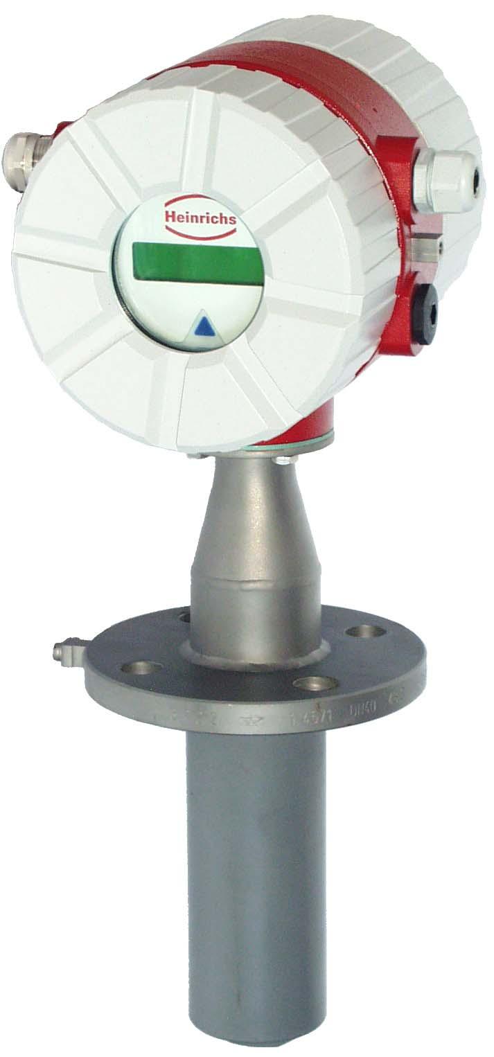
1 Magnetic-Inductive Flow Velocity Sensor PIT Device Description
2 Table of contents 1 IDENTIFICATION Manufacturer/supplier Product type Product name Issue date Version no APPLICATIONS OPERATIONAL MODE AND SYSTEM DESIGN Operational mode System design Transmitter mounted on the sensor Transmitter installed separately PIT PIT PIT PIT CHARACTERISTIC VALUES Measuring accuracy Conductivity of the medium Influence of ambient temperature Influence of medium temperature CONDITIONS OF USE Installation conditions Depth of immersion of the PIT-*** in the pipe Dismounting/reinstalling the device under process pressure Grounding Use in hazardous areas Ambient conditions Ambient temperature ranges Storage temperature Climatic category Degree of protection Shock resistance/vibration resistance Medium temperature and pressure Transmitter is mounted on the sensor Transmitter is mounted separately DIMENSIONS/WEIGHT PIT-5** dimension drawing for separate transmitter PIT-5** dimension drawing with mounted transmitter in SG1 housing AUXILIARY POWER/ELECTRICAL CONNECTION CE MARK STANDARDS AND DIRECTIVES, CERTIFICATES AND APPROVALS OPTIONS Dismounting/reinstalling the device under process pressure PIT with IP 68 degree of protection Wiring diagram for IP 68 hazardous area version Wiring diagram for IP 68 standard version EC TYPE EXAMINATION CERTIFICATE SALES REPRESENTATIVES NOTES...12 Page 2 of 12
3 1 Identification 1.1 Manufacturer/supplier Heinrichs Messtechnik GmbH Robert-Perthel-Str. 9 D Köln Phone: +49 (221) Fax: +49 (221) Internet: mailto:info@heinrichs-mt.com 1.2 Product type Magnetic-inductive flow sensor based upon Faraday's law of induction 1.3 Product name PIT-520, PIT-580, PIT-571 and PIT Issue date 23/02/ Version no. 3.0 File: PIT_GB_ 03_eng.doc 3 Operational mode and system design 3.1 Operational mode It was back in 1832 that Faraday suggested utilizing the principle of electrodynamic induction for measuring flow velocities. His experiments in the Thames, though unsuccessful due to superimposed polarization effects, are nonetheless regarded as the first ones in the field of magnetic-inductive flow measurement. According to Faraday s law of electromagnetic induction, an electrical field E is produced in a conductive liquid moving through a magnetic field B at a velocity v in accordance with the vector product E = [v x B]. A liquid at flow velocity v and a flow rate Q flows through a meter tube (4), producing a measuring-circuit voltage Um at the two electrodes (E1 and E2) at right angles to the direction of flow and the magnetic field B generated by the field coils (3). The size of this measuring-circuit voltage is proportional to the mean flow velocity and thus the volume flow rate. 2 Applications The magnetic-inductive PIT flow velocity sensor is used to measure or monitor the volume flow of liquids with and without solids concentration, slurries, pastes and other electrically conductive media while minimizing pressure drops. The conductivity of the medium must be at least 20 µs/cm. Pressure, temperature, density and viscosity do not affect the volume measurements. Smaller portions of solid particles and small gas pockets are also measured as part of the volume flow. A larger number of solid particles or gas pockets will lead to failures. Special electrodes are available for media that tend to form greasy films or crusts. 3.2 System design The magnetic-inductive PIT-*** flow measurement system consists of a sensor, which picks up an induced measuring signal from the medium flowing through the pipe, and a transmitter, which transforms this signal in standardized output signals (4-20 ma or pulses). The PIT-*** sensor can be operated with all transmitters for magnetic-inductive flowmeters manufactured by Heinrichs Messtechnik. The sensor is installed in the pipe while the transmitter is mounted directly on the sensor or separately on the outside, depending on the equipment design. Page 3 of 12
4 3.2.1 Transmitter mounted on the sensor This type of construction ensures easy and trouble-free installation. 206 SG1 transmitter housing PIT-520 Socket of sensor housing and flange are made of stainless steel PIT-580 Socket of sensor housing and flange are made of Hastelloy. Fitting Flow direction (arrow) Flange Ground connection Socket weld fitting Lining Electrodes 15 % depth of immersion of pipe dia.-ø PIT-571 Socket of sensor housing and flange are made of stainless steel. The wetted parts of the housing are PFA-coated PIT-573 Socket of sensor housing and flange are made of stainless steel. The wetted parts of the housing are PFDF-coated. 4 Characteristic values 4.1 Measuring accuracy ± 1.5 % of measured value plus ± 0.5 % of URV 4.2 Conductivity of the medium 20 µs/cm 4.3 Influence of ambient temperature See transmitter 4.4 Influence of medium temperature None Transmitter installed separately Heinrichs Messtechnik recommends this type of installation when there is little space or the medium temperatures are high. The sensor and the transmitter are connected by a field coil and an electrode cable. The electrode cable must be shielded and protected against disturbing interferences. Terminal box with partial certificate for connecting approved transmitters 75 5 Conditions of use 5.1 Installation conditions Disturbing elements (e.g. shut-off and control devices) are to be arranged downstream from the sensor. If this is not possible, flow straighteners must be installed so that no vortexes can reach into the pipe section of the sensor. The mounting location in the pipe system should be selected so that the sensor is continually filled with the medium. This requirement can be met by using drains and non-return valves. Fitting Flow direction (arrow) Flange Ground connection Socket weld fitting 15 % depth of immersion of pipe dia.-ø Lining Electrodes Page 4 of 12
5 In order to stay within the indicated error limits, the installation must be performed according to EN "Measurement of Fluid Flow in Closed Conduits Methods of Evaluating the Performance of Magnetic-Inductive Flowmeters." Based on this standard, the minimum straight run of pipe ahead of the inlet must be 10 pipe diameters (> 10 x DN) and 5 pipe diameters following the outlet (> 5 x DN) [DN = nominal diameter of pipe]. In order to prevent serious measuring errors when the pipe is partially filled or when there are gas pockets or sediment deposits, the mounting position described above should be chosen. The limit values for the product and ambient temperature must be met at the mounting location. Corrosive atmospheres must be avoided. Please also take into account the space requirement for a possible removal of the device Depth of immersion of the PIT-*** in the pipe In order to suppress the influence of the flow profile as much as possible, the depth of immersion of the measuring head in the pipe must be 15 % of the inside diameter of the pipe. The socket weld fitting must not cover the top of the measuring head and must be shortened if necessary Dismounting/reinstalling the device under process pressure For easily dismounting and reinstalling the device under process pressure, a version with a special mechanism is available. When using this mechanism, the measuring head must not be damaged by closing the valve. For details, see the Additional Operating Instructions for Dismounting and Reinstalling the Device under Process Pressure (see also Section 14 "Options") Grounding For safety reasons and to ensure faultless operation of the magnetic-inductive flowmeter, grounding the flow sensor is important. In accordance with VDE 0100, Part 540, the ground connections must be at protective conductor potential. For the hazardous area version, they must be equipotentially bonded. For metrological reasons, the potential should be identical to the potential of the medium. When using insulated and lined pipes or plastic pipes, the metrological grounding of the medium for PIT-520/580 is carried out via the wetted part of the measuring head. All wetted parts of PIT-571 are coated with PFA (PIT-573 with PVDF). It is therefore not possible to ground the medium via the housing parts. In this case, a special version of PIT-571/PIT-573 equipped with a grounding electrode is necessary. 5.2 Use in hazardous areas The PIT-520 and PIT-571 flowmeters can also be used in Zone 1 hazardous areas. Only devices with a corresponding mark on their type plate may be operated in these areas. The special conditions with regard to the relationship between the thermal data and the medium temperature, ambient temperature and the temperature class in accordance with the EC Type Examination Certificate BVS 03 ATEX 150 X must be observed. When installing and operating the device in hazardous areas, the applicable national rules must be followed. 5.3 Ambient conditions Ambient temperature ranges -40 C to +60 C For the hazardous area version, take note of the maximum ambient temperatures depending on the temperature class as specified in the Type Examination Certificate Storage temperature The storage temperatures are identical to the ambient temperature ranges Climatic category In accordance with IEC Not weather-protected Class D locations exposed directly to open-air climate Degree of protection Standard version: IP 65 Special version: IP 68 Weather-protected and/or unheated locations, class C Shock resistance/vibration resistance The meter should be protected from extreme shocks and vibrations, which could cause damage. 5.4 Medium temperature and pressure Transmitter is mounted on the sensor Version Medium temperature Pressure PIT-520/580 standard -20 C to 80 C 16 bar PIT-571 standard -20 C to 80 C 40 bar PIT-573 standard -20 C to 80 C 40 bar Transmitter is mounted separately Version Medium temperature Pressure PIT-520/580 standard -40 C to100 C 16 bar PIT-571 standard -40 C to 140 C 40 bar PIT-573 standard -20 C to 80 C 40 bar Page 5 of 12
6 6 Dimensions/weight 6.1 PIT-5** dimension drawing for separate transmitter 80 Length of sensor T 5 Length of weld fitting L Sensor Ød1 Weight: 3.6 kg Ø70 Version DN Sensor Length of Sensor- Length of weld lining sensor T Ø fitting L PIT PFA PIT PVDF PIT ,3 145 PIT ,3 170 PIT ,3 170 Page 6 of 12
7 6.2 PIT-5** dimension drawing with mounted transmitter in SG1 housing 150 Length of sensor T 5 Socket weld fitting L Weight: 7.6 kg Ø70 Sensor Ød1 Version DN Sensor Length of Sensor- Length of weld lining sensor T Ø fitting L PIT PFA PIT PVDF PIT ,3 145 PIT ,3 170 PIT ,3 170 Page 7 of 12
8 7 Auxiliary power/electrical connection See type plate or Operating Instructions of the corresponding transmitter 8 CE Mark The measuring system complies with the legal requirements of the following EU Directives: 94/9/EC (Equipment and Protective Systems for Use in Potentially Explosive Atmospheres), Directive 89/336/EEC (EMC Directive) and Directive 97/23/EC (Pressure Equipment Directive). Heinrichs Messtechnik confirms compliance with the directives by attaching the CE mark to the device. 10 Options 10.1 Dismounting/reinstalling the device under process pressure In some cases it might be necessary to dismount and reinstall the PIT for cleaning when the pipe is under process pressure. A special mechanism can be used for this purpose. When using this mechanism, it is important to ensure that the measuring head will not be damaged by closing the valve. For a detailed description of this process, see the Additional Operating Instructions for Dismounting/Reinstalling the Device under Process Pressure (Section 5.1.2). 9 Standards and directives, certificates and approvals Certified to DIN-EN 9001 Production in accordance with AD guidelines and HPO approval (TRB200/TRD201) TÜV approval for welding requirements in accordance with DIN-EN Directive 94/9/EC EN 50014:1997+A1-A2 EN 50019:2000 EN 50020:1994 Directive 89/336/EEC EN :1999 EN EN 55011:1998+A1:1999 Direcitve 97/23/EC AD guidelines (Equipment and Protective Systems for Use in Potentially Explosive Atmospheres) General requirements Increased safety "e" Intrinsic safety i (EMC Directive) Immunity industrial environment Emitted interference residential environment Group 1, Class B (Pressure Equipment Directive) NAMUR recommendation NE 21 EN Degrees of protection through housing (IP code) EN Safety requirements for electrical measuring, control and laboratory devices Page 8 of 12
9 10.2 PIT with IP 68 degree of protection A special version of PIT is available with the IP 68 degree of protection. This version is equipped with a special terminal box, special cable glands and a special cable. The length of the cable must be specified when placing the order. The terminal box does not need to be opened during the installation. If this should be necessary, the cover must be remounted carefully. This is the only way to ensure the IP 68 degree of protection. The maximum depth of immersion is 5 m. Due to the separate wiring arrangement of intrinsically safe and not intrinsically safe circuits for hazardous area applications, two cables are available for this version Wiring diagram for IP 68 hazardous area version Wiring diagram for IP 68 standard version Page 9 of 12
10 11 EC Type Examination Certificate Page 10 of 12
11 Page 11 of 12
12 12 Sales representatives See Internet: 13 Notes Page 12 of 12
Magnetic-Inductive Flow Velocity Sensor PIT. Installation and Operating Instructions
 Magnetic-Inductive Flow Velocity Sensor PIT Installation and Operating Instructions Table of contents 1 IDENTIFICATION... 3 1.1 Manufacturer/supplier... 3 1.2 Product type... 3 1.3 Product name... 3 1.4
PIT UMF2 (B) Magnetic-Inductive Flow Velocity Sensor. Operating Manual. Page 1 of 14
 Magnetic-Inductive Flow Velocity Sensor. Operating Manual. Page 1 of 14") Magnetic-Inductive Flow Velocity Sensor PIT UMF2 (B) Operating Manual Page 1 of 14 Heinrichs Messtechnik GmbH Operating Manual PIT-UMF2 (B) Contents 1 IDENTIFICATION... 3 1.1 Manufacturer/supplier... 3
Magnetic-Inductive Flow Velocity Sensor PIT UMF2 (B) Operating Manual Page 1 of 14 Heinrichs Messtechnik GmbH Operating Manual PIT-UMF2 (B) Contents 1 IDENTIFICATION... 3 1.1 Manufacturer/supplier... 3
Pressure sensors. Ex ia I / IIC T6 acc. to ATEX. Features. Description. Measuring ranges. Applications
 Force Pressure Temperature Switch Pressure sensors Ex ia I / IIC T6 acc. to ATEX with internal diaphragm with front flush diaphragm Accuracy: 0,25% and 0,5 % Standard output: 4...20 ma; 2-wire system Description
OPTIBAR P 1010/2010 C Supplementary instructions
 OPTIBAR P 1010/2010 C Supplementary instructions Pressure transmitter Equipment category II 1G / Ga, II 1D / Da in protection type intrinsic safety Exi KROHNE CONTENTS OPTIBAR P 1010/2010 C 1 Safety instructions
OPTIBAR DP 7060 Supplementary Instructions
 OPTIBAR DP 7060 Supplementary Instructions Differential pressure transmitter Category ATEX II 1/2G, 2G Ex db ia IIC T6...T1 Ga/Gb, Gb IECEx Ex db ia IIC T6...T1 Ga/Gb, Gb Housing Aluminium: Single chamber,
Inductive slot sensor
 0102 Model Number Features 2 mm slot width Technical Data specifications Switching function Normally closed (NC) Output type NAMUR Slot width 2 mm Depth of immersion (lateral) 5... 7 mm, typ. 6 mm Output
Ultrasonic Level Measurement nivopuls FDU 10 S
 Technical Information TI 275F/00/en Ultrasonic Level Measurement nivopuls FDU 10 S Level limit switch for liquids with separate electronics unit Non-contact from outside Suitable for use in explosion hazardous
Technical Data. Dimensions
 0102 Model Number Features Comfort series 50 mm non-flush Technical Data specifications Switching element function NAMUR, NC Rated operating distance s n 50 mm Installation non-flush Output polarity NAMUR
Additional Operating Instructions SITRANS F. Vortex flowmeters. SITRANS FX330 Ex-d.
 Additional Operating Instructions SITRANS F Vortex flowmeters Ex-d Edition 09/208 CONTENTS Safety instructions 3. General notes... 3.2 EU conformity... 3.3 Approval according to the IECEx scheme... 3.4
Technical Data. General specifications Switching element function Rated operating distance s n 4 mm
 0102 Model Number Features 4 mm non-flush Accessories BF 12 Mounting flange, 12 mm Technical Data specifications Switching element function NAMUR, NO Rated operating distance s n 4 mm Installation non-flush
Additional Operating Instructions SITRANS F. Vortex flowmeters. SITRANS FX330 Ex-nA.
 Additional Operating Instructions SITRANS F Vortex flowmeters Ex-nA Edition 08/207 CONTENTS Safety instructions 3. General notes... 3.2 EU conformity... 3.3 Approval according to the IECEx scheme... 3.4
VERSAFLOW VORTEX Supplementary instructions
 VERSAFLOW VORTEX Supplementary instructions Vortex flowmeter Equipment category II 2G CONTENTS VERSAFLOW VORTEX 1 Safety instructions 3 1.1 General notes... 3 1.2 EC conformity... 3 1.3 Approval according
MagMaster MFE flowmeters feature an innovative multifrequency
 INDUSTRIAL INSTRUMENTS AND CONTROLS SPECIALIST Kent-Taylor MagMaster MFE Series Flowmeters Electromagnetic Sensors Features Include Unrivalled flow performance- ±0.2% accuracy. Pulsed DC Technology Incorporates
Flow Measurement SITRANS F C
 Overview The flow measuring principle is based on the Coriolis Effect. The FCS sensor s measuring tubes are energized by an electromechanical driver circuit which oscillates them at their resonance frequency.
ORIGA-SENSOFLEX Displacement Measuring System for Cylinder Series OSP-P
 ORIGA-SENSOFLEX Displacement Measuring System for Cylinder Series OSP-P Contents Description Data Sheet No. Page Overview P-1.50.001E 117-118 Technical Data SFI-plus P-1.50.002E-1, 2 119-120 Dimensions
enproteko.com Specifications Ratings Item voltage to 24 VAC 5/6 Hz 24 VAC 5/6 Hz or 24 VDC Allowable voltage Characteristics 85% to 11% of power suppl
 enproteko.com Temperature Monitoring Relay K8AB-TH Compact and Slim Relay Ideal for Temperature Alarms and Monitoring Excessive increases can be prevented and abnormal s can be monitored. Temperature monitoring
Technical Data. Dimensions
 0102 Model Number Features 15 mm non-flush Technical Data specifications Switching element function NAMUR, NC Rated operating distance s n 15 mm Installation non-flush Assured operating distance s a 0...
Installation and Operating Instruction
 Installation and Operating Instruction Automatic Fire Detectors Series 900 Ex (i) 9893 0.00 GB Technical changes reserved! 0 Installation and Operating Instruction Automatic Fire Detectors Series 900 Ex
Intrinsically Safe Pressure Transmitters for installation in hazardous locations Models IS-20-S, IS-21-S, IS-20-F, IS-21-F WIKA Datasheet IS-20
 Electronic Pressure Measurement Intrinsically Safe Pressure Transmitters for installation in hazardous locations Models IS-20-S, IS-21-S, IS-20-F, IS-21-F WIKA Datasheet IS-20 Applications Chemical, Petrochemical
Temperature Sensor TRG Original Installation Instructions English
 Temperature Sensor TRG 5-6.. EN English Original Installation Instructions 818597-05 1 Contents Important notes Page Usage for the intended purpose...4 Function...4 Safety note...4 Directives and standards
Hygro and Hygrothermal Transducers (Capacitive) for Air Conditioning Applications
 for Air Conditioning Applications") Data Sheet 907020 Page 1/9 Hygro and Hygrothermal Transducers (Capacitive) for Air Conditioning Applications For measuring relative humidity and temperature For versatile climatic applications and ventilation
Data Sheet 907020 Page 1/9 Hygro and Hygrothermal Transducers (Capacitive) for Air Conditioning Applications For measuring relative humidity and temperature For versatile climatic applications and ventilation
ProcessMaster, HygienicMaster FEX300, FEX500
 SM/FEX300/FEX500/ATEX/IECEX-EN ProcessMaster, HygienicMaster FEX300, FEX500 ATEX / IECEx Zone 1, 2, 21, 22 Safety instructions for electrical apparatus in potentially explosive areas, in accordance with
Supplementary Installation and Operating Instructions. Category II2G
 Supplementary Installation and Operating Instructions Flap-type Flow Meter Category II2G 2 Contents 1. General safety directions...3 2. Main safety-relevant characteristics...4 2.1. Category / Zone...4
for relative humidity and temperature
 1 861 1861P01 Duct sensor for relative humidity and temperature QFM65 Operating voltage AC 24 V Signal output DC 0...10 V for relative humidity and temperature Measurement accuracy ±3 % r. h. within the
DSF xx10.xx xhv Ex-Atex Hall Effect Single Channel Speed Sensor
 Product ID Type # Product # Drawing # DSF 1210.00 SHV Ex-atex (2m) 374Z-05066 110428F1 DSF 1210.00 SHV Ex-atex (5m) 374Z-05176 110428F1 DSF 1210.00 SHV Ex-atex (10m) 374Z-05590 110428F1 DSF 1410.00 SHV
Conductivity Electrode LRG Original Installation Instructions English
 Conductivity Electrode LRG 16-4 EN English Original Installation Instructions 818854-02 1 Contents Important notes Page Usage for the intended purpose...4 Function...4 Safety note...5 Directives and standards
Technical Data. General specifications Switching element function Rated operating distance s n 5 mm
 0102 Model Number Features 5 mm non-flush Usable up to SIL2 acc. to IEC 61508 Technical Data specifications Switching element function NAMUR, NC Rated operating distance s n 5 mm Installation non-flush
Operating manual GTL 369 GTL 369M GTL 389 GTL 389M. Temperature probe. Please keep the manual for future use.
 Operating manual Temperature probe GTL 369 GTL 369M GTL 389 GTL 389M Please keep the manual for future use. L02.0.3X.6C-01 GREISINGER electronic GmbH Hans-Sachs-Str. 26 93128 Regenstauf Germany Fon +49(0)9402-9383-0
Additional Operating Instructions SITRANS F. Vortex flowmeters. SITRANS FX330 Ex-i.
 Additional Operating Instructions SITRANS F Vortex flowmeters Ex-i Edition 09/2018 CONTENTS 1 Safety instructions 3 1.1 General notes... 3 1.2 EU conformity... 3 1.3 Approval according to the IECEx scheme...
Flow switch. Operating Manual. English manual page Page 1 of 15 Fax:
 Operating Manual www.jlso-tec-trade.de Flow switch English manual page 1-15 Page 1 of 15 Flow switch Table of Contents Page 1 Device Description and Intended Use... 19 1.1 Flow switch version VH...X...
OPTISENS TUR 2000 Technical Datasheet
 OPTISENS TUR 2000 Technical Datasheet Sensor for turbidity measurement in water and wastewater Rugged design for harsh applications Integrated transmitter with direct 4...20 ma output Near infrared light
Instruction Manual. Alarm Unit For Low Gas Level # Read manual before use! Observe all safety information! Keep manual for future use!
 Mess-, Regel- und Überwachungsgeräte für Haustechnik, Industrie und Umweltschutz Lindenstraße 20 74363 Güglingen Telefon +49 7135-102-0 Service +49 7135-102-211 Telefax +49 7135-102-147 info@afriso.de
PEPPERL+FUCHS GmbH
 Comfort series 1.5 mm embeddable M8x1 4 25 16 13 LED Switching element function NAMUR NC Rated operating distance s n 1,5 mm Installation embeddable Assured operating distance s a 0... 1,215 mm Reduction
OEM Sensors for HVAC manufacturers Heat recovery Chiller
 OEM Sensors for HVAC manufacturers Heat recovery Chiller 2 Heat recovery / Chiller Typical magnetic-inductive flow sensor application Product features For determining the energy balance Measurement signal
UW Purchase Specification Section Steam Condensate or Hot Water Meter Page 1 of 9
 Page 1 of 9 PART 1 GENERAL 1.02 DESCRIPTION A. Purpose 1. This section covers steam condensate meters, steam condensate sub-meters and hot water sub-meters for use in the Owner's steam systems. 1.03 QUALIFICATIONS
Product ID. General. TE CONNECTIVITY SENSORS /// EXxxHyy Ex-Atex & NA 09/2017 Page 1
 s for use in explosive atmospheres Europe ATEX II 2 G and North America ClI, Div 1 & 2 and Cl II, Div 1 & 2 and Cl III and North America Cl I, Zone 1 Product ID Type # Product # Drawing # EX34H 385Z-05637
Hygro and Hygrothermo Transducers (capacitive) for climatic applications
 for climatic applications") Data sheet 907020 Page 1/7 Hygro and Hygrothermo Transducers (capacitive) for climatic applications To measure relative humidity and temperature For versatile climatic applications and ventilation For
Data sheet 907020 Page 1/7 Hygro and Hygrothermo Transducers (capacitive) for climatic applications To measure relative humidity and temperature For versatile climatic applications and ventilation For
itemp RTD TMT 187 itemp TC TMT 188 Temperature head transmitter
 BA 104R/24/ae/10.03 itemp RTD TMT 187 itemp TC TMT 188 Temperature head transmitter Operating instructions RTD TC TMT 187 TMT 188 Temperature head transmitter Safety message # Warning! Instructions and
Technical Data. General specifications. Rated operating distance s n 5 mm
 0102 Model Number Features 5 mm non-flush Usable up to SIL 2 acc. to IEC 61508 Technical Data specifications Switching function Normally closed (NC) Output type NAMUR Rated operating distance s n 5 mm
Technical Data. Dimensions
 0102 Model Number Features 5 mm flush Usable up to SIL2 acc. to IEC 61508 Accessories EXG-18 Quick mounting bracket with dead stop BF 18 Mounting flange, 18 mm Technical Data specifications Switching element
PRODUCT CONFORMITY CERTIFICATE
 PRODUCT CONFORMITY CERTIFICATE This is to certify that the SITRANS F M MAG 5100W Electromagnetic Flowmeter with MAG 5000, MAG 6000 or MAG 6000 Industry Transmitter DE-76181 Karlsruhe Germany manufactured
Technical Data. Dimensions
 0102 Model Number Features 8 mm non-flush Stainless steel housing Usable up to SIL2 acc. to IEC 61508 Technical Data specifications Switching element function NAMUR, NC Rated operating distance s n 8 mm
CoriolisMaster FCM2000
 CI/FCM2000-EN CoriolisMaster FCM2000 EN English Commissioning Instruction Mass Flowmeter CoriolisMaster FCM2000 P R O F I PROCESS FIELD BUS B U S Neu Contents Mass Flowmeter CoriolisMaster FCM2000 Commissioning
Immersion heaters for ATEX/IECEx hazardous areas or in non-atex version
 for ATEX/IECEx hazardous areas or in non-atex version * Non contractual picture Warning It is imperative to read these instructions carefully before installing or maintaining the equipment. MI100EN 09/2017
Hygro/hygrothermal transducers (hygrometric)
") Data Sheet 90.7031 Page 1/7 Hygro/hygrothermal transducers (hygrometric) for measuring relative humidity and temperature for mounting indoors, outdoors, and in air ducts with resistance, current or voltage
Data Sheet 90.7031 Page 1/7 Hygro/hygrothermal transducers (hygrometric) for measuring relative humidity and temperature for mounting indoors, outdoors, and in air ducts with resistance, current or voltage
Circulation heaters for ATEX/IECEx hazardous areas or in non-atex version
 for ATEX/IECEx hazardous areas or in non-atex version * Non contractual picture Warning It is imperative to read these instructions carefully before installing or maintaining the equipment. MI500EN 09/2017
Duct heaters for ATEX/IECEx hazardous areas or in non-atex version
 for ATEX/IECEx hazardous areas or in non-atex version * Non contractual picture Warning It is imperative to read these instructions carefully before installing or maintaining the equipment. MI200EN 09/2017
DSF xx15.xx xhv Ex-Atex Ex-Atex Certified Two wire Hall Effect Speed Sensor
 DSF xx15.xx xhv Ex-Atex Product ID Type # Product # Drawing # DSF 1215.01 SHV Ex-atex (5m) 304Z-05197 113216 DSF 1415.01 AHV Ex-atex S148 304Z-05256 113351 DSF 1615.01 SHV Ex-atex (5m) 304Z-05196 113214
Technical Data. General specifications Switching element function Rated operating distance s n 5 mm
 0102 Model Number Features 5 mm flush Usable up to SIL 3 acc. to IEC 61508 Application Danger! In safety-related applications the sensor must be operated with a qualified fail safe interface from Pepperl+Fuchs,
SECTION INDUCTIVE CONDUCTIVITY ANALYZERS
 SECTION 40 75 16 INDUCTIVE CONDUCTIVITY ANALYZERS PART 1 General 1.01 SUMMARY A. Requirements for a digital inductive conductivity sensor for standard, hazardous and hightemperature applications. The sensor
Operating Manual MS220KA and MSR220KA
 Temperature Relays and MINIKA, Mains Monitoring, Digital Panel meters MINIPAN, Switching Relays and Controls Operating Manual MS220KA and MSR220KA ZIEHL industrie elektronik GmbH + Co KG Daimlerstraße
Rotameter series 250 metal tube variable area flowmeter
 Technical data Sheet Flow meter Rotameter series 250 metal tube variable area flowmeter MODELES 250 Stainless Steel indicator 250 PTFE 250 indicator + Alarm 250 electronic transmitter 4-20mA 250 electronic
BSK-RPR Fire Damper. Additional operating instructions according to
 Additional operating instructions according to BSK-RPR Fire Damper Contents GENERAL CONDITIONS... 1 DESCRIPTION... 3... 4 EC Certificate of Conformity 0761 CPD 0245 Declaration of Performance 09-22-DoP-BSK-RPR-2013-07-01
SPECIFICATIONS - DETAILED PROVISIONS Section Magnetic Flowmeters C O N T E N T S
 Revised 04/13/16 SPECIFICATIONS - DETAILED PROVISIONS Section 17210 - Magnetic Flowmeters C O N T E N T S PART 1 - GENERAL... 1 1.01 GENERAL REQUIREMENTS... 1 1.02 PROJECT SPECIFIC REQUIREMENTS... 1 1.03
Gas cylinder scale Model GCS-1
 Electronic pressure measurement Gas cylinder scale Model GCS-1 WIKA data sheet PE 87.19 Applications Level measurement of liquid gases in gas cabinets and gas distribution systems Level measurement in
SOUND-INSULATED FAN. Iso-K OPERATION MANUAL. Iso-K_v.1(2)-EN.indd :20:59
-EN.indd :20:59") SOUND-INSULATED FAN OPERATION MANUAL _v.1(2)-en.indd 1 10.08.2015 15:20:59 CONTENT Introduction 3 General 3 Safety rules 3 Transport and storage requirements 3 Manufacturer's warranty 3 Fan design 4 Delivery
SOUND-INSULATED FAN OPERATION MANUAL _v.1(2)-en.indd 1 10.08.2015 15:20:59 CONTENT Introduction 3 General 3 Safety rules 3 Transport and storage requirements 3 Manufacturer's warranty 3 Fan design 4 Delivery
POINTEK CLS 100 OINTEK CLS 100 CAPACITANCE LIQUIDS/SOLIDS. Instruction Manual March 2001
 POINTEK CLS 100 CAPACITANCE LIQUIDS/SOLIDS Instruction Manual March 2001 OINTEK CLS 100 Safety Guidelines Warning notices must be observed to ensure personal safety as well as that of others, and to protect
OPTIWAVE X500 Supplementary Instructions
 OPTIWAVE X500 Supplementary Instructions OPTIWAVE 3500 C OPTIWAVE 6500 C OPTIWAVE 7500 C Supplementary Instructions for ATEX applications KROHNE CONTENTS OPTIWAVE X500 1 General safety information 4 1.1
Rosemount 3100 Series Ultrasonic Level Transmitters
 Product Data Sheet Ultrasonic Level Transmitters Non-contacting measurement with no moving parts Integral LCD and push-buttons as standard for on-site programming Continuous measurement of level or distance-to-surface.
Rod probe 11961Z. Technical Information. Conductive level limit detection Partially insulated rod probe for use in conductive liquids
 Technical Information Rod probe 11961Z Conductive level limit detection Partially insulated rod probe for use in conductive liquids Application Conductive level limit detection in process or storage tanks
Vibracon LVL-A* Level limit switch for liquids, compact design
 Technical Information TI 364O/98/en/.07 8905 /07 0 Vibracon LVL-A* Level limit switch for liquids, compact design Application The Vibracon LVL-A* is a level limit switch for all kinds of fluids and is
Level Electrode NRG Original Installation Instructions English
 Level Electrode NRG 16-36 EN English Original Installation Instructions 819257-01 Contents Contents Page Important notes Usage for the intended purpose...4 Function...4 Safety note...4 Directives and standards
SITRANS F. Electromagnetic Flowmeters. SITRANS F M MAG 3100 sensor. Operating Instructions. Answers for industry.
 SITRANS F Electromagnetic Flowmeters Operating Instructions Edition 09/2012 Answers for industry. Introduction 1 Safety notes 2 SITRANS F Electromagnetic Flowmeters Operating Instructions Description
Snifter ATEX22 VERSION. User Manual. Distributor
 Snifter ATEX22 VERSION User Manual Distributor Version 1.4 09/09/2009 Table of Contents 1. INTRODUCTION... 3 1.1. Safety... 3 1.2. Product overview... 4 1.3. How does it work?... 4 2. INSTALLATION... 5
Level Measurement Continuous level measurement Ultrasonic transmitters
 Overview Configuration is a short-range integrated ultrasonic level transmitter. This intrinsically safe, 2 wire, 4 to 20 ma loop powered transmitter is ideal for liquids, slurries, and bulk materials
for relative humidity and temperature
 1 860 1860P01 Duct sensor for relative humidity and temperature QFM651 Operating voltage AC 24 V Signal output DC 010 V for relative humidity Signal output L&S Ni 1000 (passive) for temperature Measurement
PRODUCT CONFORMITY CERTIFICATE
 PRODUCT CONFORMITY CERTIFICATE This is to certify that the SITRANS F M MAGFLO MAG 5100W Electromagnetic Flowmeter with MAG 5000, MAG 6000 or MAG 6000 Industry Transmitter manufactured by: Siemens Flow
TR FLEXMAG 4050 C Electromagnetic flow meter for single use processes
 TR 2017-03-06 FLEXMAG 4050 C Electromagnetic flow meter for single use processes 1. Introduction 2. Measuring principle 3. The FLEXMAG 4050 versions 4. Target applications 5. Technical Data FLEXMAG 4050
Process Automation. Sensors and Systems: Level Sensors Level Detectors Overfill Prevention. Process Automation. Accuracy.
 Process Automation Process Automation Accuracy Level Sensors Level Detectors Overfill Prevention Flexible Sensors and Systems: www.fafnir.com Reliable LS 300 and LS 500 Protect Your Most Valuable Assets
Differential pressure gauge with electrical contact type Model: P650 series
 Differential pressure gauge with electrical contact type Model: P650 series Service intended The P650 series are designed to measure a differential pressure from 25 kpa to 2.0 MPa at static pressure up
TRG 5-53 TRG 5-54 TRG 5-55 TRG 5-57
 GESTRA GESTRA Steam Systems TRG 5-53 TRG 5-54 TRG 5-55 TRG 5-57 EN English Installation & Operating Instructions 810428-05 Temperature Sensor TRG 5-53, TRG 5-54, TRG 5-55, TRG 5-57 1 Contents Application
AM54. Armored Variable Area Flowmeter Series AM54331/32 Series AM54371/72/73/74 Series AM54431/32 Series AM54471/72/73/74
 AM54 Instruction Bulletin North American Installation Addendum Document Number PN25016 Armored Variable Area Flowmeter Series AM54331/32 Series AM54371/72/73/74 Series AM54431/32 Series AM54471/72/73/74
Figure 1 TWM1000 Electromagnetic Flow Converter. 1. Large, illuminated graphic display with intuitive operation 2. For AC and DC operation
 TWM 1000 Electromagnetic Flow Converter Technical Datasheet 34-VF-03-24 August 29th, 2008 Specification The more than economical solution The TWM1000 offers a broad range of performance with an outstanding
MEAS Subermsible Liquid Level Pressure Transducer SPECIFICATIONS. Features. Applications
 MEAS 5700 Subermsible Liquid Level Pressure Transducer Features Heavy Industrial CE Approval 10 V/m EMI Protection Reverse Polarity Protection on Input Short Circuit Protection on Output ±0.25% Accuracy
Inductive Conductivity Measurement. Simultaneous display of conductivity/ resistance/salinity and temperature; large measurement symbol.
 Process Analysis Systems Chem Energy Pharm Food Water Stratos Eco 2405 CondI Inductive Conductivity Measurement Simultaneous display of conductivity/ resistance/salinity and temperature; large measurement
SITRANS F M MAG 3100 P:
 Dedicated for the chemical industry SITRANS F M MAG 3100 P: The electromagnetic flowmeter solution with devoted features. Process Instrumentation usa.siemens.com/mag The best choice for the chemical industry
CII FCAC-150 Series Relay
 Introducing CII Series Relay 50 Amps, 1PST/NO (DM) CII Series Relay 50 Amps, 1PST/NO (DM) with 1PDT Auxiliary Contacts KEY FEATURES Non-latching relay Balanced force design Corrosion protected metal enclosure
7NG , 7NG
 SITRANS TK-- L 7NG3120-- 0, 7NG3122-- 0 Edition 01/2003... Transmitter for temperature (Pt100) O per at ing ins t r uc t... ions SITR AN S TK--L A 5E 00095604-- 02 1 SIMATICr, SIPARTr, SIPROMr, SIRECr,
QFM21... Siemens Building Technologies HVAC Products. Symaro Duct Sensors. for relative humidity and temperature
 1 864 1864P01 Symaro Duct Sensors for relative humidity and temperature QFM21... Use Type summary Operating voltage AC 24 V or DC 13.5...3 Signal output DC 0...10 V for relative humidity Signal output
Technical Data. General specifications Switching element function DC Dual NC Rated operating distance s n 3 mm
 0102 Model Number Features Direct mounting on standard actuators EC-Type Examination Certificate TÜV99 ATEX 1479X Accessories BT32 BT32XS BT32XAS BT33 BT34 V1-G-N4-5M-PUR Female cordset, M12, 4-pin, NAMUR,
Control Thermostat / Thermal Reset Limit Thermostat Combination of electromechanical TR and TW
 1 212 Double thermostat Control Thermostat / Thermal Reset Limit Thermostat Combination of electromechanical TR and TW RAZ-TW... 2-position control thermostat and thermal reset limit thermostat with singlepole
UV Flame Supervision System
 7 783 UV Flame Supervision System DETACTOGYR LFE50 Series 02 ISO 9001 The LFE50 is a self-checking UV flame supervision system designed for use with continuously operating burners or for burners running
Rosemount 3100 Series Ultrasonic Level Transmitters
 Product Data Sheet Ultrasonic Level Transmitters Non-contacting measurement with no moving parts Integral LCD and push-buttons as standard for on-site programming Continuous measurement of level or distance-to-surface.
PROFIBUS-PA Display RID 261 PROFIBUS-PA
 Technical Information TI 071R/09/en Mat.-Nr.: 510 01194 PROFIBUS-PA Display RID 261 PROFIBUS-PA Display of process values and set point alarms on PROFIBUS-PA systems R Applications Direct connection to
QAF63.2 QAF63.6. Frost sensors for use on the air side. Building Technologies HVAC Products
 1 821 1821P01 Frost sensors for use on the air side Active capillary tube sensor for measuring the lowest temperature within a range of 0 15 C Operating voltage AC 24 V Signal output DC 0...10 V Use On
Mobrey MSP900SH Level and MSP900FH Flow Ultrasonic Transmitters
 Product Data Sheet Non-contacting measurement with no moving parts Fast and simple to install and configure Continuous measurement of level, contents (volume), or open channel flow MCERTS certified version
Technical Data. General specifications Switching element function Rated operating distance s n 8 mm
 0102 Model Number Features 8 mm non-flush Usable up to SIL 3 acc. to IEC 61508 Application Danger! In safety-related applications the sensor must be operated with a qualified fail safe interface from Pepperl+Fuchs,
Duct Sensors. Siemens Building Technologies HVAC Products. Symaro. for relative humitidy (high accuracy) and temperature
 and temperature") 1 882 1882P01 Symaro Duct Sensors for relative humitidy (high accuracy) and temperature QFM31 Use Examples Operating voltage AC 24 V / DC 1353 Signal output DC 010 V / 4 20 ma for relative humidity and
1 882 1882P01 Symaro Duct Sensors for relative humitidy (high accuracy) and temperature QFM31 Use Examples Operating voltage AC 24 V / DC 1353 Signal output DC 010 V / 4 20 ma for relative humidity and
FDOOT241-A9-Ex Multisensor fire detector
 FDOOT241-A9-Ex Multisensor fire detector ASAtechnology TM For potentially explosive areas Sinteso Collective Signal processing with ASAtechnology Multiple protocol detector (collective/fdnet-ex) Event-controlled
AND INSTALLATION MANUAL
 Labkotec Oy Myllyhaantie 6 FI-33960 PIRKKALA FINLAND Tel. +358 29 006 260 Fax +358 29 006 1260 Internet: www.labkotec.fi 10.10.2013 SET/DM3AL Level sensor OPERATION AND INSTALLATION MANUAL 1(5) SYMBOLS
U5700 Submersible Liquid Level Pressure Transducer
 SPECIFICATIONS High Accuracy CE Compliant and Waterproof UL Certified Variety of Pressure Port Configurations Waterproof Optional Stainless Steel Snubber IP68 Rated Connection and Submersible Polyurethane
Installation instructions
 Immersion Heater ROTKAPPE Angular Immersion Heater ROTKAPPE Installation instructions E-MA 10/19 04.13/1 Please supplement the following information from the model plate For the immersion heater ROTKAPPE
SITRANS Pressure transmitter SITRANS LH300 (7MF1575..) Transmitter for hydrostatic level Compact Operating Instructions
 Transmitter for hydrostatic level Compact Operating Instructions") SITRANS Pressure transmitter Compact Operating Instructions Legal information Warning notice system This manual contains notices you have to observe in order to ensure your personal safety, as well as
SITRANS Pressure transmitter Compact Operating Instructions Legal information Warning notice system This manual contains notices you have to observe in order to ensure your personal safety, as well as
PROTECT SRB 200EXi-1A
 2 Installation up to zone 1/21 J S L1 0V X1 X3 S11 S12 S21 S22 Installation up to zone 2 A1 F1 F2 U B U EXi U i 0V S12 S22 X1 X3 K1 Logic K2 K1 K2 13 23 U EXi SRB 200EXi U B -1A U i K1 K2 PA PA A1 A2 13
ExDetector IRCO2. ExDetector IRHC. Operating and Installation Instructions. Gas Detection and Warning Systems
 IRCO2 IRHC Operating and Installation Instructions Gas Detection and Warning Systems Important Instructions Prerequisites for safe and reliable operation of the system: Appropriate transport and handling
Operating Instructions for Limit switch Model: NBK-R NBK-RM NBK-RT NBK-RA
 Operating Instructions for Limit switch Model: NBK-R NBK-RM NBK-RT NBK-RA 1. Contents 1. Contents... 2 2. Note... 3 3. Instrument Inspection... 3 4. Regulation Use... 3 4.1 Electrical limit switch... 4
Temperature Measurement Transmitters for field mounting
 Siemens AG 07 Overview Application The SITRANS TF can be used everywhere where temperatures need to be measured under particularly harsh conditions. For that reasons users from all industries have opted
Instruction Manual September 2010 SITRANS LVL200S
 Instruction Manual September 2010 SITRANS LVL200S Contents Contents 1 About this document 1.1 Function.................................. 4 1.2 Target group.............................. 4 1.3 Symbolism
M5200 Industrial Pressure Transducer
 SPECIFICATIONS Wide Temperature Range Compact Variety of Pressure Ports and Electrical Configurations Optional Stainless Steel Snubber CE Compliant and Weatherproof UL Certified Gage, Sealed, Compound
Translation of the assembly instructions with operating instructions and technical appendix
 BA Ex-SBU Switch box type SBU-x(1,2,3)x Translation of the assembly instructions with operating instructions and technical appendix In accordance with EU ATEX Directive 2014/32/EU In accordance with EU