Magnetic-Inductive Flow Velocity Sensor PIT. Installation and Operating Instructions
|
|
|
- Bertha Hutchinson
- 6 years ago
- Views:
Transcription


1 Magnetic-Inductive Flow Velocity Sensor PIT Installation and Operating Instructions
2 Table of contents 1 IDENTIFICATION Manufacturer/supplier Product type Product name Issue date Version no APPLICATIONS OPERATIONAL MODE AND SYSTEM DESIGN Operational mode System design Transmitter mounted on the sensor Transmitter installed separately PIT PIT PIT PIT CHARACTERISTIC VALUES Measuring accuracy Conductivity of the medium Influence of ambient temperature Influence of medium temperature CONDITIONS OF USE Installation conditions Depth of immersion of the PIT-*** in the pipe Dismounting/reinstalling the device under process pressure Grounding Use in hazardous areas Ambient conditions Ambient temperature ranges Storage temperature Climatic category Degree of protection Shock resistance/vibration resistance Medium temperature and pressure Transmitter is mounted on the sensor Transmitter is mounted separately DIMENSIONS/WEIGHT PIT-5** dimension drawing for separate transmitter PIT-5** dimension drawing with mounted transmitter in SG1 housing AUXILIARY POWER/ELECTRICAL CONNECTION CE MARK8 9 STANDARDS AND DIRECTIVES, CERTIFICATES AND APPROVALS SAFETY INFORMATION Intended use Installation, start-up and operating personnel PACKAGING, STORAGE AND TRANSPORT MAINTENANCE RETURNING DEVICES FOR REPAIR AND SERVICE OPTIONS Dismounting/reinstalling the device under process pressure PIT with IP 68 degree of protection Wiring diagram for IP 68 hazardous area version Wiring diagram for IP 68 standard version EC TYPE EXAMINATION CERTIFICATE DECONTAMINATION CERTIFICATE FOR DEVICE CLEANING Page 2 of 12
3 Introduction These Installation and Operating Instructions serve as a tool for the correct installation, operation and maintenance of the device. They are a supplement to the PIT Device Description. Read theses manuals carefully before the device is installed and put into use. They do not include special versions or applications. All devices were thoroughly checked for order compliance and operability before delivery. Upon receipt, please conduct a visual inspection of possible damage that may be identified as having occurred during shipment. If you discover any defect, please contact our head office in Cologne or the local sales office responsible for your area (see the telephone directory at the end of this manual or on our Web site). Apart from a description of the error, we will need the equipment type and serial number of the delivery. Heinrichs Messtechnik shall not furnish guarantee for any repair work done without prior notice. Unless otherwise agreed on, the rejected parts must be made available to us in case a claim is made. 1 Identification 1.1 Manufacturer/supplier Heinrichs Messtechnik GmbH Robert-Perthel-Str. 9 D Köln Phone: +49 (221) Fax: +49 (221) Internet: mailto:info@heinrichs.eu 1.2 Product type Magnetic-inductive flow sensor based upon Faraday's law of induction 1.3 Product name PIT-520, PIT-580, PIT-571 and PIT Issue date 01/02/ Version no. 6.0 File: PIT_BA_ 06_en.doc 2 Applications The magnetic-inductive PIT flow velocity sensor is used to measure or monitor the volume flow of liquids with and without solids concentration, slurries, pastes and other electrically conductive media while minimizing pressure drops. The conductivity of the medium must be at least 20 µs/cm. 3 Operational mode and system design 3.1 Operational mode It was back in 1832 that Faraday suggested utilizing the principle of electrodynamic induction for measuring flow velocities. His experiments in the Thames, though unsuccessful due to superimposed polarization effects, are nonetheless regarded as the first ones in the field of magnetic-inductive flow measurement. According to Faraday s law of electromagnetic induction, an electrical field E is produced in a conductive liquid moving through a magnetic field B at a velocity v in accordance with the vector product E = [v x B]. A liquid at flow velocity v and a flow rate Q flows through a meter tube (4), producing a measuring-circuit voltage Um at the two electrodes (E1 and E2) at right angles to the direction of flow and the magnetic field B generated by the field coils (3). The size of this measuring-circuit voltage is proportional to the mean flow velocity and thus the volume flow rate. 3.2 System design The magnetic-inductive PIT-*** flow measurement system consists of a sensor, which picks up an induced measuring signal from the medium flowing through the pipe, and a transmitter, which transforms this signal in standardized output signals (4-20 ma or pulses). The PIT-*** sensor can be operated with all transmitters for magnetic-inductive flowmeters manufactured by Heinrichs Messtechnik. The sensor is installed in the pipe while the transmitter is mounted directly on the sensor or separately on the outside, depending on the equipment design. Pressure, temperature, density and viscosity do not affect the volume measurements. Smaller portions of solid particles and small gas pockets are also measured as part of the volume flow. A larger number of solid particles or gas pockets will lead to failures. Special electrodes are available for media that tend to form greasy films or crusts. Page 3 of 12
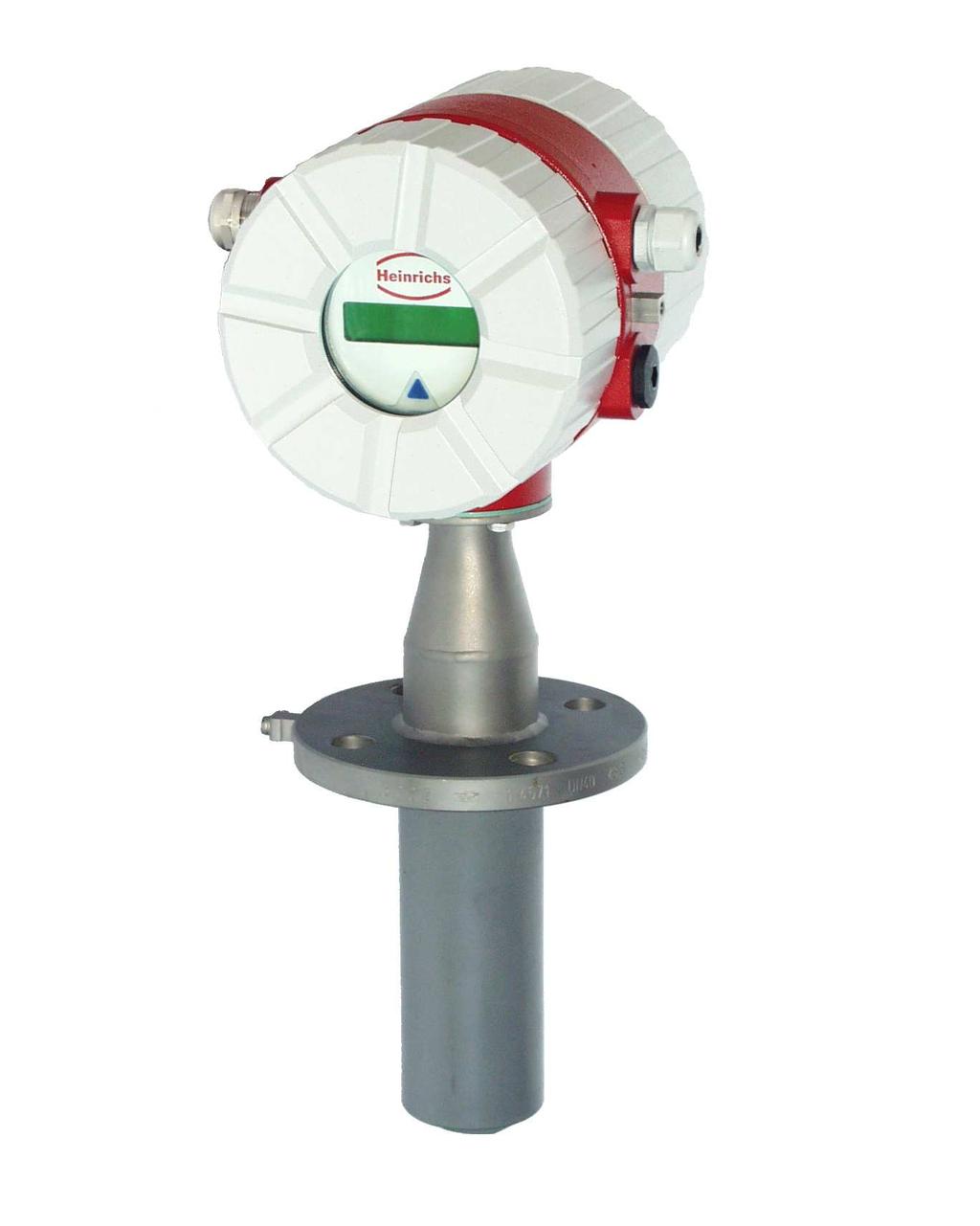
4 3.2.1 Transmitter mounted on the sensor This type of construction ensures easy and trouble-free installation. 206 SG1 transmitter housing PIT-520 Socket of sensor housing and flange are made of stainless steel PIT-580 Socket of sensor housing and flange are made of Hastelloy. Fitting Flow direction (arrow) Flange Ground connection Socket weld fitting Lining Electrodes 15 % depth of immersion of pipe dia.-ø PIT-571 Socket of sensor housing and flange are made of stainless steel. The wetted parts of the housing are PFA-coated PIT-573 Socket of sensor housing and flange are made of stainless steel. The wetted parts of the housing are PFDF-coated. 4 Characteristic values 4.1 Measuring accuracy ± 1.5 % of measured value plus ± 0.5 % of URV 4.2 Conductivity of the medium 20 µs/cm 4.3 Influence of ambient temperature See transmitter 4.4 Influence of medium temperature None Transmitter installed separately Heinrichs Messtechnik recommends this type of installation when there is little space or the medium temperatures are high. The sensor and the transmitter are connected by a field coil and an electrode cable. The electrode cable must be shielded and protected against disturbing interferences. Terminal box with partial certificate for connecting approved transmitters 75 5 Conditions of use 5.1 Installation conditions Disturbing elements (e.g. shut-off and control devices) are to be arranged downstream from the sensor. If this is not possible, flow straighteners must be installed so that no vortexes can reach into the pipe section of the sensor. The mounting location in the pipe system should be selected so that the sensor is continually filled with the medium. This requirement can be met by using drains and non-return valves. Fitting Flow direction (arrow) Flange Ground connection Socket weld fitting 15 % depth of immersion of pipe dia.-ø Lining Electrodes Page 4 of 12
5 In order to stay within the indicated error limits, the installation must be performed according to EN "Measurement of Fluid Flow in Closed Conduits Methods of Evaluating the Performance of Magnetic-Inductive Flowmeters." Based on this standard, the minimum straight run of pipe ahead of the inlet must be 10 pipe diameters (> 10 x DN) and 5 pipe diameters following the outlet (> 5 x DN) [DN = nominal diameter of pipe]. In order to prevent serious measuring errors when the pipe is partially filled or when there are gas pockets or sediment deposits, the mounting position described above should be chosen. The limit values for the product and ambient temperature must be met at the mounting location. Corrosive atmospheres must be avoided. Please also take into account the space requirement for a possible removal of the device Depth of immersion of the PIT-*** in the pipe In order to suppress the influence of the flow profile as much as possible, the depth of immersion of the measuring head in the pipe must be 15 % of the inside diameter of the pipe. The socket weld fitting must not cover the top of the measuring head and must be shortened if necessary Dismounting/reinstalling the device under process pressure For easily dismounting and reinstalling the device under process pressure, a version with a special mechanism is available. When using this mechanism, the measuring head must not be damaged by closing the valve. For details, see the Additional Operating Instructions for Dismounting and Reinstalling the Device under Process Pressure (see also Section 14 "Options") Grounding For safety reasons and to ensure faultless operation of the magnetic-inductive flowmeter, grounding the flow sensor is important. In accordance with VDE 0100, Part 540, the ground connections must be at protective conductor potential. For the hazardous area version, they must be equipotentially bonded. For metrological reasons, the potential should be identical to the potential of the medium. When using insulated and lined pipes or plastic pipes, the metrological grounding of the medium for PIT-520/580 is carried out via the wetted part of the measuring head. All wetted parts of PIT-571 are coated with PFA (PIT-573 with PVDF). It is therefore not possible to ground the medium via the housing parts. In this case, a special version of PIT-571/PIT-573 equipped with a grounding electrode is necessary. 5.2 Use in hazardous areas The PIT-520 and PIT-571 flowmeters can also be used in Zone 1 hazardous areas. Only devices with a corresponding mark on their type plate may be operated in these areas. The special conditions with regard to the relationship between the thermal data and the medium temperature, ambient temperature and the temperature class in accordance with the EC Type Examination Certificate BVS 03 ATEX 150 X must be observed. When installing and operating the device in hazardous areas, the applicable national rules must be followed. 5.3 Ambient conditions Ambient temperature ranges -40 C to +60 C For the hazardous area version, take note of the maximum ambient temperatures depending on the temperature class as specified in the Type Examination Certificate Storage temperature The storage temperatures are identical to the ambient temperature ranges Climatic category In accordance with IEC Not weather-protected Class D locations exposed directly to open-air climate Degree of protection Standard version: IP 65 Special version: IP 68 Weather-protected and/or unheated locations, class C Shock resistance/vibration resistance The meter should be protected from extreme shocks and vibrations, which could cause damage. 5.4 Medium temperature and pressure Transmitter is mounted on the sensor Version Medium temperature Pressure PIT-520/580 standard -20 C to 80 C 16 bar PIT-571 standard -20 C to 80 C 40 bar PIT-573 standard -20 C to 80 C 40 bar Transmitter is mounted separately Version Medium temperature Pressure PIT-520/580 standard -40 C to100 C 16 bar PIT-571 standard -40 C to 140 C 40 bar PIT-573 standard -20 C to 80 C 40 bar Page 5 of 12
6 6 Dimensions/weight 6.1 PIT-5** dimension drawing for separate transmitter 80 Length of sensor T 5 Length of weld fitting L Sensor Ød1 Weight: 3.6 kg Ø70 Version DN Sensor Length of Sensor- Length of weld lining sensor T Ø fitting L PIT PFA PIT PVDF PIT ,3 145 PIT ,3 170 PIT ,3 170 Page 6 of 12
7 6.2 PIT-5** dimension drawing with mounted transmitter in SG1 housing 150 Length of sensor T 5 Socket weld fitting L Weight: 7.6 kg Ø70 Sensor Ød1 Version DN Sensor Length of Sensor- Length of weld lining sensor T Ø fitting L PIT PFA PIT PVDF PIT ,3 145 PIT ,3 170 PIT ,3 170 Page 7 of 12
8 7 Auxiliary power/electrical connection See type plate or Operating Instructions of the corresponding transmitter 8 CE Mark The measuring system complies with the legal requirements of the following EU Directives: 94/9/EC (Equipment and Protective Systems for Use in Potentially Explosive Atmospheres), Directive 89/336/EEC (EMC Directive) and Directive 97/23/EC (Pressure Equipment Directive). Heinrichs Messtechnik confirms compliance with the directives by attaching the CE mark to the device. 9 Standards and directives, certificates and approvals Certified to DIN-EN 9001:2008 Production in accordance with AD guidelines and HPO approval (TRB200/TRD201) TÜV approval for welding requirements in accordance with EN Directive 94/9/EC (Equipment and Protective Systems for Use in Potentially Explosive Atmospheres) EN 50014:1997+A1-A2 General requirements EN 50019:2000 Increased safety "e" EN 50020:1994 Intrinsic safety i The basic security requirements are fulfilled furthermore without the application of the current harmonized standards EN ff, too. Directive 89/336/EEC EN :1999 EN EN 55011:1998+A1:1999 Direcitve 97/23/EC AD guidelines (EMC Directive) Immunity industrial environment Emitted interference residential environment Group 1, Class B (Pressure Equipment Directive) NAMUR recommendation NE 21 EN Degrees of protection through housing (IP code) EN Safety requirements for electrical measuring, control and laboratory devices 10 Safety information 10.1 Intended use The PIT-5** flowmeter may be used only for flow measurements of fluids whose conductivity exceeds 20µS/cm. The manufacturer shall not be liable for damages that may result from unintended or inappropriate use. When dealing with an aggressive medium, clarify the material durability of all wetted parts. When using the device in hazardous areas, the stipulations of the EC Type Examination Certificate and the applicable national installation rules must be followed Installation, start-up and operating personnel Only trained specialists authorized by the system operator may carry out the installation, electrical installations, start-up, maintenance and operation. They must read and understand the operating manual and follow its instructions. Basically, the national conditions and provisions must be followed. 11 Packaging, storage and transport Carefully unpack the device to avoid damaging it. Storage and installation must be done in a clean and dry room so that contamination especially of the interior of the fitting is avoided. The ambient temperature ranges must be observed. With the help of the delivery note enclosed in the packaging, check whether all technically relevant data coincide with your requirements. When transporting the device to a remote mounting location, we recommend that you reuse the factory-issued packaging and the transport protection. 12 Maintenance The device requires no maintenance if used according to its intended purpose. Cleaning might be necessary due to deposits and dirt on the electrodes or the measuring head. 13 Returning devices for repair and service Note: In accordance with the applicable German waste disposal legislation, the owner/client is responsible for the disposal of special waste and hazardous materials. Consequently, all devices sent to us for repair must be free of any hazardous materials. This also applies to possible hollow spaces and fissures in the devices. If repair is necessary, confirm the above-mentioned item in writing (please use the form in the Appendix). If hazardous materials remain in or on the device after it has been returned, Heinrichs Messtechnik shall be authorized to remove them at the client s expense without further inquiry. 14 Options 14.1 Dismounting/reinstalling the device under process pressure In some cases it might be necessary to dismount and reinstall the PIT for cleaning when the pipe is under process pressure. A special mechanism can be used for this purpose. When using this mechanism, it is important to ensure that the measuring head will not be damaged by closing the valve. For a detailed description of this process, see the Additional Operating Instructions for Dismounting/Reinstalling the Device under Process Pressure (Section 5.1.2). Page 8 of 12
9 14.2 PIT with IP 68 degree of protection A special version of PIT is available with the IP 68 degree of protection. This version is equipped with a special terminal box, special cable glands and a special cable. The length of the cable must be specified when placing the order. The terminal box does not need to be opened during the installation. If this should be necessary, the cover must be Wiring diagram for IP 68 hazardous area version remounted carefully. This is the only way to ensure the IP 68 degree of protection. The maximum depth of immersion is 5 m. Due to the separate wiring arrangement of intrinsically safe and not intrinsically safe circuits for hazardous area applications, two cables are available for this version Wiring diagram for IP 68 standard version Page 9 of 12
10 15 EC Type Examination Certificate Page 10 of 12
11 Page 11 of 12
12 16 Decontamination certificate for device cleaning Company:... City:... Department:... Name:... Tel. No.:... This flowmeter type PIT-5... was operated using the measured medium... Since this measured medium is dangerous in water/poisonous/corrosive/flammable, we have - checked that all hollow spaces of the device are free of these materials* - neutralized and flushed all hollow spaces of the device* *cross out what is not applicable. We hereby confirm that in resending the device no danger to persons or the environment is posed by the residual measured substance. Date:... Signature:... Stamp Page 12 of 12
Magnetic-Inductive Flow Velocity Sensor PIT. Device Description
 Magnetic-Inductive Flow Velocity Sensor PIT Device Description Table of contents 1 IDENTIFICATION...3 1.1 Manufacturer/supplier...3 1.2 Product type...3 1.3 Product name...3 1.4 Issue date...3 1.5 Version
PIT UMF2 (B) Magnetic-Inductive Flow Velocity Sensor. Operating Manual. Page 1 of 14
 Magnetic-Inductive Flow Velocity Sensor. Operating Manual. Page 1 of 14") Magnetic-Inductive Flow Velocity Sensor PIT UMF2 (B) Operating Manual Page 1 of 14 Heinrichs Messtechnik GmbH Operating Manual PIT-UMF2 (B) Contents 1 IDENTIFICATION... 3 1.1 Manufacturer/supplier... 3
Magnetic-Inductive Flow Velocity Sensor PIT UMF2 (B) Operating Manual Page 1 of 14 Heinrichs Messtechnik GmbH Operating Manual PIT-UMF2 (B) Contents 1 IDENTIFICATION... 3 1.1 Manufacturer/supplier... 3
Pressure sensors. Ex ia I / IIC T6 acc. to ATEX. Features. Description. Measuring ranges. Applications
 Force Pressure Temperature Switch Pressure sensors Ex ia I / IIC T6 acc. to ATEX with internal diaphragm with front flush diaphragm Accuracy: 0,25% and 0,5 % Standard output: 4...20 ma; 2-wire system Description
Hygro and Hygrothermal Transducers (Capacitive) for Air Conditioning Applications
 for Air Conditioning Applications") Data Sheet 907020 Page 1/9 Hygro and Hygrothermal Transducers (Capacitive) for Air Conditioning Applications For measuring relative humidity and temperature For versatile climatic applications and ventilation
Data Sheet 907020 Page 1/9 Hygro and Hygrothermal Transducers (Capacitive) for Air Conditioning Applications For measuring relative humidity and temperature For versatile climatic applications and ventilation
ORIGA-SENSOFLEX Displacement Measuring System for Cylinder Series OSP-P
 ORIGA-SENSOFLEX Displacement Measuring System for Cylinder Series OSP-P Contents Description Data Sheet No. Page Overview P-1.50.001E 117-118 Technical Data SFI-plus P-1.50.002E-1, 2 119-120 Dimensions
Additional Operating Instructions SITRANS F. Vortex flowmeters. SITRANS FX330 Ex-d.
 Additional Operating Instructions SITRANS F Vortex flowmeters Ex-d Edition 09/208 CONTENTS Safety instructions 3. General notes... 3.2 EU conformity... 3.3 Approval according to the IECEx scheme... 3.4
Additional Operating Instructions SITRANS F. Vortex flowmeters. SITRANS FX330 Ex-nA.
 Additional Operating Instructions SITRANS F Vortex flowmeters Ex-nA Edition 08/207 CONTENTS Safety instructions 3. General notes... 3.2 EU conformity... 3.3 Approval according to the IECEx scheme... 3.4
OPTIBAR P 1010/2010 C Supplementary instructions
 OPTIBAR P 1010/2010 C Supplementary instructions Pressure transmitter Equipment category II 1G / Ga, II 1D / Da in protection type intrinsic safety Exi KROHNE CONTENTS OPTIBAR P 1010/2010 C 1 Safety instructions
OPTIWAVE X500 Supplementary Instructions
 OPTIWAVE X500 Supplementary Instructions OPTIWAVE 3500 C OPTIWAVE 6500 C OPTIWAVE 7500 C Supplementary Instructions for ATEX applications KROHNE CONTENTS OPTIWAVE X500 1 General safety information 4 1.1
OPTIBAR DP 7060 Supplementary Instructions
 OPTIBAR DP 7060 Supplementary Instructions Differential pressure transmitter Category ATEX II 1/2G, 2G Ex db ia IIC T6...T1 Ga/Gb, Gb IECEx Ex db ia IIC T6...T1 Ga/Gb, Gb Housing Aluminium: Single chamber,
Operator s Manual. IP-100 Immersion Probe Cooler
 Operator s Manual IP-100 Immersion Probe Cooler 110-810 04.27.11 Table of Contents Introduction... 3 General Information... 3 General Safety Information... 3 Safety Recommendations... 4 Unpacking Your
SECTION INDUCTIVE CONDUCTIVITY ANALYZERS
 SECTION 40 75 16 INDUCTIVE CONDUCTIVITY ANALYZERS PART 1 General 1.01 SUMMARY A. Requirements for a digital inductive conductivity sensor for standard, hazardous and hightemperature applications. The sensor
VERSAFLOW VORTEX Supplementary instructions
 VERSAFLOW VORTEX Supplementary instructions Vortex flowmeter Equipment category II 2G CONTENTS VERSAFLOW VORTEX 1 Safety instructions 3 1.1 General notes... 3 1.2 EC conformity... 3 1.3 Approval according
Regulated Ex-Heater HEX with internal controller, HEX with external controller II 3 G II 3 D
 Regulated Ex-Heater HEX5-1.08 with internal controller, HEX5-2.08 with external controller II 3 G II 3 D Instruction Manual Version 1.02.00 Dear customer, we have made up this operating manual in such
USER S MANUAL. VCU/VCUN Series CENTRIFUGAL FAN IN SCROLL CASING
 USER S MANUAL VCU/ Series CENTRIFUGAL FAN IN SCROLL CASING 2 CONTENTS Introduction Use Delivery set Designation key Technical data Safety requirements Design and operating logic Mounting and set-up Connection
Inductive slot sensor
 0102 Model Number Features 2 mm slot width Technical Data specifications Switching function Normally closed (NC) Output type NAMUR Slot width 2 mm Depth of immersion (lateral) 5... 7 mm, typ. 6 mm Output
FSW300 Series Flow Switch
 . FSW300 Series Flow Switch - 2 - Series FSW300 Series FSW300 Table of contents page 0 About this operating manual... 4 1 Device description... 5 1.1 Intended use... 5 1.1.1 Reed contact - Switching of
CENTRIFUGAL FAN IN SCROLL CASING. Helix S-Vent OPERATION MANUAL
 CENTRIFUGAL FAN IN SCROLL CASING Helix S-Vent EN OPERATION MANUAL Helix / S-Vent www.blaubergventilatoren.de CONTENTS CONTENTS 3 Introduction 3 Use 3 Delivery set 4 Technical data 10 Safety requirements
Supplementary Installation and Operating Instructions. Category II2G
 Supplementary Installation and Operating Instructions Flap-type Flow Meter Category II2G 2 Contents 1. General safety directions...3 2. Main safety-relevant characteristics...4 2.1. Category / Zone...4
Technical Data. General specifications Switching element function Rated operating distance s n 4 mm
 0102 Model Number Features 4 mm non-flush Accessories BF 12 Mounting flange, 12 mm Technical Data specifications Switching element function NAMUR, NO Rated operating distance s n 4 mm Installation non-flush
Ultrasonic Level Measurement nivopuls FDU 10 S
 Technical Information TI 275F/00/en Ultrasonic Level Measurement nivopuls FDU 10 S Level limit switch for liquids with separate electronics unit Non-contact from outside Suitable for use in explosion hazardous
BSK-RPR Fire Damper. Additional operating instructions according to
 Additional operating instructions according to BSK-RPR Fire Damper Contents GENERAL CONDITIONS... 1 DESCRIPTION... 3... 4 EC Certificate of Conformity 0761 CPD 0245 Declaration of Performance 09-22-DoP-BSK-RPR-2013-07-01
USER S MANUAL. VKP Series INLINE FAN
 USER S MANUAL Series INLINE FAN 2 CONTENTS Safety requirements 3 Introduction 5 Use 5 Delivery set 5 Designation key 5 Technical data 5 Design and operating logic 8 Mounting and set-up 8 Connection to
Instruction Manual. Alarm Unit For Low Gas Level # Read manual before use! Observe all safety information! Keep manual for future use!
 Mess-, Regel- und Überwachungsgeräte für Haustechnik, Industrie und Umweltschutz Lindenstraße 20 74363 Güglingen Telefon +49 7135-102-0 Service +49 7135-102-211 Telefax +49 7135-102-147 info@afriso.de
Additional Operating Instructions SITRANS F. Vortex flowmeters. SITRANS FX330 Ex-i.
 Additional Operating Instructions SITRANS F Vortex flowmeters Ex-i Edition 09/2018 CONTENTS 1 Safety instructions 3 1.1 General notes... 3 1.2 EU conformity... 3 1.3 Approval according to the IECEx scheme...
VC-1, VC-1-SL, VC-2-L, VC-2-SL
 Pre-Cooling Unit Series VC VC-1, VC-1-SL, VC-2-L, VC-2-SL Instruction Manual Version 1.00.02 Dear customer, we have made up this operating manual in such a way that all necessary information about the
OPTISENS TUR 2000 Technical Datasheet
 OPTISENS TUR 2000 Technical Datasheet Sensor for turbidity measurement in water and wastewater Rugged design for harsh applications Integrated transmitter with direct 4...20 ma output Near infrared light
Ex SOLENOID / ALARM DRIVER. PRepower 5203B. Table of contents. Applications Safety instructions Technical characteristics...
 14 Ex SOLENOID / ALARM DRIVER PRepower 5203B Table of contents Warnings... 16 Safety instructions... 17 Declaration of Conformity... 19 How to dismantle SYSTEM 5000... 20 Application... 21 Technical characteristics...
Hygro/hygrothermal transducers (hygrometric)
") Data Sheet 90.7031 Page 1/7 Hygro/hygrothermal transducers (hygrometric) for measuring relative humidity and temperature for mounting indoors, outdoors, and in air ducts with resistance, current or voltage
Data Sheet 90.7031 Page 1/7 Hygro/hygrothermal transducers (hygrometric) for measuring relative humidity and temperature for mounting indoors, outdoors, and in air ducts with resistance, current or voltage
ProcessMaster, HygienicMaster FEX300, FEX500
 SM/FEX300/FEX500/ATEX/IECEX-EN ProcessMaster, HygienicMaster FEX300, FEX500 ATEX / IECEx Zone 1, 2, 21, 22 Safety instructions for electrical apparatus in potentially explosive areas, in accordance with
SOUND-INSULATED FAN. Iso-K OPERATION MANUAL. Iso-K_v.1(2)-EN.indd :20:59
-EN.indd :20:59") SOUND-INSULATED FAN OPERATION MANUAL _v.1(2)-en.indd 1 10.08.2015 15:20:59 CONTENT Introduction 3 General 3 Safety rules 3 Transport and storage requirements 3 Manufacturer's warranty 3 Fan design 4 Delivery
SOUND-INSULATED FAN OPERATION MANUAL _v.1(2)-en.indd 1 10.08.2015 15:20:59 CONTENT Introduction 3 General 3 Safety rules 3 Transport and storage requirements 3 Manufacturer's warranty 3 Fan design 4 Delivery
Technical Data. Dimensions
 0102 Model Number Features Comfort series 50 mm non-flush Technical Data specifications Switching element function NAMUR, NC Rated operating distance s n 50 mm Installation non-flush Output polarity NAMUR
DSF xx10.xx xhv Ex-Atex Hall Effect Single Channel Speed Sensor
 Product ID Type # Product # Drawing # DSF 1210.00 SHV Ex-atex (2m) 374Z-05066 110428F1 DSF 1210.00 SHV Ex-atex (5m) 374Z-05176 110428F1 DSF 1210.00 SHV Ex-atex (10m) 374Z-05590 110428F1 DSF 1410.00 SHV
MagMaster MFE flowmeters feature an innovative multifrequency
 INDUSTRIAL INSTRUMENTS AND CONTROLS SPECIALIST Kent-Taylor MagMaster MFE Series Flowmeters Electromagnetic Sensors Features Include Unrivalled flow performance- ±0.2% accuracy. Pulsed DC Technology Incorporates
USER S MANUAL NKP. Duct heater for supply air pre-heating with external control
 USER S MANUAL Duct heater for supply air pre-heating with external control CONTENTS Contents... 2 Safety requirements... 2 Purpose... 4 Delivery set... 4 Designation key... 4 Technical data... 5 Design
Technical Data. General specifications Switching element function Rated operating distance s n 5 mm
 0102 Model Number Features 5 mm non-flush Usable up to SIL2 acc. to IEC 61508 Technical Data specifications Switching element function NAMUR, NC Rated operating distance s n 5 mm Installation non-flush
INLINE СENTRIFUGAL FAN BOX BOX-R OPERATION MANUAL
 INLINE СENTRIFUGAL FAN BOX BOX-R OPERATION MANUAL CONTENT 3 Introduction 3 General 3 Safety rules 3 Storage and transportation rules 3 Manufacturer s warranty 4 Fan design 4 Delivery set 5 Technical data
Translation of the assembly instructions with operating instructions and technical appendix
 BA Ex-SBU Switch box type SBU-x(1,2,3)x Translation of the assembly instructions with operating instructions and technical appendix In accordance with EU ATEX Directive 2014/32/EU In accordance with EU
for relative humidity and temperature
 1 861 1861P01 Duct sensor for relative humidity and temperature QFM65 Operating voltage AC 24 V Signal output DC 0...10 V for relative humidity and temperature Measurement accuracy ±3 % r. h. within the
Operating manual GTL 369 GTL 369M GTL 389 GTL 389M. Temperature probe. Please keep the manual for future use.
 Operating manual Temperature probe GTL 369 GTL 369M GTL 389 GTL 389M Please keep the manual for future use. L02.0.3X.6C-01 GREISINGER electronic GmbH Hans-Sachs-Str. 26 93128 Regenstauf Germany Fon +49(0)9402-9383-0
Hygro and Hygrothermo Transducers (capacitive) for climatic applications
 for climatic applications") Data sheet 907020 Page 1/7 Hygro and Hygrothermo Transducers (capacitive) for climatic applications To measure relative humidity and temperature For versatile climatic applications and ventilation For
Data sheet 907020 Page 1/7 Hygro and Hygrothermo Transducers (capacitive) for climatic applications To measure relative humidity and temperature For versatile climatic applications and ventilation For
Technical Data. General specifications. Rated operating distance s n 5 mm
 0102 Model Number Features 5 mm non-flush Usable up to SIL 2 acc. to IEC 61508 Technical Data specifications Switching function Normally closed (NC) Output type NAMUR Rated operating distance s n 5 mm
ExDetector IRCO2. ExDetector IRHC. Operating and Installation Instructions. Gas Detection and Warning Systems
 IRCO2 IRHC Operating and Installation Instructions Gas Detection and Warning Systems Important Instructions Prerequisites for safe and reliable operation of the system: Appropriate transport and handling
Flow switch. Operating Manual. English manual page Page 1 of 15 Fax:
 Operating Manual www.jlso-tec-trade.de Flow switch English manual page 1-15 Page 1 of 15 Flow switch Table of Contents Page 1 Device Description and Intended Use... 19 1.1 Flow switch version VH...X...
BKA-EN Fire Damper. Additional operating instructions according to
 Additional operating instructions according to BKA-EN Fire Damper Contents GENERAL CONDITIONS... 1 DESCRIPTION... 3... 4 EC Certificate of Conformity 0761 CPD 0244 Declaration of Performance 09-19-DoP-BKA-EN-2013-07-01
Procedure for the Approval of New Fire Detection and Alarm Technologies
 VdS Guidelines for Automatic Fire Detection and Fire Alarm Systems VdS 3469en Procedure for the Approval of New Fire Detection and Alarm Technologies VdS 3469en : 2016-01 (01) Publisher and publishing
Installation and Operating Instruction
 Installation and Operating Instruction Automatic Fire Detectors Series 900 Ex (i) 9893 0.00 GB Technical changes reserved! 0 Installation and Operating Instruction Automatic Fire Detectors Series 900 Ex
Technical Data. Dimensions
 0102 Model Number Features 5 mm flush Usable up to SIL2 acc. to IEC 61508 Accessories EXG-18 Quick mounting bracket with dead stop BF 18 Mounting flange, 18 mm Technical Data specifications Switching element
Intrinsically Safe Pressure Transmitters for installation in hazardous locations Models IS-20-S, IS-21-S, IS-20-F, IS-21-F WIKA Datasheet IS-20
 Electronic Pressure Measurement Intrinsically Safe Pressure Transmitters for installation in hazardous locations Models IS-20-S, IS-21-S, IS-20-F, IS-21-F WIKA Datasheet IS-20 Applications Chemical, Petrochemical
Flow Measurement SITRANS F C
 Overview The flow measuring principle is based on the Coriolis Effect. The FCS sensor s measuring tubes are energized by an electromechanical driver circuit which oscillates them at their resonance frequency.
MANUAL Oil Level Sensor
 PROCESS AUTOMATION MANUAL Oil Level Sensor KVF-104-PF ISO9001 0102 With regard to the supply of products, the current issue of the following document is applicable: The General Terms of Delivery for Products
enproteko.com Specifications Ratings Item voltage to 24 VAC 5/6 Hz 24 VAC 5/6 Hz or 24 VDC Allowable voltage Characteristics 85% to 11% of power suppl
 enproteko.com Temperature Monitoring Relay K8AB-TH Compact and Slim Relay Ideal for Temperature Alarms and Monitoring Excessive increases can be prevented and abnormal s can be monitored. Temperature monitoring
Circulation heaters for ATEX/IECEx hazardous areas or in non-atex version
 for ATEX/IECEx hazardous areas or in non-atex version * Non contractual picture Warning It is imperative to read these instructions carefully before installing or maintaining the equipment. MI500EN 09/2017
EN - english. Instructions for installation and operation. Mobile humidity meter DP 207
 EN - english Instructions for installation and operation Mobile humidity meter DP 207 Dear customers, Thank you very much for deciding in favour of the mobile humidity measuring instrument DP 207. Please
Installation instructions
 Immersion Heater ROTKAPPE Angular Immersion Heater ROTKAPPE Installation instructions E-MA 10/19 04.13/1 Please supplement the following information from the model plate For the immersion heater ROTKAPPE
POINTEK CLS 100 OINTEK CLS 100 CAPACITANCE LIQUIDS/SOLIDS. Instruction Manual March 2001
 POINTEK CLS 100 CAPACITANCE LIQUIDS/SOLIDS Instruction Manual March 2001 OINTEK CLS 100 Safety Guidelines Warning notices must be observed to ensure personal safety as well as that of others, and to protect
SECTION Process and Immersion Turbidity and Total Suspended Solids Sensor
 SECTION 40 75 53 Process and Immersion Turbidity and Total Suspended Solids Sensor PART 1 General 1.01 SUMMARY A. Requirements for a digital sensor for process turbidity or Total Suspended Solids (TSS)
SPECIFICATIONS - DETAILED PROVISIONS Section Magnetic Flowmeters C O N T E N T S
 Revised 04/13/16 SPECIFICATIONS - DETAILED PROVISIONS Section 17210 - Magnetic Flowmeters C O N T E N T S PART 1 - GENERAL... 1 1.01 GENERAL REQUIREMENTS... 1 1.02 PROJECT SPECIFIC REQUIREMENTS... 1 1.03
User manual DEAN-10-C
 GALVATHERM Fluoropolymer Immersion Heaters User manual DEAN-10-C Important Before installing and using this device, please read the entire manual paying attention to the instructions and safety guidelines
Technical Data. Dimensions
 0102 Model Number Features 15 mm non-flush Technical Data specifications Switching element function NAMUR, NC Rated operating distance s n 15 mm Installation non-flush Assured operating distance s a 0...
Liquiphant S, Nivotester FDL60/61, FTL670
 Functional Safety Manual Liquiphant S, Nivotester FDL60/61, FTL670 Level limit measuring system FTL670 s Application Overfill protection or maximum detection of all types of liquids, to meet the particular
Immersion heaters for ATEX/IECEx hazardous areas or in non-atex version
 for ATEX/IECEx hazardous areas or in non-atex version * Non contractual picture Warning It is imperative to read these instructions carefully before installing or maintaining the equipment. MI100EN 09/2017
Temperature Sensor TRG Original Installation Instructions English
 Temperature Sensor TRG 5-6.. EN English Original Installation Instructions 818597-05 1 Contents Important notes Page Usage for the intended purpose...4 Function...4 Safety note...4 Directives and standards
Operating Instructions for Limit switch Model: NBK-R NBK-RM NBK-RT NBK-RA
 Operating Instructions for Limit switch Model: NBK-R NBK-RM NBK-RT NBK-RA 1. Contents 1. Contents... 2 2. Note... 3 3. Instrument Inspection... 3 4. Regulation Use... 3 4.1 Electrical limit switch... 4
Duct heaters for ATEX/IECEx hazardous areas or in non-atex version
 for ATEX/IECEx hazardous areas or in non-atex version * Non contractual picture Warning It is imperative to read these instructions carefully before installing or maintaining the equipment. MI200EN 09/2017
CoriolisMaster FCM2000
 CI/FCM2000-EN CoriolisMaster FCM2000 EN English Commissioning Instruction Mass Flowmeter CoriolisMaster FCM2000 P R O F I PROCESS FIELD BUS B U S Neu Contents Mass Flowmeter CoriolisMaster FCM2000 Commissioning
Hygro/hygrothermal transducers (hygrometric)
") Data Sheet 907031 Page 1/7 Hygro/hygrothermal transducers (hygrometric) for measuring relative humidity and temperature for mounting indoors, outdoors, and in air ducts with resistance, current or voltage
Data Sheet 907031 Page 1/7 Hygro/hygrothermal transducers (hygrometric) for measuring relative humidity and temperature for mounting indoors, outdoors, and in air ducts with resistance, current or voltage
DSF xx15.xx xhv Ex-Atex Ex-Atex Certified Two wire Hall Effect Speed Sensor
 DSF xx15.xx xhv Ex-Atex Product ID Type # Product # Drawing # DSF 1215.01 SHV Ex-atex (5m) 304Z-05197 113216 DSF 1415.01 AHV Ex-atex S148 304Z-05256 113351 DSF 1615.01 SHV Ex-atex (5m) 304Z-05196 113214
Conductivity Electrode LRG Original Installation Instructions English
 Conductivity Electrode LRG 16-4 EN English Original Installation Instructions 818854-02 1 Contents Important notes Page Usage for the intended purpose...4 Function...4 Safety note...5 Directives and standards
INLINE CENTRIFUGAL FAN. Centro-M OPERATION MANUAL
 INLINE CENTRIFUGAL FAN OPERATION MANUAL www.blaubergventilatoren.de CONTENT 3 Introduction 3 General 3 Safety rules 3 Transport and storage requirements 3 Manufacturer's warranty 4 Fan design 4 Delivery
Product ID. General. TE CONNECTIVITY SENSORS /// EXxxHyy Ex-Atex & NA 09/2017 Page 1
 s for use in explosive atmospheres Europe ATEX II 2 G and North America ClI, Div 1 & 2 and Cl II, Div 1 & 2 and Cl III and North America Cl I, Zone 1 Product ID Type # Product # Drawing # EX34H 385Z-05637
Technical Data. General specifications Switching element function Rated operating distance s n 5 mm
 0102 Model Number Features 5 mm flush Usable up to SIL 3 acc. to IEC 61508 Application Danger! In safety-related applications the sensor must be operated with a qualified fail safe interface from Pepperl+Fuchs,
AXIS-QA G TUBO-M/MZ AXIAL FANS. Axis / Tubo OPERATION MANUAL
 TUBO-M/MZ AXIS-QA AXIS-Q TUBO-F AXIS-QR AXIS-F AXIS-QRA AXIS-QA G AXIAL FANS EN OPERATION MANUAL www.blaubergventilatoren.de CONTENT 3 Introduction 3 General 3 Safety rules 3 Transport and storage requirements
Operating Manual MS220KA and MSR220KA
 Temperature Relays and MINIKA, Mains Monitoring, Digital Panel meters MINIPAN, Switching Relays and Controls Operating Manual MS220KA and MSR220KA ZIEHL industrie elektronik GmbH + Co KG Daimlerstraße
UW Purchase Specification Section Steam Condensate or Hot Water Meter Page 1 of 9
 Page 1 of 9 PART 1 GENERAL 1.02 DESCRIPTION A. Purpose 1. This section covers steam condensate meters, steam condensate sub-meters and hot water sub-meters for use in the Owner's steam systems. 1.03 QUALIFICATIONS
itemp RTD TMT 187 itemp TC TMT 188 Temperature head transmitter
 BA 104R/24/ae/10.03 itemp RTD TMT 187 itemp TC TMT 188 Temperature head transmitter Operating instructions RTD TC TMT 187 TMT 188 Temperature head transmitter Safety message # Warning! Instructions and
Operating Instructions Edition 11/2005. Process monitoring Ex-barrier for Diagnostics Unit SITRANS DA400 7MJ2010-1AA. sitrans
 Operating Instructions Edition 11/2005 Process monitoring Ex-barrier for Diagnostics Unit SITRANS DA400 7MJ2010-1AA sitrans Introduction 1 General safety instructions 2 SITRANS Process monitoring Ex-barrier
Process Automation. Sensors and Systems: Level Sensors Level Detectors Overfill Prevention. Process Automation. Accuracy.
 Process Automation Process Automation Accuracy Level Sensors Level Detectors Overfill Prevention Flexible Sensors and Systems: www.fafnir.com Reliable LS 300 and LS 500 Protect Your Most Valuable Assets
AM54. Armored Variable Area Flowmeter Series AM54331/32 Series AM54371/72/73/74 Series AM54431/32 Series AM54471/72/73/74
 AM54 Instruction Bulletin North American Installation Addendum Document Number PN25016 Armored Variable Area Flowmeter Series AM54331/32 Series AM54371/72/73/74 Series AM54431/32 Series AM54471/72/73/74
Vacuum Switch, Differential Pressure Adapter, Switching Amplifier
 Operating Manual Incl. EU Declaration of Conformity Vacuum Switch, Differential Pressure Adapter, Switching Amplifier VSC150, SV tina42e1-b (2017-03) 1 Product Identification In all communications with
7NG , 7NG
 SITRANS TK-- L 7NG3120-- 0, 7NG3122-- 0 Edition 01/2003... Transmitter for temperature (Pt100) O per at ing ins t r uc t... ions SITR AN S TK--L A 5E 00095604-- 02 1 SIMATICr, SIPARTr, SIPROMr, SIRECr,
L / -014L / -015L
 7596-010L / -014L / -015L Halogen Desk Lamp Halogen Desk Lamp Operation and Safety Notes 6 Before reading, unfold the page containing the illustrations and familiarise yourself with all functions of the
AV17 Series Switch-Tek Manual Direct and Remote Drum Mount Float Alarm 17 SEPT 08 Rev A
 AV17 Series Switch-Tek Manual Direct and Remote Drum Mount Float Alarm 17 SEPT 08 Flowline, Inc. 10500 Humbolt Street Los Alamitos, CA 90720 Tel: (562) 598-3015 Fax: (562) 431-8507 www.flowline.com 17
SITRANS Pressure transmitter SITRANS LH300 (7MF1575..) Transmitter for hydrostatic level Compact Operating Instructions
 Transmitter for hydrostatic level Compact Operating Instructions") SITRANS Pressure transmitter Compact Operating Instructions Legal information Warning notice system This manual contains notices you have to observe in order to ensure your personal safety, as well as
SITRANS Pressure transmitter Compact Operating Instructions Legal information Warning notice system This manual contains notices you have to observe in order to ensure your personal safety, as well as
PRODUCT CONFORMITY CERTIFICATE
 PRODUCT CONFORMITY CERTIFICATE This is to certify that the SITRANS F M MAG 5100W Electromagnetic Flowmeter with MAG 5000, MAG 6000 or MAG 6000 Industry Transmitter DE-76181 Karlsruhe Germany manufactured
Steam Trap BK 45 BK 45-U BK 45-LT BK 46
 Steam Trap BK 45 BK 45-U BK 45-LT BK 46 Original Installation Instructions 810437-08 Contents Foreword... 3 Availability... 3 Formatting features in the document... 3 Safety... 3 Use for the intended purpose...
Snifter ATEX22 VERSION. User Manual. Distributor
 Snifter ATEX22 VERSION User Manual Distributor Version 1.4 09/09/2009 Table of Contents 1. INTRODUCTION... 3 1.1. Safety... 3 1.2. Product overview... 4 1.3. How does it work?... 4 2. INSTALLATION... 5
RATIO:GUARD Model E-1S EC Monitor
 EC probe Probe tees Probe retention clips Temperature probe E-1S monitor box UNPACKING Please open and inspect your package upon receipt. Your package was packed with great care and all the necessary packing
INSTALLATION, OPERATING & MAINTENANCE INSTRUCTIONS FOR 350 SERIES CIRCULATION HEATERS
 INDEECO Circulation Heaters are designed to provide years of trouble free operation if properly installed and maintained. Please read and follow these instructions for installing and maintaining the heater.
Operating manual. English. Heating Immersion Circulator
 English Operating manual Heating Immersion Circulator Innovative Temperature Technology 1.951.0232BE0 11/06 JULABO Labortechnik GmbH 77960 Seelbach / Germany +49 (0) 7823 / 51-0 +49 (0) 7823 / 24 91 info@julabo.de
SECTION Fluorescent Dissolved Oxygen Measuring System
 SECTION 40 75 43 Fluorescent Dissolved Oxygen Measuring System PART 1 General 1.01 SUMMARY A. Requirements for a high-performance, digital fluorescence sensor for measurement of dissolved oxygen in liquid.
Technical Data. Dimensions
 0102 Model Number Features 8 mm non-flush Stainless steel housing Usable up to SIL2 acc. to IEC 61508 Technical Data specifications Switching element function NAMUR, NC Rated operating distance s n 8 mm
Rod probe 11961Z. Technical Information. Conductive level limit detection Partially insulated rod probe for use in conductive liquids
 Technical Information Rod probe 11961Z Conductive level limit detection Partially insulated rod probe for use in conductive liquids Application Conductive level limit detection in process or storage tanks
for relative humidity and temperature
 1 860 1860P01 Duct sensor for relative humidity and temperature QFM651 Operating voltage AC 24 V Signal output DC 010 V for relative humidity Signal output L&S Ni 1000 (passive) for temperature Measurement
Operating Instructions
 Operating Instructions MSi-JM0100-USB R. STAHL HMI Systems GmbH Adolf-Grimme-Allee 8 D 50829 Köln Operating Instructions Version: 01.00.03 Issue date: 29.06.2017 Disclaimer Disclaimer Publisher and copyright
E2K-L. Liquid Level Sensor That Is Unaffected by the Color of the Pipe or Liquid. Liquid Level Sensor. Ordering Information
 Liquid Level Sensor EK-L CSM_EK-L_DS_E_4_ Liquid Level Sensor That Is Unaffected by the Color of the Pipe or Liquid Mount to bypass pipes. Fit a wide range of pipe diameters: 8 to 11 mm or 1 to mm Built-in
Alarm System SECURE AS 302
 Alarm System SECURE AS 302 Operating Manual SECURE Light app now available! Table of Contents Before You Start.................................. 4 User Information....................................4
Operating Instructions. Electromagnetic Flowmeter Flowcont FN Hygienic version Flowcont LN
 Operating Instructions Electromagnetic Flowmeter Flowcont FN Hygienic version Flowcont LN Blinder Text 2 Contents 1 Safety... 8 1.1 General information and notes for the reader... 8 1.2 Intended use...
Installation and operating instructions. DK energy storage and DK energy buffer
 Installation and operating instructions DK energy storage and DK energy buffer Edition: 08-2015 1 Preliminary note With this DK energy storage / DK energy buffer you purchased a DK quality product. The
Instruction Manual September 2010 SITRANS LVL200S
 Instruction Manual September 2010 SITRANS LVL200S Contents Contents 1 About this document 1.1 Function.................................. 4 1.2 Target group.............................. 4 1.3 Symbolism