2016/17 FIBRE CATALOGUE
|
|
|
- Clarence Cook
- 6 years ago
- Views:
Transcription


1 YEARS OF LAMBDA T: +44 (0) /17 FIBRE CATALOGUE FAST. ACCURATE. RELIABLE. COMMUNICATIONS CABLE TV FIBRE TESTING
2 Introduction Welcome to the International Fibre Catalogue from Greenlee Communications. This catalogue consolidates the portfolio of products available from Greenlee Communications for the Professional installation and maintenance of fibre optic cabling systems. It covers our complete range of instruments and solutions for: Fusion splicing, Inspection, Cleaning and Testing of fibre networks. The range of fibre Test Instruments provided by Greenlee Communications covers easy to operate and economically priced; Fusion Splicers, Fibre Fault Locators (field use Handheld OTDRs), a wide selection of Optical Power Meters, Light Sources, Live Fibre Identifiers, Visual Fault Locators and Video Inspection solutions in the Greenlee Mini Fibre Tools and XL fibertools ranges. Included alongside these test sets are fibre stripping and preparation tools, cleaning products and a range of accessory items to enable you to outfit technicians performing fibre optic installation and maintenance on multi-mode and single-mode networks. These products complete the Greenlee promise of delivering quality, professional tools and test products, all designed to perform and Made for the Trade! 2

3 International Fibre Catalogue - Contents Contents Greenlee Emerald 360º Service Package 4 Optical Fusion Splicer 6 Fibre Fault Locators OTDRs 10 Multi-Service Network Analysers 14 Greenlee Mini Fibre Tools 16 XL fibertools TM Series 24 Plastic Optical Fibre 32 Adaptors & Accessories 34 Tools for Fibre 40 Cleaning Products 44 Accessories 49 Optical Power Meter Calibration Glossary 50 Return Loss Measurement Methods 52 Insertion Loss Measurement 53 Video Inspection 54 Greenlee Communications POF Product Line 56 An Overview of the LED and Laser Classification System in EN and IEC Optical Networks for the Broadband Future 58 Maintenance of the 910FS, 915FS, 910CL and 915CL 60 The specifications contained in this catalogue may be subject to change without prior notification. 3
4 Emerald 360º Introduction Greenlee is dedicated to delivering products and service through its Greenlee Communications brand of proven quality, from a company our customers know and trust. With Emerald 360 our focus remains on providing an exemplary customer experience, one which facilitates the provision of integrated and custom tailored service solutions. Your investment is protected full circle, eliminating uncertainty and doubt, and ensuring you are always readily equipped to get the job done. Emerald 360 will ensure your needs are covered full circle with our complete offering of equipment for installing, certifying and maintaining communications networks; Copper, Fibre, Ethernet, Wireless, LAN and other communication networks. Enrolment ensures the following benefits: Extended Tech Support Hours Advanced Software and Hardware Support Cloud based data storage Hot-Swappable Repair and Maintenance Benefits Hardware Protection With Emerald 360, your hardware is protected full circle and if something should happen, we will either repair or replace the product as part of your coverage. While you are waiting for your repaired or replaced hardware, we will send you a loaner to use in the meantime, shipped next business day, so you can get the job done. Software Protection You ll receive access to cutting edge software updates including Minor and major updates with exception of larger functional enhancements. Allowing you to make the most out of our advanced product offerings. Worried about technical expertise? Don t. Our support team is here to walk you through questions you may have.* ** extended features and special test protocols may carry additional charges. Cloud 360 With the purchase of Emerald 360, the AirScout birth certificates can be uploaded to the cloud for further analysis; enabling more advanced technicians to instantly troubleshoot remotely. This also enables the customer service representative to service calls with a deeper understanding of the environment and further reduce truck rolls deployed through offering Wi-Fi services. *Only available for the AirScout product at this time. Calibration Precision adjustment of electronic measurement characteristics to Greenlee s manufacturing specified standard. Express Loan Unit If you are at a job and for some reason your tool malfunctions, you can call us and while you wait for your replaced or repaired product, we will dispatch a loan unit next business day to use in the meantime. This ensures jobs get completed on time and without time wasted. Emerald Support Need to extend the expertise of your staff and technicians? We have that too! Emerald support includes priority access to our world class technical assistance via subscribers-only phone numbers. Our centres in California and UK employ highly trained experts that are on call to troubleshoot and solve complex technical problems. 4

 PART No. DESCRIPTION (24 MONTH) PART No.")
5 International Fibre Catalogue - Emerald 360º WHAT S INCLUDED HARDWARE Warranty Repairs Accessory Replacement Loan Unit Calibration/Performance/Verification Accelerated/Priority Service SOFTWARE Major Bug Fixes Software updates Firmware updates Remote Assistance CLOUD SERVICES 90 TECHNICAL SUPPORT Basic Advanced Engineering Troubleshooting Lab Assured Response Time ONLINE SERVICE CENTRE Technical Knowledge Centre Web Based Training TERM AVAILABILITY 1 year 2 years 3 years STANDARD EMERALD Day Trial 910FS 930XC DS10G 915FS DS1G DS10GX Qualifying Products PART No. DESCRIPTION (12 MONTH) PART No. DESCRIPTION (24 MONTH) PART No. DESCRIPTION (36 MONTH) SP12-91O FSK 1/2 91O FS KIT 1 & 2 SP24-91O FSK 1/2 91O FS KIT 1 & 2 SP36-91O FSK 1/2 91O FS KIT 1 & 2 SP12-91O FS 91O FS SP24-91O FS 91O FS SP36-91O FS 91O FS SP12-930XC-M/C 930XC ALL-M&C SP24-930XC- 930XC ALL- M & C SP36-930XC-M/C 930XC ALL- M & C SP12-930XC-P 930XC ALL-P SP24-930XC- 930XC ALL-P SP36-930XC-P 930XC ALL-P SP12-930XC-F 930XC ALL-F SP24-930XC- 930XC ALL-F SP36-930XC-F 930XC ALL-F SP12-930XC-KIT 930XC ALL SM & MM KIT SP24-930XC- 930XC ALL SM & MM KIT SP36-930XC-KIT 930XC ALL SM & MM KIT SP12-TV220 TV220 SP24-TV220 TV220, SP36-TV220 TV220 SP SK SP SK SP SK SP SK SP SK SP SK SP SK SP SK SP SK SP SK , SP SK SP SK SP SK SP SK SP SK SP SK SP SK SP SK SP SK SP SK SP SK SP12-DSG1 DS1G SP24-DS1G DS1G SP36-DSG1 DS1G SP12-DS10G DS1OG SP24-DS10G DS1O G SP36-DS10G DS1OG SP12-ASC300 ASC300 SP24-ASC300 ASC300 SP36-ASC300 ASC300 SP12-ASM300 ASM300 SP24-ASM300 ASM300 SP36-ASM300 ASM300 SP12-ASK302 ASK302 SP24-ASK302 ASK302 SP36-ASK302 ASK302 SP12-ASK304 ASK304 SP24-ASK304 ASK304 SP36-ASK304 ASK304 SP12-ASK306 ASK306 SP24-ASK306 ASK306 SP36-ASK306 ASK306 5

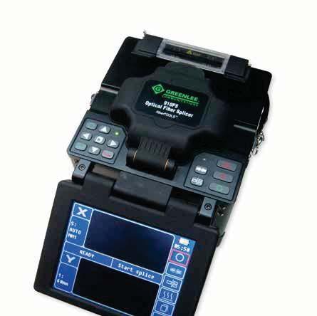
6 Optical Fusion Splicer Introduction The 910FS Core Alignment fusion splicer provides lower loss fusion splices than cladding or V-groove technology fusion splicers. The active alignment mechanism of the 910FS Core Alignment splicer makes adjustments to compensate for concentricity, dirt and overall diameter. Single Mode Fibre (SMF) has a core diameter of between 8 and 10 microns but if the core and cladding is not co-axial, a mechanical alignment of the cladding (in V-grooves) can not optimally align the cores in two dimensions; Resulting in higher splice losses. Core Alignment Technology The 910FS Core Alignment fusion splicer employs a Core Detection System (CDS) also known as a Profile Alignment System (PAS). Light is shone into the fibre and embedded cameras are used to identify the core of the fibre by detecting the difference in the refraction of light caused at the core/cladding interface. The type of fibre is also determined at this stage and allows the 910FS fusion splicer to automatically select the optimum splicing profile. Core alignment splicers use six motors and two cameras to align the fibres in the X, Y and Z dimensions. The motors then bring the fibres together in the Z direction prior to splicing. The 910FS Core Alignment Splicer is able to compensate for any misalignment of the fibre cores held in the V-grooves since the V-grooves are moved to align the cores of both fibres precisely. This is done in a dynamic feedback loop (PAS) methodology that automatically senses the active area of the fibre core and adjusts the alignment of the two cores to minimise loss. Any misalignment of the fibres within the V-grooves, due to fibre tolerances, contamination or misuse is automatically compensated resulting in repeatable, low loss splices. 910CL & 915CL Optical Fibre Cleaver Cleaves Single-Mode and Multi-Mode Fibre Transferable Adaptors available for 250, 900μm, Bow-Tie & Splice-On-Connector (SC, ST, FC and LC) Fixed Adaptor option available Blades rotate for long life No batteries or power required Fibre Sharps Bin CL Optical Fibre cleaver CL Optical Fibre cleaver (supplied with fixed clamp) FS μm Adaptor (PAIR-FH-250) FS μm Adaptor (PAIR-FH-900) FS-3MM Adaptor 3mm (910FS) FS-LT LT-900 Loose tube Fibre Adaptor PA1171 Fibre Stripper PA1511 Kevlar Scissors CL-BLADE Cleaving wheel CL-CLAMP Fixed Clamp SPECIFICATIONS Fibre Type SM (G.652); MM (G.651); DS (G.653); NZDS (G.655); BIF (G.657) Fibre Cleaved Length 10mm Cladding Diameter 125μm Coating Diameter 250μm and 900μm (Primary & Secondary Coating) Fibre Count Single Cleaving Angle 0.5º Blade Rotation Positions 16 Blade Life 48,000 Cleaves Weight 255g Dimensions 58 x 55 x 48mm Splice-On-Connector Adaptors available (see page 7) 915CL with Cin Bin Fixed scale clamp Auto return blade 6
 Flip-Over LCD Screen True Core Alignment for Low Loss Splices Windows 10 compatible Auto-Check Fibre End Face Auto-Calculation of Estimated Splice Loss Selectable Heating Modes")
 52064142 910FS-900 900μm Adaptor (Pair) 52063416 910FS-PS Battery Charger (AC Mains transformer) 52063415 910FS-BATT Battery-Li Ion (910FS) 52064875 910FS-KIT1")
7 International Fibre Catalogue - Optical Fusion Splicer 910FS Optical Fusion Splicer 14.5cm (5.7 ) Flip-Over LCD Screen True Core Alignment for Low Loss Splices Windows 10 compatible Auto-Check Fibre End Face Auto-Calculation of Estimated Splice Loss Selectable Heating Modes Splice-On-Connector Options (SC, LC, ST & FC) Transferable or Fixed Fibre Adaptors (250, 900μm, 3mm) FS Optical Fusion Splicer FS-ELEC Replacement Electrodes FS μm Adaptor (Pair) FS μm Adaptor (Pair) FS-PS Battery Charger (AC Mains transformer) FS-BATT Battery-Li Ion (910FS) FS-KIT1 Contractor Fusion Splicer Kit 910FS Optical Fusion Splicer 910CL Optical Fibre Cleaver FS-KIT2 Contractor Fusion Splicer Kit 910FS Optical Fusion Splicer 910CL Optical Fibre Cleaver PA1171 Fibre Stripper Extra Rechargeable Li-ion Battery ACCESSORIES FS-SOC-SC-LC Splice-On-Connector Adaptor (SC & LC) FS-SOC-ST-FC Splice-On-Connector Adaptor (ST & FC) FS-EUR-CORD European Power Cord FS-CHARG 910FS Stand alone Battery Charger FS-UK-CORD UK Power Cord FS-TRAY Fusion Splice Tray (910FS) FS-CAR-ADAPTOR 12 V DC Vehicle Adaptor FS-3MM Adaptor 3mm (910FS) FS-LT LT-900 Loose tube Fibre Adaptor SPECIFICATIONS Applicable Fibres SM (G.652); MM (G.651); DS (G.653); NZDS (G.655); BIF (G.657) Fibre Cleaved Length 10mm Cladding Diameter 80 to 150μm Coating Diameter 100 to 1000μm Fibre Count Single Fibre Aligning Method Auto Core Alignment Splice Loss (Typical) 0.02dB (SM); 0.01dB (MM); 0.04dB (DS); 0.04dB (NZDS) Attenuated Splice Function 0.1dB 15dB Splicing Mode 60 Preset / User Definable Modes Splice Time (Typical) 9 seconds (SM) Splice-On-Connector LC, SC, ST and FC (see page 7) Arc Calibration Mode Automatic and Manual Protection Sleeve Length 60mm, 40mm, Micro Sleeves Storage of Splice Results 5000 Results Tension Test 2N Fibre Display Magnification 240x Tube Heating Mode Adjustable seconds Tube Heating Time (Typical) 36 seconds Display 5.7 Colour, Turn-Over LCD Electrode Life Burns Splices per Battery Charge 250 (60mm Shrink Cycles) Connectivity RS-232; USB Operating Conditions Pressure: 0 to 16,404 feet (0 to 5,000 meters) above Sea Level Humidity: 0 to 95% Temperature: 14 F to 122 F (-10 C to 50 C) Storage Conditions Temperature: -4 F to 158 F (-20 C to 70 C) Power Supply 100 to 240V AC Adaptor; Li-ion Battery (6600mAh) 12VDC Vehicle Charger Option Weight (Including Battery) 6.92lbs (3.14kg) Dimensions (HxWxD) 7.08 x 6.29 x 6.10 inch (180 x 160 x 155mm) 910FS 910FS-Kit 2 (with extra battery not shown) Top view of 910FS 7
 Auto-Check Fibre")
8 915FS Optical Fusion Splicer Auto-Calculation of Estimated Splice Loss Active Cladding Technology Alignment Selectable Heating Modes Splice-On-Connector Options (SC, LC, ST & FC) Auto-Check Fibre End Face Transferable or Fixed Fibre Adaptors (250, 900μm) Loose Tube to SOC Capable IP 52 PART No. DESCRIPTION Fusion Splicer Kit Optical Fusion Splicer Replacement Electrodes μm Adaptor (Pair) μm Adaptor (Pair) Adaptor 3mm 910FS Battery-Li Ion (915FS) Battery Charger (AC Mains transformer) Instruction Manual Electrode Cleaner Contractor Fusion Splicer Kit - 915FS-KIT1 915FS Fusion Splicer Kit 915CL Optical Fibre Cleaver Contractor Fusion Splicer Kit - 915FS-KIT2 915FS Fusion Splicer Kit 915CL Optical Fibre Cleaver 5 in 1 Fibre Stripper Extra Rechargeable Li-Ion Battery ACCESSORIES Splice-On-Connector Adaptor (SC & LC) Splice-On-Connector Adaptor (ST & FC) European Line Cord UK Line Cord V DC Car Adaptor LT-900 Loose Tube Fibre Adaptor SPECIFICATIONS Applicable Fibres SMF (ITU-T G.652), MMF (G.651), DSF (G.653), NZDSF (G.655), BIF (G.657), EDF Fibre Cleaved Length 8 to 16mm (Coating dia: 0~250μm); 16mm (Coating dia. 250 ~ 1000μm) Cladding Diameter 80 to 150μm Coating Diameter 100 to 1000μm Fibre Count Single Fibre Aligning Method V Groove Alignment Splice Loss (Typical) SMF/BIF 0.02dB/ MMF 0.01dB / DSF/NZDSF/EDF 0.04dB(typical) Attenuated Splice Function 0.1 to 15 db Splicing Mode Arcing / 60 modes Splice Time (Typical) 9 seconds (SM) Splice-On-Connector LC, SC, ST and FC (see page 9) Arc Calibration Mode Automatic and Manual Protection Sleeve Length 60mm, 40mm, Micro Sleeves Storage of Splice Results 5000 Results/100 screen shots Tension Test 2N Fibre Display Magnification Dual CMOS Cameras 200x Tube Heating Mode Adjustable seconds Tube Heating Time (Typical) 36 seconds Display 87.5mm (3.5 ) Colour, Turn-Over LCD Electrode Life 5000 Burns Splices per Battery Charge Splice & Heating Cycles Connectivity USB Operating Conditions Altitude: 0 to 5000m,Wind Speed 15m/s Humidity: 0 to 90% Temperature: -25 C to 50 C Storage Conditions Temperature: -30 C to 70 C Power Supply AC/DC Power Adaptor (50/60Hz) 110~240V, 4400mAhLithium Battery 12VDC Vehicle Charger Option DC 14.5~15V Weight (Including Battery) 1.2kg (2.6lbs) (without battery) / 1.5kg (3.3lbs) (with battery) Dimensions (HxWxD) mm (4.9 x 4.9 x 5.3 ) (L W H) 8

9 International Fibre Catalogue - Optical Fusion Splicer Splice on Connectors PART No. CAT. No. QTY DESCRIPTION QTY CAT. No. PART No SC/APC Singlemode, Green 900μm Boot SC/UPC Singlemode, Blue 900μm Boot SC/PC 62.5μm Multimode (OM1), Beige 900μm Boot SC/PC 50μm Multimode (OM2), Black 900μm Boot SC/PC 50μm Multimode (OM3), Aqua 900μm Boot SC/PC 50μm Multimode (OM4), Aqua 900μm Boot FC/APC Singlemode, Green 900μm Boot FC/UPC Singlemode, Blue 900μm Boot FC/PC 62.5μm Multimode (OM1), Beige 900μm Boot FC/PC 50μm Multimode (OM2), Black 900μm Boot FC/PC 50μm Multimode (OM3), Aqua 900μm Boot FC/PC 50μm Multimode (OM4), Aqua 900μm Boot ST/UPC Singlemode, Blue 900μm Boot ST/PC 62.5μm Multimode (OM1), Beige 900μm Boot ST/PC 50μm Multimode (OM2), Black 900μm Boot ST/PC 50μm Multimode (OM3), Aqua 900μm Boot ST/PC 50μm Multimode (OM4), Aqua 900μm Boot LC/APC Singlemode, Green 900μm Boot LC/UPC Singlemode, Blue 900μm Boot LC/PC 62.5μm Multimode (OM1), Beige 900μm Boot LC/PC 50μm Multimode (OM2), Black 900μm Boot LC/PC 50μm Multimode (OM3), Aqua 900μm Boot LC/PC 50μm Multimode (OM4), Aqua 900μm Boot LC Type Splice on Connector SC Type Splice on Connector FC Type Splice on Connector ST Type Splice on Connector SOC ADAPTORS AFL/Fujikura SOC Adaptor Furakawa/Fitel SOC Adaptor Sumitomo SOC Adaptor INNO SOC Adaptor FIS Super Cougar SOC Adaptor Designation Fibre Type Jacket Colour Bandwidth Multi-mode Fibre 850 nm / 1310 nm Multi-mode Optics (MMF) MAX Length 1GB/s 10 Gb/s 40/100 Gb/s OM1 62.5/125 Orange 200 MHz/km / 500 MHz/km SX, SR, LX*, LRM* 300m 984ft 30m 98ft NA OM2 50/125 Orange 500 MHz/km / 500 MHz/km SX, SR, LX*, LRM* 600m 1968ft 150m 492ft NA OM3 50/125 Aqua 1500 MHz/km / 500 MHz/km SX, SR, LRM, LX4 1000m 3280ft 300m 984ft 100m 328ft OM4 50/125 Aqua / Magenta 3500 MHz/km / 500 MHz/km SX, SR, LRM, LX4 1100m 3608ft 550m 1804ft 150m 492ft 9

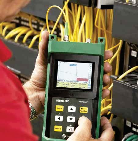
10 Fibre Fault Locators - OTDRs 930XC Handheld Multimode OTDR 850/1300nm wavelength Up to 24dB SWDR Optical Power Meter Stabilised Light Source Visual Fault Locator Fibre analysis software for report generation Large backlight LCD colour display RS-232/USB interface NiMH batteries for 8 hours continuous use Software compatible to Win. XP, 7, 8, 8.1,10 Multiple languages Pass/Fail thresholds Event table Insertion loss Return loss XC-20M-FC Multimode OTDR W/FC Bulkhead XC-20M-SC Multimode OTDR W/SC Bulkhead XC-20M-ST Multimode OTDR W/ST Bulkhead 930XC Handheld Singlemode OTDR 2 & 3 wavelength options available: 1310/1550nm; 1310/1490/1550nm; 1310/1550/1625nm Up to 35dB SWDR on the 2 wavelength model Up to 38dB SWDR on the 3 wavelength model Optical Power Meter Stabilised Light Source Visual Fault Locator Fibre analysis software for report generation Large backlight LCD colour display Measure length and defects of coiled fibre 1625nm operation for live fibre testing (30F) RS-232/USB interface NiMH batteries for 8 hours continuous use Multiple languages Pass/Fail thresholds Event table Insertion loss Return loss Dual Wavelength Singlemode OTDR XC-20C Singlemode OTDR, 1310/1550nm FC/UPC XC-20C Singlemode OTDR, 1310/1550nm SC/UPC XC-20C Singlemode OTDR, 1310/1550nm ST/UPC XC-20C Singlemode OTDR, 1310/1550nm FC/APC XC-20C Singlemode OTDR, 1310/1550nm SC/APC Triple Wavelength Singlemode PON OTDR XC-30P Singlemode OTDR, 1310/1490/1550nm FC/UPC XC-30P Singlemode OTDR, 1310/1490/1550nm ST/UPC XC-30P Singlemode OTDR, 1310/1490/1550nm SC/UPC XC-30P Singlemode OTDR, 1310/1490/1550nm FC/APC XC-30P Singlemode OTDR, 1310/1490/1550nm SC/APC 930XC Complete FTTH maintenance tool includes; - Optical Power Meter - Stabilised Light Source - Visible Fault Locator Triple Wavelength Singlemode Filtered OTDR XC-30F Singlemode OTDR, 1310/1550/1625nm FC/UPC XC-30F Singlemode OTDR, 1310/1550/1625nm SC/UPC XC-30F Singlemode OTDR, 1310/1550/1625nm ST/UPC XC-30F Singlemode OTDR, 1310/1550/1625nm FC/APC XC-30F Singlemode OTDR, 1310/1550/1625nm SC/APC 930XC OTDR ACCESSORIES XC Carry Case FC Bulkhead Connector (For UPC & APC) ST Bulkhead Connector (For UPC & APC) SC Bulkhead Connector (For UPC & APC) Power Supply, Universal Vehicle adaptor (5.5 Outer Diameter, 2.1Inner Diameter) USB Cable for OTDR RS-232 Cable NIMH Battery (9.6V) 10
 35 38/37/37 38/37/37 21/24 Event Deadzone (m) 1.0 1.0 1.0 2.5 Attenuation Deadzone (m) 4.5 4.5 4.5 12 Pulsewidth (ns) 5, 10, 30, 100, 300, 1μs, 2.")
11 International Fibre Catalogue - Fibre Fault Locators - OTDRs Greenlee s OTDR Range Characteristics SPECIFICATIONS 930XC-20C 930XC-30F 930XC-30P 930XC-20M Wavelength (± 20nm) 1310/ /1550/ /1490/ /1300 Dynamic Range (db) 35 38/37/37 38/37/37 21/24 Event Deadzone (m) Attenuation Deadzone (m) Pulsewidth (ns) 5, 10, 30, 100, 300, 1μs, 2.5μs, 10μs, 20μs 12, 30, 100, 275, 1μs, 2μs Selectable Ranges (km) 0.3, 1.3, 2.5, 5, 10, 20, 40, 80, 120, 160, , 0.3, 0.5, 1.3, 2.5, 5, , 0.3, 0.5, 1.3, 2.5, 5, 10, 20, 40, 80 Sampling Points 16,000 (Maximum) 16,000 (Maximum) Average Time 15s/30s/1 min/2 min/3 min Distance Measurement Accuracy ±(1m + 5 x 10⁻⁵ x distance + sampling space) Connector Type PC or APC (interchangeable FC, SC, ST) Reflection Detect Accuracy ±4 db Attenuation Detect Accuracy ±0.05 db/db Measurement Data Storage 1,000 test curves Data Transmission RS-232/USB port Visual Fault Locator (VFL) 3mW; 650nm Optical Power Meter (OPM) InGaAs OPM Wavelengths 850, 1300, 1310, 1490, 1550, 1625nm OPM Range +6 to -70dBm (+6 to 850nm) OPM Display resolution 0.01dB OPM MOD Identification 1kHz, 2kHz Stabilized laser Source (SLS) Wavelength same as selected in OTDR mode -7dBm Power Supply NiMH chargeable battery/ac adaptor Battery Life Support over 8 hours operating on one charge or over 20 hours standby Operating Temperature -10 C to 50 C Storage Temperature -20 C to 60 C Relative Humidity 0 to 95% (non-condensing) Weight 1.9lbs. (0.87kg) Dimensions 7.7 H x 3.9 W x 2.4 L (196mm x 100mm x 64mm) Compliance BelCore GR196, CE, FCC, UL, RoHS, WEEE Fibre Analysis Software Version 3.2 TraceViewer Software 45km trace with Event Table 11

 + MM (UPC) Kit - (SM & MM OTDR Kit) Select appropriate patch cord to match your OTDR port. Either xx/upc or xx/apc.")
 Long battery life (13,000 tests on 4 AA batteries) ST output connection")
12 Singlemode & Multimode OTDR Kit Combines 930XC SM and MM OTDRs in 1 kit 850/1300nm & 1310/1550nm FC, ST and SC Adaptors included Compact handheld design Easy to use Fast automated testing Up to 24dB dynamic range on MM and up to 35dB range on SM Large backlight LCD display Measure length and defects on SM & MM fibre Fibre analysis software for data management & report generation RS-232/USB interface NiMH batteries for 8 hours continuous use XC-SM (APC) + MM (UPC) Kit - (SM & MM OTDR Kit) Select appropriate patch cord to match your OTDR port. Either xx/upc or xx/apc. MicrOTDR Optical Fault Locator Measure cable length to 20km Singlemode and multimode operation Identify distance to 7 loss points/faults Distance accuracy of +/- 2 metres Check fibre reels for length and defects Troubleshoot installed fibre Easy to use Fast Operation (<6 seconds to find 6 events plus the end of fibre) Long battery life (13,000 tests on 4 AA batteries) ST output connection Accurate ID of loss points & length for SM & MM fibres MicrOTDR Optical Fault Locator SPECIFICATIONS. MicrOTDR Centre Wavelengths 1310nm Emitter Type Laser (Class 1) Connector Type ST Pulse Widths 200ns Typical Pulse Rate 500kHz Emitter Fibre Type Multimode & Singlemode Index of Refraction (GIR) 1.40 ~1.69 End of measurement Accuracy ±2m + IOR Variation (IOR Variation = 0.67m/km per.001 IOR error) Minimum Distance Measured 30m Dead Zone 30m Maximum Distance Measured 20km Minimum Detectable 10km -49dB Number of Events Detected 7 Operating Temperature -10 C to 50 C Storage Temperature -20 C to 60 C Relative Humidity 0 to 95% RH (non-condensing) POWER Battery Life (Alkaline) 13,000 tests PHYSICAL Size 195mm x 100mm x 45mm (7.7 x 3.9 x 1.7 ) Weight 0.44kg (0.9lbs) 12


13 International Fibre Catalogue - Fibre Fault Locators - OTDRs Launch Cable LC-500 Universal compact design 500m SM fibre 1m patch cord supplied Rugged construction Adapt between APC & UPC connectors BENEFITS Troubleshoot the input connector and the initial fibre span that may be masked by the deadzone of an OTDR Characterise input and output connectors and the entire fibre link Minimise Dead zones Eliminate multiple patch cables LC m Launch cable LC-500 with 1m SC/PC-SC/PC patch cable PATCH CORDS AVAILABLE SCUPC-SCUPC Fibre Cable SC/UPC SC/UPC 1m 9/125/3MM SCUPC-LCUPC Fibre Cable SC/UPC LC/UPC 1m 9/125/3MM FCUPC-FCUPC Fibre Cable FC/UPC FC/UPC 1m 9/125/3MM SCAPC-LCAPC Fibre Cable SC/APC LC/APC 1m 9/125/3MM STUPC-STUPC Fibre Cable ST/UPC ST/UPC 1m 9/125/3MM SCAPC-LCUPC Fibre Cable SC/APC LC/UPC 1m 9/125/3MM SCPC-SCPC Fibre Cable SC/UPC SC/UPC 1m 62.5/125/3MM FCUPC-FCAPC Fibre Cable FC/UPC FC/APC 1m 9/125/3MM FCPC-FCPC Fibre Cable FC/UPC FC/UPC 1m 62.5/125/3MM FCUPC-LCUPC Fibre Cable FC/UPC LC/UPC 1m 9/125/3MM STPC-STPC Fibre Cable ST/UPC ST/UPC 1m 62.5/125/3MM FCUPC-LCAPC Fibre Cable FC/UPC LC/APC 1m 9/125/3MM SCPC-SCPC/50 Fibre Cable SC/UPC SC/UPC 1m 50/125/3MM FCAPC-LCAPC Fibre Cable FC/APC LC/APC 1m 9/125/3MM FCPC-FCPC/50 Fibre Cable FC/UPC FC/UPC 1m 50/125/3MM FCAPC-LCUPC Fibre Cable FC/APC LC/UPC 1m 9/125/3MM STPC-STPC/50 Fibre Cable ST/UPC ST/UPC 1m 50/125/3MM SCUPC-FCAPC Fibre Cable SC/UPC FC/APC 1m 9/125/3MM SCAPC-SCAPC Fibre Cable SC/APC SC/APC 1m 9/125/3MM SCAPC-FCUPC Fibre Cable SC/APC FC/UPC 1m 9/125/3MM FCAPC-FCAPC Fibre Cable FC/APC FC/APC 1m 9/125/3MM SCPC-FCPC Fibre Cable SC/UPC FC/UPC 1m 62.5/125/3MM SCUPC-SCAPC Fibre Cable SC/UPC SC/APC 1m 9/125/3MM SCPC-FCPC 50UM Fibre Cable SC/UPC FC/UPC 1m 50/125/3MM SCUPC-LCAPC Fibre Cable SC/UPC LC/APC 1m 9/125/3MM OTDR trace with LC-500 at start & end of Fibre under Test. Enables accurate measurement of end connectors. 13


 port. 10M to 1G Ethernet - 8 streams RFC-2544 & Y.1564 E1, E3, T1, T3 C37.")
14 Multi-Service Network Analysers DataScout DS1G The DataScout 1G is a multi-service handheld tester capable of testing Gigabit Ethernet, Y.1588v2, IPTV, VoIP, WiFi, and legacy DS-1/DS-3/Datacom transport services and more. The extended runtime battery and fanless design enable the DataScout to perform continuous testing on battery power for up to 8 hours without recharging. The tool includes a two taps to test user interface and green means go, red means stop pass/fail indication testing. Results are automatically stored via the 4 GB internal flash memory. Greenlee says the DataScout 1G helps to ensure business services are provisioned correctly at the time of installation, which reduces truck rolls. Additionally, the company says operational expenses are reduced because of the low learning curve for technicians. During field trials with major carriers, technicians new to network testing were quickly proficient using the DataScout 1G with little to no training. DS1G can support Fibre presented network protocols via Optical SFP (1000-Base-X) port. 10M to 1G Ethernet - 8 streams RFC-2544 & Y.1564 E1, E3, T1, T3 C37.94 Teleprotection (SCADA) IPTV testing Remote control via VNC Layer 1-4 BERT Transport Testing CODIR, DATACOM Wi-Fi testing VoIP testing - HARDWARE OPTIONS DS1G-BAS DataScout 1G Ethernet Analyser Kit (includes DS1G-SW-BAS) DS1G-PDH1 DataScout 1G Ethernet & T1/E1 Analyser Kit (includes DS1G-SW-T1 or E1) DS1G-PDH2 DataScout 1G Ethernet, T1/E1 & T3/E3 Analyser Kit (includes DS1G-SW-T3 or E3 & DS1G-SW-T1 or E1) - SOFTWARE OPTIONS DS1G-SW-BAS Basic Ethernet BERT/LOOPBACK/RFC-2544 Analysis DS1G-SW-ADV Advanced Ethernet Multi-Stream & Y.1564 Analysis (requires DS1G-SW-BAS) DS1G-SW-VOIP VOIP (SIP) Live Calling & Analysis DS1G-SW-IPTV IPTV TR Alarm & Stream Analysis DS1G-SW-WIFI WIFI B/G/N Analysis DS1G-SW-E1 E1 BERT/PDL/Pulse Mask Errors/Alarms Analysis (requires DS1G-PDH1 or PDH2) DS1G-SW-CODIR CODIR Sub rate analysis requires PDH 1 hardware DS1G-SW-T1 T1 BERT/PDL/Pulse Mask Errors/Alarms Analysis (requires DS1G-PDH1 or PDH2) DS1G-SW-DCOM DATACOM Sub rate analysis requires PDH 1 hardware DS1G-SW-E3 E3 (requires DS1G-PDH2) DS1G-SW-T3 T3 (requires DS1G-PDH2) DS1G-SW-C37 IEEE C Analysis Contact Sales for software options. DS1G displaying software options. Licences can be purchased to enable services. SFPS SUPPORTED DS-SFP-MMF-SX SFP-1000 BASE-X-SX 850nm Multimode Transceiver DS-SFP-SMF.LX SFP-1000 BASE-X-LX 1310nm Singlemode Transceiver DS-SFP-SMF-ZX SFP-1000 BASE-X-ZX 1550nm Singlemode Transceiver DS-SFP-MMF-C37 SFP- 2MBPS 850nm Multimode Transceiver (2KM) C
 Wireless Validation DS3 Testing DS1 Testing Signaling (TIMS/DS0) Testing Intelligent Timing Verification Datacom Testing 4 Wire DDS Testing CONTROLLER OPTIONS CAT. No.")


15 International Fibre Catalogue - Multi-Service Network Analysers DS10G DataScout Multi-Service Network Analyser Ethernet Validation Conformance to SLA: Throughput, Latency, Frame Loss, Burst (b, g, n) Wireless Validation DS3 Testing DS1 Testing Signaling (TIMS/DS0) Testing Intelligent Timing Verification Datacom Testing 4 Wire DDS Testing CONTROLLER OPTIONS CAT. No. DS10G-HW-B1 DS10G-HW-B2 DS10GX-HW-B1 DS10GX-HW-B2 DESCRIPTION Base Controller Without Datacom Interface Base Controller With Datacom Interface Headless Base Controller Without Datacom Interface Headless Base Controller With Datacom Interface DS10G TEST INTERFACE OPTIONS Ethernet Option DS10-HW-ETH Wi-Fi Option DS10-HW-WIFI Transport Options DS10-HW-PDH1 DS10-HW-PDH2 DS10-HW-P DS10-HW-DDS TIMS Test Option DS10-HW-T RITS Test Option DS10-HW-RITS Dual Port to 10G Ethernet WI-FI Test & Remote Control Interface Dual Port DS1 Test Interface DS3 & Dual Test Interface ISDN-PRI Test Interface DDS Test Interface TIMS Test Interface Intelligent DS1 Clock & Timing Analysis Interface SOFTWARE OPTIONS CAT. No. Ethernet Test Options DS10G-SW-201 DS10G-SW-110 DS10G-SW-210 DS1 Test Options DST-SW-DT1 DST-SW-N1 DST-SW-X DST-SW-DCOM DST-SW-E1 DS3 Test Options DST-SW-H3 DST-SW-D1D DST-SW-NX PRI Test Options DST-SW-E TIMS Test Options DST-SW-PRO4 DST-SW-4 DST-SW-EM DST-SW-DG DST-SW-SS DST-SW-TON DST-SW-DVM DST-SW-SSM Remote Control Option DS10-SW-RC DESCRIPTION Dual Port 10G Ethernet Testing Single Port 10G Test Interface Adds Dual port 1Gb Ethernet testing Enables Dual Port T1 Testing EnablesT1 CSU/NIU Emulation Enables DS0 Drop & Insert Bypass Enables DTE/DCE Interface Testing Enables E1/T1 on-the-fly Testing Adds DS3 Thru-Mode Testing Adds DS1 Drop from DS3 Signal Adds DS3 CSU/NIU emulation Euro/Asian ISDN-PRI Support Adds 4-Button Custom Frequency Program Adds 4-Wire 100/135Ω Testing Adds E&M Type I-V Signaling, Trunk, PBX & Tie Line Testing Adds Measurement of Dropouts, Hits, Amplitude and Phase Jitter Adds Selective Signaling Adds Transmit of Warble ID-Tone Enables Digital Volt Meter Enables Synch Status Message Decode on T1 / E1 Signals Remote Control Via LAN or Wi-Fi DS10Gx TMC Award Winner!! Tablet not included Fully equipped platform. Unused ports can be blanked off. 15
 Referenced & Absolute optical power readings Stores up to 1000 measurements per wavelength Download results via USB (GRP460 only) Audible tone alert from incoming 2kHz")


16 Greenlee Mini Fibre Tools Optical Power Meters (OPM) Referenced & Absolute optical power readings Stores up to 1000 measurements per wavelength Download results via USB (GRP460 only) Audible tone alert from incoming 2kHz signal Various connector options available NIST traceable measurements Multimode and Singlemode operation Long battery life Rugged and compact size Conversion to Live Fibre ID with GLFI , 1310, 1490, 1550nm calibrated wavelengths Windows 10 compatible GRP OPM, Germanium, 0.01dB, db/dbm GRP OPM, InGaAs, 0.01dB, db/dbm GRP OPM, Filtered InGaAs, 0.01dB, db/dbm GRP OPM, Germanium, 0.01dB, db/dbm w/memory GRP OPM, InGaAs, 0.01dB, db/dbm w/memory GRP OPM, Filtered InGaAs, 0.01dB, db/dbm w/memory GRP OPM, Germanium, 0.01dB, db/dbm, Memory & PC GRP OPM, InGaAs, 0.01dB, db/dbm, Memory & PC GRP OPM, Filtered InGaAs, 0.01dB, db/dbm, Memory & PC CONNECTOR OPTIONS GAC mm Universal Adaptor for OPM GAC mm Universal Adaptor for OPM GAC026 SC Adaptor for OPM GAC027 ST Adaptor for OPM GAC028 FC Adaptor for OPM GAC029 LC Adaptor for OPM Single Instrument, Belt-Mounted Carry Pouch GAC126 SC/APC Adaptor for OPM GAC540 Opti Tap Patchcord SC/APC for OPM SPECIFICATIONS db/dbm GRP GRP GRP On-board storage GRP GRP GRP Data transfer to PC GRP GRP GRP Detector type Ge InGaAs Filtered InGaAs Wavelength range 850nm to 1625nm Measurement range +3 to 60dBm +3 to 70dBm +23 to 45dBm Resolution 0.01dB Absolute accuracy +/- 0.25dB Optical interface Universal 2.5mm (Order 1.25mm or screw on adaptors separately) Tone identification 2kHz Incoming signal, Audible Alert Power on Push button ON, Auto shutoff Storage Store up to 1000 measurements/wavelength GRP 455 & 460 Data transfer Mini USB Port (1000 points/wavelength) GRP 460 ONLY Dimensions 6.1 x 0.94 x 0.75in. (15.5 x 2.38 x 1.90cm) Weight 3.0oz (85g) Greenlee OPM Data Manager software is available for download from the dedicated Greenlee website at (available for use with GRP460 OPM only) SC ST LC FC OptiTap Example of Test Report 16
* 52060850")
17 International Fibre Catalogue - Greenlee Mini Fibre Tools Optical Light Sources (OLS) Dual- and Single- Wavelength options Stable, calibrated output NIST Traceable Multimode and Singlemode wavelength options FB version compatible with LC connectors 2kHz Tone output Long Battery Life Rugged and compact size GDLS350FB 850/1300nm Dual LED Source (Supplied with SC Adaptor)* GDLS355FB 1310/1550nm Dual Laser Source (Supplied with SC Adaptor)* GDLS360FB 1490/1625nm Dual Laser Source (Supplied with SC Adaptor)* GDLS /1300nm Dual LED Source (Supplied with SC Adaptor)* GDLS /1550nm Dual Laser Source (Supplied with SC Adaptor)* GTP nm LED Source - Fixed ST Female Adaptor GTP nm VCSEL Source - Fixed SC Male Adaptor GTP nm Laser Source - Fixed SC Male Adaptor GTP nm LED Source - Fixed ST Female Adaptor GTP nm Laser Source - Fixed SC Male Adaptor GTP nm Laser Source - Fixed SC Male Adaptor CONNECTOR OPTIONS GAC022B SC Adaptor for FB Version GAC023B FC Adaptor for FB Version GAC024B ST Adaptor for FB Version GAC025B LC Adaptor for FB Version GAC022 SC Adaptor for OLS - GDLS 350 & GDLS GAC023 FC Adaptor for OLS - GDLS 350 & GDLS GAC024 ST Adaptor for OLS - GDLS 350 & GDLS Single Instrument, Belt-Mounted Carry Pouch *Please see below for available adaptors SC ST LC FC GDLS350FB GDLS355FB GDLS360FB GTP210 GTP230 GTP220 GTP250 GTP240 Wavelength 850nm 1300nm 1310nm 1550nm 1490nm 1625nm Output Power -20dBm Typ. -4.0dBm Typ. -4.0dBm Typ. Laser Classification LED Class 1 (FDA 21 CFR 1040, 11) Class 1 (FDA 21 CFR 1040, 11) Output Stability +/- 0.05dB after 15 minutes, + /- 0.03dB after 1 hour warm-up Spectral Width 40nm/120nm 5nm/5nm 5nm/5nm Optical Interface Universal Connector Interface (FC, SC, ST & LC) - LC only on FB versions Tone Output 2kHz Power On Push Button ON, Auto Shut-off Battery CR2 (battery charger available) Dimensions 6.1 x 0.94 x 0.75in (15.5 x 2.38 x 1.90cm) Weight 3oz (85g) Operating Temperature -10 C to 50 C Storage Temperature -30 C to 60 C 17


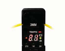
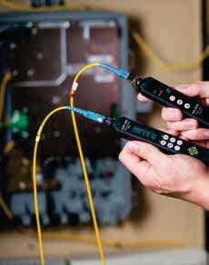
18 Live Fibre Identifier FI-100 Low insertion loss - Non-intrusive, low insertion loss will not drop signal Easy operation - Identifies fibre with tone detect and a clear indication of signal transmission direction Versatile - Supports all common fibres including 250μm, 900μm, 2mm, and 3mm and is able to sense light in bend insensitive fibres Part No. CAT No. DESCRIPTION FI-100 KIT Fibre Identifier Kit FI μm 250μm Adaptor FI μm 900μm Adaptor FI-100-2mm 2mm Adaptor FI-100-3mm 3mm Adaptor FI-100-Case Soft Carry Case FI-100-Sunshade Sun Shade SPECIFICATIONS Identified Wavelength Range nm Identified Signal Type 270Hz ±5%, 1kHz ±5%, 2kHz ±5% Detector Type 1mm InGaAs Adaptor Types 250μm (Applicable for Bare Fibre) 900μm (Applicable for 900μm Secondary Coated Fibre) 2mm (Applicable for 2mm Jacketed Cable) 3mm (Applicable for 3mm Jacketed Cable) Signal Indication Left & Right LED Signal Direction Test Range (CW/900μm fibre) -46 to +10dBm (1310nm) -50 to +10dBm (1550nm) Signal Power Test Range (CW/900μm fibre) -50 to +10dBm Signal Frequency Display 270Hz, 1kHz, 2kHz Tone Detect Test Range (Average) -30 to 0dBm (270Hz, 1kHz) 900μm, 2mm, 3mm -25 to 0dBm (2kHz) μm Insertion Loss (Typical/Maximum) 0.3 / 0.8dB at 1310nm 1.5 / 2.5dB at 1550nm Battery AAA Alkaline (2) Operating Temperature -10 to +60ºC Storage Temperature -25 to +70ºC Dimension 196 x 30.5 x 27mm Weight 195g Certifications CE, FCC, WEEE ACCESSORIES FI-100 KIT contains instruction manual, sun shade and two AAA batteries. -25 to 0dBm (1kHz, 2kHz) -20 to 0dBm (2kHz) 2015 Diamond Technology Reviews FI-100 Fibre Identifier The FI-100 Fibre Identifier measures core power in a fibre optic cable. Fibre is inserted into the fibre adaptors, and the clamping mechanism causes a macrobend to be impressed upon the fibre. Two photodiodes measure the small portion of light that is spilled out of the fibre. The FI-100 is able to measure the direction of light travel and can positively identify fibres using 270 Hz, 1 khz, or 2 khz tone detect frequencies. Precision fibre adaptors for each fibre size introduce the exact amount of mechanical bend in the fibre without causing excessive loss. Technicians can probe fibres to identify which are active before disconnecting. This prevents the disconnection of a fibre that is being used for a critical service. The precise fibre adaptors also make the FI-100 well-suited for bendinsensitive fibre, Greenlee says. Fibre tracing allows the technician to identify a fibre when a tone is injected into it with a complementary laser source. The other end of the fibre can be located without disconnecting each fibre in a pedestal or cabinet that houses multiple fibres.


19 International Fibre Catalogue - Greenlee Mini Fibre Tools Visual Fault Locator 180XL LOCATING BREAKS AND BENDING LOSSES The 180XL visual fault finder is an indispensable tool for quickly identifying bending losses and breaks in optical fibres. If a fibre is bent too tightly, red laser light will be seen escaping through the jacket. Likewise, if a fibre is broken, escaping light will be visible where the break is located. IDENTIFYING BAD CERAMIC CONNECTORS Ceramic connectors are easily tested using the 180XL visual fault finder. A fibre broken inside, or past, the ferrule will cause it to glow, as shown below at left. If the whole connector glows, it is definitely defective. If the end face polish of the connector is bad, light will be reflected internally, as shown below right. This will also make the ferrule glow when the 180XL is used. Fibre broken in ferrule Poor end face polish Continuous wave output mode for steady fault illumination Blinking output mode increases viewing contrast Easy to use Quick Connect interface fits all 2.5mm fibre optic connectors Ergonomic switch permits easy one-handed operation Simple, versatile, and user-friendly design Rugged, compact, and splash proof aluminium housing High output 1.0mW (0dBm) 650nm red laser Up to 7km range Two AA-size alkaline batteries provide 80 hours of continuous operation Nylon belt holster included XL Visual Fault Locator Kit (2.5mm UCI) XL mm adaptor SPECIFICATIONS Wavelength 650nm +/-10nm Emitter Type Fabry Perot Output Power 0dBm Spectral Width (CPR) <2nm Laser Classification 2 Range 7km Modes of Operation CW and 2Hz Modulation Method of Display Operation Red/Green LED Fibre Type Singlemode, Multimode Connector Interface 2.5mm Universal, Optional 1.25mm adaptor Battery AA (2) Battery Life 80 Hours with 3.9Wh batteries Weight 0.15lbs, (70g) (not including batteries) Dimensions 7.08 x 0.91 Dia (180mm x 23mm Dia) Operating Temperature -10 to +45C Storage Temperature -40 to +70C Certifications CE, WEEE, CDRH Reach RoHs 2.5mm 1.25mm adaptor Microbend easily visible in splice tray using 180XL 19


20 GMFT-SM Fibre Optic Test Set 1310/1550nm wavelengths Optical Power Meter Stabilised Laser Light Source >55dB dynamic range Easy to use Stores 1000 measurements per wavelength Fibre ID with modulating tone (audible & Visual) LCD display Fibre analysis software for report generation USB interface GMFT-SM Single Mode Kit Kit includes: 1-GDLS /1550 Dual Laser 1-GRP Optical Power Meter 1- Soft Carry Case GMFT-MM Fibre Optic Test Set 850/1300nm wavelengths Optical Power Meter Stabilised LED Light Source 40dB dynamic range Easy to use Stores 1000 measurements per wavelength Fibre ID with modulating tone (audible & Visual) LCD display Fibre analysis software for report generation USB interface GMFT-MM Multi Mode Kit Kit includes: 1-GDLS /1300 Dual LED 1-GRP Optical Power Meter 1- Soft Carry Case 20


 LCD display Fibre analysis")


21 International Fibre Catalogue - Greenlee Mini Fibre Tools GMFT-SM/MM Fibre Optic Test Set 850/1300/1310/1550nm wavelengths Optical Power Meter Stabilised Laser Light Source >55dB dynamic range-sm 40dB dynamic range-mm Easy to use Stores 1000 measurements per wavelength Fibre ID with modulating tone (audible & Visual) LCD display Fibre analysis software for report generation USB interface GMFT-SM-MM Single Mode/Multi Mode Kit Kit includes: 1-GDLS /1550 Dual Laser 1-GDLS /1300 Dual LED 1-GRP Optical Power Meter 1- Soft Carry Case Back to back measurement prior to Insertion Loss test 21
 Automatic or manual Pass/Fail analysis (IEC 61300-3-35) Field of View 800μm x 600μm USB connection to Laptop/PC Generate reports")
 Live - 800μm x 600μm Enlarge - 485μm x 365μm 630μm x 440μm Magnify and centre - 485μm x 365μm Resolution <1 micron ¾ micron Display screen size User defined 3.")

 180mm x 25mm x 19mm Probe 180mm x 25mm x 19mm / Monitor 120mm x 89mm x 32mm Weight (Probe) 102g 540g (Probe, monitor")
22 Video Inspection System - GVIS400HDP (Digital Video Inspection) Automatic or manual Pass/Fail analysis (IEC ) Field of View 800μm x 600μm USB connection to Laptop/PC Generate reports High Definition Image Hands-free voice commands (Windows Vista, 7 and above) Magnify and centre Stream power measurements from GRP Digital archiving SPECIFICATIONS GVIS400HDP GVIS300 FOV (Field of View) Live - 800μm x 600μm Enlarge - 485μm x 365μm 630μm x 440μm Magnify and centre - 485μm x 365μm Resolution <1 micron ¾ micron Display screen size User defined 3.5in (90mm) diagonal Battery Life N/A 8 to 10hrs continuous Battery charge time N/A 3 hours Operating Temp. 0 C to 50 C 0 C to 50 C Storage Temp. -40 C to 70 C -40 C to 70 C Optical Magnification 135x, 200x 135x, 200x Camera type HD Megapixel CMOS sensor HD Megapixel CMOS sensor Pass/Fail analysis User selectable or IEC software included Engineer decides Pass/Fail criteria Focus control External Focus System External Focus System Cord Length 44cm - 100cm 44cm - 100cm Connector USB 2.0 USB 2.0 Light Source White LED Blue LED Lighting Technique Coaxial Coaxial Size (Probe) 180mm x 25mm x 19mm Probe 180mm x 25mm x 19mm / Monitor 120mm x 89mm x 32mm Weight (Probe) 102g 540g (Probe, monitor and case) Greenlee GVIS Image Management Software (for use with the GVIS300 and GVIS400HDP Visual Inspection System) also allows for data streaming of OPM loss measurements (available for use with GRP OPM only). Greenlee Image Management System software being available for download from the dedicated Greenlee website at Figure 1 Image showing automatic Pass/Fail analysis software Figure 2 Image showing manual analysis software 22


23 International Fibre Catalogue - Greenlee Mini Fibre Tools Video Inspection System - GVIS300 ¾ μm scratch resolution Unique focussing mechanism eliminates need for focus wheel 135x magnification Thin (less than 2.5cm dia.) ergonomic probe design FOV 630μm x 440μm 90mm LCD Display Rugged and compact size Quick change adaptor tips for all connector styles Li Ion Battery & smart technology AC charger system Optional Video Capture Module for digital archiving of the image Universal GVIS GVIS LC/PC GVIS400HDP GVIS300MP GVIS400HDP Probe with Auto Analysis Software, Carry Case, 10 x 1.25mm Swabs, 10 x 2.5mm Swabs, Cleaning Pen & SqR, 1.25mm, 2.5mm, SC & LC Adaptors GVIS 300 Monitor & Probe, 601C Carry Case, SC Bulkhead & 2.5mm Universal Adaptor, Battery Charger, Cleaning Pen & SqR GVIS300MP-USB GVIS 300 Monitor & Probe w/usb option, 601C Carry Case, SC Bulkhead & 2.5mm Universal Adaptor tips, Battery Charger, Cleaning Pen & SqR GVIS300P GVIS 300 Probe, 601C Carry Case, Instructions & 2.5mm Universal Adaptor GVCM410 USB Video Capture Module (For use with GVIS300P) GPAD 250 Wireless Portable Access Device E2000 Bulkhead FCPC Bulkhead GVIS MTP GVIS ST Adaptor ADAPTOR TIPS FOR GVIS PROBES GAC034B E2000 Bulkhead Adaptor GAC040B SC Bulkhead Adaptor GAC043B FC/APC Bulkhead Adaptor GAC041B SC/APC Bulkhead Adaptor GAC042B FC Bulkhead Adaptor GAC044B LC Bulkhead Adaptor GAC045B LC/APC Bulkhead Adaptor GAC046B ST Bulkhead Adaptor GAC047B MTP Mating Adaptor GAC048B 1.25mm Universal Connector GAC049B 2.5mm Universal Connector GAC100B ODC Plug Tip GAC101B ODC Socket Tip GAC104B 60º Angled GAC107B LC Bulkhead, 60º Angled GAC109B SC Bulkhead, 60º Angled GAC175B MTP/APC Bulkhead Adaptor GAC176B MTP/PC Bulkhead Adaptor GAC115B 2.5mm APC Universal Connector GAC116B 1.25mm APC Universal Connector GAC052B OptiTap SC/APC Adaptor OptiTap adaptor, used in FTTH applications LCPC SC APC SCPC GPAD Wi-Fi Portable Access Device Industry leading field of view Wireless transmission of db loss readings from the GRP PASS/FAIL via GPAD 250 conforming to IEC Compatible with Greenlee video inspection software Transmits live images and data via Wi-Fi from the GVIS 400-HDP via GPAD 250 USB Compatible with Apple & Android devices SPECIFICATIONS Dimensions Weight Wifi Connectivity Battery Battery Charger Communication Distance 114mm L x 38mm W x 70mm H 227g a,b,g,n, Wi-Fi Access Point 11.1 volt lithium ion, 4 hour battery life AC Wall pack 12.6 volt lithium ion charger 60m (GPAD 250 to wireless device) 23

24 XL fibertools Series Instruments Designed for POF & Fibre Optic Cable Testing The XL fibertools are designed for the professional to perform installation and maintenance measurements on both Plastic & Glass fibre optic networks. The instrument family consists of standard instruments for routine cable testing, through to Stabilised Light Sources with stringent Launch Conditions for the Avionics and Defence Industries and Research Laboratories. Greenlee s LED Light Sources have been manufactured with specific launch conditions to overcome the inconsistent measurements caused by standard Light Sources. The Multimode products that have specific launch conditions are designed for greater accuracy and repeatable results. Greenlee also manufacture instruments to test POF links. POF links are being used in a number of industries particularly on short links where optical budgets aren t too tight. The automotive industry is a good example of this. The XL fibertools are fully featured, general purpose fibre optic instruments, easy to operate and economically priced to outfit all technicians performing fibre optic installation and maintenance. Greenlee also manufacture a range of Optical Light Sources and Power Meters with enhanced EMI performance, manufactured to Military standards, these offer the ultimate in accuracy. Greenlee s range of Optical Light Sources and Power Meters were designed specifically for: avionics, automotive, defence and research. Optical Power Meters are available with different detectors. Choose between InGaAs, Si or Ge for operational wavelength. 560XL Fibre Optic Power Meter (Formerly 555B) Multi-Wavelength Storage 0.01dB measurement resolution Absolute (dbm) & Referenced (db) Power measurements Long battery life User selectable auto shut-off Rugged and splash-proof SOC interface adapts to all commonly used connectors.* Economically priced Easy to use - three buttons control all functions OPTICAL SPECIFICATIONS Detector Type Calibration Wavelengths Power Range Accuracy Resolution Power Requirements Connector Interface 1mm Indium Gallium Arsenide (InGaAs) 850nm, 1300nm, 1310nm and 1550nm +3dBm to -60dBm ±0.25dB 0.01dB Two AA 1.5V batteries (approx. 100 hours continuous operation) SOC ENVIRONMENTAL SPECIFICATIONS Calibration Wavelengths 850nm, 1300nm, 1310nm and 1550nm Power Range +3dBm to -60dBm Accuracy ±0.25dB Resolution 0.01dB Power Requirements Two AA 1.5V batteries (approx. 100 hours continuous operation) Connector Interface SOC Refer to p.33 for ordering information 24
 & Referenced (db) Power measurements Long battery life User selectable auto shut-off Rugged and splash-proof Economically priced SOC interface adapts to all")
25 International Fibre Catalogue - XL fibertools Series 567XL Silicon Fibre Optic Power Meter (Formerly 557B) Multi-Wavelength Storage 0.01dB measurement resolution Absolute (dbm) & Referenced (db) Power measurements Long battery life User selectable auto shut-off Rugged and splash-proof Economically priced SOC interface adapts to all commonly used connectors.* OPTICAL SPECIFICATIONS Detector Type Calibration Wavelengths Power Range Accuracy Resolution Power Requirements Connector Interface 3 x 3.5mm Silicon 635nm, 780nm, 850nm (Due to display 630nm will be displayed) +3dBm to -60dBm ±0.25dB 0.01dB Two AA 1.5V batteries (approx. 100 hours continuous operation) SOC Refer to p.34 & 35 for all available adaptors 568XL High Intensity Optic Power Meter (Formerly 558B) Multi-Wavelength Storage 0.01dB measurement resolution Absolute (dbm) & Referenced (db) Power measurements Long battery life User selectable auto shut-off Rugged and splash-proof Economically priced SOC interface adapts to all commonly used connectors.* Easy to use - three buttons control all functions OPTICAL SPECIFICATIONS Detector Type 2 mm Indium Gallium Arsenide (InGaAs) Calibration Wavelengths 980nm, 1310nm and 1550nm Power Range +25dBm to -30dBm (1310nm and 1550nm); +25dBm to -27dBm measurement range at 980nm To avoid thermal damage, limit exposure to high power (greater than +23dBm) to less than 30 minutes Absolute Accuracy ±0.25dB at calibration conditions Wavelength Dependence 975 to 985nm 0.025dB/nm 1270 to 1330nm dB/nm 1500 to 1625nm dB/nm Polarization Dependence <0.1dB Resolution 0.01dB Power Requirements Two AA 1.5V batteries (approx. 100 hours continuous operation) Connector Interface SOC Refer to p.33 for ordering information 25
 55nm 150nm Stability (1 hour) ±0.05dB ±0.05dB Typical Power Output (μm) 100/140-20dBm -20dBm (252A-AS100) 62.")
 Connector Interface FC, SC or ST Stable calibrated output Easy to use Continuous wave and modulated output Long battery life - approx.")
 1280nm to 1340nm 1520nm to 1580nm Max. Spectral Width (FWHM) <5nm <5nm Stability (1 hour) ±0.05dB ±0.")

26 570XL 850/1300nm LED Source (Formerly 252) OPTICAL SPECIFICATIONS Centre Wavelength 850nm 1300nm Range (Typical) 840nm to 880nm 1270nm to 1345nm Max. Spectral Width (FWHM) 55nm 150nm Stability (1 hour) ±0.05dB ±0.05dB Typical Power Output (μm) 100/140-20dBm -20dBm (252A-AS100) 62.5/125-20dBm -20dBm (252A) 50/125-20dBm -21dBm (252B) Modulation Frequencies 270Hz, 1kHz and 2kHz 270Hz, 1kHz and 2kHz Power Requirements Two AA 1.5V batteries (approx. 80 hours continuous operation) Connector Interface FC, SC or ST Stable calibrated output Easy to use Continuous wave and modulated output Long battery life - approx. 80 hours User selectable auto shut-off Rugged and splash-proof Economically priced Fixed connector interface FC, SC or ST 850/1300nm wavelengths 580XL 1310/1550nm Laser Source (Formerly 262A) OPTICAL SPECIFICATIONS Centre Wavelength 1310nm 1550nm Range (Typical) 1280nm to 1340nm 1520nm to 1580nm Max. Spectral Width (FWHM) <5nm <5nm Stability (1 hour) ±0.05dB ±0.05dB Typical Power Output (μm) Minimum -8dBm -8dBm Typical -7dBm -7dBm Modulation Frequencies 270Hz, 1kHz and 2kHz 270Hz, 1kHz and 2kHz Power Requirements Two AA 1.5V batteries (approx. 80 hours continuous operation) Connector Interface FC, SC or ST Stable calibrated output Easy to use Continuous wave and modulated output Long battery life - approx. 80 hours User selectable auto shut-off Rugged and splash-proof Economically priced Fixed connector interface FC, SC or ST 1310/1550nm wavelengths 573XL 650nm LED Source for Large Core Plastic and Glass Fibre (Formerly 253B-POF) OPTICAL SPECIFICATIONS Centre Wavelength 650nm Range (Typical) 630nm to 670nm Max. Spectral Width (FWHM) <40nm Stability (1 hour) ±0.05dB Typical Power Output (μm) 200/230 SI Fibre -15dBm ±0.5dB Modulation Frequencies 270Hz, 1kHz and 2kHz Power Requirements Two AA 1.5V batteries (approx. 24 hours continuous operation) Connector Interface Fixed ST or SOC adaptor available Stable calibrated output Easy to use Continuous wave and modulated output Long battery life - approx. 24 hours User selectable auto shut-off Rugged and splash-proof Economically priced Fixed ST and SOC Adaptor options are available 650nm wavelength 26
27 International Fibre Catalogue - XL fibertools Series 577XL M90 850nm LED Source with M90 Launch Condition (62.5/125μm Fibre) (Formerly 257A-M90) OPTICAL SPECIFICATIONS Centre Wavelength Range (Typical) Max. Spectral Width (FWHM) Stability (1 hour) Launch Profile Typical Power Output (μm) 62.5/125μm GI Fibre Modulation Frequencies Power Requirements Connector Interface 850nm 840nm to 880nm <55nm ±0.05dB M90-13dBm ±0.5dB 270Hz, 1kHz and 2kHz Two AA 1.5V batteries (approx. 24 hours continuous operation) Universal Connector Interface, Physical Contact(UCI-PC) Stable calibrated output Easy to use Continuous wave and modulated output Long battery life - approx. 24 hours User selectable auto shut-off Rugged and splash-proof Economically priced UCI Adaptor options are available 850nm wavelength 578XL M nm LED Source with M90 Launch Condition (62.5/125μm Fibre) (Formerly 255A-M90) OPTICAL SPECIFICATIONS Centre Wavelength Range (Typical) Max. Spectral Width (FWHM) Stability (1 hour) Launch Profile Typical Power Output into: 62.5/125μm GI Fibre Modulation Frequencies Power Requirements Connector Interface 1300nm 1270nm to 1345nm 150nm ±0.05dB M90-20dBm ±0.5dB 270Hz, 1kHz and 2kHz Two AA 1.5V batteries (approx. 24 hours continuous operation) Universal Connector Interface, Physical Contact(UCI-PC) Stable calibrated output Easy to use Continuous wave and modulated output Long battery life - approx. 24 hours User selectable auto shut-off Rugged and splash-proof Economically priced UCI Adaptor options are available 1300nm wavelength 577XL AS nm LED Source with AS-100 Launch Condition (100/140μm Fibre) (Formerly 257A-AS100) OPTICAL SPECIFICATIONS Centre Wavelength Range (Typical) Max. Spectral Width (FWHM) Stability (1 hour) Launch Profile Typical Power Output (μm) 100/140μm GI Fibre Modulation Frequencies Power Requirements Connector Interface 850nm 840nm to 880nm <55nm ±0.05dB AS100-13dBm ±0.5dB 270Hz, 1kHz and 2kHz Two AA 1.5V batteries (approx. 24 hours continuous operation) Universal Connector Interface, Physical Contact (UCI-PC) Stable calibrated output Easy to use Continuous wave and modulated output Long battery life - approx. 24 hours User selectable auto shut-off Rugged and splash-proof Economically priced UCI Adaptor options are available 850nm wavelength 27
28 XL Series Multimode LED Light Sources XL Series LED Sources* 570XL 573XL 577XL 578XL Nominal 850nm 1300nm 650nm 850nm 1300nm Range (nm) Max. spectral width (FWHM) 55nm 150nm 40nm 55nm 150nm Stability, 1 hour ±0.05dB ±0.05dB ±0.05dB ±0.05dB ±0.05dB POWER OUTPUT 200/230μm SI MM fibre -15dBm *** 100/140μm GI MM fibre -13dBm -20dBm -13dBm**(AS-100) -20dBm 62.5/125μm GI MM fibre** -13dBm -20dBm -13dBm** (M90) -20dBm** (M90) 50/125μm GI MM fibre -14dBm -21dBm -21dBm 9/125μm SM fibre -38dBm Power output uncertainty ±0.5dB ±0.5dB ±0.5dB ±0.5dB ±0.5dB Connector interface FC, SC, or ST SOC or ST Universal connector interface Functions MOD: Modulated output mode (270Hz, 1kHz, 2kHz) CW: Continuous Wave output mode 3oz (85g) Modulation frequencies 270Hz, 1kHz, and 2kHz (±0.5%) using switch inside battery compartment Power requirements Two AA-size alkaline batteries Battery life > 24 hours ENVIRONMENT Operating temperature -15 C to 55 C Storage temperature -35 C to 70 C Humidity, non-condensing 0% to 95% Dimensions 7.2 x 14.2 x 3.5cm (2.8 x 5.6 x 1.4in) Weight: Single 215g (7.6oz) Dual 241g (8.5oz) * Within specified operating environment of 20 C to 25 C. ** Calibrated launch level, equilibrium modal distribution. *** Calibrated launch level M-Series Launch Condition Specifications 577XL - AS100 (850nm), optimized for full-fill condition of 100/140μm fibre with a NA of 0.29 FARFIELD SPECIFICATION (NA)* NEARFIELD SPECIFICATION (MFD)* [nm] Relative Intensity Low High Relative Intensity Low High 5% % % % % % XL - M90 (850nm), optimized for full-fill condition of 62.5/125μm fibre with a NA of FARFIELD SPECIFICATION (NA)* NEARFIELD SPECIFICATION (MFD)* [nm] Relative Intensity Low High Relative Intensity Low High 5% % % % % % *MFD = Mode Field Diameter NA = Numerical Aperture (sine of scan angle) 28
 Connector Interface SOC 0.")

 55nm 150nm Stability (1 hour) ±0.05dB ±0.05dB Typical Power Output (μm) 100/140-13dBm -20dBm 62.")
 Connector Interface UCI Stable calibrated output 850nm / 1300nm wavelength LED Source Long battery life - approx.")
29 International Fibre Catalogue - XL fibertools Series 560XL-EMI Fibre Optic Power Meter with enhanced EMI performance OPTICAL SPECIFICATIONS Detector Type 1mm InGaAs Calibration Wavelengths (nm) 850, 1300, 1310, 1550 Power Range +3dBm to -60dBm Accuracy ±0.25dB Resolution 0.01dB Power Requirements Two AA 1.5V batteries (approx. 100 hours continuous operation) Connector Interface SOC 0.01dB measurement resolution Multi-Wavelength Storage SOC interface adapts to all commonly used connectors* Absolute (dbm) & Referenced (db) Power measurements User selectable auto shut-off Long battery life Economically priced Rugged and splash-proof Enhanced EMI performance: MIL-STD-461E, Method RS103, tested to 190 V/m Engineered for use in areas with high electrical interference 570XL-AS100-EMI 850/1300nm LED Source with enhanced EMI Performance OPTICAL SPECIFICATIONS Centre Wavelength 850nm 1300nm Range (Typical) 840nm to 880nm 1270nm to 1345nm Max. Spectral Width (FWHM) 55nm 150nm Stability (1 hour) ±0.05dB ±0.05dB Typical Power Output (μm) 100/140-13dBm -20dBm 62.5/125-13dBm -20dBm 50/125-14dBm -14dBm Modulation Frequencies 270Hz, 1kHz and 2kHz 270Hz, 1kHz and 2kHz Power Requirements Two AA 1.5V batteries (approx. 80 hours continuous operation) Connector Interface UCI Stable calibrated output 850nm / 1300nm wavelength LED Source Long battery life - approx. 80 hours Continuous wave and modulated output User selectable auto shut-off Supports a wide range of UCI connectors, including FC, SC, and ST Economically priced Enhanced EMI performance: MIL-STD-461E, Method RS103 tested to 200 V/m Easy to use Configured to meet AS100 launch conditions Rugged and splash-proof 580XL-EMI 1310/1550nm Laser Source with enhanced EMI Performance OPTICAL SPECIFICATIONS Centre Wavelength 1310nm 1550nm Range (Typical) 1280nm to 1340nm 1520nm to 1580nm Max. Spectral Width (FWHM) <5nm <5nm Stability (1 hour) ±0.05dB ±0.05dB Typical Power Output (9/125μm) Minimum -8dBm -8dBm Typical -7dBm -7dBm Modulation Frequencies 270Hz, 1kHz and 2kHz 270Hz, 1kHz and 2kHz Power Requirements Two AA 1.5V batteries (approx. 80 hours continuous operation) Connector Interface UCI Stable calibrated output 1310nm / 1550nm wavelength Laser Source Long battery life - approx. 80 hours Continuous wave and modulated output User selectable auto shut-off Supports a wide range of UCI connectors, including FC, SC, and ST Economically priced Enhanced EMI performance: MIL-STD-461E, Method RS103 tested to 200 V/m Rugged and splash-proof Easy to use 29


30 5670XL Multimode Fibre Optic Test Set 850/1300nm loss measurements Insertion loss test set for Multimode fibre Rugged package design Connector for FC, SC or ST Economically priced Easy-to-use portable package 5670-FC Includes 560XL Optical Power Meter 570XL-FC 850/1300nm LED Source w/fc Connector T1020 FC/PC SOC Adaptor 914B Carrying Case 5670-SC Includes 560XL Optical Power Meter 570XL-SC 850/1300nm LED Source w/sc Connector T1062 SC/PC SOC Adaptor 914B Carrying Case 5670-ST Includes 560XL Optical Power Meter 570XL-ST 850/1300nm LED Source w/st Connector T1030 ST/PC SOC Adaptor 914B Carrying Case 5680XL Singlemode Fibre Optic Test Set 1310/1550nm loss measurements Insertion loss test set for Singlemode fibre Rugged package design Connector for FC, SC or ST Economically priced Easy-to-use portable package 5680-FC Includes 560XL Optical Power Meter 580XL-FC 1310/1550nm Laser Source w/fc Connector T1020 FC/PC SOC Adaptor 914B Carrying Case 5680-SC Includes 560XL Optical Power Meter 580XL-SC 1310/1550nm Laser Source w/sc Connector T1062 SC/PC SOC Adaptor 914B Carrying Case 5680-ST Includes 560XL Optical Power Meter 580XL-ST 1310/1550nm Laser Source w/st Connector T1030 ST/PC SOC Adaptor 914B Carrying Case 30


31 International Fibre Catalogue - XL fibertools Series 5890XL Multimode & Singlemode Fibre Optic Test Set 850/1300nm loss measurements 1310/1550nm loss measurements Connector for FC, SC or ST Rugged package design Easy-to-use portable package Economically priced Insertion loss test set for Multimode & Singlemode fibre 5890-FC Includes 560XL Optical Power Meter 570XL-FC 850/1300nm LED Source w/fc Connector 580XL-FC 1310/1550nm Laser Source w/fc Connector T1020 FC/PC SOC Adaptor 915B Carrying Case 5890-SC Includes 560XL Optical Power Meter 570XL-SC 850/1300nm LED Source w/sc Connector 580XL-SC 1310/1550nm Laser Source w/sc Connector T1062 SC/PC SOC Adaptor 915B Carrying Case 5890-ST Includes 560XL Optical Power Meter 570XL-ST 850/1300nm LED Source w/st Connector 580XL-ST 1310/1550nm Laser Source w/st Connector T1030 ST/PC SOC Adaptor 915B Carrying Case 31
 & Referenced (db) Power measurements Long battery life User selectable auto shut-off Rugged and splash-proof SOC interface adapts to all commonly used")
32 Plastic Optical Fibre CP-2976 & CP-3137 Silicon Fibre Optic Power Meter (Formerly 557B replaced by 567XL) Multi-Wavelength Storage 0.01dB measurement resolution Absolute (dbm) & Referenced (db) Power measurements Long battery life User selectable auto shut-off Rugged and splash-proof SOC interface adapts to all commonly used connectors.* Economically priced CP-2976 calibrated at 660nm (567XL with 660nm calibration) Easy to use - three buttons control all functions CP-3137 calibrated at 650nm (567XL with 650nm calibration) OPTICAL SPECIFICATIONS CP-2976 CP-3137 Detector Type 3 x 3.5mm Silicon 3 x 3.5mm Silicon Calibration Wavelengths 660nm, 780nm, and 850nm 650nm, 780nm, and 850nm Power Range +3dBm to -60dBm +3dBm to -60dBm Accuracy ±0.25dB ±0.25dB Resolution 0.01dB 0.01dB Power Requirements Two AA 1.5V batteries (approx. 100 hours continuous operation) Connector Interface SOC NB! The optical Power Meter displays 630nm on both Customised Products but is calibrated to the wavelengths above. 573XL 650nm LED Source for Large Core Plastic and Glass Fibre (Formerly 253B/POF) Stable calibrated output Easy to use Continuous wave and modulated output Long battery life - approx. 24 hours User selectable auto shut-off Rugged and splash-proof Economically priced Fixed ST and SOC Adaptor options are available 650nm wavelength OPTICAL SPECIFICATIONS Centre Wavelength 650nm Range (Typical) 630nm to 670nm Max. Spectral Width (FWHM) <40nm Stability (1 hour) ±0.05dB Typical Power Output (μm) 200/230 SI Fibre -15dBm ±0.5dB Modulation Frequencies 270Hz, 1kHz and 2kHz Power Requirements Two AA 1.5V batteries (approx. 24 hours continuous operation) Connector Interface Fixed ST or SOC adaptor available 32

33 International Fibre Catalogue - Plastic Optical Fibre Ordering Information - XL fibertools Series XL 635nm Visual Fault Locator XL SENSOLITE Light Sensor XL InGaAs Optical Power Meter XL Silicon Fibre Optical Power Meter XL High Intensity Optical Power Meter XL-FC 850/1300nm LED Source (FC) XL-SC 850/1300nm LED Source (SC) XL-ST 850/1300nm LED Source (ST) XL 650nm LED Source with Fixed ST Connector XL 650nm LED Source with SOC Adaptor Interface XL-AS100, 850nm LED Source with 100/400μm Launch Condition XL-M90, 850nm LED Source with 62.5/125μm Launch Condition XL-M90, 1300nm LED Source with 62.5/125μm Launch Condition XL-FC 1310/1550nm Laser Source (FC) XL-SC 1310/1550nm Laser Source (SC) XL-ST 1310/1550nm Laser Source (ST) FC Multimode Test Set (FC) SC Multimode Test Set (SC) ST Multimode Test Set (ST) FC Singlemode Test Set (FC) SC Singlemode Test Set (SC) ST Singlemode Test Set (ST) FC Single/Multimode Test Set (FC) SC Single/Multimode Test Set (SC) ST Single/Multimode Test Set (ST) CP-2976 (567XL Calibrated at 660nm) Optical Power Meter CP-3137 (567XL Calibrated at 650nm) Optical Power Meter XL-EMI InGaAs Optical Power Meter XL-EMI 850nm/1300nm LED Source with AS100 Launch Condition XL-EMI 1310/1550nm Laser Source Snap On Connector (SOC) for XL Series Instruments Snap On Connectors (SOC) are used on the XL Fibre Optic Power Meters and 573XL LED light source. The Snap On Connectors configure the instruments for various optical connectors. Contact Greenlee Communications for other available adaptors. See p34 & p35 for suitable connectors. FC ST SC T1020 T1030 T1062 Universal Connector Interface (UCI) for XL Series Instruments Users will need to purchase a Universal Connector Interface (UCI) adaptor for use with specific light sources. Please specify the desired connector adaptor type when ordering. Contact Greenlee Communications for other available adaptors. See p34 & p35 for suitable connectors. FC SC ST APC-108 ASC-108 AST
34 Adaptors & Accessories Fibre Optic Instrument Adaptors SOC and UCI Our SOC and UCI adaptors provide direct connectivity for Greenlee Communications fibertools to a wide range of industry-standard fibre optic connectors Adaptor design ensures maximum accuracy and repeatability when performing critical measurements on fibre optic systems Easy to clean and use Single-mode and multimode compatible SOC adaptors are compatible with both PC and APC interfaces UCI adaptors feature durable phosphor bronze alignment sleeve CONNECTOR TYPE SOC ADAPTOR UCI ADAPTOR DESCRIPTION PART NO. CAT. NO. PART NO. CAT. NO mm Quick-Connect Universal Adaptor (LC, MU, etc.) T1026 Use hybrid cable only* 2.5 mm SOC Quick- Connect Adaptor T AU-250 E T10E AE2-10 FC T APC-108 APC-108C LC T10LC Use hybrid cable only* or FoPro ** MIL-T-29504/4 & /5 Termini T1038 Use hybrid cable only* or FoPro ** MT-RJ T13A2*** Use hybrid cable only* SC T ASC-108 SMA 905/ T ASM-90 ST T ATS-108 TOSLINK Simplex T10TB Use hybrid cable only* 34


 50107895 MPC-108 N/A SC Mating Adaptor (SC/PC) 50107879 MSC-S0 N/A *")
35 International Fibre Catalogue - Adaptors & Accessories Fibre Optic Instrument Adaptors SOC and UCI CONNECTOR TYPE SOC ADAPTOR UCI ADAPTOR DESCRIPTION PART NO. CAT. NO. PART NO. CAT. NO. TOSLINK Duplex (Set of 2) T10TD Use hybrid cable only* Versatile Link V/Z PIN T10ZP Use hybrid cable only* SMA 905/ T1087-POF N/A ST T1030-POF N/A FC Mating Adaptor (FC/ PC and APC) MPC-108 N/A SC Mating Adaptor (SC/PC) MSC-S0 N/A * When using a Hybrid Adaptor Cable, the UCI adaptor and one end of the Hybrid Adaptor Cable should be a commonly available connector type. (i.e. FC, SC or ST) ** FoPro ferrule options include 2.5mm, 1.57mm (MIL-style 16AWG optical contacts) and 1.25mm *** SOC adaptor for use only with the 556MT Optical Power Meter (90SOC) Adaptor Removal Tool FC/PC SC/PC ST/PC LC/PC E2000 SMA MU MTRJ 35
36 Single-mode and Multimode Reference Cables Greenlee Communications reference cables offer both single-mode and multimode applications and are manufactured to higher tolerances and higher standards than regular fibre optic cables. These reference cables offer high quality, repeatability connections between measurements where low Insertion loss and high Return Loss are required. To ensure maximum accuracy, high quality reference cables manufactured by Greenlee Communications must conform to stringent insertion loss, return loss and endface specifications. Greenlee Communications reference cables are also accompanied by a Certificate of Compliance and a plot of the endface geometry. In addition, the reference cables are labelled with a unique serial number. Greenlee Communications singlefibre reference cables are available with single-mode SMF-28, 50/125μm, 62.5/125μm and 100/140μm multimode graded index fibre. Greenlee Communications reference cables are designed and manufactured to ensure repeatability and high performance in measurements with all standard and custom modular and fibertools products. All Greenlee Communications products are designed, manufactured and tested with single-mode and multimode reference cables. Please see ordering information table to select your reference cable. Custom reference cables manufactured to customer specifications are also available. Contact Greenlee Communications for more information. Tighter tolerances for maximum measurement accuracy Low Insertion Loss High Return Loss Precision PC and APC (8 angle polished) endface profiles conform to TELCORDIA GR-326-CORE requirements Broad range of terminations available including FC, SC, ST, DIN, LC, MU and E2000 Ensures accurate measurements for repeatable and reproducible testing to the latest industry standards. Meets and/or exceeds the latest industry standards including: TIA/EIA (FOTP-171A), issued June 2001 TIA-568B, TIA (OFSTP-7) and TIA (OFSTP-14) for optical link testing TIA (FOTP-171, Attenuation) and TIA (FOTP-8, Return Loss) for cable assembly testing Corresponding IEC measurement standards SPECIFICATIONS CONNECTOR ENDFACE PROFILE PER TELCORDIA GR326-CORE Insertion loss: SM MM Launch condition: Reference end 0.15dB 0.25dB 50/125μm Per TIA-568B.3 Instrument end 0.25dB 0.25dB 62.5/125μm Per TIA-568B.3 Return loss: 100/140μm Per SAE ARP5061 (draft) Reference End PC 55dB 40dB Reference End APC 65dB 45dB Instrument End 65dB 40dB REFERENCE CABLE SERIES 11 DIN-APC-Diamond 1U DIN-PC-Diamond 26 FC-PC-W. Key Diamond 28 FC-APC/W. Key Diamond 2J FC-APC/N Key Ceramic 2K FC-PC/W. Key Ceramic 36 ST-PC Diamond 3K ST-PC Ceramic 61 SC-APC Diamond 66 SC-PC Diamond 6J SC-APC Ceramic 6K SC-PC Ceramic E2 E2000-PC Diamond E8 E2000-APC Diamond LC Ceramic MU Ceramic 56XX-YYY Matching Connectors Matching Connectors DIAMOND/Ceramic 57XX-YYY Fixed FC-PC Narrow Key Ceramic Connector 58XX-YYY Fixed FC-APC Narrow Key DIAMOND Connector 59XX Fixed FC-APC Narrow Key Ceramic Connector SMF-28 50/ / /140 SMF-28 50/ /125 50/ / /125 SMF-28 Available configuration LC and MU available only with 1.6mm NOT Available Minicord (SMF-28, 50/125 and 62.5/125) XX: Reference End Connector YYY: Fibre Type 36

37 International Fibre Catalogue - Adaptors & Accessories TIA-568B & FOTP-171A Certified Reference Cables PART NO. UPC NO. DESCRIPTION SM standard reference cables Type A to Type B K-101 Reference cable, SM FC PC K-101 Reference cable, SM ST PC K-101 Reference cable, SM SC PC E2-101 Reference cable, SM E2000PC LC-LSM Reference cable, LC-PC X2 SM Minicord MU-LSM Reference cable, MU-PC X2 SM Minicord MM standard reference cables Type A to Type B (50/125μm) K-105 Reference cable, MM50 FCPC K-105 Reference cable, MM50 STPC K-105 Reference cable, MM50 SCPC E2-105 Reference cable, MM50 E2000PC LC-LM5 Reference cable, MM50 LCPC MM standard reference cables Type A to Type B (62.5/125μm) K-106 Reference cable, MM62.5 FCPC K-106 Reference cable, MM62.5 STPC K-106 Reference cable, MM62.5 SCPC E2-106 Reference cable, MM62.5 E2000PC LC-LM6 Reference cable, MM62.5 LCPC SM Hybrid Reference Cables (FC-PC to Type A) J-101 Reference cable, SM FCPC-FCAPC J-101 Reference cable, SM FCPC-SCAPC E8-101 Reference cable, SM FCPC-E2000APC LC-LSM Reference cable, SM FCPC-LCPC MU-LFM Reference cable, SM FCPC-MUPC MM Hybrid Reference Cables (FC-PC to Type A - 50/125μm) LC-LM5 Reference cable, MM, 50 FCPC-LCPC MU-LM5 Reference cable, MM, 50 FCPC-MUPC MM Hybrid Reference Cables (FC-PC to Type A /125μm) LC-LM6 Reference cable, MM, 62.5 FCPC-LCPC MU-LM6 Reference cable, MM, 62.5 FCPC-MUPC SPECIFICATIONS Ferrule OD Fibre to Ferrule Eccentricity Insertion Loss Return Loss Beam Exit Angle Standard Length ±0.0005mm <0.25μm (SM) and <3μm (MM) <0.15dB (SM, 1310/1550nm) and <0.25dB (MM, 850/1300nm) >55dB (SM, 1310/1550nm) and >40dB (MM, 850/1300nm) <0.25 (SM) and <0.5 (MM) 3m HOW TO ORDER A CABLE ASSEMBLY: Use for specifying a patch cord, pigtail or a customer-supplied device. Cable Connector #1 Connector #2 Enter order codes from price list: Connector #1 Connector #2 Additional options: 00 = no connector 02 = customer component pigtail Cable Code Order Length 5 meters, Final Length -0%/ +5% Order Length 5 meters, Final Length -0%/ +10% Minimum Order Length: 1 foot. For shorter lengths, please call the factory! Length If fractional lengths: R is substituted for decimal point = Meters F = feet, N = inches Custom Optic Code Optional R 37
 or 4 (901B) handheld instruments and a 170XL Visual Fault Finder Bottom compartment of both models stores additional instruments and")
38 fibertools Hard Carry Case Designed to hold Greenlee handheld instruments and a full range of test accessories. 900B and 901B Hard Carrying Cases Top tray holds up to 3 (900B) or 4 (901B) handheld instruments and a 170XL Visual Fault Finder Bottom compartment of both models stores additional instruments and test accessories Compact, waterproof and lockable Moulded from black structural foam resin B Carry Case Ruggedised 3 Unit B Carry Case Ruggedised 4 Unit Hard Carry Case Recommended Option for GVIS Video Inspection System. Hard Carry Case Foam inlay for added instrument protection Hard Carry Case SPECIFICATIONS 42 x 30 x 10cms Deluxe Carrying Case Designed to hold Greenlee Mini Fibre Tools (GMFT) and accessories. Deluxe Carry Case Can hold up to 5 Instruments (Power Meters/Sources/VFL) For use with GMFT Pockets for accessory and cleaning material storage Compact and lightweight Shoulder strap Deluxe Carry Case Carry Case only 38


39 International Fibre Catalogue - Adaptors & Accessories International Fibre Catalogue - Section Title fibertools Carrying Case Designed to hold Greenlee handheld instruments and full range of test accessories. Carry Case only 914B and 915B Soft Carry Cases 2 or 3 instrument versions Zip-able pocket for accessory storage Compact and lightweight Shoulder strap B 2 Instrument Carry Case B 3 Instrument Carry Case Soft Carry Case Designed to hold a variety of Greenlee OTDRs, Fibre Testers, Tools and accessories. 930C Soft Carry Case Suitable for multiple instrument storage Can hold up to 2 OTDRs and accessories Pockets for accessory and cleaning material storage Compact and lightweight Shoulder strap Carry Case only C Soft Carry Case 39

40 Tools for Fibre ProGrip 5-in-1 Fibre Optic Stripper Precision ground stripping cavities for: mm outer jacket mm loose tube mm outer jacket 900μm buffer insulation 900/125μm and 250/125μm buffer/acrylate Factory calibrated Dual-durometer ProGrips for improved comfort and control PA1171 Pro-Grip Stripper, 5-in-1 Fibre Optic ProGrip 3-in-1 Fibre Optic Stripper Precision ground stripping cavities for: 2.0mm outer jacket 900μm buffer insulation 250/125μm buffer/acrylate Factory calibrated Dual-durometer ProGrips for improved comfort and control PA1177 Pro-Grip Stripper, 3-in-1 Fibre Optic Midspan Slitter Sheath Slitter 40

 Length 7.")


41 International Fibre Catalogue - Tools for Fibre Economy Kevlar Cutter Cut protective Kevlar strands in fibre optic cable Hard-chromed serrated edges to easily cut through Kevlar Comfortable handles with large finger openings PA1511 Kevlar Cutter Kevlar is a registered trademark of E.I. Dupont, Inc. SPECIFICATIONS Weight 2oz. (57g) Length 7.75" (197mm) Economy Fibre Optic Stripper Pre-calibrated and factory set to ensure precision Rubber dipped handles Lock closure for safety and transport Strips 2.0 to 3.0mm fibre jacket, 900μm buffer and 125μm acrylate Spring loaded closure with distance stops PA1162 Stripper Fibre Optic 3-Level SPECIFICATIONS Weight 3oz. (86g) Length 5" (127mm) Pocket Cable Stripper Specifically designed for stripping power and telecommunications cables from 19mm to 40mm in diameter Strips solid conductor, stranded conductor and multiple conductor cables. Easy blade depth adjustment Blade rotates for circular, longitudinal and spiral cuts Pocket Cable Stripper Cutting Blades (Pack of 2) SPECIFICATIONS Weight 0.25lbs (113g) 41

 SPECIFICATIONS Weight 7 oz.")
 Round Cable Cutters To cut fibre outer cable jacket Cuts solid or stranded cable up to AWG 6 Precise and effortless cuts Round cutting form minimises cable")

42 Universal Slitter Strips and slits mm diameter Round Cables Precision stripping and slitting of rubber, PVC, nylon and most insulation materials Adjustable depth of cut Circumferential, longitudinal and spiral cuts Cable is supported during use Cable support arm edge is used to pry off thick insulation Laser-trimmed, stainless-steel blade for long use A perfect tool for mid-point taps Spare blade included PA1822 Cable Slitter mm Inch Clamshell PA2109 Replacement Blade (Qty 2) SPECIFICATIONS Weight 7 oz. (200g) Length 5.7 (145mm) Round Cable Cutters To cut fibre outer cable jacket Cuts solid or stranded cable up to AWG 6 Precise and effortless cuts Round cutting form minimises cable deformation Both are ideal for UTP and Coax, RG58, RG59 and RG6/6Q; Use PA1175 for RG7 and RG11 PA PA1175 Pro-Grip Cutter, Contour Cable Cutter PA1179 Pro-Grip Cutter, Dual Contour Cable Cutter PA1179 Pocket Probe Pick Probe pick for pulling wire, slicing, stripping cable and cleaning debris off terminal panels. Small and lightweight. Pen-sized with clip for carrying in pocket. Spudger tip Wire hook Wire stripper and slitting tooth Non-conductive scraping tip open PA1915 Pocket Probe Pick/Blister closed SPECIFICATIONS Weight 3oz. (86g) Length 6.5 (166mm) 42


43 International Fibre Catalogue - Tools for Fibre International Fibre Catalogue - Section Title Ultimate Fibre Tool Kit This Ultimate Kit contains all the slitters, strippers, and Kevlar cutters you will need to start your fibre optic terminations. Also included is the premium 1600 Series Crimper with 3 interchangeable dies. The Ultimate Tool Bag has plenty of room for you to add your consumables PA4924 Ultimate Fibre Tool Kit SPECIFICATIONS Dimensions 10.5 W x 10.5 L x 9.5 D 267mm W x 267mm L x 241mm D Weight 5.65lbs. (2.56kg) Ultimate fibre tool Kit Includes PA1511 Kevlar Cutter PA1171 ProGrip 5-in-1 Fibre Optic Stripper PA1162 Economy Fibre Optic Stripper PA1161 Adjustable Jacket Stripper PA1820 AM 25 Slitter PA1821 AM 35 Slitter PA1258 LC CST-mini Stripper PA Series Crimp Frame PA2044 STII Type Die Set PA2664 SMA/SMB/FC/BICONIC Die Set PA2668 SC & ST Die Set PA Fibre Optic Scribe PA SC/ST/FC Polishing Puck PA LC Polishing Puck N/A Plano Tackle Box PA4923 Ultimate Tool Bag FiberReady Tool Kit This kit contains an assortment of cable slitters, strippers and Kevlar cutters to prep fibre optic cable along with our 1600 Series premium crimper with interchangeable dies PA FiberReady Tool Kit SPECIFICATIONS Dimensions Weight FIBERREADY Tool Kit Includes PA1511 PA1171 PA1822 PA1600 PA2044 PA2664 PA2668 N/A 11.7 W x 8.2 L x 3.3 D 297mm W x 208mm L x 84mm D 3.1lbs. (1.41kg) Kevlar Cutter ProGrip 5-in-1 Fibre Optic Stripper Universal Cable Stripper 1600 Series Crimp Frame STII Type Die Set SMA/SMB/FC/BICONIC Die Set SC & ST Die Set Zippered Portfolio Case with Handles Kevlar is a registered trademark of E.I. Dupont, Inc. 43

44 Cleaning Products Introduction Greenlee Communications Ltd is pleased to be partnering with ITW Chemtronics to provide cleaning products which compliment our test equipment and provide a complete solution for the installation and maintenance of fibre networks, covering requirements to Inspect, Clean & Test. FOCCUS - Fibre Optic Combination Cleaning Universal Systems Why is it important? Over the last decade we have not only seen an increasing demand for speed of transmission but also a requirement for delivery of larger and larger amounts of data. Rapidly growing demand for high speed internet access, Home Entertainment, IPTV, HD and gaming is adding to the increasing bandwidth requirements of business transmissions and back-haul for mobile transmission. More and more, this is being supported by fibre as the fastest transmission media. However, the fastest link is also the potential weakest link. Soiled connections or those that are not cleaned effectively can reduce transmission speeds. Precision cleaning a fibre optic connection is the first step to network reliability and ultimately customer satisfaction. If there is a weak link in a fibre optic network or installation it is likely to be the condition of the end-face of the fibre connector as the signal passes through it. There are a wide range of potential contaminants or soils that can cause problems on a fibre end-face not all contaminants are simply dust. These contaminants can extend to the vertical part of the ferrule and can migrate to the contact area where the fibre connectors mate. What you need is a simple, repeatable cleaning method that removes all potential soils quickly and effectively. This is provided by the Combination Cleaning Process, which uses a small amount of precision solvent and automatically dries the end face as an integral part of the cleaning operation. The high-reliability, first time cleaning of the Combination Cleaning Process provides a safety net for the installer. The Significance of Solvent Selection: The best selection is one that cleans the widest range of soils not just dust The best performing cleaning solvents are precision hydrocarbons such as Electro-Wash PX or MX. A solvent based on HFE7100 and IPA is not as effective Even 99.9% proof IPA does not remove all soils it is chemically disadvantaged The future of global precision cleaning may be an Aqueous Cleaner such as Fiber-Wash (which is patented) 44


45 International Fibre Catalogue - Cleaning Products International Fibre Catalogue - Section Title Cleaning Kits CFK1013 I&M Cleaning Kit CFK1013 I&M Cleaning Kit CONTAINS 1 QbE Cleaning Platform 5 Electro-Wash MX pre-saturated wipes 2 Electro-Wash MX Precision Cleaning Pens Lint-free Wipes 50 x 2.5mm Swabs with X Tenders Instructions & Carry Case CFK1003 Construction Kit (for fusion splicing applications) CFK1003 Construction Kit (for fusion splicing applications) Kit contents will vary please see information provided below CFK1003 Includes all products necessary to clean fusion splicers and fibre optic connectors and cables. The precision hydrocarbon cleaning solvent included in the kit may improve electrode life. CONTAINS 1 QbE Cleaning Platform 2 Electro-Wash MX Precision Cleaning Pens 50 x V-Groove and Ferrule Cleaning Swabs 50 x 2.5mm Swabs with X Tenders 1 x Fusion Splice Mirror Cleaning Swabs 5 Electro-Wash MX pre-saturated wipes Lint-free Wipes Instructions and Carry Case CFK1202 FTTx Cleaning Kit CFK1202 FTTx Cleaning Kit CFK1202 For FTTx applications Includes swabs, wipes and cleaning solvents for ALL end face cleaning needs. The pqbe platform cleans SC/LC (UPC and APC), MTP type, Corning OptiFit and E2000 Geometry connectors. CCK01 CONTAINS 1 pqbe Cleaning Platform 2 Electro-Wash MX Precision Cleaning Pens mm Swabs with X Tenders 50 x 1.25mm Precision Swab Tools 25 MT Type Swab Tools 5 Electro-Wash MX pre-saturated wipes Lint-free Wipes Instructions and Carry Case CCK01 Combination Cleaning Kit CCK-01 Combination Cleaning Kit Contains 1 MX Pen & 1 SqR CCK-01 Combination Cleaning To-go. The compact Kit includes both cleaning solvent and platform, which fits easily into a tool box, equipment case or pocket. CCK03 Combination Cleaning Kit CCK-03 Combination Cleaning Kit Contains 1 MX Pen, 1 SqR & 2.5mm Swabs CCK-03 Compact and portable kit includes swabs, wipes and solvent for end face cleaning 45


46 Connector Cleaning Platforms - Portable and efficient, complete removal of microscopic contaminents QbE Cleaning Platform - Large, flat continuous FiberSafe cleaning platen QbE Cleaning Platform QbE - The original device for the Combination Cleaning Process. To be used with the Electro-Wash MX Pen or Fiber-Wash Pen, the QbE has the largest cleaning surface of any fibre optic cleaning platform. 200 wipes can clean up to 800 end faces using the Combination Cleaning Process. pqbe Cleaning Platform - Precision wipe platform for cleaning recessed fibre optic end faces pqbe Cleaning Platform pqbe - Combination Cleaning Process - use with Electro-Wash MX Pen or Fiber-Wash Pen. The see through package shows the remaining wipes, whilst the water-proof packaging is weather resistant, is pocket sized and includes a convenient clip to attach a tool belt. For FTTX applications, the pqbe unique platen enables cleaning of the vertical as well as the end-face of the ferrule and will clean SC/LC (UPC and APC), MT-type, Optifit and E-2000 end-faces. Raised, ridged FiberSafe cleaning platen, conforms to recessed connectors end face. Contains 200 wipes. QbE -QS Aqueous Cleaning Platform - Includes an easy-to-use, integrated cleaning solvent QbE-QS Cleaning Platform QbE -QS - Includes an easy-to-use, integrated cleaning solvent the Fiber-Wash Aqueous Cleaner works as well as precision hydrocarbons on a wide range of contaminants. Includes an on-board moistening system, with the Fiber-Wash Aqueous Cleaner. Contains 200 wipes. QbE -2 Cleaning Platform - Precision wipe platform for fibre optic end faces QbE Wipe Cleaning Platform QbE -2 - Combination Cleaning Process - use with Electro-Wash MX Pen or Fiber-Wash Pen. The see through package shows the remaining wipes, whilst the water-proof packaging is weather resistant, is pocket sized and includes a convenient clip to attach a tool belt. Contains 200 wipes. 46

 -")
47 International Fibre Catalogue - Cleaning Products International Fibre Catalogue - Section Title Cleaning Pens Electro-Wash MX Precision Cleaning Pen Fiber-Wash Aqueous Fibre Optic Cleaning Pen FW2150 Electro-Wash MX Precision Cleaning Pen A high-performance precision hydrocarbon, which outperforms most HFE-7100 solvents cleaning the widest range of contaminants, with approximately 300 applications (<1ml) per pen FW2190 Aqueous Fibre Optic Cleaning Pen Works as well as the precision hydrocarbon MX Pen on a wide range of contaminants, with approximately 300 applications (<1ml) per pen. Cleaning Wipes FSA Splice Wipes (Aqueous) - Impregnated lint free wipes FSA Splice Wipes 75 Impregnated lint free wipes Aqueous impregnated wipe eliminating the need for Isopropol Alcohol (IPA). A useful tool in the preparation of fibre prior to splicing. Cleaning Swabs 25125F 48042F 2.5mm foam swabs 1.25mm swabs, 15cm in length F 2.5mm Reticulated Foam Precision Swab (Tube of 50) 6.8cm in length F 1.25mm Swabs (Tube of 15) 15cm in length mm Fibre Optic Swab (100) 15cm in length X 1.25mm Fibre Optic Swab (100) 15cm in length FOCCUS, Fibre Optic Combination Cleaning Universal Systems, Combination Cleaning Process, X Tenders, and Fiber-Wash are trademarks of ITW Chemtronics. All rights reserved. Chemtronics, QbE, and Electro-Wash are registered trademarks of ITW Chemtronics. All rights reserved. 47

 Dimensions 7.1 x 0.7 x 0.")
48 International Fibre Catalogue - Cleaning Products Fibre Cleaning Pen Prevent signal degredation, residue cross-contamination, contamination migration. Cleans 2.5mm & 1.25 mm ferrules and bulkheads Compact, easy-to-use single click operation Independently verified to 800 cleaning cycles Anti-static design prevents secondary contamination Ultra-clean micro-fibre cloth captures debris and other contamination Robust cloth - does not fray or leave fibrous material behind FCP mm Cleaning Pen FCP mm Cleaning Pen SPECIFICATIONS Ferrule & Connector Sizes 2.5mm and 1.25mm Weight 1 oz (20g) Dimensions 7.1 x 0.7 x 0.7 (180mm x 18mm x 18mm) Working Temperature -10ºC to +50ºC Storage Temperature -30 ºC to +70 ºC 948 Connector Cleaning System (Dry Method) Special lint-free fabric-on-a-reel quickly cleans ferrule endfaces of dust, oil and other contaminants Cleaning system is completely self-contained Dry Cleaning Method A single cleaning reel can be used for over 400 ferrule cleanings ReelCleaner can be used on all connector types including MTP and MT-RJ Reel Cleaner Connector Cleaning System /2 Replacement Reel Set 2 Pack 6704F Lint Free Wipes Special lint-free fabric cleans ferrule endfaces of dust, oil and other contaminants Dry Cleaning Method F Lint Free Wipes (Pk 100) 48

 52050965 PA1922-1 Fibre Optic Carbide Scribe Length 5.")

 52051275 PA1920-1 Polishing Puck Fibre (ST, FC) Weight 2oz.")


49 Accessories International Fibre Catalogue - Section Title Fibre Optic Scribe Pen-type scribe with screw-in non-reversible carbide tip Wedge shaped tip Pocket-clip Stainless steel barrel SPECIFICATIONS Weight 2oz. (57g) PA Fibre Optic Carbide Scribe Length 5.25 (197mm) Fibre Optic Polishing Pucks Manufactured from aluminium with tungsten coating Cleaner than conventional plastic pucks because less debris left behind Double the lifetime of conventional plastic pucks SPECIFICATIONS Weight 2oz. (57g) PA Polishing Puck Fibre (ST, FC) Weight 2oz. (57g) PA Polishing Puck Fibre (LC) Fibre Optic Co-Polymer Polishing Puck Used for standard ST, SC and FC connectors with 2.5mm ferrules Fibre Optic Co-Polymer Polishing Puck Fibre Optic Stainless Steel Polishing Puck Used for standard ST, SC and FC connectors with 2.5mm ferrules Made of stainless steel to last for years of termination Precision hole prevents even the slightest misalignment Grooves in the puck s surface eliminate sticking during wet polishes Fibre Optic Stainless Steel Polishing Puck Fibre Optic Polishing Pad Resilient pad is perfect for PC (physical contact) pre-radiused ferrules 3 x 8 (7.6 x 203.2mm) 70 durometer Fibre Optic Polishing Pad 49
50 Optical Power Meter Calibration Glossary Absolute Power Standards: The reference photodetectors maintained by the National Institute of Standards and Technology (N.I.S.T.) in Boulder, Colorado. These reference photodetectors are used to transfer optical power calibration to two sets of Secondary Standards maintained by Greenlee Communications Ltd. Active Set of Secondary Standards/Active Secondary Standard: The most recently calibrated set of Secondary Standards, which are used to calibrate Working Standards used on the production floor. An Active Secondary Standard is one of the photodetectors in the Active Set of Secondary Standards. Adaptor: A mechanical device enabling the coupling and uncoupling of a connector. A bulkhead adaptor is used to couple two terminated cable ends. An interface adaptor is used to connect a cable to a light source, photodetector, or other device. Aging of standards: A gradual deviation from specifications due to wear and the deterioration of associated electronic components. ANSI Certificate of Calibration: A Certificate of Calibration (see below) that includes additional information specified by American National Standards Institute document ANSI/NCSL Z540. In addition to manufacturer, performance, and traceability information, an ANSI Certificate of Calibration must include the name and address of the customer and a detailed description of the methods and Working Standards used to perform the calibration. The calibration status of the Working Standards used must also be documented. Furthermore, an ANSI Certificate of Calibration must include a statement that the certificate or report may not be reproduced, except in full, without written permission from the calibration laboratory. Backup Set of Secondary Standards/Backup Secondary Standard: The set of Secondary Standards with calibration older than one year, but not exceeding two years. The calibration points of the Backup Set of Secondary Standards are compared to the Active Set at monthly intervals to verify the accuracy of the latter. A Backup Secondary Standard is one of the photodetectors in the Backup Set of Secondary Standards. Calibration conditions: The specific conditions under which a calibration factor is associated with a calibration wavelength. The calibration conditions typically include the centre wavelength and acceptable spectral deviation of the laser source in use; the output power of the laser source; the reference cable type and length; the type of connectors used to terminate the reference cable, including the manufacturer; the interface adaptor used; and the ambient temperature and humidity conditions. Calibration factor: A number used to correlate the response of a photodetector in a manufactured instrument with the photodetector response of a Secondary Standard or Working Standard. In instruments manufactured by Greenlee calibration factors are stored in non-volatile memory, and defined for each calibration wavelength. Calibration wavelength: A specifically defined wavelength used during the point calibration of a manufactured instrument. The absolute accuracy of measurements performed at other than the calibration wavelength may vary, depending on the response linearity of the photodetector incorporated in the instrument at that wavelength. Calibration wavelengths are listed below: Centre Wavelength (nm) Fibre Type Used Photodetector 635 Single-mode Si 660 Single-mode Si 780 Single-mode Si 850 Graded-index multimode Si 980 Single-mode InGaAs 1310 Single-mode InGaAs 1550 Single-mode InGaAs 50
51 International Fibre Catalogue Certificate of Calibration: A document certifying that a manufactured instrument has been calibrated or re-calibrated to conform to published specifications, and that the calibration is traceable to an established standards bureau, i.e., the N.I.S.T. A Certificate of Calibration includes the following: the name and address of the manufacturer; the model number and description of the instrument; the instrument serial number; the condition in which the instrument was received and returned, i.e., within tolerance, out of tolerance, or non-operational; the calibration date, interval, and due date for re-calibration; the conditions under which the instrument was calibrated; the procedures used to perform the calibration; the identity of the calibration technician; and a signature of an authorized representative of the manufacturer. Connector: A mechanical device that allows an optical fibre or cable to be repeatedly coupled or uncoupled from an interface or another cable. An optical fibre fitted with connectors is said to be connectorised or terminated. Connector repeatability: The ability of a connector to be mated and unmated repeatedly without affecting its attenuation, return loss and other performance specifications. A lack of repeatability is usually attributable to the inability of a connector to maintain accurate and consistent alignment of the cores of the optical fibres. Fibre optic cable: An optical fibre, multiple fibres, or fibre bundles, which may include a jacket and strength members (kevlar, steel, or other materials), fabricated to meet optical, mechanical, and environmental specifications. Linearity: The ability of a photodetector to generate electrical current in amounts proportional to the incident wavelength and intensity of light. Photodetector: A semiconductor device that converts light energy into an electrical current. The conversion of light energy into electrical current is, in principle, proportional and linear with the incident power, which is expressed in Watts. The conversion ratio of a photodetector is dependent on the wavelength of the light received, therefore, this wavelength must be precisely defined for a point calibration (see below) to be valid. Point calibration: The correlation of electrical current produced by a photodetector, quantified in Amps, with an incident power of light energy, expressed in Watts, at a single defined wavelength. This photodetector response is expressed in Amps-per-Watt (A/W). Secondary Standards: The reference photodetectors maintained by Greenlee Secondary Standards are calibrated at regular intervals by the N.I.S.T. using the Absolute Power Standards maintained by the Institute. Greenlee maintains two sets of Secondary Standards, each set containing one reference photodetector of Si and InGaAs composition. Each set of Secondary Standards alternates as Active and Backup at one-year intervals. Spectral deviation: The difference between the actual output wavelength of a light source and its specified wavelength. Spectral deviation is usually attributable to manufacturing tolerances. Uncertainty: The margin of error for a calibration or measurement attributable to external causes, such as connector repeatability, ambient temperature, back-reflections, or spectral deviation from a defined calibration wavelength. Uncertainty will cause slight variations in optical power measurements unless the conditions and equipment used are identical to those employed during the calibration of the instrument. Uncertainty is typically expressed in percent (%). Working Standards: A set of reference optical power meters incorporating photodetectors of Si or InGaAs composition that are calibrated using an Active Secondary Standard. These reference optical power meters are used to perform a point calibration of manufactured instruments at specified wavelengths. 51
52 Return Loss Measurement Methods What is Return Loss? A return loss measurement characterises the strength of a reflection produced by variations in the refractive index along a fibre optic link, known as a back-reflection or Fresnel reflection. Quantified in decibel (db) units, return loss is the logarithmic expression of the ratio of the reflected power over the incident power, that is, the intensity of light reflected back to the return loss meter over the intensity of the light injected into the fibre, expressed as a positive number. If not controlled, back-reflections can degrade the performance of a fibre optic system by interfering with the operation of the laser transmitter, or by generating noise at the receiver. A common source of back-reflections is the junction where two fibre optic connectors are mated. Because of this, a connector with high return loss, which sends very weak reflections back to the transmitter, is superior to a connector with low return loss that sends back strong reflections. When measuring connectors, extremely low return loss values usually indicate a defect, such as core misalignment, poor fibre end-face contact, scratches, breaks, or end-face contamination. RETURN LOSS MEASUREMENT METHODS Optical Continuous Wave Reflectometry (OCWR) Method The Optical Continuous Wave Reflectometry (OCWR) method for measuring return loss uses a continuous wavelength of light energy, which is passed through an interface, connector, or device under test. The returned power is then measured and the return loss is calculated. Using only a calibrated light source, coupler and an optical power meter, return loss measurements using the OCWR method can be accomplished with accuracy. OCWR test procedures are described in detail in FOTP-107. Optical Time Domain Reflectometer (OTDR) Method An Optical Time Domain Reflectometer (OTDR) launches a train of light pulses into the device under test and collects backscatter information as well as superimposed Fresnel reflections. The OTDR is optimised to accurately measure loss-per-distance based on the received backscatter level. An OTDR also gives an estimation of the strength of a reflection at a given distance based on its peak height. Optical Reflection Discrimination (ORD) Method Optical Reflection Discrimination (ORD) instruments, are based on the OTDR method. Much like the OTDR, the ORD instrument launches a train of light pulses. The reflected pulses are guided through a coupler to the optical receiver, amplified, and then sampled. A time discrimination process allows the instrument to isolate and quantify individual reflections. Since the optical receiver is highly linear, the amplitude of the reflections is directly proportional to the reflectivity, and, thus, the return loss. Whereas the conventional OTDR is optimized to measure backscatter signals, the ORD instrument is optimized to measure reflections. ORD, OTDR, and Background Reflections Both the ORD instrument and the OTDR discriminate reflections against elapsed time. Neither instrument registers background reflections. This lack of sensitivity to background reflections is an advantage when conducting multichannel measurements. Optical components in the measuring path, such as couplers and switches, do not influence the measurement. Return loss defined Reflections or more specifically Fresnel reflections occur at the boundary between two media with different refractive indices. The percentage of the light reflected can be calculated if the refractive indices of both media are known. The most commonly known percentage of reflected power, the 4% reflection, is caused by a glass-to-air boundary. Reflectance in general is the ratio of reflected power to incident power. When knowledge of a reflection at a discrete point is important, the term reflectance is preferred. Reflectance is expressed in negative decibels (db). Optical return loss (ORL), often referred to as return loss, describes the ratio of reflected power over the incident power of a system as a whole. Similar in concept to reflectance, return loss is also expressed in decibels. Most commonly used reference As the angle of end face increases reflection decreases 52
53 International Fibre Catalogue Insertion Loss Measurement What is Insertion Loss? An insertion loss (IL) measurement characterizes the light loss through a component or connection. There are two accepted methods for measuring insertion loss, both of which may be found in reference document FOTP-171, published by the Electronic Industry Association (EIA). Insertion loss measurements require a light source, an optical power meter, and a patch cable manufactured to precise tolerances, known as a reference cable. In general, an insertion loss measurement is a two step process: 1) Establish a baseline power level measurement for the light source and reference cable in use. This is referred to as referencing or calibration. 2) Connect the device under test and measure the difference between the measured power and the Reference power. Insertion Loss Measurements To measure the insertion loss of a connector/cable, do the following: STEP 1: Connect an appropriate Greenlee LED or laser source to the optical power meter using a suitable reference cable. The reference cable should be 2 to 3 meters in length. See the illustration. STEP 2: Make sure the source is in continuous wave (CW) output mode. Set the optical power meter to the output wavelength of the source using the [ ] key and to dbm units using the [dbm] key. Note that the dbm output from the reference cable should be within acceptable limits. STEP 3: Store the reference power level by pressing the [Rel] key for a few seconds. The main numerical display should read db. STEP 4: Disconnect the reference cable from the optical power meter and insert the cable to be tested using an appropriate bulkhead adaptor. About db, dbm, and Watts Fibre optic measurements are performed using decibel (db) units. The decibel is a logarithmic, relative, dimensionless unit it gives no indication of the absolute power level. Loss is always indicated using a minus (-) sign, and a gain is indicated by a plus (+) sign. Because db units are relative and dimensionless, a correlation with an absolute unit of measure must be established to be useful. To indicate absolute power, logarithmic decibel units are referenced to linear Watt units: 0dBm = 1 milliwatt (mw). To convert Watt units to dbm, the following formula is used: The table below illustrates the relationship between absolute logarithmic dbm units and absolute linear Watt units: Absolute logarithmic dbm [P] Absolute linear Watts [Px] +10dBm 10mW -40dBm 100nW +3dBm 2mW -50dBm 10nW 0dBm 1mW -60dBm 1nW -3dBm 0.5mW -70dBm 100pW -10dBm 100μW -80dBm 10pW -20dBm 10μW -90dBm 1pW -30dBm 1μW 53


54 Video Inspection Mating Connectors The advantages of transmitting information in the form of light is not without its drawbacks. Low attenuation optical fibre is usually terminated at the exchange & customer using mechanical connections. These connectors can be the weak link in the whole transmission system. The cleanliness of these connectors has a direct impact on 2 very important parameters affecting transmission: Insertion Loss & Return Loss. Loss budgets are becoming tighter to increase bandwidth from 10G to 40G to 100Gbps to 600Gbps. To keep the light propagating through the system it is essential to ensure the connector end face is kept clean. Not only is it important for the Core & Cladding zone, where the transmission signal propagates, but to mate correctly the whole contact area must be examined & kept clean. Contamination migration must also be eliminated. Zone Diameter (Single Mode Fibre) Diameter (Multi Mode Fibre) A (Critical) 0 to 25μm 0 to 65μm B (Cladding) 25 to 120μm 25 to 120μm C (Adhesive) 120 to 130μm 120 to 130μm D (Contact) 130 to 250μm 130 to 250μm IEC acceptance standards Areas of interest on Singlemode & Multimode connector end faces Pre-terminated fibre patch cords enable plug & play operability. Failures are found to be due to contaminated end-face. If for any reason Insertion Loss testing is being skipped connector inspection becomes even more important. IEC Each connector should be inspected before they are mated. Bulkhead connection through coupler Typical Insertion Loss and Return Loss values for un-mated connectors Flat Face Connector UPC Connector I. Loss 0.4 to 0.7dB I. Loss 0.2 to 0.5dB R. Loss <-14.4dB R. Loss >50dB Flat face not widely used because of the popularity of PC faced connectors. PC Connector I. Loss 0.2 to 0.5dB Because of its more pronounced face radius the return loss is better than the standard PC face. APC Connector I. Loss 0.3 to 0.6dB R. Loss >40dB R. Loss >60dB Because of its slightly radiused face the PC ferrule makes a better face to face contact than the flat faced ferrule. Most of the reflected light is bounced off into the cladding but some is returned to the source. The angled face ferrule gives a slightly poorer insertion loss measurement but a very much better return loss value. 54


55 International Fibre Catalogue IEC Overview IEC is a standards document issued by the International Electro-technical Commission. It outlines acceptable methods for performing inspection on a fibre endface and for determining if the endface is suitable for use in an optical system. This document will serve as an overview of inspection scope specifications which must be met according to the IEC standard. Field of View and Magnification The most common misconception about the IEC document is that it outlines magnification levels which must be provided by the inspection scope. The terms 200X and 400X have been used by inspection equipment manufacturers for years, with the numbers being attributed to the IEC document. In fact, the IEC document makes no mention of either 200X or 400X magnification. Further complicating matters (beyond the initial misconception regarding the importance of magnification in general) is the idea that 400X is better than 200X when discussing inspection scopes. Rather than magnification, the IEC document instead outlines how much of the fibre endface must be viewable when using the camera microscope. The area on the endface which is viewable when using a microscope is called the Field of View (FOV) of that microscope. Microscope systems...shall be calibrated for use in either low or high resolution applications... sec From IEC Ed (Page 7) Low resolution microscope systems shall have...a field of view of at least 250 um sec High resolution microscope systems shall have...a field of view of at least 120 um sec GVIS400 FoV: 860μm x 640μm GVIS300 FoV: 630μm x 440μm Why FOV? Meeting minimum FOV requirements ensures that the proper zones on the fibre endface are shown. The IEC document outlines four zones on the fibre endface. In order for a fibre connector endface to pass any kind of inspection (automated or manual), each zone must be free of debris and defects which exceed certain sizes and/or quantities for that zone. The diameter of each zone is listed in the table below. All of these circular zones are centered directly in the middle of the fibre core. Why Not Magnification? Magnification is a term which expresses how much larger an image appears to the eye. A one-micron area can be blown up tenthousand times and will thus be 10,000X magnified, but the area shown will still only be one micron in diameter. In the example below, a 250 micron image (minimum acceptable FOV for low-resolution systems) is shown magnified on two separate screens. 250μm on 100mm Screen: 400 x Mag 250μm on 1 metre screen at 4000 x Magnification As shown above, the same area has different magnification levels depending on how it is displayed. This example proves that magnification level is arbitrary and thus is immaterial. The viewable area, however, is firmly set regardless of screen size and thus provides a workable, scalable standard (as the IEC document intends). Over magnification can lead to excessive cleaning, remember: INSPECT CLEAN (IF NECESSARY) CONNECT Benefits of Large FOV It is highly recommended that technicians use inspection scopes with a larger field of view than the minimum required by the IEC. There are two main reasons why this is important: 1. Cleaning procedures should take the entire ferrule into consideration. 2. Damage to ferrules and connectors may affect functionality, even when outside the IEC zones. 55
56 Greenlee Communications POF Product Line Greenlee Communications offers a comprehensive range of high performance, cost-effective instruments optimised for POF links and networks. Our solutions for POF measuring tests include: Product Description Greenlee Communications offers specific test solutions for Plastic Optical Fibre (POF) and Large Core 200/230 and 400/430 Plastic Clad Silica (PCS) fibre applications. The development of low-cost POF connectors, components and systems has opened up new application potentials for plastic fibre that were previously not cost effective. POF and PCS fibres have become popular choices for low-cost, pointto-point links in noisy EMI/RFI instruments and factory environments. These fibres have also become increasingly common in fibre-todesk applications, and in and around the home. One very popular link solution is the Versalink component product line from Hewlett Packard. Toshiba, AMP, NEC, and Sharp also manufacture a complete range of fibre optic solutions, based on Japanese Industrial Standard (JIS) F05/ FO6/FO7 and Digital Audio Standard EIAJ RC Background The original Hewlett Packard Versalink Link and Toshiba Toslink product lines offer one of the most cost-effective component solutions for designing interference- free, noise-free and secure fibre optic communications into even the most cost sensitive applications. Using POF and operating at 650nm, these systems are eye safe, simple to design, and easy to install. Plastic optical fibre has been in constant evolution over the last ten years. POF has been recently adopted as an approved media by the ATM Forum for short haul applications up to 100 meters. Traditionally, step-index POF has been applied to datacommunication links of up to 155 Mbps. When commercially released within the next few years, graded index POF will allow bandwidths exceeding 1 Gbps. Optical Power Meters 567XL Handheld Optical Power Meter (567XL ) Large area silicon detector for use with fibres up to 1mm diameter Ideal for optical power measurements in the field More than100 hours of continuous operation using two AA-size alkaline batteries Stabilised 650nm LED Sources (573XL ) 573XL Handheld 650nm LED source For measuring end-to-end loss of POF and large core PCS fibre links Visual Fault Finder for locating breaks and identifying fibres in large bundles SOC Interface adaptors 10ZP SOC (Snap-On Connector) adaptor ( ) For interface to Hewlett Packard Versalink-compatible Simplex and Duplex connectors (including Spectran Type V & Z pins) 10TB SOC adaptor ( ) For interface to Simplex F05 and Spectran J Pin connectors Compatible with Digital Audio Standard EIAJ RC-5720 and Japan Industry Standard (JIS) F05 10TD SOC adaptor ( ) For interface to Duplex FO7 and Spectran J Pin connectors Compatible with JIS-C TD is supplied as a set of 2 adaptors (10TR and 10TX) for both possible coupling orientations. 10ZP 10TB 10TX 10TR Versatile Link connector Toslink simplex connector Toslink duplex connector 56
57 International Fibre Catalogue International Fibre Catalogue - Section Title An Overview of the LED and Laser Classification System in EN and IEC In 2001 the standard governing the safety of laser products in Europe (EN) and Internationally (IEC), was substantially revised and the Classification system was overhauled. This resulted in the introduction of three new laser classes (1M, 2M and 3R) and the abolition of Class 3A. Below is a brief description of each of the current laser classes. The standards apply equally to lasers and LEDs. In most places we have used the word laser, but it can be replaced by LED. Generally speaking LEDs would be in the lower Classes (1, 1M, 2, 2M, 3R), but very exceptionally may be Class 3B. At the time of writing we are not aware of any Class 4 LEDs*. The phrase eye-safe is used below. Please note that eye-safe is applicable to the whole optical spectrum from 180nm to 1mm wavelength, not just in the retinal hazard range of 400nm to 1400nm. Outside the retinal hazard range there is potentially a hazard to the cornea. A wavelength outside the retinal hazard range is therefore not automatically eye-safe! Class 1 This class is eye-safe under all operating conditions. Class 1M This class is safe for viewing directly with the naked eye, but may be hazardous to view with the aid of optical instruments. In general, the use of magnifying glasses increases the hazard from a widely-diverging beam (eg LEDs and bare laser diodes), and binoculars or telescopes increase the hazard from a wide, collimated beam (such as those used in open-beam telecommunications systems). Radiation in classes 1 and 1M can be visible, invisible or both. Class 2 These are visible lasers. This class is safe for accidental viewing under all operating conditions. However, it may not be safe for a person who deliberately stares into the laser beam for longer than 0.25 s, by overcoming their natural aversion response to the very bright light. Class 2M These are visible lasers. This class is safe for accidental viewing with the naked eye, as long as the natural aversion response is not overcome as with Class 2, but may be hazardous (even for accidental viewing) when viewed with the aid of optical instruments, as with class 1M. Radiation in classes 2 and 2M is visible, but can also contain an invisible element, subject to certain conditions. Classes 1M and 2M broadly replace the old class 3A under IEC and EN classification. Prior to the 2001 amendment there were also lasers which were Class 3B but were eye-safe when viewed without optical instruments. These lasers are Class 1M or 2M under the current Classification system. Class 3R Radiation in this class is considered low risk, but potentially hazardous. The class limit for 3R is 5x the applicable class limit for Class 1 (for invisible radiation) or class 2 (for visible radiation). Hence CW visible lasers emitting between 1 and 5 mw are normally Class 3R. Visible class 3R is similar to class IIIA in the US regulations. Class 3B Radiation in this class is very likely to be dangerous. For a continuous wave laser the maximum output into the eye must not exceed 500mW. The radiation can be a hazard to the eye or skin. However, viewing of the diffuse reflection is safe. Class 4 This is the highest class of laser radiation. Radiation in this class is very dangerous, and viewing of the diffuse reflection may be dangerous. Class 4 laser beams are capable of setting fire to materials onto which they are projected. Any laser product of a given Class may contain embedded lasers which are greater than the Class assigned to the product, but in these cases engineering controls (protective housings and interlocks) ensure that human access to radiation in excess of product Class is not possible. Notable examples of this are CD and DVD players which are Class 1 laser products while containing Class 3R or Class 3B lasers and laser printers which are Class 1 laser products but contain Class 4 embedded lasers. Note:- for a product to be classified correctly, it must be tested at the maximum output accessible under reasonably foreseeable singlefault conditions (eg in the drive circuitry). A non-m class product must pass both Condition 1 and Condition 2 of Table 10 in IEC/EN , and an M-class product (which by definition has failed either Condition 1 or 2) must pass the irradiance condition in the same table. * Generally speaking lasers are point sources while LEDs are extended sources. Extended sources have higher power limits than point sources for a given laser Class. Therefore a visible LED emitting 10 mw may be Class 2, while a visible laser pointer of the same power would be Class 3B. NB Laser pointers above Class 2 are banned for sale to the public by trading standards. 57
58 Optical Networks for the Broadband Future Delivering bandwidth Since the turn of the new millennium there has been massive growth in take-up of broadband with little sign of any slow down in demand. It could be argued that it began in 1989 with Telcos wanting to offer Video on Demand which drove the development of new access technologies such as ADSL. This means that serious consideration is now being given to fibre access solutions to meet these demands. Delivery Mechanism FTTC FTTdp FTTH ADSL VDSL G.fast PON Basic Basic 2 single multi BPON GPON EPON Throughput (Mbps) Max Down Shared nominal 1x x32 20 at at at at Circuit Length km How we consume bandwidth Video & Rich media is changing the nature & volume of Net traffic. Convergence of Wifi & Cellular networks will mean more people are connected more of the time to consume We can consume & produce Rich content Anytime, Anyplace, Anywhere! RFID-Tag every item everywhere! The internet of things where everything is connected. In 2000 we had connected 100 million devices by 2010, 14 Billion were connected to the net. PON - You tube, HDTV UHDTV (4KTV), Video conferencing, Video phones - Cloud computing - Unicast video - Mobile backhaul - Amateur video/ motion pictures - Amazon, Netflix, Blockbuster, Apple as well as Telcos & Cable companies offering IPTV - On-line gaming - Virtual reality - 3D video There are three major PON technologies: TDM PON WDM PON OFDM PON The currently deployed PON networks are TDM PON systems. TDM PON has several flavours including: ATM PON (APON) Broadband PON (BPON) Ethernet PON (EPON) Gigabit PON (GPON) 10G EPON XG-PON 58

 Fibre to the")
59 International Fibre Catalogue Fibre to the Home with 1 x 32 way splitter (FTTH) Fibre to the Cabinet/Curb (FTTC) 59
 See page 43. Do not touch the electrodes. Never use compressed air.")


60 Maintenance of the 910FS, 915FS, 910CL and 915CL Turn off splicer. Use Greenlee approved Foam swabs. Use Greenlee s CFK1003 CONSTRUCTION KIT (for fusion splicing applications) See page 43. Do not touch the electrodes. Never use compressed air. Use the cleaning brush only to clean debris from general working area, never on the lenses, V-grooves or mirrors. V-grooves (Recommended Daily). See Figure 1. Clean the bottom of the V-groove using the Electro-Wash MX Precision Cleaning Pen and V-Groove Cleaning Swabs. Fibre Clamps (Recommended Daily) If contaminants are present on the clamps, proper clamping may not occur resulting in poor quality splices. The fibre clamps should be frequently inspected and periodically cleaned during normal operation. To clean the fibre clamps do the following: Clean the surface of the clamps with Electro-Wash MX pre-saturated universal cleaning wipes (CP421). Wind Protector Mirrors (Recommended Daily). See Figure 2. If the wind protector mirrors become dirty, the fibre core position may be incorrect due to decreased optical path clarity, resulting in higher splice loss. To clean the mirror s, do the following: i. Clean the mirror surface with Fusion Splice Mirror Cleaning Swab (EFB-12). The swab may be moistened with MX solvent, precision hydrocarbon. ii. Mirror should look clean with no streaks or smudges. Objective Lenses (Recommended Weekly). See Figure 3. If the objective lens surface becomes dirty, normal observation of the core position may be incorrect, resulting in higher splice loss or poor splicer operation. Therefore, clean both of them at regular intervals. Otherwise, dirt may accumulate and become impossible to remove. To clean the objective lenses do the following: NOTE: i. Before cleaning the objective lenses, always turn off the splicer. ii. Gently clean the lenses (X-axis and Y-axis) surface with a dry Fusion Splice Mirror Cleaning Swab (EFB-12). Using the swab, start at the centre of the lens and move the swab in a circular motion until you spiral out to the edge of the lens surface. iii. The lens surface should be clean and free of streaks or smudges. iv. Turn on the power and make sure no smudges or streaks are visible on the monitor screen. Press X/Y key to change the screen and check the state of the lens surface on both the X- and Y-screens. Do not touch the electrodes when cleaning. It is recommended to clean the objective lenses when replacing the electrodes. General Fusion Splicer Cleaning (Recommended Daily) Use the cleaning brush only to clean debris from general working area, never on the lenses, V-grooves or mirrors. Periodically clean the fibre adaptors with Electro Wash pre-saturated wipe (CP421). Never touch the fibre clamping area of the fibre adaptors. Cleaning Fibre Cleaver (Recommended Daily) If the circular blade or clamp pads of the fibre cleaver become contaminated, the cleaving quality could degrade. This may lead to fibre surface or end-face contamination, resulting in higher splice loss. Clean the circular cleaving blade and clamp pads with a 2.5mm Foam swab. The Foam Swab may be moistened with MX Solvent, precision hydrocarbon. Figure 1 Figure 2 Figure 3 60
FIBRE CATALOGUE FAST. ACCURATE. RELIABLE. COMMUNICATIONS CABLE TV FIBRE TESTING. Distribution in the UK & Ireland
 FIBRE CATALOGUE FAST. ACCURATE. RELIABLE. COMMUNICATIONS CABLE TV FIBRE TESTING Distribution in the UK & Ireland www.lambdaphoto.co.uk www.greenleecommunications.com Introduction Welcome to the International
Instruments Designed for POF & Fibre Optic Cable Testing
 XL fibertools Series Instruments Designed for POF & Fibre Optic Cable Testing The XL fibertools are designed for the professional to perform installation and maintenance measurements on both Plastic &
MADE FOR THE TRADE! FIBER OPTIC. professional. XL fibertools Series. instruments
 MADE FOR THE TRADE! professional FIBER OPTIC XL fibertools Series instruments XL fibertools Series Instruments Designed for Fiber Optic Cable Testing. The XL fibertools are designed for the professional
MADE FOR THE TRADE! FIBER OPTIC. professional. XL fibertools Series. instruments
 MADE FOR THE TRADE! FIBER OPTIC professional XL fibertools Series instruments XL fibertools Series Instruments Designed for Fiber Optic Cable Testing. The XL fibertools are designed for the professional
M700-Series Multifunction OTDR
 M700-Series Multifunction OTDR Test, Troubleshoot and Document Single-mode and Multimode Fiber Networks Test Modes Full Auto OTDR Normal (point-to-point) fiber cable construction testing and fault location
Noyes OFL 250B Specs Provided by
 Noyes OFL 250B Specs Provided by www.aaatesters.com OFL 250 Handheld OTDR The Noyes OFL 250 from AFL Telecommunications is a single-mode OTDR with an integrated Optical Power Meter (OPM), Source (OLS),
FLX380-30x FlexTester OTDR
 Features 3rd generation hand-held, all-in-one OTDR, Source, Power Meter, VFL Icon-based LinkMap display with pass/fail for easy network analysis Patented in- or out-of-service testing from a single port
M210 Multifunction Micro OTDR
 Test, Troubleshoot and Document Single-mode and Multimode Fiber Networks Features 30 db dynamic range single-mode 16-hour battery life Remote display capable Touch and Test intuitive user interface New
Ensuring Cabling Performance in the Customer-Owned Outside Plant
 Ensuring Cabling Performance in the Customer-Owned Outside Plant Needs to be able to qualify the installation to validate bandwidth requirements are met Future high bandwidth applications Future Proof
Ensuring Cabling Performance in the Customer-Owned Outside Plant. Keith Foord Product Manager Greenlee Communications
 Ensuring Cabling Performance in the Customer-Owned Outside Plant Keith Foord Product Manager Greenlee Communications Introduction: Outside plant fiber networks require low reflectance terminations for
M210 Multifunction Micro OTDR
 Test, Troubleshoot and Document Single-mode and Multimode Fiber Networks Features 30 db dynamic range single-mode 16-hour battery life Remote display capable Touch and Test intuitive user interface New
VIEW500 FASTEST STANDARD OTDR
 FASTEST STANDARD OTDR SOLA, Simplify The OTDR Test Process 7 Touch Screen with Smart GUI 8GB Internal Storage with Internal SD Card & External USB Memory Built-In VFL, Light Source and OPM Fast Booting
VIEW500 USER-FRIENDLY STANDARD OTDR
 USER-FRIENDLY STANDARD OTDR SOLA (Smart Optical Link Analyzer) 7 Touch Screen with Smart GUI 8GB Internal Storage with Internal SD Card & External USB Memory Built-In VFL, Light Source and OPM Fast Booting
palmotdr Series Handheld OTDR
 palmotdr Series Handheld OTDR Most Compact High-Performance OTDR Comprehensive fiber applications, ideal for LAN/WAN/FTTx certification & trouble-shooting: SM: 1310/1490/1550, 1625/1650nm (with filter),
M310 Enterprise OTDR. Designed for Enterprise Network Testing, Troubleshooting and Documentation. or (800) , (603)
 , (603)") Designed for Enterprise Network Testing, Troubleshooting and Documentation Features Industry leading TruEvent analysis Short dead zones provide precise testing of closely spaced events Front Panel and
Designed for Enterprise Network Testing, Troubleshooting and Documentation Features Industry leading TruEvent analysis Short dead zones provide precise testing of closely spaced events Front Panel and
M700-Series OTDRs. or (800) , (603)
 , (603)") Features M700 Compact QUAD OTDR M700 OTDR with DFS1 Digital FiberScope Integrated OPM and VFL (650 nm) Inspection capable with the DFS1 FiberScope Full Auto, Expert, and Real-Time OTDR test modes Automatic
Features M700 Compact QUAD OTDR M700 OTDR with DFS1 Digital FiberScope Integrated OPM and VFL (650 nm) Inspection capable with the DFS1 FiberScope Full Auto, Expert, and Real-Time OTDR test modes Automatic
MINI2. Inno Mini 2 Specs Provided by MOST ACCURATE COMPACT OTDR
 Inno Mini 2 Specs Provided by www.aaatesters.com MOST ACCURATE COMPACT OTDR SOLA (Smart Optical Link Analyzer) 5 Touch Screen with Smart GUI 8GB Internal Storage with Internal SD Card & External USB Memory
Fujikura-70S Single Fibre Fusion Splicer
 Fujikura- Single Fibre Fusion Splicer Features Core-to Core alignment, Dual Axis observation system. World s quickest splicing 6sec. / tube-heating 9sec. Minimal manual operation. Splice in 4 steps. Multi-functional
FLX380-30x FlexTester3 OTDR
 Features 3rd generation hand-held, all-in-one OTDR, OLS, OPM, VFL Patented in- or out-of-service testing from a single port 42/42 db dynamic range @ 1310/1550 nm; test up to 1x128 PON Industry-leading
 Optical Multitester 500 450 OTDR EMEA & APac Edition Issue 1 Page 1 of 10 Description The 450 OTDR is a PC based state-ofthe-art OTDR designed for field applications. It is a dedicated OTDR which offers
MINI2 MOST ACCURATE COMPACT OTDR
 MOST ACCURATE COMPACT OTDR SOLA, Simplify The OTDR Test Process 5 Touch Screen with Smart GUI 8GB Internal Storage with Internal SD Card & External USB Memory Built-In VFL and Light Source Fast Booting
AE3100A~M Series 2-and 4-Wavelength Handheld OTDR
 Key Features High performance OTDR for FTTx and RFoG networks 7, 800x480 LCD touchscreen places power and convenience at your fingertips Excellent short-distance performance with 0.8m event dead zone and
M310 Data Center OTDR
 Designed for Data Center Testing, Troubleshooting and Documentation Features Event Dead Zone 0.8 m Attenuation Dead Zone
FTTc Network Testing Overview
 FTTc Network Testing Overview MTS2K-FTTX-OTDR-BV OLP-87-FTTC-BV MTS-101 KIT w Optitip & Optitap Tips 72C 71M MTS2K-FTTX-OTDR-BV Testing the Fibre Network THE OTDR that can be used on the Local Fibre Network
palmotdr Series Handheld OTDR
 palmotdr Series Handheld OTDR Most Compact High-Performance OTDR Comprehensive fiber applications, ideal for LAN/WAN/FTTx certification & trouble-shooting: SM: 1310/1490/1550, 1625/1650nm (with filter),
Kingfisher KI-3800 Light Source. Inexpensive handheld source for testing and commissioning optical fibre networks. Compact and rugged,
 TEST EQUIPMENT POWER METERS, LIGHT SOURCES Kingfisher KI-9800 Light Source Kingfisher KI-3800 Light Source Inexpensive handheld source for testing and commissioning optical fibre networks. Compact and
OTDR II. Tier-2 Optical Time Domain Reflectometer for Multimode and Single-mode Fiber Cabling
 Tier-2 Optical Time Domain Reflectometer for Multimode and Single-mode Fiber Cabling Tier-2 Optical Time Domain Reflectometer for Multimode and Single-mode Fiber Cabling The OTDR II is the first tablet
FTS510 Series. Handheld OTDR Test Set.
 www.opwill.com FTS510 Series FTS510 Series OTDR Tester is entirely new pad product released by OPWILL. It has rapid start technology and supports automatic and realtime test mode, which can guarantee engineers
FX150 OTDR. Platform Highlights. Key Features
 Mini OTDR for FTTx and Metro fiber networks FX150 mini OTDR is designed for the installation, maintenance and troubleshooting of FTTx, Mobile FrontHaul/BackHaul and Metro fiber networks. The compact, lightweight
FHO5000 Series Triple-Proof OTDR
 FHO5000 Series Triple-Proof OTDR Description FHO5000 series OTDR is specially designed for tough outdoor jobs. IP65 protection level, lightweight, easy operation, lowreflection LCD and more than 12 hours
MTTplus Modular Test Platform
 MTTplus-410 Fiber Optics Test Module 2017 MTTplus Modular Test Platform The Fiber Optics module for the VeEX MTTplus supports a full range of test functions including OTDR, OPM, Light Source and VFL. Geo
Terahertz Technologies Inc Fiber Optic Test Equipment Catalog
 Terahertz Technologies Inc. 2011 Fiber Optic Test Equipment Catalog Advanced F/O Test Equipment OTDRS Power Meters Light Sources And Loss Test Sets Terahertz Technologies Inc. 169 Clear Rd., Oriskany NY
M310 Enterprise OTDR. Designed for Enterprise Network Testing, Troubleshooting and Documentation. or (800) , (603)
 , (603)") Designed for Enterprise Network Testing, Troubleshooting and Documentation Features Integrated Optical Power Meter and Visual Fault Locator Short dead zones provide testing of closely spaced events Industry
Designed for Enterprise Network Testing, Troubleshooting and Documentation Features Integrated Optical Power Meter and Visual Fault Locator Short dead zones provide testing of closely spaced events Industry
OTP6123 Series. Handheld OTDR Test Set.
 www.opwill.com OTP6123 Series OTP6123 Series OTDR Test Set is designed and manufactured by OPWILL. It can provide comprehensive optical test for metro, access/fttx, and LAN network. In addition, OTP6123
AE2200 FTTx Multi-Function Meter
 AE2200 FTTx Multi-Function Meter Key Benefits Future-proof, all-in-one solution includes optical, cable TV analysis, and metallic testing for verifying the installation of FTTx, RFoG and RF PON networks
OPX-BOX. Platform Highlights. Software Support. Key Features
 Ultra Compact, Highly Versatile OTDR with Bluetooth Wireless and USB Control The VeEX is an ultra-compact, OTDR designed to operate remotely using Fiberizer software. The unit can be controlled via USB
THE ENTRY-LEVEL SOLUTION DESIGNED FOR ALL YOUR TESTING NEEDS
 THE HANDHELD OTDR... REINVENTED. The MAX-700B/C Series is the first tablet-inspired OTDR line that is handy, lightweight and rugged enough for any outside plant environment. With a 7-inch, outdoor-enhanced
M210 Multifunction Micro OTDR
 Test, Troubleshoot and Document Single-mode and Multimode Fiber Networks Features 30 db dynamic range single-mode 16-hour battery life Remote display capable Touch and Test intuitive user interface New
Sumitomo T-39 Core Aligning Fusion Splicer
 Sumitomo T-39 Core Aligning Fusion Splicer De Winter Rudy RDeWinter@cnrood.com T-39 Single fibre core aligning splicer New from Sumitomo Electric Industries New features to increase productivity Light
Table of Contents 1Q08. Test & Inspection
 Table of Contents Optical Time Domain Reflectometers (OTDR) M700 Compact Single-mode OTDR....................... 3 M200 Handheld OTDR... 5 OFL-250 Handheld OTDR.... 7 OFL-200 Single-mode OTDR............................
FTS500 Series. Handheld OTDR Test Set.
 www.opwill.com OTDR Tester is entirely new pad product released by OPWILL. It has rapid start technology and supports automatic and realtime test mode, which can guarantee engineers to examine and detect
iotdr Series Portable OTDR Test Set iotdr Series OTDR Tester is entirely new portable product released by OPWILL.
 www.opwill.com OTDR Tester is entirely new portable product released by OPWILL. Adopting Bluetooth technology allows engineers to conduct the test remotely on their portable Windows, or Android devices.
Fibre (TIA) Field Test Specification
 Field Test Specification") This document has been prepared to aid consultants or engineers in developing contractual specifications covering the testing of duplex fibre optic cabling installations. It is offered as a general guide.
This document has been prepared to aid consultants or engineers in developing contractual specifications covering the testing of duplex fibre optic cabling installations. It is offered as a general guide.
DWDM OTDR with Tunable Laser MTP-200-D100. Hand-held High Performance OTDR. Series
 MTP-200-D100 Hand-held High Performance OTDR DWDM OTDR with Tunable Laser Series Multi-Function and High Performance OTDR Testing 96 C-band wavelengths Dynamic range up to 38dB Short zone: EDZ 1m, ADZ
High cost performance choice
 ООО "Техэнком" Контрольно-измерительные приборы и оборудование www.tehencom.com G R A N D W A Y F H O 0 0 0 s e r i e s O T D R High cost performance choice FEATURES APPLICATIONS Hand-held and portable
VePAL FX300 Fiber Expert OTDR
 VePAL FX300 Fiber Expert OTDR Compact, Mini OTDR for Access Fiber Deployments VeEX FX300 Fiber Expert is a lightweight, handheld mini OTDR ideally suited for the installation and troubleshooting of FTTx,
SunLite OTDR+ Platform Highlights. Key Features. Power meter, light source, fiber inspection probe and VFL options
 Mini OTDR for FTTx/PON and Metro fiber networks is a lightweight, handheld mini OTDR optimized for the installation and troubleshooting of FTTx, PON, CATV, Mobile Backhaul, and Metro fiber networks. Power
ACCESS Master MT9085 Series. Product Introduction
 ACCESS Master MT9085 Series Product Introduction Strengthen of MT9085 Series: 1/5 All Optical Fiber Evaluation Functions in One Tester The ACCESS Master MT9085 series is an all-inone tester with OTDR,
AV6416 OTDR. Product Overview: Main Features:
 AV6416 OTDR Product Overview: AV6416 OTDR is a test instrument designed for FTTx. It s mainly used to measure the physical characteristics of optical fiber & cables, including length, transmission loss
OPX-BOXe Rugged, Pocket-sized Mini OTDR
 OPX-BOXe Rugged, Pocket-sized Mini OTDR Highly Versatile OTDR with Wireless and USB Control The VeEX OPX-BOXe is an ultra-compact, OTDR designed to operate remotely using Fiberizer software. The unit can
High cost performance choice
 GRANDWAY FHO000 series OTDR High cost performance choice FEATURES APPLICATIONS Hand-held and portable CATV network testing High cost performance Access network testing 5-inch HD touch screen LAN/WAN network
Core Alignment All In One Fusion Splicer
 Economical Solution for Integrated Fiber Preparation Tool Demand. Core Alignment All In One Fusion Splicer Single Optical Fiber Fusion Splicer US Patent /9 2,09 The Revolution of a Splicer Integrated to
FTB-730 PON FTTx/MDU OTDR OPTIMIZED FOR ACCESS FIBER DEPLOYMENTS AND TROUBLESHOOTING
 OPTIMIZED FOR ACCESS FIBER DEPLOYMENTS AND TROUBLESHOOTING i OLM R E A D Y 2014 GLOBAL PORTABLE FIBER OPTIC TEST EQUIPMENT MARKET LEADERSHIP AWARD The perfect tool for field technicians who need to seamlessly
MicrOTDR. Optical Fault Locator. User Manual
 Optical Fault Locator Datacom Textron 11001 31 st Place West Everett, WA 98204 TEL: 425-355-0590 Toll Free: 800-468-5557 FAX: 425-290-1600 Internet: www.datacom.textron.com Warranty The MicrOTDR Optical
OPX-350 Series. Fiberizer Cloud. Universal Performer for Fiber Testing. Add value with. Test and Measurement in Fiber Optics
 Test and Measurement in Fiber Optics OPX-350 Series Universal Performer for Fiber Testing Really compact high-end OTDR Beginners mode with fully automated trace diagnostics, one-button setup and events
FTB-7400E Metro/CWDM OTDR METRO/CORE AND CWDM NETWORK FIBER CHARACTERIZATION
 METRO/CORE AND CWDM NETWORK FIBER CHARACTERIZATION i OLM R E A D Y GLOBAL PORTABLE FIBER OPTIC TEST EQUIPMENT MARKET LEADERSHIP AWARD High-resolution OTDR covering longer metro distances and ITU-based
Agilent E6000A E6003A Specs Provided by E6000C Mini-OTDR. Technical Data Sheet
 Agilent E6000A E6003A Specs Provided by www.aaatesters.com E6000C Mini-OTDR Technical Data Sheet Specifications describe the instrument s warranted performance, measured with typical PC-type connectors.
OptiFiber Pro OTDR Built for the enterprise
 OptiFiber Pro OTDR Built for the enterprise As enterprise networks and datacenter architectures evolve, IT infrastructure administrators demand better OTDR technology to maintain fiber network performance.
OFL280-10x FlexTester OTDR
 Hand-held Multifunction OTDR and Loss Test Set Features Applications The AFL OFL280-10x FlexTester family offers an unmatched combination of optical fiber test functions, ease-of-use, portability, and
Terahertz Technologies Inc.
 Advanced Fiber Optic Test Equipment Terahertz Technologies Inc. 1-888-U.S.-OTDRS www.teratec.us sales@teratec.us 169 Clear Rd. Oriskany, NY 13424 Domestic: 1-888-876-8377 International: 315-736-3642 Mission
Agilent E6012A Specs Provided by E6000C Mini-OTDR. Technical Data Sheet
 Agilent E6012A Specs Provided by www.aaatesters.com E6000C Mini-OTDR Technical Data Sheet Specifications describe the instrument s warranted performance, measured with typical PC- type connectors. Uncertainties
MaxTester 730C PON/METRO OTDR OPTIMIZED FOR FTTx/MDU FIBER DEPLOYMENTS AND TROUBLESHOOTING, SUITABLE FOR METRO
 OPTIMIZED FOR FTTx/MDU FIBER DEPLOYMENTS AND TROUBLESHOOTING, SUITABLE FOR METRO GLOBAL PORTABLE FIBER OPTIC TEST EQUIPMENT MARKET LEADERSHIP AWARD NEW OTDR GENERATION Fully featured, entry-level, dedicated
Connections You Can Count On.
 Connections You Can Count On. XPRESS ULTRA FIBER CONNECTOR PRODUCT GUIDE - CLEANING & INSPECTION - TESTING AND TROUBLE SHOOTING - XPRESS ULTRA FIBER CONNECTORS - INSTALLATION KITS Connections You Can Count
Fibre Specification Standards
 Fibre Specification Standards User Manual The most important thing we build is trust Cobham Wireless - Coverage Table of Contents 1. Single-mode Fibre to ITU-T Recommendation G.652 3 2. SC/APC Mated Pair
Ribbon All In One Fusion Splicer
 Economical Solution for Integrated Fiber Preparation Tool Demand. Established 98 Advanced Test Equipment Rentals www.atecorp.com 800-404-ATEC (2832) Ribbon All In One Fusion Splicer US Patent /92,09 The
Advanced Fiber Optic Test Equipment Terahertz Technologies Inc.
 Advanced Fiber Optic Test Equipment Terahertz Technologies Inc. 1-888-U.S.-OTDRS www.teratec.us sales@teratec.us 169 Clear Rd. Oriskany, NY 13424 1-888-876-8377 315-736-3642 FT E-7500A OTDR Onboard Help
ENCIRCLED FLUX (EF) TEST SOLUTIONS SPSB-EF LAUNCH MODE CONDITIONER AND FLS-600-NS1548 LIGHT SOURCE DESIGNED FOR CONTROLLED MULTIMODE LOSS TESTING
 TEST SOLUTIONS SPSB-EF LAUNCH MODE CONDITIONER AND FLS-600-NS1548 LIGHT SOURCE DESIGNED FOR CONTROLLED MULTIMODE LOSS TESTING") ENCIRCLED FLUX (EF) TEST SOLUTIONS SPSB-EF LAUNCH MODE CONDITIONER AND FLS-600-NS1548 LIGHT SOURCE DESIGNED FOR CONTROLLED MULTIMODE LOSS TESTING Tier-1/2 solutions with controlled source launch conditions
ENCIRCLED FLUX (EF) TEST SOLUTIONS SPSB-EF LAUNCH MODE CONDITIONER AND FLS-600-NS1548 LIGHT SOURCE DESIGNED FOR CONTROLLED MULTIMODE LOSS TESTING Tier-1/2 solutions with controlled source launch conditions
FTBx-740C-DWC TUNABLE OTDR C-BAND DWDM METRO ETHERNET LINK CHARACTERIZATION
 C-BAND DWDM METRO ETHERNET LINK CHARACTERIZATION GLOBAL PORTABLE FIBER OPTIC TEST EQUIPMENT MARKET LEADERSHIP AWARD NEW OTDR GENERATION Tunable DWDM OTDR for testing through MUX/DEMUX channels to provide
FTB/FTBx-740C-CWDM Tunable OTDR 18-WAVELENGTH CWDM OTDR FOR METRO ETHERNET AND C-RAN LINK CHARACTERIZATION
 18-WAVELENGTH CWDM OTDR FOR METRO ETHERNET AND C-RAN LINK CHARACTERIZATION NEW OTDR GENERATION A single and compact OTDR unit that covers all 18 CWDM ITU channels for testing through MUX/DEMUX channels,
OptiFiber Pro OTDR Built for the enterprise
 OptiFiber Pro OTDR Built for the enterprise As enterprise networks and datacenter architectures evolve, IT infrastructure administrators demand better OTDR technology to maintain fiber network performance.
GRANDWAY FHO5000 series OTDR
 GRANDWAY FHO5000 series OTDR Convenient multi-function fiber optic tester Design for tough outdoor environment FEATURES Integrated design, smart and rugged IP65 protection level, outdoor enhanced 7-inch
Fiberizer IIT-6000 Series
 Add value with Fiberizer Cloud www.fiberizer.com Test and Measurement in Fiber Optics IIT-6000 Series If You Need More Power for Your Fiber Testing Rugged (metal) and compact high-end OTDR. High Dynamic
FTB-735C Metro/PON FTTx/MDU OTDR
 OPTIMIZED FOR METRO/CORE AND FTTX/MDU FIBER DEPLOYMENTS AND TROUBLESHOOTING i OLM R E A D Y GLOBAL PORTABLE FIBER OPTIC TEST EQUIPMENT MARKET LEADERSHIP AWARD NEW OTDR GENERATION High-resolution OTDR designed
MaxTester 730B PON/METRO OTDR
 MaxTester 730B PON/METRO OTDR OPTIMIZED FOR FTTx/MDU FIBER DEPLOYMENTS AND TROUBLESHOOTING, SUITABLE FOR METRO 2014 GLOBAL PORTABLE FIBER OPTIC TEST EQUIPMENT MARKET LEADERSHIP AWARD Fully featured, entry-level,
A dvan ced Fib er Opt ic Test Eq u ip me nt Terahertz Technologies Inc.
 A dvan ced Fib er Opt ic Test Eq u ip me nt Terahertz Technologies Inc. 1-888-U.S.-OTDRS www.teratec.us sales@teratec.us 169 Clear Rd. Oriskany, NY 13424 Domestic: 1-888-876-8377 TERAHERTZ TECHNOLOGIES
FTBx-750C Metro/Long-Haul OTDR LONG-DISTANCE FIBER CHARACTERIZATION AND FIBER UPGRADES
 LONG-DISTANCE FIBER CHARACTERIZATION AND FIBER UPGRADES GLOBAL PORTABLE FIBER OPTIC TEST EQUIPMENT MARKET LEADERSHIP AWARD NEW OTDR GENERATION High dynamic range combined with high resolution for highly
OTDR - FHO5000-xxx. Optical Time Domain Reflectometer
 OTDR - FHO5000-xxx Optical Time Domain Reflectometer FHO5000 series Optical Time Domain Reflectometer (OTDR) is the latest generation of intelligent instrument for test and detection of fiber optic communication
User Manual. Portable 4-Channel Laser Source Instrument in Small Benchtop. (QLDS-N series, version 1.0a. March 26, 2014)
") User s Fiberprime, Inc. Portable 4-Channel Laser Source Instrument www.fiberprime.com Tel: 1-613-5964030 Email: info@fiberprime.com Fax: 1-613-8289398 Portable 4-Channel Laser Source Instrument in Small
User s Fiberprime, Inc. Portable 4-Channel Laser Source Instrument www.fiberprime.com Tel: 1-613-5964030 Email: info@fiberprime.com Fax: 1-613-8289398 Portable 4-Channel Laser Source Instrument in Small
Intelligent Optical Link Mapper (iolm)
") Intelligent Optical Link Mapper (iolm) AUTOMATED, EXPERT-LEVEL SINGLEMODE FIBER TESTING Available on: FTB-700 OTDR Series FTB-7000 OTDR Series Powered by T E C H N O L O G Y Patent protection applies to
Intelligent Optical Link Mapper (iolm) AUTOMATED, EXPERT-LEVEL SINGLEMODE FIBER TESTING Available on: FTB-700 OTDR Series FTB-7000 OTDR Series Powered by T E C H N O L O G Y Patent protection applies to
LAN/WAN OTDR FTB-7200 FTTx Access/Metro OTDR FTB-7200/7300 Metro/Long-Haul OTDR FTB-7400/74000 Long-Haul OTDR FTB-7500
 OTDR MODULE SERIES LAN/WAN OTDR FTB-7200 FTTx Access/Metro OTDR FTB-7200/7300 Metro/Long-Haul OTDR FTB-7400/74000 Long-Haul OTDR FTB-7500 NETWORK TESTING OPTICAL Platform Compatibility First-class benefits
Introduction. Disclaimer. Application. EasySplicer components
 USERS MANUAL 1 Table of contents Introduction... 3 Disclaimer... 3 Application... 3 EasySplicer components... 3 Basics... 4 Quick Start... 4 Turn on the EasySplicer... 4 Start with a Calibration... 4 Singlemode
MaxTester 730B FTTx/MDU PON OTDR
 OPTIMIZED FOR ACCESS FIBER DEPLOYMENTS AND TROUBLESHOOTING Fully featured, entry-level, dedicated OTDR with tablet-inspired design, optimized to test through optical splitters, for seamless end-to-end
USERS MANUAL EasySplicer
 USERS MANUAL EasySplicer 1 Table of contents Introduction...3 Disclaimer...3 Application...3 EasySplicer components...3 Basics...4 Quick Start!...4 Turn On the EasySplicer...4 Start with a Calibration!...4
MaxTester 715B Last-Mile OTDR
 MaxTester 715B Last-Mile OTDR POINT-TO-POINT (P2P) LINKS, LAST-MILE INSTALLATION AND TROUBLESHOOTING Fully featured, entry-level, dedicated OTDR with tablet-inspired design perfect for frontline singlemode
MaxTester 715B Last-Mile OTDR POINT-TO-POINT (P2P) LINKS, LAST-MILE INSTALLATION AND TROUBLESHOOTING
 LINKS, LAST-MILE INSTALLATION AND TROUBLESHOOTING") MaxTester 715B Last-Mile OTDR POINT-TO-POINT (P2P) LINKS, LAST-MILE INSTALLATION AND TROUBLESHOOTING GLOBAL PORTABLE FIBER OPTIC TEST EQUIPMENT MARKET LEADERSHIP AWARD Fully featured, entry-level, dedicated
MaxTester 715B Last-Mile OTDR POINT-TO-POINT (P2P) LINKS, LAST-MILE INSTALLATION AND TROUBLESHOOTING GLOBAL PORTABLE FIBER OPTIC TEST EQUIPMENT MARKET LEADERSHIP AWARD Fully featured, entry-level, dedicated
FTTH NETWORK TESTING: REAL APPLICATIONS USING THE OLTS METHOD
 FTTH NETWORK TESTING: REAL APPLICATIONS USING THE OLTS METHOD 157 APPLICATION NOTE Mario Simard, Product Manager, Optical Business Unit The purpose of any fiber-optic network is to perform high-speed,
ENCIRCLED FLUX (EF) TEST SOLUTIONS
 TEST SOLUTIONS") ENCIRCLED FLUX (EF) TEST SOLUTIONS Tier-1/2 solutions with controlled source launch conditions for maximum accuracy and repeatability designed to remove uncertainty from multimode fiber testing. KEY FEATURES
ENCIRCLED FLUX (EF) TEST SOLUTIONS Tier-1/2 solutions with controlled source launch conditions for maximum accuracy and repeatability designed to remove uncertainty from multimode fiber testing. KEY FEATURES
The Rise of Tier 2 Testing
 The Rise of Tier 2 Testing Why enterprises today demand better visibility into their fiber infrastructure Unprecedented demand for more bandwidth, faster network speeds, lower latency, and improved data
OWL. Laser OWL Series. Operations Guide. Singlemode Light Sources. Optical Wavelength Laboratories. Date: October 1, 2015
 Laser OWL Series Operations Guide Singlemode Light Sources OWL Optical Wavelength Laboratories Operations Guide Laser OWL and Laser OWL HP Singlemode Light Sources Date: October 1, 015 Version.5 Optical
MaxTester 715B Last-Mile OTDR POINT-TO-POINT (P2P) LINKS, LAST-MILE INSTALLATION AND TROUBLESHOOTING
 LINKS, LAST-MILE INSTALLATION AND TROUBLESHOOTING") MaxTester 715B Last-Mile OTDR POINT-TO-POINT (P2P) LINKS, LAST-MILE INSTALLATION AND TROUBLESHOOTING GLOBAL PORTABLE FIBER OPTIC TEST EQUIPMENT MARKET LEADERSHIP AWARD Fully featured, entry-level, dedicated
MaxTester 715B Last-Mile OTDR POINT-TO-POINT (P2P) LINKS, LAST-MILE INSTALLATION AND TROUBLESHOOTING GLOBAL PORTABLE FIBER OPTIC TEST EQUIPMENT MARKET LEADERSHIP AWARD Fully featured, entry-level, dedicated
OptiFiber Certifying OTDR. Certify it. Diagnose it. Document it.
 NETWORKSUPERVISION Certify it. Diagnose it. Document it. With the first integrated fiber troubleshooting and certification platform designed for network owners and installers. The use of fiber in premises
INSPIRATION INNOVATION INTEGRATION. Termination and Test Solutions
 Product Solutions INSPIRATION INNOVATION INTEGRATION Termination and Test Solutions Deploy networks and optimise services AFC provides a wide range of test instruments and fibre splicing solutions to
Datasheet: OptiFiber Pro OTDR
 Datasheet: OptiFiber Pro OTDR Accelerates enterprise fiber troubleshooting and certification. The OptiFiber Pro OTDR is the Tier 2 (extended) fiber certification solution and part of the Versiv Cabling
AQ7275 OTDR Optical Time Domain Reflectometer
 AQ7275 OTDR Optical Time Domain Reflectometer Wide range of models available Supporting FTTH to core networks Short dead zone (0.8 m) High dynamic range (45 db) Dead zone Bulletin AQ7275-02E Meets a broad
Wilcom. Model FR2 Fiber Ranger Optical Fault Locator OPERATING INSTRUCTIONS
 Wilcom Model FR2 Fiber Ranger Optical Fault Locator OPERATING INSTRUCTIONS Model FR2 Operating Instructions 812-655-002 January, 2002 Copyright (c) 1999 Wilcom All Rights reserved Wilcom reserves the right
FTTHARCFUSIONSPLICER AD620
 FTTHARCFUSIONSPLICER AD620 Read this instruction manual carefully before operating the equipment. Adhere to all safety instructions and warnings contained in this manual. Keep this manual in a safe place.
MT9083 Series MT9083A2/B2/C2 ACCESS Master
 Product Brochure MT9083 Series MT9083A2/B2/C2 ACCESS Master 850/1300 nm OTDR for Multimode Fiber 1310/1490/1550/1625/1650 nm OTDR for Single Mode Fiber All-in-one Solution that Reduces Testing Times to
FTB-720 LAN/WAN Access OTDR OPTIMIZED FOR MULTIMODE AND SINGLEMODE ACCESS NETWORK TESTING
 Provided by www.aaatesters.com FTB-720 LAN/WAN Access OTDR OPTIMIZED FOR MULTIMODE AND SINGLEMODE ACCESS NETWORK TESTING i OLM R E A D Y 2014 GLOBAL PORTABLE FIBER OPTIC TEST EQUIPMENT MARKET LEADERSHIP
MaxTester 715B Last-Mile OTDR
 MaxTester 715B Last-Mile OTDR POINT-TO-POINT (P2P) LINKS, LAST-MILE INSTALLATION AND TROUBLESHOOTING 2014 GLOBAL PORTABLE FIBER OPTIC TEST EQUIPMENT MARKET LEADERSHIP AWARD Fully featured, entry-level,
M-Series Compact OTDRs User s Guide
 M-Series Compact OTDRs User s Guide Limited Warranty One Year Limited Warranty All Noyes products are warranted against defective material and workmanship for a period of one year from the date of shipment