INDEX 1. LAY-OUT OF ELECTRICAL BOX LAYOUT AND COMPONENTS OF E124 BOARD... 5
|
|
|
- Chester Thomas
- 5 years ago
- Views:
Transcription
1 E124
2
3 INDEX 1. LAY-OUT OF ELECTRICAL BOX LAYOUT AND COMPONENTS OF E124 BOARD Description o components Tecnical speciications Inputs deault setting terminal board TERMINAL BOARDS, CONNECTORS, INPUTS AND SIGNALS Power eed Secondary power eed Terminal board J3 BUS-2EASY accessories Terminal board J4 SIGNALS INPUTS Terminal boards J5, J8 OUT1 AND OUT Terminal board J6 Opening and closing travel limit device Terminal boards J7 - ENCODERS Terminal board J9 FLASHING LAMP Terminal board J10 ELECTRIC LOCK Motors terminal block Connector J13 XF MODULE rapid connection Led operation Connector J14- connection o MINIDEC, DECODER AND RP ELECTRICAL CONNECTIONS Connection o traditional saety devices Potocells BUS-2EASY Addressing te BUS-2EASY encoders PROGRAMMING Basic programming Advanced programming BUS 2EASY DEVICE INSTALLATION BUS-2EASY device entry Cecking te securing devices entered on te board TIME LEARNING - SETUP MEMORISING THE RADIO CODE Memorising te SLH/SLH LR radio controls Memorising LC/RC radio controls (433MHz ONLY) Remote memorisation o LC/RC radio controls Memorising DS radio controls DELETING te radio controls CONNECTION TO EMERGENCY BATTERIES (OPTIONAL) START-UP Leds ceck Testing te automated system SIGNALLING ERRORS AND ALARMS Errors Alarms FUNCTION LOGICS
4 E124 control unit WARNINGS -- Important! For te saety o people, it is important tat all te instructions be careully observed. -- Incorrect installation or incorrect use o te product could cause serious arm to people. -- Careully read te instructions beore beginning to install te product and keep tem or uture reerence. -- Te symbol indicates notes tat are important or te saety o persons and or te good condition o te automated system. -- Te symbol draws your attention to te notes on te caracteristics and operation o te product. -- Beore attempting any work on te control unit (connections, maintenance), always turn o power. -- Install, upstream o te system, a dierential termal breaker wit adequate tripping tresold, -- Connect te eart cable to te relevant terminal. -- Always separate power cables rom control and saety cables (pus-button, receiver, potocells, etc.). To avoid any electrical disturbance, use separate seats or a screened cable (wit te screen earted). Manuacturer: Address: Declares tat: CE DECLARATION OF CONFORMITY FAAC S.p.A. Via Calari, Zola Predosa BOLOGNA - ITALY Te E124 control unit conorms to te essential saety requirements o te ollowing EEC directives 2006/95/EC Low Voltage Directive 2004/108/EC Electromagnetic Compatibility Directive Additional note: Tis product underwent tests in a typical uniorm coniguration (all products manuactured by FAAC S.p.A.). Bologna, 01 Marc 2014 Te Managing Director A.Marcellan 2

 and te two lid inges (re. c). I it is necessary to remove and re-position te E124 control board, make sure tat te spacers (re.")
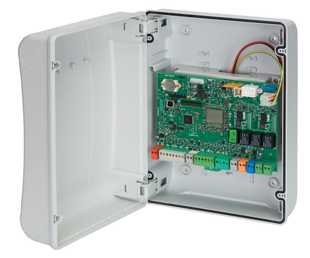
5 1. LAY-OUT OF ELECTRICAL BOX Te box contains te E124 control unit and te devices to power it. It must tereore be andled wit care during all installation stages, to avoid damaging its components. Te dimensions o te box are sown in Fig. 1: Fig. 2 sows te our 5 mm diam. oles or securing te box (re.a) to te wall, te tree ittings or installing te cable grippers M16/M20/ M25 (re. b) and te two lid inges (re. c). I it is necessary to remove and re-position te E124 control board, make sure tat te spacers (re.d) are itted in te supports Dimensions in mm Fig. 1 c a d c b Fig. 2 3


6 Te lid inges can be moved upward to allow opening te box ousing (Fig. 3): tey can also be removed and re-positioned in order to enable te lid to open to te rigt or let. Fig. 3 Wen you ave secured te box in te selected position, cover te securing oles (Fig. 2 re. a) and te screws wit te supplied plugs as sown in Fig. 4. Fig. 4 Connect te power cable to te switcing eeder as sown in Fig.5, making sure tat tere is an adequate termal breaker upstream. Ten plug te connector o te transormer to connector J1 on te board as indicated in ig.6. Neutral Line Eart Fig. 6 Fig. 5 4
7 2. LAYOUT AND COMPONENTS OF E124 BOARD M1A J14 J2 J13 J15 M1A DL14 LCD SW1 SW2 DL15 DL16 J1 DL19 DL20 SW7 SW3 DL17 DL18 SW4 SW5 SW6 DL12 DL13 DL1 DL2 DL3 DL4 DL5 J5 DL6 DL7 DL8 DL9 DL10 DL11 J8 J9 J10 J11 J12 J3 J4 J6 J Description o components LCD SIGNALS AND PROGRAMMING DISPLAY DL16 LED FOR SW1 PUSH-BUTTON (R1 PUSH-BUTTON) SW1 SW2 SW3 SW4 SW5 SW6 SW7 DL1 DL2 DL3 DL4 DL5 R1 PROGRAMMING PUSH-BUTTON R2 PROGRAMMING PUSH-BUTTON SETUP PUSH-BUTTON PROGRAMMING PUSH-BUTTON - PROGRAMMING PUSH-BUTTON F PROGRAMMING PUSH-BUTTON RESET SW SOFTWARE RESET PUSH-BUTTON INPUT STATUS CONTROL LED IN1 INPUT STATUS CONTROL LED IN2 INPUT STATUS CONTROL LED IN3 INPUT STATUS CONTROL LED IN4 INPUT STATUS CONTROL LED IN5 DL17 DL18 DL19 DL20 J1 J2 J3 J4 J5 J6 J7 LED FOR SW2 PUSH-BUTTON (R2 PUSH-BUTTON) LED FOR SW3 PUSH-BUTTON (SETUP PUSH-BUTTON) PRESSURE SIGNALLING LED RESET SW PUSH-BUTTON ALARM SIGNALLING LED ALARM POWER FEEDER SWITCHING CONNECTOR SECONDARY POWER SELECTOR CONNECTOR FOR CONNECTION TO BUS-2EASY DEVICES CONNECTOR FOR TERMINAL BOARD INPUTS CONNECTOR FOR OUT2 OUTPUT (see 2nd level prog.) TRAVEL LIMITS CONNECTOR CONNECTOR FOR LEAF 1 AND LEAF 2 ENCODER INPUTS DL6 INPUT STATUS CONTROL LED FCA1 J8 CONNECTOR FOR OUT1 OUTPUT (see 2nd level prog.) DL7 DL8 INPUT STATUS CONTROL LED FCC1 INPUT STATUS CONTROL LED FCA2 J9 J10 FLASHING LAMP OUTPUT CONNECTOR CONNECTOR FOR ELECTRICAL LOCK OUTPUT DL9 INPUT STATUS CONTROL LED FCC2 J11 LEAF 1 MOTOR CONNECTOR DL10 DL11 DL12 DL13 DL14 DL15 INPUT STATUS CONTROL LED ENC1 (Gatecoder) INPUT STATUS CONTROL LED ENC2 (Gatecoder) LED FOR DEVICE BUS-2EASY ACTIVE LED FOR BUS 2-EASY DIAGNOSTICS LED SIGNALLING PRIMARY POWER ON LED SIGNALLING SECONDARY POWER ON J12 J13 J14 J15 M1A LEAF 2 MOTOR CONNECTOR CONNECTOR FOR RECEIVER MODULE XF433/XF868 CONNECTOR: DECODER / MINIDEC / RP RECEIVER USB CONNECTOR FOR PROGRAMMING FROM PC ACCESSORIES MODULE CONNECTOR 5

8 2.2. Tecnical speciications 2.3. Inputs deault setting terminal board Primary power eed rom mains Secondary power eed Power absorbed rom mains Max. load or motor Power eed or accessories Accessories max. current Battery carge current Operating ambient tempeature Protective uses or unit Protective uses or power pack Function logics Work time Pause time Motor power Motor speed Connector inputs Terminal board inputs Terminal board outputs Programming wit switcing power eed 230/115 V~ - 50/60 Hz 24 Vdc - 16 A max. (min. 20 Vdc. - max. 28 Vdc.) stand-by = 4W max. ~ 400 W 7 A 24 Vdc 24Vdc max. 500 ma BUS-2EASY max. 500 ma 180 ma (-20-55) C All sel resetting 2.5 A Semiautomatic, Automatic, step-by-step Semiautomatic, Automatic wit reverse during pause, Automatic step-by-step, Saety devices automatic, Saety devices step-by-step automatic, b Semiautomatic, mixed logic bc, Dead-man, Automatic wit timer unction Programmable (rom 0 to 9 min 50 sec) Programmable (rom 0 to 9 min 50 sec) Programmable on 50 levels Programmable on 10 levels Switcing eeder, Battery, Decoder/Minidec/RP, X-COM, module XF433/868, USB BUS-2EASY, Inputs rom IN1 to IN5, Travel limit device, Encoder. Flasing lamp, Motors, Electrical lock, OUT1, OUT2 (programmable), power eed to accessories 1st and 2nd lev. wit 3 keys (, -, F) and LCD display. 3rd lev. wit PC connected via USB Terminal-board J4 IN1 OPEN A N.O. contact IN2 OPEN B N.O. contact IN3 STOP N.C. contact IN4 FSW OP N.C. contact IN5 FSW CL N.C. contact Connector J13 XF Module (OMNIDEC) Cannel 1 Cannel 2 Connector J14 - Radio Cannel 1 RP Cannel 2 RP2 OPEN A OPEN B OPEN A OPEN B 3. TERMINAL BOARDS, CONNECTORS, INPUTS AND SIGNALS 3.1. Power eed 115 V ~ 230 V ~ Fig. 7 J1: Select te correct power eed, by turning te power switcing selector to its correct position (Deault 230 Vac.) To ensure correct operation, te switcing eeder must be connected to te eart conductor in te system. Install an adequate dierential termal breaker upstream o te system. To access PROGRAMMING FROM PC, connect te USB cable to te dedicated connector and consult te relative instructions Secondary power eed J2: In te absence o a primary eed rom te mains, te control unit can be ed by a secondary low voltage (24Vdc) power eed. Power can be supplied by a pack o batteries, recarged by a battery carger integrated in te board, or by a stabilised power eeder. In bot cases, te power supply must ave te ollowing caracteristics: Voltage: (24 ± 4) Vdc Current: 16 A max. I you use an external stabilised eeder, you must disable te battery carger unction via te PC (see dedicated instructions). 6
9 3.3. Terminal board J3 BUS-2EASY accessories Terminal or connection o BUS-2EASY accessories. see par. 4.2, 4.3, Terminal board J4 SIGNALS INPUTS Connection o 2 N.O. contacts in parallel IN4 - Opening saety-devices contact (N.C. - terminal 5): see paragrap 4.1. To install several opening saety devices, connect te N.C. contacts in series. Oter more detailed programming possibilities are easible by programming wit a PC (see dedicated instructions). I opening saety devices are not connected, jumper connect terminals IN4 and GND, i te FAIL-SAFE saety device is not active, oterwise jumper connect IN4 and OUT1. Fig. 8 IN1 - OPEN A - Opening Command (N.O. - terminal 1): tis reers to any pulse generator (e.g.: pus-button) wic, by closing a contact, commands TOTAL OPENING. To install several total opening pulse generators, connect te N.O. contacts in parallel IN5 - Closing saety-devices contact (N.C. -. terminal 7): see paragrap 4.1. To install several closing saety devices, connect te N.C. contacts in series Oter more detailed programming possibilities are easible by programming wit a PC (see dedicated instructions). Oter more detailed programming possibilities are easible by programming wit a PC (see dedicated instructions). IN2 - OPEN B - Partial Opening command (N.O. - terminal 3): tis reers to any pulse generator (e.g.: pus-button) wic, by closing a contact, commands PARTIAL OPENING. For single lea systems, OPEN B commands an opening o lea 1 (motor 1) corresponding to 50% o total opening To install several partial opening pulse generators, connect te N.O. contacts in parallel Oter more detailed programming possibilities are easible by programming wit a PC (see dedicated instructions). I you select one o te ollowing logics (b, bc, C) input IN2 automatically becomes CLOSE (N.O). Connection o 2 NC contacts in series Fig. 9 IN3 - STOP contact command (N.C. - terminal 4): tis reers to any device (e.g.: pus-button ) wic, by opening a contact, can stop te motion o te automated system. To install several STOP devices, connect te N.C. contacts in series. Oter more detailed programming possibilities are easible by programming wit a PC (see dedicated instructions). I stop saety devices are not connected, jumper connect te STOP and GND terminals. I closing saety devices are not connected, jumper connect terminals IN5 and GND, i te FAIL-SAFE saety device is not active, oterwise jumper connect IN5 and OUT1. GND - (terminals 2-6): Negative or powering accessories 24 - (terminal 8): Positive to power eed accessories Te max. load o te accessories is 500mA, subdivided among terminal boards J4 and J7. To calculate maximum absorption, reer to te instructions or individual accessories Terminal boards J5, J8 OUT1 AND OUT2 Te two outputs can be set in one o te unctions described in 2nd level programming (see par.7.2.). Te deault value is: OUT1 = OUT2 = ALWAYS ACTIVE INDICATOR LIGHT. Maximum load applicable on every output: 24 Vdc wit 100 ma Terminal board J6 Opening and closing travel limit device Terminal board or connection o te opening (FCA1 and FCA2) and closing (FCC1 and FCC2) travel limit device. Te travel limit contacts FCC1, FCA1, FCC2 and FCA2 are all NC contacts. See 2nd level programming or te various conigurations applicable to te travel limit inputs. I tey are not used, do not jumper connect te contacts o te limit switces FCC1, FCA1, FCC2, FCA2 7

10 3.7. Terminal boards J7 - ENCODERS Encoders wit an open collector signal reerred to eart (e.g. Gatecoder) can be connected to detect te lea s angular position. For connections, see ig. 10. Te coniguration indicated in te drawing is te maximum one. Only 1 Gatecoder can be used. In tis case, te unused inputs do not ave to be jumper connected to eart WHITE WHITE RED BLACK RED BLACK 3.8. Terminal board J9 FLASHING LAMP Output or 24Vdc lasing lamp Maximum applicable load: 24 Vdc - 15 W Fig Led operation LED DL1 DL2 DL3 DL4 DL5 DL6 DL7 DL8 DL9 DL10 DL11 DL12 Description IN1 OPEN A IN2 OPEN B IN3 STOP IN4 FSW OP IN5 - FSW CL FCA1 FCC1 FCA2 FCC2 ENC1 ENC2 ON (contact closed) Command enabled Command enabled OFF (contact open) Command disabled Command disabled Command disabled Command enabled Saety devices disabled Saety devices tripped Saety devices disabled Saety devices tripped Opening travel-limit Opening travel-limit devices ree devices engaged Closing travel-limit Closing travel-limit devices ree devices engaged Opening travel-limit Opening travel-limit devices ree devices engaged Closing travel-limit Closing travel-limit devices ree devices engaged Flasing during operation (Gatecoder) Flasing during operation (Gatecoder) SIGNALLING LED FOR DEVICE BUS-2EASY ACTIVE 3.9. Terminal board J10 ELECTRIC LOCK Output or 12V ac or 24V dc electric lock Motors terminal block J11 (MOT1): Connection o motor connected to lea 1, i.e. te lea wic opens irst during an opening operation. J12 (MOT2): Connection o te motor connected to lea 2, i.e. te lea wic opens second. I only one motor is connected, it must be connected to terminal J11 (MOT1). DL13 DL14 DL15 DL16 DL17 DL18 DL19 DL20 SIGNALLING LED FOR BUS 2-EASY DIAGNOSTICS LED SIGNALLING PRIMARY POWER ON LED SIGNALLING SECONDARY POWER ON LED FOR SW1 PUSH-BUTTON (R1 PUSH-BUTTON) LED FOR SW2 PUSH-BUTTON (R2 PUSH-BUTTON) LED FOR SW3 PUSH-BUTTON (SETUP PUSH-BUTTON) LED RESET SW PUSH-BUTTON ALARM SIGNALLING LED ALARM I, during te irst movement o te SETUP procedure, te leaves close instead o opening, te motor connection cables must be canged over Connector J13 XF MODULE rapid connection Te control unit as an integrated 2-cannel decoding system (DS, SLH, LC/RC) named OMNIDEC. Tis system makes it possible to save troug an extra receiver module XF433 or XF868 radio commands o te same requency, but o a dierent type (DS, SLH, LC/RC). It is possible to save bot total opening (OPEN A) and partial opening (OPEN B) o te automated system, up to a maximum o 256 cannels. Flasing LED ALARM indicates alarm in progress (a situation wic does not prejudice gate operation) LED ALARM on steady ligt indicates error in progress (a situation wic blocks operation until cause o error is eliminated) Oter more detailed programming possibilities are easible by programming wit a PC (see dedicated instructions). Fig. 11 Insert and remove te boards only ater cutting power. 8
11 3.13. Connector J14- connection o MINIDEC, DECODER AND RP It is used or rapid connection o Minidecs, Decoders and RP/RP2 Receivers. I you are using an RP2 twin-cannel receiver, you will be able to directly command two dierent radio cannels, OPEN A and OPEN B o te automated system rom a twin-cannel radio control. I using a single-cannel Minidec, Decoder or RP, you can command only one radio cannel, OPEN A. An example o a radio accessory connection Fit te accessory wit te components side directed toward te board interior. J14 E124 Fig. 12 Insert and remove te boards only ater cutting power. Oter more detailed programming possibilities are easible by programming wit a PC (see dedicated instructions). 4. ELECTRICAL CONNECTIONS OPEN B OPEN A STOP Enable in 2nd level programming 24Vdc * BUS 24Vdc 3W * LOCK 12Vac 24Vdc M1 M2 Use wit motors witout a BUS2EASY encoder Connection o traditional saety devices and potocells * LAMP 24Vdc 24Vdc 24Vdc 15W 3W Max load 24Vdc - 500mA Fig. 13 Wit te E124 control unit, you can use bot traditional potocells (N.C. contact wit relay) and/or potocells wit BUS-2EASY (open collector contact). Te positioning o te potocells and teir operation is scematised in Fig. 14. Opening /closing saety devices 4.1. Connection o traditional saety devices Beore you connect te potocells we advise you to select te type o operation according to te movement zone tey ave to protect: Closing saety devices: tey are tripped only during te automated system closing movement, and, tereore, are suitable or protecting te closure zone against te risk o impact. Fig. 14 Opening saety devices: tey are tripped only during te automated system opening movement, and, tereore, are suitable or protecting te opening zone against te risk o impact. Opening /closing saety devices: tey are tripped during te automated system opening and closing movement, and, tereore, are suitable or protecting te entire movement zone against te risk o impact. Closing saety devices Opening saety devices 9
12 Connection o no saety and stop device Connection o 2 pairs o potocells J4 Connection o 1 pair o closure potocells wit FAIL-SAFE activated Set o1 = 01 in te second programming level J4 Fig. 15 Oter saety devices RX CL1 TX CL2 TX CL1 RX CL2 Connection o 1 pair o opening potocells Fig. 18 OUT1 Oter saety devices RX CL TX CL OUT1 OUT1 J4 Oter saety devices Connection o 1 pair o closure potocells wit FAIL-SAFE and STOP de-activated RX OP TX OP Fig. 19 Connection o one closing saety device and one opening saety device Oter saety devices RX CL TX CL J4 Fig. 16 Connection o a pair o closing potocells and a pair o opening/closing potocells wit disabled FAIL-SAFE saety device and STOP Fig. 20 I you do not use te FAILS-SAFE device, you must connect te transmitters power eed to terminals 6 and 8 o J4. I you use te FAIL-SAFE device, connect te transmitters power eed to OUT1 ater you ave set it appropriately (see 2nd level programming and ig. 16). RX CL TX CL I you use te FAIL-SAFE device, te non-used saety inputs too must be jumper connected to te OUT1 negative (see Fig.16). TX OP/CL RX OP/CL Fig
13 Connection o a pair o closing potocells, a pair o opening potocells and a pair o opening/closing potocells RX CL TX OP/CL RX OP J4 TX CL RX OP/CL TX OP Fig Potocells BUS-2EASY Tis board is supplied wit a BUS-2EASY circuit enabling easy connection o a ig number o BUS-2EASY saety auxiliary devices (e.g. up to 16 potocells pairs), appropriately programmed, using only two cables witout polarity. Beore connecting te potocells, we advise you to select te type o operation (Fig.23) according to te movement zone tey must protect and position bot on te transmitter and receiver - te dip-switces as sown in Tab.1: Closing potocells: tey are tripped only during te automated system closing movement, and, tereore, are suitable or protecting te closure zone against te risk o impact. I you ave to connect two or more BUS-2EASY closing potocells, coose dierent addresses or eac pair used. Opening potocells: tey are tripped only during te automated system opening movement, and, tereore, are suitable or protecting te opening zone against te risk o impact. I you ave to connect two or more BUS-2EASY opening potocells, coose dierent addresses or eac pair used. Connection o a pair o opening and a pair o closing potocells RX OP TX OP J4 Opening /Closing potocells: tey are tripped during te automated system opening and closing movement, and, tereore, are suitable or protecting te entire movement zone against te risk o impact. I you ave to connect two or more BUS-2EASY closing potocells, coose dierent codes or eac pair used. Pulse generators: used as pulse generators to open te automated system. TX CL RX CL Fig. 22 A maximum o 16 pairs o BUS-2EASY potocells can be connected to te board. Te potocells are split into groups: Opening potocells: max 6 Closing potocells: max 7 Opening /Closing potocells: max 2 Potocell used as an OPEN pulse: max 1 Fig. 23 Fig. 24 sows a 2-swing lea automated system indicating te coverage beams o te potocells: A: Potocells wit OPENING and CLOSING action B: Potocells wit OPENING action C: Potocells wit OPENING action D: Potocells wit CLOSING action 11
14 RX - TX Addressing te BUS-2EASY potocells Important: te same address must be given to bot transmitter and receiver (te same DIP-SWITCH setting) Make sure tat tere are not two or more potocell pairs wit te same address. (te same DIP-SWITCH setting) I you are not using any BUS-2EASY accessory, leave ree connector BUS-2EASY (J3- ig. 7). Te ollowing table sows te programming operations o te dip-switc inside te transmitter and te BUS 2-EASY potocells receiver. RX DL2 DL1 ON DS1 BUS BUS TX ON DS1 DL2 BUS BUS Dip1 Dip2 Dip3 Dip4 Ri. Type OFF OFF OFF OFF OFF OFF OFF ON OFF OFF ON OFF OFF OFF ON ON OFF ON ON OFF OFF ON ON ON ON OFF OFF OFF ON OFF OFF ON ON OFF ON OFF B - C DL1 = Alignment DL2 = BUS-2EASY/ power supply status DS1 = Programming dip-switces 2EASY OPENING 4.3. Addressing te BUS-2EASY encoders Connection o te BUS-2EASY input in te control board is via te bipolar cables wic come out o te encoders. Unlike te case o te potocell devices, te polarity o te BUS-2EASY line connection determines weter te encoder belongs to one lea rater tan to te oter. Tis is wy you must pay great attention to te indications o te status LEDs on te body o eac encoder (Fig ). Below we list te unctions o LEDs DL1, DL2, and DL3, and teir statuses: Encoder connection and LED status LED ON FLASHING OFF DL 1 Power ON and BUS -2EASY communicating wit board Power ON but BUS- 2EASY not communicating No power to or communication wit BUS-2EASY DL 2 DL 3 Lea 1 encoder / Lea 2 encoder Lea not moving Pulses read wile lea moving Lea not moving DL 1 must always be ligted to guarantee correct connection between encoder and board. DL 2 determines te lea on wic te encoder is installed. Providing te coniguration is correct, te automated system will sow: an encoder wit DL2 ligted in lea 1, and an encoder wit DL2 OFF in lea 2. I tere is an incorrect connection, i.e. indicating two encoders wit te same status o te DL2 LEDs, during te learning procedure o te BUS-2EASY accessories, te DL 1 LEDS o bot encoders sow a FLASHING status. In tis situation, reer to te coniguration in TAB.4 to deine wic encoder connection to rotate. DL 3 indicates, on a steady lasing beam, te reading o te pulses wile te lea is moving. Wen te lea is motionless, DL 3 can be eiter ligted or OFF. ON OFF ON ON ON ON OFF OFF ON ON OFF ON ON ON ON OFF OFF ON OFF OFF OFF ON OFF ON D A CLOSING OPENING and CLOSING ON ON ON ON / OPEN PULSE Oter more detailed programming possibilities are easible by programming wit a PC (see dedicated instructions). 12


15 Encoder wiring or operator S700H/S800H DL1 ON LEAF 1* TWO LEDs ON LEAF 2 ONE LED ON DL2 OFF DL3 OFF DL3 OFF DL2 ON Lea 1 Lea 2 DL1 ON DL1 ON LEAF 2 ONE LED ON LEAF 1* TWO LEDs ON DL2 ON DL3 OFF DL3 OFF DL2 OFF * Lea 1 opens as irst and closes as second. I no rebate is present between lea 1 and 2, set lea delay to zero on te control board. Lea 2 Lea 1 DL1 ON Reverse te encoder wires to excange between te encoder associated wit lea 1 and te encoder associated wit lea 2 and vice versa Fig SAFECODER wiring (Operators 412, 413, 415, 770N, S450H) LEAF 1* LEAF 2 DL 1 DL 2 DL 3 MAKE SURE THAT LEDs DL1 AND DL2 ARE LIGHTED ON LEAF 1, WHEN THE MOTOR IS AT REST MAKE SURE THAT LED DL1 IS LIGHTED ON LEAF 2, WHEN THE MOTOR IS AT REST DL 1 DL 2 DL 3 LEAF 1 TWO LEDs ON LEAF 2 ONE LED ON LEAF 2 LEAF 1* DL 1 DL 2 DL 3 MAKE SURE THAT LED DL1 IS LIGHTED ON LEAF 2, WHEN THE MOTOR IS AT REST MAKE SURE THAT LEDs DL1 AND DL2 ARE LIGHTED ON LEAF 1, WHEN THE MOTOR IS AT REST DL 1 DL 2 DL 3 LEAF 2 ONE LED ON LEAF 1 TWO LEDs ON Fig. 25 ENCODER WIRES REVERSING OPERATION Fig. 26 * Lea 1 opens as irst and closes as second. I tere is no rebate between lea 1 and 2, set te lea delay to zero on te control board. ENCODER LEAF 1 ENCODER LEAF 2 Reverse te encoder wires to excange between te encoder associated wit lea 1 and te encoder associated wit lea 2, and vice versa 13
16 5. PROGRAMMING Programming is divided in two levels: BASIC programming ADVANCED programming Te programming pases are (see Tab.): 1. to access PROGRAMMING (1A or 1B); 2. to sow te set values and modiy tem, i you want. Canging te values is eective immediately, wile te inal memorisation must be carried out upon exiting programming (St). 3. exit te programming by using St unction. Select Y to SAVE te coniguration you just perormed, oterwise select no to EXIT WITHOUT SAVING any canges. You can EXIT programming at anytime: press and old F and ten also - to switc directly to St. -/R2 Tis board also allows programming using a PC or MAC. Tis programming requires connection to PC/MAC via USB cable and USB-B relevant port. Te programming SOFTWARE wit relevant instructions, must be downloaded rom te website: F Te programming using a PC/MAC, wit te deault PASSWORD does not inibit te programming by board. Te writing PC will be displayed in correspondence wit te modiied values. Notes: wen you modiy te values by board te previous PC/MAC programming will be overwrote. Te deault password is Te programming using a PC/MAC, wit a modiied PASSWORD (dierent rom te deault one), will inibit te programming by board. I one o te buttons is pressed, te display will sow PC programming or 5 sec and canges will be allowed only by PC /MAC. basic programming F A B C 1A. press and old F : te irst unction appears ë 1 release F: te unction value is displayed F using or -, scroll te available values until te te desired one press F: to move to te next unction ë 1 unction St (last basic or advanced unction) advanced programming 1B. press and old F and ten also : te irst unction appears ë 1 /R1 F release te keys: te unction value is displayed /R1 F /R1 -/R2 F select Y to save te programming oterwise select no to exit te programming witout saving Tab. Programming pases. ë 1 te unction is displayed until you old 14
17 5.1. Basic programming Display Basic Function Deault 0 Deault 1 Deault 2 Deault 3 Deault 4 Deault 5 cf Conigures te parameters wit DEFAULT values corresponding to an installation wit non-faac operators. (see deault column 0). 1 Conigures te parameters wit DEFAULT values corresponding to an installation wit operators FAAC 412, 413/415, 770, 390, 770N (see deault column 1). 2 Conigures te parameters wit DEFAULT values corresponding to an installation wit operators FAAC 391 (see deault column 2). 3 Conigures te parameters wit DEFAULT values corresponding to an installation wit operators FAAC S700H/ S800H (see deault column 3. 4 Conigures te parameters wit DEFAULT values corresponding to an installation wit operators FAAC 418. (see column deault 4). 5 Conigures te parameters wit DEFAULT values corresponding to an installation wit operators FAAC S450H (see column deault 5). PC Mixed coniguration rom a PC/MAC df DEFAULT: Y no At te time o canging te set motor type on te board, te relevant deaults are uploaded. indicates tat all te set values correspond to te deault values. indicates tat one or more set values are dierent rom te deault. Y Y Y Y Y Y LO Set Y i you want to restore te deault settings. FUNCTION LOGICS: E EP S SA SP Semi-automatic Semi-automatic Step-by-Step Automatic Saety Devices Automatic wit reversal during pause Automatic Step-by-Step Saety Devices A1 Automatic 1 A AP At b bc C CU Automatic Automatic Step-by-Step Automatic timer Semi-automatic b Mixed (Pulses or opening / Dead-man commands or closing) Dead-man Logic modiied rom a PC/MAC Oter more detailed programming possibilities are easible by programming wit a PC (see dedicated instructions). E E E E E E 15
18 Display Basic Function Deault 0 Deault 1 Deault 2 Deault 3 Deault 4 Deault 5 PAUSE TIME A (visualised only i te selected logic allows PA automatic reclosing): Pause time ollowing a TOTAL opening command. It as only eect i a logic wit pause time was selected. Can be adjusted rom 0 to 59 sec. in one-second steps. Next, te viewing canges in minutes and ten seconds (separated by a dot) and time is adjusted in 10-second steps, up to te maximum value o 9.5 minutes. Pb Mn E.g.: i te display sows 2.5, te pause time will be 2 min. and 50 sec. PAUSE TIME B (visualised only i te selected logic allows automatic reclosing): Pause time ollowing a PARTIAL opening command. It as only eect i a logic wit pause time was selected. NR. OF MOTORS: You can select te number o motors present in te system: 1 = 1 motor 2 = 2 motors I te SETUP is perormed wit only one motor, and later two motors are used, te board will signal error 14 - coniguration error, wic can be deleted by repeating te SETUP wit two motors or by returning to one motor. I a SETUP is perormed wit two motors and later only one is used, te board will not signal an error. Only te motor connected to input M1 will move. Wen programming rom a PC/MAC, you can select dierent partial openings. F1 MOTOR 1 POWER : You can adjust te maximum power o motor 1, wic is te same during bot opening and closing. 01 = minimum power 50 = maximum power I te power is modiied, we recommend perorming a new SETUP - see te related paragrap. F2 Oter more detailed programming possibilities are easible by programming wit a PC (see dedicated instructions). MOTOR 2 POWER (visualised only wit te unction Mn = 2): You can adjust te maximum power o motor 2, wic is te same during bot opening and closing SP SPEED: Adjusts te motion speed o te motors. Tere are 10 levels. Te value is relative and not absolute, because te speed value reers to te weigt o te lea measured during te SETUP cycle = minimum speed 10 = maximum speed Oter more detailed programming possibilities are easible by programming wit a PC (see dedicated instructions). 16
19 Display Basic Function Deault 0 Deault 1 Deault 2 Deault 3 Deault 4 Deault 5 ENCODER USE: En no no no Y no Y FA FC Cd You can enable/disable te use o encoders (bot BUS and GATECODER encoders): Y no = encoders on bot motors = encoders disabled Wen using conigurations 3 or 5 it is mandatory to use te encoder, no is not selectable LIMIT SWITCH WHEN OPENING: Lets you set or disable use o te opening limit switc on swingleaves. no = opening limit switces disabled 01 = te limit switc determines te stopping o motion 02 = te limit switc determines te start o deceleration Ater aving canged te value o tis unction, SETUP is required: te card will signal error 14 (coniguration error) until te SETUP is perormed again or until te previous value is restored LIMIT SWITCH WHEN CLOSING: Lets you set or disable use o te closing limit switc on swingleaves. no = closing limit switces disabled 01 = te limit switc determines te stopping o motion 02 = te limit switc determines te start o deceleration Ater aving canged te value o tis unction, SETUP is required: te card will signal error 14 (coniguration error) until te SETUP is perormed again or until te previous value is restored. DELAY FOR CLOSING LEAF (visualised only wit te unction Mn = 2): Is te delay time or starting lea 1 closing wit respect to lea 2. Makes it possible to avoid overlapping o te two leaves. Adjustable rom 00 to 59 sec, in 1- second steps. Next te value 59, te viewing canges to minutes and tents o a second (separated by a decimal point) and time is adjusted in 10-second steps up to te maximum value o 3 minutes. no no no no no no no no no no no no bu M2 e.g.: i te display sows 1.2, te time is 1 min and 20 sec BUS-2EASY DEVICES ENTRY: See te related paragrap. MOTOR 2 dead-man DRIVE mode (visualised only wit te unction Mn = 2) /R1 OPENS (visualising op) until te button is eld down no no no no no no /R2 CLOSES (visualising cl) until te button is eld down 17
20 Display Basic Function Deault 0 Deault 1 Deault 2 Deault 3 Deault 4 Deault 5 M MOTOR 1 dead-man DRIVE mode /R1 OPENS (visualising op) until te button is eld down -/R2 CLOSES (visualising cl) until te button is eld down tl WORK TIME LEARNING (SETUP): See te related paragrap. St AUTOMATED SYSTEM STATUS: You can exit programming, coosing weter or not to save te coniguration you just perormed. 1. set te coice: Y no to SAVE and EXIT te programming to EXIT te programming WITHOUT SAVING Y 2. press te button F to conirm; at te end te display returns to visualize te automated system status: 00 = CLOSED 01 = OPEN 02 = Stationary ten OPENS 03 = Stationary ten CLOSES 04 = In PAUSE 05 = during Opening 06 = during Closing 07 = FAIL SAFE in progress 08 = cecking BUS-2EASY devices in progress 09 = Pre-las ten OPENS 10 = Pre-las ten CLOSES 11 = Emergency open 12 = Emergency close HP = Hold position WARNING I power is lost to te board prior to conirmation (step 2.), all canges made will be lost. You can EXIT programming at any time: press and old F and ten also - to switc directly to St. -/R2 F 18
21 5.2. Advanced programming Display bo cs rs Advanced Function TIME OF MAXIMUM POWER AT STARTING: You can set te starting time. During start te motors work at maximum power or starting te movement. Adjustable rom 00 to 10 sec, in 1-second steps (ignoring te power level selected wit F1 and F2). Oter more detailed programming possibilities are easible by programming wit a PC (see dedicated instructions). FINAL STROKE WHEN CLOSING (RAM STROKE) (NOT displayed i unction FC = 1): Lets you enable/disable te ram stroke on swing-leaves. Te ram stroke acilitates latcing o te electric lock by activating te motors at maximum power during inal closing. Y no = enabled (or 2 sec) = disabled In case o systems wit an absolute encoder, to enable tis unction a setup must be perormed using te automatic lea stop on te mecanical contact point. REVERSE STROKE WHEN OPENING displayed i unction FA = 1): Lets you enable/disable te reverse stroke on lea doors. Te reverse stroke acilitates unlatcing o te electric lock. Wen te automatic system is closed, beore starting to open, te motors give a brie pus to close. Deault 0 Deault 1 Deault 2 Deault 3 Deault 4 Deault no no no no no no no no no no no no EL Od Y no = enabled (or 2 sec) = disabled In case o systems wit an absolute encoder, to enable tis unction a setup must be perormed using te automatic lea stop on te mecanical contact point. ELECTRIC LOCK ON LEAF 2: Te board as a terminal dedicated to te connection o an electric lock. Normally te electric lock must be connected to lea 1. I te electric lock is located on lea 2, adjust te parameter. Tis parameter does not allow te setting Y i Mn = 2) Y = electric lock on lea 2 no = electric lock on lea 1 DELAY FOR OPENING LEAF (visualised only wit te unction Mn = 2): You can set te delay time or starting lea 2 opening wit respect to lea 1, in order to avoid overlapping o te two leaves. Adjustable rom 00 to 59 sec, in 1- second steps. Next te value 59, te viewing canges to minutes and tents o a second (separated by a decimal point) and time is adjusted in 10-second steps up to te maximum value o 1.3 minutes. e.g.: i te display sows 1.2, te time is 1 min and 20 sec. no no no no no no
22 Display r1 r2 PF P Ad EC US Advanced Function LEAF 1 DECELERATION: You can adjust te deceleration space as a percentage o te total travel o lea 1. Adjustable rom 00 to 99 %, in 1% steps. 00 = no deceleration 01 = minimum deceleration space 99 = maximum deceleration space LEAF 2 DECELERATION (visualised only wit te unction Mn = 2): You can adjust te deceleration space as a percentage o te total travel o lea 2. Adjustable rom 00 to 99 %, in 1% steps. 00 = no deceleration 01 = minimum deceleration space 99 = maximum deceleration space PRE-FLASHING: You can enable/disable te pre-lasing. Pre-lasing duration = 3 sec. You can coose: no OC CL OP PA = disabled = pre-lasing beore eac movement = pre-lasing beore a closing movement = pre-lasing beore an opening movement = pre-lasing only at te end o te pause time CLOSING PHOTOCELLS: Te intervention o closing potocells causes te reversing o automated system (opening). You can coose: Y no = operate te reversal only ater te potocells are released = operate te reversal immediately ADMAP FUNCTION: Allows operation in compliance wit Frenc regulation NFP 25/362. Y no = enabled = disabled ANTI-CRUSHING SENSITIVITY: Varying tis unction varies te amount o time ater wic, in case o obstacle, te board commands reversal o te leaves, or it will command a stop i te leaves are in te contact point searc space (see te parameter rb). Te ourt consecutive obstacle detected in te same direction and position will be deined as a contact point and te lea will stop in tat position. 01 = minimum sensitivity (maximum time beore reversal) 10 = maximum sensitivity (minimum time beore reversal) ULTRA-SENSITIVITY: Tis unction activates an obstacle detection system, based on te control o te variation o te current absorbed by te motor, causing immediate lea reversal. Deault 0 Deault 1 Deault 2 Deault 3 Deault 4 Deault no no no no no no no no no no no no no no no no no no no no no Y no Y Y = active no = excluded 20
23 Display rb Advanced Function MECHANICAL STOP SEARCH ANGLE (NOT displayed i unction FC or FA = 01): You can adjust te contact point searc angle witin wic te board will stop movement witout reversing, i it encounters an obstacle or te contact point. Deault 0 Deault 1 Deault 2 Deault 3 Deault 4 Deault Adjustable rom 0.3 to 20 degrees. From 0.3 to 9.9 degrees, adjustments are made in 0.1 degree steps. From 10 to 20 degrees, adjustments are made in 1 degree steps. SF SOFT TOUCH: (visualised only wit te unction En = no): Ater toucing te travel stop point, te leaves reverse and ten rest gently. Y = active no = excluded Tis unction can be useul to respect te impact curve speciied by current standards. no no no no no no o1 OUT 1: Oter more detailed programming possibilities are easible by PC programming (see dedicated instructions). You can set te output OUT1 (open collector N.O.) in one o te ollowing unctions: 00 = always active 0 1 = FAIL-SAFE 02 = INDICATOR LIGHT (o = closed; on = during opening and open/in pause; lasing = during closing) 03 = COURTESY LIGHT (stays on or te duration o te movement (even in SETUP) in addition to te set time o unction t1 04 = ACTIVE ERROR 05 = automated system OPEN or in PAUSE 06 = automated system CLOSED 07 = automated system MOVING 08 = automated system in EMERGENCY 09 = automated system in OPENING 10 = automated system in CLOSING 11 = electric lock control beore CLOSING 12 = saety device ACTIVE 13 = TRAFFIC LIGHT unction (active wen OPENING and wit automated system OPEN) 14 = timed output wic can be activated rom te second radio cannel OMNIDEC (see unction t1) 15 = output wic can be activated rom te second radio cannel OMNIDEC (step-by-step unction) 16 = active during movement o lea 1 17 = active during movement o lea 2 18 = Instrusion detection 19 = System working on battery I tr is displayed, it indicates tat te output is used as a TIMER set rom te PC/MAC sotware. 21
24 Display Advanced Function t1 OUT 1 TIMING (visualised only wit te unction o1 = 03 or o1 = 14): o2 You can adjust te timing o OUT 1 output i a timed unction as been selected wit a time rom 1 to 59 minutes in 1-minute steps or unctions OUT 2: You can set te output OUT2 (open collector N.O.). See te options as o1. Deault 0 Deault 1 Deault 2 Deault 3 Deault 4 Deault t2 AS OUT 2 TIMING (visualised only wit te unction o2 = 03 or o2 = 14): Adjustable as t1. MAINTENANCE REQUEST - CYCLE COUNTER (linked to te subsequent two unctions): You can enable te signaling o maintenance request, or te cycle counter. Y no enable te SIGNALING wen te programmed number o cycles as been reaced (as deined in subsequent two unctions nc and nd). Signaling consists o a pre-lasing o 8 sec (in addition to te time may already be set wit te unction PF) beore eac movement. enable te CYCLE COUNTER, tat will be displayed in te subsequent two unctions nc and nd up to a displayed maximum o 65, no no no no no no nc I te number o cycles perormed is greater tan 65,530 te subsequent two unctions nc and nd will display 65 and 53, respectively. CYCLE PROGRAMMING (THOUSANDS): I AS = Y te display will sow te number o tousands o cycles ater wic te signaling o maintenance request begins (can be set rom 0 to 99). I AS = no te display will sow te number o tousands o work cycles perormed. Te value displayed is updated wit te succession o te cycles, interacting wit te value in nd nd Wen AS = no you can reset te cycle counter: press simultaneously and - or 5 sec. CYCLE PROGRAMMING (TENS): I AS = Y te display will sow te number o tens o cycles ater wic te signaling o maintenace request begins (can be set rom 0 to 99). I AS = no te display will sow te number o tens o work cycles perormed. Te value displayed is updated wit te succession o te cycles, interacting wit te value in nc e.g.: i te system as perormed 11,218 cycles, nc = 11 and nd = 21 will be displayed 22

25 St AUTOMATED SYSTEM STATUS: You can exit programming, coosing weter or not to save te coniguration you just perormed. 1. set te coice: Y no to SAVE and EXIT te programming to EXIT te programming WITHOUT SAVING 2. press te button F to conirm; at te end te display returns to visualize te automated system status: Y 00 = CLOSED 01 = OPEN 02 = Stationary ten OPENS 03 = Stationary ten CLOSES 04 = In PAUSE 05 = Opening 06 = Closing 6. BUS 2EASY DEVICE INSTALLATION You can add BUS-2EASY devices to te system at any time, proceeding as ollows: 1. Cut o te electrical power to te board. 2. Install and set te BUS-2EASY accessories according to te instructions o te devices. 3. Connect te BUS-2EASY devices according to te instructions o Capter ELECTRICAL CONNECTIONS. 4. Power up te board. 5. Complete te procedure or BUS-2EASY device entry. 07 = FAIL SAFE in progress 08 = cecking BUS-2EASY devices in progress 09 = Pre-las ten OPENS 10 = Pre-las ten CLOSES 11 = Emergency open 12 = Emergency close HP = Hold position 6.1. BUS-2EASY device entry 1. Access BASIC programming and scroll troug te unctions up until bu. Wen F is released, te display will sow te BUS-2EASY devices status (see te igure). 2. Perorm te entry: simultaneously press and old and - or at least 5 sec (during tis time, te display will blink). 3. Y will appear as a conirmation o entry completion. 4. Release te and - buttons. Te status o te BUS-2EASY devices will be displayed. I no BUS device as ever been entered in te board, te display will read no. Opening potocells: ON = entered and engaged Encoder 1:ON = correctly connected and entered Opening potocells and Closing potocells: ON = entered and engaged BUS Status: always ON Encoder 2: ON = correctly connected and entered OPEN potocell: ON = entered and engaged Closing potocells: ON = entered and engaged Fig. Visualising te BUS-2EASY status in te unction bu: eac segment o te display sows one type o device. 23
26 Fig. examples o BUS-2EASY status visualization on display. In STAND BY (gate closed and in stand-by) wit BUS-2EASY Encoder on lea 1 and lea 2 and BUS-2EASY Potocells correctly connected and entered. In case o BUS-2EASY Encoder on lea1 and lea 2 and BUS-2EASY Potocells correctly connected and entered and wit closing potocells engaged: 6.2. Cecking te securing devices entered on te board To veriy te types o BUS device recognised troug te entry: 1. Press and old te button during stand-by visualisation; te segments corresponding to at least one entered device will go ON. E.g.: at least one pair o opening potocells correctly entered Encoder on lea 1 correctly entered /R1 at least one pair o closing potocells correctly entered Encoder on lea 2 correctly entered To ceck te condition o te BUS-2EASY connection, veriy te LED on te board: LED DL15 (Red) ON OFF Saety device engaged or pulse generator active NO saety device engaged neiter pulse generator active LED DL14 (Green) ON steady Slow blinking (blink every 2,5 sec) Rapid blinking (blink every 0.5 sec) OFF Normal activity (led ON even i tere are no devices). BUS-2EASY line sort-circuit. Error in te BUS-2EASY connection. Repeat te device entry. I te error occurs again, ceck: - Tat tere are no more tan one device in te system wit te same address. - Calling error (number > or < te connected BUS devices). - FAIL SAFE error on te BUS device. Board in Sleep mode (i used). 7. TIME LEARNING - SETUP Wen te board is powered, i a SETUP as never been perormed, or i te board requests it, on te display S0 indicates tat a SETUP must be perormed. During SETUP, te connected BUS-2EASY accessories are always entered. Te BUS-2EASY encoders entered by te SETUP must always be enabled using te parameter En (BASIC Programming). During SETUP all saety devices are disabled! Tereore, carry out te operation avoiding any transit in te lea movement area. I a system witout an encoder is installed, mecanical stops will be required or te leaves. 24
27 Perorm te SET-UP as ollows: 1. Enter BASIC programming and go to te parameter tl, wen F is released -- will appear. 2. Ensure tat te gate leaves are closed. Oterwise, proceed as ollows: - Press and old - to close lea 2 - Press and old to close lea 1 Sould pressing and/or - command opening o te corresponding lea, cut o power and, on terminal board J11 or J12, invert te cables o te corresponding motor. 3. Wit te gate leaves closed, launc SETUP by pressing and olding and - until S1 begins to las on te display (about 3 sec). 4. Release e -. Lea 1 begins its opening movement. Operation WITHOUT Saecoder Lea 1 automatically acknowledges te mecanical stop. 5. On te display S2 will las (only i 2 motors ave been selected): lea 2 begins opening. Operation WITHOUT Saecoder Lea 2 automatically acknowledges te mecanical stop. Operation WITH Saecoder Lea 1 automatically acknowledges te mecanical stop. It will in any case be possible to stop lea movement at any time and in te desired point by sending an OPEN A pulse. Operation WITH Saecoder Lea 2 automatically acknowledges te mecanical stop. It will in any case be possible to stop lea movement at any time and in te desired point by sending an OPEN A pulse. Steps 4 and 5 wit unction FA : FA = 01 (te limit switc determines te stopping o motion) wit Saecoder installed te OPEN A pulse or stopping motion is ignored. FA = 02 (te limit switc determines te start o deceleration) send an OPEN A pulse only ater involving te opening limit switc, witout Saecoder, make sure tat te limit switc is engaged beore te mecanical stop. 6. On te display S3 will las (only i 2 motors ave been selected): lea 2 begins closing. Operation WITHOUT Saecoder Lea 2 automatically acknowledges te mecanical stop. 7. On te display S4 lases: lea 1 begins closing. Operation WITHOUT Saecoder Lea 1 automatically acknowledges te mecanical stop Operation WITH Saecoder Lea 2 automatically acknowledges te mecanical stop. It will in any case be possible to stop lea movement at any time and in te desired point by sending an OPEN A pulse. Operation WITH Saecoder Lea 1 automatically acknowledges te mecanical stop. It will in any case be possible to stop lea movement at any time and in te desired point by sending an OPEN A pulse. Steps 6 and 7 wit unction FC : FC = 01 (te limit switc determines te stopping o motion) te OPEN A pulse or stopping motion is ignored. FC = 02 (te limit switc determines te start o deceleration) wit Saecoder installed send an OPEN A pulse only ater involving te closing limit switc, witout Saecoder, make sure tat te limit switc is engaged beore te mecanical stop 8. S5 lases on te display: bot leaves open at ull speed. 9. Te board will automatically exit te programming menu and will display te automated system status ( 00) to conirm tat te SETUP procedure as been completed correctly. I te procedure is not completed correctly, on te display S0 will start lasing, indicating tat a new SETUP procedure must be perormed. Te deceleration spaces can be conigured and modiied rom te display using te parameters r1 and r2 (see Advanced Programming) witout repeating te SETUP. 25
 and more radio controls aving dierent tecnology but te same requency.")

28 8. MEMORISING THE RADIO CODE Te control board eatures an integrated 2-cannel decoding system (DS, SLH/SLH LR, RC) called OMNIDEC. Tis system lets you memorise, using an additional receiver module (on J5 connector) and more radio controls aving dierent tecnology but te same requency. You can tus control bot total opening (OPEN A) and partial opening (OPEN B). Te dierent types o radio code (DS, SLH/SLH LR, LC/RC) can coexist simultaneously on te two cannels. You can enter up to 250 radio codes divided between OPEN A and OPEN B/CLOSE. To use dierent encoding systems on te same cannel, you must complete te learning o eac encoding system and ten repeat te procedure or te oter one. Oter, more detailed, programming options are available using a PC/MAC (see dedicated PC/MAC instructions). For example, you can set an automatic OPEN command on te radio cannel to command an automatic cycle (open-pause-close) regardless o te selected logic Memorising te SLH/SLH LR radio controls 1. Press and old (OPEN A programming) or - (OPEN B/CLOSE programming). 2. Ater keeping te button pressed or about 5 sec, te corresponding radio LED (DL11 or DL12) will begin to las slowly or about 20 sec. 3. Release te button. 4. Simultaneously press and old P1 and P2 on te SLH/SLH LR radio control (only MASTER radio control). 5. Te radio control LED will begin to las. 6. Release bot buttons. 7. Ensure tat LED DL11 or DL12 on te board is still lasing (see point 2) and, wile te radio control LED is still lasing, press and old te desired button on te radio control (te radio control LED will go on steady). 8. Te corresponding LED on te board (DL11 or DL12) will go on steady or 1 sec and ten go o, indicating tat memorisation as been completed. 9. Release te radio control button. 10. To complete memorisation, press te button o te memorised radio control twice in succession. Te automated system will perorm an opening cycle. Ensure tat tere are no obstacles (by people or tings) during te automated system movement. OPEN A OPEN A >5 <5 OK 2 x 2 OPEN B OPEN B >5 <5 OK 2 x 2 26

29 To enable oter radio controls wit te same system code, you must transer te system code o te memorised radio control button to te button corresponding to te radio control you wis to add: 1. Simultaneously press and old P1 and P2 on te memorised radio control. 2. Te radio control LED will begin to las. 3. Release bot buttons. 4. Press and old, wile te radio control LED is still lasing, te memorised button (te radio control LED will go on steady). 5. Bring te radio controls close togeter, press and old te corresponding button o te radio control you wis to add, and release only ater te radio control LED lases twice, indicating tat memorisation as been completed. 6. Press te button o te memorised radio control twice in succession. Te automated system will perorm an opening cycle. Ensure tat tere are no obstacles (by people or tings) during te automated system movement. Master Master Master <5 NEW Master NEW NEW 2 x Memorising LC/RC radio controls (433MHz ONLY) 1. Press and old (OPEN A programming) or - (OPEN B/CLOSE programming). 2. Ater keeping te button pressed or about 5 sec, te corresponding radio LED (DL11 or DL12) will begin to las slowly or about 20 sec. 3. Release te button. 4. During radio LED lasing, press te desired button o te LC/RC radio control. 5. Te corresponding LED on te board (DL11 or DL12) will go on steady or 1 second, indicating tat memorisation as been completed, and will begin lasing again or anoter 20 sec during wic you can memorise anoter radio control. 6. Wen te 20 sec ave elapsed, te LED will turn o, indicating tat te procedure as been completed. 7. To add oter radio controls, repeat te procedure rom point 8.3. Remote memorisation o LC/RC radio controls Wit LC/RC radio controls you can remotely memorise oter radio controls, i.e. witout working directly on te board, using a previously memorised radio control. 1. Take a radio control tat as already been memorised on one o te 2 cannels (OPEN A or OPEN B/CLOSE) and move to te vicinity o te board. 2. Simultaneously press and old P1 and P2 until bot LEDs las slowly or 5 sec. 3. Witin 5 seconds, press te previously memorised radio control button to activate te learning pase or te selected cannel. 4. Te LED on te board corresponding to te cannel in learning mode will las or 20 sec witin wic anoter radio control code is transmitted by pressing te button. 5. Te corresponding LED on te board will go on steady or 2 sec (indicating tat memorisation as been completed) and will begin lasing again or anoter 20 sec, during wic you can memorise oter radio controls, and will inally go o. OPEN A >5 OPEN A >5 OK OPEN B >5 OPEN B >5 OK 27
30 8.4. Memorising DS radio controls 1. On te DS radio control, coose te desired ON - OFF combination o te 12 dip-switces. 2. Press and old (OPEN A programming) or - (OPEN B/CLOSE programming). 3. Ater keeping te button pressed or about 5 sec, te corresponding radio LED (DL11 or DL12) will begin to las slowly or about 20 sec. 4. Release te button. 5. During radio LED lasing, press te button o te radio control you wis to program. 6. Te corresponding LED on te board (DL11 or DL12) will go on steady or 1 second and ten go o, indicating tat memorisation as been completed. 7. To add oter dierent codes, repeat te procedure starting rom point To add oter radio controls wit te same code, set te 12 dip-switces according to te same combination as te already memorised radio control. OPEN A >5 SELECTED CODE OK OPEN A OPEN B >5 OK SELECTED CODE OPEN B 8.5. DELETING te radio controls Tis operation CANNOT be reversed. Tis will delete ALL te radio control codes memorised as bot OPEN A and OPEN B/ CLOSE. Te cancellation procedure is active only in gate status visualisation mode. 1. Press and old - -/R2. 2. Ater pressing or about 5 sec, te DL16 LED begins to las slowly; ater anoter 5 sec o slow lasing and olding, te LEDs DL16 and DL17 begin lasing more rapidly (cancellation as started). 3. Once rapid lasing as stopped, LEDs DL16 and DL17 will go on steady, conirming te cancellation o all te radio codes (OPEN A and OPEN B/CLOSE) rom te board memory. 4. Release - -/R2. Te LEDs will go o, indicating correct cancellation. 28


31 9. CONNECTION TO EMERGENCY BATTERIES (OPTIONAL) Te emergency batteries will activate te automated system also in te event o a power cut. 4. Connect te cables to te batteries, respecting polarity, and te connector to terminal J2 o te board, as sown in te igure below. Te batteries (Lead 12V- 4 A/90 x70 x 108 mm) are normally carged by a battery carger built into te board and start operating wen a mains power cut occurs. Te emergency batteries can be inserted inside te container o te control board, laying tem against a speciic support. Connect te connector to te batteries, only ater you ave connected te primary power supply connector to J1. 1. Remove te container cover wit a screwdriver. 2. Insert te support as sown in te igure below. Fig Re-it te cover on te container. Fig. 30 Fig Insert te batteries as sown in te igure below. Fig. 31 Wen canging to battery operation, te automated system operates in normal mode up to te minimum reserve carge (16V dc- below tis tresold te board goes into SLEEP unction until mains voltage is restored). In tis condition te board operation is inibited. Te SLEEP unction is sown by te board wit a lasing every 4 seconds o te input LEDs and wit te display switcing OFF. At cangeover to battery operation, te lasing ligt lases aster wit respect to operation on power rom te mains. Fig. 29 Oter battery management programming possibilities are easible by programming wit a PC (see dedicated instructions). 29

32 To ceck correct battery carge, control te LED reerring to te secondary power supply DL15: LED DL15 during operation on te mains supply: LED on LED lasing LED o Battery carged Battery being recarged. Te LED continues to las until te battery as recarged suiciently. Battery discarged Testing te automated system Once installation and programming is completed, ensure tat te system is operating correctly. Be especially careul tat te saety devices operate correctly and ensure tat te system complies wit all current saety regulations. Close te cover in te provided seat wit gasket. LED DL15 during operation on te battery: LED on LED lasing LED o 10. START-UP Leds ceck Battery carged Battery almost lat Battery discarged Ater you ave made all te connections and powered up te board, ceck wit te table below te status o te LEDs in relation to te status o te inputs (condition o automated system closed and at rest in bold). Ceck te status o te signalling LEDs as per table below. Note tat: Led ON = contact closed Led OFF = contact open Operation o status signalling LEDs LED Description ON (contact closed) OFF (contact open) Fig. 31 DL1 IN1 -OPEN A Command enabled Command disabled DL2 IN2 - OPEN B Command enabled Command disabled DL3 IN3- STOP Command disabled Command enabled DL4 IN4 - FSW OP Saety devices disabled Saety devices tripped DL5 IN5 - FSW CL Saety devices disabled Saety devices tripped DL6 FCA1 Opening travel-limit devices ree Opening travel-limit devices engaged DL7 FCC1 Closing travel-limit devices ree Closing travel-limit devices engaged DL8 FCA2 Opening travel-limit devices ree Opening travel-limit devices engaged DL9 FCC2 Closing travel-limit devices ree Closing travel-limit devices engaged DL10 ENC1 Flasing during operation DL11 ENC2 Flasing during operation 30
ELECTRONIC PANEL LRX 2035 ALARM
 ELECTRONIC PANEL LRX 2035 ALARM Control panel that integrates electronic control for single-phase motor 230 Vac and Alarm System for the supervision of 2 wired zones. The control panel, equipped with intergrated
RCS Residential Control Systems Inc.
 RCS Residential Control Systems Inc. Model TZ16 Z-Wave Communicating Thermostat with Rev P HVAC Control Unit INSTALLATION AND OPERATION MANUAL DCN: 141-00882 Rev 02 5/18/06 This manual applies to the following
80 CHANNELS WIRELESS RECEIVER WITH LCD DISPLAY M1.1.1-Hx.x-F1.1-ENG [AN] [SPV] MADE IN ITALY INSTALLATION AND USE MANUAL
![80 CHANNELS WIRELESS RECEIVER WITH LCD DISPLAY M1.1.1-Hx.x-F1.1-ENG [AN] [SPV] MADE IN ITALY INSTALLATION AND USE MANUAL](/thumbs/72/67367199.jpg "80 CHANNELS WIRELESS RECEIVER WITH LCD DISPLAY M1.1.1-Hx.x-F1.1-ENG [AN] [SPV] MADE IN ITALY INSTALLATION AND USE MANUAL") RX808-LCD 80 CHANNELS WIRELESS RECEIVER WITH LCD DISPLAY 14.12-M1.1.1-Hx.x-F1.1-ENG [AN] [SPV] MADE IN ITALY INSTALLATION AND USE MANUAL WARNINGS Installation: This device must be installed only by qualified
RX808-LCD 80 CHANNELS WIRELESS RECEIVER WITH LCD DISPLAY 14.12-M1.1.1-Hx.x-F1.1-ENG [AN] [SPV] MADE IN ITALY INSTALLATION AND USE MANUAL WARNINGS Installation: This device must be installed only by qualified
Operation Manual Multiparameter Transmitter M400
 Operation Manual Multiparameter Transmitter M400 Transmitter Multiparameter M400 52 121 378 Transmitter M400 2 Transmitter M400 3 Operation Manual Multiparameter Transmitter M400 Transmitter M400 4 Content
The Compact Automatic Garage Door. HHHHH 5 Star Quality & Service. Is your Garage Door CE Approved? New EU regulation now in force.
 F u l l y A p p r o v e d Is your Garage Door CE Approved? New EU regulation now in force by Warm Protection Products Limited Te Compact Automatic Garage Door HHHHH 5 Star Quality & Service Wen space is
MESURED PARAMETERS Parameters Measuring units Identification Symbols
 INSTRUCTION MNUL IM425-U v3.1 EMM-R3-V EMM-µ3-V MULTIFUNCTION VOLT/MMETER GENERL Te digital Multifunction Volt/mmeter series EMM-V allow monitoring te main electrical parameters present on a distribution
Control box FSTronic DES-FS
 Control box FSTronic DES-FS Designed for drives of rolling fire shutters and sectional fire gates CONTENT: TECHNICAL REPORT 1. POWER SUPPLY 2. CONFIGURATION 3. INSTALLATION AND SETTING 4. DESCRIPTION OF
TECHNICAL MANUAL CVM 20 C 5005 CV/04-99 GB
 Summary 1 CONNECTIONS... 3 1.1 TEMPERATURE PROBES...3 1.2 LOW VOLTAGE DIGITAL INPUTS...3 1.3 LIVE DIGITAL INPUTS...4 1.4 RELAY OUTPUTS...5 2 POWER SUPPLY... 6 3 SERIAL CONNECTIONS... 6 4 SOFTWARE... 7
New GuideLed safety luminaires
 CEAG GuideLed safety luminaires New GuideLed safety luminaires Linear design combined wit ig economy GuideLed SL 111.1, 121.1 CG-S Recessed mounting EN 1838 LED * GuideLed SL 111.1 CG-S IP1 GuideLed SL
English. Series. Installation and Use Manual
 English Series FOSTER Installation and Use Manual FOSTER Rev.13 03/2015 MITECH srl reserves the right to change the information in this document without warning. Index Anti-intrusion barrier 3 Main components
TECHNICAL MANUAL CVM 3000 C 5030 CV/04-99 GB
 Summary 1 CONNECTIONS... 8 1.1 TEMPERATURE PROBES...8 1.2 PRESSURE PROBES...9 1.3 LOW VOLTAGE DIGITAL INPUTS...10 1.4 LIVE DIGITAL INPUTS...11 1.5 RELAY OUTPUTS...12 2 VOLTAGE/FREQUENCY INPUT...13 3 POWER
BENTEL SECURITY reserves the right to modify the technical features of this product without prior notice.
 BENTEL SECURITY reserves the right to modify the technical features of this product without prior notice. via Florida Z.I. Valtesino - 63013 GROTTAMMARE (AP) - ITALY Installation and Quick guide: DUAL
ENERGY LIGHT USER S GUIDE ENERGY LIGHT USER S GUIDE
 ENERGY LIGHT USER S GUIDE Release January 2001 CONTENTS 1.0 GENERAL CHARACTERISTICS... 4 1.1 MAIN CHARACTERIS TICS... 4 2.0 USER INTERFACE (CODE C5121230)... 5 2.1 DISPLAY... 5 2.2 MEANING OF THE LEDS...
User Manual. Dryer Controller M720
 User Manual Dryer Controller M720 Hardware version 1.00 Software version 1.00 Preliminary version Manual M720 Dryer controller Page 1 of 42 Document history Preliminary version: - Created in April, 2009
Ditec VALOR R Sliding door installed in escape routes (Original intructions)
") Ditec VALOR R Sliding door installed in escape routes (Original intructions) IP2089 EN Technical manual www.entrematic.com INDEX Subject Page 1. General safety precautions 3 2. Declaration of incorporation
Ditec VALOR R Sliding door installed in escape routes (Original intructions) IP2089 EN Technical manual www.entrematic.com INDEX Subject Page 1. General safety precautions 3 2. Declaration of incorporation
Fire Extinguishing Control Panel INSTRUCTION MANUAL. Revision 8/ Instruction Manual Page 1 Revision 8/01.17 of 63
 Fire Extinguishing Control Panel FS5200Е INSTRUCTION MANUAL Revision 8/01.17 Instruction Manual Page 1 1. 2. 3. 4. 4.1. 4.2. 4.2.1. 4.2.2. 4.2.3. 4.2.4. 4.2.5. 4.2.6. 4.2.7. 4.2.8. 4.2.9. 4.2.10. 4.2.11.
EasyTronic III MANUAL SERVICE
 rev.6 EasyTronic III MANUAL SERVICE General characteristics: Power supply 24 Vac ±15% Max consumption at 24Vac 300mA Relay outputs 6 Maximum relay current 8 A res. Serial standard RS232 2 Serial standard
Centaur TM II Cube Slave Alarm Signalling Equipment INSTALLATION GUIDE
 Centaur TM II Cube Slave Alarm Signalling Equipment INSTALLATION GUIDE General Description This guide provides a summary for installing and configuring the Centaur TM Cube Slave Alarm Signalling Equipment
CORNELL Emergency Response Systems
 CORNELL Emergency Response Systems Door Monitor Systems Series 1000 CORNELL Communications, Inc. Milwaukee, WI USA 800-558-8957 - www.cornell.com rev 6/04 A-1000 SERIES DOOR MONITOR OPERATION AND WIRING
luxcontrol lighting control system SWITCH sensors smartswitch HF 5DP f Automatic switching based on motion and light level
 Automatic switcing base on motion an ligt level Prouct escription Motion etector for luminaire installation Motion etection troug glass an tin materials (except metal) For automatic on/off switcing of
ETNC24-FC-BAC-PIR-01 Owner s manual & Technician Settings
 ETNC-FC-BAC-PIR- Rev. Index Operating instructions....- Turning the thermostat and OFF Selecting temperature scale Adjusting the Set point temperature (for set point and set points configurations) Selecting
3 User s settings. 3.3 Internal clock setting
 2.9 Subsystem arming In a large building a sub control panel can be enrolled to the JA-63. The subsystem reports all alarms and failures to the main system. The installer can program if the systems will
JA-63 Profi User manual
 JA-63 Profi User manual Contents: 1 Limited warranty... 2 2 Indicators... 3 3 Controlling the system... 4 3.1 Arming... 5 3.2 Disarming... 6 3.3 Panic Alarm... 6 3.4 To stop ALARM... 6 3.5 Home arming...
M2500 Engine Controller Installation Manual
 M2500 Engine Controller Installation Manual Revision: 23-04-2012 Page 1 Contents 1 Preface... 4 2 Installation... 5 3 Terminal Connections... 6 4 Inputs... 7 4.1 Power Supply... 7 4.2 Mode/ Control Inputs...
RC-112 Two Speed Heat Pump 3 Stage Heat / 2 Stage Cool With Energy Efficient Control
 O M N I S T A T ELECTRONIC COMMUNICATING THERMOSTAT Installation Manual RC-112 Two Speed Heat Pump 3 Stage Heat / 2 Stage Cool With Energy Efficient Control Document Number 13I00-5 November, 1997 CONTENTS
Independent Zone Control (I.Z.C.)
") Operation and Installation Guide Independent Zone Control (I.Z.C.) DELAYED INSTANT ARMED 1 2 3 4 7 5 6 8 9 * * fi Radionics R D279A Operation & Installation Guide 46456B Page 2 Copyright 2000 Radionics
Operation and Installation Guide Independent Zone Control (I.Z.C.) DELAYED INSTANT ARMED 1 2 3 4 7 5 6 8 9 * * fi Radionics R D279A Operation & Installation Guide 46456B Page 2 Copyright 2000 Radionics
Dryer Controller M720
 User Manual Dryer Controller M720 Hardware version 2.00 Software version 2.00 Manual M720 Dryer controller Page 1 of 60 Document history Preliminary version: - Created in April, 2009 Hardware Version 2.00,
RCS Residential Control Systems Inc.
 RCS Residential Control Systems Inc. Model TR16 Communicating Thermostat With RS485 Communications INSTALLATION AND OPERATION MANUAL Rev P HVAC Control Unit DCN: 141-00930-09 Rev 09 7/13/06 This revision
Operation Manual Multi-parameter Transmitter M800
 Operation Manual Multi-parameter Transmitter M800 Transmitter Multi-parameter M800 52 121 825 Operation Manual Multi-parameter Transmitter M800 Transmitter M800 4 Transmitter M800 5 Content 1 Introduction
DUAL OPTIC. Installation manual
 DUAL OPTIC Installation manual INDEX 1 COMPONENTS Pag. 3 2 MOUNTING EXAMPLES Pag. 4 MOUNTING WITH BRACKETS Pag. 5 3 INSTALLATION EXAMPLES Pag. 6 4 CABLES AND CABLING Pag. 7 CONNECTION AND HEATING SETTING
<IMG INFO> 339,95 195, ,35 14,15-1. ENERGY 400 Four Steps Chiller Heat Pump Controller
 339,95 195,85 0 2 89,35 14,15-1 Four Steps Chiller Heat Pump Controller 1 CONTENTS 1 Contents...2 2 How to use this manual...4 3 Introduction...5 3.1 Components...5 3.1.1 Basic Module...5 3.1.2
General Purpose IO Technical Manual
 General Purpose IO Technical Manual Revision 1.06 8 November 2013 Pakton Technologies PAE222 GPIO Manual.docx Page 1 of 21 Revision 1.06 Last updated 8/11/2013 Table of Contents INTRODUCTION...3 Scope
Analog Room Pressure Monitor RPC Series
 Description The Room Pressure Monitor is used to measure differential pressure in the range of 0.125 to 1"wc or 30 to 250 Pa. It combines precision high sensitivity silicon sensing capabilities and the
E N G L I S H FIRE ALARM ASPIRATION SENSING TECHNOLOGY QUICK INSTALLATION GUIDE STAND-ALONE FAAST LT MODELS FL0111E FL0112E FL0122E. 367 mm.
 E N G L I S H FIRE ALARM ASPIRATION SENSING TECHNOLOGY QUICK INSTALLATION GUIDE STAND-ALONE FAAST LT MODELS FL0E FL0E FL0E mm mm 0 mm DESCRIPTION The LT FL0 Series is part of the Fire Alarm Aspiration
USER MANUAL FOR OPERATING SYSTEM
 P2262 ALARM PANEL USER MANUAL FOR OPERATING SYSTEM 21765-07 September 1999 Associated Controls (Aust) PTY. LTD. 29 Smith Street, Hillsdale, NSW, 2036. PH (02) 9311 3255, FAX (02) 9311 3779 Page 1 of 177
Control box FSTronic DES-FI
 Control box FSTronic DES-FI Designed for drives of rolling fire shutters and sectional fire gates CONTENT: TECHNICAL REPORT 1. POWER SUPPLY 2. CONFIGURATION 3. INSTALLATION AND SETTING 4. DESCRIPTION OF
INSTALLATION INSTRUCTIONS
 TT-1343 5/06b INSTALLATION INSTRUCTIONS Original Issue Date: 8/03 Model: Automatic Transfer Switches Equipped with Series 1000 Programmable Controller Market: ATS Subject: Remote Annunciator Kits GM28938-KP1,
Installer Manual KNX Touchscreen Thermostat
 Installer Manual 02952 KNX Touchscreen Thermostat Index GENERAL FEATURES AND FUNCTIONALITY from page 5 ETS PARAMETERS AND COMMUNICATION OBJECTS from page 7 COMMUNICATION OBJECTS GENERAL FEATURES AND FUNCTIONALITY
OVEN INDUSTRIES, INC.
 OVEN INDUSTRIES, INC. OPERATING MANUAL Model 5C7-252 TEMPERATURE CONTROLLER With PLC Inputs Introduction Thank you for purchasing our controller. The Model 5C7-252 is an exceptionally versatile unit and
IP & SMS Alarm Communicator
 Models: WGSMSC You deserve to feel safe, secure & protected IP & SMS Alarm Communicator Quick Start Guide Thank you for purchasing a Watchguard IP & SMS Alarm Communicator This Quick Start Guide covers
AGC 200 Advanced Gen-set Controller OPERATOR S MANUAL
 Advanced Gen-set Controller OPERATOR S MANUAL Display readings Push-button functions Alarm handling Log list Document no.: 4189340607A SW version 3.5X.X or later Table of contents 1. ABOUT THIS DOCUMENT...3
CONTROL DEVICE SLIDETRONIC HD
 CONTROL DEVICE SLIDETRONIC HD to control gravity self-closing fire gates Producer: Somati system s.r.o. Jihlavská 510/2c 664 41 Troubsko, okr.brno - venkov Tel.: 547 427 011 Fax: 547 427 013 E-mail: export@somati-system.cz
Product Manual SZ1144
 Product Manual SZ1144 Refrigeration Temperature Monitor Communicating Controls Description The SZ1144 is a microprocessor-based monitoring and alarm interface designed to monitor up to four 1000 Ω platinum
FIRERAY 5000 range USER GUIDE
 FIRERAY 5000 range USER GUIDE 0044-003-04 IMPORTANT PLEASE NOTE: The beam path MUST be kept clear of obstructions at all times! Failure to comply may result in the Detector initiating a Fire or Fault signal.
21-light Remote Annunciator. Owner s Manual
 21-light Remote Annunciator Owner s Manual Annunciator Description... Inside Font Cover Detailed Specifications... 1 Environmental Specifications... 1 Power Supply Requirements... 1 Communication With
Technical System Catalogue Chillers for IT cooling
 Tecnical System Catalogue Cillers for IT cooling Cillers for IT cooling Te Rittal IT ciller in conjunction wit free cooling supplies exceptionally energy- and cost-efficient IT cooling media. Te system
ET4 heat/cool day RF programmable room thermostat. ET4 Receiver
 TFC GROUP LLP Programmable RF Room Thermostat ET4 ET4 heat/cool 5+1+1 day RF programmable room thermostat 1 N 2 ET4 Receiver L L Supply Live N Supply Neutral 1 Live Return 2 Live Feed 20V AC 50Hz 24 240V
INFRARED PERIMETRAL BARRIER DOUBLE BEAMS
 INFRARED PERIMETRAL BARRIER DOUBLE BEAMS Index 1 MAIN COMPONENT LIST Pag. 3 2 INSTALLATION TIPS Pag. 5 3 INSTALLATION Pag. 6 WALL MOUNTING Pag. 6 POLE MOUNTING Pag. 6 4 CONNECTIONS AND DESCTIPRIONS Pag.
PROGRAMMING GUIDE SPECTRA CONTROL PANELS V , 1725EX, 1728 AND 1728EX 1755, 1755EX, 1758, AND 1758EX
 PROGRAMMING GUIDE SPECTRA CONTROL PANELS V1.2 1725, 1725EX, 1728 AND 1728EX 1755, 1755EX, 1758, AND 1758EX TABLE OF CONTENTS HOW DO I PROGRAM THE SYSTEM?... 4 Single Digit Data Entry Method (Hexadecimal
Ethernet General Purpose
 Ethernet General Purpose Technical Manual Revision 1.03 8 November 2013 Pakton Technologies IO PAE224 Ethernet GPIO Manual.docx Page 1 of 22 Revision 1.03 Last updated 8/11/2013 Table of Contents INTRODUCTION...3
Revision November 2013 JVA Technologies. Ethernet General Purpose IO Technical Manual
 Revision 1.03 8 November 2013 JVA Technologies Ethernet General Purpose IO Technical Manual www.jva-fence.com.au Table of Contents INTRODUCTION...3 Scope and Purpose...3 Glossary...3 SPECIFICATIONS...4
FirePro control MANUAL
 control MANUAL Door control for FailSafe (FS) motors HW version 1.3 SW version 1.4 English Table of Contents 1 Description of the Control...2 2 Safety Instructions...3 3 Mounting...4 4 Connecting...5 5
Refrigeration Controller Operator s Manual (HRC) PO Box 6183 Kennewick, WA
 PO Box 6183 Kennewick, WA") Refrigeration Controller Operator s Manual (HRC) PO Box 6183 Kennewick, WA 99336 www.jmcvr.com 1-509-586-9893 Table of Contents TABLE OF FIGURES...1 OVERVIEW OF THE HRC CAPABILITIES...2 INSTALLATION AND
Refrigeration Controller Operator s Manual (HRC) PO Box 6183 Kennewick, WA 99336 www.jmcvr.com 1-509-586-9893 Table of Contents TABLE OF FIGURES...1 OVERVIEW OF THE HRC CAPABILITIES...2 INSTALLATION AND
RS 0021 DIGITAL GAS DETECTION CONTROL UNIT FOR SENSORS WITH S-BUS PROTOCOL. USER MANUAL Read carefully before use
 RS 0021 DIGITAL GAS DETECTION CONTROL UNIT FOR SENSORS WITH S-BUS PROTOCOL USER MANUAL Read carefully before use GENERAL INFORMATION This device is a gas control unit with RS485 serial communication, based
DC 60 & DM 60 displays
 USER MANUAL DC 60 & DM 60 displays BALTIC FLEXAIR ENERGY AIRCOOLAIR COMPACTAIR FLATAIR (& Inverter) AQUALEAN DC60-DM60-IOM-1310-E www.lennoxemea.com Summaries 1 Display DC60 1.1 Introduction... 2 1.2
Fire Control Panel FS4000
 Fire Control Panel FS4000 INSTRUCTION MANUAL Revision 4/02.11 Contents 1. Introduction... 4 2. Terminology... 4 3. Function... 5 4. Technical features... 5 4.1 Fire alarm lines... 5 4.2. Current thresholds
Control panel installation manual for automations with one or two 24V motors (Translation of the original instructions) 24V~ ESC
 24V~ ESC") Entrematic LCU40H Control panel installation manual for automations with one or two 24V motors (Translation of the original instructions) IP2246EN BAT KIT USB 24V~ Transformer Trasformatore TRF UP DOWN
Entrematic LCU40H Control panel installation manual for automations with one or two 24V motors (Translation of the original instructions) IP2246EN BAT KIT USB 24V~ Transformer Trasformatore TRF UP DOWN
RANGER 8600 DOWNLOADABLE CONTROL COMMUNICATOR INSTALLATION MANUAL
 RANGER 8600 DOWNLOADABLE CONTROL COMMUNICATOR INSTALLATION MANUAL TABLE OF CONTENTS GENERAL DESCRIPTION... 2 STANDARD AND OPTIONAL PARTS LIST... 2 PARTS DIAGRAM... 3 TERMINAL DRAWING AND SPECIAL NOTES...
Eclipse MC240. Double & Single Gate Controller with Eclipse Operating System (EOS) 3rd Edition. MC240 for Double and Single Gates.
 3rd Edition. MC240 for Double and Single Gates.") 3rd Edition Double & Single Gate Controller with Eclipse Operating System (EOS) Eclipse MC240 www.elsema.com MC240 for Double and Single Gates Setup and Technical Information Includes latest Intelligent
3rd Edition Double & Single Gate Controller with Eclipse Operating System (EOS) Eclipse MC240 www.elsema.com MC240 for Double and Single Gates Setup and Technical Information Includes latest Intelligent
Ocean Breeze Model QU700 Programmable Digital Touchscreen Climate Control
 Ocean Breeze Model QU700 Programmable Digital Touchscreen Climate Control Ocean Breeze 2951 SE Dominica Terrace, Stuart, Florida 34997 Tel: 772 2200038 obr@oceanbreezeac.com http://www.oceanbreezeac.com
Requirements of EN 1838: illuminance of 5 lx for safety equipment
 GuideLed SL 151, 152 CG-S Ceiling recessing, ceiling surface-mounting for illuminance of 5 lx vertically Requirements of EN 1838: illuminance of 5 lx for safety equipment Te aim of emergency ligting is
OPERATION AND MAINTENANCE MANUAL
 OPERATION AND MAINTENANCE MANUAL Prg Sel line alarm on on/off alarm enter Clear EMIpro MICROPROCESSOR CONTENTS 1 GENERAL CHARACTERISTICS Page 2 1.1 General description Page 2 2 EMIPRO USER INTERFACE Page
HA-263K HA-263D. OWNER'S MANUAL Installation And Operation 8-ZONE ALARM CONTROL PANEL FOR HOME AND OFFICE PROTECTIONS OPEN THE CABINET FOR SERVICE
 D (OPERATION) INITIATE A DYNAMIC BATTERY TEST The system tests the back-up battery once every 24 hours. The owner can initiate a dynamic battery test at any time with the following codes while the system
Product Manual SZ1145
 Product Manual SZ114 General Purpose Monitor Communicating Controls Description The SZ114 is a microprocessor-based monitoring and alarm interface designed to monitor up to four 1000 Ω platinum temperature
Smart Temp. ApolloP/n Installation Manual. Version 1.0
 Smart Temp ApolloP/n 44-800 Installation Manual Version 1.0 TABLE OF CONTENTS Introduction...6 Getting started...7 Installing the thermostat...8 Disassembly...8 Thermostat location...8 Mounting the subbase...8,
OWNER S MANUAL Venstar Inc. 08/07
 Digital Thermostat residential THERMOSTAT T1 800 7-DAY PROGRAMMABLE up to 3-heat & 2-cool HEAT COOL HEAT PUMP Control up to 3 Heat & 2 Cool Stages 3 Configurable Outputs Adjustable 2nd & 3rd Stage Timers
GLOBAL. InstallatIon & operation manual
 InstallatIon & operation manual INDEX 1. INTRODUCTION... 5 2. FEATURES AND FUNCTIONS 2.1 Reporting Options... 2.2 Interfaces... 2.3 Programming... 2.4 Indicators and Controls...... 6 6 6 6 6 3. INSTALLATION...
Carbon Monoxide Transmitter
 Introduction The CO Transmitter uses an electrochemical sensor to monitor the carbon monoxide level and outputs a field-selectable 4-20 ma or voltage signal. The voltage signal may also be set to 0-5 or
Entero Voice Alarm system.
 Entero Voice Alarm system. Entero ESC installation menu guide Rev. 1.0 The manufacturer reserves specification privileges. Information in this manual is subject to change without prior notice or obligation.
Ocean Breeze Model QU700 Programmable Digital Touchscreen Climate Control
 Ocean Breeze Model QU700 Programmable Digital Touchscreen Climate Control Ocean Breeze 2951 SE Dominica Terrace, Stuart, Florida 34997 Tel: 772 2200038 obr@oceanbreezeac.com http://www.oceanbreezeac.com
All-In-One Wireless Security System V3.2 Programming Guide. Model # MG6130 / MG6160
 All-In-One Wireless Security System V3.2 Programming Guide Model # MG6130 / MG6160 We hope this product performs to your complete satisfaction. Should you have any questions or comments, please visit www.paradox.com
ALPTEC Power factor controller
 ALPTEC Power factor controller I - CONNECTIONS CONTROL II - MANUAL KEYPAD SET-UP III OPERATING MODE IV - ALARMS I - CONNECTIONS CONTROL At the first power up, the ALPTEC display views --- which means no
"Pegaso" wireless alarm system
 "Pegaso" wireless alarm system Summary Page 1.0. Description... 2 2.0. Installation... 3 3.0. Connections to mains power... 4 4.0. Low battery signalling... 4 5.0. Service key... 5 6.0. Selection of functions...
INSTALLATION AND USE MANUAL
 953 INSTALLATION AND USE MANUAL GEMINI Technologies S.p.A. Via Luigi Galvani 12-21020 Bodio Lomnago (VA) - Italia Tel. +39 0332 943211 - Fax +39 0332 948080 www.gemini-alarm.com ISO 9001 Certified Company
CEM-24 Series. Owner's Manual - Installation and Operating Instructions
 CEM-24 Series Owner's Manual - Installation and Operating Instructions Rev. 6.4 01.10 Pipersville, PA 18947 USA Phone: (215) 766-1487 - Fax: (215) 766-1493 Email: support@scillc.com - www.scillc.com Please
Replaceable LED modules. Sleep or unattended mode. Auto-silence and auto-acknowledge
 Replaceable LED modules 11 Alarm Sequences as per ISA-18.1 standard Each channel/window fully field programmable RS232 or RS485 MODBUS-RTU communication Repeat relay for each window and multifunction relays
Oxygen (O2) Single-Point Gas Detection System
 Single-Point Gas Detection System") Oxygen (O) Single-Point Gas Detection System DESCRIPTION Wall-mounted gas monitor with built-in oxygen (O) sensor, accepts one analog remote device such as a secondary gas sensor, temperature or humidity
Oxygen (O) Single-Point Gas Detection System DESCRIPTION Wall-mounted gas monitor with built-in oxygen (O) sensor, accepts one analog remote device such as a secondary gas sensor, temperature or humidity
The Information Contained in this Document is Proprietary and should only be used for Service or Training of Authorized Blodgett Servicers who will
 The formation Contained in this Document is Proprietary and should only be used for Service or Training of Authorized Blodgett Servicers who will be working on the Blodgett XR8 Oven. All other uses are
Nitrogen Dioxide (NO2) Single-Point Gas Detection System
 Single-Point Gas Detection System") Nitrogen Dioxide (NO) Single-Point Gas Detection System DESCRIPTION Wall-mounted gas monitor with built-in nitrogen dioxide (NO)/diesel fume gas sensor, accepts one analog remote device such as a secondary
Nitrogen Dioxide (NO) Single-Point Gas Detection System DESCRIPTION Wall-mounted gas monitor with built-in nitrogen dioxide (NO)/diesel fume gas sensor, accepts one analog remote device such as a secondary
Operation Manual Fighter ProVision Software. Version: 0.0 Revision: 1
 Operation Manual Fighter ProVision Software Version: 0.0 Revision: 1 TABLE OF CONTENTS 1. Introduction 5 2. Software Installation 5 3. PC Users 6 3.1 Introduction 6 3.2 Default Code 6 3.3 Edit PC User
XC1008D -XC1011D- XC1015D and VGC810
 Electronic Controller for Compressor Racks XC1008D -XC1011D- XC1015D and VGC810 Instructions Manual INDEX 1. GENERAL WARNING 4 1.1 PLEASE READ BEFORE USING THIS MANUAL 4 1.2 SAFETY PRECAUTIONS 4 2. WIRING
SP-1000X. Panic Device Power Controller Installation Guide. Rev
 TM SP-1000X Panic Device Power Controller Installation Guide Rev. 120213 Overview: SP-1000X will operate up to two (2) 24VDC panic hardware devices simultaneously. It is designed to handle the high current
WM3000 WIRELESS MODULES
 WM3000 WIRELESS MODULES $$:05 $$:07 INSTALLATION INSTRUCTIONS Table of Contents Installation... 3 Mounting Instructions & Connections... 3 Setting the Dip Switches... 4 Setting the Recognition Time...
ER65 - Mini Rack Controller Electronic Refrigeration Line
 PB_ER65_ 00 ER65 - Mini Rack Controller Electronic Refrigeration Line Device is a multi-stage digital controller. It is typically applied to small refrigeration rack units piloting compressors or condenser
Installation, Operating and Maintenance Manual
 STATUS ZONES CONTROLS FIRE FAULT DISABLED FIRE 1 2 3 4 5 6 7 8 TEST FAULT DISABLED 1 5 BUZZER SILENCE RESET 1 2 TEST 2 6 LAMP TEST 3 SUPPLY 3 7 SYSTEM FAULT 4 8 SOUNDERS ACTIVATE/ SILENCE 4 FAULTS INSTRUCTIONS
User s Guide CN616A. Universal 6 Channel ¼ DIN Process Controller. Shop online at omega.com
 TM User s Guide Shop online at omega.com e-mail: info@omega.com For latest product manuals: www.omegamanual.info CN616A Universal 6 Channel ¼ DIN Process Controller omega.com info@omega.com U.S.A. Headquarters:
DIMENS. MIN TYPICAL MAX A 71.0 (2.795) 71.0 (2.795) 71.8 (2.826) B 29.0 (1.141) 29.0 (1.141) 29.8 (1.173)
 71.0 (2.795) 71.8 (2.826) B 29.0 (1.141) 29.0 (1.141) 29.8 (1.173)") Evco S.p.A. Code 104K204E05 page 1/5 EVK204 Digital controller for ventilated refrigerating units, with HACCP and Energy Saving functions version 1.05 GB ENGLISH 1 PREPARATIONS 1.1 Important Please read
Evco S.p.A. Code 104K204E05 page 1/5 EVK204 Digital controller for ventilated refrigerating units, with HACCP and Energy Saving functions version 1.05 GB ENGLISH 1 PREPARATIONS 1.1 Important Please read
TABLE OF CONTENTS. FOR THE RECORD 15 PROGRAMMING WORK SHEETS 16 CONTROL PANEL WIRING DIAGRAM inside back cover
 TABLE OF CONTENTS FEATURES 2 SPECIFICATIONS 2 INSTALLATION 3 Mounting the Panel... 3 Mounting the Keypad... 3 Auxiliary Power Connection... 3 PGM Terminal Connections... 3 Bell/Siren Connection... 3 Keypad
Interactive Fire Control Panel IFS7002 one signal loop Instruction Manual
 Interactive Fire Control Panel IFS7002 one signal loop Instruction Manual Revision 4/01.17 Contents 1. Introduction... 6 2. Terminology... 6 3. Function... 8 4. Technical data... 8 4.1. Physical configuration...
TABLE OF CONTENTS TABLE OF CONTENTS 1
 TABLE OF CONTENTS TABLE OF CONTENTS 1 FEATURES 2 Keypad Programmable... 2 EEPROM Memory... 2 Static/Lightning Protection... 2 Supervision... 2 Operation... 2 SPECIFICATIONS 2 PC1550 Control Panel... 2
TIREE FAN COIL CONTROLLER - T6580
 TIREE FAN COIL CONTROLLER - T6580 PRODUCT SPECIFICATION SHEET 20 DESCRIPTION A pleasing and modern appearance makes the TIREE ideal for living quarter applications, in particular offices and hotels. In
Unipower HPL420. User s Manual. True Motor Power Monitor with... Typical Applications. High Trip Alarm. Low Trip Alarm.
 Unipower HPL420 D i g i t a l P o w e r M o n i t o r User s Manual True Motor Power Monitor with... High Trip Alarm Low Trip Alarm Dual Relays Hysteresis Function Analog Output Typical Applications Pumps
RC-101 Heat Pump Real Time Pricing System 2 Stage Heat / 1 Stage Cool
 O M N I S T A T ELECTRONIC COMMUNICATING THERMOSTAT Installation Manual RC-101 Heat Pump Real Time Pricing System 2 Stage Heat / 1 Stage Cool Document Number 13I00-4 January, 1997 Copyright 1997 Home Automation,
LZR -WIDESCAN OPENING, PRESENCE & SAFETY SENSOR FOR INDUSTRIAL DOORS
 LZR -WIDESCAN EN OPENING, PRESENCE & SAFETY SENSOR FOR INDUSTRIAL DOORS User s Guide for product version 0300 and higher See product label for serial number INSTALLATION & MAINTENANCE & TIPS Avoid extreme
Software Version 2.01 LEVEL MONITOR MODEL 220
 Software Version 2.01 LEVEL MONITOR MODEL 220 19 April 2000 CONTENTS 1. Introduction 1 1.1 Model Number Designation 2 1.2 Intrinsic Safety Considerations 3 2. Specification 4 3. Operation 6 3.1 Display
CommStat 4. Controller for Redundant Telecom HVAC Systems PRODUCT DATA SHEET. Features and Benefits
 CommStat 4 PRODUCT DATA SHEET Controller for Redundant Telecom HVAC Systems General Description The CommStat 4 is an HVAC controller designed specifically for controlling two redundant air conditioners,
INSTALLATION INSTRUCTIONS AND OPERATION MANUAL. FT-EPB Series. Single Motor
 INSTALLATION INSTRUCTIONS AND OPERATION MANUAL AlarmGard Fire Door Operator FT-5EPB / FT-50EPB Single Motor IMPORTANT INSTALLATION INSTRUCTIONS WARNING To reduce the risk of death or serious injury to
Alarm Control Panel WIC-16Z4P WIC-5Z2P. User Instructions
 WIC-16Z4P WIC-5Z2P User Instructions Page : 2/14 INDEX # Function Page 1 Add a New User Code 11 2 Arm or Disarm All Areas or Disarm Selected Areas (Partitioned System) 8 3 Arming the System (Away Mode)
Interactive Fire Control Panel IFS7002 four signal loops Instruction Manual
 Interactive Fire Control Panel IFS7002 four signal loops Instruction Manual Revision 6/01.17 Contents 1. Introduction... 6 2. Terminology... 6 3. Function... 8 4. Technical data... 8 4.1. Physical configuration...
Emerson Inspire 1HDEZ Installation Instructions. Thermostat/Interface Equipment Control TROUBLESHOOTING
 Emerson Inspire 1HDEZ-1521 Installation Instructions Thermostat/Interface Equipment Control TROUBLESHOOTING FAILURE TO READ AND FOLLOW ALL INSTRUCTIONS CAREFULLY BEFORE INSTALLING OR OPERATING THIS CONTROL