MULTI-ROUTER TCP 0211 INSTALLATION & OPERATION MANUAL
|
|
|
- Oswald Heath
- 5 years ago
- Views:
Transcription


1 MULTI-ROUTER TCP 0211 INSTALLATION & OPERATION MANUAL
2 TABLE OF CONTENTS OVERVIEW... 2 FEATURES OF THE TCP MULTI-ROUTER... 2 INSTALLATION... 3 ANTENNA... 3 GSM ANTENNAS... 4 RS PRINTER... 4 FUSE... 4 OPERATION... 4 DATE / TIME... 5 GSM STATUS... 5 CONFIGURATION MENU... 7 IP ADDRESS... 7 SUBNET MASK... 8 GATEWAY GATEWAY SERIAL OUT... 9 BUZZER SERVER LIMIT MODE DHCP PRINTER APPENDIX A - RS232 CONNECTIONS AND PROTOCOL APPENDIX B - FSK ALARM CODES APPENDIX C - PRINTER CONNECTIONS APPENDIX D ROUTER SPECIFICATIONS LIMITED WARRANTEE... 28
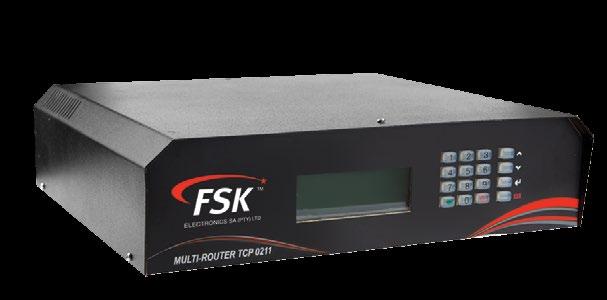
3 1. OVERVIEW The FSK Router 0211 is a high performance Repeater or Base Station for use on the FSK long-range radio and GSM networks. When installed as a base station in the security control room, it will receive alarms from FSK long-range radio transmitters and GSM units It has the facility to display the alarm, print it, and send it to the monitoring computer by means of a serial connection. When installed as a repeater, it will forward alarms from FSK long-range radio transmitters to the control room via either radio, GSM or any TCP/IP broad-band connection to the control room. The Router 0211 is self-contained and has its own power supply and a backup battery. The Router 0211 is programmed using the FSK Router Programming software via a serial port or remotely (if used on the FSK GSM or TCP/IP networks). Some of the Router 0211 settings can be changed via the on-board keypad. 2. FEATURES OF THE TCP MULTI-ROUTER FSK High-performance long-range radio receiver. FSK Radio Transmitter (repeater only). Option of dual 3G high-speed GSM modem. Ethernet TCP/IP port. Large LCD to display alarms or settings. Keypad for changing settings as well as performing diagnostics. On-board power supply with backup battery. Printer Port (parallel). Serial ports for programming as well as connections to a monitoring computer. 2 P a g e
 220V AC Connect the Radio Antenna using a PL259 (UHF) 50Ω RF Connector. Connect the RS232 (monitoring computer) plug to the monitoring computer using the serial cable supplied.")
4 3. INSTALLATION The Router 0211 is connected as shown (ROUTER REAR VIEW) GSM ANTENNAS MTN VODACOM BOOTLOADER SWITCH RS232 PROGRAMMING ETHERNET USB RS232 RADIO ANTENNA MONITORING COMPUTER PRINTER FUSE (DC 10A) 220V AC Connect the Radio Antenna using a PL259 (UHF) 50Ω RF Connector. Connect the RS232 (monitoring computer) plug to the monitoring computer using the serial cable supplied. Plug a printer (if required) into the printer port. Install the 10A fuse into the fuse holder. Plug the Ethernet Connector into the Ethernet Switch (if used). Connect the GSM antennas to the unit. The connectors are the SMA type. Connect the Power input to a 220V AC mains supply. ANTENNA The antenna is crucial to the optimum performance of the Router. Suitable antennas are Folded Dipole (outdoor type) Collinear The antenna should be mounted outdoors on a mast (as high as possible) in order to achieve maximum radio range. The antenna should be connected using RG213 or RG214 cable. RG58 cable is not suitable for runs of more than 10m as it has too much loss. The antenna should be mounted vertically (vertical polarisation) and not horizontally. 3 P a g e
.")
5 GSM ANTENNAS If the Router is fitted with a GSM Module, GSM antennas should be plugged into the unit. The antenna connector is a SMA type. The antenna should preferably be mounted externally to the control room. The antenna should be mounted so that the GSM signal strength is greater than 24 (see the section on GSM). RS232 The RS232 connection is used to send an incoming alarm to the monitoring computer at the control room. The bottom RS232 connector is connected to the computer. The RS232 should be connected using the cable supplied. The RS232 connections are as shown in Appendix A. The Router has three alarm formats which can be transmitted using the serial port, FSK Standard, FSK Extended or FSK7 (Contact ID). Refer to Appendix A. Be sure that the correct format has been chosen (refer to the section on Programming). The monitoring software should be compatible with the selected RS232 format. PRINTER If a printer is required, it is connected via the DB25 (male) to Centronix cable required. A purpose-made printer cable should always be used. Do not attempt to make your own. The standard printer connections are shown in Appendix B. Note that a printer will slow down the operation of receiving a large number of alarms (2+ alarms per second) due to the slow nature of the printer. FUSE The fuse is used to protect the internal circuitry from the battery in the event of a failure. Only use a 20mm glass, 10A, Fast Blow fuse. 4. OPERATION 4 P a g e
6 CONFIGURATION A number of settings on the Router can be changed via the keypad and the LCD. Be careful when changing settings as you may adversely affect the working of the Router and its ability to receive and transmit alarms. 1. To change the configuration of the Router, press the ENTER ( ) key. 2. The menus can be navigated using the UP ( ) and DOWN ( ) cursors. 3. The ENTER key is used to enter a menu or to enter the data. Configuration screen CONFIGURATION MENU See Below DATE/TIME DATE: TIME: The date is entered as CCYY/MM/DD Use the (E) key to advance to the next field Press ENTER when done The time is entered as HH:MM:SS Use the (E) key to advance to the next field Press ENTER when done GSM STATUS For models fitted with a GSM modem: 5 P a g e
7 Press Enter to Display the GSM status: The GSM status will cycle between the statuses of the two SIM cards installed on the GSM modem. The Following information is displayed (per SIM card): DEVICE ID This is the ID of the device on the FSK GSM network SIG Signal Strength (S0 to S31). Minimum allowable = 20 BER Bit Error Rate (E0 to E99) 0 is optimal 99 is no value obtained from the network IP ADDRESS The IP address of this device on the FSK GSM Network GPRS GPRS connected (GPRS-C) /not connected (GPRS-N) SIM The status of the SIM card SIM-OK (SIM card OK) SIM-ER (SIM Card Error) STATE Connected State START (Initialising on GSM network) READY (connected to FSK routing server) GSMREG GSM Registration State GSM-REG (Registered on the GSM network) GSM-OFF (Not Registered) GPRSREG Data Registration State GPRS-REG (Registered on 3G/Edge/GPRS) GPRS-OFF (Not registered on GSM data) 6 P a g e
8 Press the CLEAR button to exit the menu CONFIGURATION MENU: Press Enter to access the configuration menu: IP ADDRESS 7 P a g e The IP address is
9 Enter the IP address with leading zeros, e.g. 10 is entered as 010. Use the (E) key to advance on field. Press Enter when done. SUBNET MASK The Subnet Mask is Enter the Subnet Mask with leading zeros, e.g. 10 is entered as 010. Use the (E) key to advance on field. Press Enter when done. GATEWAY 1 Gateway 1 is Enter the Gateway with leading zeros, e.g. 10 is entered as 010. Use the (E) key to advance on field. Press Enter when done. 8 P a g e
10 GATEWAY 2 Gateway 2 is Enter the Gateway with leading zeros, e.g. 10 is entered as 010. Use the (E) key to advance on field. Press Enter when done. SERIAL OUT The Serial Output format is used to send alarms to the Control Room Computer via the RS232 port. Use the UP and DOWN arrows to cycle between the following Serial Output formats: FSK 7 FSK FSK EXTENDED Refer to Appendix A for the descriptions of the Serial Output formats. FSK 7 is the preferred Serial Format. MAKE SURE THAT THE CORRECT SERIAL FORMAT IS SELECTED OR THE MONITORING COMPUTER WILL NOT RECEIVE ANY ALARMS 9 P a g e
11 BUZZER The buzzer mode can be set to the following: BUZZER MODE BUZZER OFF BUZZER ON ON WITH RELAY SUSTAIN RELAY WITH FUNCTION The buzzer will not sound when alarms are received The Buzzer will sound when an alarm is received When an alarm is received, the Buzzer will turn on briefly The on-board relay will also turn on (for use with an external siren) When an alarm is received, the Buzzer will turn on and stay on. The on-board relay will also turn on (for use with an external siren). The Buzzer and Relay have to be cancelled by pressing the CLR key. Press the UP and DOWN keys to select the required Buzzer operation. Press ENTER when done. SERVER 1 Server 1 is Enter the Server address with leading zeros, e.g. 10 is entered as 010 Use the (E) key to advance on field. 10 P a g e
12 If the Server IP Address is to be entered as a domain name with letters, do the following: Press one of the keys repetitively to select the correct alphabetical character. Use the UP and DOWN keys to move between the fields. Press the (E) key to end the entry (i.e. last character). Press the ENTER key when done. KEY CHARACTER(S) a b c A B C 3 3 d e f D E F 4 4 g h I G H I 5 5 j k l J K L 6 6 m n o M N O 7 7 p q r s P Q R S 8 8 t u v T U V 9 9 w x y z W X Y Z 0 0 /. -, + * ) ( : ; & % $ #! SPACE * : ; < = (E) END OF TEXT Remember to end the Text using the (E) key LIMIT MODE The Limit Mode function will restrict the types of alarms which will be sent from the Router to the Monitoring Computer. The following limits are used: 11 P a g e
13 LIMIT MODE NONE STRICT RECOMMENDED ALARMS RECEIVED All alarms Only panic and Burglary Signals The recommended list of FSK alarm codes. Refer to Appendix B Limit mode set to NONE is not recommended on older radio networks. DHCP The DHCP setting enables or disables DHCP. If DHCP is enabled then the Ethernet will receive an IP address from the network. If disabled then a static IP must be entered as per IP address, subnet mask, gateway 1 and gateway 2 settings described previously on pages 7, 8 and 9. The following options are available: DHCP MODE DHCP ENABLED ON DHCP is enabled for the network OFF DHCP is not enabled static IP s to be used PRINTER 12 P a g e
14 The printer setting enables or disables all signals received to be printed if there is a printer connected to the router s printer port. The following options are available: PRINTER MODE ALARMS PRINTED ON All alarms printed OFF No alarms printed When all the settings have been changed to the desired ones, go back to the Configuration Menu. Use the DOWN key to go down to RESET. Press the ENTER key to save all your new settings. CHANGED SETTINGS ONLY TAKE EFFECT AFTER A RESET. 13 P a g e
15 APPENDIX A - RS232 CONNECTIONS AND PROTOCOL The Router is fitted with a female DB9 RS232 connector which is used to send alarms to the monitoring computer. DB9 FEMALE CONNECTOR PIN FUNCTION 2 RS232 TXD 3 RS232 RXD 5 GND SERIAL CABLE DB9 MALE TXD RXD WIRE LENGTH = 400mm GND (black) RXD TXD DB9 FEMALE COMPUTER FSK STANDARD BAUD RATE: 1200 Stop Bits: 1 Data Bits: 8 Parity: NONE Handshaking: NONE String Format <SOT> Start of Text ASCII Char 2 ACCOUNT 1-5 Account Code (5 ASCII characters, e.g ) INFORMATION 1-3 Alarm Information (3 ASCII characters, e.g. 097) <CR> Carriage Return (ASCII character 13) <LF> Line Feed (ASCII Character 10) <EOT> End of Text (ASCII Character 4) 14 P a g e
16 FSK EXTENDED BAUD RATE: 1200 Stop Bits: 1 Data Bits: 8 Parity: NONE Handshaking: NONE String Format <SOT> Start of Text ASCII Char 2 ACCOUNT 1-5 Account Code (5 ASCII characters, e.g ) INFORMATION 1-3 Alarm Information (3 ASCII characters, e.g. 097) REPEATER 1-2 Repeater Number (2 ASCII characters, e.g. 01) Repeater is set to 31 if the signal is received directly RSSI Relative Signal Strength Indicator ASCII character 0 to 7 (0 = weakest, 7 = Strongest) <CR> Carriage Return (ASCII character 13) <LF> Line Feed (ASCII Character 10) <EOT> End of Text (ASCII Character 4) FSK7 (CONTACT ID) Baud: 9600 Parity: none Stop bits: 1 Data bits: 8 Handshaking: none Base to PC (spaces for readability only) $02 T AAAAA Q CCC PP ZZZ S RR I I NFF $0D $02 -Start of text 2 hex. T -Message type (ASCII) C * AAAAA -5 digit account code (ASCII) Q -Qualifier E, R, S (ASCII) ** CCC -Alarm code 000 to 999 (ASCII) PP -Partition 00 to 99 (ASCII) ZZZ -Zone or user 000 to 999 (ASCII) S -Start code 0 to 7 (ASCII) RR -Repeater ID 00 to 32 (ASCII) I -RSSI Local 0 to 7 (ASCII) (Repeater) I -RSSI Remote 0 to 7 (ASCII) (Transmitter) N - Line Card or slot number A = Line Card 0, I = Line Card 8 FF -Free space = 00 (ASCII) $0D -Carriage Return 13 decimal. * T Only one message type C in use. The ASCII character C means that the alarm codes (CCC) correspond to the ADEMCO 18 contact ID alarm codes. The alarm codes are defined in the SIA document. ** Q Event qualifier: E = new event, R = event restore, S = status report. ***N Line Card or Slot. Identifies the Line Card (slot) from which the alarm comes in the Multi-Router. Slot 0 is sent as A, slot 8 is sent as I Slot 0 is for local messages from router (e.g. heartbeat, power-up etc.) Slots 1 to 8 are used to identify the receiver which received the signal. 15 P a g e
17 APPENDIX B - FSK ALARM CODES The Router 0211 is capable of receiving either FSK Alarms or Contact ID Alarms. If the format of the alarm received is not the same as the serial port protocol selected (see Appendix A) the Router 0211 will convert from the one format to the other. For example, if an alarm is received in the FSK format and the RS232 format is set to FSK7 (Contact ID), the Router 0211 will convert the FSK format alarm to its Contact ID equivalent. If an alarm is received in Contact ID format and the RS232 protocol is set to FSK, the Router 0211 will attempt to convert the alarm to the equivalent FSK code. Note that not all Contact ID codes have an equivalent FSK code. TABLE B1: FSK ALARM CODES AND EQUIVALENT CONTACT ID CONVERSION FSK FSK FSK CONTACT ID PTY LIMIT ALTERNATE CODE DESCRIPTION USE CODE E DESCRIPTION ZONE ALARM TELEM 0 AUTO TEST 602 E Periodic test report Zone 0 NO YES 1 CANCEL BY KEYH E Cancel User 1 NO NO 2 TELEMETRY 2 COMMS RESTORED 357 E Long Range Radio 2 NO NO 3 TELEMETRY E Periodic RF Test 3 NO NO 4 POINTS MISSED 708 E POINTS MISSED 0 NO NO 5 PATROL START LATE 703 E PATROL START LATE 0 NO NO PATROL START ON 6 TIME 702 E PATROL START 0 NO NO 7 GUARD PATROL SLOW 711 E GUARD PATROL SLOW 0 NO NO 8 GUARD PATROL FAST 712 E GUARD PATROL FAST 0 NO NO GUARD FAIL TO START 9 SHIFT 716 E GUARD FAIL TO START SHIFT 0 NO NO 10 PROGRAM COMPLETE 628 E Program Mode Exit 0 NO NO 11 GUARD LATE ON DUTY 707 E GUARD LATE ON DUTY 0 NO NO 12 WRONG ROUTE 718 E WRONG ROUTE 0 NO NO 13 SUPERVISOR ON SITE 140 E Supervisor on site 13 NO NO 14 SUPERVISOR OFF SITE 140 R Supervisor on site 14 NO NO 15 OPEN KEYH E Keyswitch O/C 99 NO NO 16 ELECTRIC FENCE 131 E Perimeter Zone 0 NO YES 17 WATCHDOG RESET 305 E System reset Zone 0 NO NO 18 LOOP TROUBLE RES 332 R Polling loop short Zone 0 NO NO 19 SIREN FUSE RESTORE 321 R Bell 1 0 NO NO 20 FAIL TO REPORT 350 E Communication trouble 0 NO NO 16 P a g e R
18 21 LOOP TROUBLE 141 E Polling loop open Zone 0 NO NO 22 SIREN FUSE FAIL 321 E Bell 1 0 NO NO 23 EMERGENCY 101 E Personal Emergency Zone 0 YES YES 24 REMOTE PANIC 101 E Personal Emergency Zone 0 YES YES 25 PANIC 120 E Panic Zone 0 YES YES 26 DURESS 121 E Duress User 0 YES YES 27 BATT VOLTAGE LOW 302 E Low system battery Zone 0 NO YES 28 BATT VOLTAGE REST 302 R Low system battery Zone 0 NO YES 29 AC POWER FAIL 301 E AC Loss Zone 0 NO YES 30 AC POWER RESTORED 301 R AC Loss Zone 0 NO YES TRASNMTR LOCKED Long Range Radio emitter 31 ON 353 E fault Zone 0 NO YES 32 HOLD UP 121 E Duress User 0 NO YES GUARD ON 33 OPEN BY KEYH 1 DUTY 400 E Open/Close User 1 NO YES 34 OPEN BY KEYH E Open/Close User 2 NO NO 35 OPEN BY KEYH E Open/Close User 3 NO NO 36 OPEN BY KEYH E Open/Close User 4 NO NO 37 OPEN BY KEYH E Open/Close User 5 NO NO 38 OPEN BY KEYH E Open/Close User 6 NO NO 39 OPEN BY KEYH E Open/Close User 7 NO NO 40 OPEN BY KEYH E Open/Close User 8 NO NO 41 OPEN BY KEYH E Open/Close User 9 NO NO 42 OPEN BY KEYH E Open/Close User 10 NO NO 43 OPEN BY KEYH E Open/Close User 11 NO NO 44 OPEN BY KEYH E Open/Close User 12 NO NO 45 OPEN BY KEYH E Open/Close User 13 NO NO 46 OPEN BY KEYH E Open/Close User 14 NO NO 47 OPEN BY KEYH E Open/Close User 15 NO NO 48 OPEN BY KEYH E Open/Close User 16 NO NO 49 OPEN BY KEYH E Open/Close User 17 NO NO 50 OPEN BY KEYH E Open/Close User 18 NO NO 51 OPEN BY KEYH E Open/Close User 19 NO NO 52 OPEN BY KEYH E Open/Close User 20 NO NO 53 PARTIAL ARM 456 R Partial Arm 0 NO NO Manual trigger test report 54 MANUAL TEST 601 E Zone 0 NO NO 55 PROGRAM COMPLETE 628 E Program mode exit Zone 0 NO NO 56 PERIPHERAL TROUBLE 330 E System Peripheral trouble Zone 0 NO NO Communication trouble 57 COMS TROUBLE 350 E Zone 0 NO NO 58 PERIODIC TEST 602 E Periodic test report Zone 0 NO NO 59 TELEMETRY E Periodic RF Transmission 59 NO NO 60 TELEMETRY E Periodic RF Transmission 60 NO NO 61 TELEMETRY E Periodic RF Transmission 61 NO NO 17 P a g e Zone
19 62 TELEMETRY E Periodic RF Transmission 62 NO NO 63 TELEMETRY E Periodic RF Transmission 63 NO NO 64 TELEMETRY E Periodic RF Transmission 64 NO NO 65 CLOSE BY KEYH 1 GUARD OFF DUTY 400 R Open/Close User 1 NO YES 66 CLOSE BY KEYH R Open/Close User 2 NO NO 67 CLOSE BY KEYH R Open/Close User 3 NO NO 68 CLOSE BY KEYH R Open/Close User 4 NO NO 69 CLOSE BY KEYH R Open/Close User 5 NO NO 70 CLOSE BY KEYH R Open/Close User 6 NO NO 71 CLOSE BY KEYH R Open/Close User 7 NO NO 72 CLOSE BY KEYH R Open/Close User 8 NO NO 73 CLOSE BY KEYH R Open/Close User 9 NO NO 74 CLOSE BY KEYH R Open/Close User 10 NO NO 75 CLOSE BY KEYH R Open/Close User 11 NO NO 76 CLOSE BY KEYH R Open/Close User 12 NO NO 77 CLOSE BY KEYH R Open/Close User 13 NO NO 78 CLOSE BY KEYH R Open/Close User 14 NO NO 79 CLOSE BY KEYH R Open/Close User 15 NO NO 80 CLOSE BY KEYH R Open/Close User 16 NO NO 81 CLOSE BY KEYH R Open/Close User 17 NO NO 82 CLOSE BY KEYH R Open/Close User 18 NO NO 83 CLOSE BY KEYH R Open/Close User 19 NO NO 84 CLOSE BY KEYH R Open/Close User 20 NO NO 85 TELEMETRY E General Alarm Zone 85 NO NO 86 PRINTER OFF-LINE 336 E Local printer failure Zone 0 NO YES 87 RAM OR I/O ERROR 303 E RAM Checksum bad Zone 0 NO YES Manual trigger test report 88 SYS TEST BY CNTR 601 E Zone 0 NO NO 89 CLOSE BY KEYH R Keyswitch O/C User 99 NO NO 90 TELEMETRY E Periodic RF Transmission 90 NO NO 91 TELEMETRY E Periodic RF Transmission 91 NO NO 92 TELEMETRY E Periodic RF Transmission 92 NO NO 93 TELEMETRY E Periodic RF Transmission 93 NO NO 94 TELEMETRY E Periodic RF Transmission 94 NO NO 95 TELEMETRY E Periodic RF Transmission 95 NO NO 96 TELEMETRY E Periodic RF Transmission 96 NO NO 97 BURGLARY ZONE E Burglary Zone 1 YES YES 98 BURGLARY ZONE E Burglary Zone 2 YES YES 99 BURGLARY ZONE E Burglary Zone 3 YES NO 100 BURGLARY ZONE E Burglary Zone 4 YES NO 101 BURGLARY ZONE E Burglary Zone 5 YES NO 102 BURGLARY ZONE E Burglary Zone 6 YES NO 103 BURGLARY ZONE E Burglary Zone 7 YES NO 104 BURGLARY ZONE E Burglary Zone 8 YES NO 18 P a g e
20 105 BURGLARY ZONE E Burglary Zone 9 YES NO 106 BURGLARY ZONE E Burglary Zone 10 YES NO 107 BURGLARY ZONE E Burglary Zone 11 YES NO 108 BURGLARY ZONE E Burglary Zone 12 YES NO 109 BURGLARY ZONE E Burglary Zone 13 YES NO 110 BURGLARY ZONE E Burglary Zone 14 YES NO 111 BURGLARY ZONE E Burglary Zone 15 YES NO 112 BURGLARY ZONE E Burglary Zone 16 YES NO 113 BURGLARY ZONE E Burglary Zone 17 YES NO 114 BURGLARY ZONE E Burglary Zone 18 YES NO 115 BURGLARY ZONE E Burglary Zone 19 YES NO 116 BURGLARY ZONE E Burglary Zone 20 YES NO 117 BURGLARY ZONE E Burglary Zone 21 YES NO 118 BURGLARY ZONE E Burglary Zone 22 YES NO 119 BURGLARY ZONE E Burglary Zone 23 YES NO 120 BURGLARY ZONE E Burglary Zone 24 YES NO 121 BURGLARY ZONE E Burglary Zone 25 YES NO 122 BURGLARY ZONE E Burglary Zone 26 YES NO 123 BURGLARY ZONE E Burglary Zone 27 YES NO 124 BURGLARY ZONE E Burglary Zone 28 YES NO 125 BURGLARY ZONE E Burglary Zone 29 YES NO 126 BURGLARY ZONE E Burglary Zone 30 YES NO 127 BURGLARY ZONE E Burglary Zone 31 YES NO 128 BURGLARY ZONE E Burglary Zone 32 YES NO 129 ISOLATE ZONE E Zone/Sensor bypass Zone 1 NO NO 130 ISOLATE ZONE E Zone/Sensor bypass Zone 2 NO NO 131 ISOLATE ZONE E Zone/Sensor bypass Zone 3 NO NO 132 ISOLATE ZONE E Zone/Sensor bypass Zone 4 NO NO 133 ISOLATE ZONE E Zone/Sensor bypass Zone 5 NO NO 134 ISOLATE ZONE E Zone/Sensor bypass Zone 6 NO NO 135 ISOLATE ZONE E Zone/Sensor bypass Zone 7 NO NO 136 ISOLATE ZONE E Zone/Sensor bypass Zone 8 NO NO 137 ISOLATE ZONE E Zone/Sensor bypass Zone 9 NO NO 138 ISOLATE ZONE E Zone/Sensor bypass Zone 10 NO NO 139 ISOLATE ZONE E Zone/Sensor bypass Zone 11 NO NO 140 ISOLATE ZONE E Zone/Sensor bypass Zone 12 NO NO 141 ISOLATE ZONE E Zone/Sensor bypass Zone 13 NO NO 142 ISOLATE ZONE E Zone/Sensor bypass Zone 14 NO NO 143 ISOLATE ZONE E Zone/Sensor bypass Zone 15 NO NO 144 ISOLATE ZONE E Zone/Sensor bypass Zone 16 NO NO 145 ISOLATE ZONE E Zone/Sensor bypass Zone 17 NO NO 146 ISOLATE ZONE E Zone/Sensor bypass Zone 18 NO NO 147 ISOLATE ZONE E Zone/Sensor bypass Zone 19 NO NO 148 ISOLATE ZONE E Zone/Sensor bypass Zone 20 NO NO 19 P a g e
21 149 ISOLATE ZONE E Zone/Sensor bypass Zone 21 NO NO 150 ISOLATE ZONE E Zone/Sensor bypass Zone 22 NO NO 151 ISOLATE ZONE E Zone/Sensor bypass Zone 23 NO NO 152 ISOLATE ZONE E Zone/Sensor bypass Zone 24 NO NO 153 GUARD FIRE 110 E Fire 0 NO NO ASSISTANCE 154 REQUIRED 704 E ASSISTANCE REQUIRED 0 NO NO 155 GUARD PATROL FAIL 705 E GUARD PATROL FAIL 0 NO YES 156 GUARD SYSTEM ON 715 E GUARD SYSTEM ON 0 NO YES 157 GUARD SYSTEM OFF 714 E GUARD SYSTEM OFF 0 NO YES 158 GUARD TAMPER 137 E Tamper 0 NO NO 159 FAIL TO START PATROL 701 E FAIL TO START PATROL 0 NO NO 160 GUARD PATROL COMP 713 E GUARD PATROL COMP 0 NO YES 161 RESTORAL ZONE R Burglary Zone 1 NO NO 162 RESTORAL ZONE R Burglary Zone 2 NO NO 163 RESTORAL ZONE R Burglary Zone 3 NO NO 164 RESTORAL ZONE R Burglary Zone 4 NO NO 165 RESTORAL ZONE R Burglary Zone 5 NO NO 166 RESTORAL ZONE R Burglary Zone 6 NO NO 167 RESTORAL ZONE R Burglary Zone 7 NO NO 168 RESTORAL ZONE R Burglary Zone 8 NO NO 169 RESTORAL ZONE R Burglary Zone 9 NO NO 170 RESTORAL ZONE R Burglary Zone 10 NO NO 171 RESTORAL ZONE R Burglary Zone 11 NO NO 172 RESTORAL ZONE R Burglary Zone 12 NO NO 173 RESTORAL ZONE R Burglary Zone 13 NO NO 174 RESTORAL ZONE R Burglary Zone 14 NO NO 175 RESTORAL ZONE R Burglary Zone 15 NO NO 176 RESTORAL ZONE R Burglary Zone 16 NO NO 177 RESTORAL ZONE R Burglary Zone 17 NO NO 178 RESTORAL ZONE R Burglary Zone 18 NO NO 179 RESTORAL ZONE R Burglary Zone 19 NO NO 180 RESTORAL ZONE R Burglary Zone 20 NO NO 181 RESTORAL ZONE R Burglary Zone 21 NO NO 182 RESTORAL ZONE R Burglary Zone 22 NO NO 183 RESTORAL ZONE R Burglary Zone 23 NO NO 184 RESTORAL ZONE R Burglary Zone 24 NO NO 185 RESTORAL ZONE R Burglary Zone 25 NO NO 186 KEYPAD PANIC 120 E Panic Zone 0 NO NO 187 KEYPAD TAMPER 137 E Tamper Zone 0 NO NO 188 EPROM ERROR 304 E ROM checksum bad Zone 0 NO NO 189 SYSTEM TROUBLE 300 E System Trouble Zone 0 NO NO 190 FIRE SYSTEM TEST 604 E Fire test User 0 NO NO 191 FIRE SUPERVISORY 200 E Fire Supervisory Zone 0 NO NO 192 TELEMETRY E General Alarm 192 NO NO 20 P a g e
22 193 FIRE ZONE E Fire Zone 1 NO YES 194 ISOLATE ZONE E Zone/Sensor bypass Zone 25 NO NO 195 ISOLATE ZONE E Zone/Sensor bypass Zone 26 NO NO 196 ISOLATE ZONE E Zone/Sensor bypass Zone 27 NO NO 197 ISOLATE ZONE E Zone/Sensor bypass Zone 28 NO NO 198 ISOLATE ZONE E Zone/Sensor bypass Zone 29 NO NO 199 ISOLATE ZONE E Zone/Sensor bypass Zone 30 NO NO 200 ISOLATE ZONE E Zone/Sensor bypass Zone 31 NO NO 201 ISOLATE ZONE E Zone/Sensor bypass Zone 32 NO NO 202 RESTORAL ZONE R Burglary Zone 26 NO NO 203 RESTORAL ZONE R Burglary Zone 27 NO NO 204 RESTORAL ZONE R Burglary Zone 28 NO NO 205 RESTORAL ZONE R Burglary Zone 29 NO NO 206 RESTORAL ZONE R Burglary Zone 30 NO NO 207 RESTORAL ZONE R Burglary Zone 31 NO NO 208 RESTORAL ZONE R Burglary Zone 32 NO NO 209 FAULT ZONE E Sensor trouble Zone 25 NO NO 210 FAULT ZONE E Sensor trouble Zone 26 NO NO 211 FAULT ZONE E Sensor trouble Zone 27 NO NO 212 FAULT ZONE E Sensor trouble Zone 28 NO NO 213 FAULT ZONE E Sensor trouble Zone 29 NO NO 214 FAULT ZONE E Sensor trouble Zone 30 NO NO 215 FAULT ZONE E Sensor trouble Zone 31 NO NO 216 FAULT ZONE E Sensor trouble Zone 32 NO NO 217 DELAYED ALARM 130 E Burglary Zone 3 YES YES 218 AUXILIARY ALARM 140 E General Alarm Zone 0 NO NO 219 BELL TROUBLE 320 E Sounder/Relay Zone 0 NO NO BELL TROUBLE 220 RESTORE 320 R Sounder/Relay Zone 0 NO NO 221 TIMER TEST 602 E Periodic test report Zone 0 NO NO 222 GENERAL ALARM 140 E General Alarm 0 NO NO 223 UNWANTED CARRIER 344 E RF Receiver Jam Detect Zone 0 NO YES 224 MEDICAL EMERGENCY 100 E Medical Zone 0 NO YES 225 FAULT ZONE E Sensor trouble Zone 1 NO NO 226 FAULT ZONE E Sensor trouble Zone 2 NO NO 227 FAULT ZONE E Sensor trouble Zone 3 NO NO 228 FAULT ZONE E Sensor trouble Zone 4 NO NO 229 FAULT ZONE E Sensor trouble Zone 5 NO NO 230 FAULT ZONE E Sensor trouble Zone 6 NO NO 231 FAULT ZONE E Sensor trouble Zone 7 NO NO 232 FAULT ZONE E Sensor trouble Zone 8 NO NO 233 FAULT ZONE E Sensor trouble Zone 9 NO NO 234 FAULT ZONE E Sensor trouble Zone 10 NO NO 235 FAULT ZONE E Sensor trouble Zone 11 NO NO 236 FAULT ZONE E Sensor trouble Zone 12 NO NO 21 P a g e
23 237 FAULT ZONE E Sensor trouble Zone 13 NO NO 238 FAULT ZONE E Sensor trouble Zone 14 NO NO 239 FAULT ZONE E Sensor trouble Zone 15 NO NO 240 FAULT ZONE E Sensor trouble Zone 16 NO NO 241 FAULT ZONE E Sensor trouble Zone 17 NO NO 242 FAULT ZONE E Sensor trouble Zone 18 NO NO 243 FAULT ZONE E Sensor trouble Zone 19 NO NO 244 FAULT ZONE E Sensor trouble Zone 20 NO NO 245 FAULT ZONE E Sensor trouble Zone 21 NO NO 246 FAULT ZONE E Sensor trouble Zone 22 NO NO 247 FAULT ZONE E Sensor trouble Zone 23 NO NO 248 FAULT ZONE E Sensor trouble Zone 24 NO NO 249 TAMPER 137 E Tamper Zone 0 NO NO 250 POWER UP 301 R AC Loss Zone 0 NO YES 251 SYSTEM COMMAND E Periodic RF Transmission 251 NO NO 252 GPRS FAILED 350 E Comms Trouble 252 NO NO 253 GPRS RESTORED 350 R Comms Trouble 253 NO NO 254 NOT USED MINIBASE STUNNED 140 E General Alarm 254 NO NO RED - NON STANDARD TABLE B2 - ADEMCO CODES TO FSK CODES CONVERSIONS When the Router 0211 receives an Ademco Contact ID format alarm and the RS232 format is set to FSK or FSK Extended, the alarm is converted to the equivalent FSK format alarm. ADEMCO CODE 22 P a g e ADEMCO DESCRIPTION FSK CODE ON EVENT DESCRIPTION 100 MEDICAL 224 MEDICAL EMERGENCY 101 PERSONAL EMERGENCY 24 REMOTE PANIC 110 FIRE 193 FIRE ZONE SMOKE 193 FIRE ZONE COMBUSTION 193 FIRE ZONE WATER FLOW 193 FIRE ZONE HEAT 193 FIRE ZONE PULL STATION 193 FIRE ZONE DUCT 193 FIRE ZONE FLAME 193 FIRE ZONE 1 FSK CODE ON RESTORAL 118 NEAR ALARM BURG ZONE 1 TO , PANIC 25 PANIC 121 DURESS 26 DURESS 122 SILENT 25 PANIC 123 AUDIBLE 25 PANIC 130 BURGLARY BURG ZONE 1 TO , DESCRIPTION RESTORAL ZONE 1-24, RESTORAL ZONE 1-24, 26-32
24 131 PERIMETER BURG ZONE 1 TO , INTERIOR BURG ZONE 1 TO , HR (SAFE) BURG ZONE 1 TO , ENTRY/EXIT BURG ZONE 1 TO , DAY/NIGHT BURG ZONE 1 TO , OUTDOOR BURG ZONE 1 TO , TAMPER 249 TAMPER 138 NEAR ALARM BURG ZONE 1 TO , GENERAL ALARM 222 GENERAL ALARM 141 POLLING LOOP OPEN 21 LOOP TROUBLE 142 POLLING LOOP SHORT 21 LOOP TROUBLE , FAULT ZONE 1-24, SENSOR TAMPER FOIL BREAK 189 SYSTEM TROUBLE 156 DAY TROUBLE 189 SYSTEM TROUBLE 200 FIRE SUPERVISORY 191 FIRE SUPERVISORY 201 LOW WATER PRESSIURE 191 FIRE SUPERVISORY 202 LOW CO2 191 FIRE SUPERVISORY 203 GATE VALVE SENSOR 191 FIRE SUPERVISORY 205 PUMP ACTIVATED 191 FIRE SUPERVISORY 206 PUMP FAILURE 191 FIRE SUPERVISORY 300 SYSTEM TROUBLE 189 SYSTEM TROUBLE 301 AC LOSS 29 AC POWER FAIL LOW SYSTEM BATTERY 27 BATT VOLTAGE LOW 303 RAM CHECKSUM BAD 87 RAM OR I/O ERROR 304 ROM CHECKSUM BAD 87 RAM OR I/O ERROR 305 SYSTEM RESET 189 SYSTEM TROUBLE 306 PANEL PROGRAMMING CHANGED 50 OPEN BY K/H SELF-TEST FAILURE 189 SYSTEM TROUBLE 308 SYSTEM SHUTDOWN 189 SYSTEM TROUBLE 309 BATTERY TEST FAILURE 189 SYSTEM TROUBLE 310 GROUND FAULT 189 SYSTEM TROUBLE 320 SOUNDER/RELAY 219 BELL TROUBLE BELL BELL TROUBLE BELL BELL TROUBLE TROUBLE RELAY 219 BELL TROUBLE REVERSING RELAY 219 BELL TROUBLE SYSTEM PERIPHERAL TROUBLE 56 PERIPHERAL TROUBLE 331 POLLING LOOP OPEN 56 PERIPHERAL TROUBLE 23 P a g e RESTORAL ZONE 1-24, RESTORAL ZONE 1-24, RESTORAL ZONE 1-24, RESTORAL ZONE 1-24, RESTORAL ZONE 1-24, RESTORAL ZONE 1-24, RESTORAL ZONE 1-24, AC POWER RESTORED BELL TROUBLE RESTORE BELL TROUBLE RESTORE BELL TROUBLE RESTORE BELL TROUBLE RESTORE BELL TROUBLE RESTORE
25 332 POLLING LOOP SHORT 56 PERIPHERAL TROUBLE 333 EXPANSION MODULE FAILURE 56 PERIPHERAL TROUBLE 334 REPEATER FAILURE 56 PERIPHERAL TROUBLE 335 LOCAL PRINTER OUT OF PAPER 56 PERIPHERAL TROUBLE 336 LOCAL PRINTER FAILURE 56 PERIPHERAL TROUBLE 350 COMMUNICATIONS TROUBLE 57 COMS TROUBLE 2 TELEMETRY TELCO FAULT 1 57 COMS TROUBLE 352 TELCO FAULT 2 57 COMS TROUBLE 353 LONG RANGE RADIO TX FAULT 57 COMS TROUBLE FAILURE TO COMMUNICATE 354 EVENT 57 COMS TROUBLE 355 LOSS OF RADIO SUPERVISION 57 COMS TROUBLE 356 LOSS OF CENTRAL POLLING 57 COMS TROUBLE 370 PROTECTION LOOP 189 SYSTEM TROUBLE 371 PROTECTION LOOP OPEN 189 SYSTEM TROUBLE 372 PROTECTION LOOP SHORT 189 SYSTEM TROUBLE 373 FIRE TROUBLE 189 SYSTEM TROUBLE 380 SENSOR TROUBLE 225 FAULT ZONE LOSS OF SUPERVISION-RF 189 SYSTEM TROUBLE 382 LOSS OF SUPERVISION-RPM 189 SYSTEM TROUBLE 383 SENSOR TAMPER 225 FAULT ZONE RF LOW BATTERY 189 SYSTEM TROUBLE 400 OPEN/CLOSE OPEN BY K/H CLOSE BY K/H O/C BY USER OPEN BY K/H CLOSE BY K/H GROUP O/C OPEN BY K/H CLOSE BY K/H AUTOMATIC O/C OPEN BY K/H CLOSE BY K/H DEFERRED O/C OPEN BY K/H CLOSE BY K/H CANCEL 1 CANCEL BY K/H REMOTE ARM/DISARM 49 OPEN BY K/H CLOSE BY K/H QUICK ARM 51 OPEN BY K/H CLOSE BY K/H 19 TELEMETRY 15/OPEN 409 KEYSWITCH O/C 15 K/H CLOSE BY K/H PARTIAL ARM 53 PARTIAL ARM 551 DIALLER DISABLED 52 OPEN BY K/H RADIO TRANSMITTER DISABLED 52 OPEN BY K/H ZONE/SENSOR BYPASS , ISOLATE ZONE 1-24, , , ISOLATE ZONE 1-24, 571 FIRE BYPASS , , ISOLATE ZONE 1-24, HOUR ZONE BYPASS , , ISOLATE ZONE 1-24, 573 BURG. BYPASS , , ISOLATE ZONE 1-24, 574 GROUP BYPASS , MANUAL TEST TRIGGER REPORT 54 MANUAL TEST 602 PERIODIC TEST REPORT 58 PERIODIC TEST RESTORAL ZONE 1-24, RESTORAL ZONE 1-24, RESTORAL ZONE 1-24, RESTORAL ZONE 1-24, RESTORAL ZONE 1-24, P a g e
26 604 FIRE TEST 190 FIRE YSTEM TEST 627 PROGRAM MODE ENTRY 55 PROGRAM COMPLETE PROGRAM MODE EXIT 55 PROGRAM COMPLETE 55 NON- NOT STANDARD SENT BY FOR GMU TX75X Guard fail to start timer (patrol GUARD FAIL TO START 701 lead time) 159 PATROL TELE 6/ PATROL START 702 Patrol start tag 6 ON TIME 703 Patrol start tag late 5 PATROL START LATE ASSISTANCE 704 Guard requested assistance 154 REQUIRED 705 Guard fail to return timer 155 GUARD PATROL FAIL GUARD PATROL 706 Guard late return tag 160 COMPLETE 707 Guard late on duty 11 GUARD LATE ON DUTY 708 Points read, points missed 4 POINTS MISSED 709 Points read points slow 7 GUARD PATROL SLOW 710 Points read points fast 8 GUARD PATROL FAST 711 Points read Overall walk slow 7 GUARD PATROL SLOW 712 Points read Overall walk fast 8 GUARD PATROL FAST GUARD PATROL 713 Points read points OK 160 COMPLETE 714 Guard off duty 157 GUARD SYSTEM OFF 715 Guard on duty 156 GUARD SYSTEM ON GUARD FAIL TO START 716 Guard off duty timer 9 SHIFT 717 SUPERVISOR ON DUTY 13 SUPERVISOR ON SITE Power up 13 SUPERVISOR ON SITE 719 GUARD SYSTEM POWER-UP 250 POWER UP PROGRAM COMPLETE PROGRAM COMPLETE SUPERVISOR SITE OFF 25 P a g e
27 APPENDIX C - PRINTER CONNECTIONS PRINTER - DB25 FEMALE ON ROUTER 0211 DB25 FEMALE FRONT VIEW PIN NO NAME FUNCTION 1 STROBE STROBE PRINTER 2 DO PRINTER DATA 0 3 D1 PRINTER DATA 1 4 D2 PRINTER DATA 2 5 D3 PRINTER DATA 3 6 D4 PRINTER DATA 4 7 D5 PRINTER DATA 5 8 D6 PRINTER DATA 6 9 D7 PRINTER DATA 7 10 PACK PRINTER ACKNOWLEDGE 11 PBUSY PRINTER BUSY 12 POUT PAPER OUT 13 PSEL PRINTER SELECT PERR PRINTER ERROR 16 PINIT PRINTER INITIALISE 17 PSELPRN PRINTER SELECTED GND GROUND 26 P a g e
28 APPENDIX D - ROUTER SPECIFICATIONS Receiver Radio Specifications Radio Performance tested to : ETSI EMI Tested to : ETSI EN 301 Safety to : EN Mode of Operation : FM Channel Spacing : 12,5kHz Frequency of Operation : 135 to 175MHz Frequency Error : <1 khz (0 to 55 C) Spurious Conducted Components : < -56 dbm (9 khz to 1GHz) < -50 dbm (1GHz to 4GHz) Adjacent Channel Selectivity : < -70dB Intermodulation : <-70dB (ETSI) Antenna : PL259 (UHF) 50Ω Sensitivity (decode) : < -118dBm (99% decode probability) Receiver Transmitter Specifications (if fitted) Radio Performance tested to : ETSI EMI Tested to : ETSI EN 301 Safety to : EN Mode of Operation : FM Channel Spacing : 12,5kHz Frequency of Operation : 135 to 175MHz Frequency Error : <1 khz (0 to 55 C) Spurious Conducted Components : < -56 dbm (9 khz to 1GHz) < -50 dbm (1GHz to 4GHz) Adjacent Channel Selectivity : < -70dB Intermodulation : <-70dB (ETSI) Antenna : PL259 (UHF) 50Ω Sensitivity (decode) : < -118dBm (99% decode probability) Power Requirements 220V AC : < 2.5W Active Or 12V DC (11V to 14V) : < 200mA Fuse : 10A 20mm Fast Blow 27 P a g e
29 LIMITED WARRANTY Limitations of Security Products: Security products and alarm systems do not offer guaranteed protection against burglary, fire, or other emergencies. They may fail to warn for diverse reasons, including (but not limited to): power failure, dead batteries, improper installation, coverage blind spots, coverage areas overlooked during installation, defeat by technically sophisticated intruders, component failure, or inadequate maintenance. Alarm systems should be checked weekly to ensure that all devices are working properly. AN ALARM SYSTEM IS NOT A SUBSTITUTE FOR INSURANCE. FSK Electronics (Pty) Ltd, warrants its products to be in conformance with its own plans and specifications and to be free from defects in materials and workmanship under normal use and service for twelve months from the date of original purchase. Seller's obligation shall be limited to repairing or replacing, at its option, free of charge for materials or labour, any part which is proved not in compliance with Seller's specifications or proves defective in materials or workmanship under normal use and service. Seller shall have no obligation under this Limited Warranty or otherwise if the product is altered or improperly repaired or serviced by anyone other than Seller. For warranty service, return transportation prepaid, to the manufacturer There are no warranties, expressed or implied, of merchantability, or fitness for a particular purpose or otherwise, which extend beyond the description on the face hereof. In no case shall seller be liable to anyone for any consequential or incidental damages for breach of this or any other warranty, express or implied, or upon any other basis of liability whatsoever, even if the loss or damage is caused by its own negligence or fault. Seller does not represent that the products it sells may not be compromised or circumvented; that the products will prevent any personal injury or property loss by burglary, robbery, fire or otherwise; or that the products will in all cases provide adequate warning or protection. Customer understands that a properly installed and maintained alarm system may only reduce the risk of a burglary, robbery, or fire without warning, but it is not insurance or a guarantee that such will not occur or that there will be no personal injury or property loss as a result. Consequently, seller shall have no liability for any personal injury; property damage or other loss based on a claim the product failed to give any warning. However, if seller is held liable, whether directly or indirectly, for any loss or damage arising under this limited warranty or otherwise, regardless of cause or origin, seller's maximum liability shall not in any case exceed the purchase price of the product, which shall be the complete and exclusive remedy against seller. This warranty replaces any previous warranties and is the only warranty made by Seller on this product. No increase or alteration, written or verbal, of the obligations of this Limited Warranty is authorized. Note: Specifications are subject to change without notice. Patents issued and pending worldwide. 28 P a g e
30 14 Richard Road, Industria North Johannesburg, South Africa T: +27 (0) E: Innovative technology by FSK Electronics CALL CENTER:
installation & operation manual
 installation & operation manual TABLE OF CONTENTS INTRODUCTION... 2 FEATURES... 2 PROGRAMMING CONTACT ID... 3 INSTALLATION... 3 OPENING THE HAWK COVER... 3 POWER SUPPLY... 5 CHECK AC... 5 DRY CONTACTS
CONTACT ID REPORT CODES
 CONTACT ID REPORT CODES PREFIX - E - ACTIVATION PREFIX - R - RESTORAL 100 Medical Zone 101 Personal Emergency Zone 102 Fail to report in Zone Fire Alarms 110 110 Fire Zone 111 Smoke Zone 112 Combustion
Contact ID as of 2/2/2015
 Contact ID as of 2/2/2015 100 Medical Zone A non-specific medical exists 101 Personal Emergency Zone Emergency Assistance request 102 Fail to report in Zone A user has failed to activate a monitoring device
Contact ID as of 11/28/2018
 Contact ID as of 11/28/2018 100 Medical Zone A non-specific medical exists 101 Personal Emergency Zone Emergency Assistance request 102 Fail to report in Zone A user has failed to activate a monitoring
GLOBAL. InstallatIon & operation manual
 InstallatIon & operation manual INDEX 1. INTRODUCTION... 5 2. FEATURES AND FUNCTIONS 2.1 Reporting Options... 2.2 Interfaces... 2.3 Programming... 2.4 Indicators and Controls...... 6 6 6 6 6 3. INSTALLATION...
PROGRAMMING GUIDE SPECTRA CONTROL PANELS V , 1725EX, 1728 AND 1728EX 1755, 1755EX, 1758, AND 1758EX
 PROGRAMMING GUIDE SPECTRA CONTROL PANELS V1.2 1725, 1725EX, 1728 AND 1728EX 1755, 1755EX, 1758, AND 1758EX TABLE OF CONTENTS HOW DO I PROGRAM THE SYSTEM?... 4 Single Digit Data Entry Method (Hexadecimal
ADEMCO CONTACT ID REPORTING (revised )
") ADEMCO CONTACT ID REPORTING (revised 7-9-2004) Contact ID reporting takes the following format: CCCC Q EEE GG ZZZ CCCC = customer (subscriber account number) Q = event qualifier, E = new event, R = restore
ADEMCO CONTACT ID REPORTING (revised 7-9-2004) Contact ID reporting takes the following format: CCCC Q EEE GG ZZZ CCCC = customer (subscriber account number) Q = event qualifier, E = new event, R = restore
MG Partition 64-Zone Wireless Console with GPRS/GSM Version 1.6. Section Programming Guide
 MG6250 2-Partition 64-Zone Wireless Console with GPRS/GSM Version.6 Section Programming Guide Things You Need to Know About this Programming Guide The MG6250 All-in-one Wireless Console can be programmed
All-In-One Wireless Security System V3.2 Programming Guide. Model # MG6130 / MG6160
 All-In-One Wireless Security System V3.2 Programming Guide Model # MG6130 / MG6160 We hope this product performs to your complete satisfaction. Should you have any questions or comments, please visit www.paradox.com
External Wireless Sounder
 External Wireless Sounder Model: WL RWS401 Installation and Programming Instructions Table of Contents Introduction... 3 Operational Functions... 3 Alarm / Tamper Indication... 3 Low Battery Indication...
600 Range Dialer Installation Manual. Version 1.0
 600 Range Dialer Installation Manual Version 1.0 The information contained is supplied without liability for any errors or omissions. No part may be reproduced or used except as authorised by contract
HEXA PROGRAMMING: STREAMLINED SECTION PROGRAMMING
 -961212-0004 SOFTWARE VERSION 3.10 CONTROL PANEL RESET: Installer lock must be unlocked. ( 058: enter any value other than 147) Power down reset (1) Remove battery and AC to power down the unit. (2) Connect
0$(6752 0$(6752. Programming Guide. 6 and 10 Zone Alarm Control Panel ,1752'8&7,21 +(;$ 352*5$00,1* 675($0/,1(' 6(&7,21 352*5$00,1* FIGURE 1 FIGURE 2
 0$(6752 0$(6752 6 and 10 Zone Alarm Control Panel Programming Guide,1752'8&7,21 The Maestro-600 and Maestro-1000 alarm control panels enable reduced number of programming steps. End-users can access most
CC408. Quick Reference Guide Solution 880
 CC408 EN Quick Reference Guide Solution 880 CC408 Quick Reference Guide Notices EN 2 Copyright Notice Unless otherwise indicated, this publication is the copyright of Bosch Security Systems Pty Ltd ( Bosch
PowerWave-16. Users Operating and Programming Guide Version P/N Rev. B N.A July 2002
 ELECTRONIC ENGINEERING LTD. PowerWave-16 16 zone Control panel Communicator Users Operating and Programming Guide Version 6.20 P/N 7121240 Rev. B N.A July 2002 Contents Introduction...4 Meet the Crow Alarm
Table of Contents. All-In-One Wireless Security System V1.3. Programming Guide. Model # MG-6060 / MG-6030
 All-In-One Wireless Security System V1.3 Programming Guide Model # MG-6060 / MG-6030 Table of Contents Things You Should Know... 2 About This Programming Guide... 2 Conventions... 2 Installer Code (Default:
HEXA PROGRAMMING: STREAMLINED SECTION PROGRAMMING
 48ESEP-01 SOFTWARE VERSION 3.10 CONTROL PANEL RESET: Installer lock must be unlocked. (Address 058: enter any value other than 147) Power down reset (1) Remove battery and AC to power down the unit. (2)
2000 Series. Program Entry Guide. Control Panels
 2000 Series EN Program Entry Guide Control Panels 2000 Series Program Entry Guide About This Manual EN 2 About This Manual This guide describes the programming parameters available to the 2000 Series Control
INSTALLATION INSTRUCTIONS
 INSTALLATION INSTRUCTIONS N99V /99 PRM Polarity Reversing Module What is the PRM? The PRM Polarity Reversing Module is used to reverse the polarity of the positive and negative voltages powering smoke
Testing the System. Battery Test. Dialer Test. Fire Drill Test (Code + [#] + 69) One-Man Fire Walk-Test (Code + [#] + 68)
![Testing the System. Battery Test. Dialer Test. Fire Drill Test (Code + [#] + 69) One-Man Fire Walk-Test (Code + [#] + 68)](/thumbs/79/79864325.jpg "Testing the System. Battery Test. Dialer Test. Fire Drill Test (Code + [#] + 69) One-Man Fire Walk-Test (Code + [#] + 68)") F A 1 7 0 0 c Testing the System Battery Test When AC power is present, the FA1700C runs a brief battery test every 60 seconds to determine if there is a battery connected, and runs an extended battery
F A 1 7 0 0 c Testing the System Battery Test When AC power is present, the FA1700C runs a brief battery test every 60 seconds to determine if there is a battery connected, and runs an extended battery
External Wireless Sounder
 External Wireless Sounder WL S50 Installation and Programming Instructions 2 Wireless Sounder Instructions Table of Contents Introduction... 4 Operational Functions... 4 Alarm / Tamper Indication...4 Low
Digiplex System V2.14 / V2.2ACC. Control Panel Programming Guide
 Digiplex System V2.14 / V2.2ACC Control Panel Programming Guide Table of Contents Getting Started...2 What Do I Do First?...2 How Do I Program the Control Panel?...2 Single Digit Entry Method...2 Multiple
CC488. Quick Reference Guide Solution Ultima 880
 CC488 EN Quick Reference Guide Solution Ultima 880 CC488 Quick Reference Guide Notices EN 2 Copyright Notice Unless otherwise indicated, this publication is the copyright of Bosch Security Systems Pty
PART NO: TSMS. Designed in Australia by. Instruction Manual. Factory Car Alarm Upgrade Providing Alarm Notification Via SMS Messaging N517
 1 M o d e l : T r a n s f o r m e r S M S PART NO: TSMS Designed in Australia by Instruction Manual Factory Car Alarm Upgrade Providing Alarm Notification Via SMS Messaging N517 2 Contents Contents...
All-In-One Wireless Security System V1.0. Model # MG Programming Guide
 All-In-One Wireless Security System V1.0 Model # MG-6060 Programming Guide Things You Should Know... 4 About This Programming Guide... 4 Conventions... 4 Installer Code (Default: 0000 / 000000)... 4 Maintenance
Digital Communication Standard - Ademco Contact ID Protocol - for Alarm System Communications
 Digital Communication Standard - Ademco Contact ID Protocol - for Alarm System Communications Sponsor Security Industry Association Copyright 1999 - Ademco Group Publication Order Number: 14085 FOREWORD
DL150 DOWNLOADABLE CONTROL COMMUNICATOR INSTALLATION MANUAL
 DL150 DOWNLOADABLE CONTROL COMMUNICATOR INSTALLATION MANUAL TABLE OF CONTENTS 1. GENERAL DESCRIPTION... 2 2. STANDARD AND OPTIONAL PARTS LIST... 2 3. FEATURE DEFINITIONS... 3 4. TERMINAL DRAWING AND SPECIAL
IRIS Touch Quick Installation & Maintenance Guide. Version 1.0
 IRIS Touch Quick Installation & Maintenance Guide Version 1.0 Page 2 of 16 IRIS Touch Quick Installation & Maintenance Guide Version 1.0 Contents 1. Introduction... 4 2. Product Features... 4 3. Package
Contents. Glossary
 Contents Glossary ------------------------------------------------------------------------------------------------------ 6 1. Introduction to the IDS 1632 -------------------------------------------------------------
First Alert 1200C Installer Notes M. Leuck
 First Alert 2C Installer Notes M. Leuck. Programming can done by standard keypads 2. Enter programming with Installer Code + 8 + + 3. Another method of entering programming: Power system down, then back
CDMAEZ. CDMA Universal Alarm Communicator INSTALLATION & USER S GUIDE
 INSTALLATION & USER S GUIDE 2015 Uplink Security LLC. All rights reserved. No part of this publication may be reproduced or used in any form without permission in writing from Uplink. This includes electronic
AXI LED USER MANUAL (REV. 1.0)
") Security & Home Automation System AXI LED USER MANUAL (REV. 1.0) CONTENTS PREFACE FEATURES LED KEYPAD OUTLOOK 1.0 LIGHT INDICATION 1 2 4 6 CHAPTER 1: ALARM SYSTEM CONTROL 1.0 USING LED KEYPAD 1.0.1 ARMING
Security & Home Automation System AXI LED USER MANUAL (REV. 1.0) CONTENTS PREFACE FEATURES LED KEYPAD OUTLOOK 1.0 LIGHT INDICATION 1 2 4 6 CHAPTER 1: ALARM SYSTEM CONTROL 1.0 USING LED KEYPAD 1.0.1 ARMING
Fratech Multipath-IP
 Rev 2.0 (May 2013) Installer Manual 1 Current Part Numbers: Fratech Multipath-IP E-Link STU PCB & Accessory Kit only In Metal Enclosure with Power Supply 998325-PK 998325-XS Installer Manual This document
MG5000 V2.4 MG5050 V2.4 SP5500 V2.4 SP6000 V2.4 SP7000 V2.4. Programming Guide
 MG5000 V2.4 MG5050 V2.4 SP5500 V2.4 SP6000 V2.4 SP7000 V2.4 Programming Guide We hope this product performs to your complete satisfaction. Should you have any questions or comments, please visit www.paradox.com
Maintenance Manual PC6010. WARNING This manual contains information on limitations regarding product use and function
 WARNING This manual contains information on limitations regarding product use and function and information on the limitations as to liability of the manufacturer. The entire manual should be carefully
Version 1.03 January-2002 USER S MANUAL
 Version 1.03 January-2002 1 USER S MANUAL 2 Version 1.03 January-2002 System Details CUSTOMER:...... PHONE:... FAX:... INSTALLED BY:...... PHONE:... FAX:... MAINTENANCE & SERVICE:...... PHONE:... FAX:...
RANGER 7600 DOWNLOADABLE CONTROL COMMUNICATOR INSTALLATION MANUAL
 RANGER 7600 DOWNLOADABLE CONTROL COMMUNICATOR INSTALLATION MANUAL TABLE OF CONTENTS 1. TABLE OF CONTENTS... P.1 2. GENERAL DESCRIPTION... P.2... 3. STANDARD AND OPTIONAL PARTS LIST... P.2... 4. FEATURE
IRIS Touch 400 & 600 Range Installation Manual. Honeywell Galaxy Range. Version 2.0
 IRIS Touch 400 & 600 Range Installation Manual Honeywell Galaxy Range Version 2.0 Table of Contents 1 System Overview... 4 2 IRIS Touch 440 & 640 PCB Layout... 5 3 Connection & Configuration for Honeywell
Inner Range FE3000S. Serial GSM Modem. P/No: INSTALLATION MANUAL
 Revision 1.0 October. 2014 1 Inner Range FE3000S Serial GSM Modem. P/No: 998306 INSTALLATION MANUAL IMPORTANT NOTE: This Installation Manual is only relevant to Serial GSM Modems utilizing the G-Link PCB.
HEXA PROGRAMMING: STREAMLINED SECTION PROGRAMMING
 -961212-0004 SOFTWARE VERSI 3.10 CTROL PANEL RESET: Installer lock must be unlocked. (Address 058: enter any value other than 147) Power down reset (1) Remove battery and AC to power down the unit. (2)
Type Report Report Date: 1/21/2015
 Type Report Report Date: 1/21/2015 IPRS000101 Paradox IPRS7 CMSI Template Type No Description Action Plan 1 Account Supervision Lost System Alarm 2 Account Supervision Restored Restoral, No Alarm 3 Account
DL100 DOWNLOADABLE CONTROL COMMUNICATOR INSTALLATION MANUAL
 DL100 DOWNLOADABLE CONTROL COMMUNICATOR INSTALLATION MANUAL TABLE OF CONTENTS 1. GENERAL DESCRIPTION...P.2 2. STANDARD AND OPTIONAL PARTS LIST...P.2 3. FEATURE DEFINITIONS...P.3 4. TERMINAL DRAWING AND
All-In-One Wireless Security System V1.0. Model #: MG-6060
 All-In-One Wireless Security System V1.0 Model #: MG-6060 Reference and Installation Manual DRAFT Table of Contents Introduction... 5 About Magellan and this Manual... 5 Conventions... 5 Specifications...
System Programming Guide
 & System Programming Guide Software Versions 4.4 (728ULT) and 4.1 (738ULT) Installer Code (Default - 728 Ultra: 282828; 738 Ultra: 383838) Full access to programming, except user access codes (PINs). No
All-In-One Wireless Security System V1.0. Model #: MG Reference and Installation Manual
 All-In-One Wireless Security System V1.0 Model #: MG-6060 Reference and Installation Manual Table of Contents Introduction... 3 About Magellan and this Manual... 3 Conventions... 3 Specifications... 3
Solution 880 Operators Manual. Issue 1.00
 Solution 880 Operators Manual Issue 1.00 Solution 880 Operators Manual Copyright 1998 by, SYDNEY, AUSTRALIA Document Part Number MA408O Document ISSUE 1.00 Printed 15 June 1998 This documentation is provided
SC-F3G User Manual 1.0
 SC-F3G User Manual 1.0 Table of Contents 1. Introduction... 3 2. Functions... 3 3. Features... 3 4. Package Contents... 3 5. Device Configuration... 4 6. Status LED signals... 5 7. Before You Start...
PERMACONN PM1030 Includes DI300. Installation Manual
 PERMACONN PM1030 Includes DI300 Installation Manual Radio Data Comms Unit 5/20-30 Stubbs Street Silverwater NSW 2128 Telephone: 02 9352 1777 Facsimile: 02 9352 1700 Introduction The PERMACONN system provides
INSTALLATION INSTRUCTIONS and OPERATING GUIDE
 N6484V3 3/96 5827BD and 5827BDE WIRELESS BI-DIRECTIONAL KEYPADS Used with 5800TM Transmitter Module INSTALLATION INSTRUCTIONS and OPERATING GUIDE Unless otherwise indicated, all information in this manual
DIGITAL FRONTIER Voice Alarm System DFA5300 User Manual Version 1 rev2
 DIGITAL FRONTIER Voice Alarm System DFA5300 User Manual Version 1 rev2 About Your Security System Your DF security equipment has been designed to give the greatest possible flexibility and convenience.
Instruction Manual Model Backup Switch, 1 for 8
 Instruction Manual Model 2582-282 Backup Switch, 1 for 8 December 2011, Rev. 0 MODEL 2582 SWITCH CROSS TECHNOLOGIES INC. SWITCH ALARM PSA PSB ALARM OFFLINE ONLINE UNIT STATUS 1 2 3 4 5 6 7 8 BU PROT MODE
IRIS Touch Quick Installation & Maintenance Guide. Version 1.0
 IRIS Touch Quick Installation & Maintenance Guide Version 1.0 Contents 1. Introduction... 3 2. Product Features... 3 3. Package Contents... 4 4. Board Configuration... 4 5. Before You Start... 5 6. Installing
Fratech Multipath-IP STU
 Rev 2.41 (September 2008) Installer Manual 1 Fratech Multipath-IP STU P/Nos: Single SIM: 998304OPT/998304TEL Dual SIM: 998307OPT/998307TEL Installer Manual This document contains a product overview, specifications
D6500 reports are shown in typewriter style letters. For example, AC FAILED indicates the report sent when the panel reports an AC power failure.
 Notice The material and instructions covered in this manual have been carefully checked for accuracy and are presumed to be reliable. However, Radionics, Inc. assumes no responsibility for inaccuracies
IRIS Touch Quick Installation & Maintenance Guide. Version 1.0
 IRIS Touch Quick Installation & Maintenance Guide Version 1.0 Page 2 of 16 IRIS Touch Quick Installation & Maintenance Guide Version 1.0 Contents 1. Introduction...4 2. Product Features...4 3. Package
Fire Burglary Instruments Inc. XL-2G Gold Control/Communicator Installation Training Seminar Rev. 5/96
 Fire Burglary Instruments Inc. XL-2G Gold Control/Communicator Installation Training Seminar Rev. 5/96 XL-2G Gold Product Overview 7 Zones (6 programmable + panic or keyswitch zone) Fast Loop Response
PRODUCT CATALOGUE. Cape Town 18 Darter Road Blue Water Estate Kommetjie. Gauteng 245 Louis Botha Avenue Orchards Johannesburg
 PRODUCT CATALOGUE Cape Town 18 Darter Road Blue Water Estate Kommetjie Luke Fowles - 076 161 8124 luke@providenttech.co.za Frank Fowles - 082 445 1541 frank@providenttech.co.za www.providenttech.co.za
NetworX Series. NX-8 Commercial Fire Panel Installation and Startup
 NetworX Series NX-8 Commercial Fire Panel Installation and Startup 2004 GE Security All rights reserved. Printed in the United States of America. These instructions do not purport to cover all details
Long Range Radio Alarm Transmitter
 W A R N I N G Please refer to the System Installation Manual for information on limitations regarding product use and function and information on the limitations as to liability of the manufacturer. TM
Long Range Radio Alarm Transmitter
 TM Long Range Radio Alarm Transmitter INSTALLATION MANUAL Version 1.3W FEATURES Transmits alarm information to a long range radio network Varitech Transmission Format Note: If automatic SIA is used in
HOME MANAGEMENT GATEWAY
 LS-20 The Universal Box HOME MANAGEMENT GATEWAY OPERATION MANUAL V1.00 INTRODUCTION Thank you for purchasing the LS-20 the Universal Home Management Gateway. By adopting modern embedded system and Cloud
COMMUNICATOR ET08 / ET081
 COMMUNICATOR ET08 / ET081 User Manual v1.2 Safety instructions Please read and follow these safety guidelines in order to maintain safety of operators and people around: GSM communicator ET08 / ET081 (further
RANGER 8600 DOWNLOADABLE CONTROL COMMUNICATOR INSTALLATION MANUAL
 RANGER 8600 DOWNLOADABLE CONTROL COMMUNICATOR INSTALLATION MANUAL TABLE OF CONTENTS GENERAL DESCRIPTION... 2 STANDARD AND OPTIONAL PARTS LIST... 2 PARTS DIAGRAM... 3 TERMINAL DRAWING AND SPECIAL NOTES...
Radionics D4112 Program Sheet
 Programming only by downloading, 5200 Programmer or 5100 "Wand" Programmer Plug programmer in and momentarily short Reset Pin to Terminal 25 to enable program mode 1. Account Account # I I I I I (0 to
L900 series USER MANUAL
 INTRODUCTION The BLUGUARD Control Panel is designed for simple operation yet provides the maximum protection for you. Please read this manual carefully and follow the instructions contained in this book.
EC-P Zone Intruder Alarm System
 EC-P10 10-20 Zone Intruder Alarm System Installation Manual Contents 1. System Overview... 4 System Configuration... 4 Control Panel... 5 Remote Keypads... 5 EC-LED Remote Keypad... 5 EC-LCD Remote Keypad...
AIM TECHNICAL MANUAL PATENT PENDING STOP REMEMBER TO ACTIVATE UNIT BEFORE TESTING. See page 9 for Activation Instructions
 AIM TECHNICAL MANUAL AIM-1450WL WIRELESS PATENT PENDING STOP REMEMBER TO ACTIVATE UNIT BEFORE TESTING See page 9 for Activation Instructions AIM Technical Manual - AIM 1450WL AIM-1450WL WIRELESS ABOUT
Watchguard WGAP864 User Manual
 Watchguard WGAP864 User Manual v1.0 Issued September 2016 1 2 Table of Contents Glossary... 5 1. Introduction to your Watchguard WGAP864... 6 2. Before Operating your Alarm System... 6 3. Understanding
TABLE OF CONTENTS. General Description Standard and Optional Parts List Feature Definitions Comments about the 8600E...
 5$1*(5( DOWNLOADABLE CONTROL COMMUNICATOR INSTALLATION MANUAL TABLE OF CONTENTS General Description... 2 Standard and Optional Parts List... 2 Feature Definitions... 3 Comments about the 8600E... 4 Terminal
MAMI MULTI BASE STATION
 MAMI MULTI BASE STATION INSTALLATION MANUAL SOFTWARE VER. S3C23 MAMI MANUFACTURING AND MINOR INVENTIONS TERRACE ROAD EDENVALE P.O. BOX 2699, EDENVALE, 6 TEL: +27 452 4737 FAX: +27 452 4738 { { { M.A.M.I.
4-PGM Expansion Module
 4-PGM Expansion Module APR3-PGM4 = Default setting SECTION [001] : General Options SECTION [002] : PGM Options Option OFF ON Option OFF ON [1] Future Use N/A N/A [1] PGM1 Deactivation After Deactivation
Security Alarm System Owner's Guide 8 sector CDS Dialler 8-24 sector Control Dialler 8-24 sector Control Securitel Version 1.0 lcopm.
 Security Alarm System Owner's Guide 8 sector CDS Dialler 8-24 sector Control Dialler 8-24 sector Control Securitel Version 1.0 lcopm.pm4 Contents Contents 1 Terms you may neeed to know 2 Keypad Lights
8-zone Expansion Module
 8-zone Expansion Module APR3-ZX8 SECTION [001] : General Options Option OFF ON [1] Tamper Recognition ON = Input 8 (Z8) becomes tamper input = Default setting Disabled Enabled [2] PGM Deactivation After
FW-KP WIRELESS KEYPAD
 ELECTRONIC ENGINEERING LTD. FW-KP WIRELESS KEYPAD INSTALLATION INSTRUCTIONS & USER MANUAL P/N 7101618 Rev. B ME-YS 1 The FW-KP is a wireless remote control keypad for POWERWAVE & RUNNER security and home
RANGER 8980E DOWNLOADABLE CONTROL COMMUNICATOR INSTALLATION MANUAL
 RANGER 8980E DOWNLOADABLE CONTROL COMMUNICATOR INSTALLATION MANUAL TABLE OF CONTENTS GENERAL DESCRIPTION...2 STANDARD AND OPTIONAL PARTS LIST...2 FEATURE DEFINITIONS...3 TERMINAL DRAWING AND SPECIAL NOTES...4
T4000 Security Communicator
 Inner Range T4000 Security Communicator 1 T4000 Security Communicator by Inner Range P/N: 998530 / 998530NZ 998530LT (Lite Version) Installation & Operation Manual. Rev: 1.5 Inner Range Pty. Ltd. www.innerrange.com
Solution 862 Installation Manual ISSUE 1.30
 Solution 862 Installation Manual ISSUE 1.30 MA406I This page has been included for you to cut out and insert into the spine of the folder Solution 862 Installation Manual ISSUE 1.30 (61-2) 9672 1233 Solution
Control/Communicator
 Architectural & Engineering Specifications Control/Communicator 1.0 GENERAL... 2 1.1 SCOPE OF WORK... 2 1.1.1 Introduction... 2 1.2 GENERAL CONDITIONS... 2 1.2.1 After-Sales Support... 2 1.2.2 Quality
UNC100 Integra Manual
 UNC100 Integra Manual New Generation Building Security July 30, 2014 V1.2 Copyright Notice Copyright 1995-2014 by All rights reserved Worldwide. Printed in Canada. This publication has been provided pursuant
User s Guide. SUB-MA7240O-0001.OG.Solution doc. Created: 6/05/03. Last Updated: 23/09/03. MA7240AO-0001 Version 1.0
 User s Guide SUB-MA7240O-0001.OG.Solution40-111.doc Created: 6/05/03 Last Updated: 23/09/03 MA7240AO-0001 Version 1.0 2 Table Of Contents User List...6 Quick Reference..7 Features...7 Keypad User's Guide...8
Training Manual Multi-Language with Wireless
 Training Manual Multi-Language with Wireless Installer Training Firmware Version 2.3 X16 Stock Code: 860-1-473-X16 X64 Stock Code: 860-1-864-XS 2 Contents IDS X Series Training V2.3 Contents Contents 3
636 and 646 Keypads. User s Manual
 636 and 646 Keypads 636 646 User s Manual Table Of Contents Basic Operation... 2 Access Codes... 4 Arming & Disarming... 5 Panic Zones... 11 Key Access Programming... 12 Additional Features... 13 Trouble
SOFTWARE VERSION 2.20 CONTROL PANEL RESET:
 -961112-0002 SOFTWARE VERSI 2.20 CTROL PANEL RESET: Installer lock must be unlocked. ( 255: enter any value other than 147) Power down reset (1) Remove battery and AC to power down the unit. (4) Wait 3
CRIME. Manufacturing And Minor Inventions CRIME. Control Room Integrated Monitoring Environment
 Control Room Integrated Monitoring Environment INDEX 1. Requirements for software. 2. Installation Instructions. 3. How to Register your Software. 4. Start Using... 5. Operating Instructions. 6. Screen
Content. 1. Introduction to the IDS Features Installation and Wiring End-of-Line Resistors/Tamper per Zone...
 1 2 Content 1. Introduction to the IDS 805... 7 1.1 Features...7 2. Installation and Wiring...8 3. End-of-Line Resistors/Tamper per Zone...9 4. Connecting the Telephone Communicator...10 5. Programmable
XL-20. Security System. Owner s Manual N /97
 XL-20 Security System Owner s Manual N9824 11/97 TABLE OF CONTENTS QUICK REFERENCE...1 Turn System On...1 Turn System Off...1 Turn System On and Stay Inside...1 Turn System On: Perimeter Sensors Instant
X64 Wireless Training
 X64 Wireless Training IDS Contents 1 Contents Features 3 Wireless Hardware 4 IDS & Duevi integration PCB 5 LED operation 5 Wireless Device Hardware setup 6 Location 260 7 LED Keypad Instructions 7 Adding
SECURITY SYSTEM 4110DL. Programming Form Programming Form Programming Form 4110DL-PRV3 10/96
 SECURITY SYSTEM 4110DL Programming Form Programming Form Programming Form 4110DL-PRV3 10/96 4110DL PROGRAMMING FORM FIELD FUNCTION [ ] = Default Value SYSTEM OPTIONS (*20-*28) *20 MASTER SECURITY CODE
Honeywell Control Panels FOR RESIDENTIAL AND COMMERCIAL INSTALLATIONS. Feature Charts
 Honeywell Control Panels FOR RESIDENTIAL AND COMMERCIAL INSTALLATIONS Feature Charts Control Panels FEATURE CHART LYNX Plus (L3000) (Supported Feature) (Not Supported) N/A (Not Applicable) LYNX Touch (L5210)
IDS816 User Manual H Issued January 2009
 1 Contents Glossary-------------------------------------------------------------------------------------------------------------------6 1. Introduction to the IDS 816---------------------------------------------------------------------------7
Other trade names mentioned in this document may be registered trademarks or trademarks of respective product manufacturers or vendor products.
 Attention! Read this user manual carefully. Representative of the company installing the alarm system will explain which security module SP231 functions needs to be activated to ensure proper security
EMERgency 24 Internal Codes - Alphabetic
 EMERgency 24 Internal Codes - Alphabetic 063 A BURGLAR ALARM 085 A BURGLAR ALARM 086 A BURGLAR ALARM 087 A BURGLAR ALARM 078 A DEMONSTRATION CODE 076 A DISTURBANCE ALARM 232 A HOSTAGE ALARM 201 A MEDICAL
IRIS Touch Firmware Enhancements and Additions from Version to Version
 Overview IRIS Touch Firmware Enhancements and Additions from Version 1.14.3 to Version 1.19.1 This document details enhancements to the feature set of the IRIS Touch from firmware Version 1.14.3 to Version
SOFTWARE VERSION 2.20 CONTROL PANEL RESET: Installer lock must be unlocked. (Address 255: enter any value other than 147)
") -961112-0003 SOFTWARE VERSI 2.20 CTROL PANEL RESET: Installer lock must be unlocked. ( 255: enter any value other than 147) Power down reset (1) Remove battery and AC to power down the unit. (4) Wait 3
-961112-0003 SOFTWARE VERSI 2.20 CTROL PANEL RESET: Installer lock must be unlocked. ( 255: enter any value other than 147) Power down reset (1) Remove battery and AC to power down the unit. (4) Wait 3
VISTA-100 Commercial Fire & Burglary Partitioned System
 VISTA-100 Commercial Fire & Burglary Partitioned System 4XLFN6WDUW Step-by Step Programming Procedure Single and Multiple Programming Forms System Worksheets FIRE FIRE * PULL VISTA-100PR Rev B 4/99 TABLE
DualCom GradeShift UDL QUICK GUIDE & INSTRUCTION MANUAL
 DualCom GradeShift UDL QUICK GUIDE & INSTRUCTION MANUAL The most trusted brand in Alarm Signalling www.csldual.com @CSLDualCom CSL DualCom Limited Figure 1 - GradeShift UDL SIM card slot Service LED Aerial
Installation Manual Version 1.3. Long Range RF Transmitter. How to contact us:
 How to contact us: Technical Support If you have questions or problems when using this product, you can call Technical Support. If you are within the United States or Canada, you can get support by dialing
Engineer Reference. EN :2006+A1:2009 EN :2009 EN :2008 EN :2005+A1:2008 Security Grade 2 Environmental Class II
 EN50131-1:2006+A1:2009 EN50131-3:2009 EN50131-6:2008 EN50131-5-3:2005+A1:2008 Security Grade 2 Environmental Class II Engineer Reference INTERNAL SIREN WARNING The Enforcer 32-WE control panel contains
Figure 1. These Installation Instructions -1- K4866 4/00 OmniProx Reader Model Series OP-10/20/30/40
 K4866 4/00 OmniProx Reader Model Series OP-10/20/30/40 Installation Instructions WHAT IS THE ADEMCO OmniProx READER? The OmniProx Reader is an RFID proximity card reader to be installed for use with access
Control Panel. 1.0 GENERAL SCOPE OF WORK Introduction... 2
 Architectural & Engineering Specifications Control Panel 1.0 GENERAL... 2 1.1 SCOPE OF WORK... 2 1.1.1 Introduction... 2 1.2 GENERAL CONDITIONS... 2 1.2.1 After-Sales Support... 2 1.2.2 Quality assurance...